HOLIDAY DONATION DRIVE - SUPPORT MSW - DO YOUR PART TO KEEP THIS GREAT FORUM GOING! (Only 13 donations so far - C'mon guys!)
×

tlevine
-
Posts
2,032 -
Joined
-
Last visited
Content Type
Profiles
Forums
Gallery
Events
Everything posted by tlevine
-

Some criteria for starting a new group project
tlevine replied to Chuck's topic in Group Projects on Model Ship World
Group projects for entire ships or boats are problematic for all the reasons presented here. Having said that, I built the longboat because it was a group build and put my other projects on hold during the building process. I would not have done that if the anticipated build time was months or years, rather than weeks. I like the idea of a group build of a specific part of a ship, whether this is a sail, capstan, wheel or stove. I definitely would participate in a group for carving. -
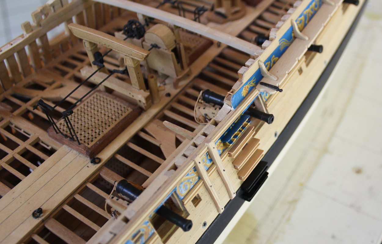
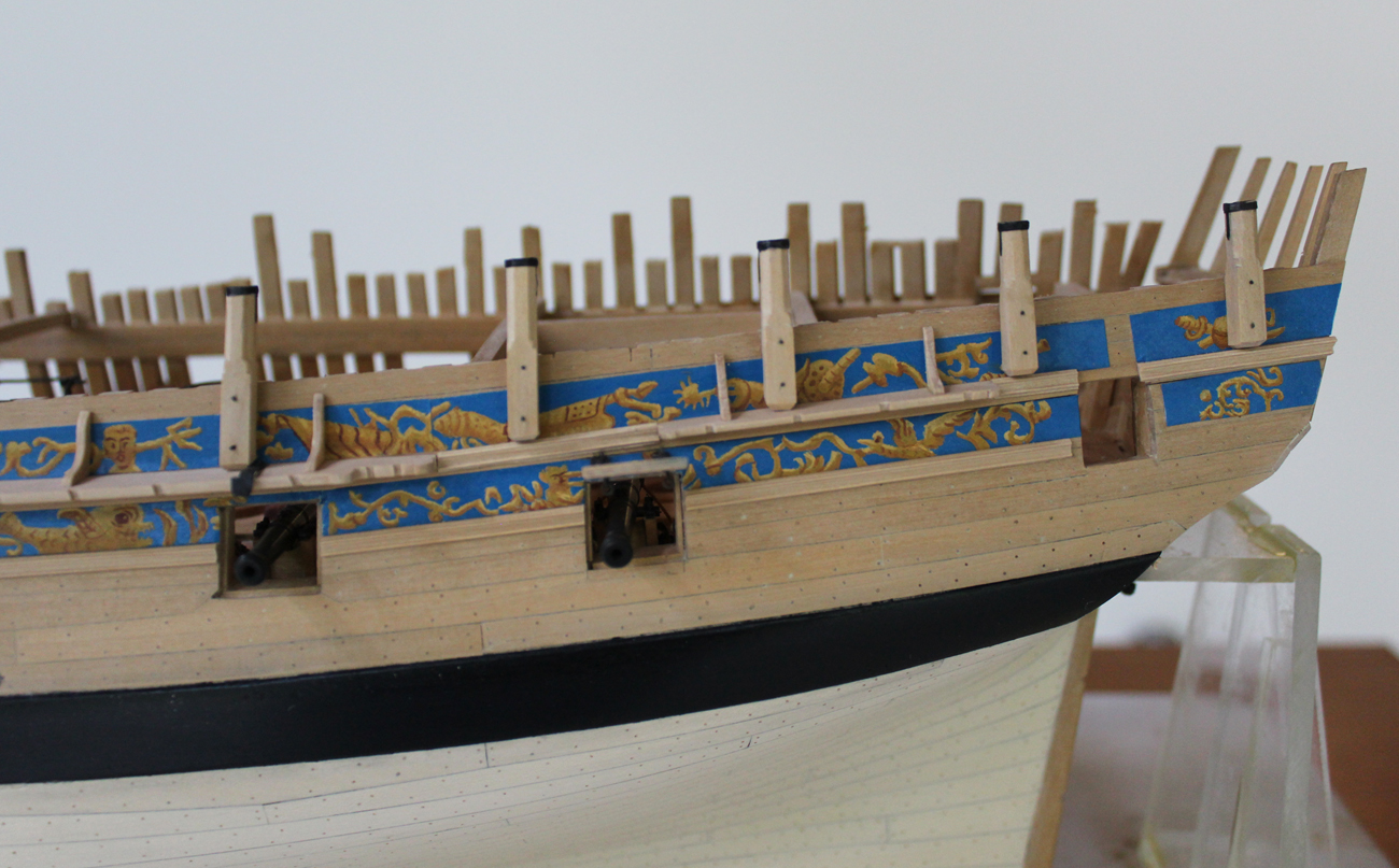
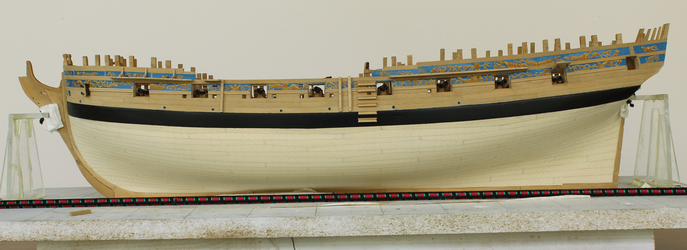
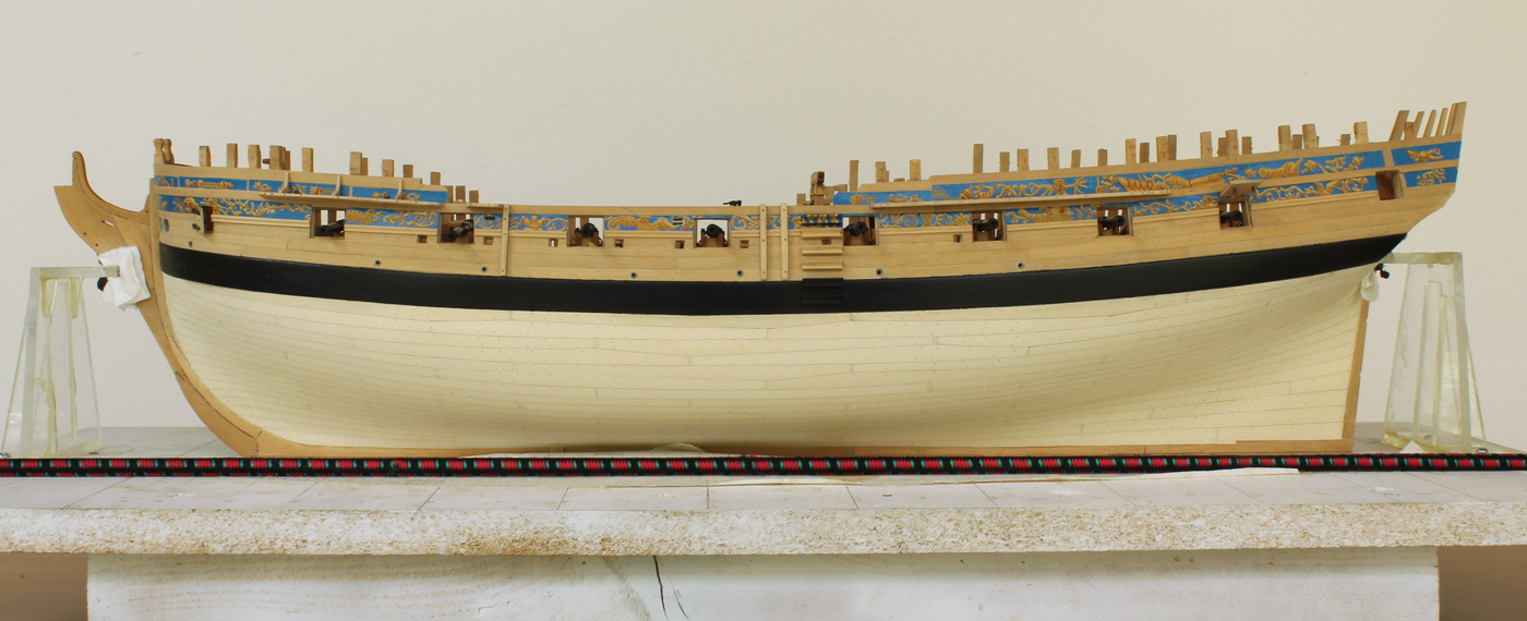
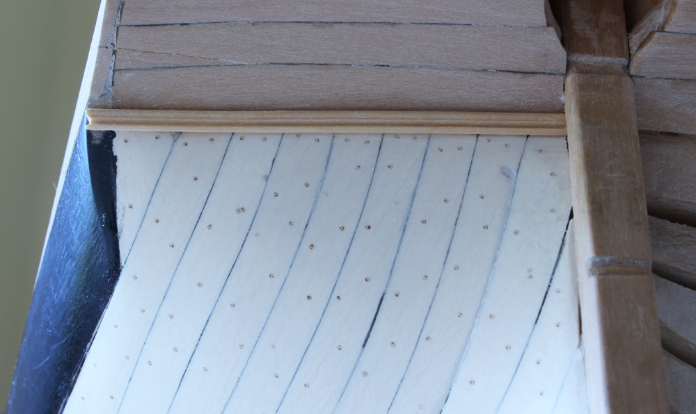
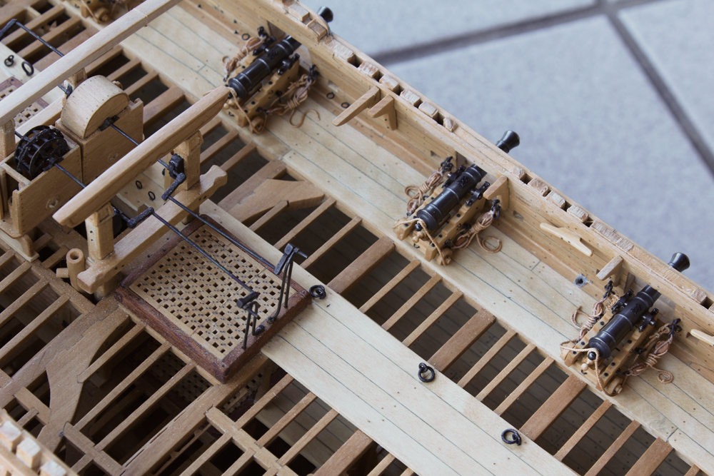
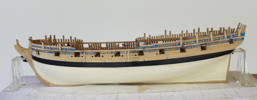
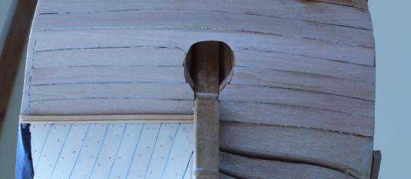
Not too much has gotten accomplished on Atalanta these last few weeks. Two weeks ago she took a trip to the Midwest Model Ship Show in Manitowoc Wisconsin. Bill Maxwell's magnificent Fly and Atalanta were displayed next to each other as works in progress. Last week was spent in the garden. This week it rained so much I was able to put in a little quality modeling time. Next week all the weeds will have grown like...weeds! The standards and most of the eyebolts have been added to the main and mizzen channels. The iron supports for the main studding sail boom are fixed to the main channel. These are a gooseneck and an eyestrap. My apologies for lack of photos-in-progress but the camera was not available until after completion. These are straightforward pieces to fabricate. The straps taper in thickness outboard to in. The "neck" on the gooseneck is a piece of brass tubing cut in half and silver soldered to the strap. There is a step on the eyestrap which was made by soldering an extra piece of brass to the undersurface and filing down the top to form the step. They are bolted to the channel. There are eight swivel gun mounts, three on the forecastle and five on the quarterdeck. Although identical in configuration, each one is different in length. I started with a 9" square stock and milled the top part into an octagon. Then, based on the plan, the final length of the octagonal section was determined and cut by hand. There is a shoulder transitioning between the square and octagonal sections and this was made with a file. The square section tapers at the foot except where it abuts the hull. It is installed perpendicular to the waterline and secured with two bolts. There is a reinforcing strap and socket which accepts the mount for the swivel gun. In real life, this is recessed into the gun mount. In 1:48 life, this was made of acid free paper which was dyed with a archival black pen. I attempted to make a decent appearing hoop but decided the only way to get an octagonal hoop was to also use paper, wrapped three times around the gun mount to get the correct thickness (0.5"). I have also finally cut off the top timbers flush with the rail. I left them long to protect the top of the ship. Now, on the port side, the gun mounts will perform the same duty. They have temporarily been kept long on the starboard side.

-
Source for belts for Dentist Drill
tlevine replied to thibaultron's topic in Modeling tools and Workshop Equipment
I have gotten mine on EBay. Here is a current link. http://www.ebay.com/itm/Keystone-Plastic-Engine-Belt-8-9-Single-belt-for-Dental-Jewerly-Handpieces-/311610258678?hash=item488d6b34f6:g:694AAOSw1KxXM0QJ -
And now it is the Gold Award winning longboat. Congratulations, Dan.
- 175 replies
-
- 2
-

-
- 18th century longboat
- model shipways
- (and 1 more)
-
Thank you gentlemen for your kind comments and thanks to everyone for the likes. Hopefully I will get to spend a little more time in the workshop soon.
-
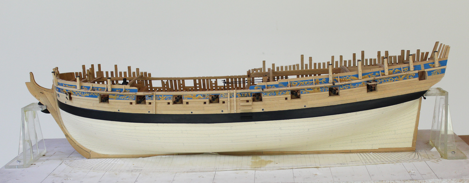
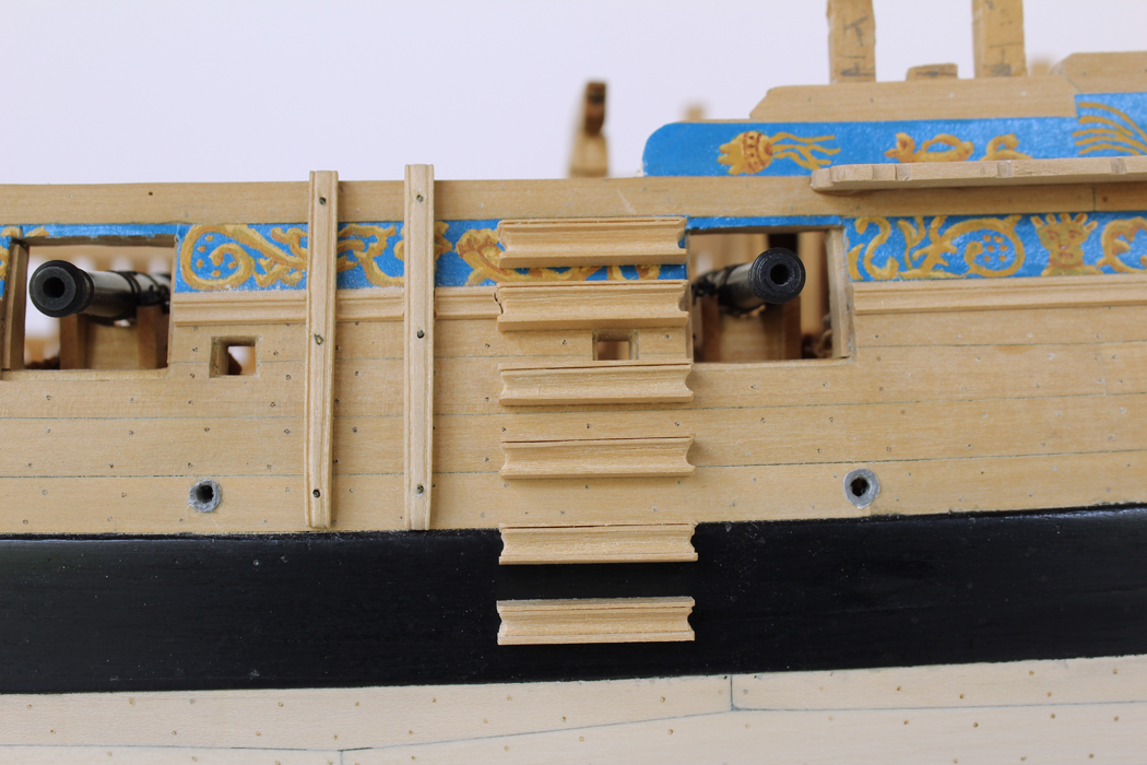
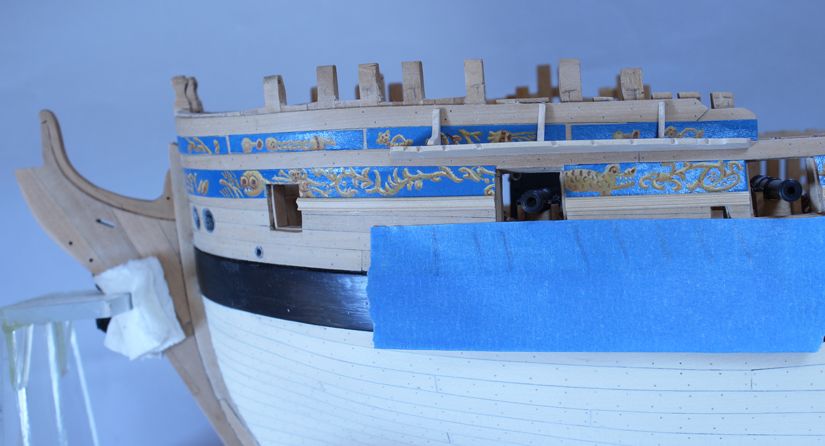
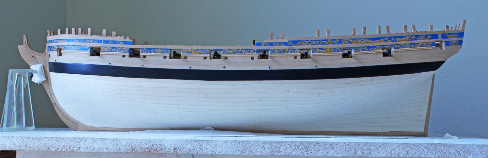
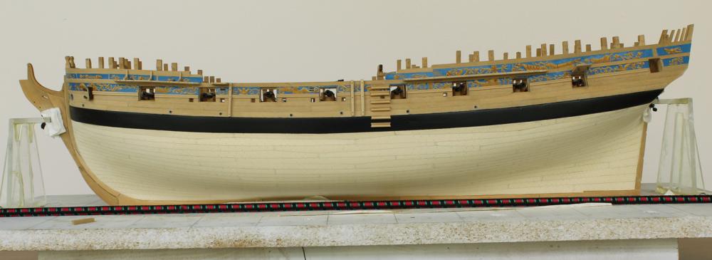
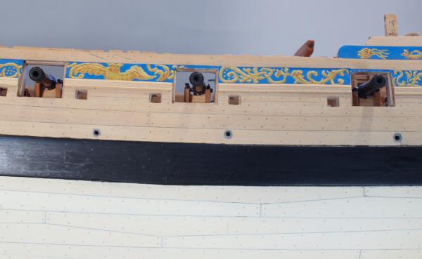
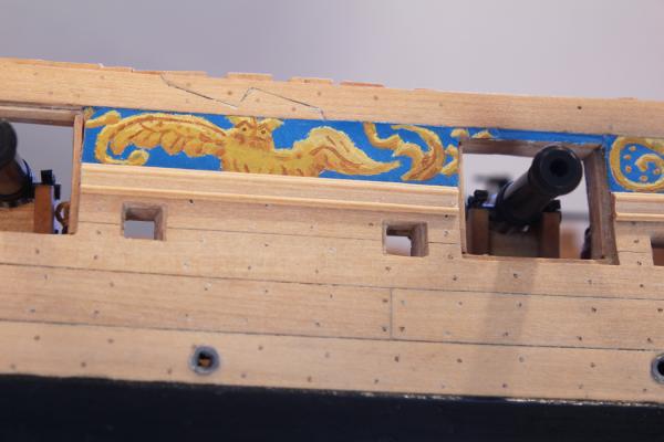
I can't believe it has been over a month since I posted to the buildlog. Unfortunately, I have not had much time to work on Atalanta. The chesstree and the fenders are relatively simple structures, being essentially a straight piece of wood with a taper towards the water. Make this taper first on an overly thick piece of wood and then sand the inside of the piece to match the curvature of the hull. There is a groove scored on the outboard side. Since the width of the piece decreases inferiorly, each groove must be cut in separately rather than together with a scraper. I used a single tooth scraper to make the groove and then turned the piece around to cut the other side. The chesstree had a sheave built into it. I simulated the sheave by drilling holes at the top and bottom of the sheave opening and then used a chisel to carve the sheave. The next step (no pun intended) was to make the six steps. These were made up by scraping a molding for the mid-portion and then laminating three strips of wood, two on top and one on the bottom to the molding. The sides of the steps were shaped with needle files and an 11 blade. The steps fixed to the wale were painted black. The frieze was carried over the outer surface of the top step. I left the top of the step solid blue. The main and mizzen channels were added next. These are pinned and epoxied to the hull since, in my past experience, they are easily knocked off. The ironwork for the channels is next.


-
Thanks, Chuck, for the photo offer. I did not realize you were the lucky owner. Was the plan you show a digital download? All of mine are simply black and white.
-
Stunning. The contrasting colors of the standards bring it all together.
- 641 replies
-
- 5
-
-
- greenwich hospital
- barge
- (and 1 more)
-
Absolutely gorgeous. Do you have any more photos of her you could share? They would come in very handy for if I decide to tackle Atalanta's figurehead. Or else I could simply commission David
-
Druxey, your work is an inspiration to us all. Mounting the sweeps on the baseboard is a reasonable solution. But it would also be interesting to have a few sweeps mounted to add "action" to the model.
- 641 replies
-
- 5
-
-
- greenwich hospital
- barge
- (and 1 more)
-
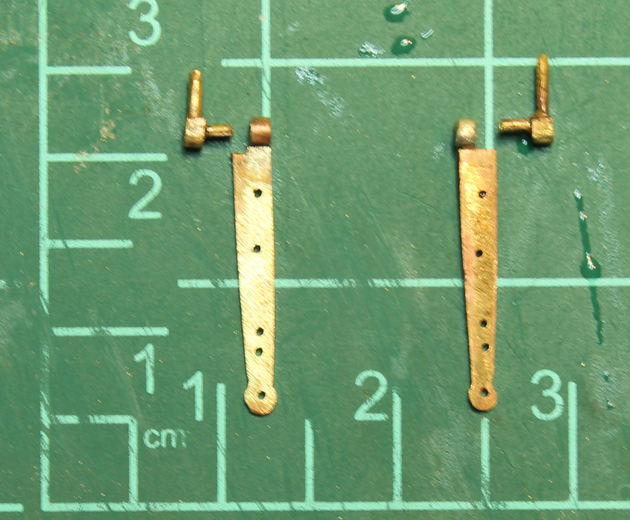
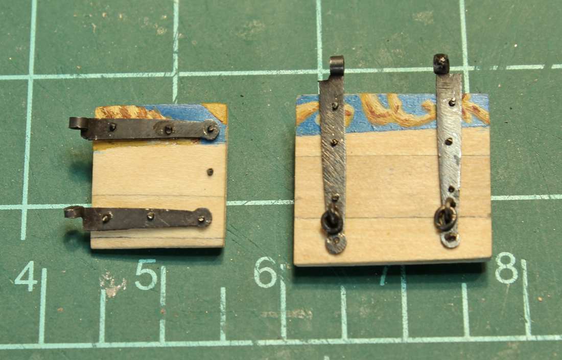
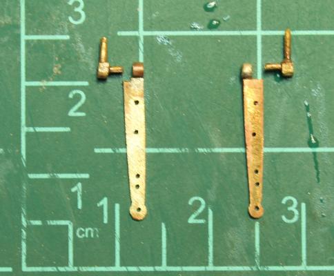
Robin, Druxey David, Greg and Grant thank you for your kind comments. Looking at the pictures I am somewhat unhappy with the file marks on the hinges. However, in reality, the marks are almost not visible. And to redo them is not in the cards!
-
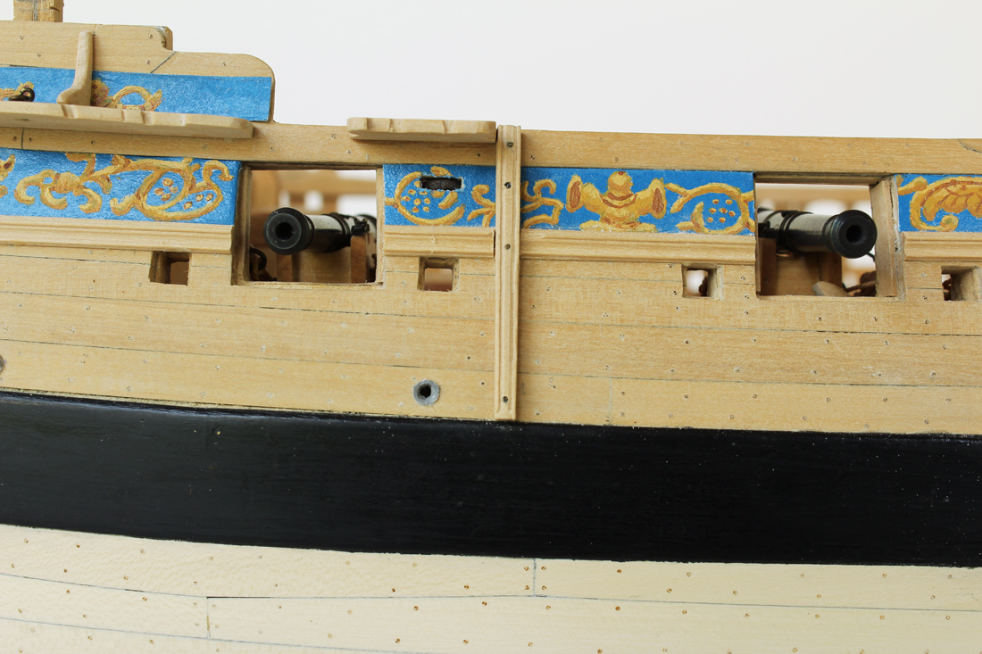
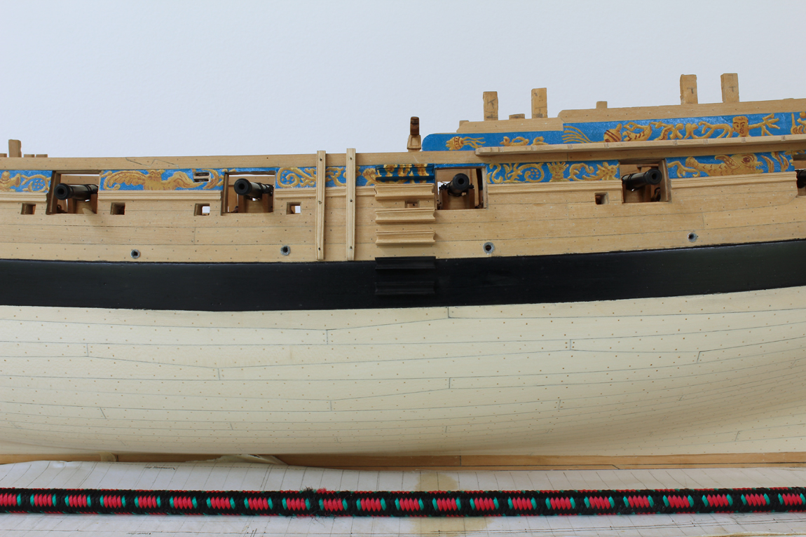
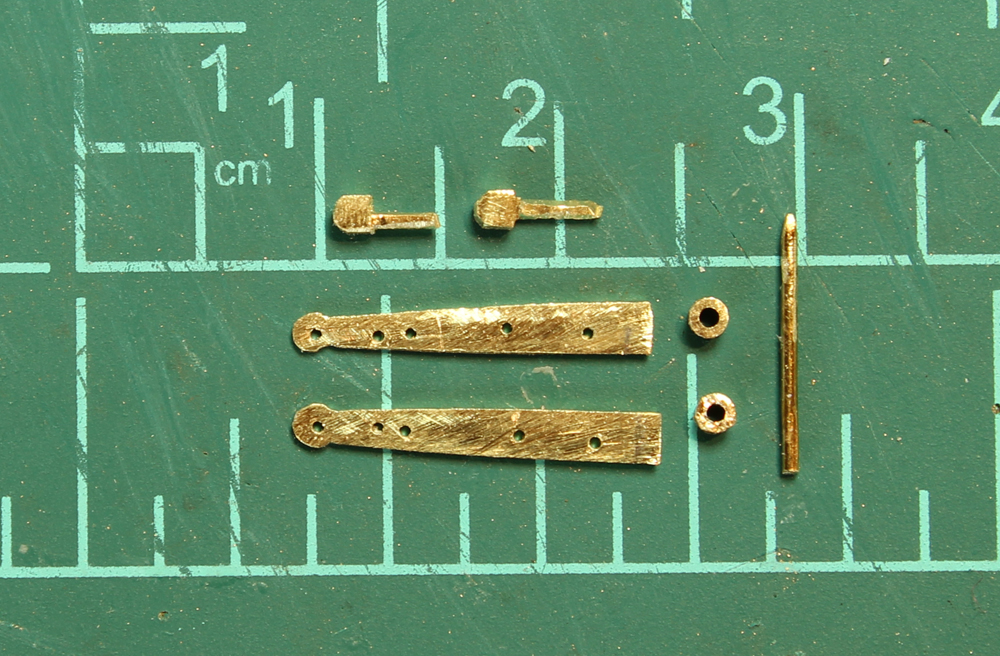
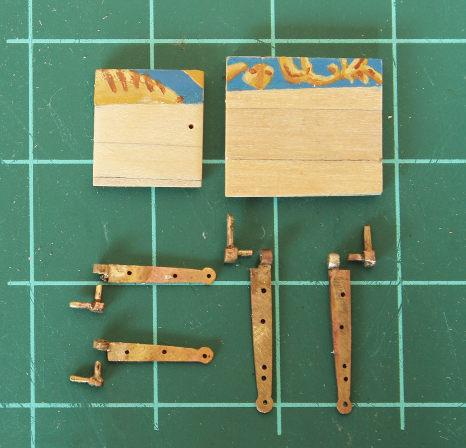
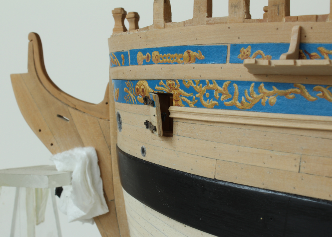
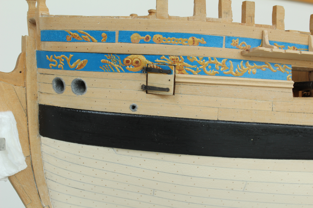
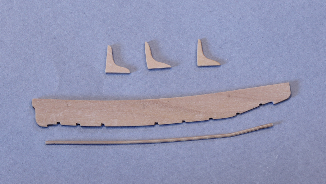
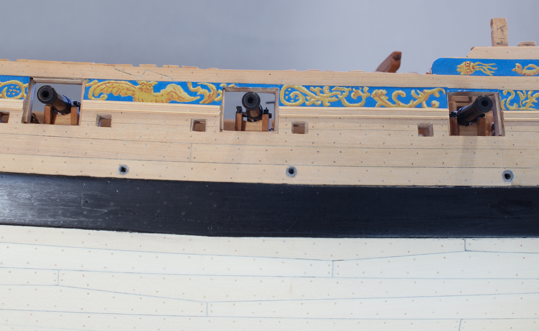
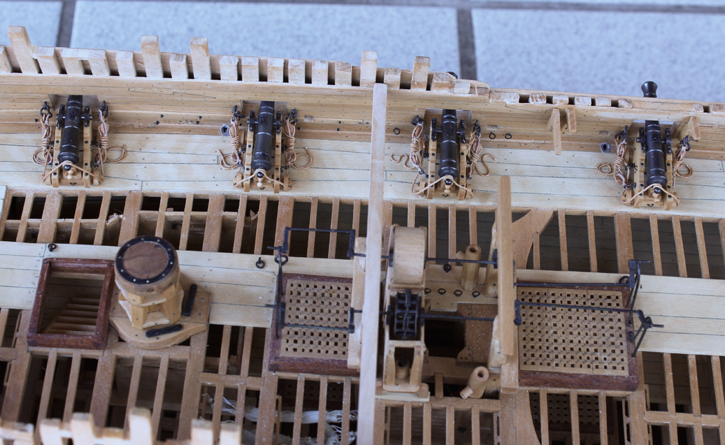
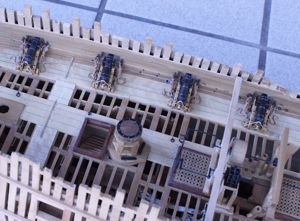
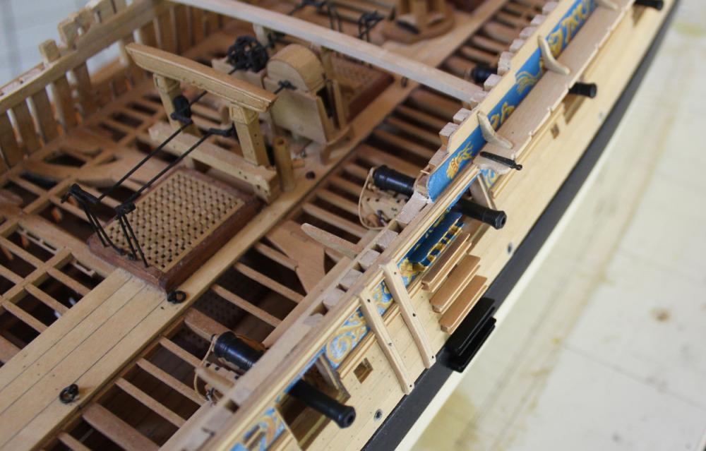
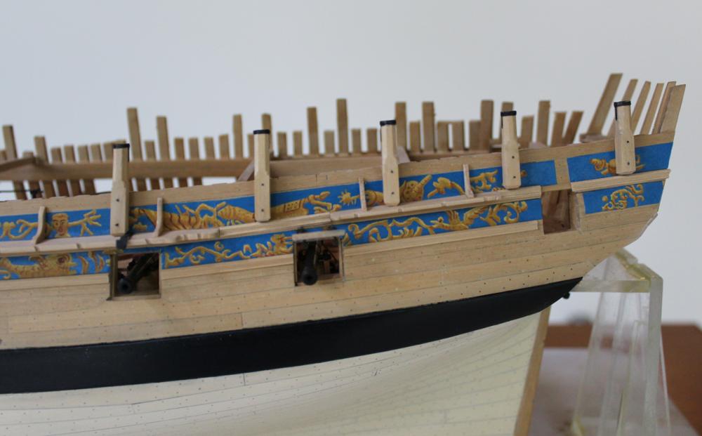
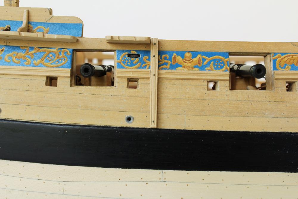
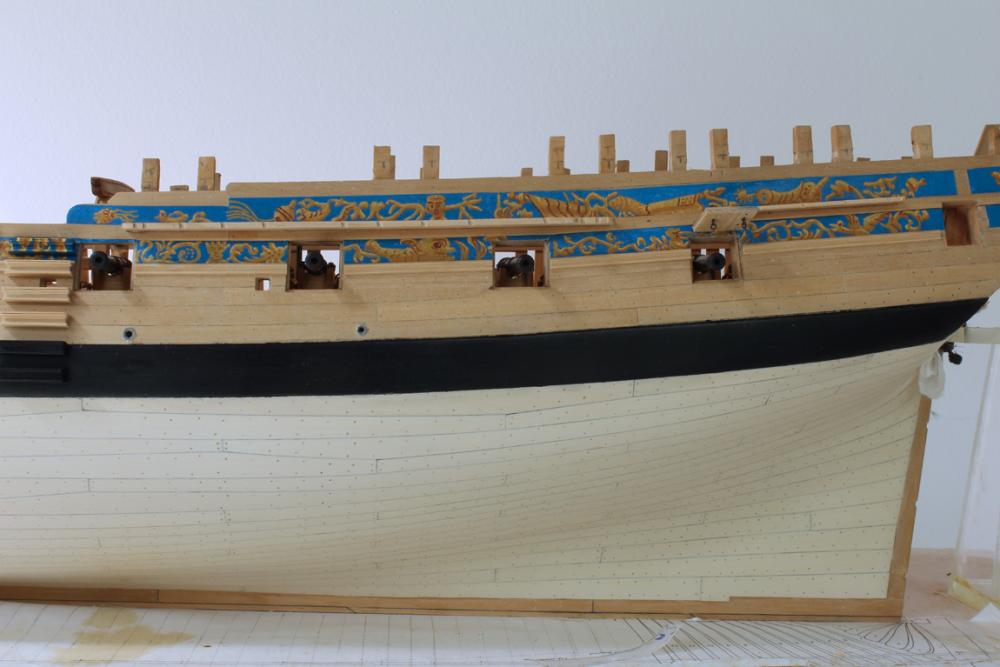
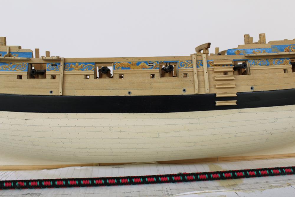
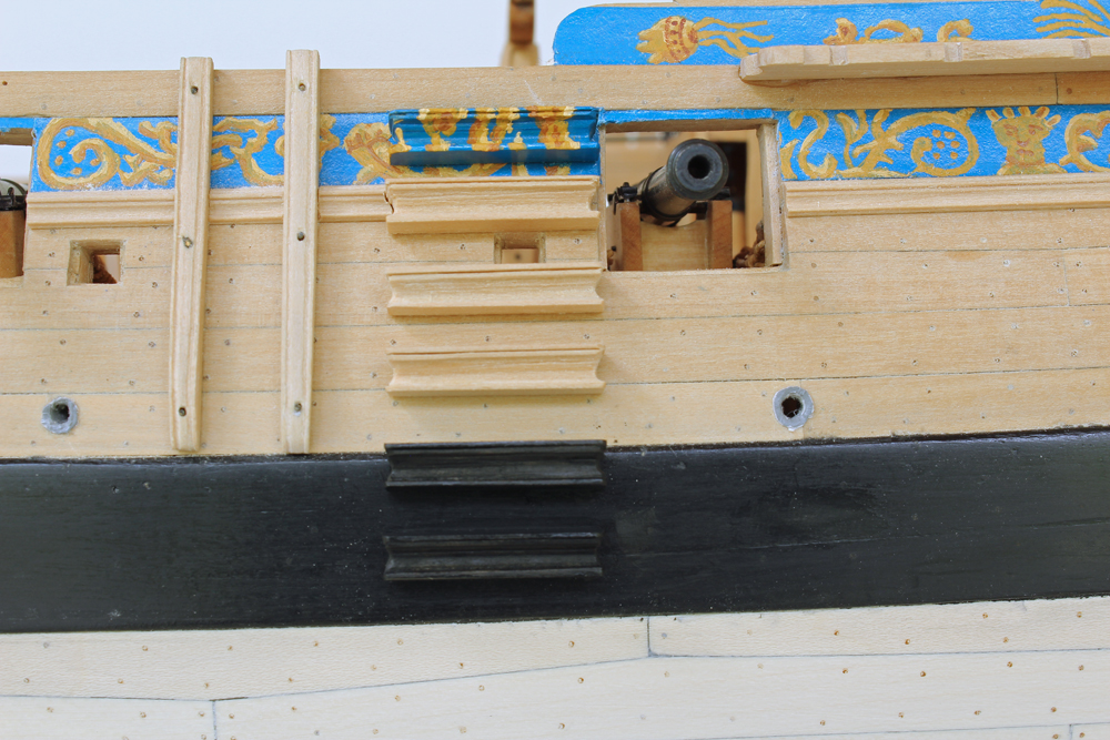
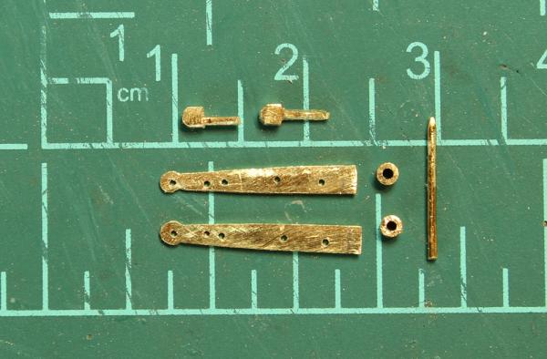
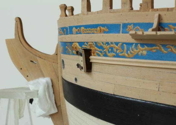
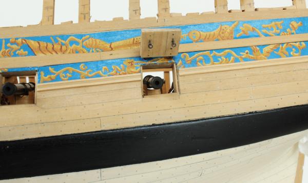
There are only two port covers. The aft one is for the last cannon. The covers are made of two layers of wood; the interior is vertical and the exterior matches the run of planking. The frieze was painted before the hinge straps were added. The hinges were made of the pieces seen in the photograph and then silver soldered. There are eyebolts on the inner and outer faces of the gun port and three additional bolts. The rigging will be added after the exterior hull is a little more complete to prevent damage. The fore port cover is smaller and allows airflow to the fore part of the ship. It is hinged on its fore side to prevent it from being blown open. There is an eyebolt on the inside face. It appears to be hanging lopsided. This is an optical illusion caused by the curved shape of the hull.


-
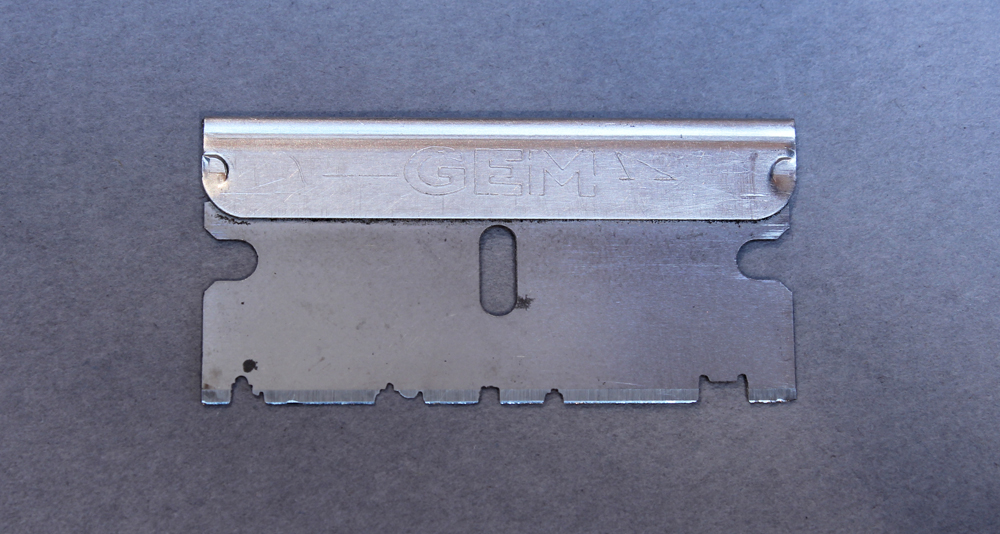
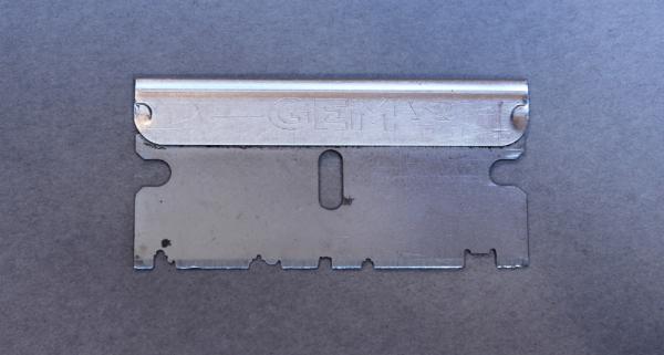
Thank you Druxey and Elijah. Nils, the key is to get the super thin cutting discs. I have also made these with Exacto chisel blades. Those are sturdier but for the few feet of molding required in this build, I consider it overkill. The razor blades are much easier to cut fine detail into.
-
Absolutely wonderful. I prefer the new color scheme as well. Are you planning on leaving the gold bright or are you going to tone it down?
- 641 replies
-
- 2
-
-
- greenwich hospital
- barge
- (and 1 more)
-
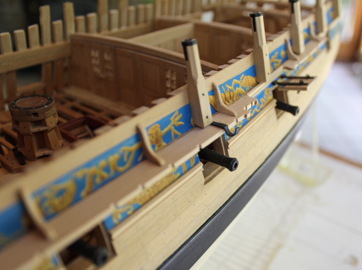
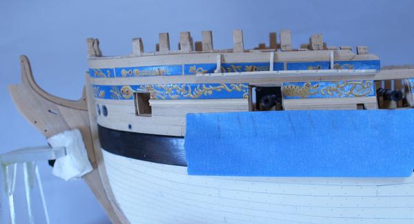
Mark, Christian and Albert thank you for you comments. Kurt, I agree. I wish it was a little more portable. Mine is wall-mounted. When I was in training, these are the exact type of drill that we used to learn how to perform ear surgery. A little more work got accomplished today. The fore channel has been cut out and thinned towards the outer edge. A rebate is cut into it for a strip of molding. On the razor blade the profile is the second one from the right. I wet the molding to navigate the bend in the channel and clamped it until dry. The chain plates are drawn in on the masking tape. This allowed correct placement and angle of the notches in the channel. Three knees prevent upward pull of the channel. In the picture it looks like the channel is angled upwards. It actually is parallel to the waterline.
-
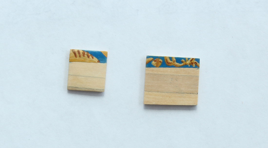
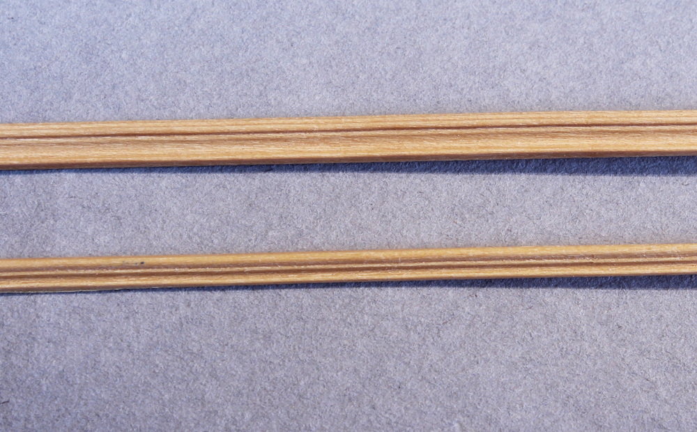
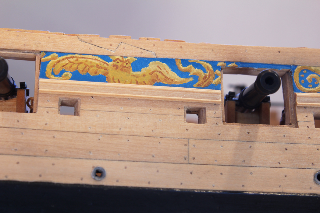
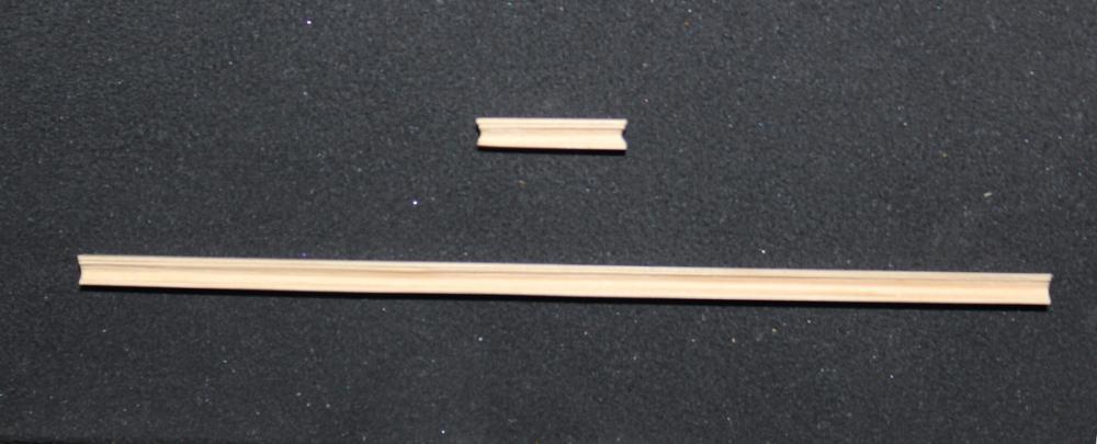
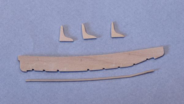
It is time to make some of the decorative rails. Suggested patterns for the rail profiles are given in TFFM. I use thin dental cutting discs which are 0.009" in thickness. They are inexpensive and readily available on EBay. Of course, they are brittle so eye protection is a must. I am lucky to have an old Emesco dental engine which gives me slow variable speed without any play in the handpiece. I cut the profiles into the sharp end of a regular single edge razor blade. On this razor blade I have four different profiles and one oops. I have also used Exacto blades for this. Stock which is slightly oversized is used for the moldings. This prevents the cutter from moving too much side-to-side during the scraping process. The tuck molding is located at the junction of the hull planking and the lower counter. This molding has an undercut on its back surface to compensate for the curve of the hull. The profile was carried over to the outer edge of the molding. The discoloration in the wood of the counter is bleed through from applying finish internally and (hopefully) will not be seen when the exterior finish is applied. The waist rail is located just below the frieze. I will add the extreme fore and aft pieces after the rails and quarter badge have been installed.


-
Greg, the fore-aft width of the frame is 0.19" and the top of frame thickness is 0.13" at midship. I hope that answers your question.
-
Thanks Albert, Mark and David. And thanks for the likes. Greg, what do you mean by the ribs?
-
Thanks Tom. This kind of repetition is why I hate rigging. Greg, at one point there was even a lazy seaman in one of the hammocks. But robin opened my eyes to how cheesy it looked and I sent him packing.
-
If you found something "tricky" the rest of us mere mortals would have found it impossible.
- 641 replies
-
- 6
-
-
- greenwich hospital
- barge
- (and 1 more)
-
Jose, Tom, Elijah, Greg and Mark thank you for your comments. Druxey, if I had to rig one more cannon I think I would have gone postal. Truthfully, if this were a larger ship I would probably have done only one or two cannon with all the trimmings.
-
Looks very nice. I am glad my concerns were unfounded.
- 64 replies
-
- 4
-
-
- 18th century longboat
- model shipways
- (and 1 more)
-
Your work is always beautiful. Watching it develop, step by step, simply enhances the appreciation of your skills.
- 641 replies
-
- 4
-
-
- greenwich hospital
- barge
- (and 1 more)