tlevine
-
Posts
2,033 -
Joined
-
Last visited
Content Type
Profiles
Forums
Gallery
Events
Everything posted by tlevine
-
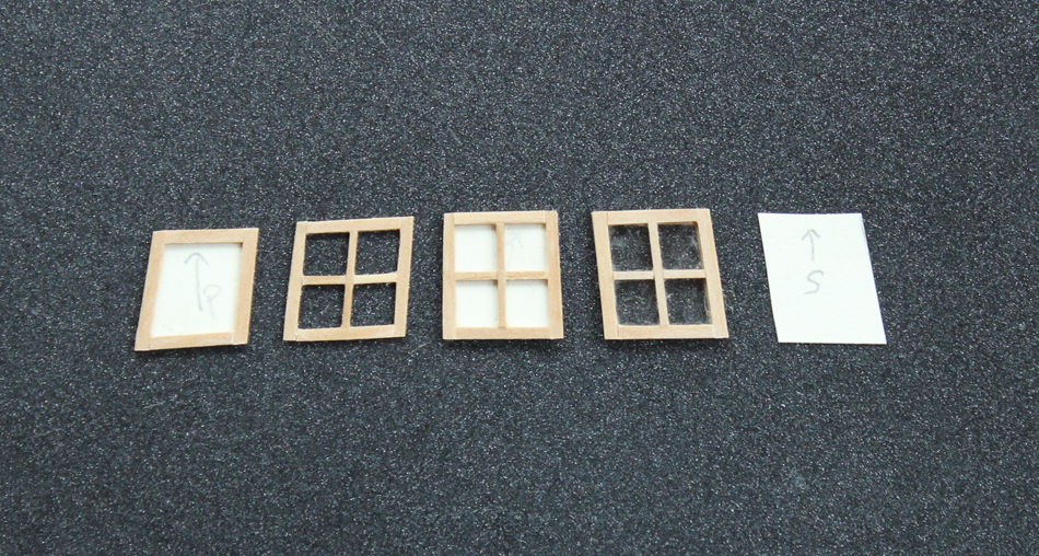
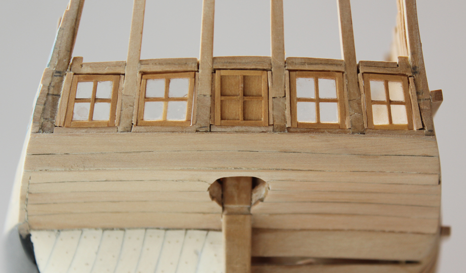
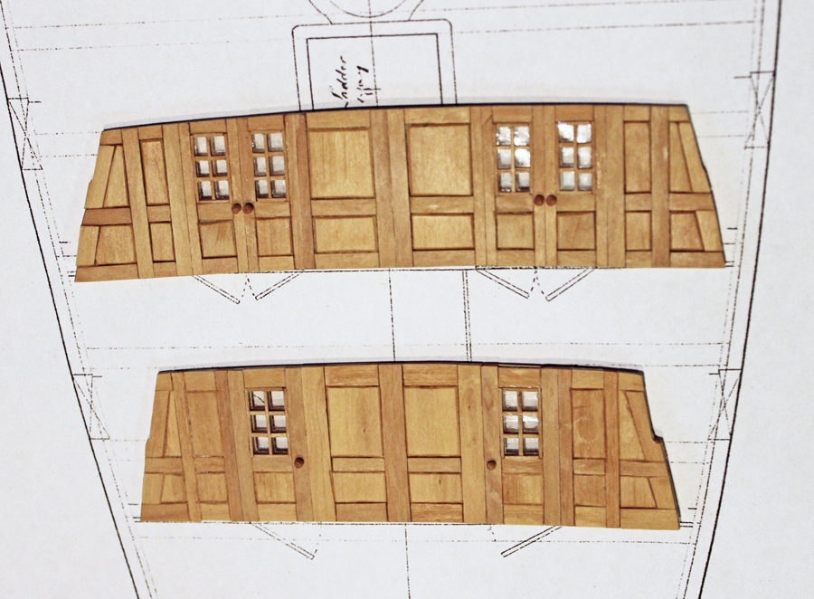
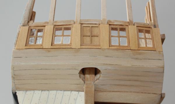
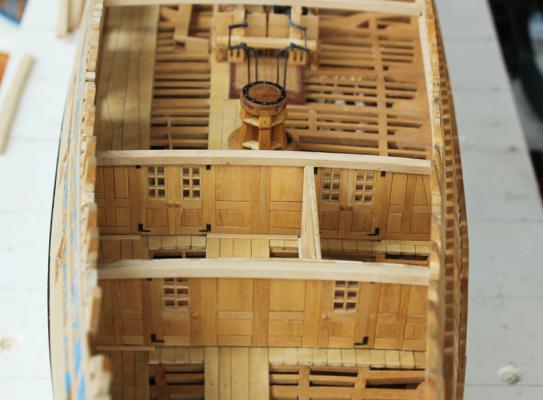
 The next items to make are the windows themselves. Since these are not structural I made them simply by edge gluing rather than finger jointing the stiles and rails. Also, the mullions are not half-lapped but are simply edge glued as well. The glass is mica. I was very surprised how well the glue adheres to the mica. The first picture shows the sequence of construction. First a template is made of the window opening. The stiles and rails are glued to the template. The mullions are then added. The template is peeled off the framework and mica is put in place. Finally, the inner frame and mullions are added. The center opening was not glazed as it looks directly into the back of the rudder trunk. The windows are glued in place. The small gaps will be hidden under the munions and decorative moldings. The discoloration of the wood of the upper and lower counter is from internal finish seeping out between the planks. This will not be a problem after the external structure has a coat of finish. The munions are trim boards between the windows which hide all of the internal structural components. External to this, the plans show a column with acanthus leaves. I cannot tell from the plans whether the leaves are carved or painted. This will be added when the rest of the stern is completed. One of the central munions is not the same shape as the other five. After careful consideration and a few choice words I determined that the only way to correct the problem would be to rebuild the entire stern. And that wasn't going to happen! It looks worse in the photo than in real life. Once the decorative trims and columns are added I do not think it will be very visible (except to me). These windows open inwards. There is a quarter round sill which acts as a stop to prevent the window from opening outward.
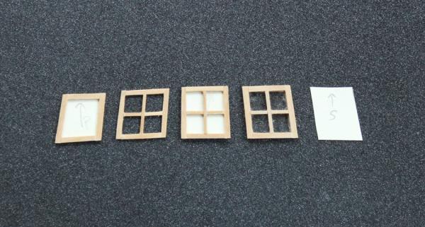

-
Druxey, Nils, albert and Remco thank you for your comments. And thank you to everyone for the likes. The next thing to tackle will be the windows themselves.
-
Seeing your build brings back a lot of memories, both good and bad. Peregrine was my first wooden ship model, completed in 1983. I did not have a clue what I was doing and the instructions were of no use. I even bought an Italian dictionary to help translate them. You are doing great. Keep up the good work and above everything else, enjoy yourself.
-
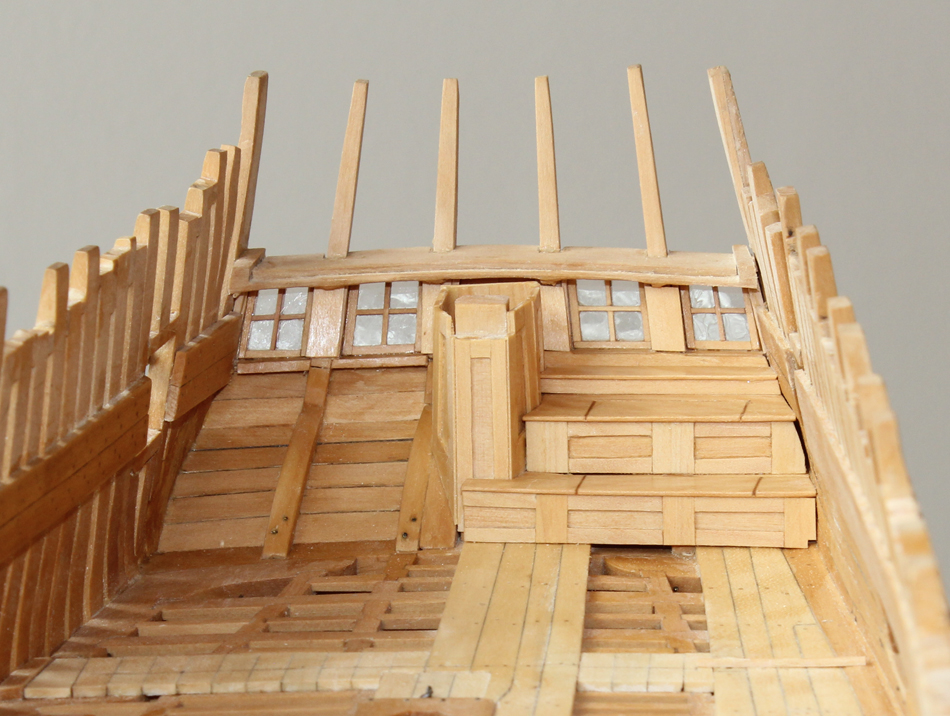
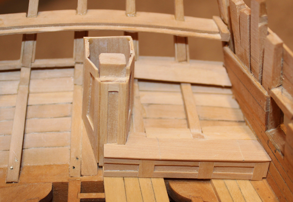
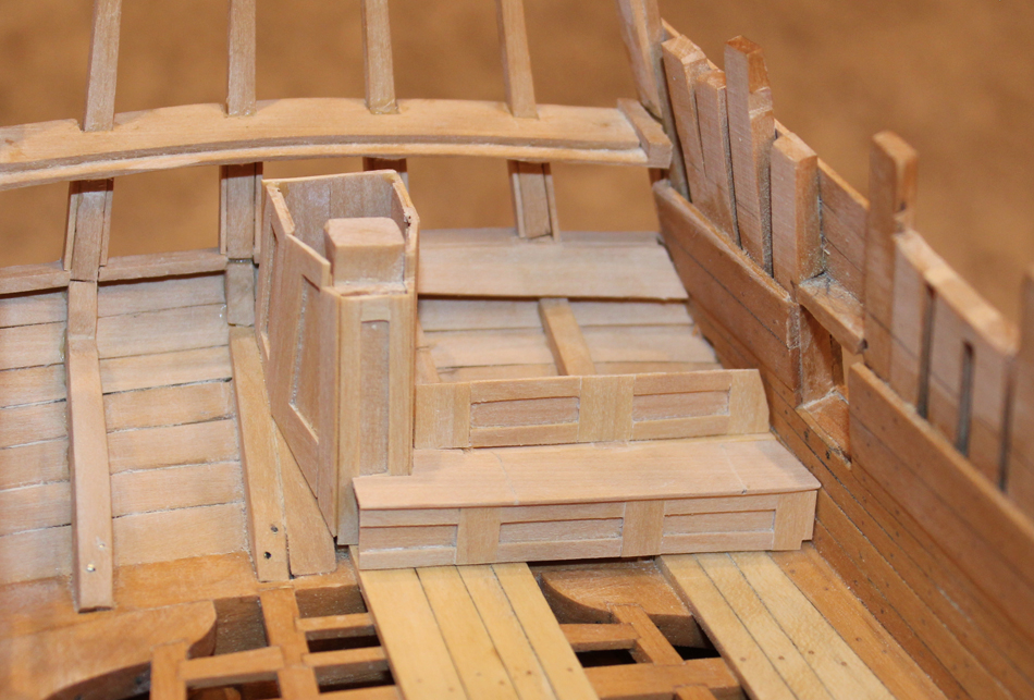
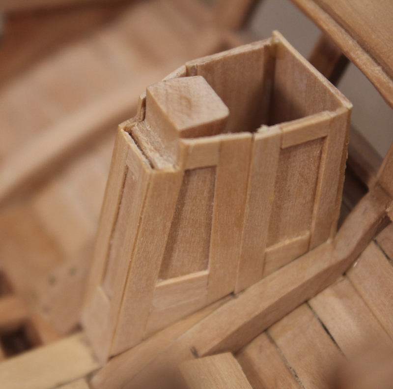
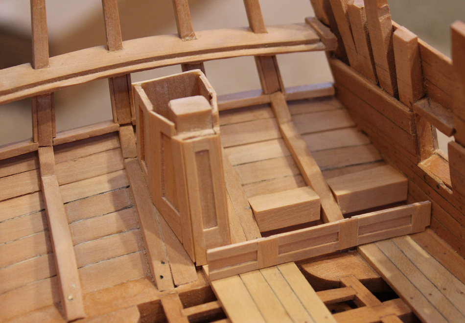
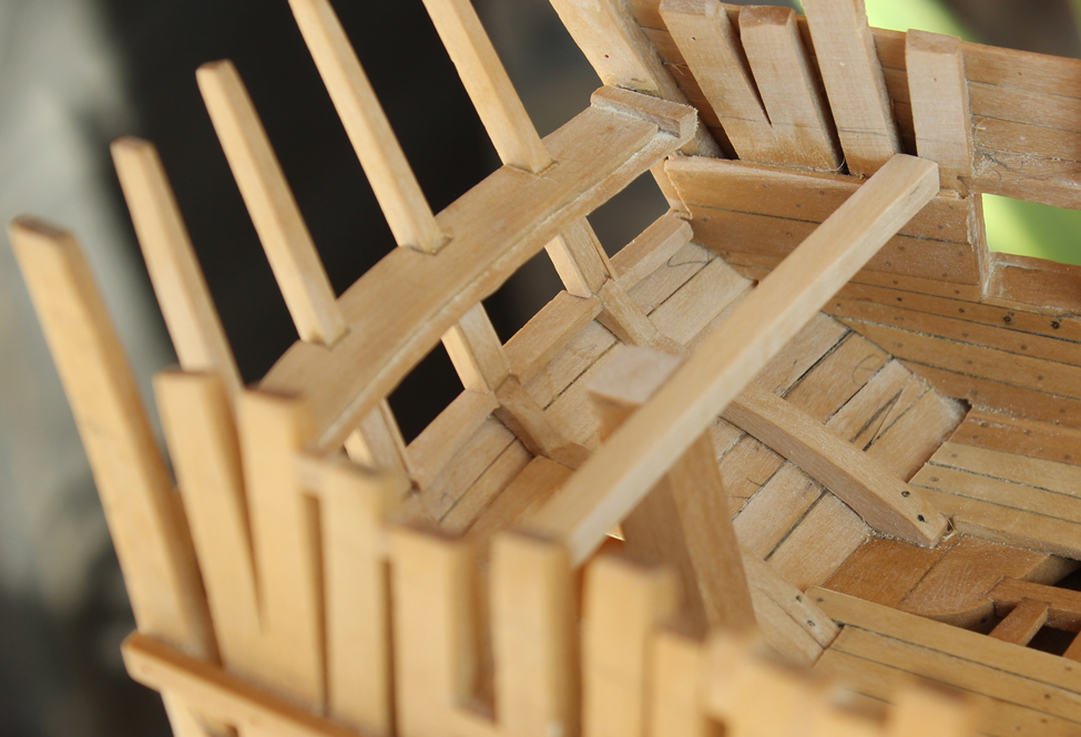
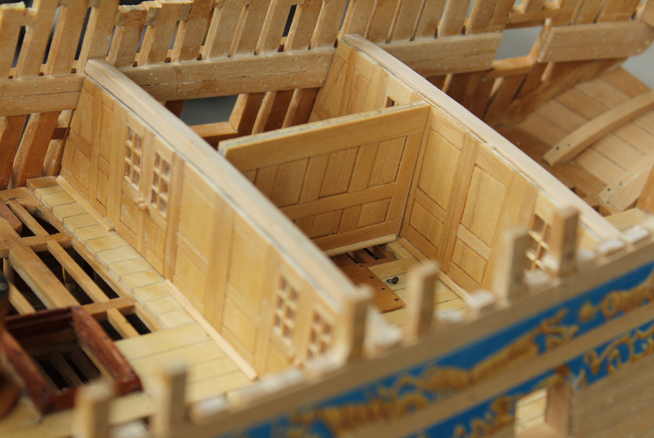
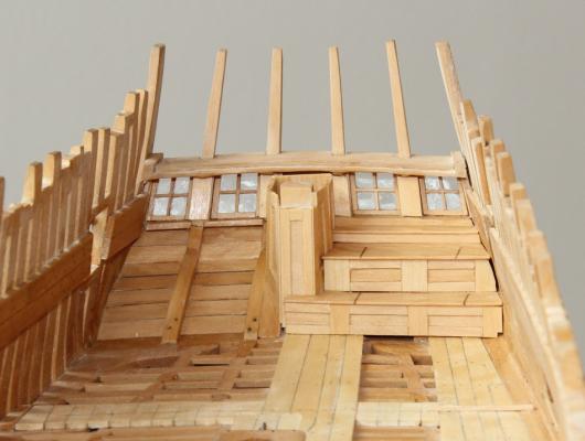
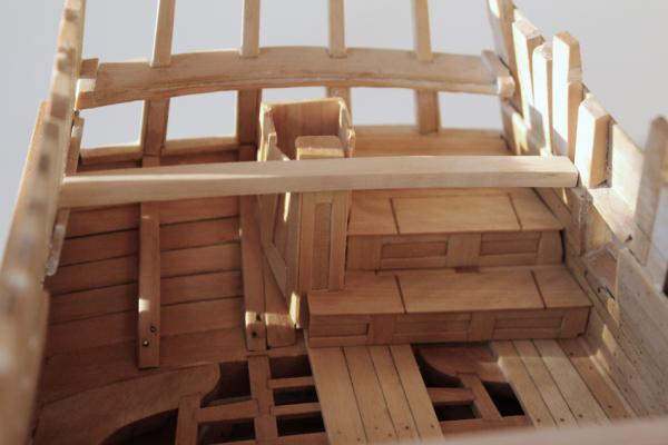
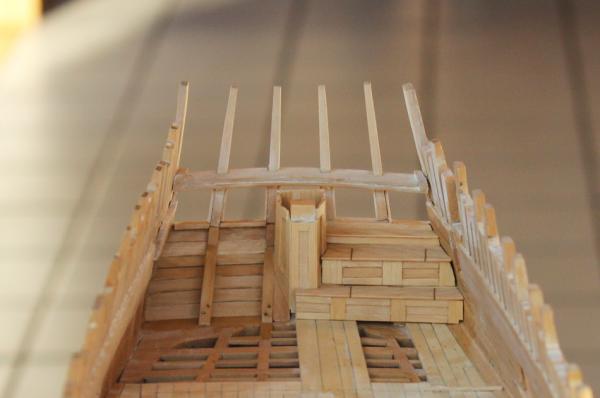
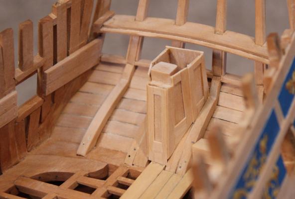
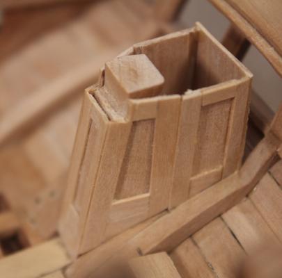
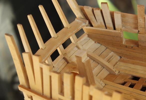
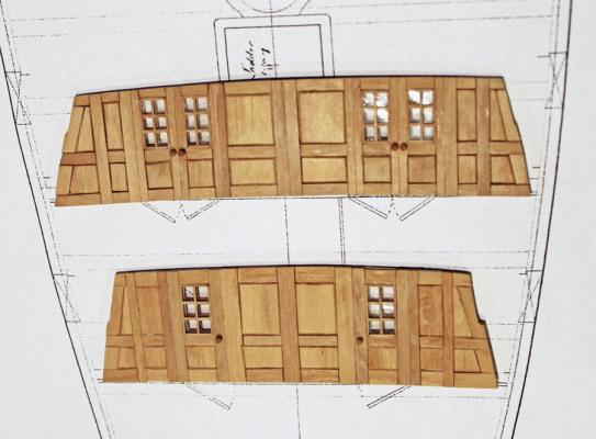
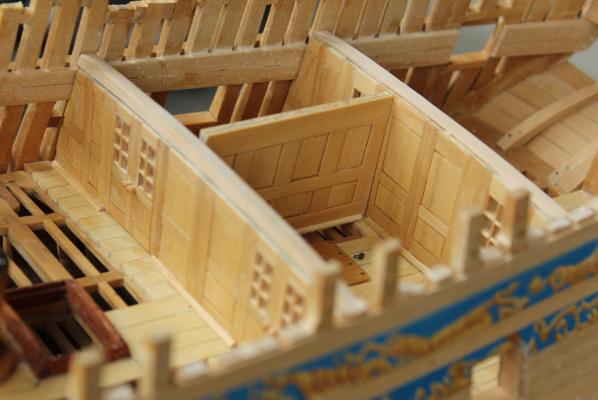
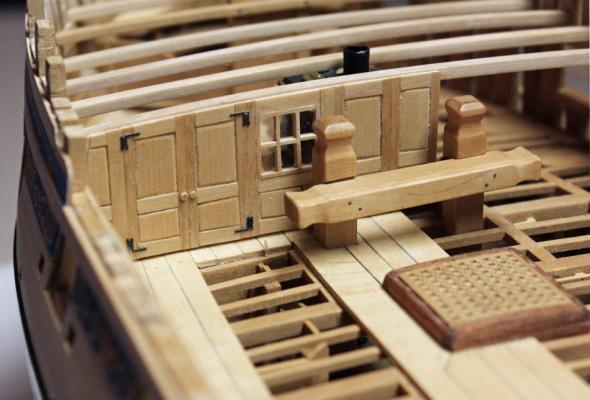
At this point, all that was necessary was to pop the side frames off the stern timbers and apply new ones that extended the full depth of the timber. An exterior stop will be applied after the window has been installed. Thanks again, Danny. The rudder trunk extends from the fore face of the stern post to just aft of the opening for the rudder. There is a gap between it and the center window. It is trapezoidal in shape. Because of the angles involved and the shape of the lower counter, templates were used to get the correct shapes for the pieces. Lockers ran the length of the aft wall of the cabin. They are deep enough to provide additional seating space. On Atalanta there are two tiers of lockers and a shelf above the upper locker below the level of the window sill. I have chosen to model only the port lockers, leaving the starboard framing open. The first step was to develop a template for the profile of the lockers and counter. This was taken off the plan. The lowest vertical element was made first. Paper templates were made for each piece of the assembly. I glued the vertical stiles onto the template and then installed the horizontal slats. After it was dry, I peeled off the paper and glued in the recessed panel. A cleat was installed on the blind side to stiffen it and give a wider gluing surface. Finally, it was glued in place. The horizontal element needs to be supported at the stern timbers. I inserted wedges between the timbers to provide a gluing surface. In the pictures it appears that they are not at the same height or angle. This is an optical illusion which is occurring because the deck curves but the locker is horizontal. I had a choice at this point to either make a functional locker door and frame or simply make one piece and draw the door in with an #11 blade. I chose the latter. This actually makes the outline of the door stand out better than if I had made it in two pieces. Be sure to carry the incision around the fore edge of the door. It barely shows until the finish is applied. I toyed with the idea of having one of the lockers open and filled with rolls of maps but decided against. None of the other rooms have elements that would have been brought on board (with the exception of the hammocks) so for consistency I left the lockers closed. I will not furnish the space for the same reason. The second vertical element starts approximately two inches behind the edge of the door. The panels are shorter because of the rudder trunk. I have also installed the interior upper counter plank to act as a gluing surface later. The second horizontal element is installed, followed by the third vertical element and the shelf. Because of the height, the third vertical element has no ornamentation. The last two pictures show how the outline of the door stands out after a finish is applied. I still need to install hinges. In the last picture, the angles still look "off". This again is a function of the sloping floor and the horizontal locker door, combined with the angles of the hull planking and my bad photography skills. In real life it looks correct.


-
Echo by Maury S - FINISHED - Cross-Section
tlevine replied to Maury S's topic in - Build logs for subjects built 1751 - 1800
The volute and how it blends seamlessly into the molding looks great. -
The use of wire pegs to secure the quarter gallery framing is brilliant.
-
Danny, do you know how these windows were held open? Hook and eye? Pulley? It is tempting to show the starboard (unplanked) side with the windows open but I am concerned that it would detract from the beauty of the stern.
-
Thanks everyone for the likes and comments. In particular, a huge thank you to Danny. I must admit I was wondering how one would keep the window open. Happily, I am still at the stage where I can correct the problem.
-
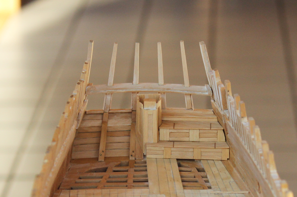
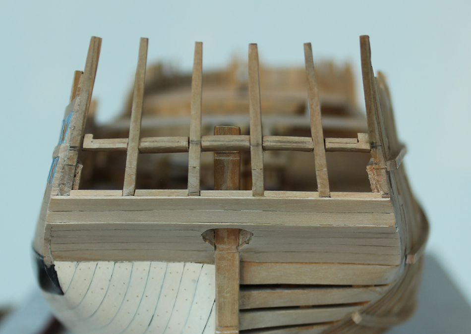
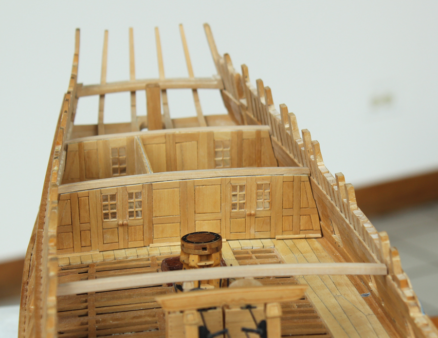
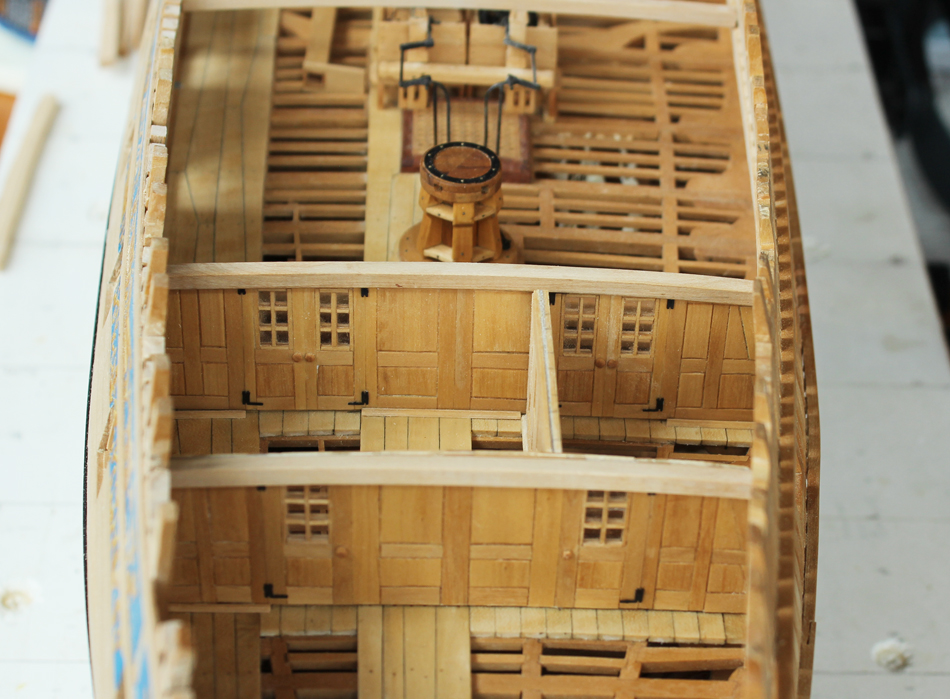
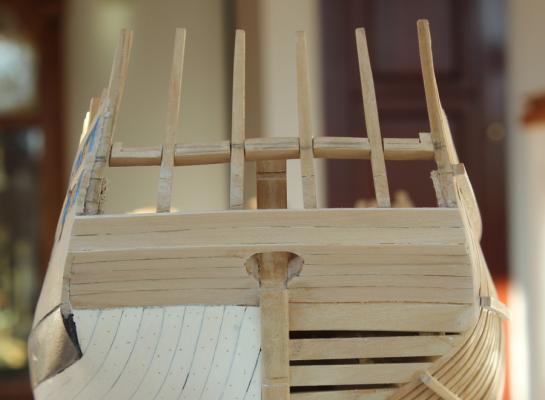
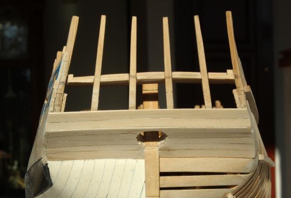
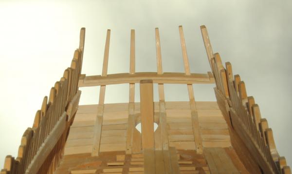
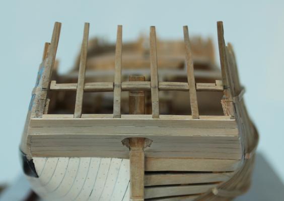
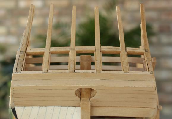
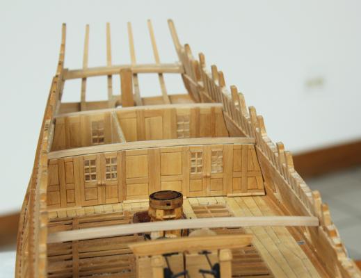
Time to spend a little time in the stern. What should have been the easy fabrication of a few planks and several window frames turned into a three day project. The upper counter is make up of two planks. Since there is side to side curvature, these were made with paper templates and then cut to shape. So far so good. Now it is time to make the frames for the stern lights. Something does not look right. I make the lower sills and install them. Something really does not look right. The windows are too short. So out come the plans and everything is remeasured. The lower counter is 2 mm too tall, which made the upper counter 2 mm too tall. The quarter deck clamps are 1.5m too low at the stern and therefore the quarter deck transom is too low. This is a perfect example of cumulative error coming back to haunt you. In this case the fix included removing and correcting the lower and upper counter planking and raising the quarter deck transom. The deck clamps are very firmly affixed so the last few beams will have shims placed at their edges to compensate. The window height was still a tiny bit too short so I thinned out the lower edge of the quarter deck transom to buy a little more height. Like any normal ship modeler, the last thing I thought about at this time was taking pictures for before/after shots. Consequently all the pictures are "after" rebuilding but before final sanding. The first three pictures show the rebuilt counters. I was playing with lighting and exposures and accidentally came up with the second picture. The stark contrast of the light wood against the dark background helps to see the increased height of the windows. And for the record, the irregularity of the lower surface of the quarter deck transom has been corrected. Once the upper counter was in place, the lower sills were installed. The sides of the frame are recessed back from the aft edge of the lower sill. This provides a stop for the out-swinging window. Since the lower counter was modified, I decided that now would be a good time to make sure the rudder sat properly behind the stern post. Happily, there was no problem. The stern post terminates at the level of the quarter deck top-of-beam. One of the beams is notched into the fore face of the stern post. In the last photo you can see how the ceiling and the quarter deck clamp has been cut back to make room for the window stops. Additionally, you can see the transom elevated approximately 1.5 mm above the deck clamp.

-
Thank you everyone for the compliments and the likes. The mica is wonderful to work with. It cuts easily with either scissors or knife. Its only drawback is that it is so soft that it scratches easily, even with a soft cloth.
-
Tool for Sanding Inside of Curved Pieces
tlevine replied to ChrisLBren's topic in Modeling tools and Workshop Equipment
If I have a lot of sanding to do (frames or deck beams) I use an oscillating spindle sander. A lower cost alternative, if you already own a drill press, would be to buy sanding mandrels and sleeves. For light-duty tasks I use a setup similar to the one Mark shows. -
Overhead storage seems right to me Alan. Thanks, Christian. Bill Maxwell generously gave me some of his sheet mica for the windows. So, of course, I had to remake the fore bulkhead window and re-glaze it with mica rather than acetate. For those of you not familiar with his work, take a look at his Fly at http://www.byrnesmodelmachines.com/projectphotos1.html?proj=74 The aft bulkheads were made in similar fashion to the forecastle ones. They are only temporarily positioned to facilitate fabrication and insertion of the quarter deck beams.
-
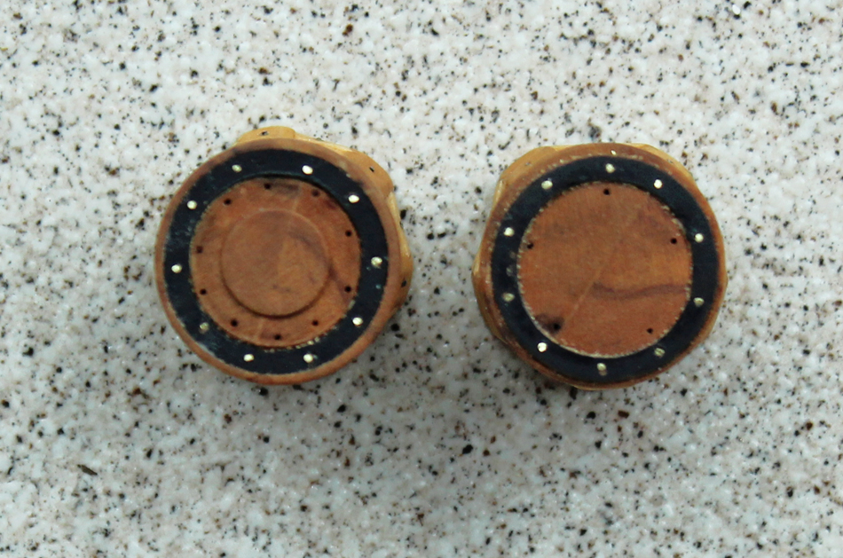
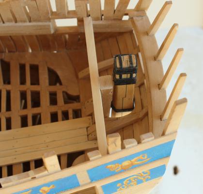
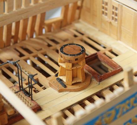
Chuck, David, Albert, thanks. I have had a little more time to work on the capstan details. Bolts are used to secure the whelps and the chocks to the spindle. Bolts are also placed through the reinforcing ring. I left these bright to contrast with the black color of the ring. They are actually countersunk bolts. I did not have any brass thick enough to machine the pawls, so these are made from wood which has been painted black. Sorry for the sawdust in the first two pictures. This is an example of the camera seeing more than the naked eye and the capstan heads have since been cleaned. Although I have drilled holes for the capstan bar retaining chains, I have decided not to model them. They look "messy" to me and detract from the appearance of the capstan head. I also figure I have a few months to finally make up my mind about them. I have also not decided whether I will insert the bars. Could anyone tell me where would these have been stored when not in use?
-
Fantastic to see you back at Speedwell. Do you know if that twisted iron is typical for the class or specific to Speedwell?
-
I agree that it looks great the way it is. I'm also amazed at how clean everything is. Not a speck of sawdust anywhere!
-
Ben, degame is another hardwood which is not seen too often. Many years ago, someone recommended it for mast making and so I bought a piece from Dave Stevens. I did not like it for masts because this piece had a tendency to warp. Grant, Dave, Greg and Martin, thanks for your comments. Greg, hopefully I will get to that ship's wheel in the next year or two! One nice thing about the rotary table is the screw for the chuck. For items that are better held in the 3 or 4-jaw chuck, rather than the vise, it holds it securely and at 90o.
-
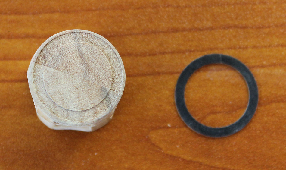
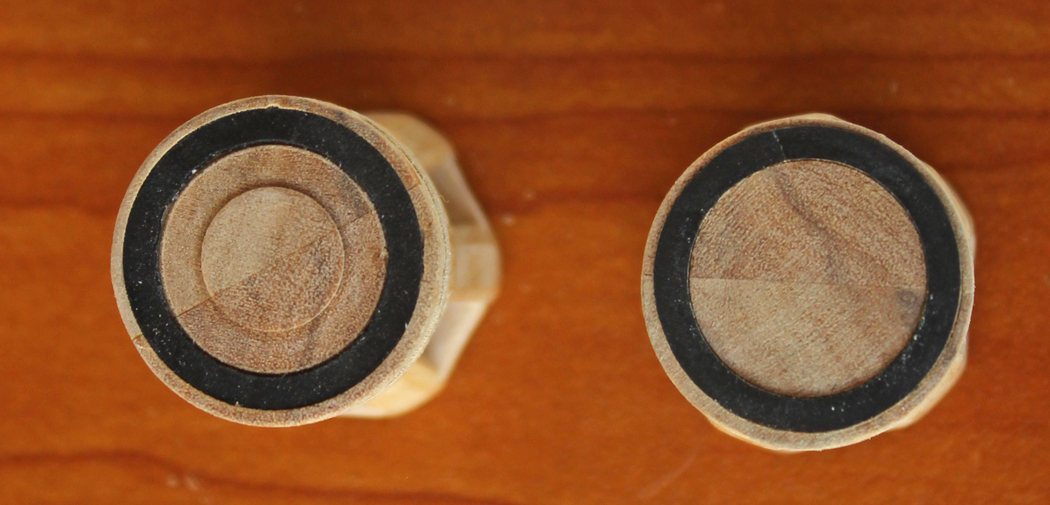
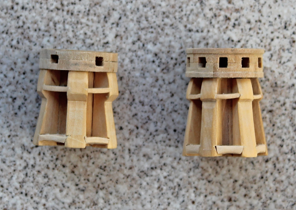
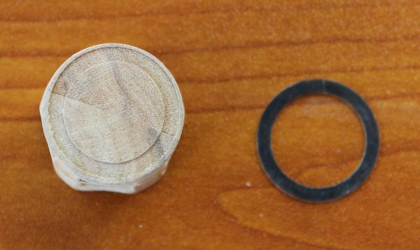
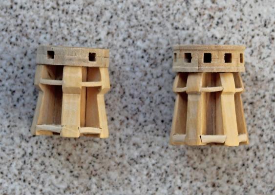
The iron reinforcing bands were made out of very thin slices taken off the blank. These were then glued back on and the correct width was milled. I used an archival marker to blacken the bands and inserted them into the drumheads.


-
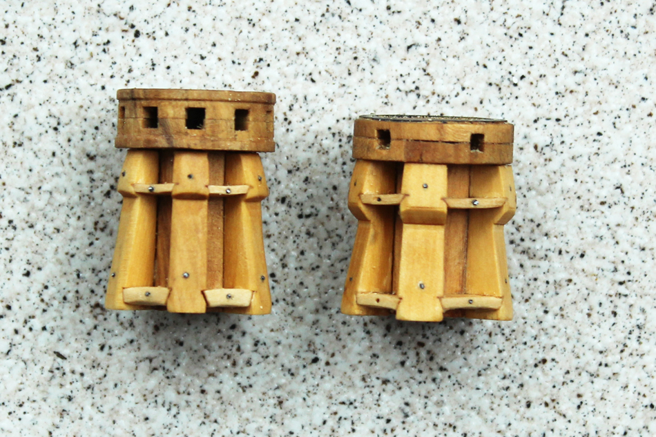
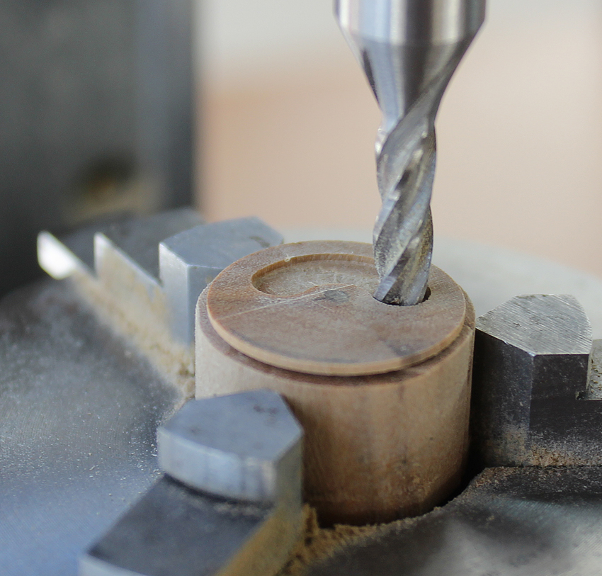
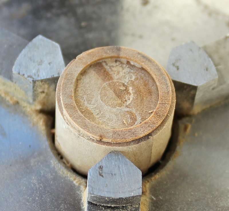
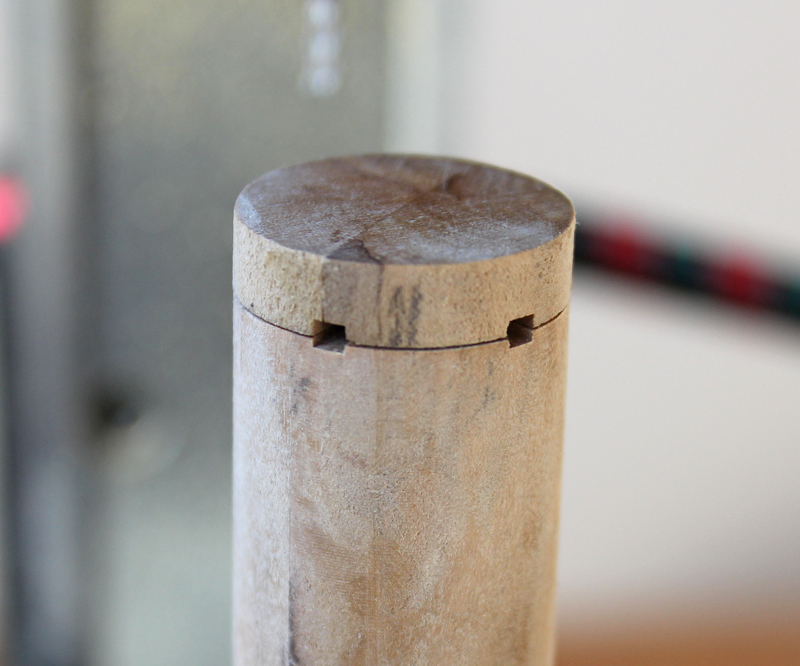
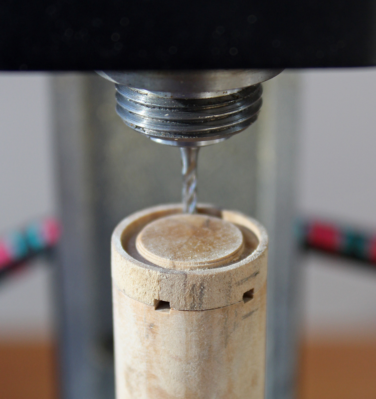
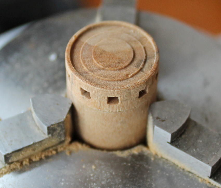
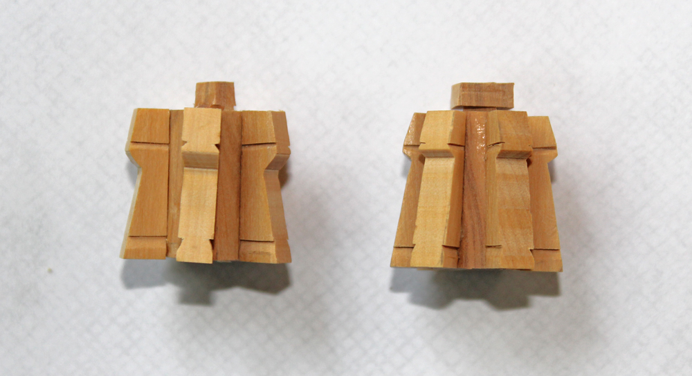
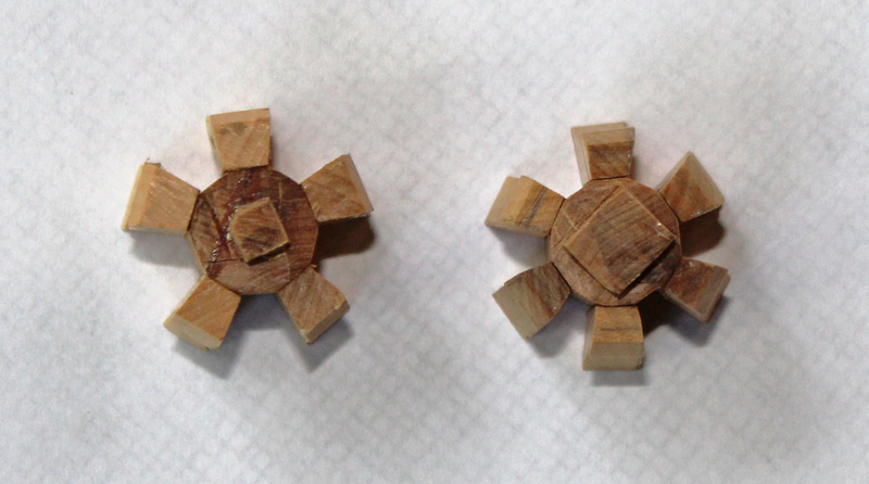
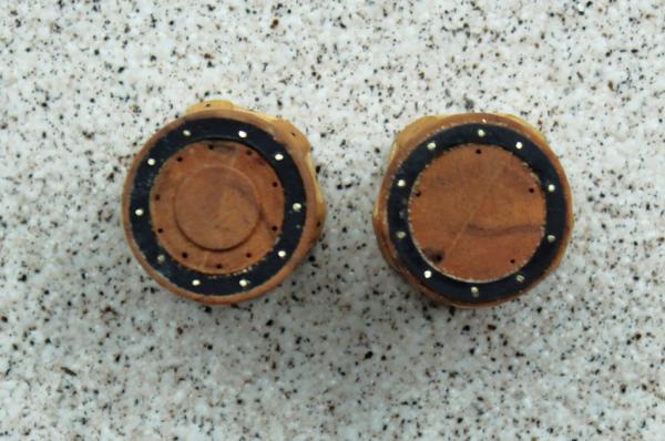
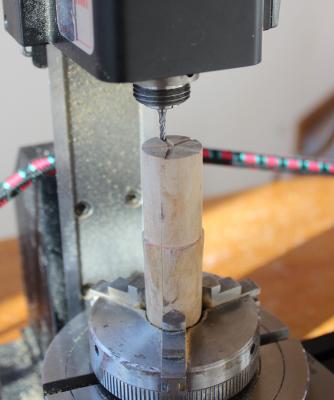
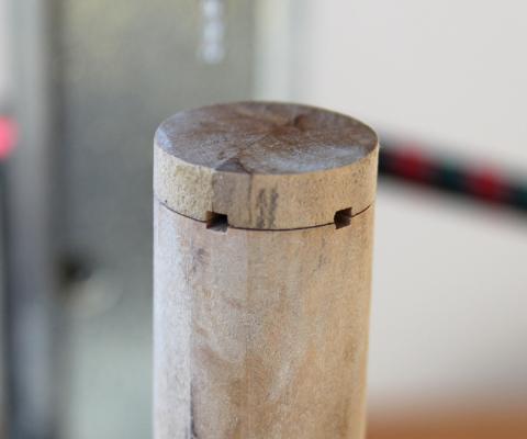
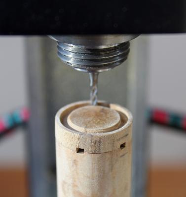
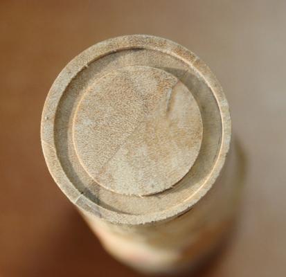
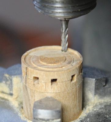
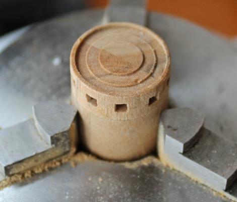
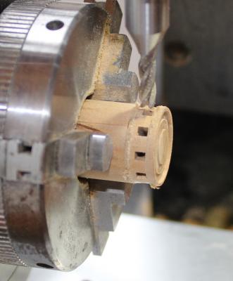
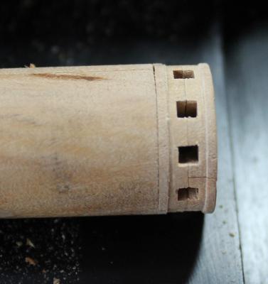
The next step was to make the drum heads. These were made from degame. My choice of this wood was simple... It was the only piece of wood large enough for the job. Degame is brittle to work with hand tools but machines well without burning. The drum head blanks are made from two pieces of degame glued together and turned to the correct diameter on the lathe. Slices were taken from the blank for the upper and lower halves of the drum head and then were glued back onto the blank for milling. The first task was to mill the slots for the capstan poles. There are five openings on the lower drum head and ten on the upper. The halves were then glued together and glued back onto the blank. There are recesses in the drum head for an iron reinforcing band. These were milled using the rotary table. The lower drum head is flat and the upper one has a second step milled to make it fancier. The side of the lower drum head is flat and the upper one is recessed. As a final step, the drum heads are glued onto their respective barrels.
-
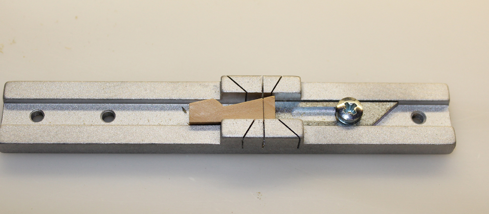
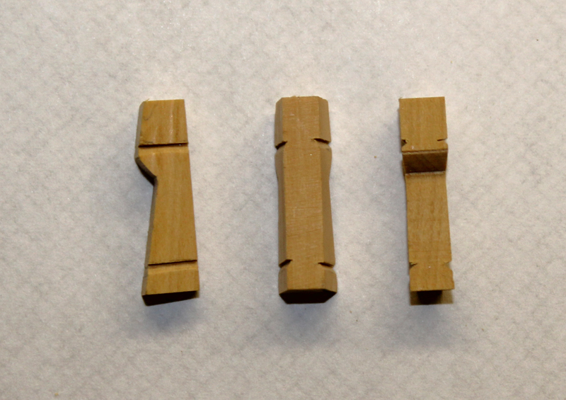
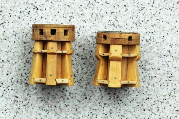
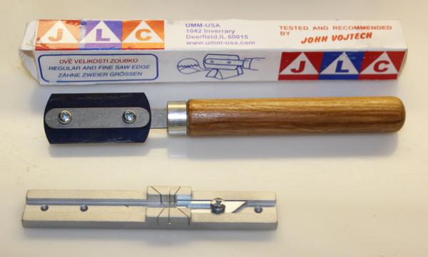
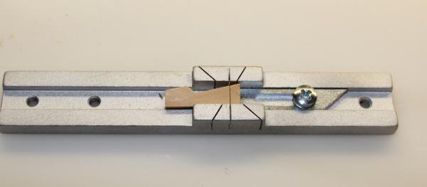
It has been a long time since any work has occurred on Atlanta. I finally had some time to dedicate to her this weekend. It is amazing what a surprise foot of snow will do to any outdoor plans! The next part of the capstan to tackle was installing the whelps. I have a little saw that I purchased at the NRG meeting in 2014. The blade is the size of a double edge razor blade and it cuts very easily through wood with minimal jaggedness at the edges. I also have a micro-miter box for it. The sides of the whelps are notched to accept the capstan spacers. I was able to accurately cut the top of the notch using the saw and micro-miter box. The rest of the notches were cut freehand. Now it was simply a matter of gluing the whelps to the barrels. After taking these pictures I realized that one of the whelps was not aligned correctly. It has since been corrected.


-
I am another one of the lucky ones who picked up my copy at the NRG meeting. Let me second Druxey's comments. It is a beautiful book, lavishly documented in color on heavy glossy paper. My only quibble is that the endoscopic photographs within the hulls are several years old. Camera and light source qualities, as well as the angle of non-distorted viewing through endoscopes have improved significantly since these pictures were taken. Hopefully the next volume will include some higher resolution photos.
-
When I built this model in the late 80's I was also frustrated with the quality of fittings and the method of constructing the deck houses. I ended up using the brass sheets in the kit and have never forgiven myself. I had only built two other kits, so scratch building was beyond my skill set at the time. I used Longridge extensively throughout the build. Basically, I threw out the Sergal instructions because of their inaccuracies. Although tiny and hard to read, the rigging diagram in the book correlates well with contemporary photos. I recognize your name from MSB. Remind me, please, when you were published and what you built. Good luck and please start a build log.
- 42 replies
-
- 1
-

-
- Cutty Sark
- Sergal
- (and 1 more)
-
2015 NRG Conference Update - MYSTIC
tlevine replied to Chuck's topic in NAUTICAL RESEARCH GUILD - News & Information
Thanks to all of the participants in this year's meeting. It is always fun to put faces to the names. Thanks, Ryland for the photos at Mystic. All of the speakers were outstanding. Grant Walker gave a fascinating presentation on the Rogers Collection. I was one of the lucky ones who was able to take home a copy of his book on the collection. I can hardly wait to start reading it. Other presentations included underwater archeology in the Black Sea, traditional Japanese boat building, 3-D printing and the restoration of the Morgan, as well as how-to round tables on various techniques. Hope to see many of you again (as well as more new faces) next year in San Diego. -
Don't confuse the Plans in the ordering section of Admiralty models with a complete set of plans for the ship one wishes to model. The Plans include a Mylar sheet which represents a generic Swan class sloop as well as a CD of the lofted frames. In order to model a specific ship, one needs to order the relevant plans from the Royal Museum. There are minor differences among all of the ships.
-
Congratulation on your milestone. The hull looks great. Be careful when sanding the port openings to keep the top and bottom parallel to the keel. In your last picture it looks like the bottom of the sill is angled up (perpendicular to the frame).
- 969 replies
-
- 4
-
-
- hahn
- oliver cromwell
- (and 1 more)