HOLIDAY DONATION DRIVE - SUPPORT MSW - DO YOUR PART TO KEEP THIS GREAT FORUM GOING! (Only 20 donations so far - C'mon guys!)
×


garyshipwright
-
Posts
927 -
Joined
-
Last visited
Content Type
Profiles
Forums
Gallery
Events
Everything posted by garyshipwright
-
 You very welcome Mark. druxey thats ok, and thank you. All is not lost and I will have plenty of photos of her as I was building her. I wished I had taken a lot when I was building Richard but other then the ones of her out side seems there is a lot of hidden detail in her and the only way to see what is there is to either see one being built or looking at her drawings. Gary
 -
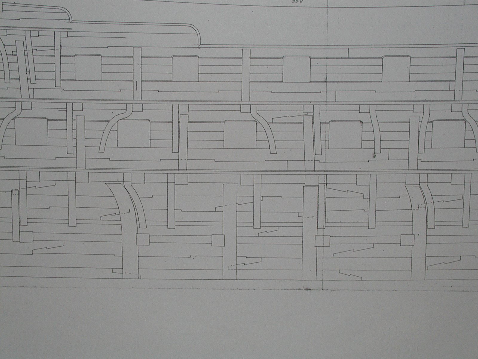
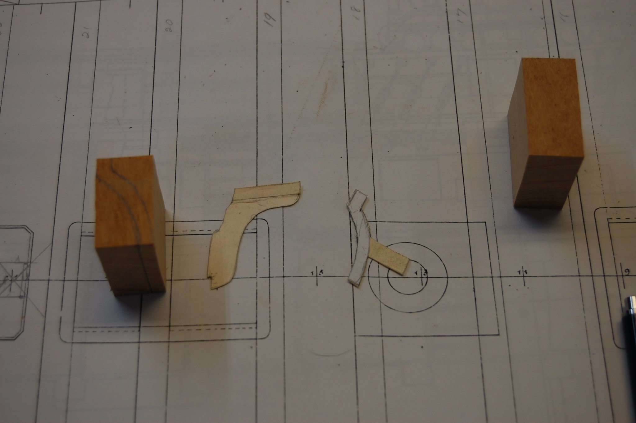
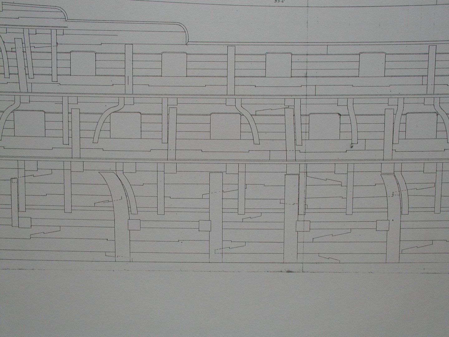
Sorry Mark. Seems when I started a new log after the other one disappeared I didn't replace them and will add some here. I followed the Berwick plan which seems she is about has close as I can get to how Montagu was built. When I did the ones at the bow I made up a jig the curve shape of the bow timbers from templates and steamed them in a plywood jig. Gary


- 835 replies
-
- 12
-

-
Mark you could look in to getting some dental tools that might be small enough to help you do the carving. Gary
-
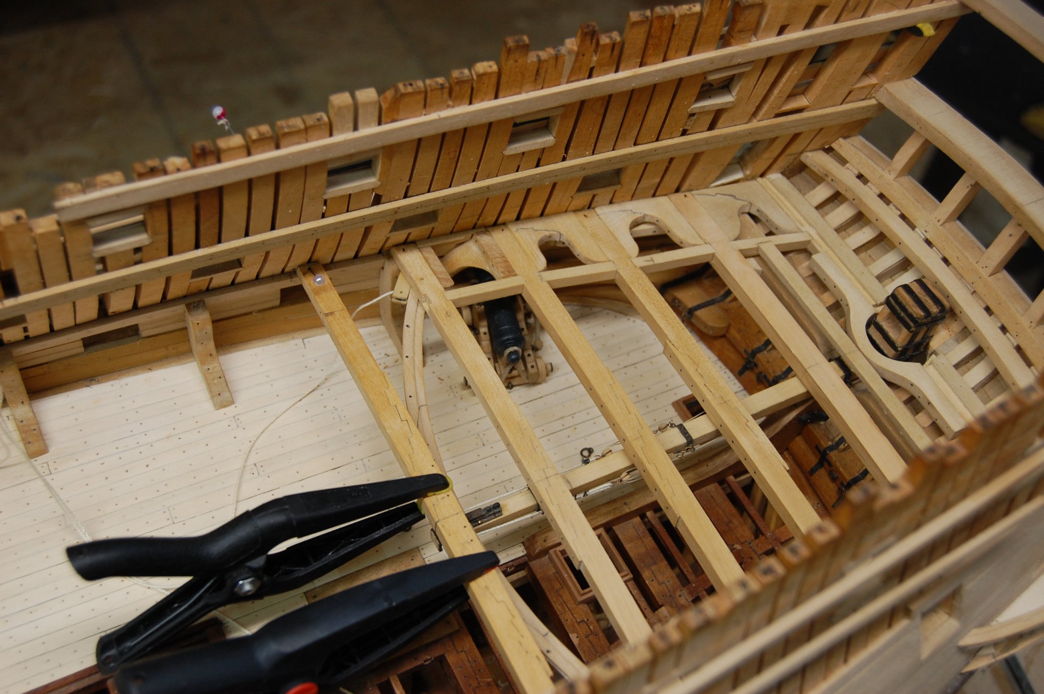
Thanks every one and the happy birthday's and comments are well received. Greg thought I would let you know but the rudder does work and moves from stbd to port. I probably will put in a stop some place which should prevent me from wanting to put it in the tub and take it sailing. Well maybe not the tub. Ed, this is one of the more interesting things I have done on her along with tackles for the gun port lids that you can see in the photo's. Once again thank you folk's and hope to have another up date before my next birthday. 🐵


- 835 replies
-
- 21
-
-
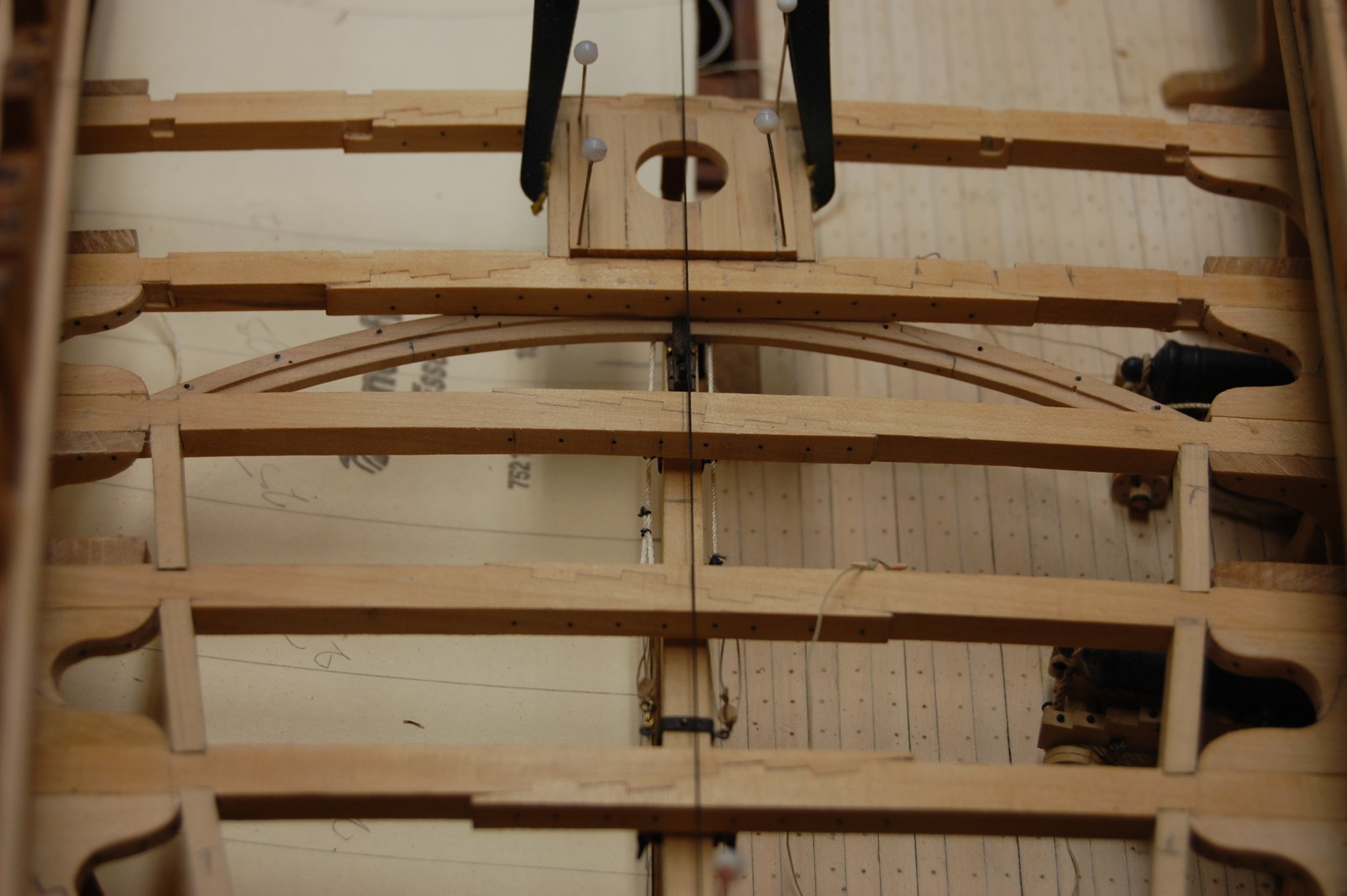
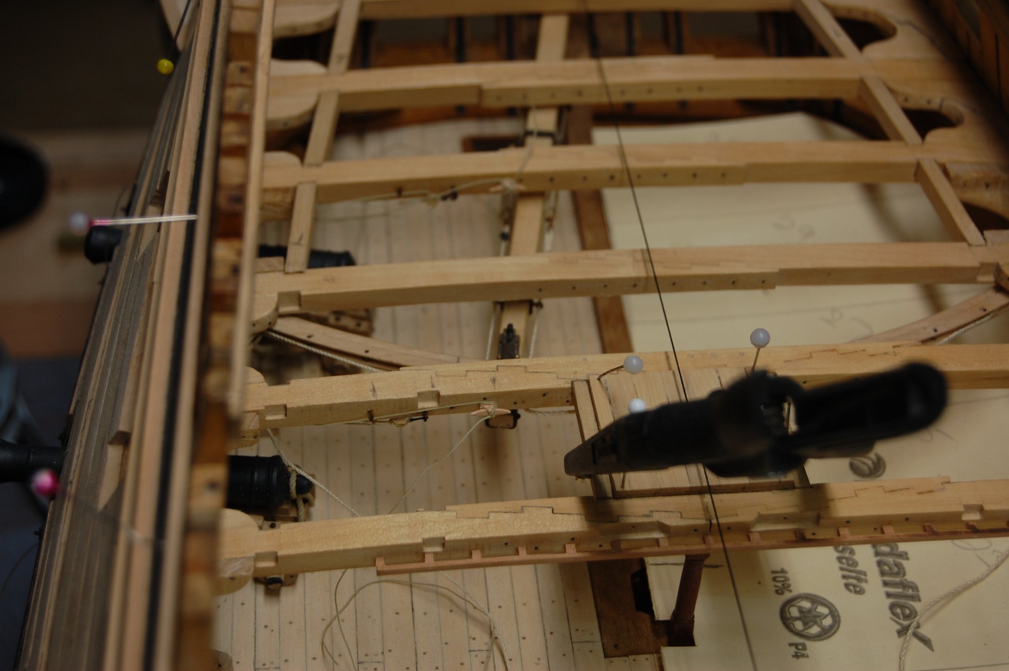
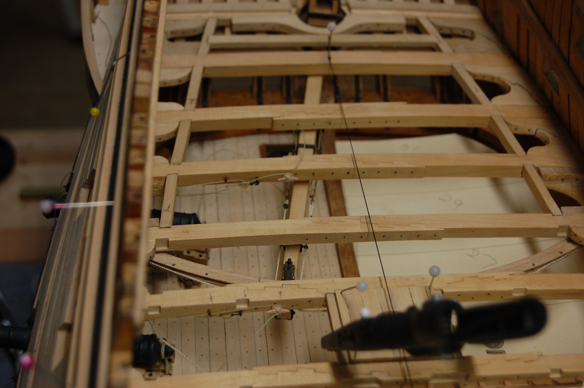
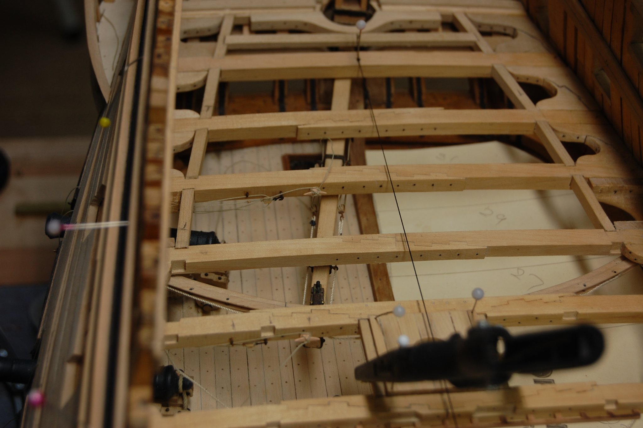
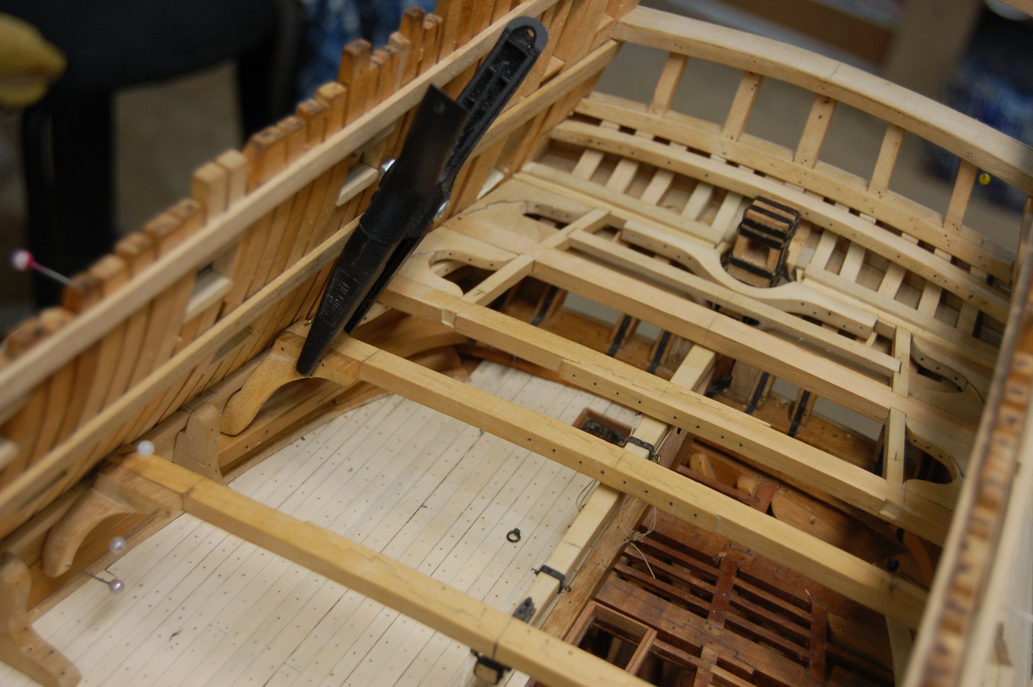
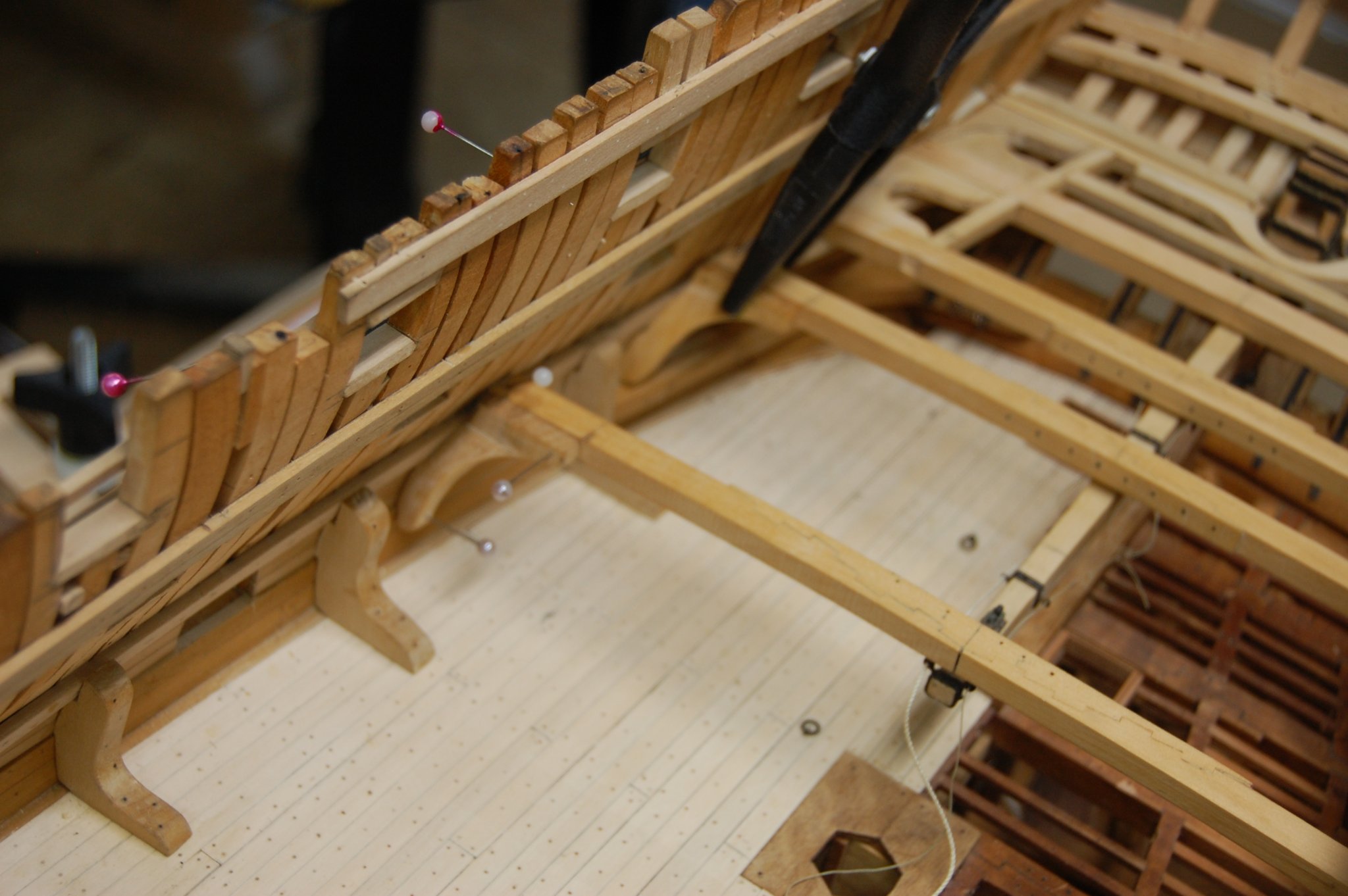
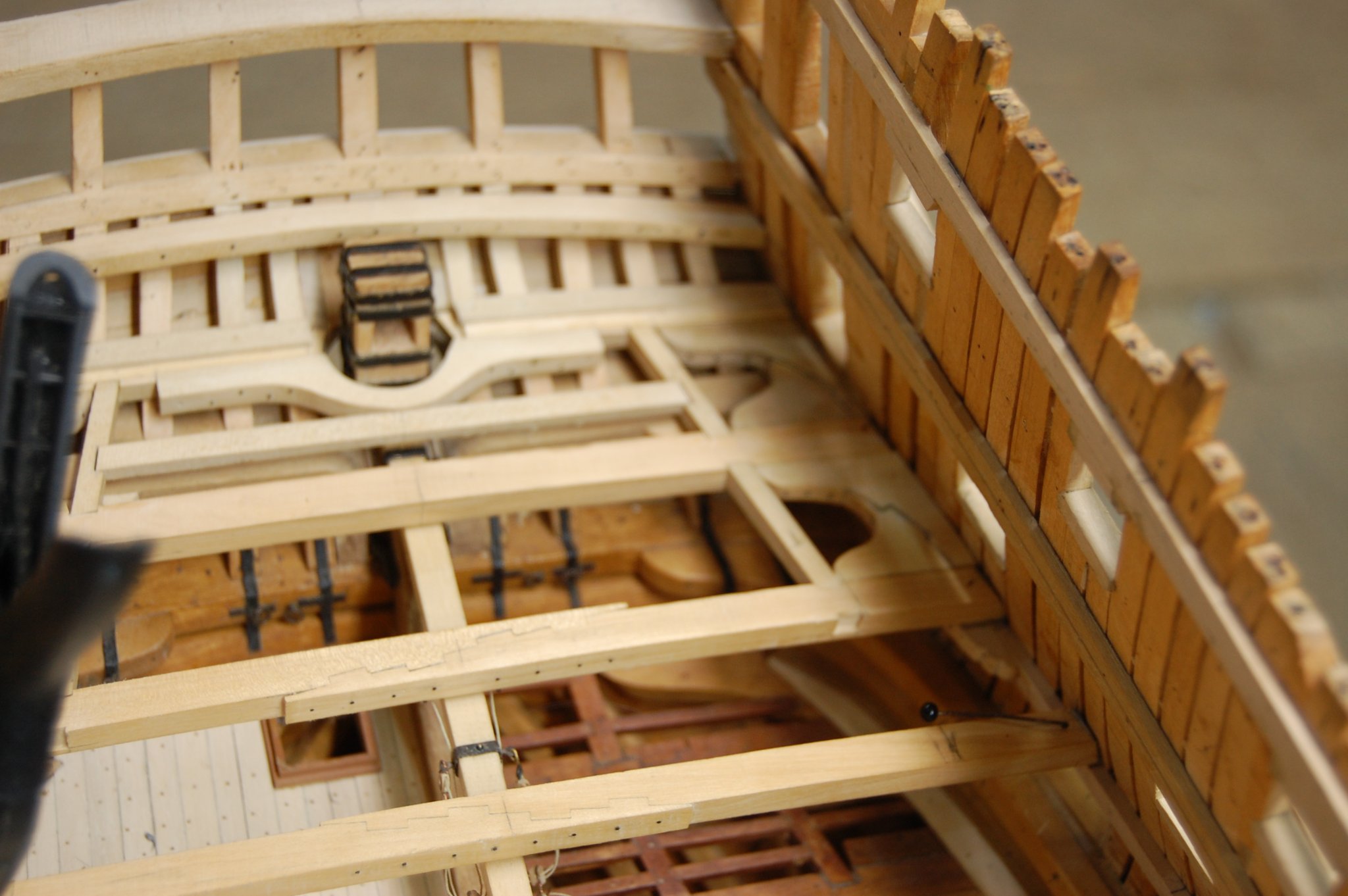
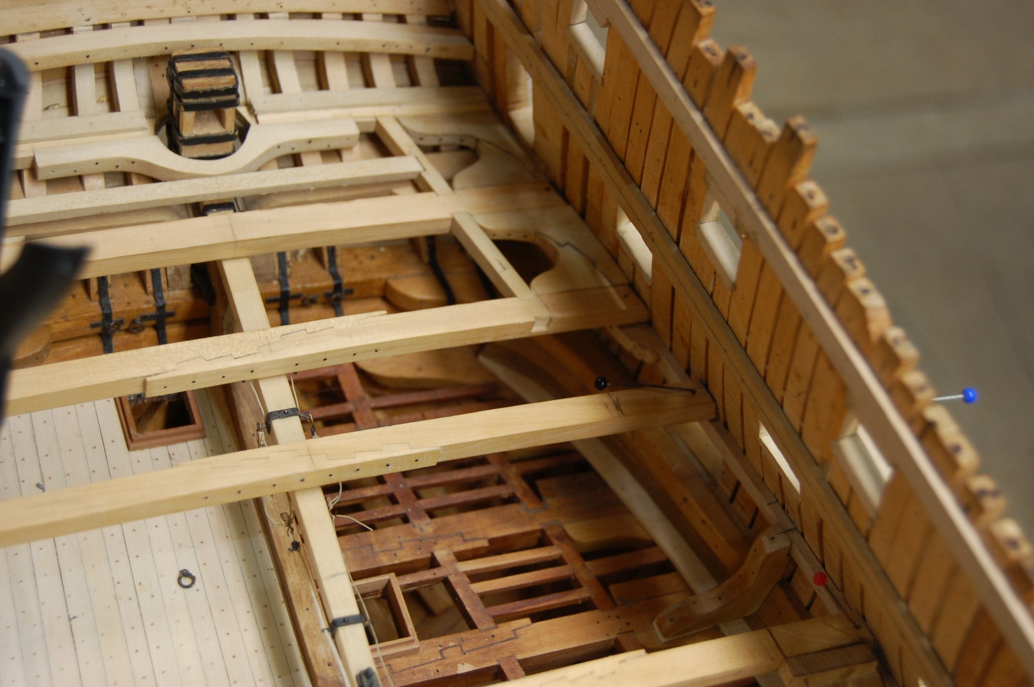
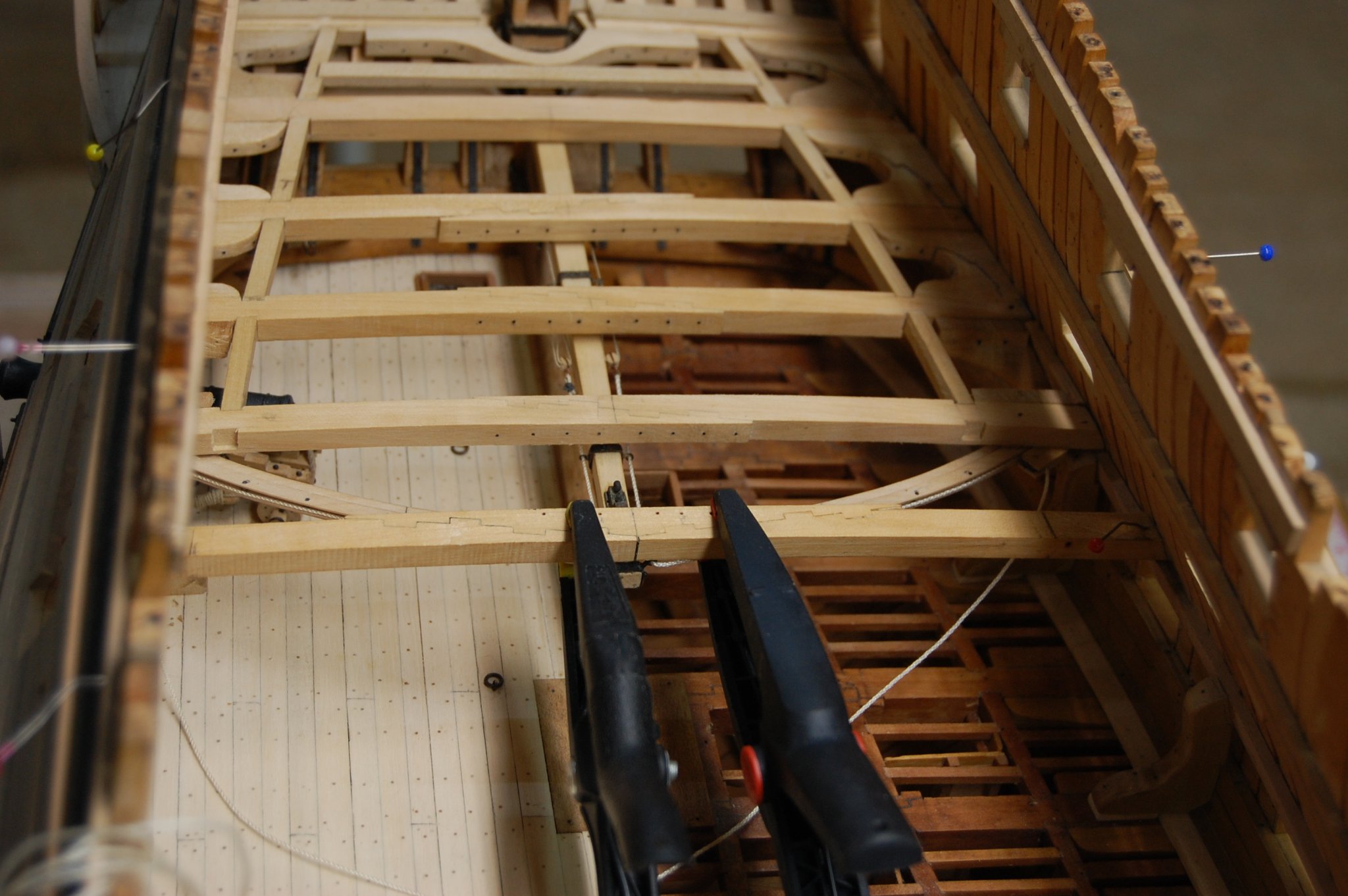
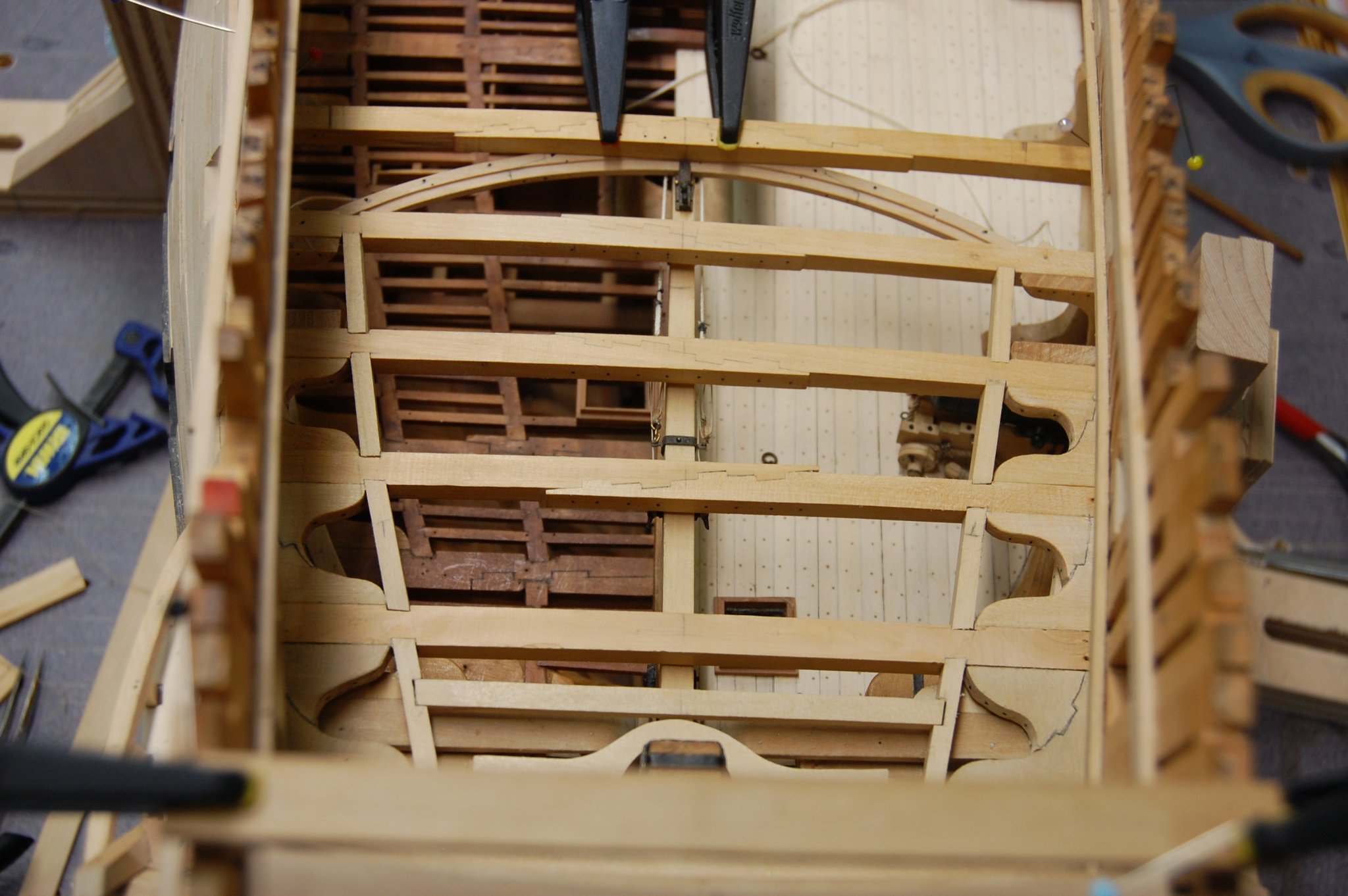
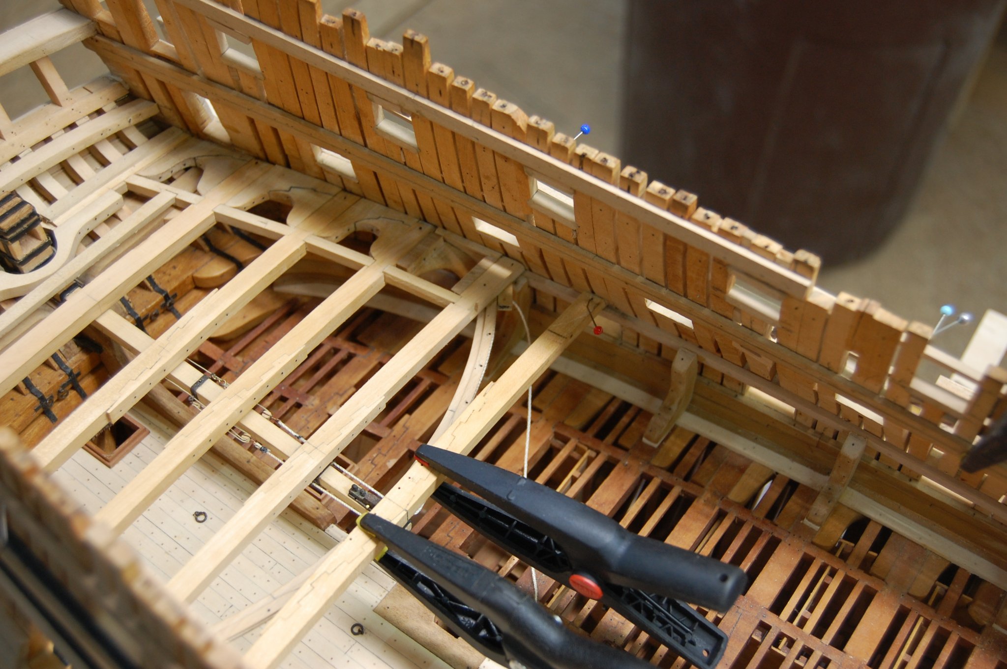
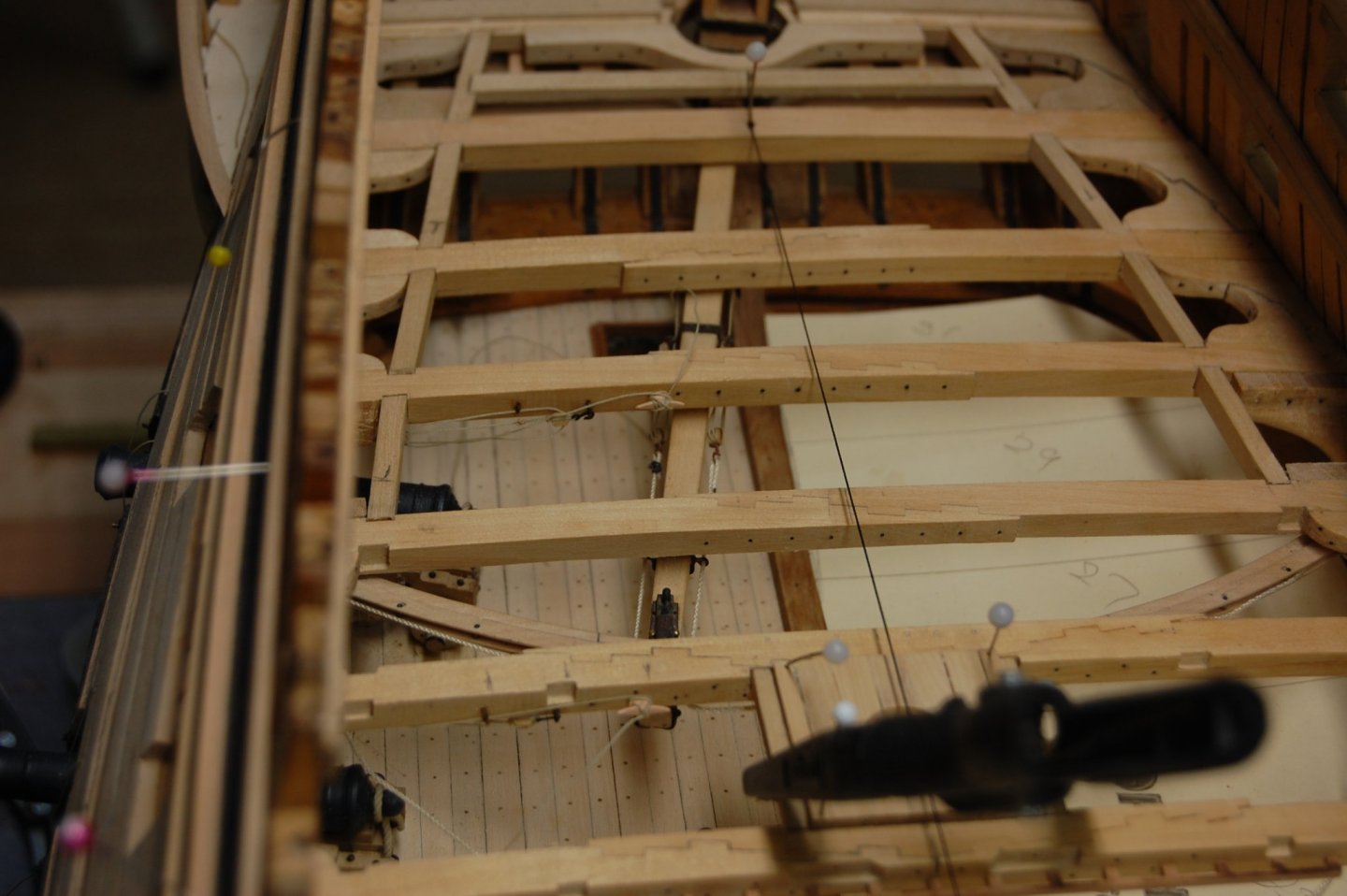
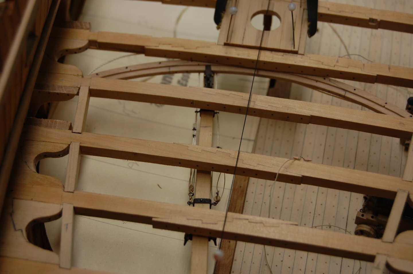
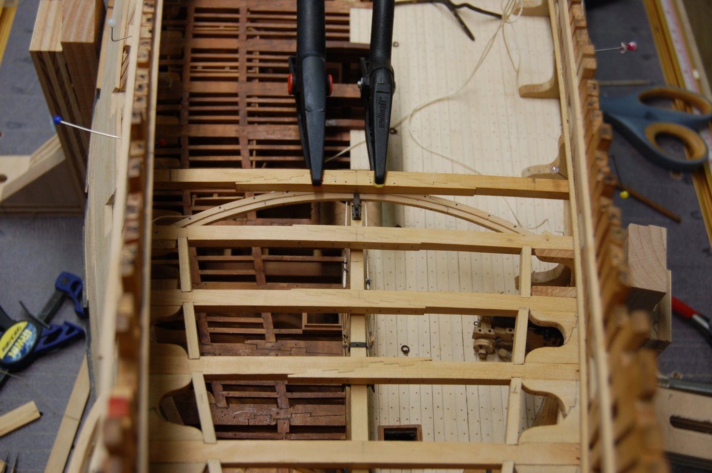
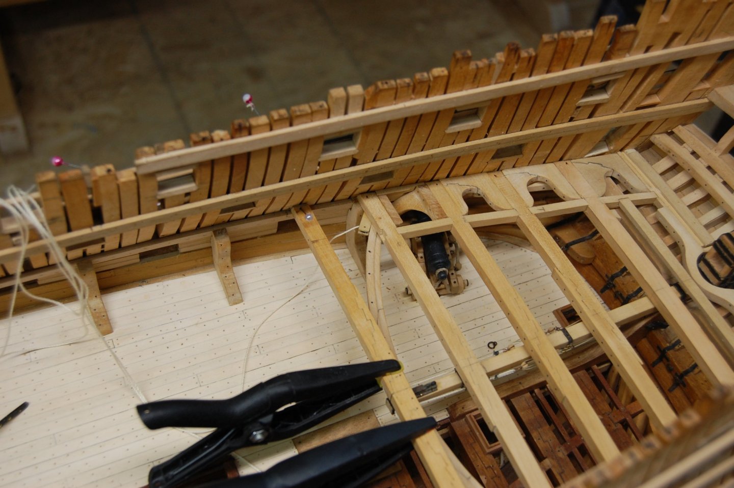
Hi Guys. Being that today is my birthday, figure I would do a small update. This time its on the upper gun deck along with the tiller and the track which it runs in with making and installing beams, hanging and lodging knees that has to have a cast in them so they clear the gun ports. As I said some place you have to fit 3 to four parts in place temporary in order to glue one part in permanently. Doesn't seem one gets much done but has long as you are enjoying it or cares. Thanks guys hope you enjoy the photos.


- 835 replies
-
- 19
-
-
Shoot Mark, wait till you get to the curve knee's of the upper deck, its a lot of fun. At least the planking is on the out side. Working in side the hull is a back breaker. The gun ports on alfred took me am thinking around 10 years give or take another 5 years. At the moment am working on adding the tiller and sweep and the upper deck beams which seems in order to go one step forward you have to work on two to three beams get them all notch out and finally glue one in place but still it is a lot of fun. Gary
-
Mark, Fincham's says in his book, Fincham's Ship -Building, Port Stops are the ends and edges of the planks left round the ports, from one and a half to two and a quarter inches from the sides of the timbers and upper and lower parts of the sill, to receive the port-lids and half -ports. You can find this on page 138 reprinted by the Ship Model Society of Rode Island 1933. Sounds like the stops no matter what deck they were on was always a inch and half to two and a quarter inches. Gary
-
Hi Johann. You know your setting the bar very very high and I for one really enjoy watching your build. Keep up the great work sir gives me something to shoot for. Gary
-
Looking good Mark. Keep up the good work sir. Gary
-
Thanks guys your comments mean a lot to me and to all the likes to. Gives one the small slightly push to keep going , that is untill the misses says go cut the yard sweetheart,its getting a little tall. ;o) Gary
-
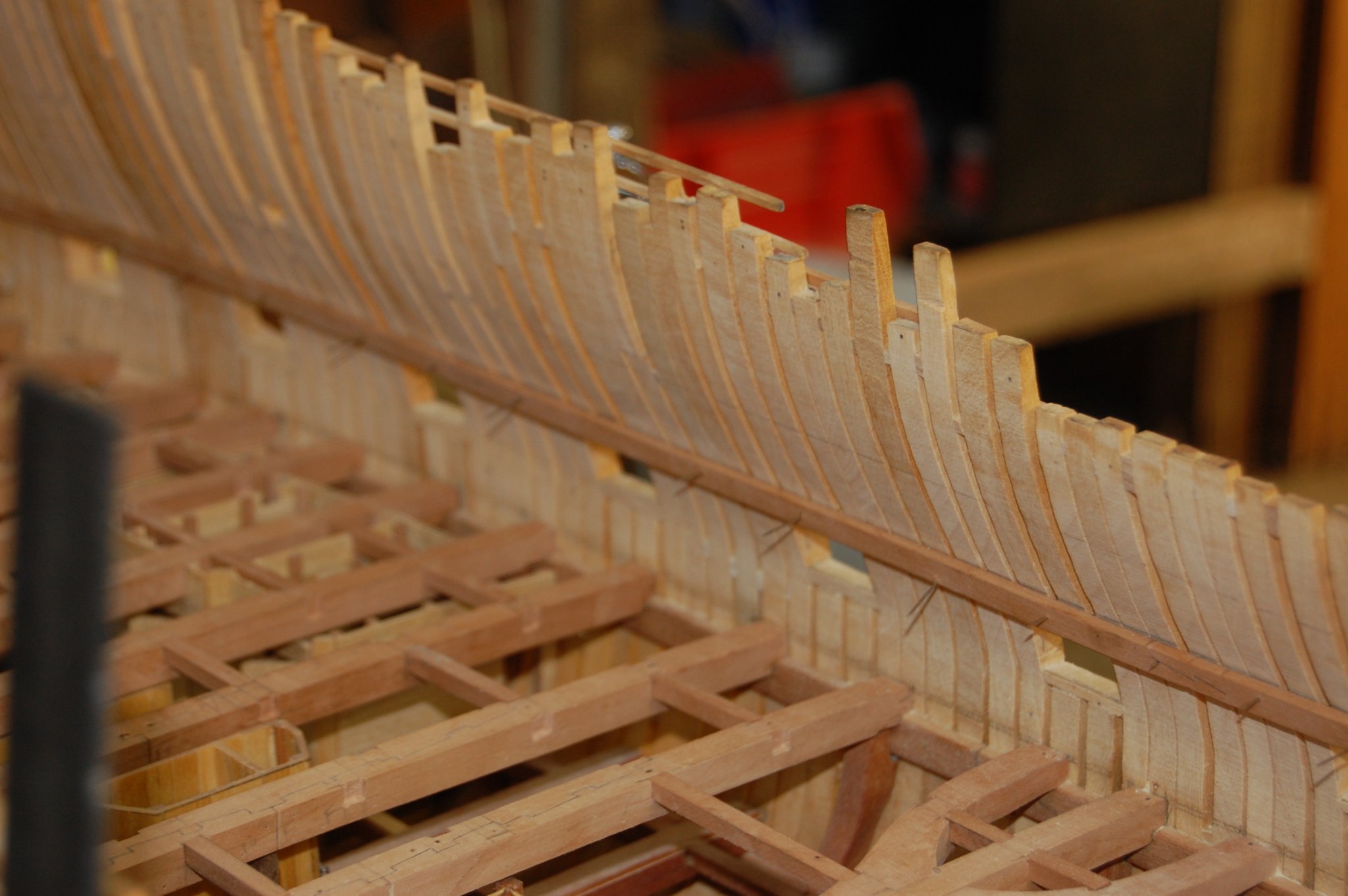
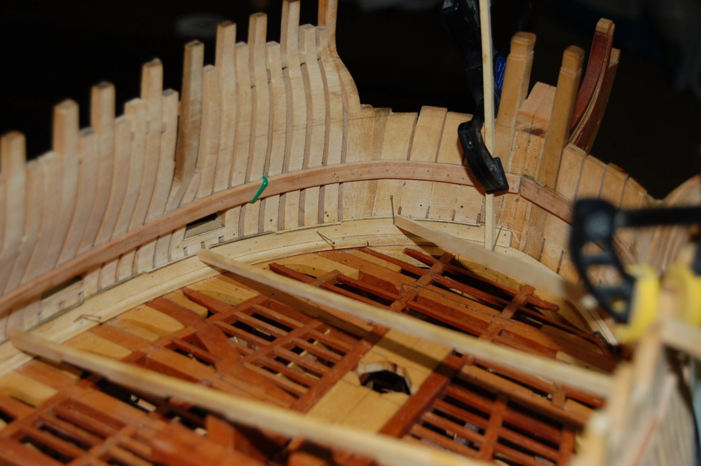
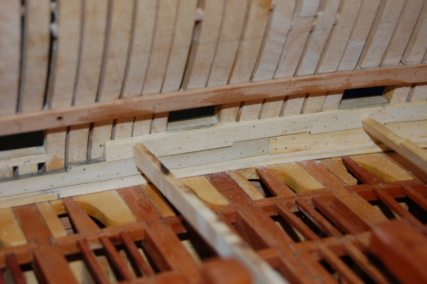
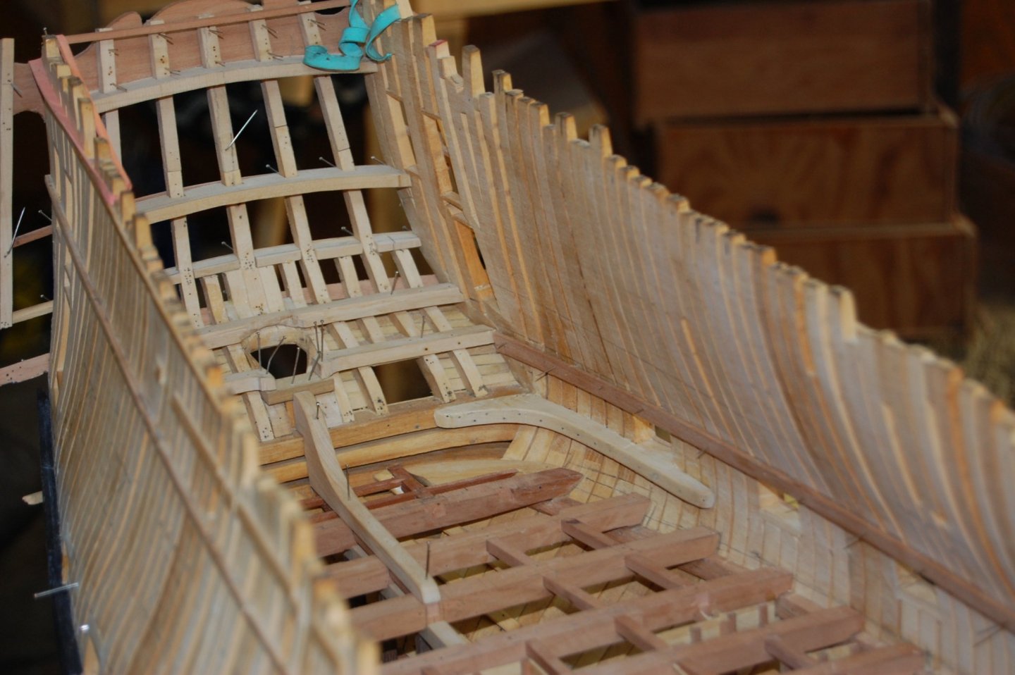
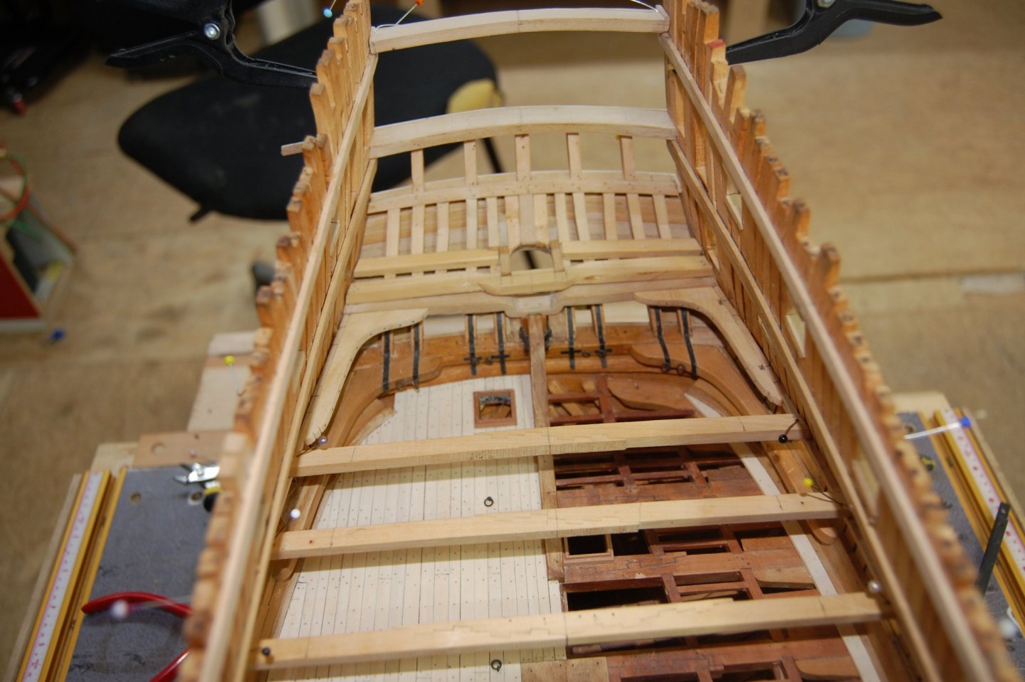
Hi guys. Been awhile since my last update and after retiring I seem to be spending more time in the shop, that is until the honey do's come calling. Here is a small up date on her Hope you enjoy the photo's. Gary

- 835 replies
-
- 25
-
-
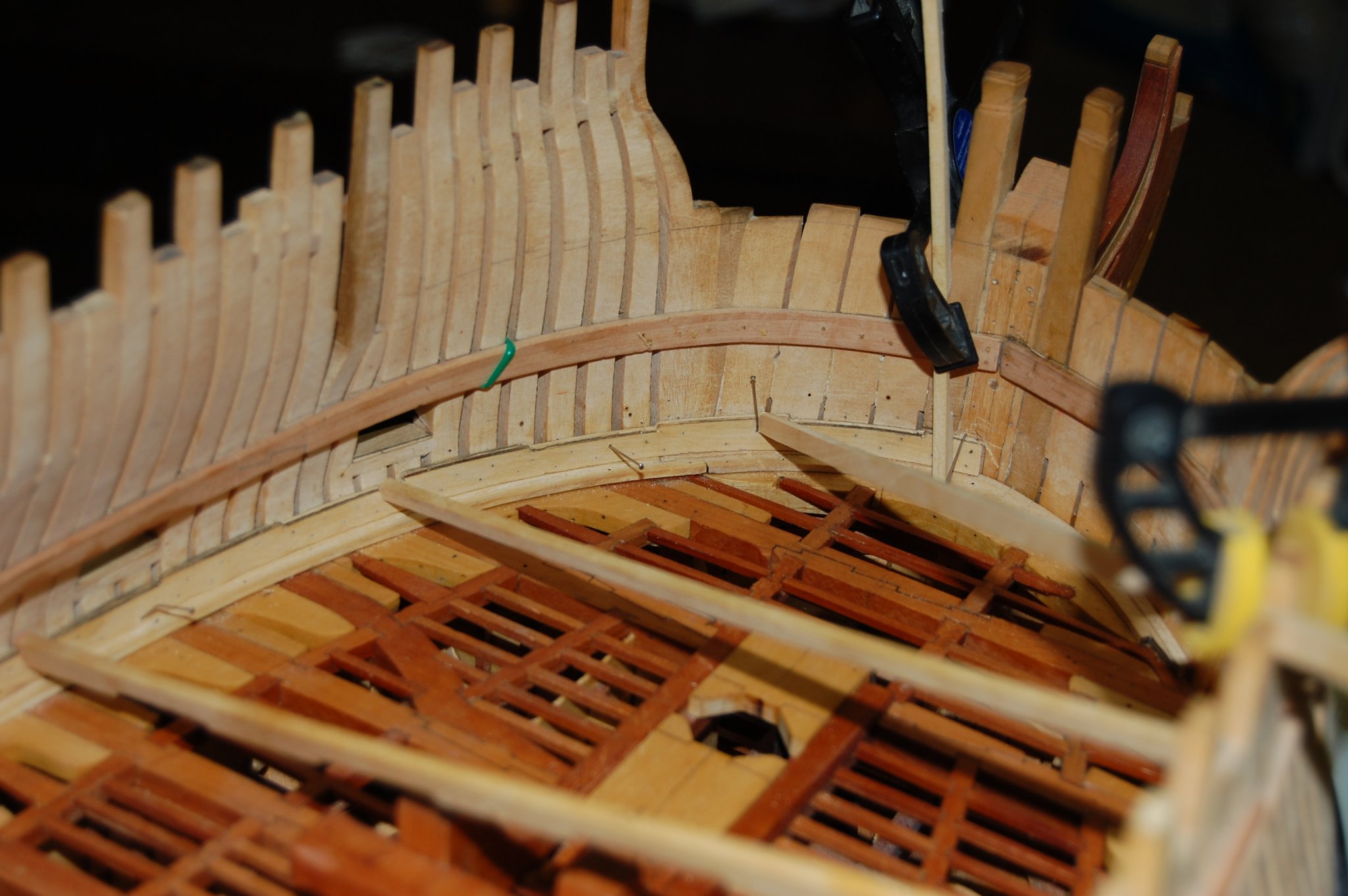
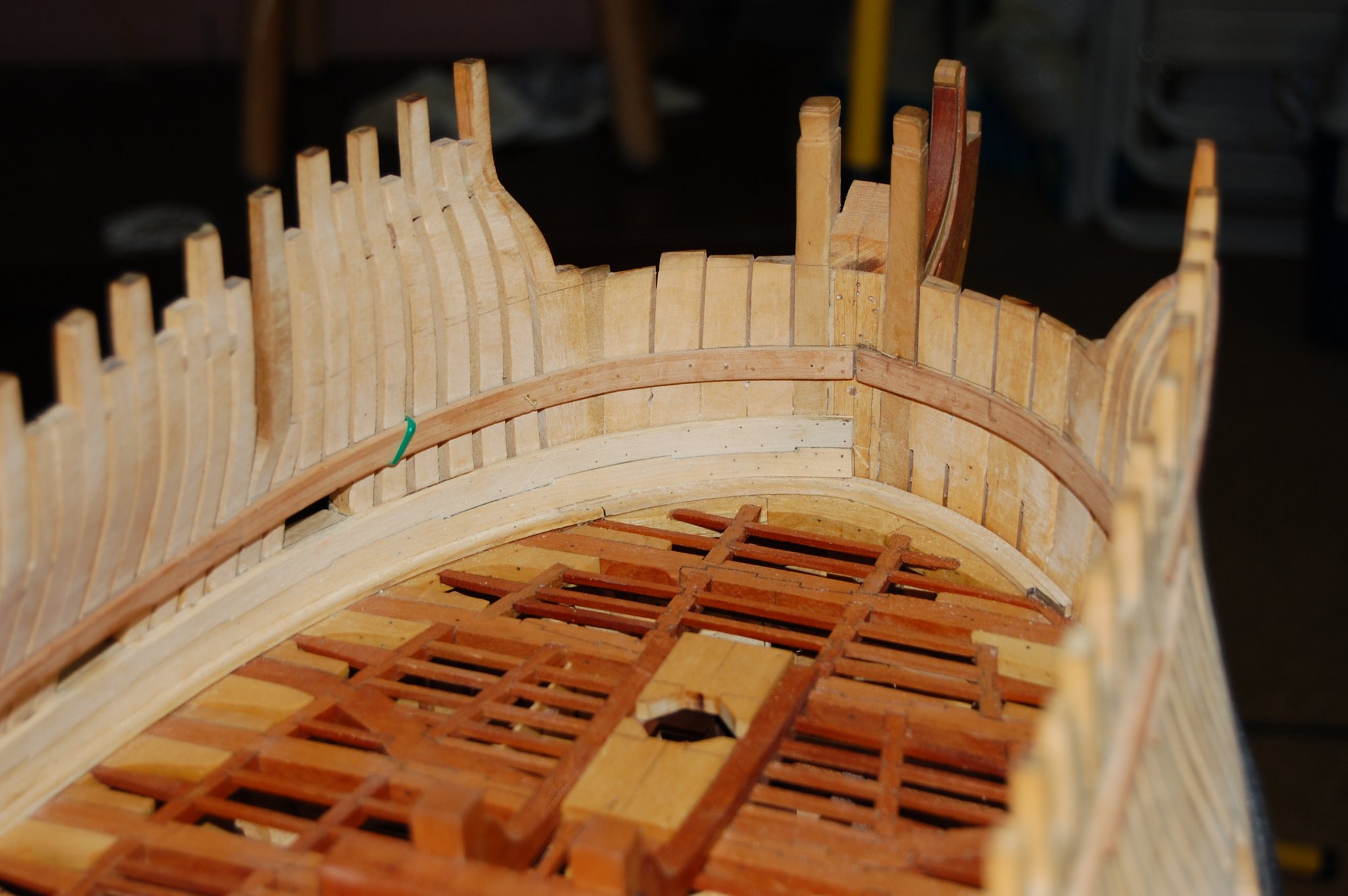
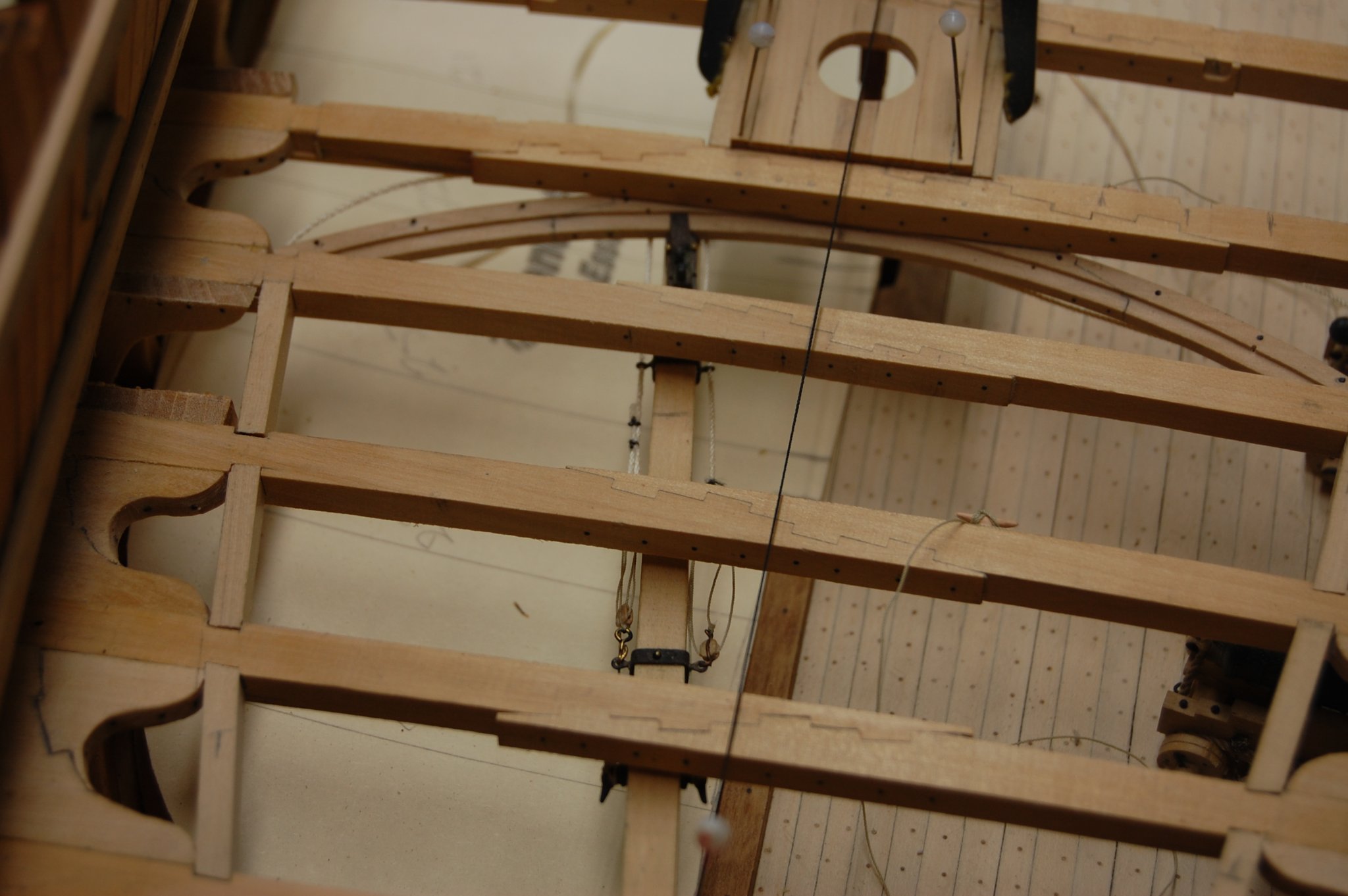
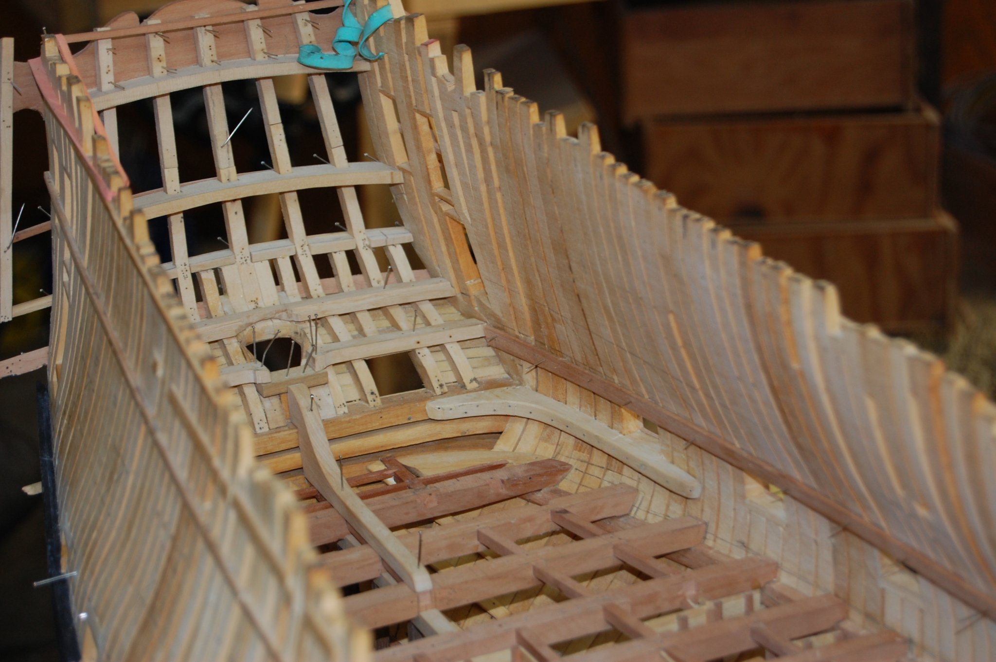
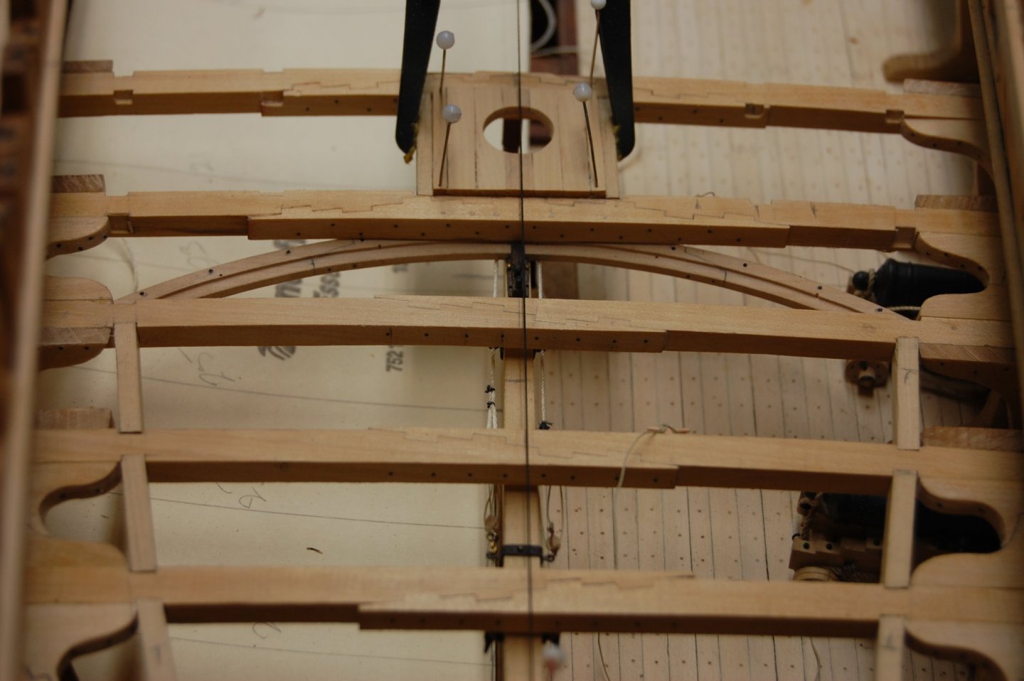
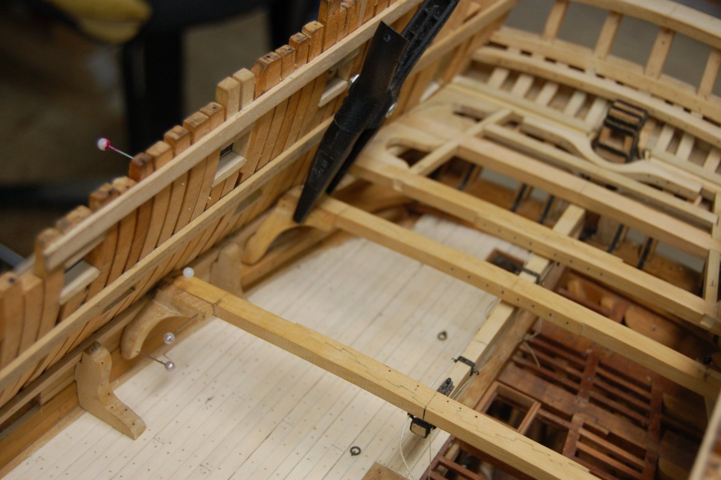
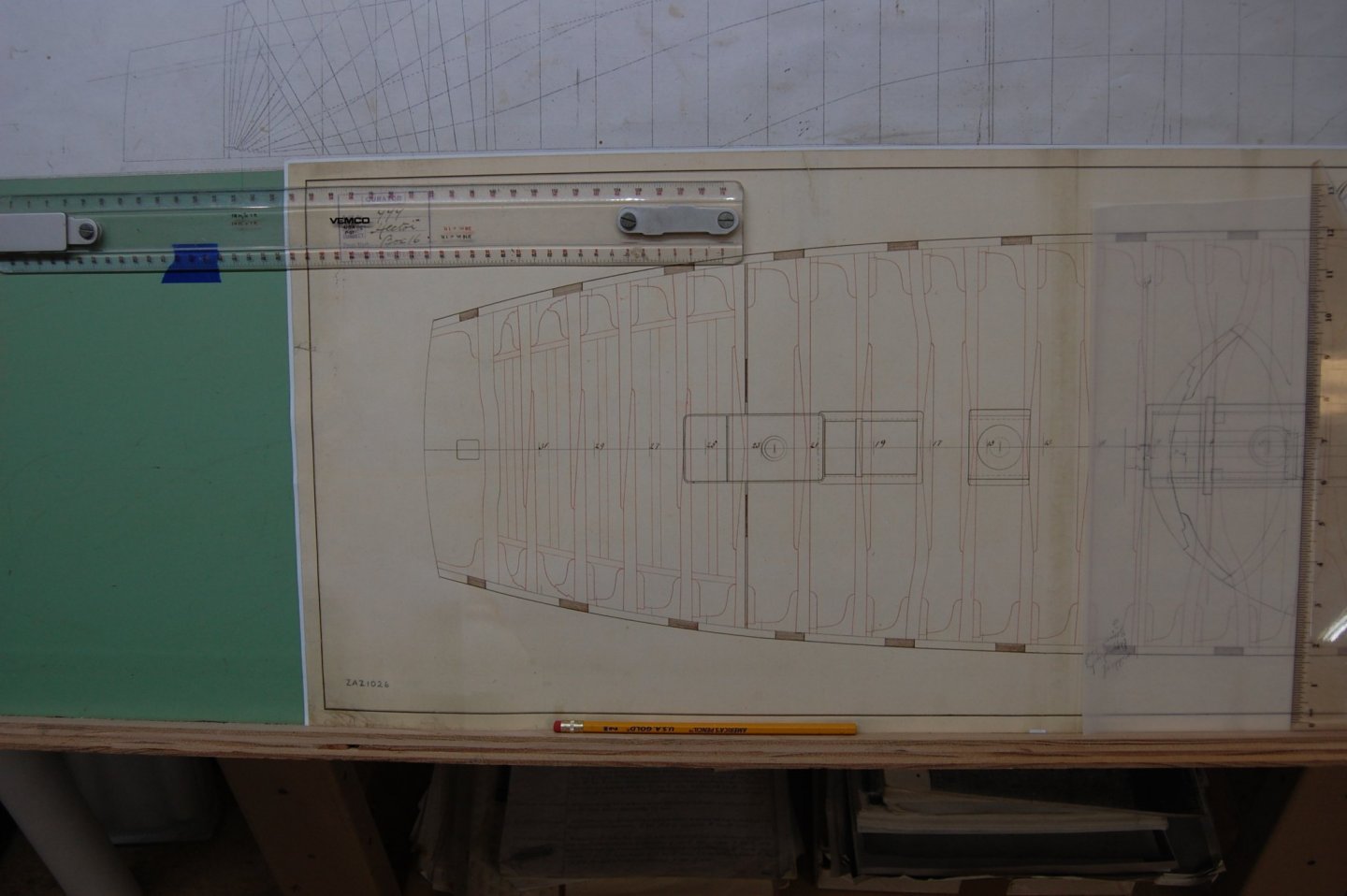
Hi Mark As far as the curved beam in front of the rudder in post 1589 of your log, that will work just fine, its behind the rudder head that causes the headache. I believe mine is similar to yours and comes from the Hector upper deck plan. As soon as my camera gets a full battery I take a picture or two of it. I do believe that they would have done something like what Rekon 54 show on his Le Feuron. Another way that would of worked and probably was used, was to installed half beams with rabbets on the leading edge on each side of the rudder head. Information or the French way can be found in Boudriot 74 gun ship. Now you say, well this is a english ship but the first true 74's came from the French so I don't think am to far out in left field. Beside I have not found a better more accurate way and if there is am all ears. You will find Rekon log on page 7 and the photos are on page 12 of his build. The post that show the batten I was talking about is the 3rd photo in post 347, 10 photo in post 358, and photo 6 in post 359. Let me know please what you think good sir. Mark I got a couple of photo's for you. This part is still a work in progress so forgive me if every thing is not square. Gary
-
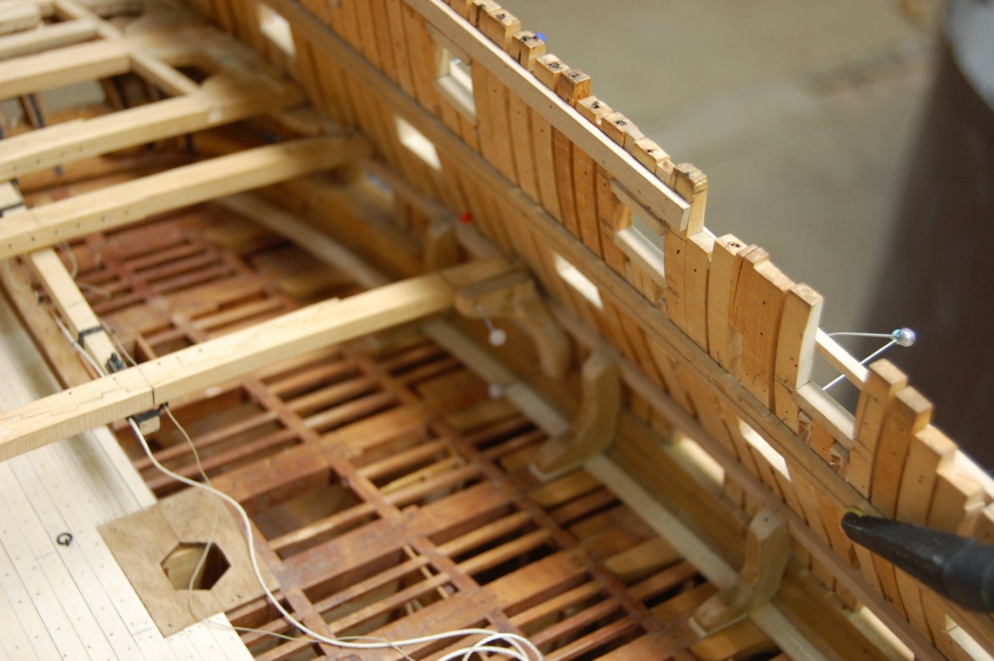
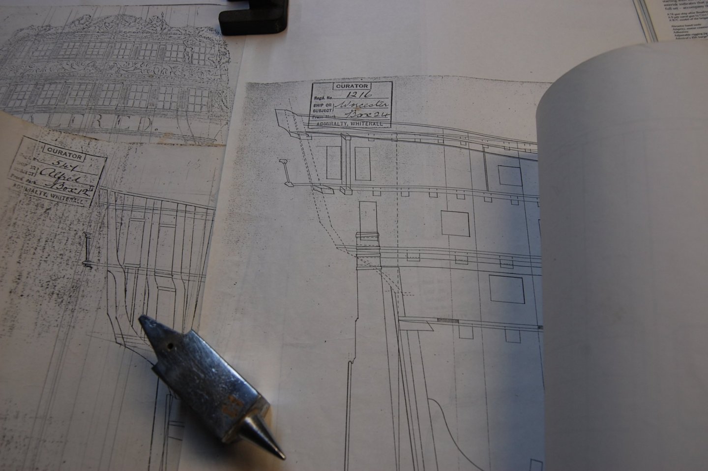
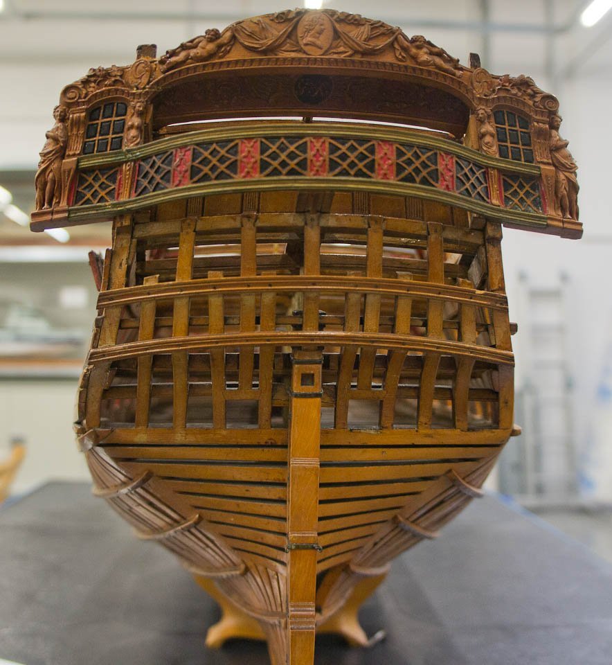
Hi Mark . Think I found some thing researched wise on the stern that I thought you may be interested in. For the last week maybe longer I have been researching the upper deck transom to install one in Alfred at beam level for landing the end of the planks on. After trying for a few days to using the measurment from Steel and the Repository and a few others like NMM plans, I had to cut out a good section of the middle of the transom which didn't make sense. Also to make it fit height wise for the planks to lay level in the rabbit along the front edge, lots of wood had to be trimed away. Steel says it was post to be I believe 13 inchs in the middle. Well lets just say that didn't work to good. Your photo of the original model doesn't shows a transom behind the rudder as you show in post 1597 and 1599. The photo of the original model doesn't show a solid transom going all the way across the stern timbers, at deck level, going behind the rudder untill you get higher up which I believe is the bench transom. I have been trying to figure out why the space from the last beam on most plans don't show any thing beam wise after the last beam , like a transom against the stern timbers like you did. I believe that the space behind the rudder was to tight to fit a transom, and after you trim off the wood to make it fit for landing the end of the planks you would have cut most of you strength away. Also when you look at the Plan 's in the NMM , one thing you will noticed is that when they drew out those plans every beam and deck transom was shown on the plan 90 percent of the time. So the question kept coming up, were is that transom. Most plans don't show a upper deck transom behind the rudder because there wasn't one, which is why there is such a empty space from the last beam in front of the rudder till you get to the stern timbers. Alfred showed me that one could not be fitted. I have seen plans showing a beam/transom that wraped around the rudder from the front that was attached to the stern timbers if you want to see it. Now you ask, what did they land the deck planks on past that last beam. I believe what they did was install a batton or half beams one per side with a rabbit in the fwd edge, across the stern timbers for the ends of the planks. Not quite as hefty as a transom but do believe that this was hefty enough to do the trick. There really wasn't any weight back here but they may of reinforced the planks with carling's and ledges underneith it. The only plan that I have seen with a transom behind the rudder was in Steel and that is a 80 gun ship. Maybe by the time of Steel who knows, maybe they increased the space to be able to fit a transom
-
HMS Warrior 1781 by John Rose
garyshipwright replied to John Rose's topic in - Build logs for subjects built 1751 - 1800
Hi John. Nice job sir. She is looking outstanding. Gary -
Thanks druxey. It would be nice if somebody wrote a book on building one. Know any body by chance. ;o)
-
Hi Mark thinking that I miss something back here. After looking at your drawing some of the items make sense such as the curved deck beam in front of the rudder. On Alfred upper deck plan does not show this beam so I did a little digging and Steel and other's say the upper deck had 28 beams but Alfred plan on shows 27 with a some what big gap from the front of rudder to the back of the last beam. Seems to me I found my missing 28 beam. This curve beam does't show up on the sheer plan but shows up nicely on the deck plan of the Hecter. Any way need to do some more research and a little deconstruction on a couple of item if need be Thank you sir. Gary.
-
Hi Mark. Just to let you know sir, druxey is a big help in getting us through the in's and out's of the stern and every thing that goes to build this part. Will be watching your progress as we go. On a different not back a couple you talked about the chocks and other items aroun the rudder head and may use this in Alfred, with you permission that is. Being there really isn't any real evidence to show other wise on her. That and a little artistic licensing that is. ;o). Keep up the good work. Gary
-
Hi Joe, Ron and Zhuying and thank you for your thoughts about this and may take me some time to figure this out. Am very much a newbe at this and has given me a lot to think about. Might take me a little time but seems I have a little of that now. Thank you good sirs. Gary
-
Thanks Mark
-
Hi Mark and thank you. That was one of the items that I was most concerned about, taken away the capability of the hand wheels and its manually use. Am not sure about other ones but you can still use the hand wheels by just unpluging the steeper motor from the drive box and now you don't have a feed back ,in to the drive box unlocking the handwheels for manually turning. Some say if your not going to use it for cnc why have it. Seems one now has a choice to use either manually or cnc. I also found that you can reuse your dro and handwheels to keep track of where things are out so you don't have to count turn's, which suck when its a long or deep part. Being able to still use the DRO with out the computer hooked up gives you all the capabilitys you had before adding steeper's. Because learning how to use cnc takes a bit, its nice to still have the manually part. Gary
-
Hello everyone. I am planning on changing my Sherline manual mill over to a CNC mill and looking for the good and bad in doing this. Its a little on the costly side I know but would like your insight in to what you guys think and what you guys did or didn't do. Of course I might just be tired of turn the hand wheel. ;o) Thanks. Gary