Hubac's Historian
-
Posts
3,305 -
Joined
-
Last visited
Content Type
Profiles
Forums
Gallery
Events
Everything posted by Hubac's Historian
-
 You can, but just not within the post. Or, at least, that's what appears to me when I visit other build logs, as well as my own. The like button activates, when you press it, to indicate that you have liked the post, but you can't see who else did, particularly while in someone else's build log. In the past, I might browse through logs and eventually follow them when I see that those logs are attracting modelers whom I admire, or with whom I share modeling interests. To me, it was sort of like the way Pandora finds music for you; "if you like this, then try this..."
- 608 replies
-
- 1
-

-
- la couronne
- corel
- (and 1 more)
-
Just surfing along ona slow day... Great looking model, Don! Beautiful detailing throughout, and your ship's boat is a model within the model. Really excellent work!
- 653 replies
-
- 4
-
-
- trabakul
- marisstella
- (and 1 more)
-
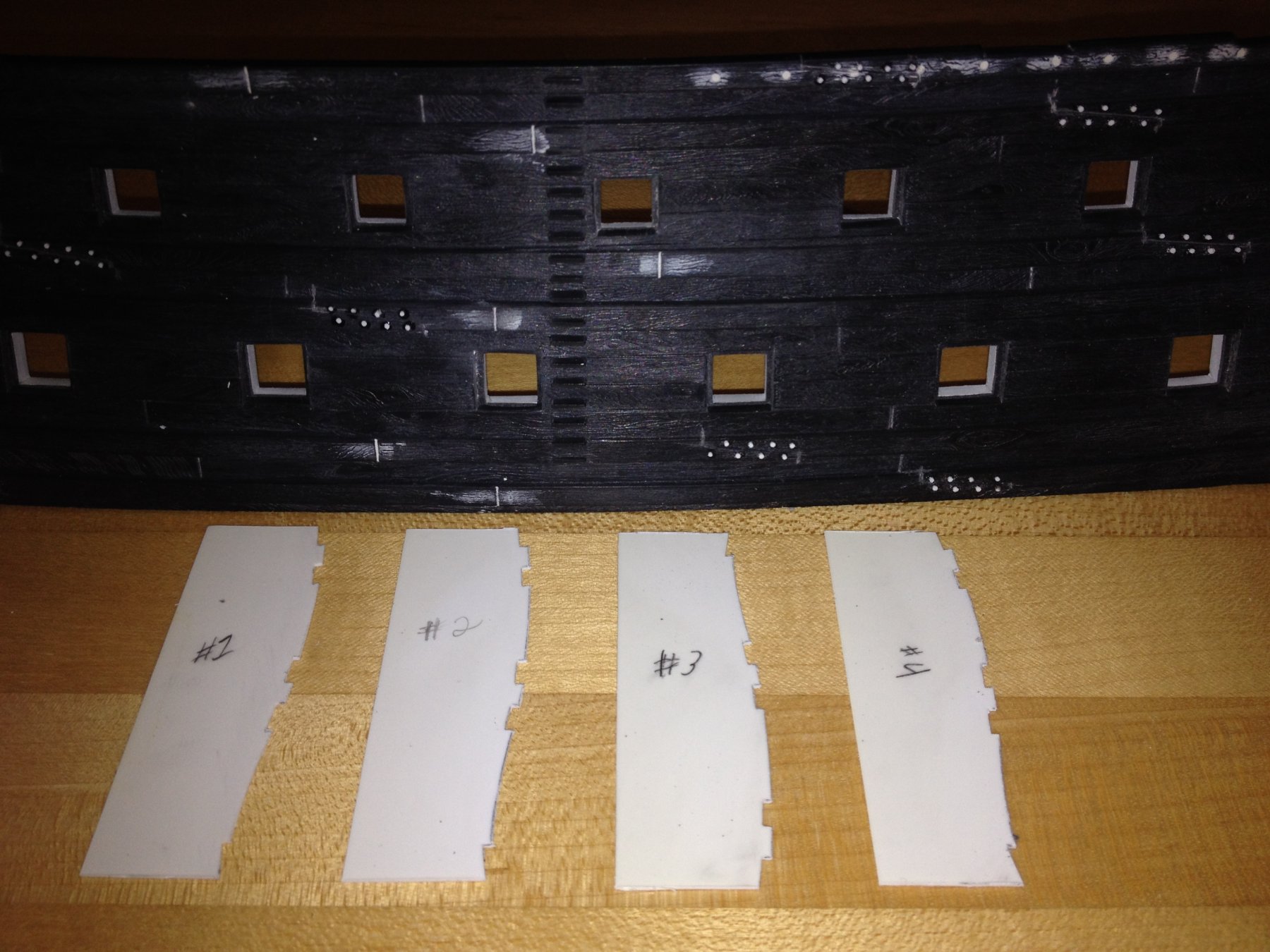
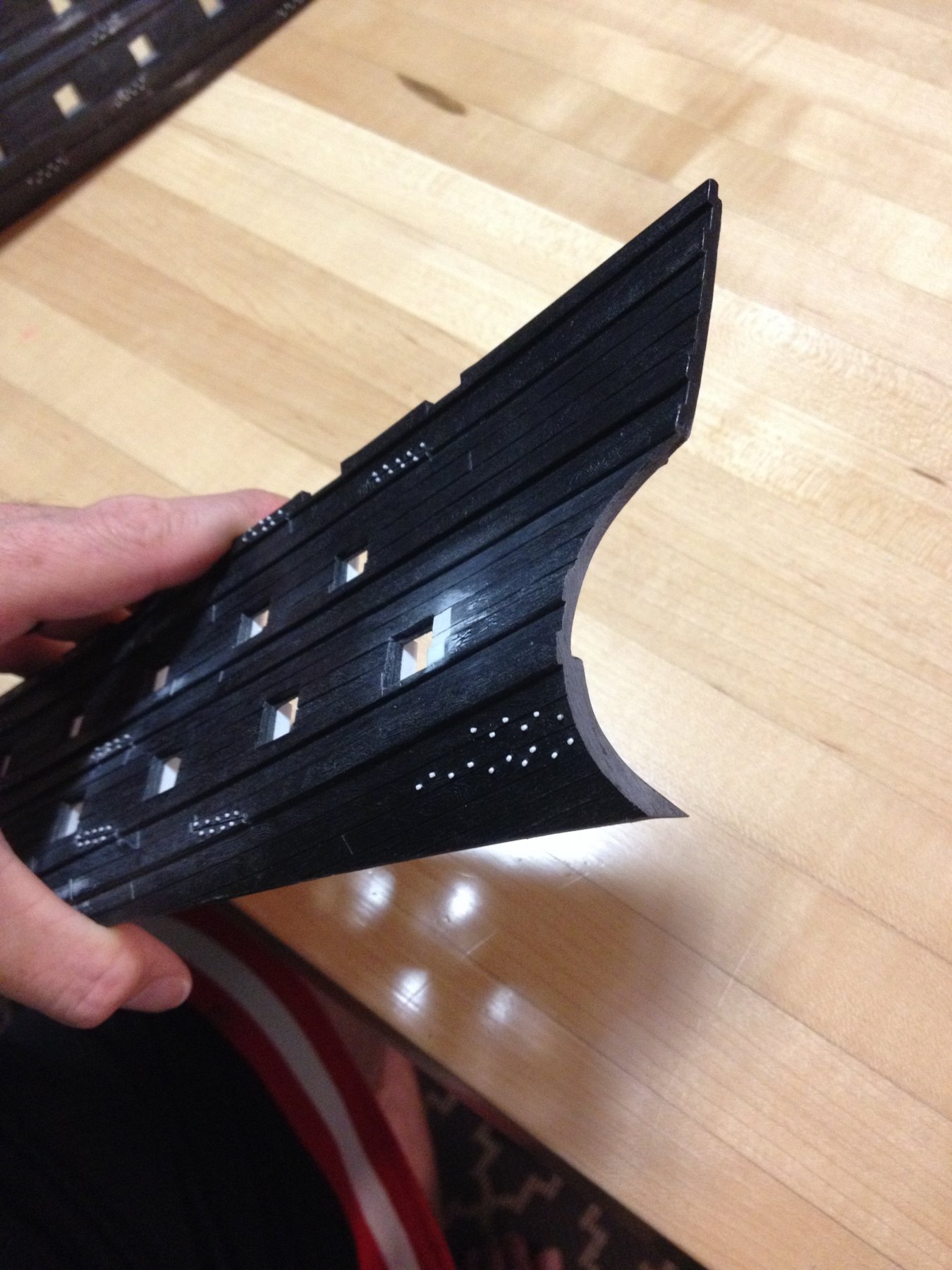
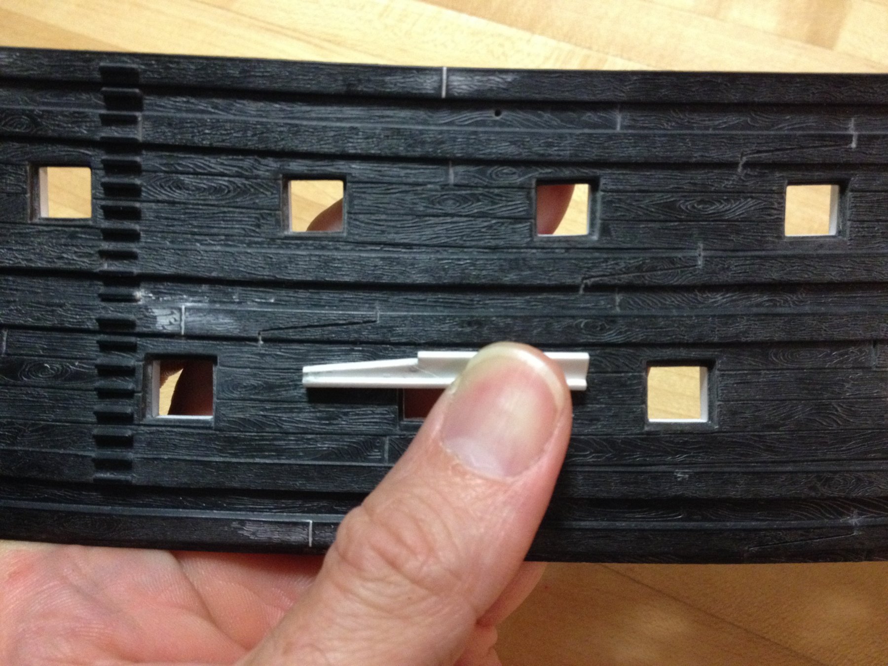
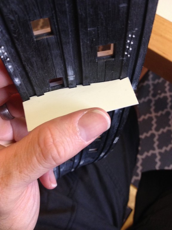
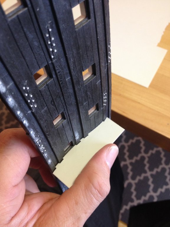
With the scarfs through-bolted, I decided to turn my attention to the skids of the waist - beginning by framing in the gangway steps. In my most recent drawing, I show the gangway steps moved one gunport aft because I thought it made for a more balanced appearance with the three skids forward of the ladder. I have decided, though, that this is an unnecessary modification because the spacing of skids, relative to the ladder, is often shown to be irregular in many of the VDV portraits I've seen. Added to that fact is the strong possibility that moving the ladder aft may hinder my ideal placement of the main channel. so, recently I picked up one of these scribe guages for exactly this sort of patterning application: it only seems to work well, if you push the guage square into the hull - as though parallell with the imaginary vertical plane, running down the center line of the ship. Then, I simply transfer the shape of the tumblehome and the wale locations to a sheet of .020 sheet styrene, which is thin enough to cut with scissors. I refine the shape with sandpaper around a large dowel and needle files for the areas that saddle a wale, until the pattern fits snuggly: Then, I tried the pattern in the forward edge of the ladder on the same side, as well as the fore and aft locations on the starboard side. I can see that with small, additional adjustments, this one pattern will suffice for all of the ladder framing skids. I then transferred the pattern three more times to the .020 styrene sheet, and then cleaned and refined to my scribe lines: The next step will be to use that same guage profile to establish the outside curve and depth of each skid, which will be slightly oversize and transfered lightly to each of these .020 patterns. I will then laminate these thin patterns to sections of .032 styrene sheet to make up the desired thickness of each skid member. I can then waste away most of the excess with sheet metal snips and get close to my lines with the Dremmel before refining and hand-fitting each skid in place. the ladder rungs, themselves have rounded ends, which I will cut square, in order to make a good joint with each vertical framing member. I will repeat this process for each different skid location moving forward. I should also mention that each of these skids extends into the upper bulwarks. I've decided to construct them in a lower and upper section that will be faired together, later on, in the construction process. The reason for this is that I want a solid plastic to plastic bond before painting of the lower hull. It will be a relatively simple thing to line up and glue in the skid extensions to the upper bulwarks.

- 2,699 replies
-
- 6
-
-
- heller
- soleil royal
- (and 9 more)
-
I suppose they did this to de-clutter the page. I'm not a fan of the change, though. While it's true that you can still see your likes and from whom, it isn't always clear what a person is "liking." You can extrapolate that they are responding to your recent posts, but they may be responding to any given post throughout the thread. What I liked about the old format was that, even if someone wasn't commenting, you could see at a glance who else was viewing the thread.
- 608 replies
-
- 3
-
-
- la couronne
- corel
- (and 1 more)
-
I've just been experimenting with Dan's suggestion for the through bolting, and it really works like a charm! There is no excess glue and you can emmory board them to height immediately. Huge time saver and now the carriage tackles seem like an actually pleasant job. Thanks again, Dan!
- 2,699 replies
-
- 2
-
-
- heller
- soleil royal
- (and 9 more)
-
I appreciate that, Dan! The scarfs are a small thing, but a vast improvement to the impression the model makes. I really like your idea for simplifying the bolting. The Dremmel Micro is light enough that I should be able to control the drill bit, but again, I can experiment on my scrapped lower hull halves. Also, your idea about the mechanical pencil, I think, is the way to go. I imagine I would pencil in the treenails after the main colors go down, but before the wash coat for light distressing. I think I would then need to spray some form of clear matte coating to seal them in, before going over that with a semi-opaque acrylic wash. I also appreciate the digital camera offer. I have a really good camera at home, but I often take my blog pics with the phone because then they are in the phone and I can create these posts, during my breaks, at work. For this and several other good reasons, the time has come, really, for me to upgrade my phone. There's also the single-handed ease of holding the phone and positioning the model in better light with the other hand. What I could also stand to upgrade is the overhead lighting in my kitchen 😉
- 2,699 replies
-
- 2
-
-
- heller
- soleil royal
- (and 9 more)
-
The other thing I need to do, at this early stage, is re-shape the lower transom, in order to incorporate the round-up of the stern. I apologize for the lack of in-process photos that would paint a clearer picture of what I'm actually doing. My Iphone 4 😔 runs out of storage quickly, so I sometimes have to choose between clearing the phone or making progress on the model. Anyway, what you are seeing here is the profile of the lower transom which has been reduced, inboard, by a heavy 1/16" and faired into the arc of the stern counter, so that it is now flush with the kit's glue surface support for the transom piece. As I get closer to mounting the hull halves to their new styrene base, I will shave away this old mounting surface and recess the new one by the thickness of my transom planking. Also visible, here, are the through bolts for the transom supporting knees (not sure what the propper name is for these interior timbers), which will eventually be scraped away, in part, where they interfere with the lower finishing; that is to say - not much. My process for the through-bolting is something I learned from Herbert Thomesan. All I do is take a single-edge razor to .020 styrene rod and - as square as my eye can tell - I shave off a hundred, or so, slivers that are not much bigger or smaller than 1/32". I, then, sharpen the tip of a toothpick with which I can set a small dot of Testors liquid adhesive directly to the hull. Then, with the very point of the Exacto, I pick up a reasonably square-cut looking sliver, on it's end, and place it onto the glue dot. Hold for five seconds, and then repeat. Despite wearing glasses, my eyes are still good enough for this close work, but I am meaning to purchase the type of magnifying LED visor that Dan Pariser showed me, recently. It takes a little practice, but once you have the hang of it, this moves along at a pretty good clip. At pace, I can do just under half a hull half in a session before I get too tired to continue. After I finish bolting the starboard wales, I'll take a little break from that particular tedium, and I'll pattern skids for the waist. Then I'll move on to the anchor sweep planking at the bows, scribing in the "hunting port," and making the lower and middle deck scuppers. After that I'll tackle the truly tedious task of washer/through-bolting all the carriage tackles at each gun port. And after that - I will move onto some form of simulated tree-nailing; I'm thinking the blunted tip of a pin, slightly heated, in a pin-vise. Here, it is usefull to have saved the lower hulls for conducting my experiments.


- 2,699 replies
-
- 4
-
-
- heller
- soleil royal
- (and 9 more)
-
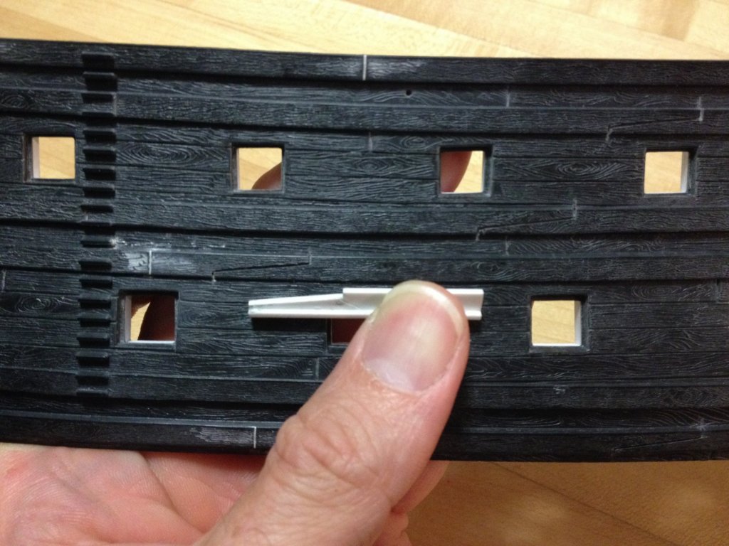
In order to cut in the forward half of the new port, I first layed out both the inner lip and the cut-back edge of the "planking" with a sharp pencil. Once I liked the looks of that, and could see that it was a level continuation of the port, I then scribed in those lines with the Exacto. Next, I took my new Dremmel Micro with a narrow, diamond crusted shaft, and wasted away everything within the inner lip lines. With needle files, I was then able to define the inner corners and fair to the scribe lines. Next, I fitted the micro with a straight-sided cutting bit that has no tooth on the bottom surface. I used this bit to cut the planking back from the lip until I was approximately close to my line and as far as the bit would allow into the corners. I now had a very roughly thicknessed lip in the black plastic of the kit. To clean up and define these edges, I used an 1/8" woodworking chisel for the corners and to scrape back the lip to a matching thickness, as well as a 1/4" chisel to trim the planking to my lines, making light passes and using a gentle wriggling motion. Despite my care in doing these things, there were two small mishaps. First, while using the straight cutting bit to rough back the planking, I dug too deep, the bit then grabbed and jumped out of the cut. In the process, I nicked a decent chunk out of my new, aft port stile. No problem: a touch of Squadron and the emmory board, and it was good as new. I have noticed this tendency of Dremmel bits to grab and jump, in wood, if the speed and depth of cut are off, but I wasn't expecting that in plastic. Lesson learned. Then with the 1/4" chisel, I pushed too hard, at one point, and sheered off the top lip of one port frame. No problem: I cut a small strip of sheet styrene, of the appropriate thickness and glued it in place. Once it is painted, one will never know the difference. The ease of repairs is what I like about plastic. Those same mistakes, in wood, would be much more labor intensive to repair because you can't hide the repair under putty and paint. To a large degree, in small scales, wood really determines your choice of tools and methods, so that you run the least risk of these mistakes. To finish off the interior framing, it was necessary to extend the sill, with a simple angled scarf joint, and then fit and glue in a new forward stile.
- 2,699 replies
-
- 2
-
-
- heller
- soleil royal
- (and 9 more)
-
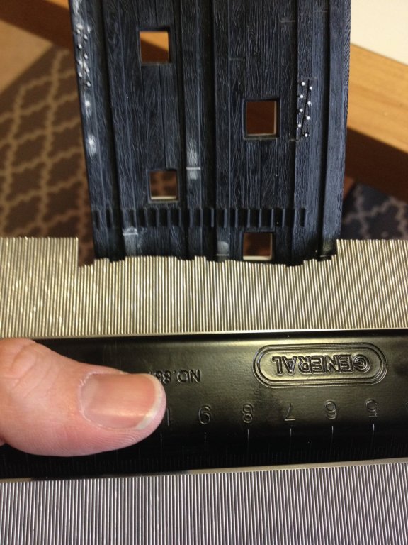
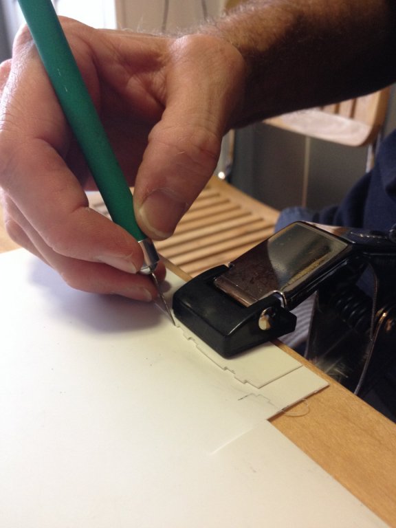
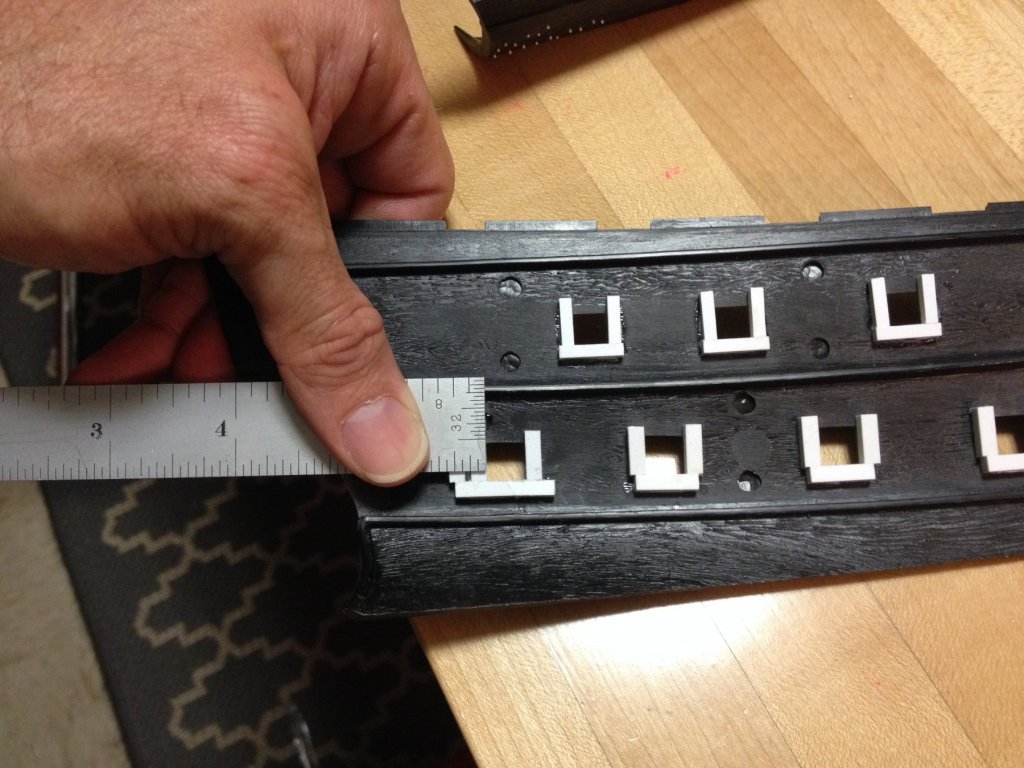
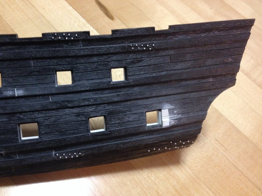
So, as I mentioned in the prior post, my drawing process has stalled, and I don't have any good answers as to why, right now, so I've decided to go ahead and begin detailing the lower hull halves. I will shift my focus back to the drawing, at some point, because I really need a good scale drawing for all of the ornamental work of the stern. For now, though, the change of pace is welcome. The first thing I wanted to do was to fill in all the butt joints on the wales and the eyelet holes for the chain plates because butt joints would never have sufficed for that application and I'm lowering the channels to the wale strake where these holes currently exist. I'm using Squadron white putty. Shrinkage seems minimal, it sets and hardens fairly quickly and it works easily with sandpaper, emmory board, or a knife. For this particular application, though, I have found that maroon abrasive pads do an excellent job of levelling the putty, without completely erasing the moulded, raised grain effect that the putty inevitably covers, upon application. The grain softens a bit, compared with un-abraded surfaces, but it should still show through the paint without the difference seeming jarring. If I think it all appears too patchy, under primer, then I'll soften the rest of the grain later. Here, you can see a few examples of the filled and leveled butt joints, as well as the simple, reversable jig I made to mark out scribe lines for my new scarf joints. To cut them, I lightly drag the tip of an Exacto blade (#11 works) backwards, and against the pattern a few times. Once a faint line is apparent, I use increasing pressure on the backward stroke to engrave the plastic to the width of the blade. I found it helpfull to establish the vertical stop cuts, first, and then to drag the knife from the stopcut, towards center of the scarf, in each direction. Once I had a rhythm going, it moved fairly quickly; I averaged one half of a hull half in a session. The next challenge was a little daunting, at first. I wanted to move the aft-most gun port of the lower battery forward by 3/16", in order to allow a clear space for the full lower finishing of the quarter gallery. To begin, I inserted a new framing member (1/8x1/8" styrene, mostly obscured by the steel ruler) on the inside face, and 3/16" forward of the aft port stile. Note: this is an after the process photo, which also shows the re-located forward port stile; in reality, though, this second new stile doesn't come until later. So, with a new ledge, onto which I can now glue small fitted pieces of sheet styrene, I began to fill-in the aft 3/16", on the outside face of the port. The first layer of sheet styrene was the same thickness as the interior lip of the stock gun port. This, I glued flush with the edge of the new aft framing member. The second layer of sheet styrene was very nearly the thickness of the kit "planking." The difference was less than a 1/64", which was easily filled with Squadron white, and leveled with a coarse emmory board (which provides some grain texturing) and a knife. Also at this time, and before applying putty, I built out the missing bit of aft wale section with strip styrene. I then scribed back-in the missing plank lines: On break, I'll continue this post to describe the cutting in and framing of the forward half of the new port, as well as the through-bolting of the wales and the transom knees.
- 2,699 replies
-
- 6
-
-
- heller
- soleil royal
- (and 9 more)
-
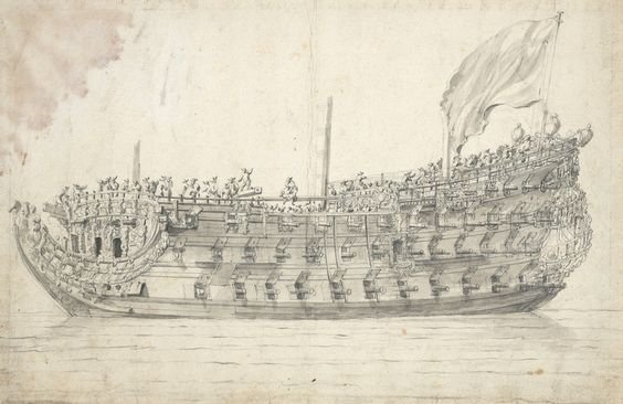
Hi Doris, Yesterday, I was surfing through Pinterest, as I often do, when I found this image of a VDV ship portrait. It was not specifically identified as the RK, but it certainly seems to be her. If you haven't seen this, I thought you might appreciate the wealth of detail that is apparent, here:
- 1,035 replies
-
- 10
-
-
- royal katherine
- ship of the line
- (and 1 more)
-
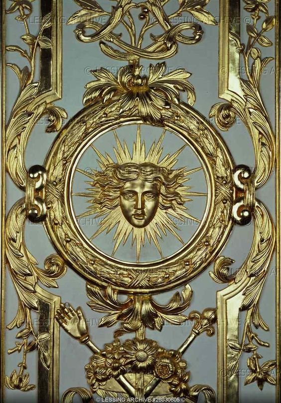
A separate artistic choice I am considering is painting the exposed limbs, faces and hair of the Asia, Europe, America and Africa figures semi-gloss or matte black and their costumes in gilt. Again, the black helps to break up the gilt and give definition to their individual costumes and head dresses. Just a thought.
-
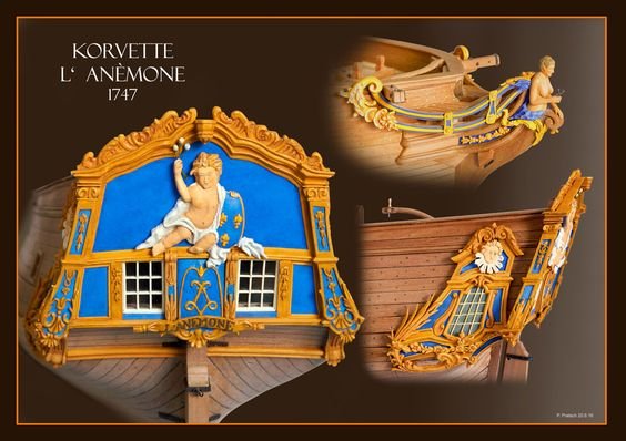
I was surprised at how little I was able to find out about period paint color and it's usage. In the end, there seems to be enough credible period portraiture of the ship to suggest that full ultra-marine was a plausible possibility. I'm thinking, in particular, of the lludolf Bakhuizen portrait of her at the Battle of Barfleur. In the end though, a ship like SR1, because of its uncertainties, leaves open a certain amount of lattitude for making artistic choices. Yellow ochre was certainly in use among the Dutch and English, during this time period, so it is reasonable to suppose that the French adopted the same practice. Personally, I think that gilding loses its visual impact when everyhing is covered in gilt. I think that ochre and gold can work to accentuate each other, and the ochre will also show the weather washes nicely, in the creases and crevices. The other thing I like about that corvette model I posted are the white window frames. They pop really nicely on that model.
-
I haven't made my mind up about this completely yet, but at first I was liking this muted grayish blue from Versailles, as the primary blue, with ultramarine accents on select areas of the stern quarters and tafferal: I think the gilt work shows up really nicely against this color. But, then, I saw this model and it got me to thinking about the way this brighter, light blue plays against the yellow ochre: I really like this as a primary combination, where most of the panel framing would be in this yellow ochre, while reserving the gilt work for the large and important figurative carvings and certain essential accent carvings, i.e. anything that directly references the sun, or the Sun King, himself. In this scheme, I would still use Ultramarine blue as a secondary, accent color. This second approach may or may not be accurately reflective of what was being done at the time, but artistically, I just like it.

-
The question of what shade of blue would be appropriate is a difficult one to answer. The deep, ultramarine blue which was made from pulverized lapis, would have been exhorbitantly expensive to make, and so in my opinion - I believe it would have been present on SR, but used selectively, as an accent color. Most of the upper bulwarks, I believe would he a lighter shade of blue. Given SR's special status within the fleet, however, it is possible that they spared no expense and did her whole upper works in ultra-marine blue. In the absence of more in-depth research, I don't think there is a completely right or wrong answer. For guidance, though, one can look to the restored interiors of Versailles, which presumably, would be painted in shades that mimic period colours. The most I could determine, so far, was that other shades of blue could be more cheaply produced from oxides of copper. Later, when I get home, I'll post a pic of a colour scheme that I personally like and plan to use.
-
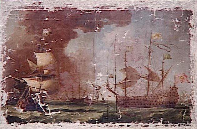
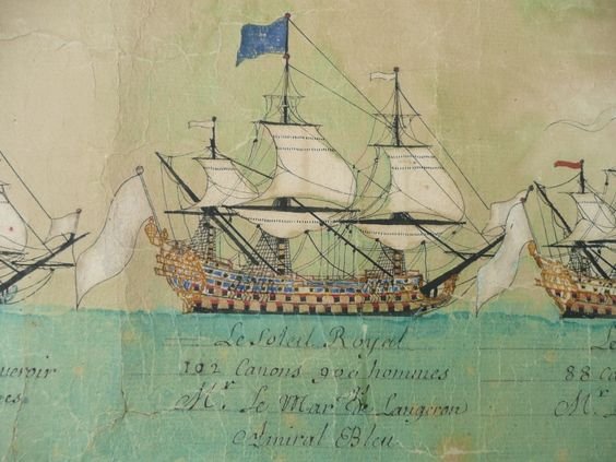
So, here are another two interesting little bits of ephemera that I found on the same site that Michel Saunier primarily posts his build-log for SR: I have no idea, what this top image actually represents: whom the artist was that created it, whether this badly degraded print is some kind of postcard of a larger, original work, or of course, what ship is actually represented here. It does appear to be a French ship. It is pierced for sixteen ports on the first battery. It does not seem to correspond with La Reyne, as there do seem to be three tiers of stern windows. Interestingly, this is one of only a very few images of early French ships that show any substantial raking of the main mast. Could this be Soleil Royal, numero uno, at some point before her demise in 1692? Can anyone shed light on what this image is in reference to? The second image is a line of battle schematic of the French ships involved in the Battle of Malaga, in 1704. The SR pictured, as I understand it, is the ex Foudroyant of 1693. This is not terribly useful, for my purposes, although it is interesting to note the blue upper bulwarks and the stern galleries on the main and quarter deck levels, only - perhaps in emulation of the post-refit SR of 1689? Admittedly, that is all a stretch of plausibility! --- In actual build work, the project is moving along nicely. Wale scarfs are scribed, scarf bolting is under way, as is re-location of the aft most port of the first battery, which I am moving forward 3/16" in order to make a little extra room for the lower finishing. So far, I've successfully closed in the aft portion of each port with sheet and strip styrene, and now I need to carve in the new forward half of the port into the kit styrene. It has been interesting to me how the old plastic sands and scrapes; although it still seems plenty flexible, it is quite hard and sort of thready when you sand or scrape it. I don't remember that being the case with the first SR I built, but that was a later pressing from the 80's, under the IMAI brand. I'll post a few pictures in the near future, perhaps after I've gotten those two ports moved and fully reconstructed, and after I've re-shaped the lower transom profile, in order to accommodate the new round-up of the stern.
- 2,699 replies
-
- 5
-
-
- heller
- soleil royal
- (and 9 more)
-
I am 100% in agreement; we have to find which methods work for us, that give us good results wihout too much headache. If it isn't fun, then why bother, right?
- 2,699 replies
-
- 3
-
-
- heller
- soleil royal
- (and 9 more)
-
Hello hjx, Thank you for taking the time to visit my build log. Your kind words are greatly appreciated. To my mind, and spanning roughly 100 years from the 1660s, onward, the French were responsible for creating the most artistically interesting ships, and then as ship design moved into the next epoch, and ships became flatter, the French were responsible for creating some of the most widely emulated naval architecture of any of the great sea-faring nations. As you can attest with your own projects, hjx, the French are an almost limitless source of compelling subjects. Now that I have returned to the hobby after a pretty long hiatus, it is really fascinating to me how modelers have adapted technology to make better models. You, for example hjx, are using Zbrush (full disclosure: I'ma have to look that up) to create 3D models that can be refined within the software and then fed to a CNC machine. The roughed blank is, artisitically, a much better starting point than most of us would be able to achieve if we had to do all of that wasting by hand. But what was really interesting about your figurehead, hjx, was that your manipulation of the 3D model seemed to make her appear like a more youthfull version of herself; if only plastic surgery could have this do-it-yourself-at-home user friendliness! Anyway, I will continue to watch what you are doing with great interest, as there is much for me to learn there.
- 2,699 replies
-
- 2
-
-
- heller
- soleil royal
- (and 9 more)
-
Hi! I am completely fascinated by what you are doing here, and will be following along with great interest. In my opinion, the face of your figurehead - even in its rough, un-pollished state - is an improvement over the original.
-
Well, Mark, I wonder the same thing, and despite my experiment in deleting path objects (and even saving the revised copy of the document after deleting, which didn't seem to help) I suspect that this very issue is the crux of the problem. By the time I finished with the frieze and started the quarter galleries, I had already noticed a bit of a delay in processing, but it was not at all severe. But then, very abruptly, functionality just seemed to shut down completely. I like your idea for a work-around, Mark. If that solves the problem, I will make it work. Ideally, I would like to publish a complete drawing for the project, but really for the purposes of this build, I really only needed an accurate layout for the frieze (which I have) the QG (30% complete) the stern and bow angels (got them - made them less haggard looking, BTW). I will keep at it, though, and see if I can correct my mistakes. Thank you for weighing-in, Mark!
- 2,699 replies
-
- 2
-
-
- heller
- soleil royal
- (and 9 more)
-
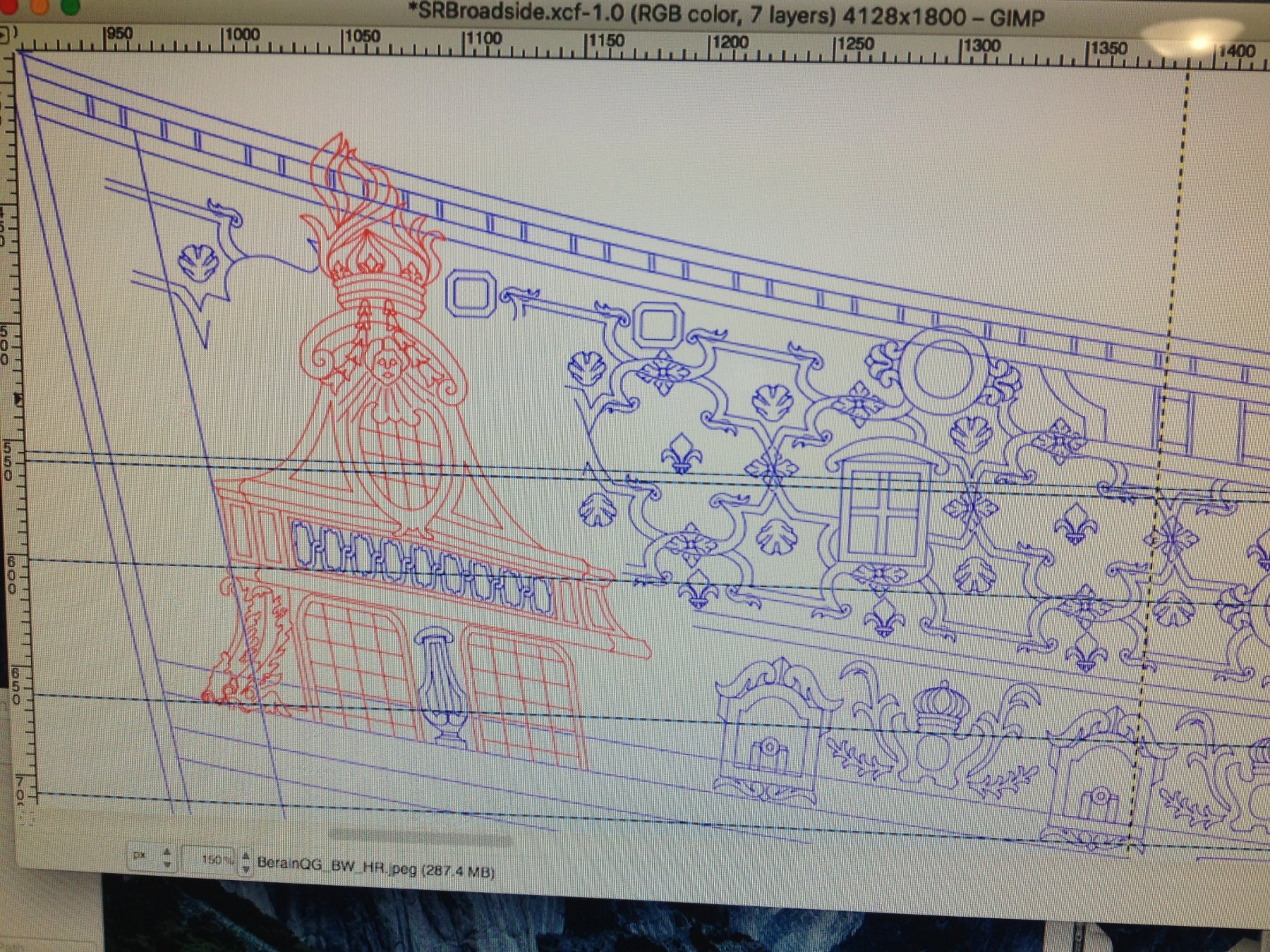
Increasing the work space didn't help either. It dawns on me, just now though, that maybe I need to decrease the workspace so that my scanned JPEG pops up more closely to 1:1 scale. As I recall, when I first created this document, one of the first things GIMP wants you to do is establish the size parameters of your workspace. Not knowing any better, I picked a rather arbitrary size that, on the ruler scale, was bigger than the paper my original drawing was on, and then I imported the scanned image as a JPEG into it's own layer. Maybe I just made the workspace too big, in the first place, and that is now compressing my image into too small an area. I'll do another experiment to see if that helps any. Of course, I am open to all suggestions from the more computer saavy contingent, out there. Although, I'm sure I have done several things wrong to Eff this thing up, I believe (hope) what I've done so far is salvagable. I really don't want to start the whole drawing over again in a different software package. I've seen modelers like NekO use GIMP to draft their plans successfully, so I know it is possible. In the meantime, though, I have begun detailing the lower hull halves so that the project is at least moving forward. At the moment, I'm scribing scarf joints, at appropriate intervals, into the wales and am pleased with my engraving, so far. I'll putty-in the original moulded butt-joints. Then, I'll proceed with the myriad other detail additions: carriage tackle through-bolts, the anchor sweep timbers at the bow, simulated treenails, skids, scuppers, etc. I'll post some pics when there's some substantial progress to see.
- 2,699 replies
-
- 2
-
-
- heller
- soleil royal
- (and 9 more)
-
I tried a number of experiments to see whether I could identify the problem. First, I closed my working document and opened a new, blank workspace in GIMP. My thought was to see whether it was a problem within the document I created, or a computing problem with my relatively old MAC from 2007. Although I'm running the current operating system, and I've maximized the machine's RAM, I thought that perhaps the computer was struggling, now, to complete this exercise of connect the dots. In the new document, however, I was able to easily create nodes with extracted handles, and I was able to move them and manipulate their curves instantly. Stroking paths was also instantaneous. So, it would seem, the computer isn't the issue. Next, I made a separate copy of my master document, and I went in and deleted all un-necessary paths that weren't directly connected to, or adjacent to the quarter gallery path object; so, the upper bulwark frieze, the gunports, the sheer railing, the acanthus escutcheons, the filligree between the knees of the head - all of these path objects, I'm calling them, containing many thousands (at this point) of nodes were deleted. The thought, here, was that perhaps the program becomes sluggish when you add too many nodes, as this use of the program (line drawing using the Bezier path tool) is not the primary intended use of the software. Photo manipulation is what GIMP was primarily designed to do. I was sure that deleting all extraneous paths - even if it meant creating multiple isolated documents, representing various areas of the design (quarter gallery, stern, bukwark frieze, etc), would restore the utility of the Bezier path tool. It did not. Still 4-5 second lag times. Finally, I thought that increasing the size of my workspace and the layer images might provide a bigger, more manageable area for these many thousands of nodes to reside in. As it stands, when I open my drawing, what appears is a very small (about 1/4 the intended scale) image of my drawing, which I then zoom-in on to work at. I have found that a 78.5% zoom provides the exact 1:1 scale that I need for my drawing. When I post images of my drawing, this is what you are looking at - a 78.5% zoom. .. Break over - will post this and more to follow.
- 2,699 replies
-
- 2
-
-
- heller
- soleil royal
- (and 9 more)
-
Hey Dan, Your illustration of the paralax issue is made quite well, with these examples from the Sussex build, and the point you are making is well received. With regard to the black and white Berain drawing that I am using as the basis for my quarters and the bulwark frieze, it is difficult to say how literally one should take the drawing because there are a number of similar perspective issues that seem a little screwy; was this drawing a proposal for the ornamentation, or a portrait of the actual ship? No one seems to have an answer to that. Personally, I suspect that it is a proposal drawing and that the ship, as actually fitted out, probably differed according to the practicalities of applying ornament to the necessary architecture of the ship. We'll never know, unfortunately. As a general rule of thumb, though, I agree that the model builder should err on the side of designing a plan with complete port frames, as an example. Progress on my drawing has stalled, for the time being. I was making great progress with the quarter gallery drawing, but as I got to the two pair of dolphins that flank the two main deck windows, my ability to add nodes, to move them around and manipulate curves with the bezier handles slowed down dramatically. Suddenly, I could no longer create a node with handles already extruded, by simply click/hold/dragging the cursor, as before. Now, new nodes were just simple nodes without handles. The only way I could extract handles was to pull on the line between nodes, and even then nothing happened without click/drag/holding the cursor for four to five seconds. If I want to move a node - same thing: 4-5 seconds. Obviously, that makes the process of drawing anything incredibly cumbersome. ... I'll finish this post on my break, but I'll post this much now so I don't lose it.

- 2,699 replies
-
- 3
-
-
- heller
- soleil royal
- (and 9 more)
-
As expected, with Jan being the English equivalent of John. 'Never hurts to ask, though. Cheers! - Marc
- 487 replies
-
- 3
-
-
- ship of the line
- 80 guns
- (and 1 more)