


Tecko
-
Posts
262 -
Joined
-
Last visited
Content Type
Profiles
Forums
Gallery
Events
Posts posted by Tecko
-
-
1 hour ago, DORIS said:
...
I have not been here for a longer time, I have harder days in my life now, but ships and making their models help me to overcome it....
Sorry to read this, Doris. I am in similar situation. Hoping better days will become the normal for you.
-
Hello CapnMac82.
Have been very busy lately, when I am not too ill to do so. It seems to be all or nothing at this stage of life. Time is running out. Had to temporarily cut out FSM and others. Decided to just focus on the better forums, such as this one.
Thank you Mac for your kind and encouraging words.
- Baker, paulsutcliffe, BANYAN and 1 other
-
 4
4
-
9 minutes ago, mtaylor said:
It happens to the best of engineers, Peter. I saw it too often when I worked in engineering decades ago before moving to IT. Seems the brain focuses on one problem and doesn't see other problems it's creating. In some circles, they would say you dove down the rabbit hole. Been down it more than a few times myself. I hope that going "global" for a bit will clear things up and you find you're not far off.
Thanks. Sure hope so.
-
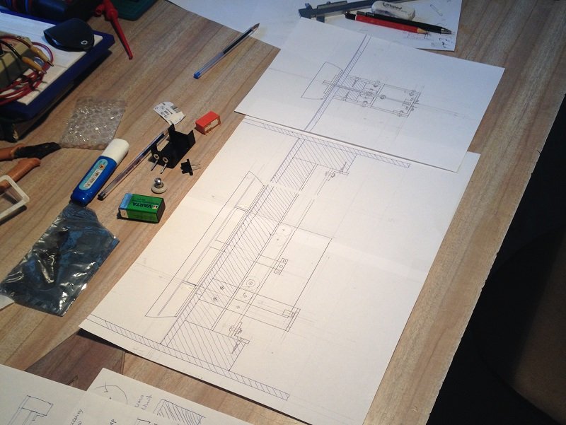
HEADACHE DAY today. Came to a full stop with controlling the boat motor. Could not remember what my operating plans were for it. Discovered many unresolved issues with the design. Decided to start from scratch, in regards to operating the console. There are about 14 steps to complete. Got stuck in step 3 already. It turns out that there is a need for major re-design.
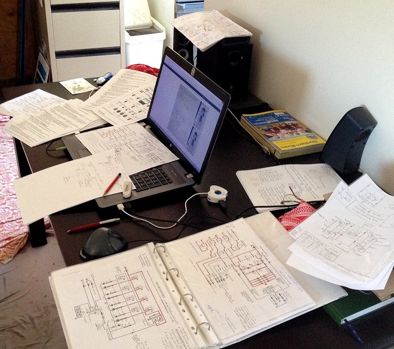
Starting operations manual from scratch.
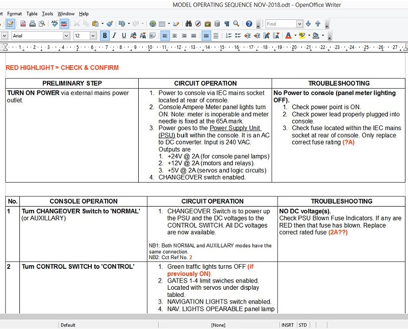
As you can see, much of the original plan needs to be altered, and this is just for selecting up and downstream travel. Strange how one can become blind to things when focusing on it for too long.
-
-
Thanks fellows.
______________
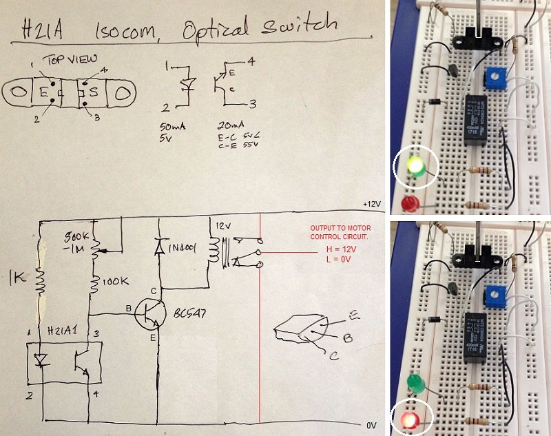
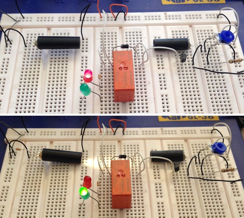
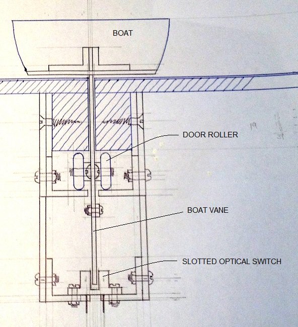
Created a similar circuit for the optical switch which switches boat pulley motor OFF when it reaches end of travel. Top right image shows boat vane about to enter sensing gap of optical switch _ green LED indicates motor is ON. As soon as vane passes midway of optical switch, relay is tripped _ red LED indicates motor is OFF. Will create circuit board for two circuits, one for each end of transport track.
-
-
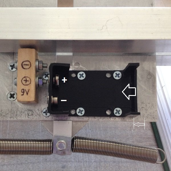
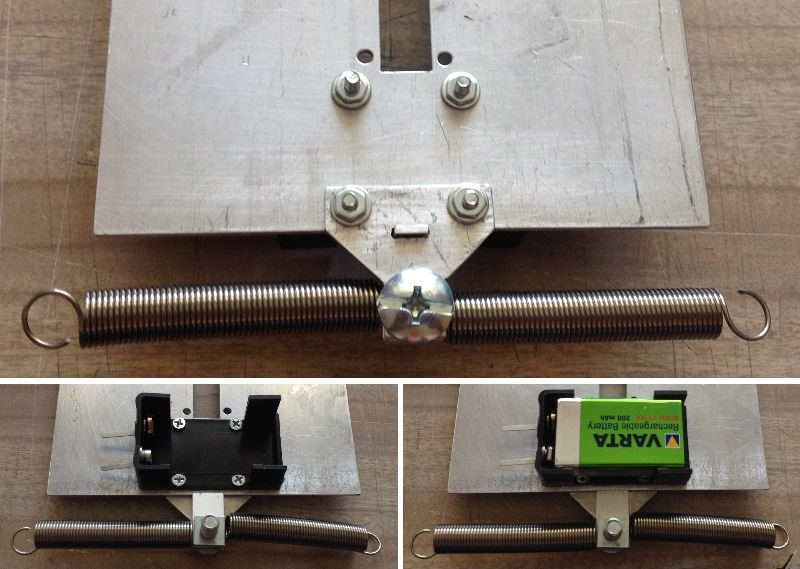
Had a boat vane problem. The battery holder got in the way of docking at the other side of the track. Had to relocate the battery holder, optical switch, and the limit microswitch, by a total of 11 mm. That is a lot!!! Had to move the battery holder 6 mm, and the optical switch 5 mm, to left.
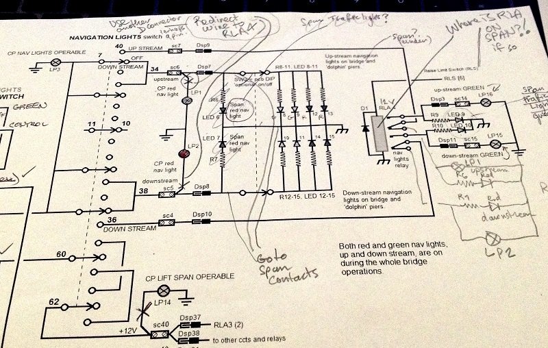
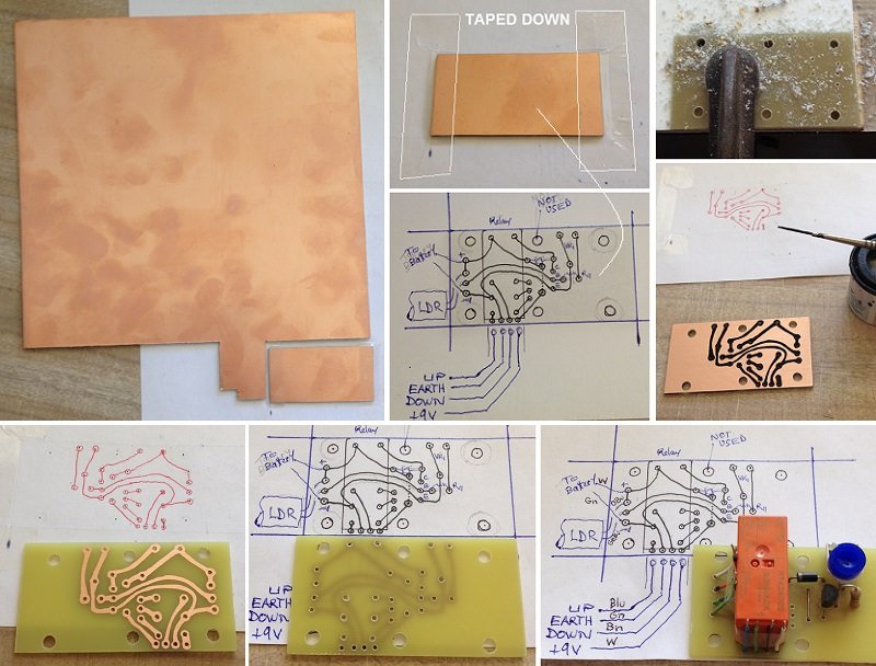
Designed the simple light detector circuit. The relay is dormant while light beam is OFF, allowing downstream nav lights to be ON, represented by the red LED. Once the light beam is ON, the relay becomes active, changing over nav lights for upstream, represented by the green LED.
- lmagna, hexnut, paulsutcliffe and 5 others
-
8
-
Thanks fellow modelers for your kind reactions. Much appreciated.
_____________________________
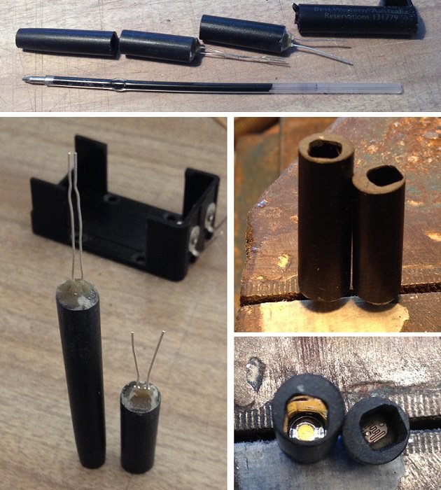
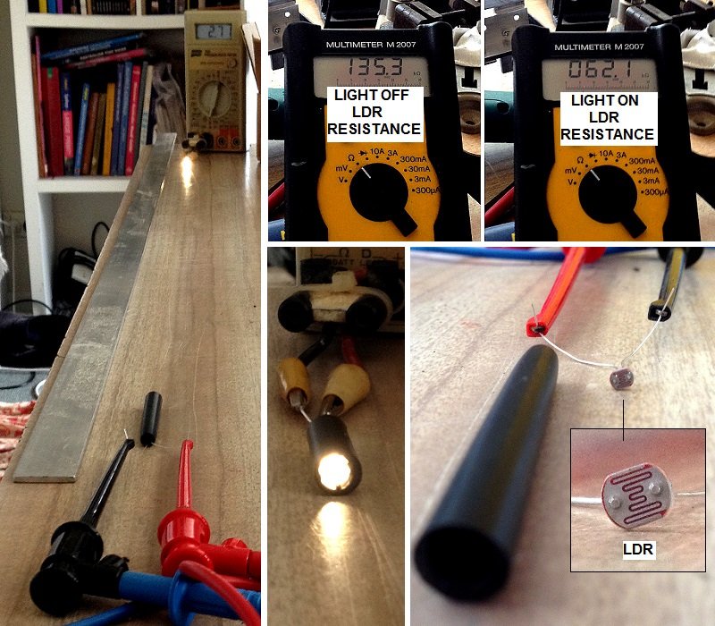
A favourite LED holder is a pen tube. However, this pen had a strange bore shape. Not only was it square, it was also way off centre. But I quickly put it to my advantage. Upon rotating the tube, one can shift both LED and LDR longitudinal axis to align better, to each other, over a long distance.
-
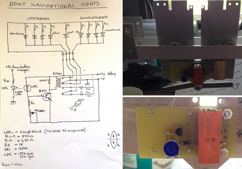
BOAT NAV LIGHTS CHANGEOVER TRIGGER
Had difficulty figuring how to switch the boats navigational lights from downstream to upstream travel. Mechanical switching proved troublesome to arranged when boat reverses direction. Decided to use an "old party trick" using a light beam to trigger a change in nav lights.The idea is that the LED light beam is ON whenever the pulley motor is in clockwise (CW) rotation (boat to travel upstream). This light is fixed at on one end of the tracks. On the boat vane is the light beam sensor, known as a Light Dependent Resistor (LDR). While the vane moves back and forth, the LDR is always facing the LED light source.
When the light is OFF, the LDR resistance becomes high (135,000 ohms). This keeps a transistor in OFF mode. When the pulley motor is switched to CW operation, the LED light turns ON, and shines on the LDR. Its resistance instantly drops to 62,000 ohms. This low resistance allows a transistor to be in ON mode, tripping a relay. The relay switches the boats nav lights over from downstream to upstream configuration.
Here, I am experimenting with the LDR.
-
8 minutes ago, mtaylor said:
I meant to ask earlier about the batteries. Are you building a charger into the system for the batteries? From past visits to museums, they don't seem to be up on doing maintenance like recharging batteries, etc.
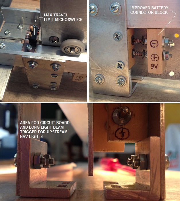
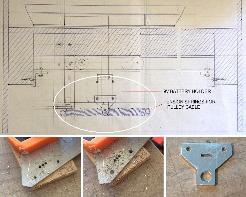
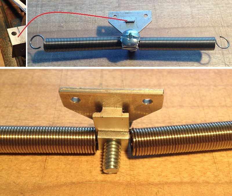
That is correct. The 9V rechargeable battery will be, inserted into its battery holder, attached to the boat vane. the holder will be wired to the connector block (see above). The spring loaded connections are stationary, and wired to a 9V battery charger. This charger will be housed under the display table within the control box. Only maintenance (hopefully) is to replace the battery now and again.
-
-
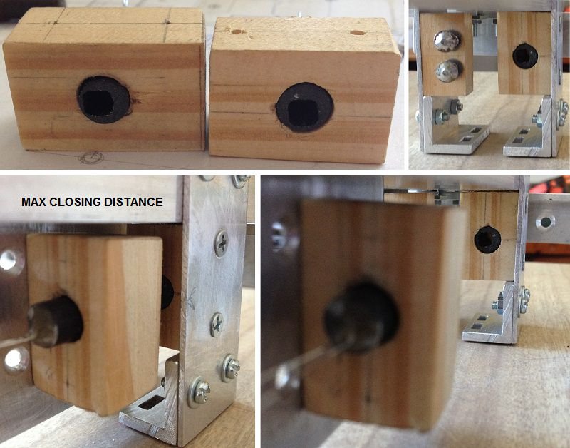
The boat has its own power source, a 9V rechargeable battery. However, it needs to be recharged. A docking connector has been made.
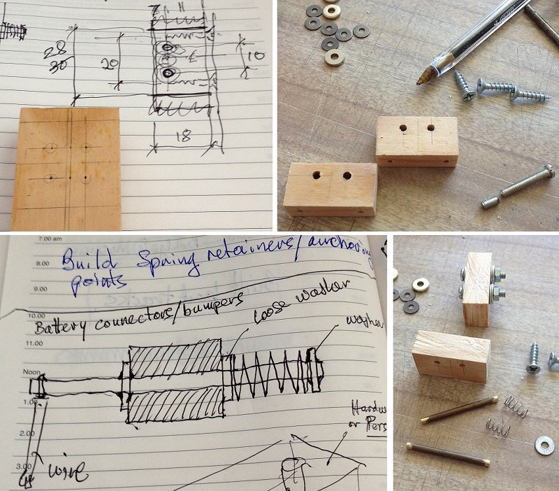
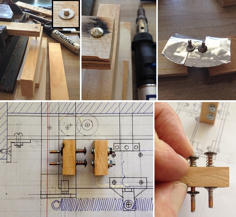
Upon assembly, I discovered that the connectors are misaligned. Will have to make a new wooden terminal block for the battery side of the connector. Will do this tomorrow.
-
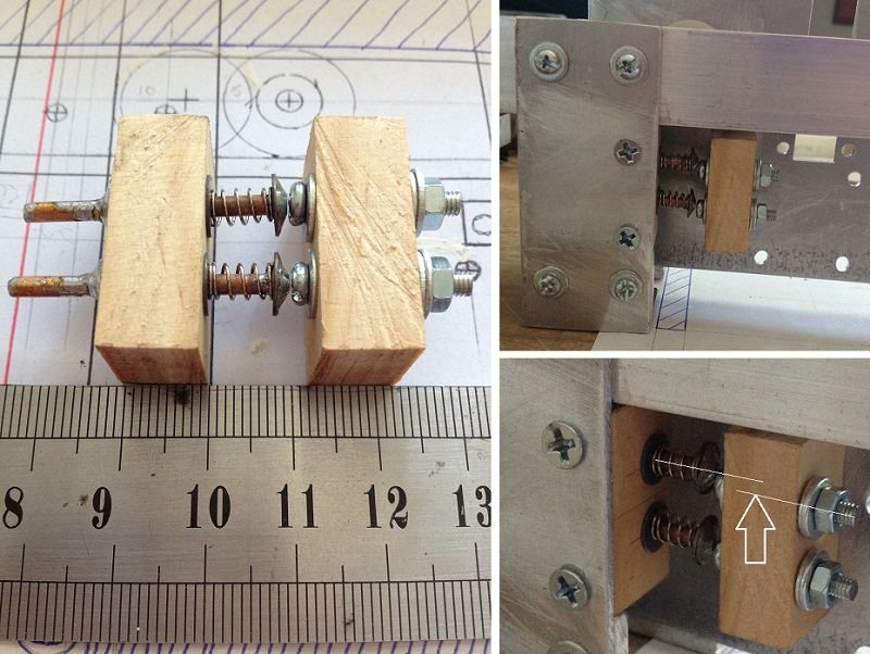
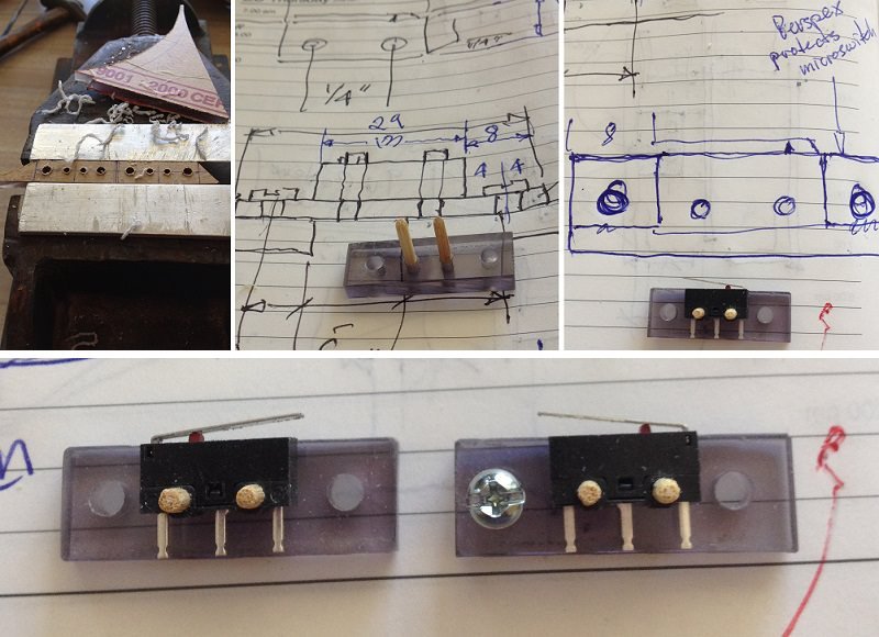
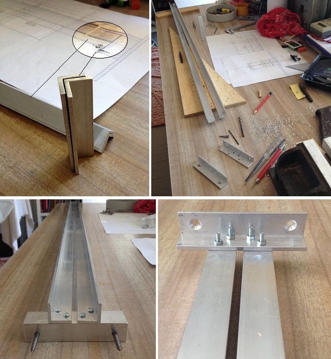
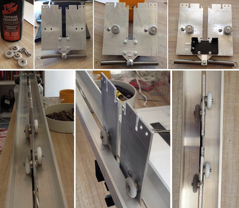
Nothing much to show. Today was mainly spending time on other volunteer work. However, was as able to figure out where and how to attach two microswitches to both ends of the transport frame. These are emergency limit switches, in case an optic switch fails. If this happens, the microswitch will switch motor power off, but the boat vane will hit the end of travel. The Perspex bracket will take up the brunt of the impact, and save the switch from being smashed. Besides, the springs will take up the 1/2 inch drift of the pulley cable.
-
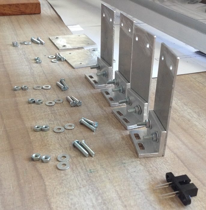
Trimmed quite a few bolts to minimize future hassles of restricted space problems.
Drilled two holes which used would have the bracket upside down. Added centre support bracket.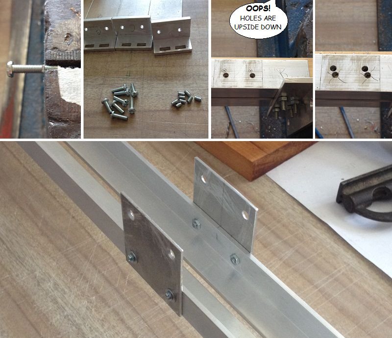
After assembling brackets, it was time to test to see if the vane will align in between the optical switch.
Though it looks all well and aligned, I may still incorporate a simple tin plate funnel, and file edges of vane to a bow point.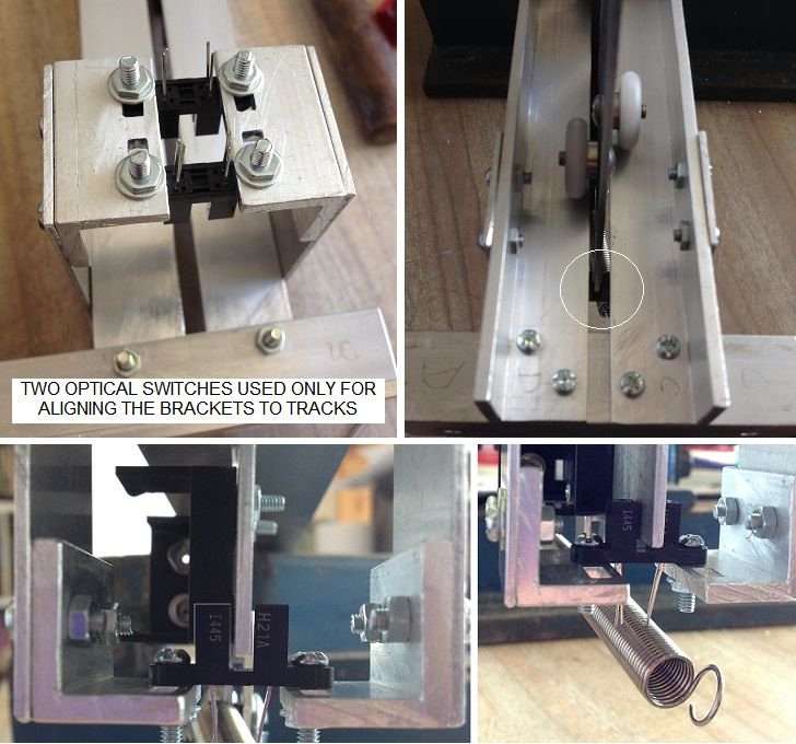
- Jack12477, mtaylor, paulsutcliffe and 2 others
-
5
-
1 hour ago, BANYAN said:
Hi Pete, you've made some progress since I saw your diorama. I like the engineering you are using and assume the light beam (optical switch) is a better option than a limit switch at each end?
Folks, having seen this diorama I can say that the actual construction looks even better to the eye than the photos show; a testament to Pete's artistic abilities.
cheers
Pat
Thanks Pat for complement. I take it that your trip was a success.
The optical switch is the first sensor. Because the pulley motor is not a stepping motor, there is a drift of the axle rotation on switch off. Meaning that the vane will continue traveling for about 1/2 inch. Also, the optical switch applies no resistive tension to the traveling vane. However, I will be using a microswitch (limit switch), placed near end of maximum travel, to ensure shutting off the motor; in case optical switch fails. This will be seen later in the present build.
-
-
-
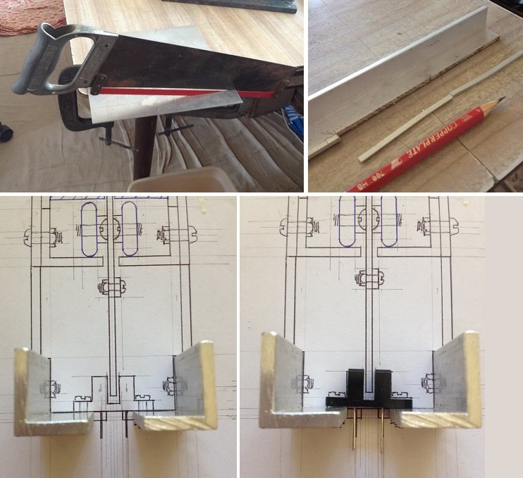
To stop the boat at either end of traveled distance, an optical-switch is being incorporated. The switch is triggered when the boat vane cuts the light beam between its 'U' structure. Two sets of brackets are needed for both ends. The switch needs to be positional to compensate for any vane drift after switch-off. In other words, I can position it to have the vane stop before crash into end of travel (slot in display table).
Changed design of track supports. It already is supported at both ends, so it does not need to be also screwed to slot braces (as in original drawings). Instead, another track support will be placed half way along the track. This will stiffen the track and eliminate any sagging.
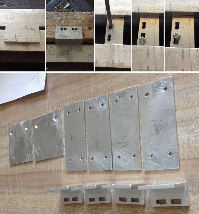
You will notice two slots per side bracket. Originally it was to be one long slot. I realized that the centre portion was not really required, so I left it in.
- Louie da fly, Jack12477, Bob Legge and 4 others
-
7
-
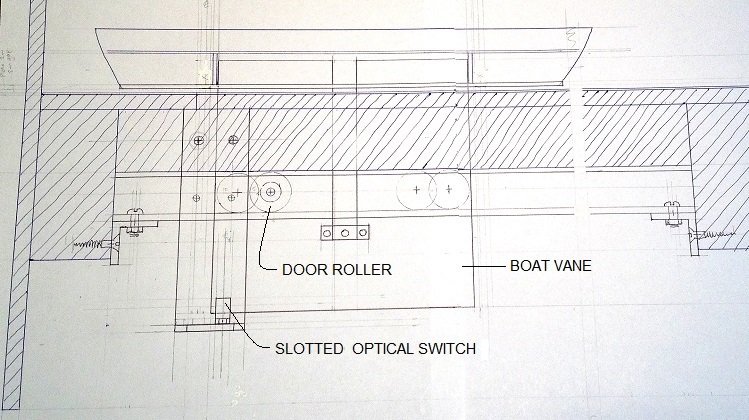
-
Figuring out the boat transport railing, under display table.
- BenF89, paulsutcliffe, G.L. and 2 others
-
5
-
Awesome build. The details are exceptional.
- popeye the sailor, mtaylor and BANYAN
-
3
-
38 minutes ago, BANYAN said:
Looks really good mate - love that small boat heading for the pier with the surprise in store for them (Kraackin)
")
I am driving up your way later this month; if you are not otherwise engaged would love to pop in an see this beauty?
cheers
Pat
Thanks Pat. I sent you a PM.
-

Wardell Bridge and boat by Tecko - 1:72 - diorama
in - Build logs for subjects built 1901 - Present Day
Posted
Sorry to read about your health issues and side effects, Mac. The road signs that lure us to pull over and distract/delay our purpose for the journey. I have two journeys to complete, one is to be creative for others, the other is to be closer to the truth. Illness brings me closer to the truth about life. Creativity is a way of expressing that life.
Thanks again Mac for sharing with me, and for your thoughtful blessing, my friend.