herask
-
Posts
218 -
Joined
-
Last visited
Content Type
Profiles
Forums
Gallery
Events
Everything posted by herask
-

Yet Another Pandora 3D build
herask replied to herask's topic in CAD and 3D Modelling/Drafting Plans with Software
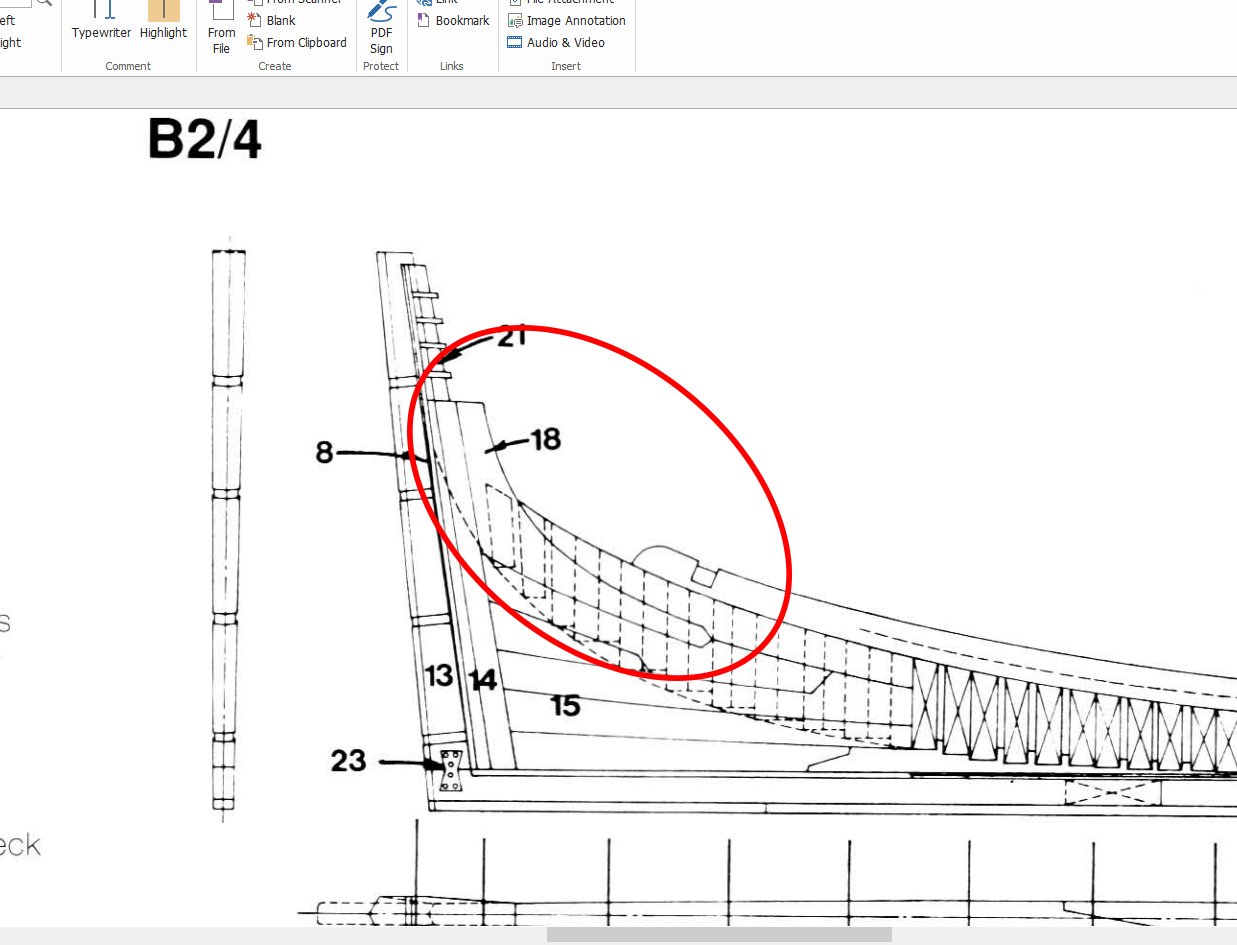
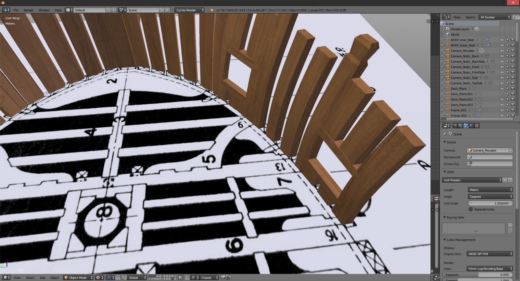
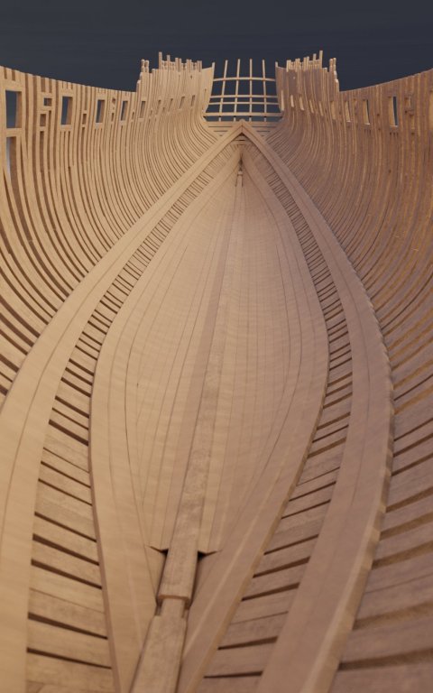
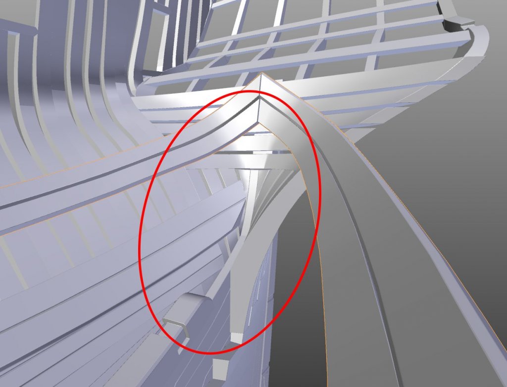
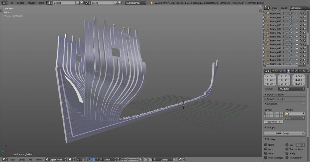
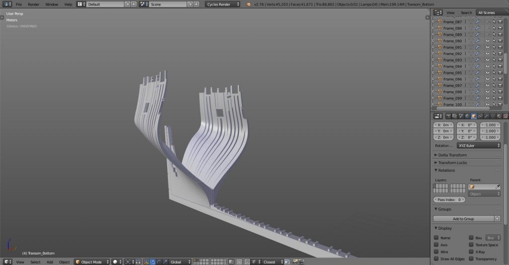
hm, I might have circled it wrong. I didn't mean the deadwood knee, that I have. the problem that bugs me is this: my transom frames (the vertical ones) sit flush with the deadwood knee fore edge, and there's nothing to receive the end butts of inner planks that connect at the middle at the deadwood (if that makes sense O.o). you can see on last images how my thick stuff connects to itself instead of some piece of wood or something in the middle, above the keelson. I made a mistake somewhere and don't know where, as I have followed plans that I have. that red circle on the deadwood drawing should show the empty space, like there should be continuation of the keelson toward the top of the deadwood knee... (again, I hope I'm making any sense here)... EDIT: um... is it called STERNSON maybe? EDIT 2: ah yes, it's there on one of the hold arrangement plans, the sternson knee. no clear drawing of it, I'll have to guess the shape. other builds will help though... -
vector programs like corel, illustrator and such have the tool to automatically convert bitmap image to vector shape. but as with any automated tool it's prone to errors. the cleaner the bitmap the better the result. for instance if you have nice sharp scan of plans with strong contrast between the lines and background it shouldn't be much of a trouble to convert to good vector shape. but almost always the result is not perfectly clean and manual adjustments are necessary... cheers Denis
-
Yet Another Pandora 3D build
herask replied to herask's topic in CAD and 3D Modelling/Drafting Plans with Software
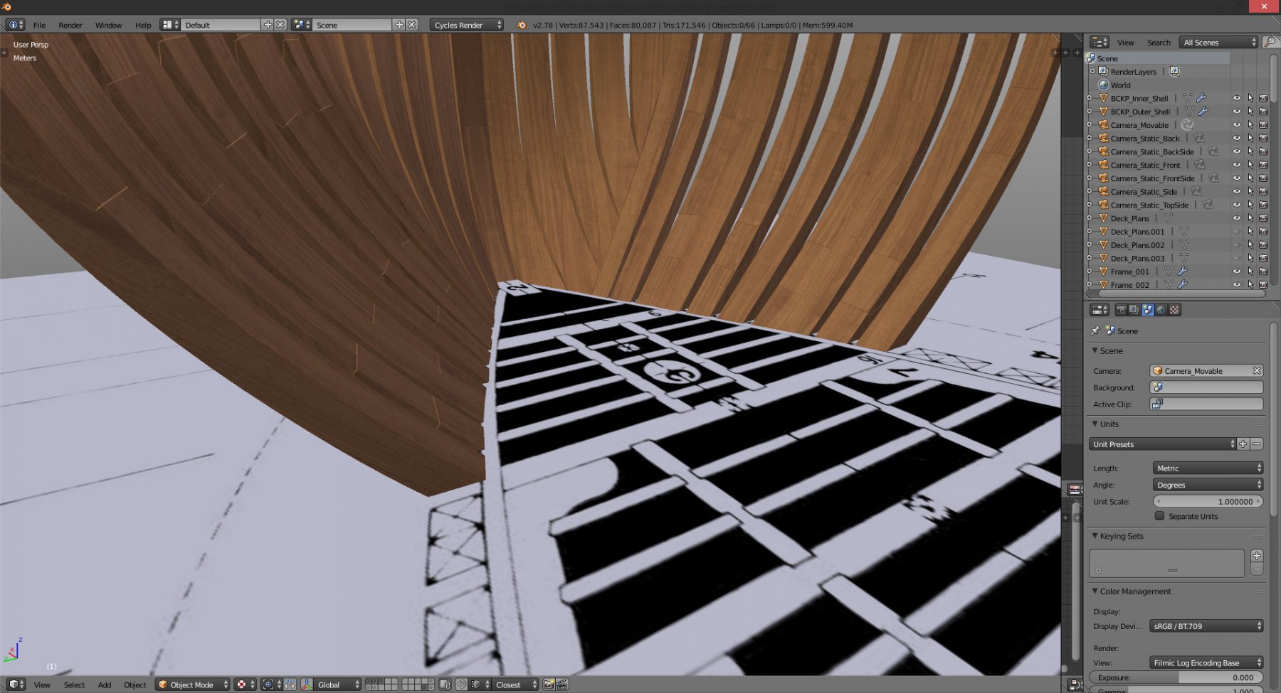
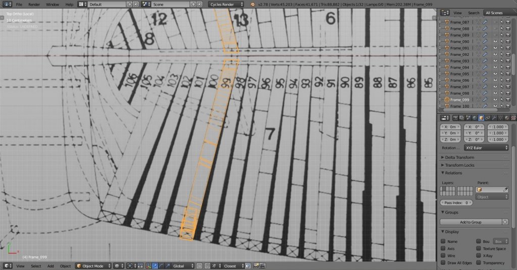
internal planking underway. although, it looks a bit off. it's hard to read from plans, especially 'cause they're not aligned, so I'm guessing quite a bit here... one question: shouldn't there be a wood of some kind at the transom to separate left and right side planking? again, plans don't show anything, yet at other isometrical drawings there is something, planks shouldn't be touching like this in the middle. any advice?

-
Yet Another Pandora 3D build
herask replied to herask's topic in CAD and 3D Modelling/Drafting Plans with Software
you know, that's one of the biggest compliments you can give to a 3d artist, to tell them it looks real. thank you Pat. and to all of you for your likes. I'm really enjoying this, I can only imagine how it is to build one for real and watch it grow on the work table... -
Yet Another Pandora 3D build
herask replied to herask's topic in CAD and 3D Modelling/Drafting Plans with Software
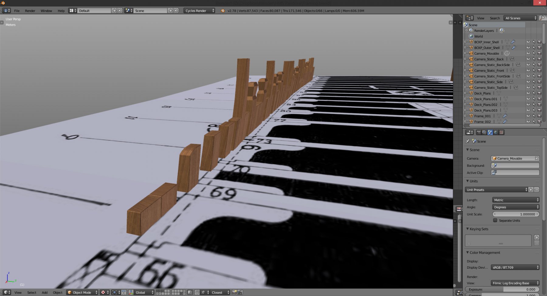
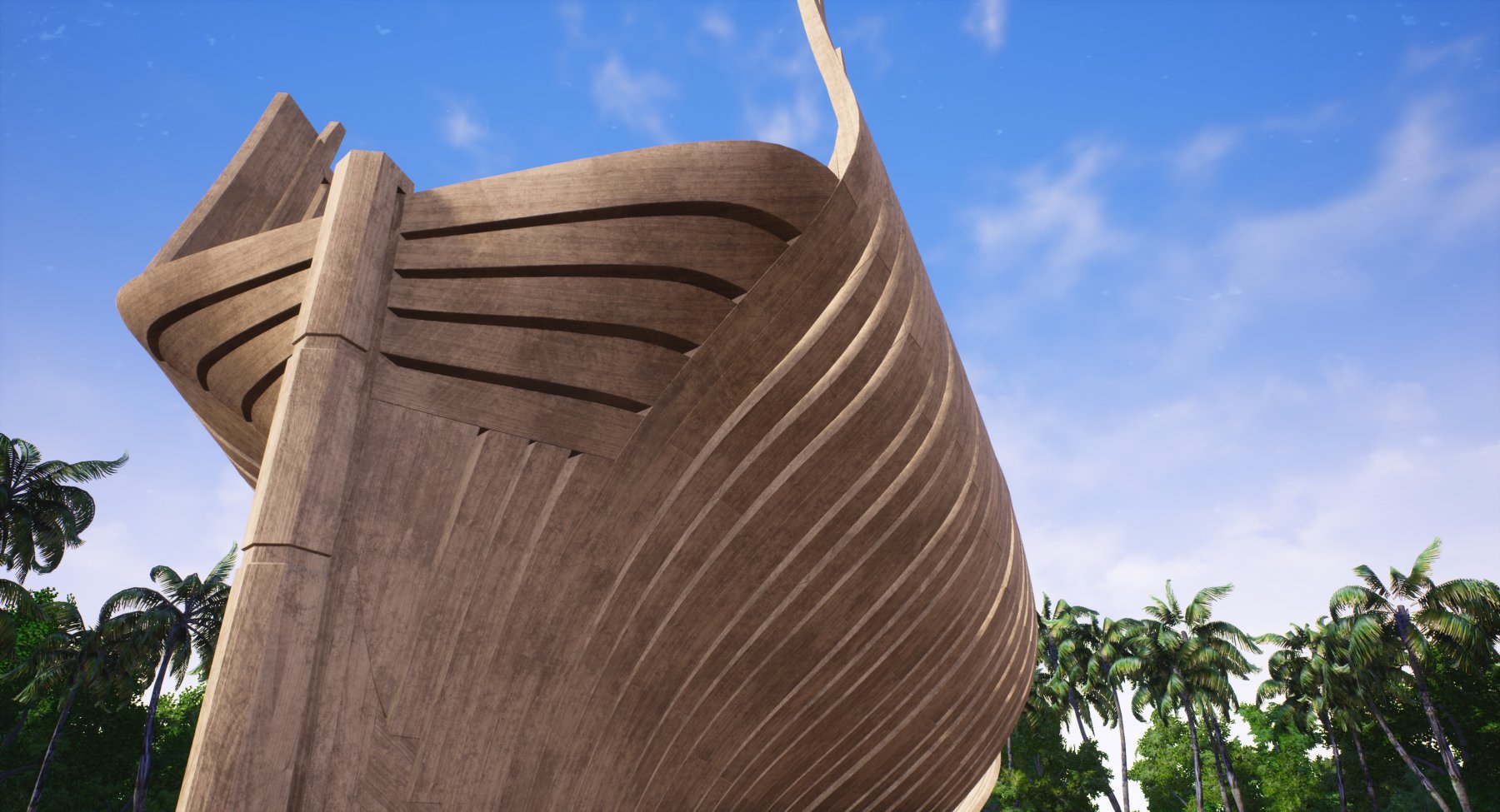
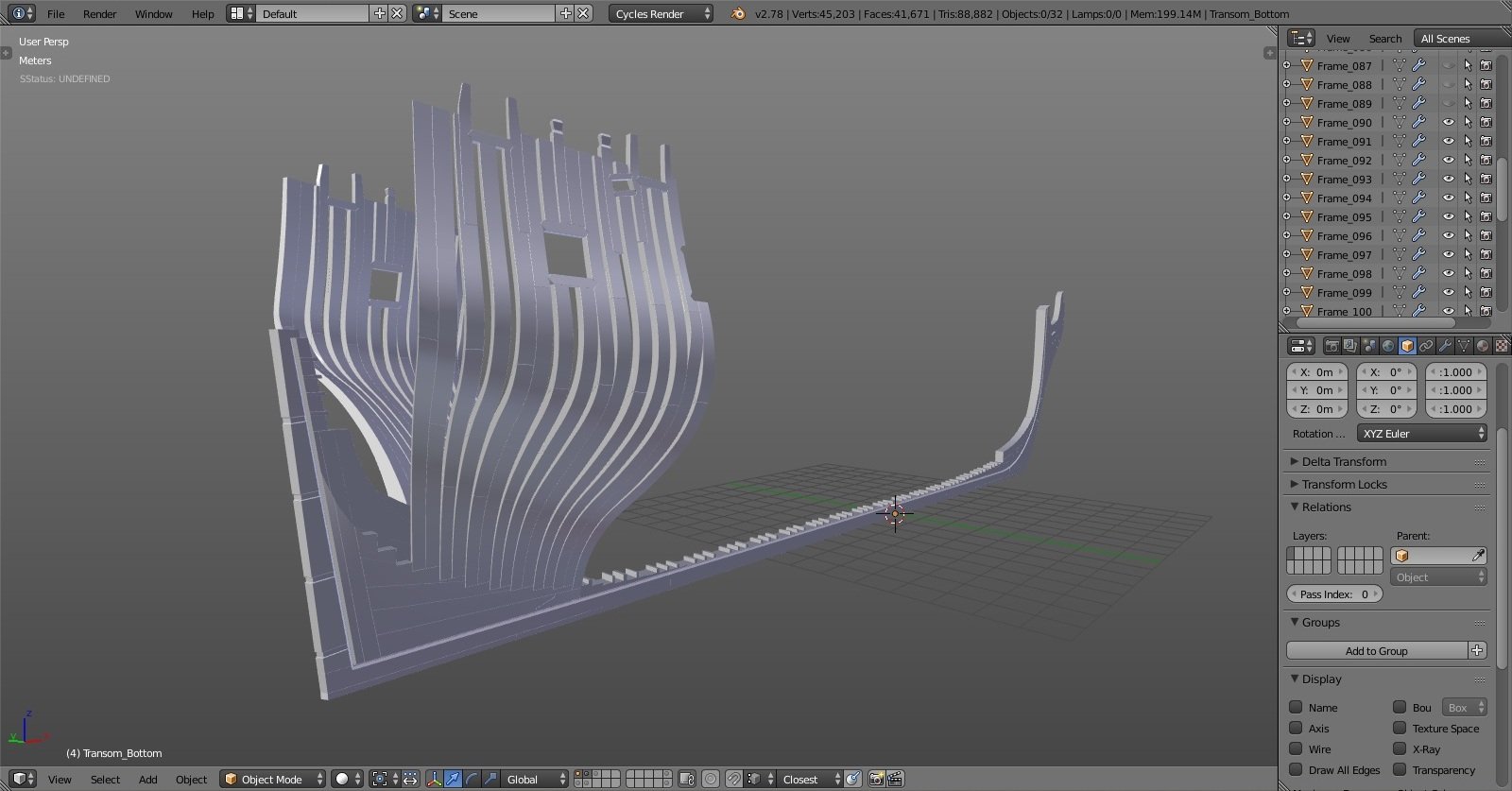
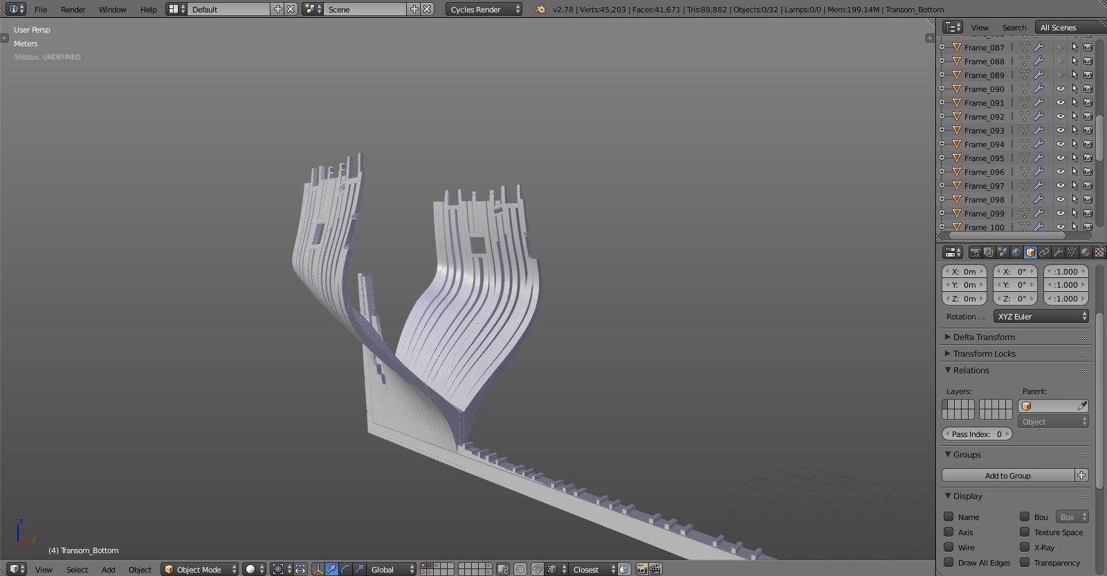
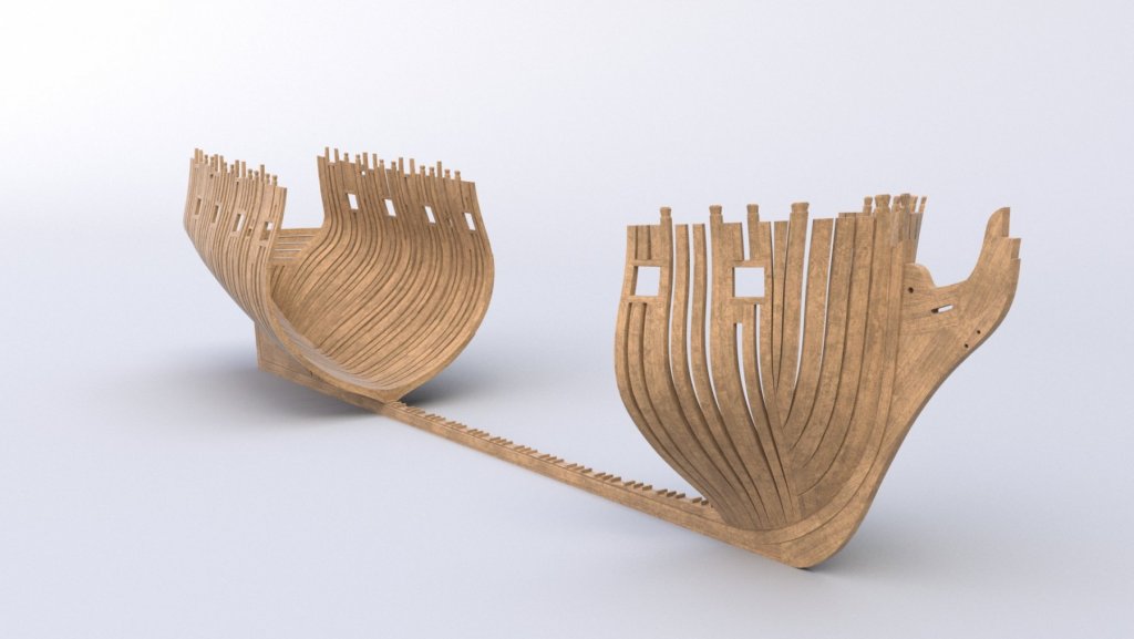
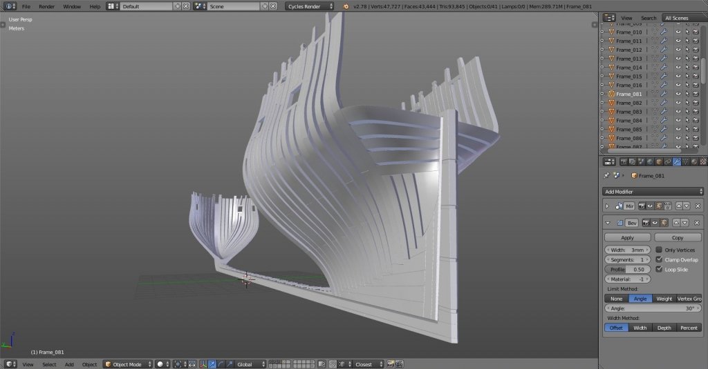
stern frames done. next is the keelson and I guess I can start with inner planking... cheers! Denis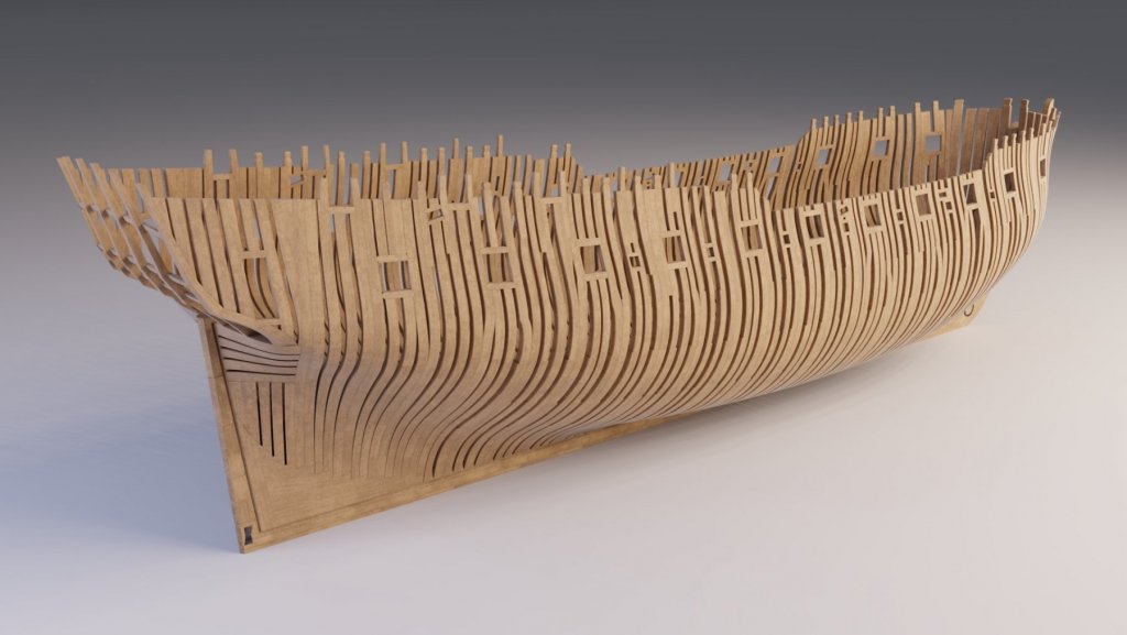
- 119 replies
-
- 12
-

-
Yet Another Pandora 3D build
herask replied to herask's topic in CAD and 3D Modelling/Drafting Plans with Software
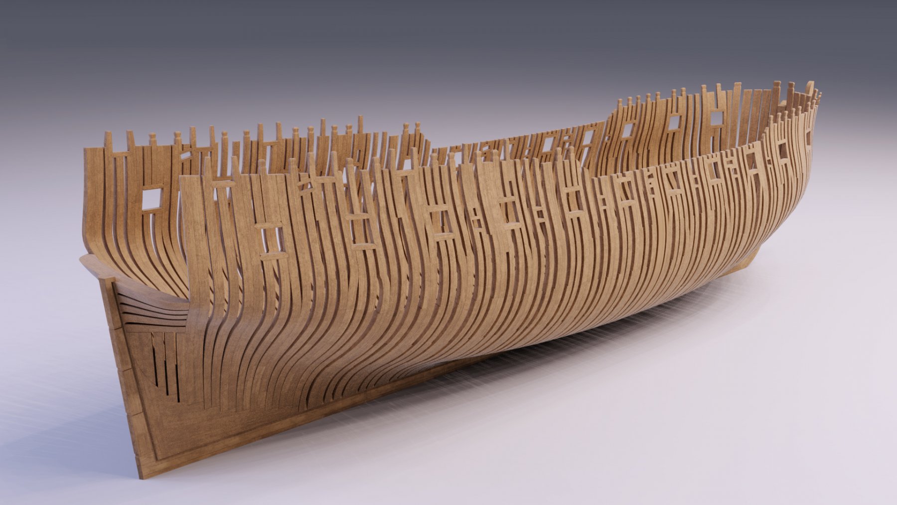
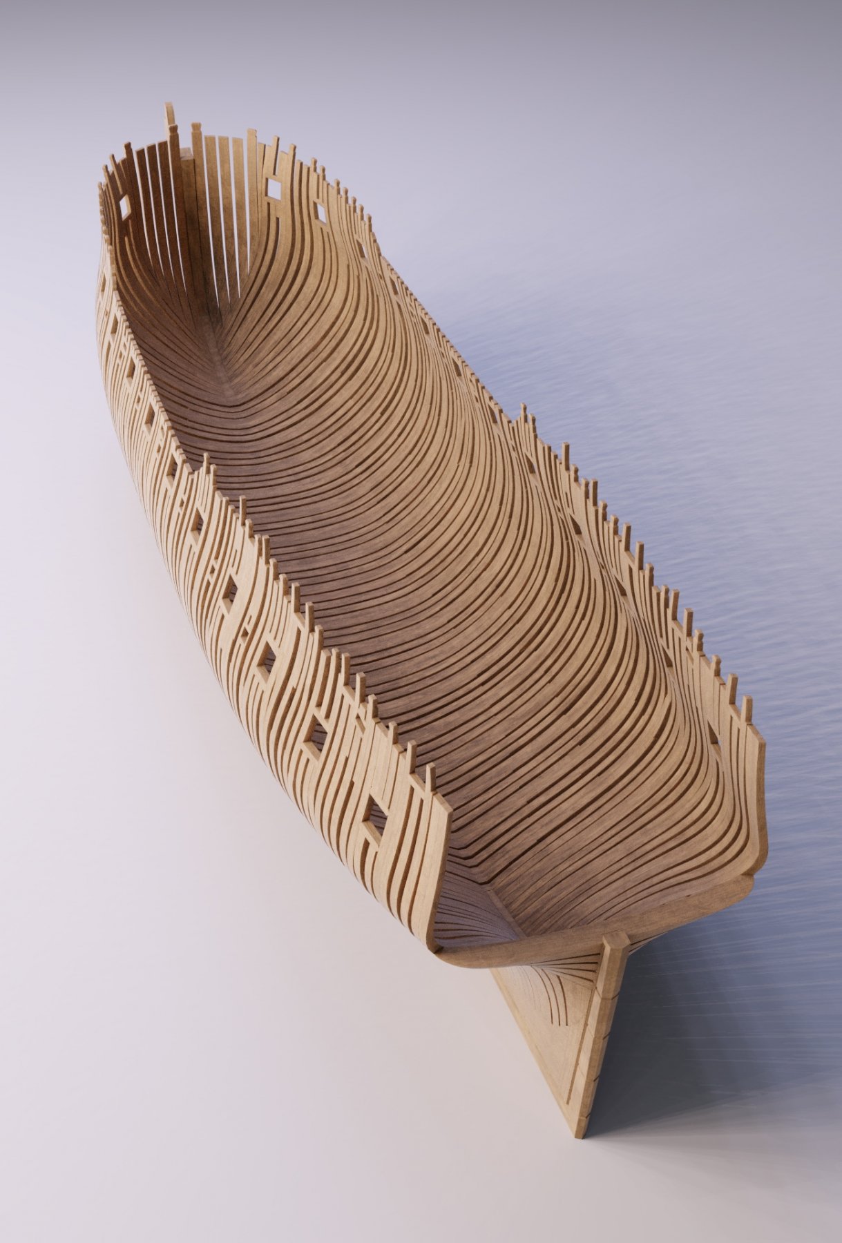
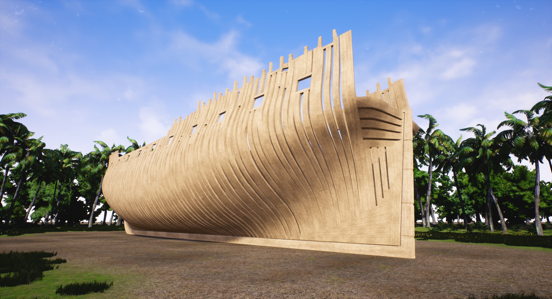
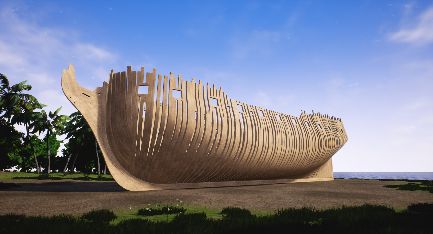
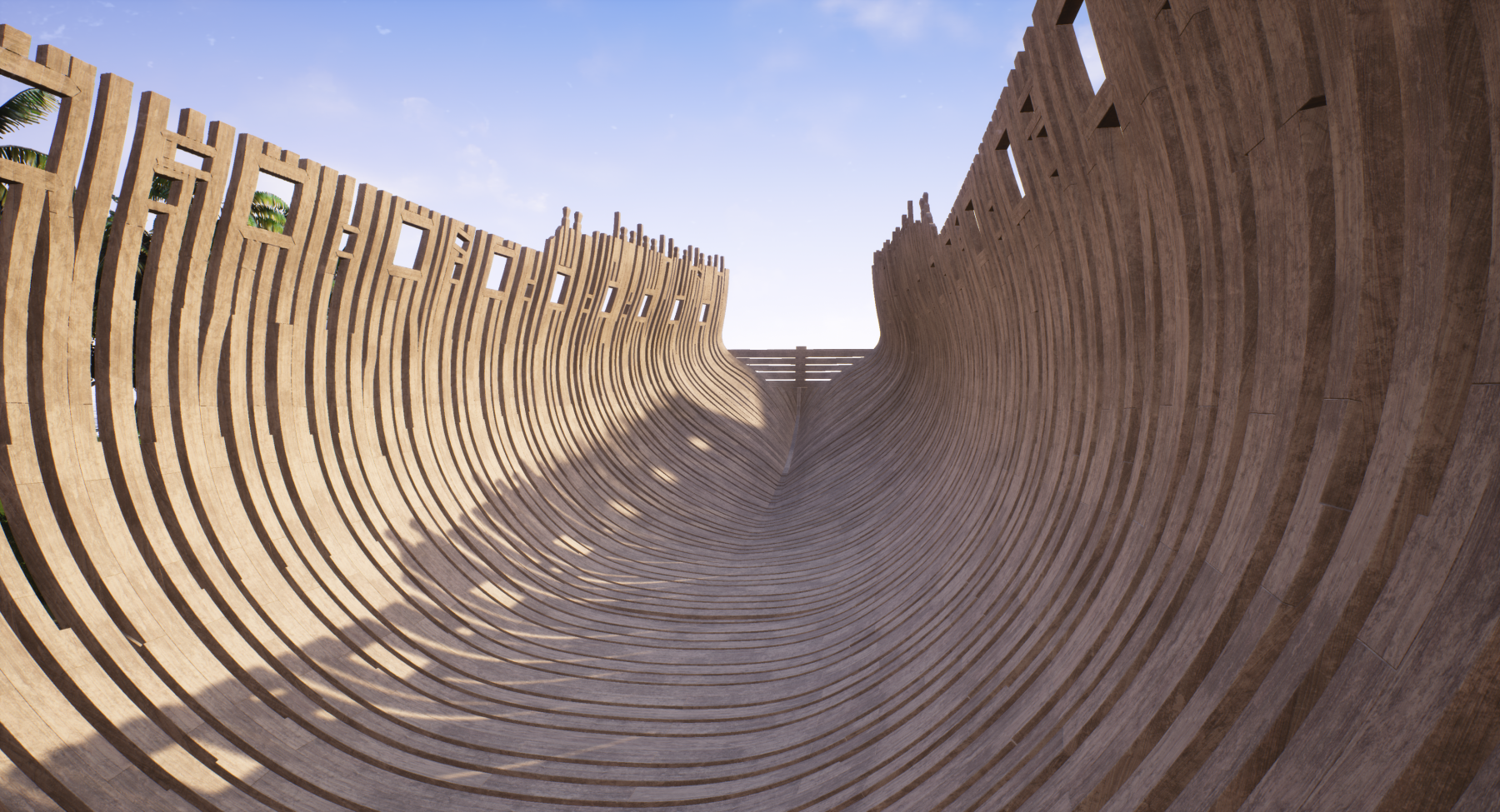
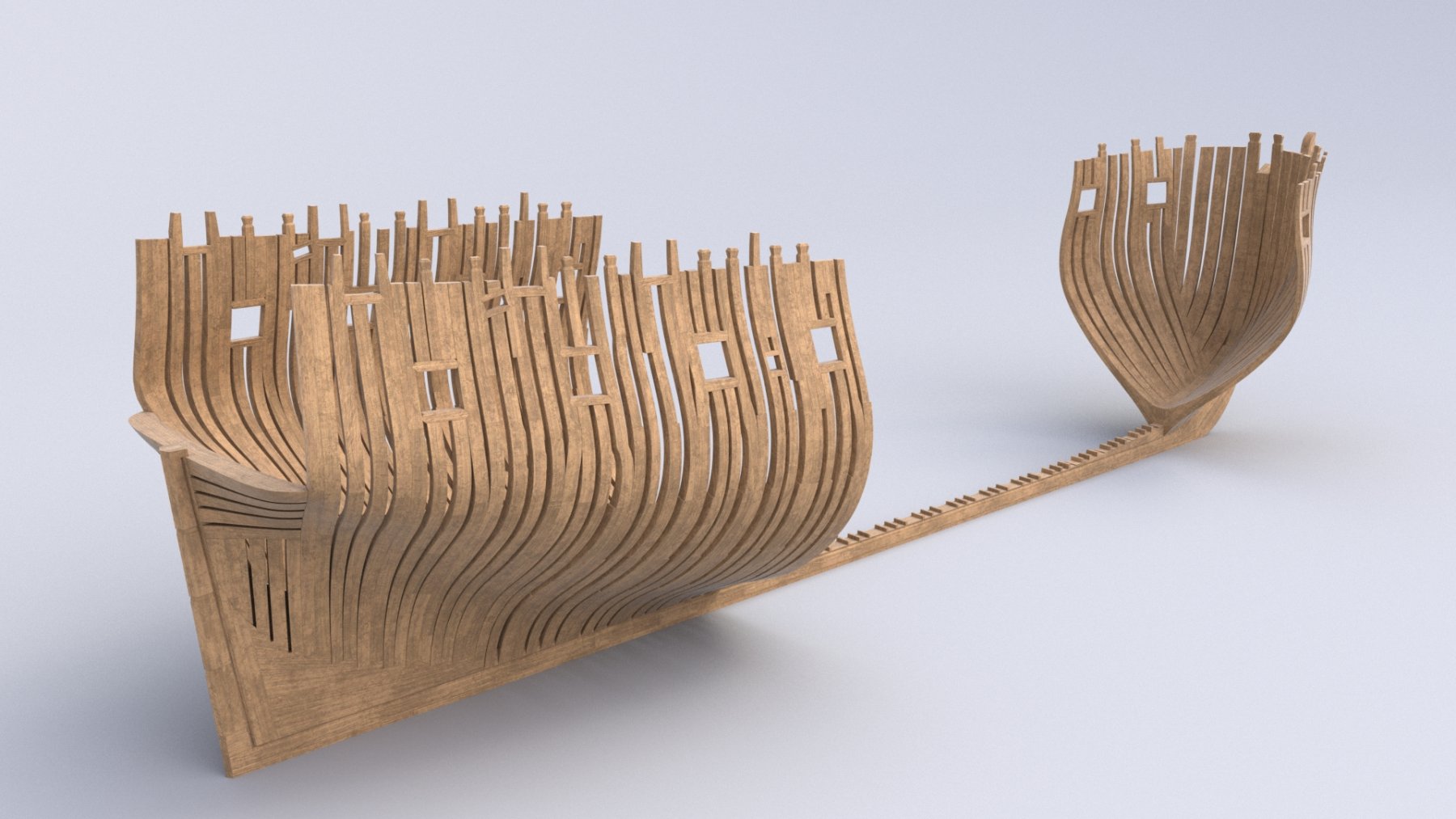
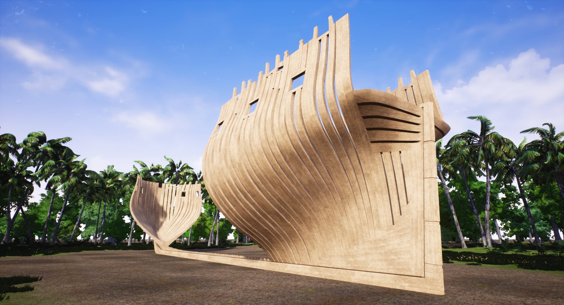
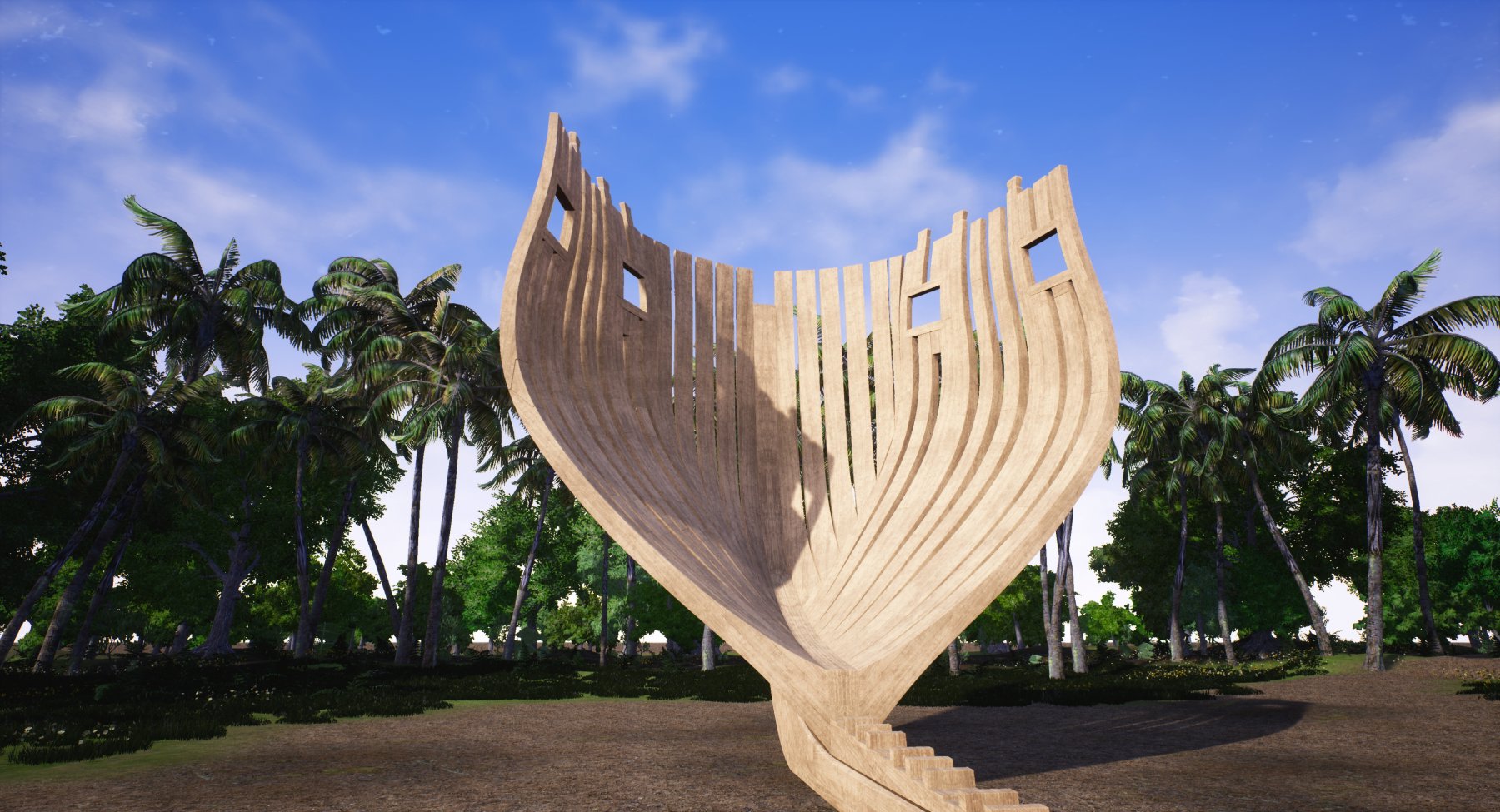
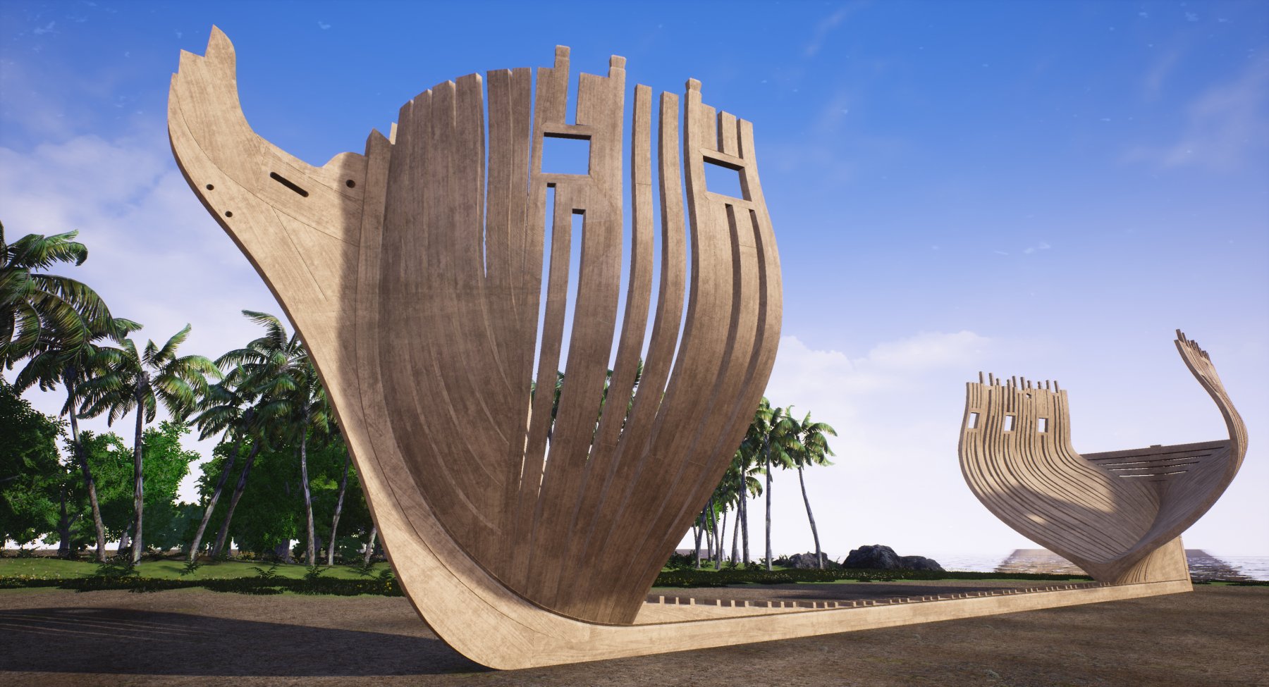
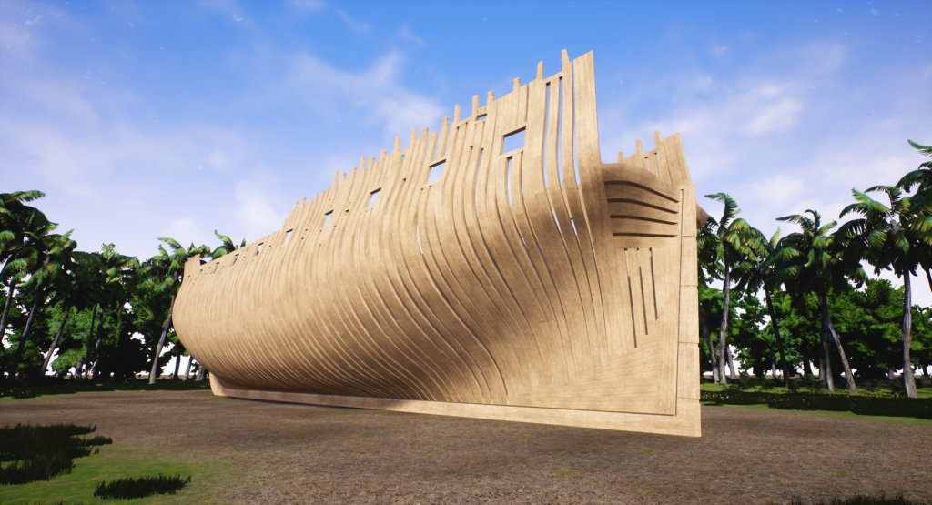
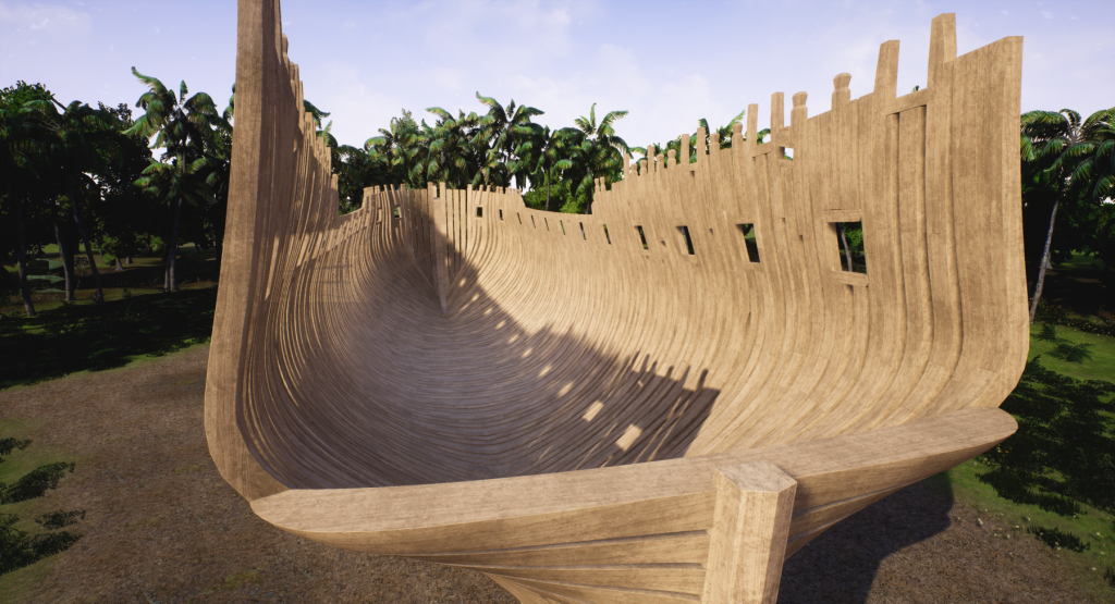
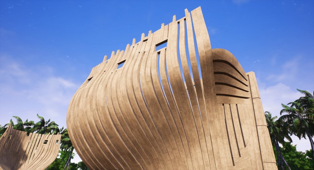
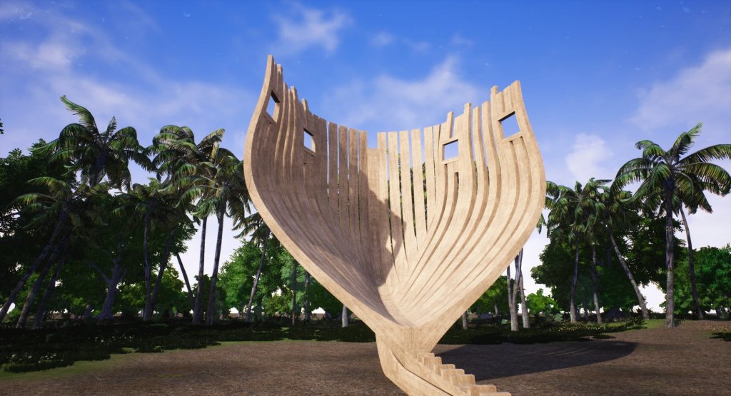
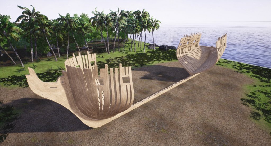
frames finished, yay! well, almost. stern frames run away before the photoshoot :-)))) and some more screenshots from UE4 showing how big it is in full scale. I've read somewhere how sailors back then were pretty short, like 1.6m, so I adjusted camera height accordingly. it must've been really impressive to see in person such a beast being built, let alone something bigger, like HMS Victory.... hope you like it! cheers Denis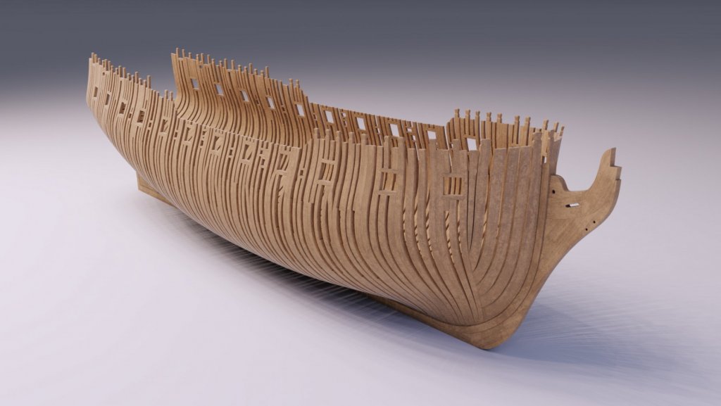


-
Yet Another Pandora 3D build
herask replied to herask's topic in CAD and 3D Modelling/Drafting Plans with Software
hey Pete, thx for jumping by! I've been using Blender since 2013, just about 4 years now. how much modeling you can do in your spare time would determine how soon you could start such project on your own. there's a lot of ground to cover: various modeling techniques (polygon modeling, edge extrusions, subdivision surface modeling, splines, NURBS, NURMS...), materials setup, lighting (still trying to figure that out properly, believe me)... but don't be intimidated by the amount of learning needed. start with something smaller and simple, and push further once you're comfortable with what you've learned. you'll progress naturally into more complex stuff. I've tried Solidworks myself, and I'm using Fusion 360 for a side job where I need certain precision. but Blender is my main go-to tool because CAD modeling is too constrained for my liking. I like to push polygons by hand and I'm much quicker in Blender than in CAD program. but yeah, you end up using the tool you find most comfortable to work with, so Blender, Solidworks, 3DS Max... whatever, as long as you have fun while modeling! ;-) cheers! Denis -
Yet Another Pandora 3D build
herask replied to herask's topic in CAD and 3D Modelling/Drafting Plans with Software
I thought chocks were those joint pieces between floor and futtocks. anyway, I didn't see any mention about their placement between the frames. I'm only guessing here, but would they go at the joints between futtocks, to stiffen things up some more? I'm almost done with the frames, btw. it's still going slow, almost like I'm doing it with real wood, LOL.... hoping to speed things up soon. -
Yet Another Pandora 3D build
herask replied to herask's topic in CAD and 3D Modelling/Drafting Plans with Software
ahem...me again with the question. I tried googling but no (precise) luck. about those spacers between the frames, where would they go on Pandora? is there a certain rule about their placement or can they be placed arbitrarily by a guy who is still learning about the ship building? :-) any help appreciated! cheers! Denis -
Pandora by marsalv - FINISHED - 1:52
herask replied to marsalv's topic in - Build logs for subjects built 1751 - 1800
thank you for the explanation, Marsalv. -
Yet Another Pandora 3D build
herask replied to herask's topic in CAD and 3D Modelling/Drafting Plans with Software
thank you Don. yes, the plans are from AoTS book. I tried to align them in photoshop the best I could but the stretching was horrible. even the space between 3 station lines wasn't equal, let alone for the whole length of ship. that's why I needed to do the drafting. I guess one could build individual pieces, like deck beams and such by finding their real dimensions and not worry much about distortion in plans. I'll dig some more through the book you suggested to find some measures, or I'll just lift them from drawings and adjust to my ship. in the end, this is a computer model where I can get away with inconsistencies more easily than on a real ship model. if I see this through the end, and still wnat to build another, I might save some cash and buy a book with proper plans for my next build, just to make things easier... I'm already eyeing HMS Bellona/74-gun ship and Timbering plans from Ancre. and Bonhomme Richard, and HMS Bounty, and Le Fleuron and.... oh man, what have I gotten myself into? -
Yet Another Pandora 3D build
herask replied to herask's topic in CAD and 3D Modelling/Drafting Plans with Software
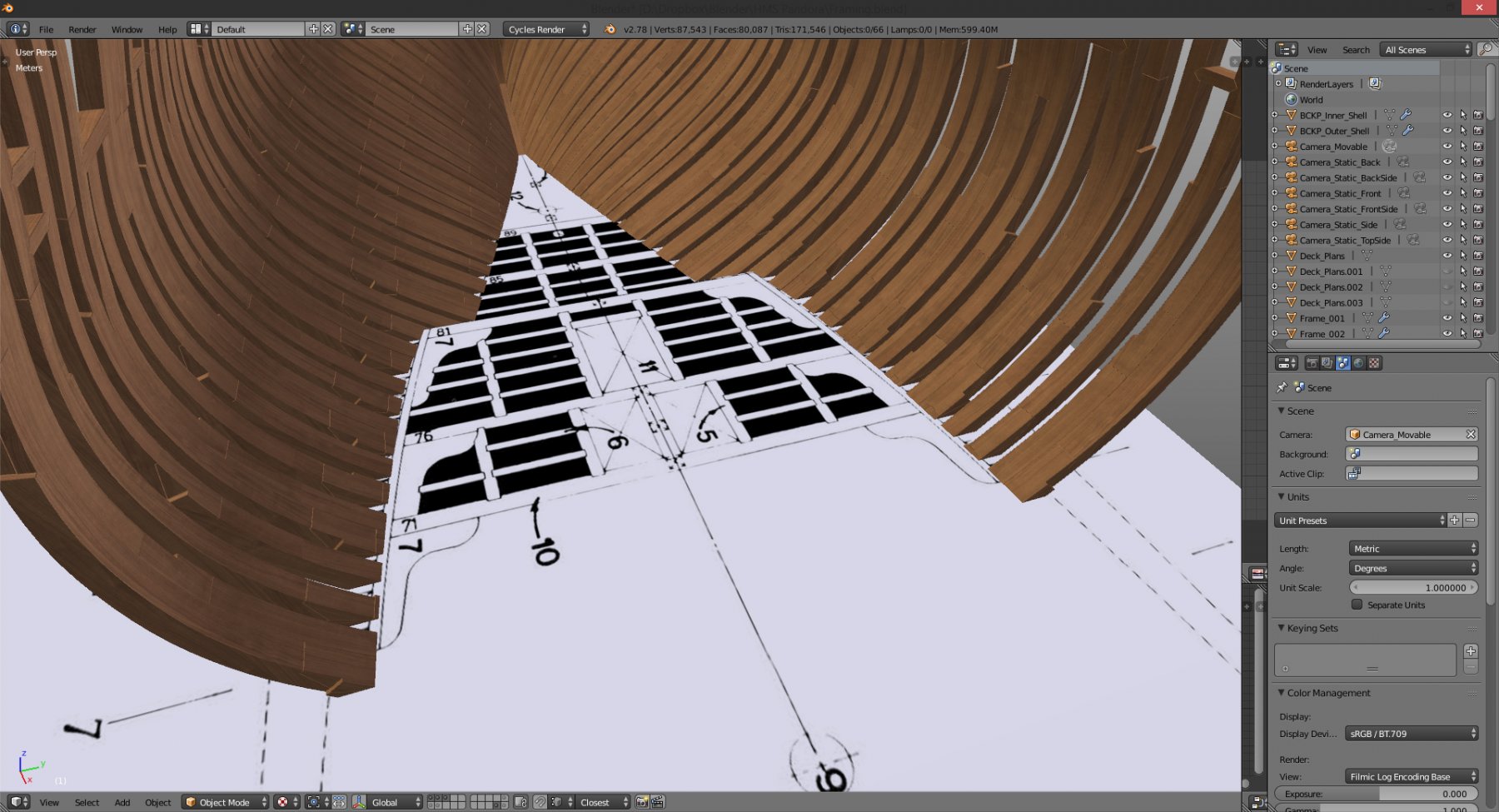
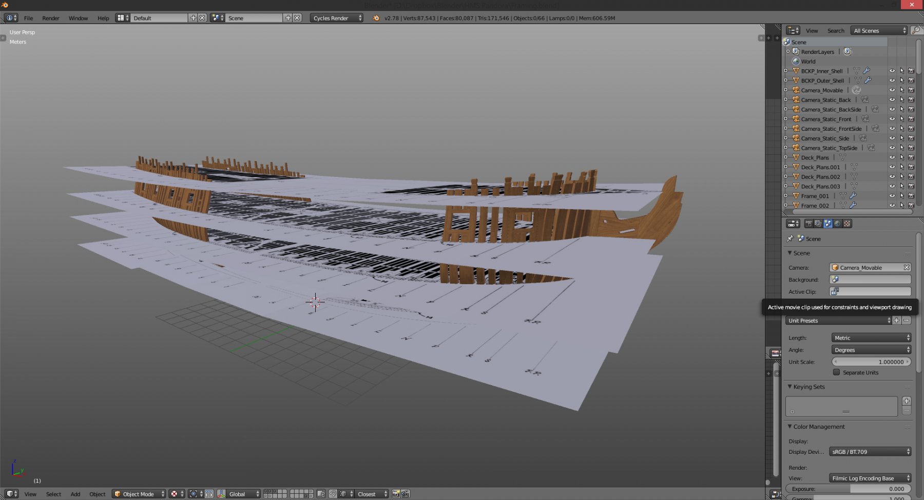
thank you Don, that book is huge. I'm sure I'll find something there. although I can't do much regarding frame thicknesses anymore without getting everything out of alignment. but, I laid out deck plans on the model and frame thicknesses seem OK (more or less). it's some differences in hull breadth at some places that worry me. I'm pretty sure I did the drafting OK, but now deck width varies a bit along the length. should I deform my frames to be aligned to deck plans or should I stick with my drafting and adjust decks according to faired hull shape? I can easily manipulate that deck plan to fit perfectly inside the modeled frames. and that should be the correct approach, right? considering I haven't done complete drafting, where the decks would be adjusted as well... here are the pics with decks laid out... oh, and thank you all for the likes and comments. ;-) cheers! Denis


-
Pandora by marsalv - FINISHED - 1:52
herask replied to marsalv's topic in - Build logs for subjects built 1751 - 1800
fantastic build! one question, if I may. what is that red frame (for the lack of correct word - a newcomer here ) in front of the stove, and why is it there? doesn't that make approach to the stove rather difficult? cheers! Denis -
Yet Another Pandora 3D build
herask replied to herask's topic in CAD and 3D Modelling/Drafting Plans with Software
making progress. currently I'm busy with another project, but that's due soon, so I hope I'll gain some speed... cheers! Denis


-
Yet Another Pandora 3D build
herask replied to herask's topic in CAD and 3D Modelling/Drafting Plans with Software
thank you. now that I know what to search I'll do some digging. I don't know if I'm going to invest a lot of time into a dockyard since the ship is main star here, but an appropriate setting would be nicer than a Caribbean beach... ;-D -
Yet Another Pandora 3D build
herask replied to herask's topic in CAD and 3D Modelling/Drafting Plans with Software
hm, now that's an idea. I always associate sail ships with pirates, and Caribbeans and palms, hence the scene. do you have any drawings or links where I could find more about such dockyard and how it looked? -
looking good. great modeling... ;-) Denis
-
Yet Another Pandora 3D build
herask replied to herask's topic in CAD and 3D Modelling/Drafting Plans with Software
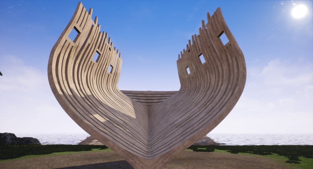
that last post got me thinking, what if we could see how this ship would look like in full size? I've quickly set up a scene in a video game creation software called Unreal Engine 4. in it I can move the camera around as if I'm walking right next to the frames. the camera height is about 1.65m (cca 5.4 feet) which is exactly my eye height, so you have some reference about the size. ;-))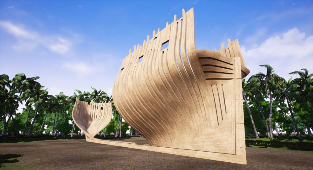


- 119 replies
-
- 15
-
-
Yet Another Pandora 3D build
herask replied to herask's topic in CAD and 3D Modelling/Drafting Plans with Software
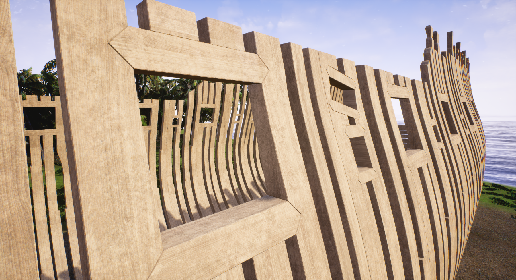
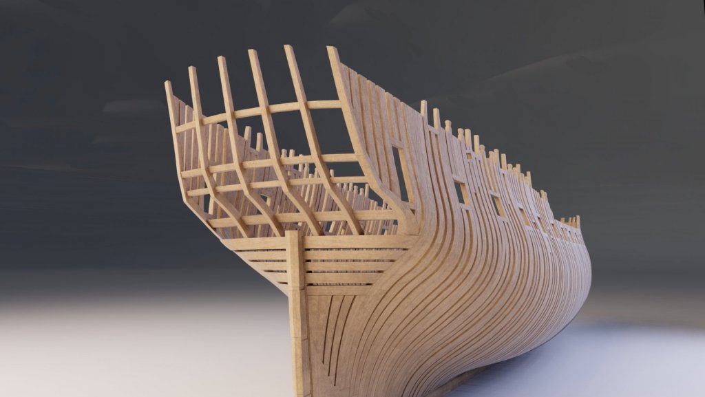
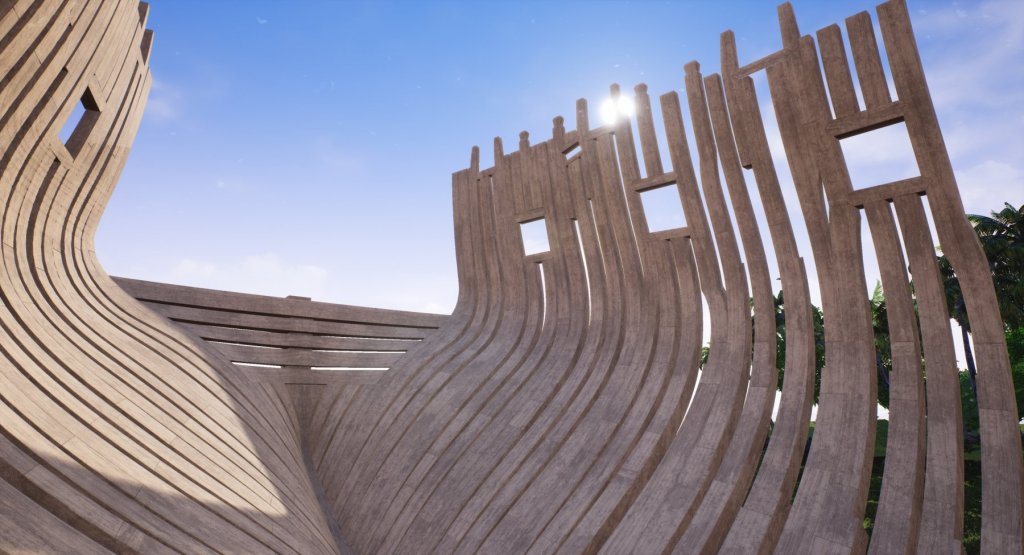
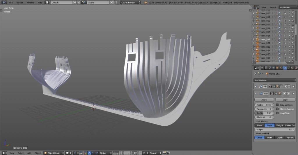
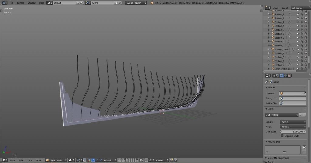
thx Mark. well, never say never. Blender is free, and there are a lot of good tutorials on-line. when you have nothing better to do give it a go, you might be surprised... :-) hawse piece and forward kant frames done. I still have to drill holes (err... whatever they're called :-D), but I'll leave it for later because I'm not sure how well aligned they are on plans... I can do that later when I start detailing... trying to take a shot from eye-height, more or less. I can only imagine how it would be to stand beside real frame this big...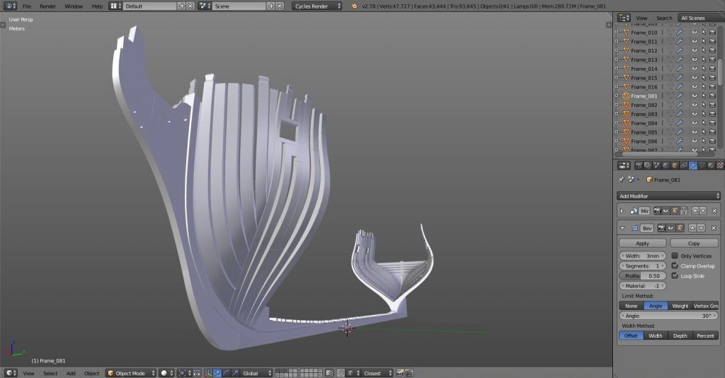
-
Yet Another Pandora 3D build
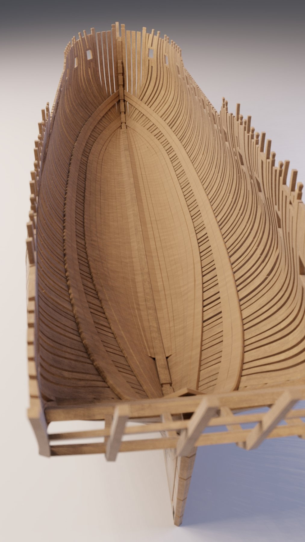
herask replied to herask's topic in CAD and 3D Modelling/Drafting Plans with Software
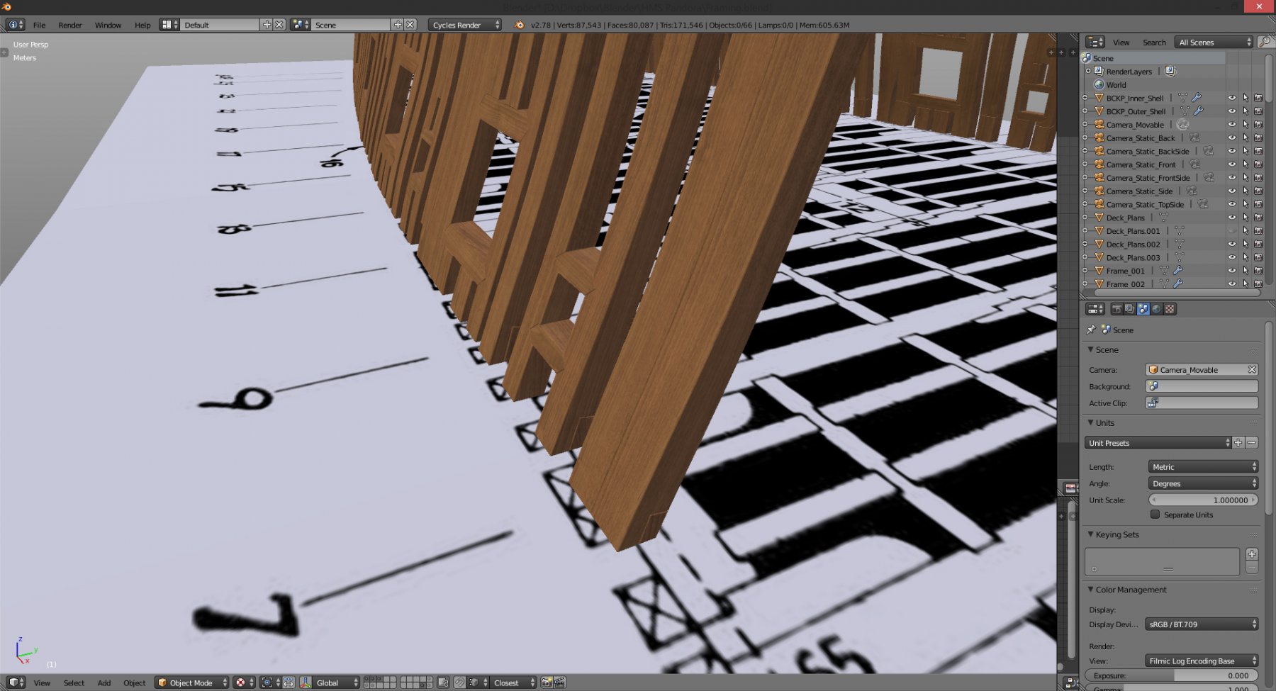
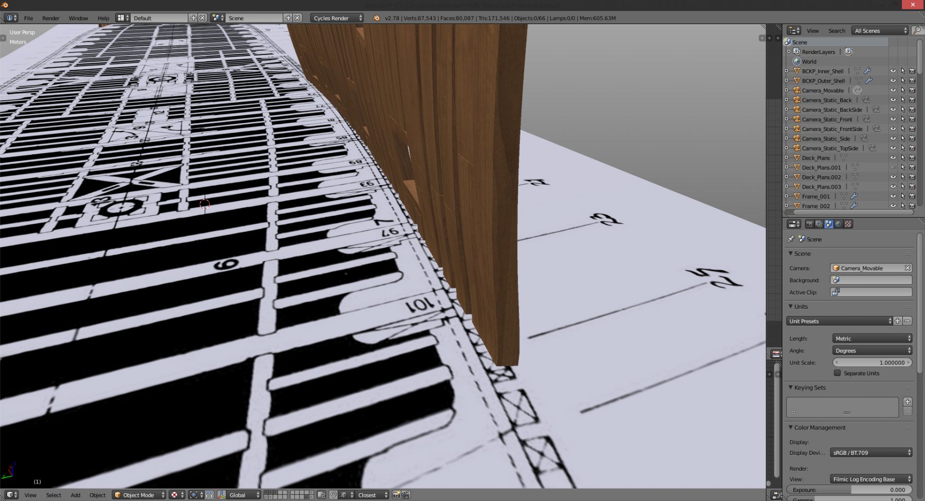
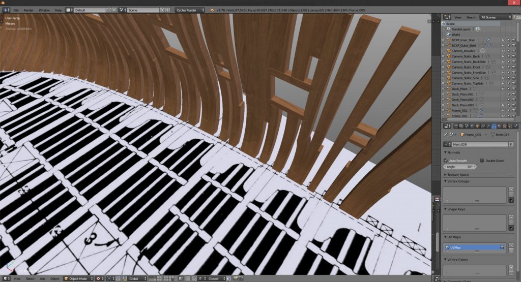
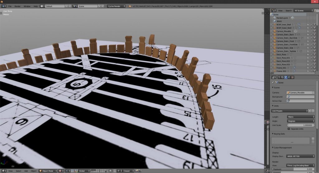
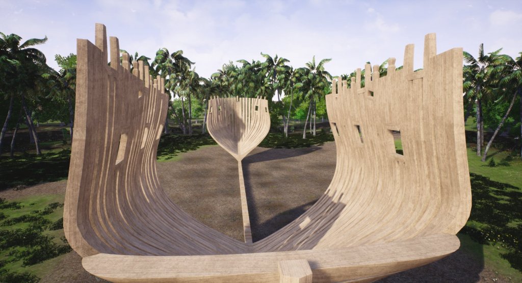
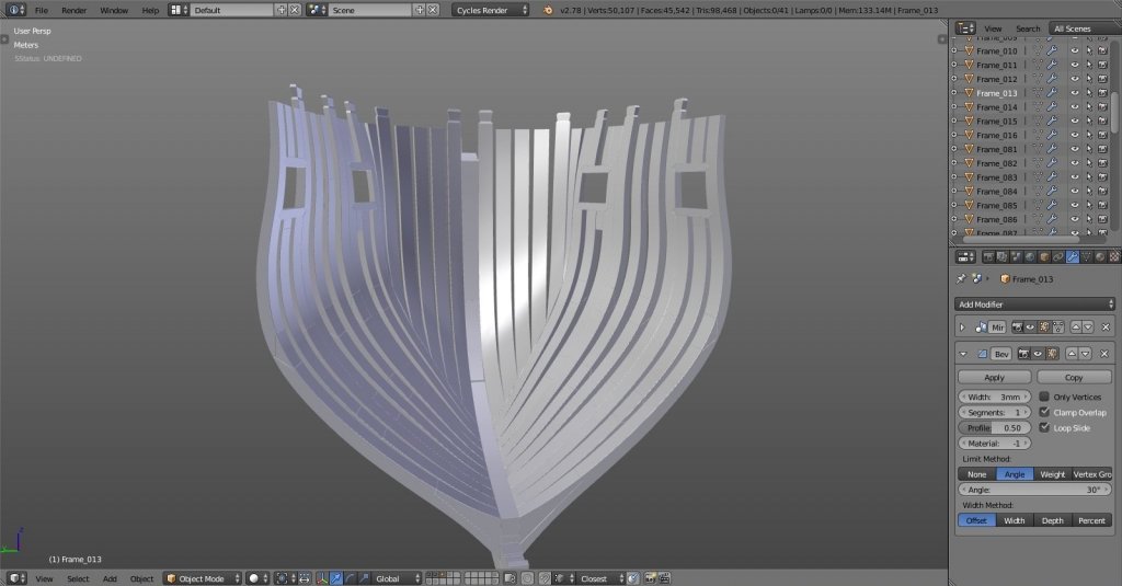
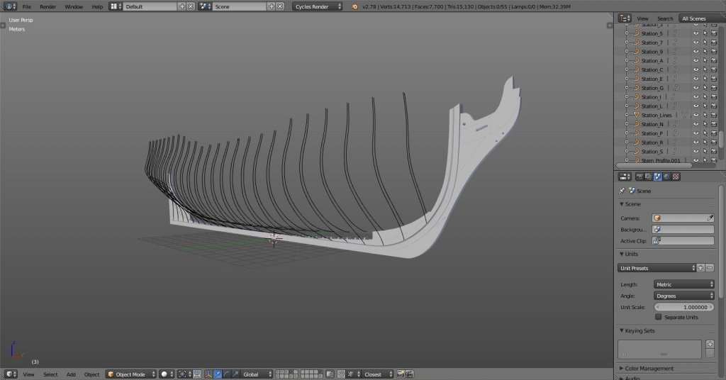
ok, aft kant frames done! as you can see from images, half-breadth framing plan isn't really aligned with profile plan. I've cut straight lines looking from top, which doesn't look good when viewed on profile plan. that's how I figured I'll need to do the drafting back then. I just hope I did it right. quick cross-checking the deck plans with finished hull shell showed that I managed to get it pretty close. I hope it'll all be well once I get to building the decks… and, this is the point where I am at right now. next I'll do hawse piece and fore cant frames. I hope you'll find this build interesting as well as the other ones. I know this isn't the real deal, and I guess many of you have already noticed tons of errors. since this is my learning build feel free to point each and every one of them should you wish so. the more I learn now the better the next one will be. thanks and stay tuned for more...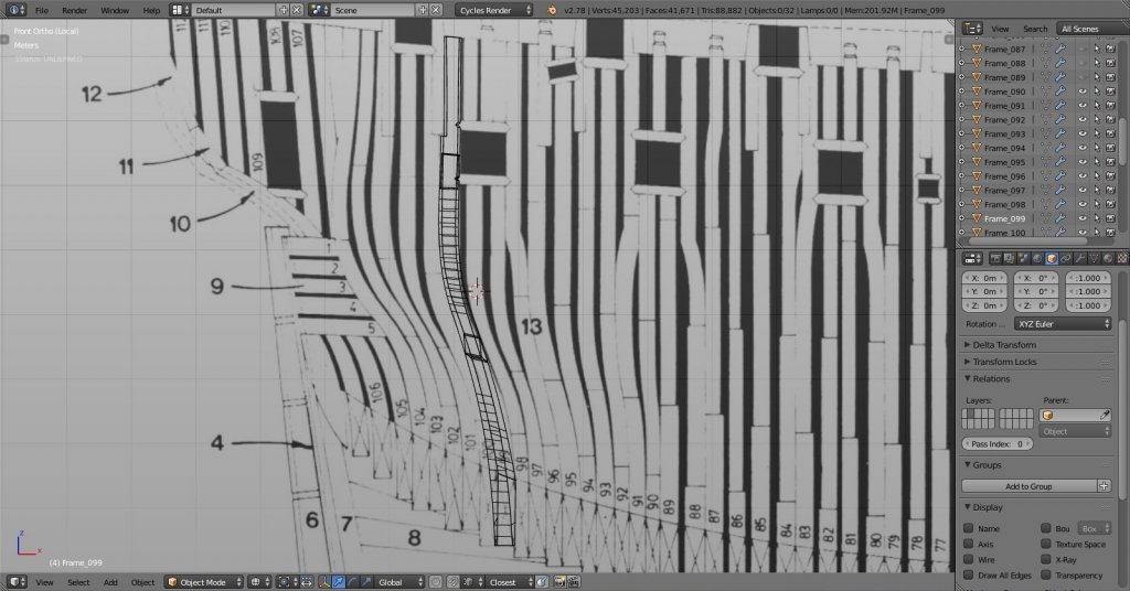
- 119 replies
-
- 10
-
-
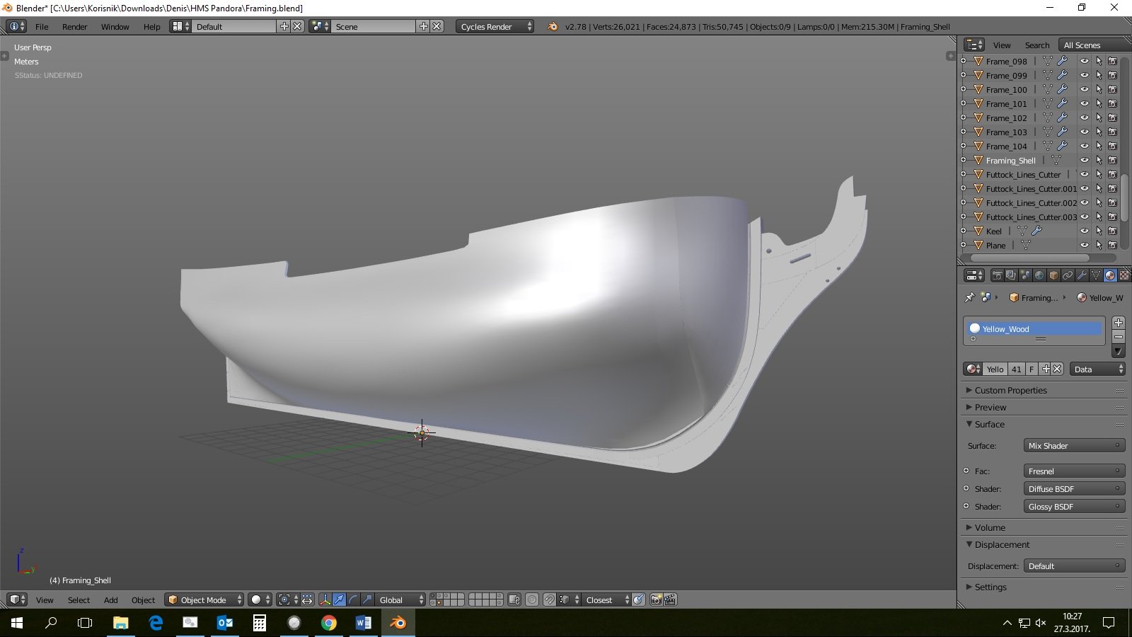
Yet Another Pandora 3D build
herask replied to herask's topic in CAD and 3D Modelling/Drafting Plans with Software
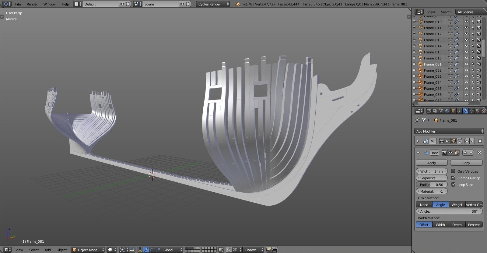
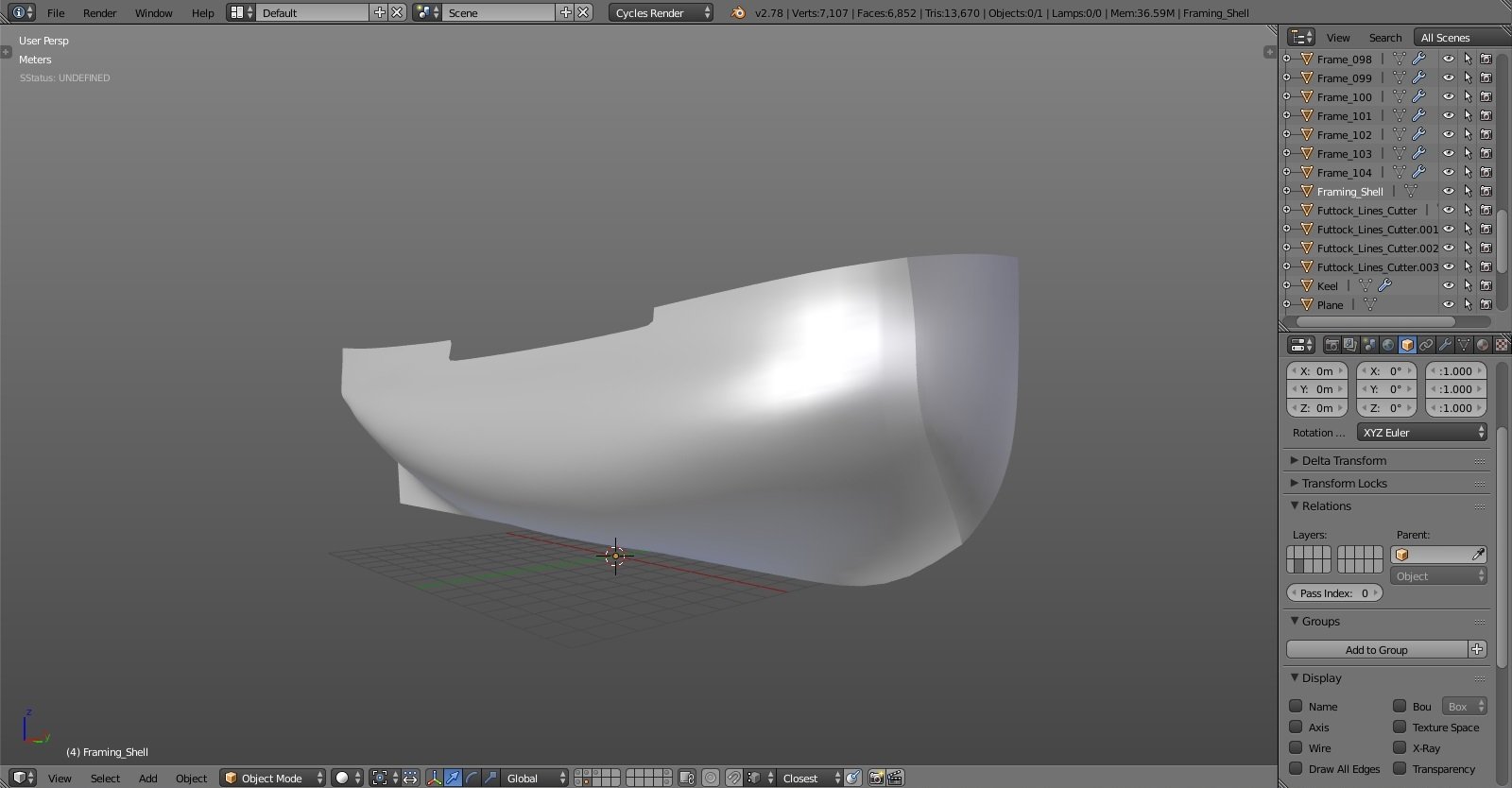
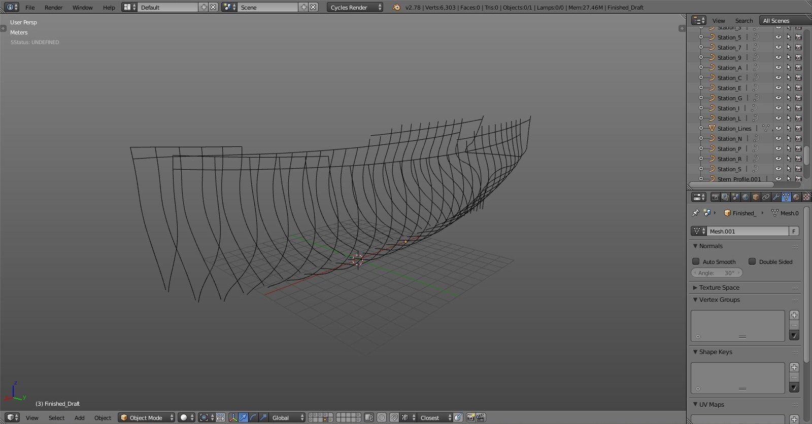
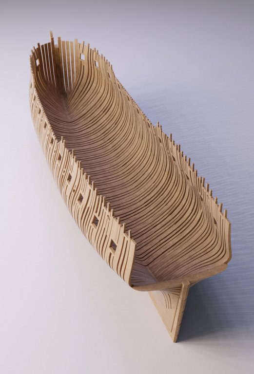
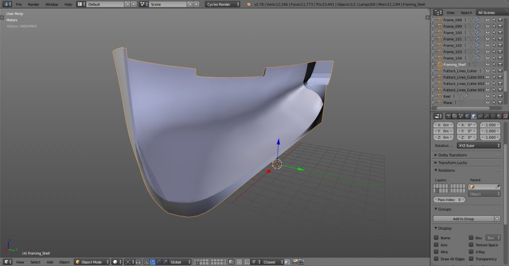
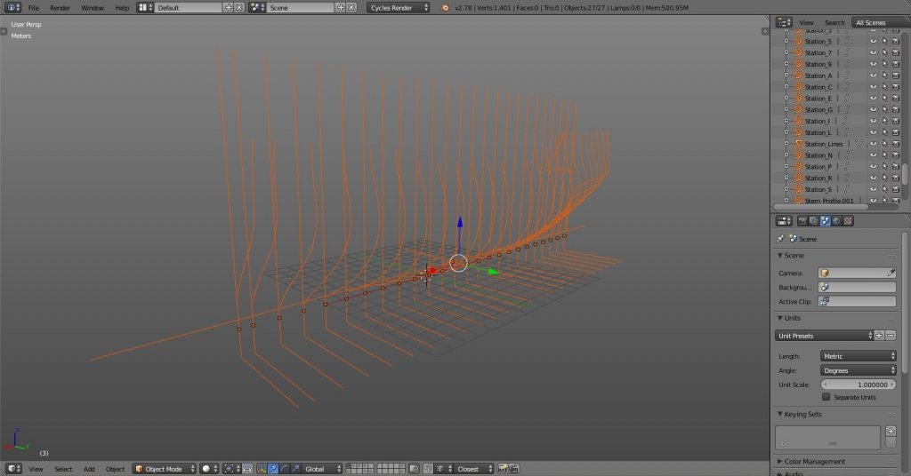
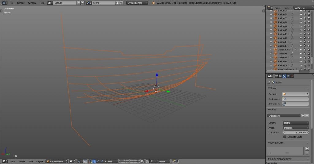
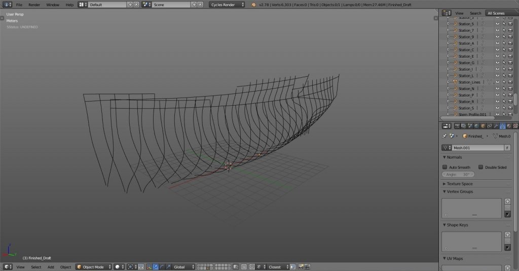
after I finished drafting plans I just connected all of the new station lines to get the outer hull shell. I couldn't find any info on the exact thickness and tapering of the frames toward the top, but I did read through some data about dimensions of 24-gun ship. the data there also wasn't exact so in the end I settled with 11", 10" and 9" thickness at futtocks going from keel upwards. pretty unprecise, I know, but again, this is 3D build where I can more easily adjust dimensions than with real wood. I just hope the margin of error won't accumulate that much later on. the shell is done, it looks OK placed on the keel. I guess I can start cutting the frames.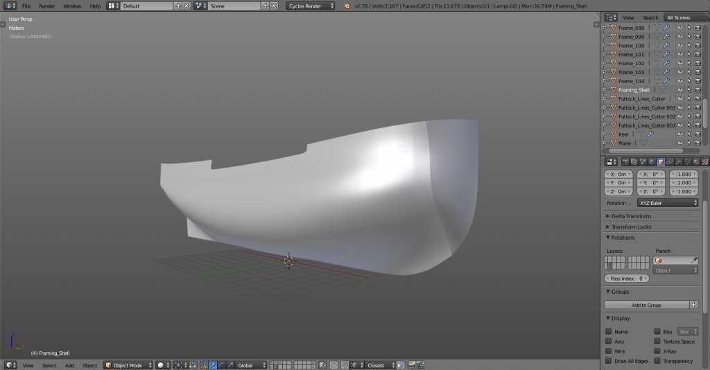
-
Yet Another Pandora 3D build
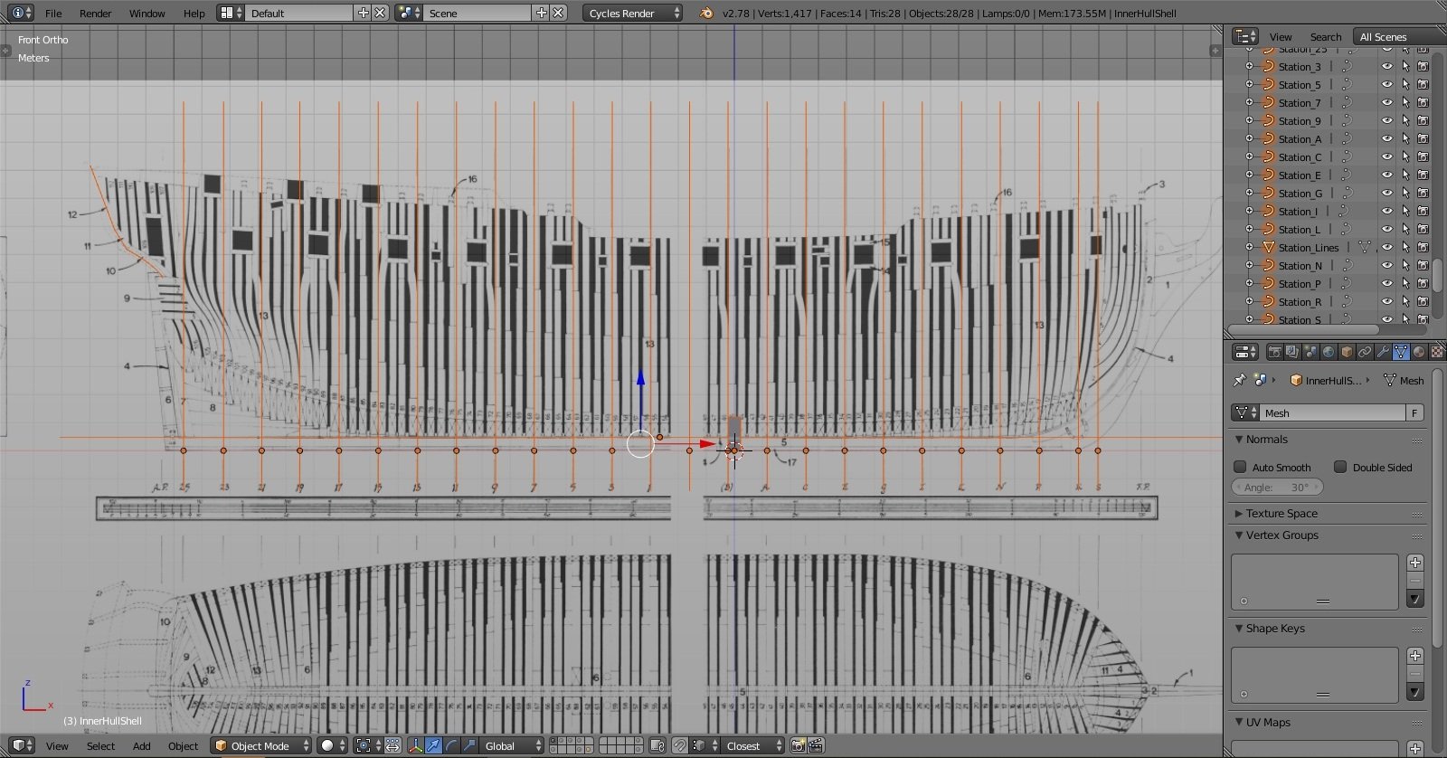
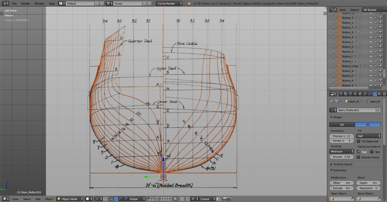
herask replied to herask's topic in CAD and 3D Modelling/Drafting Plans with Software
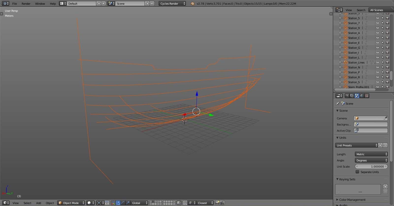
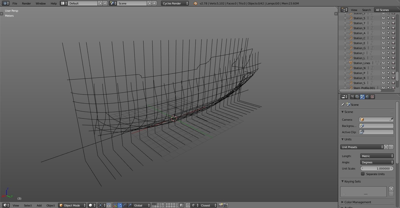
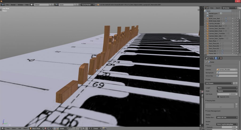
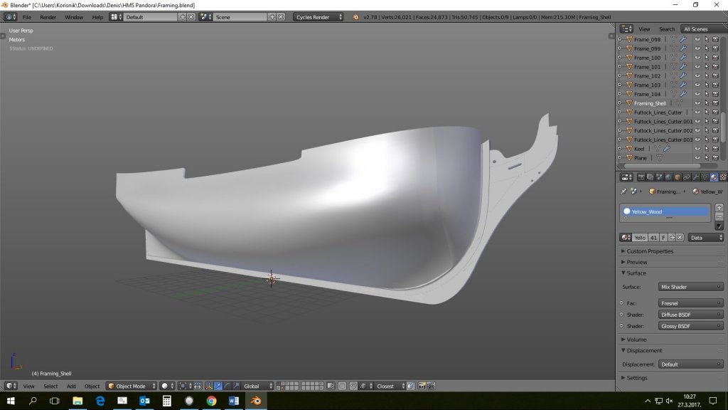
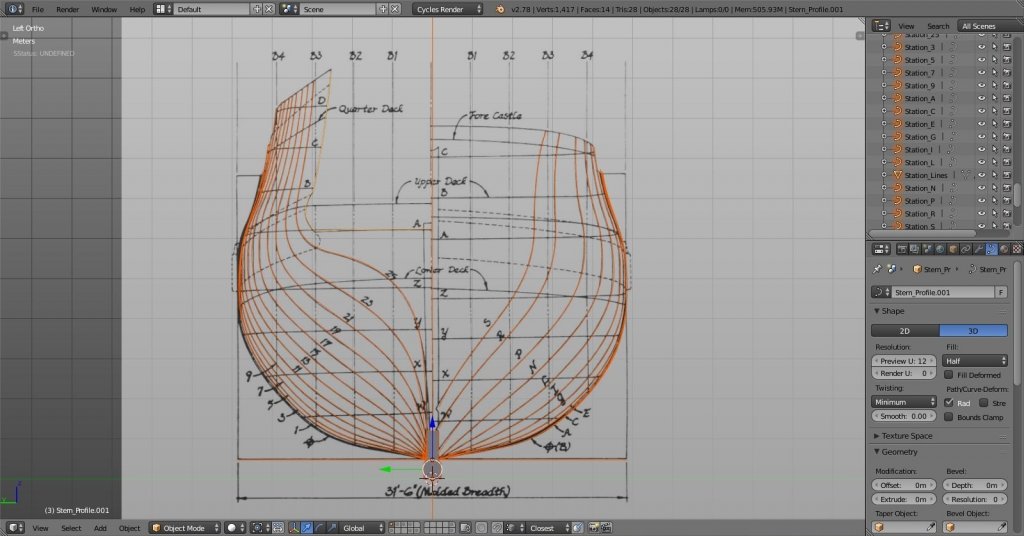
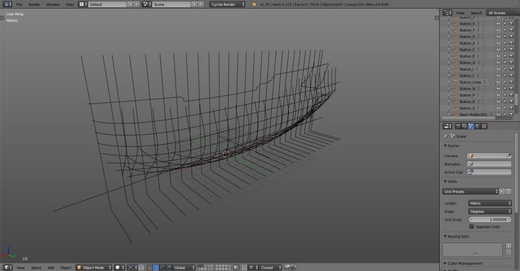
I'll use ppddry's method he used for his solidworks build, I'll make hull shell from which I'll cut frames. if I had framing plan with all frames drafted I would have done it that way but this method will have to work for now… tracing the scanned plans: finished drafting: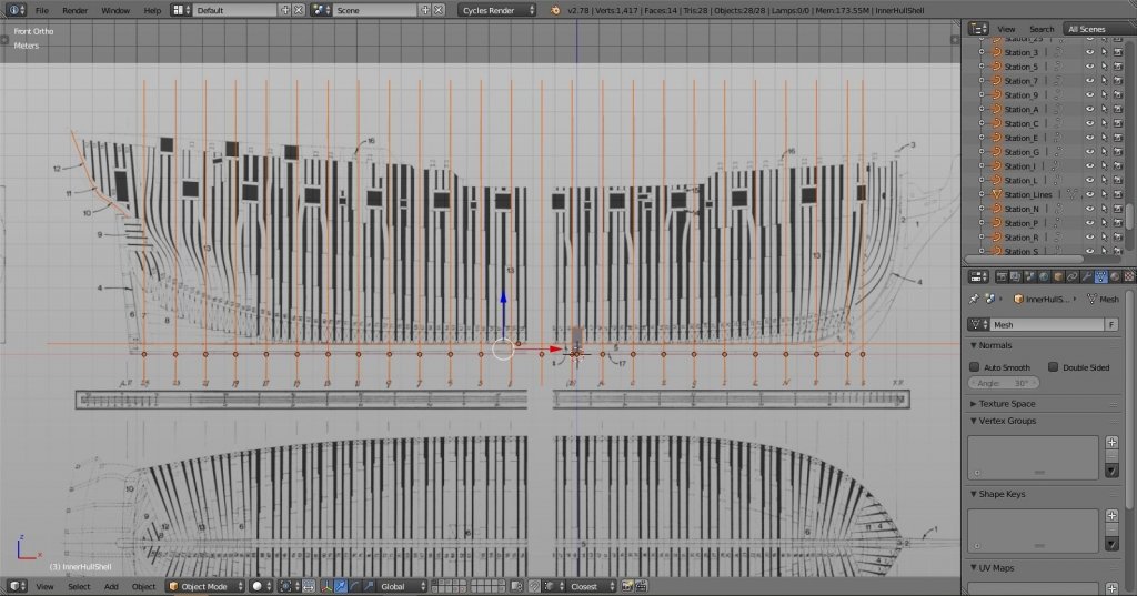
-
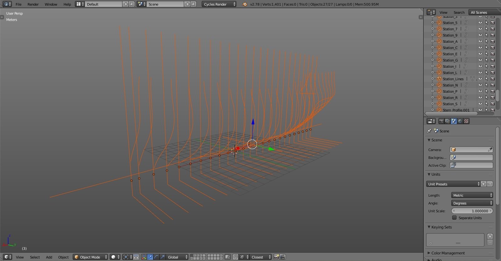
Yet Another Pandora 3D build
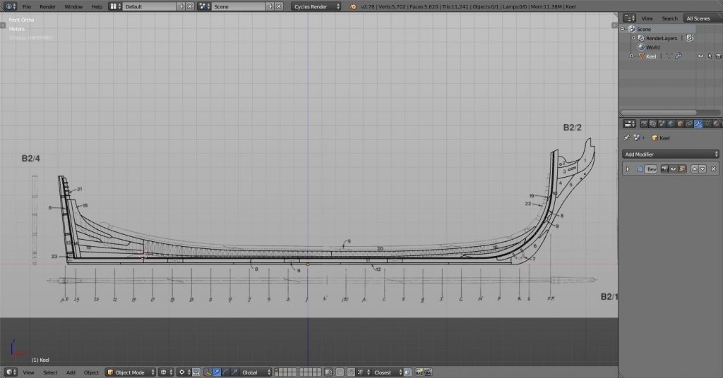
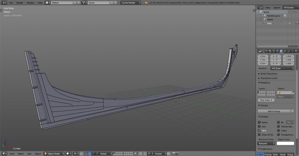
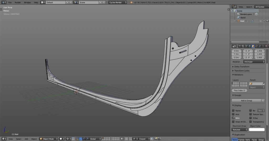
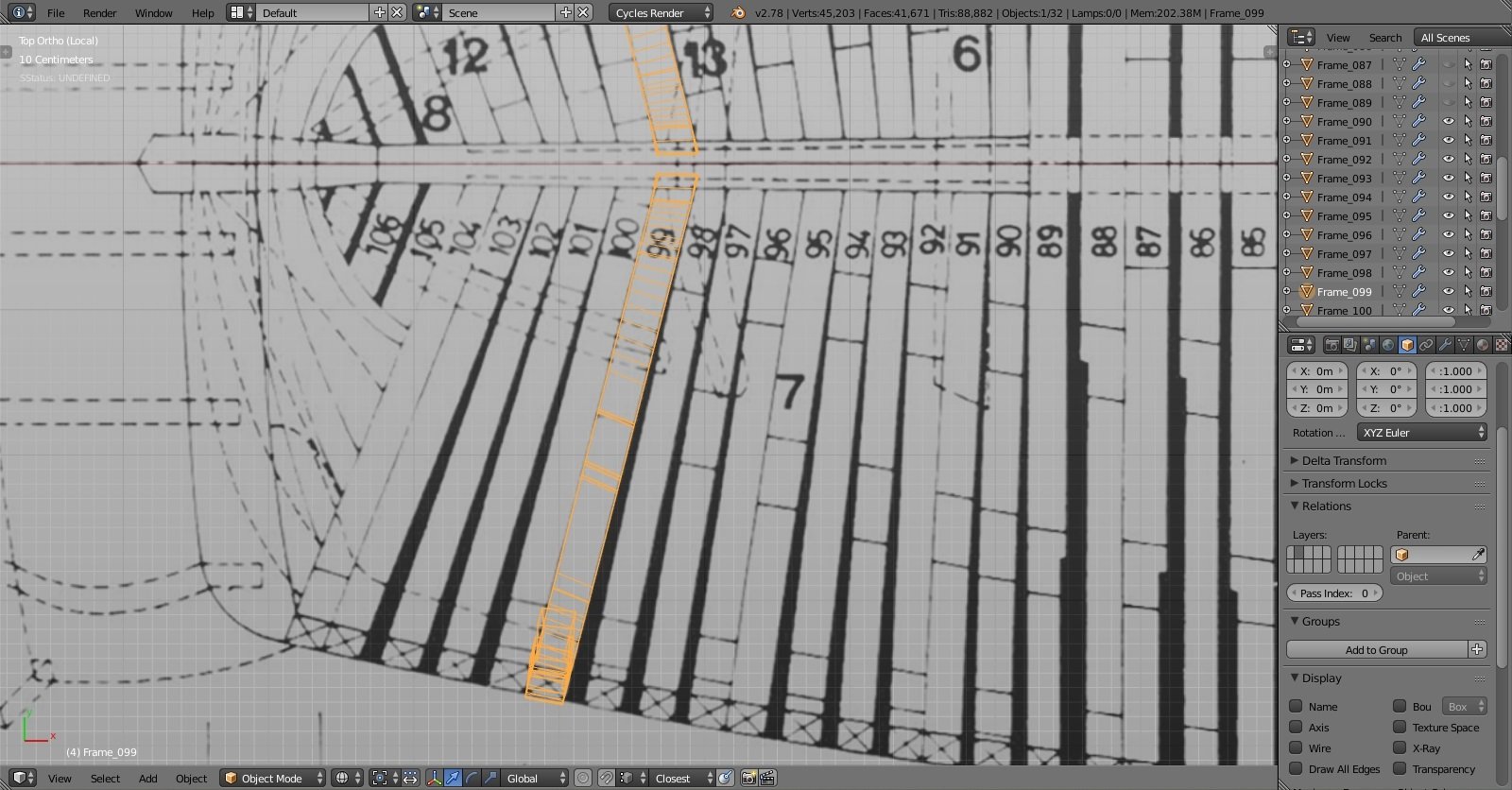
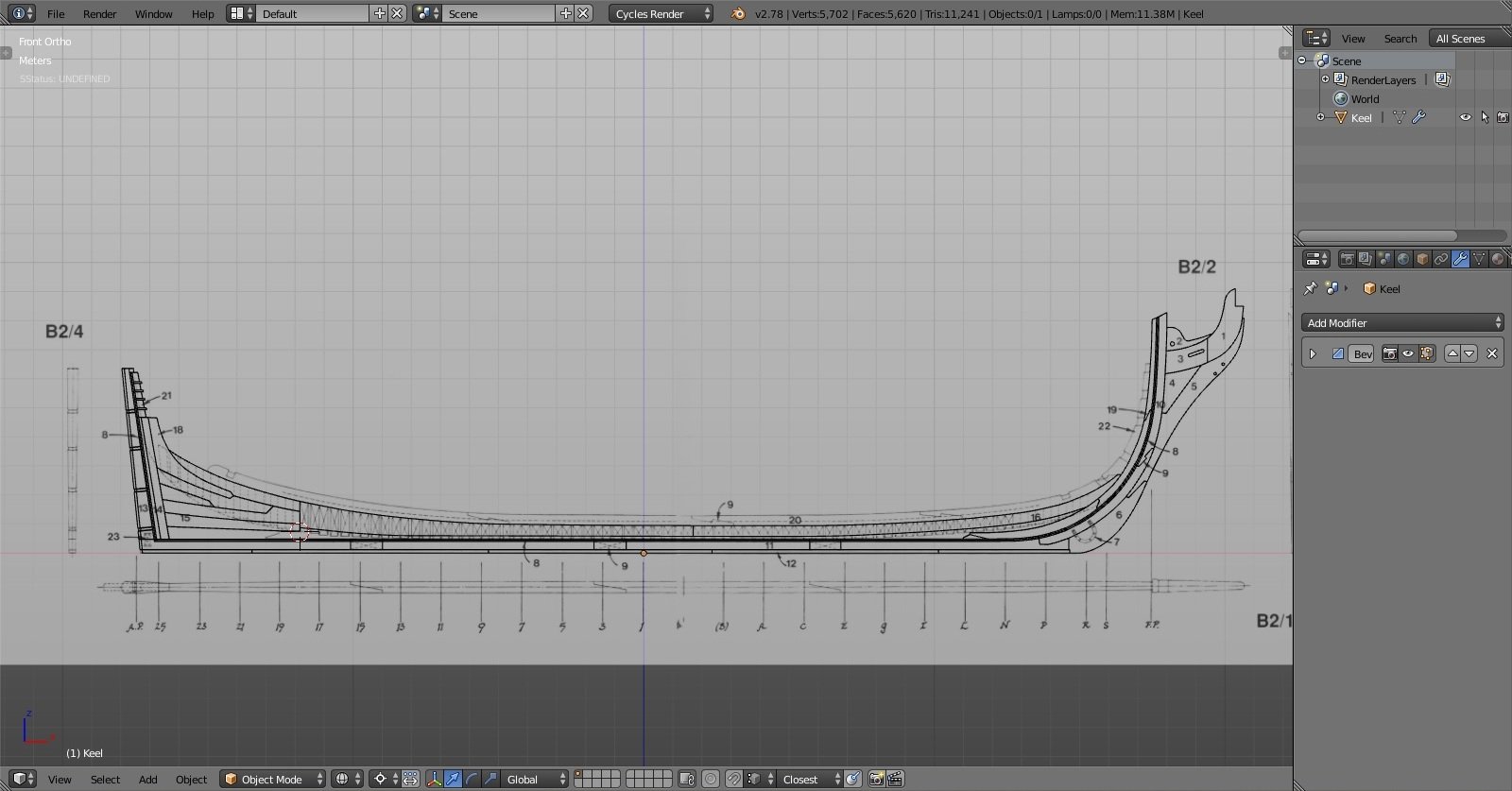
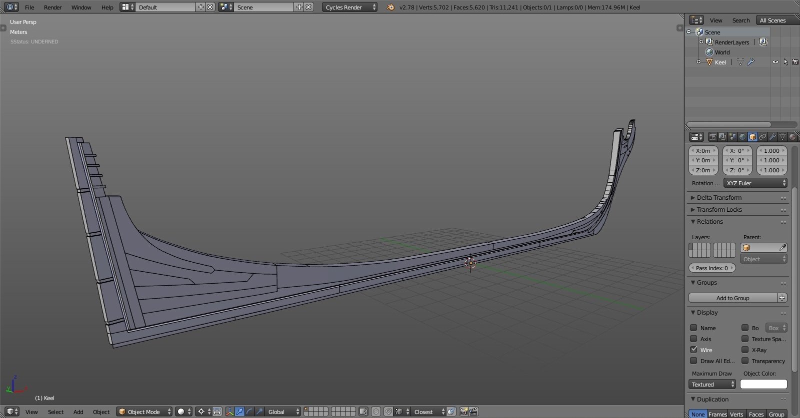
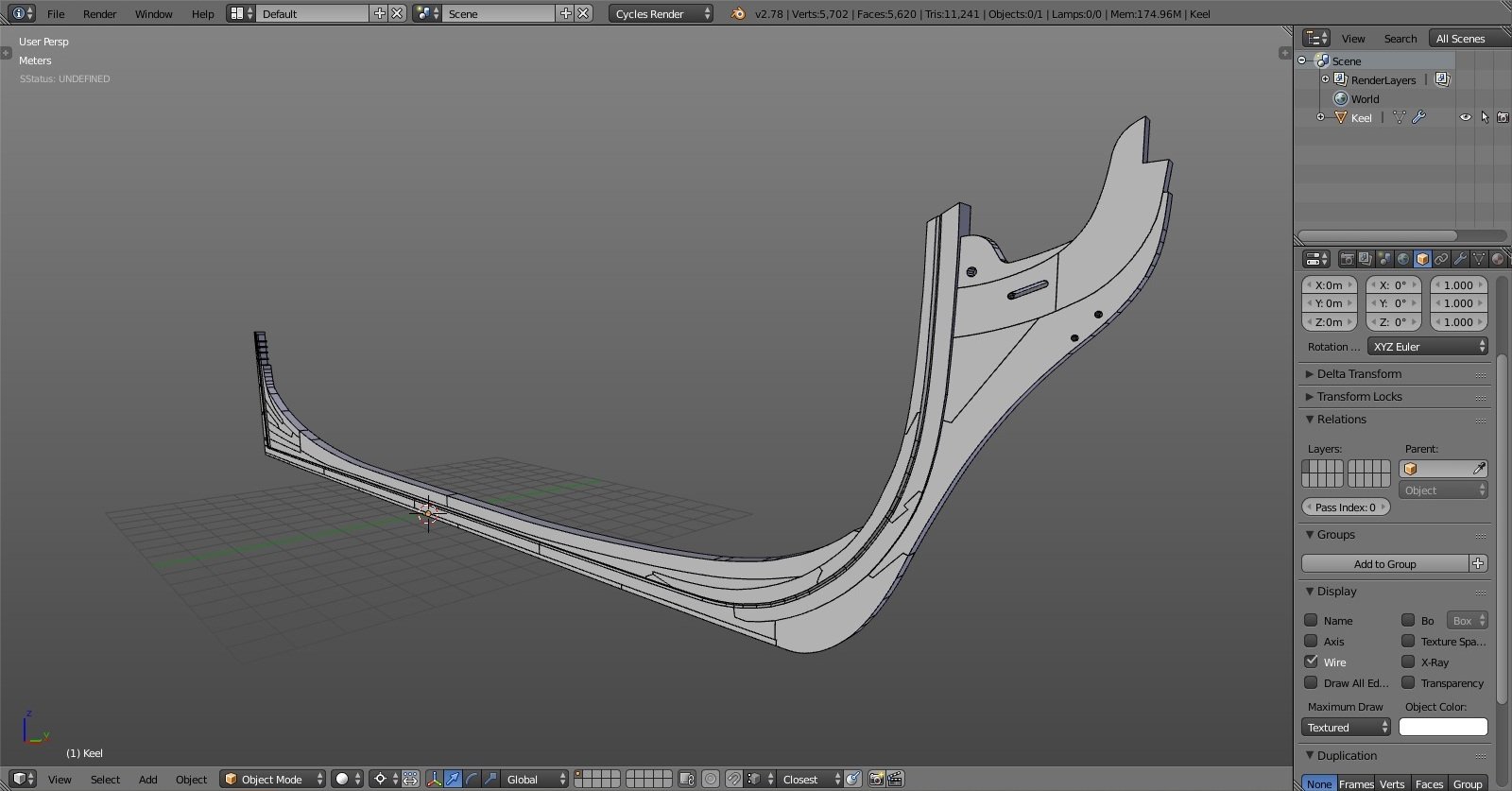
herask replied to herask's topic in CAD and 3D Modelling/Drafting Plans with Software
I begun with the keel assembly by tracing plan and making individual pieces. that was straightforward enough. although I see now I'll have to make some adjustments to the wood that holds that vertical pieces that hold transom (yeah, there'll be a lot of such wording until I pick up all of the naming, LOL) and cut wood above the rabbet for the frames. it is at this point I became aware I'll need to do some drafting to be able to create frames, as framing plans weren't aligned good enough and guesswork is something I would like to avoid, otherwise everything else won't fit inside the hull. I've read through drafting instructions manual found in article database and was again blown away by amount of work that goes into model ship building. (really, kudos to all of you for your patience and persistence!!) since I don't own CAD software I figured why not doing it right in Blender. at least I won't have to worry about aligning body, half breadth and profile plans on a 2d plane like in AutoCAD. in Blender it'll be done in 3D right away.