
JpR62
-
Posts
699 -
Joined
-
Last visited
1 Follower

Recent Profile Visitors
5,564 profile views
.thumb.jpg.0c4ba74a8c20632da6eafe3d432bde24.jpg)


-
 JpR62 reacted to a post in a topic:
Syren Ship Model Company News, Updates and Info.....(part 2)
JpR62 reacted to a post in a topic:
Syren Ship Model Company News, Updates and Info.....(part 2)
-
 JpR62 reacted to a post in a topic:
Syren Ship Model Company News, Updates and Info.....(part 2)
JpR62 reacted to a post in a topic:
Syren Ship Model Company News, Updates and Info.....(part 2)
-
JpR62 reacted to a post in a topic:
Syren Ship Model Company News, Updates and Info.....(part 2)
-
JpR62 reacted to a post in a topic:
Syren Ship Model Company News, Updates and Info.....(part 2)
-
 JpR62 reacted to a post in a topic:
L'Amarante by marsalv - 1:36 - POF
JpR62 reacted to a post in a topic:
L'Amarante by marsalv - 1:36 - POF
-
JpR62 reacted to a post in a topic:
Carving from Belgorod
-
JpR62 reacted to a post in a topic:
L'Artésien 1764 by Cpt.Barbossa - 1:48 - 64-gun ship from plans by Jacques Fichant
-
JpR62 reacted to a post in a topic:
L'Artésien 1764 by Cpt.Barbossa - 1:48 - 64-gun ship from plans by Jacques Fichant
-
thibaultron reacted to a post in a topic:
Dust collector jig for sanding drum....
-

Dust collector jig for sanding drum....
JpR62 replied to Sterling59's topic in Modeling tools and Workshop Equipment
Hello Dale, Oliver1973 posted a link to an adapter for the Proxxon DH 40 thicknesser. I don't know if this adapter is what you're looking for... https://modelshipworld.com/topic/36705-suction-adapter-for-the-proxxon-dh40-for-download/#comment-1048690 Jean-Paul -
Thank you for the explanations. In a similar note, last week I came across a video by the 'Association Modélisme Ferroviaire Alsace' (AMFA68) explaining how to create figurines from a JPEG photo. Here is the link to the video. https://www.youtube.com/watch?v=N2qnYzfCwiQ&t=857s The video is on YouTube and is in French. But all you have to do is activate the subtitles (automatically generated in French) and then activate the automatic English translation of these subtitles. Basically, the process is as follows. Starting with a photo of a person (you can even use AI to generate the photo in Photoshop!), you cut it out using Photoshop to remove the background around the subject. This image is then imported into the 'studio.tripod3d.ai' program (the free version limits the program to generating 3 figures per day). This program converts the jpeg file into a 3D stl file. You can then retrieve the STL file in Fusion360 to scale it. All that remains is to print the figurine... I was impressed by how easy the process was.
-
FrankWouts reacted to a post in a topic:
Duchess of Kingston 1778 by Rustyj - FINISHED - Vanguard Models - 1:64 - Royal Yacht
-
Canute reacted to a post in a topic:
Syren Ship Model Company News, Updates and Info.....(part 2)
-
Canute reacted to a post in a topic:
Syren Ship Model Company News, Updates and Info.....(part 2)
-
Ryland Craze reacted to a post in a topic:
Syren Ship Model Company News, Updates and Info.....(part 2)
-
Ryland Craze reacted to a post in a topic:
Syren Ship Model Company News, Updates and Info.....(part 2)
-
mtaylor reacted to a post in a topic:
Syren Ship Model Company News, Updates and Info.....(part 2)
-
Nirvana reacted to a post in a topic:
Syren Ship Model Company News, Updates and Info.....(part 2)
-
Thanks for the clear and precise answer, and thanks again for the tutorial. There's often a tendency to want to complicate things when, more often than not, it's the simplest methods that give the best results !
-
Many thanks for these explanations and this superb step-by-step guide. A quick question about cyano glue. Can I use any brand or is there a specific brand that prevents the thread discoloration? In a nutshell: is it simply cleaning with your finger that prevents discoloration, or does the brand of CA also play a role? These blocks are really superb! Thank you for all your hard work !
-
What a magnificent model this Winchelsea is! The choice of wood species is absolutely perfect, and what can I say about the quality of the work! Thank you for giving us the opportunity to follow this superb work.
- 399 replies
-
- 2
-
-
- winchelsea
- Syren Ship Model Company
- (and 1 more)
-
Congratulations on this beautifully detailed and perfectly crafted model. Many thanks for sharing all the steps and research. It was a real pleasure.
-
HM Cutter Cheerful 1806 by JpR62 - 1:48 scale
JpR62 replied to JpR62's topic in - Build logs for subjects built 1801 - 1850
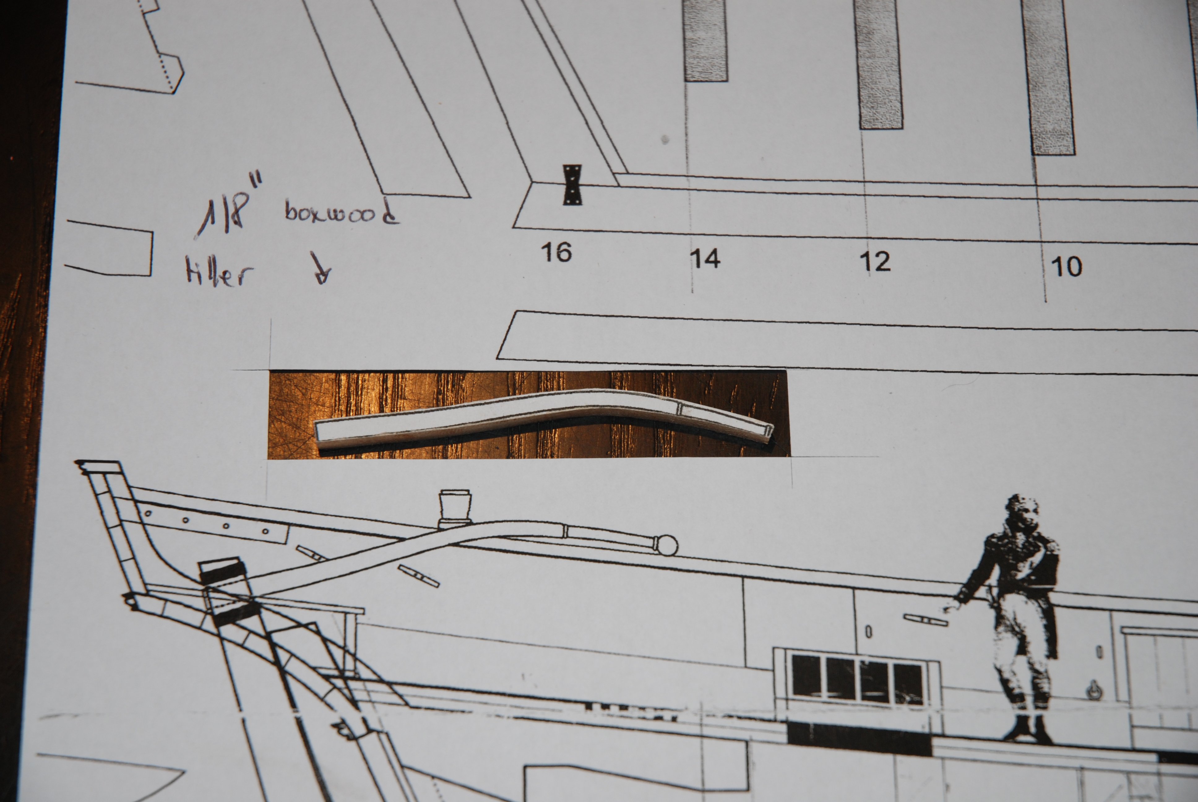
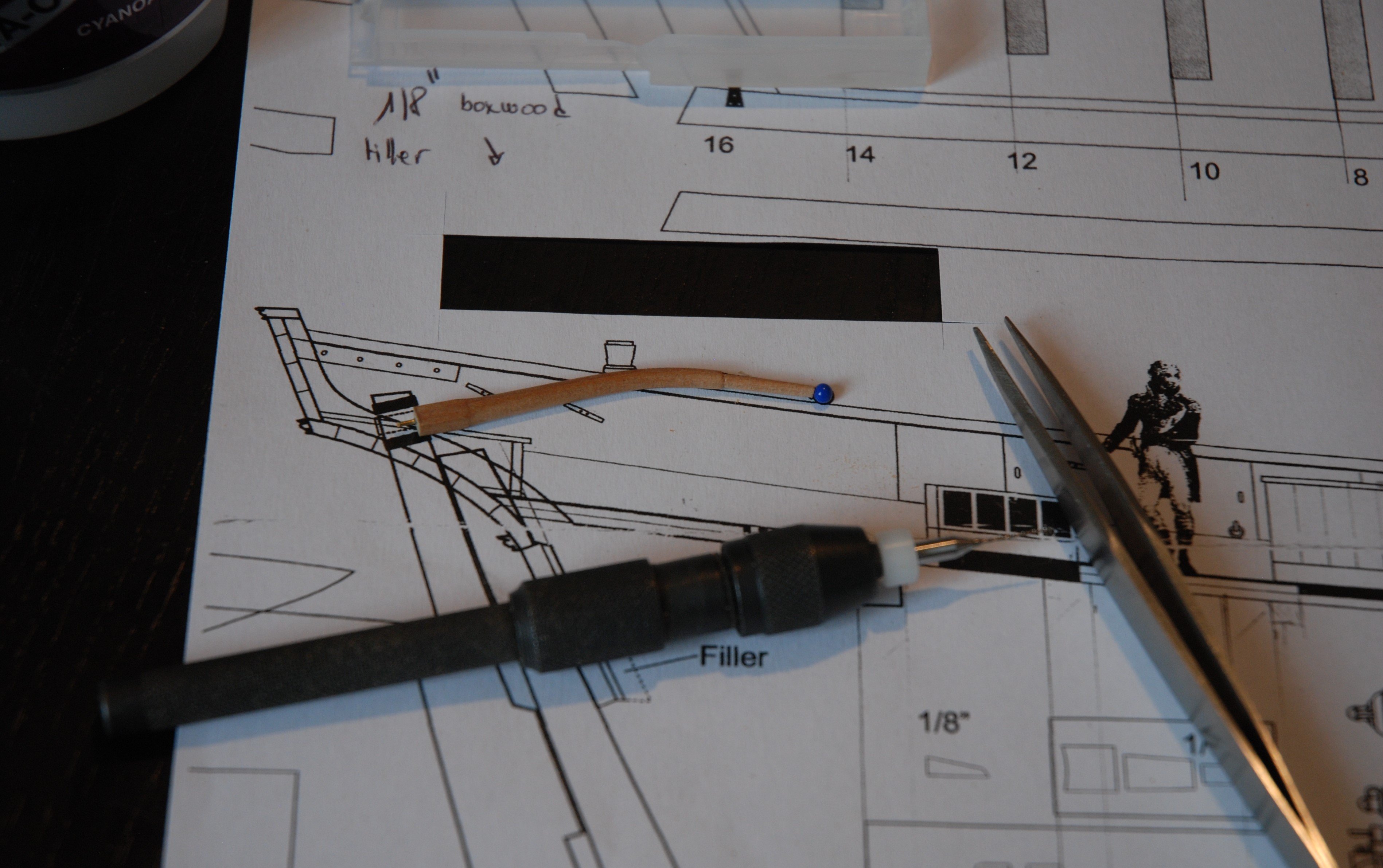
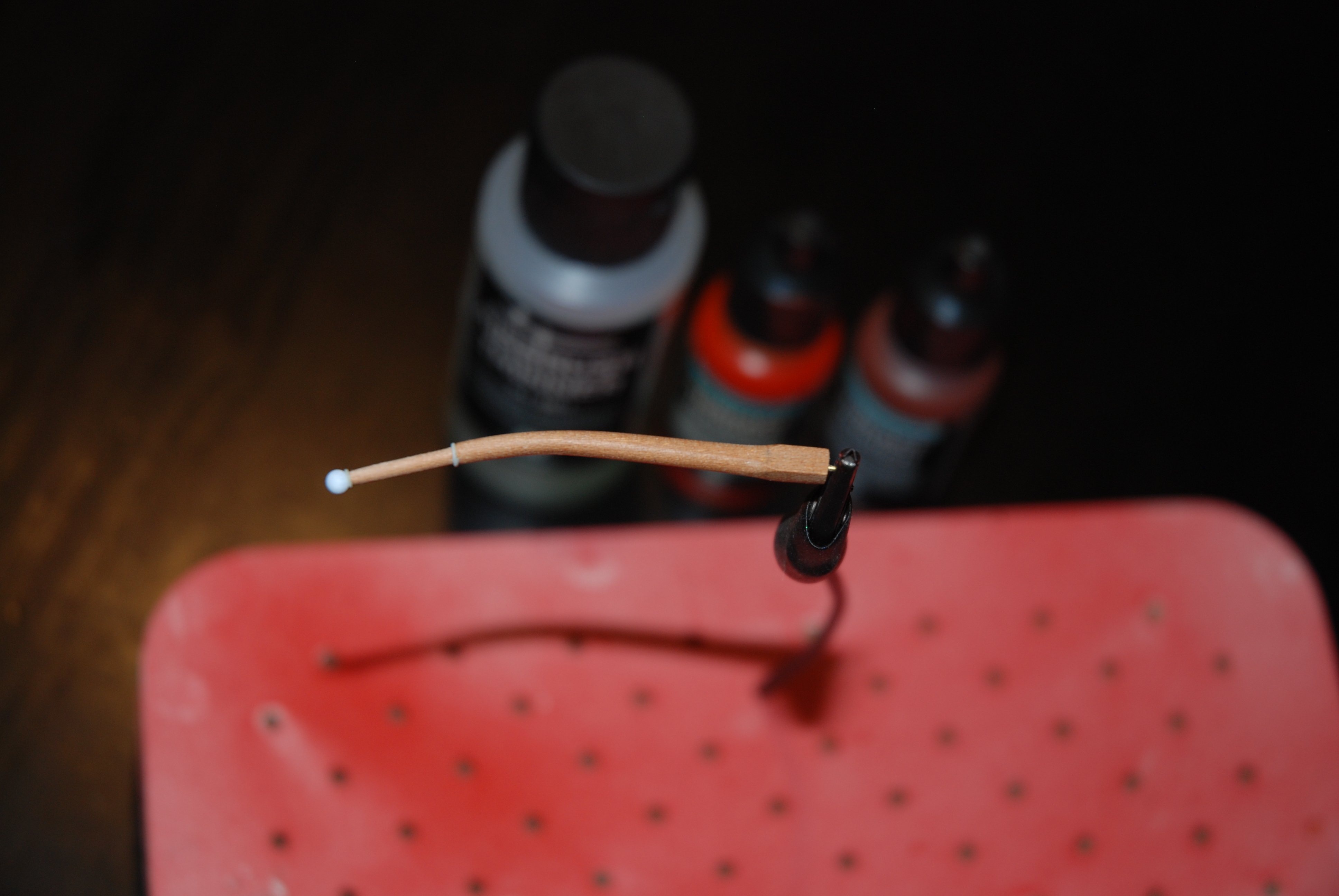
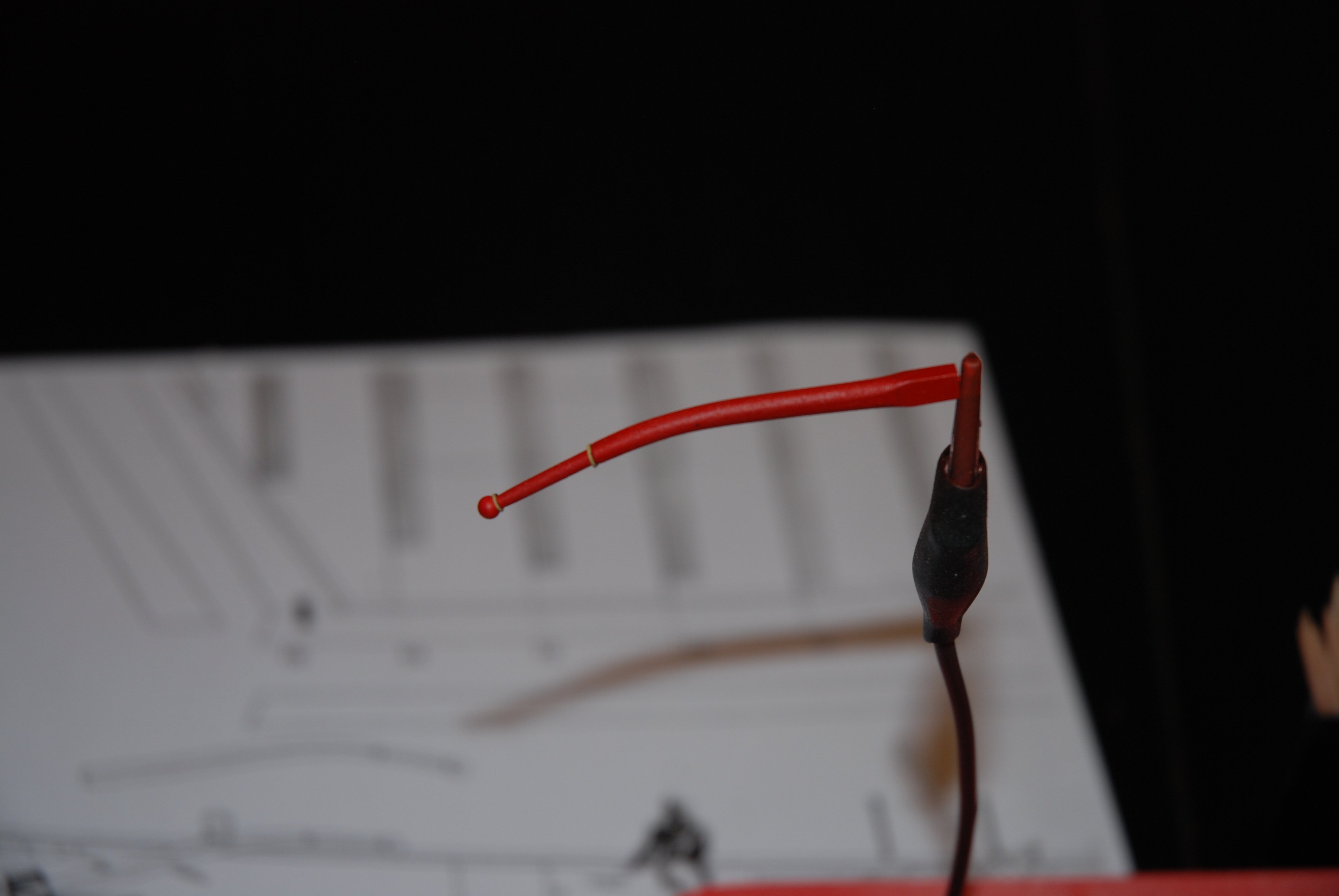
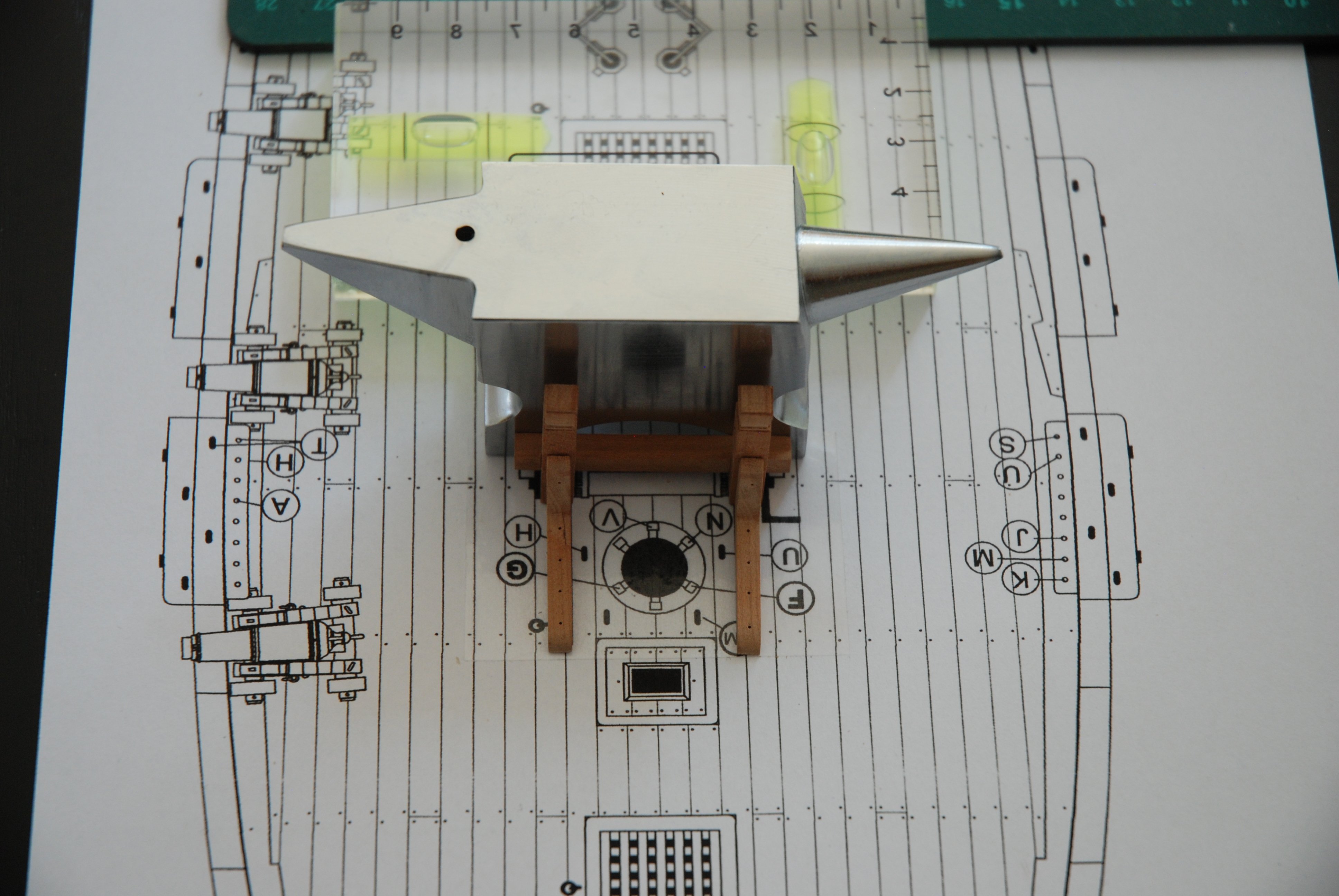
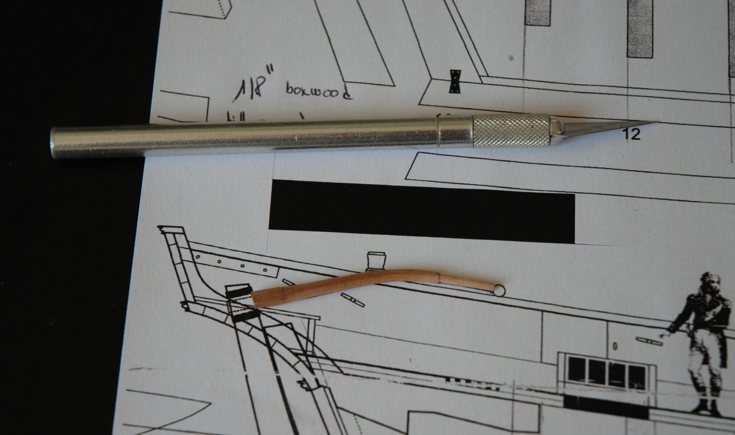
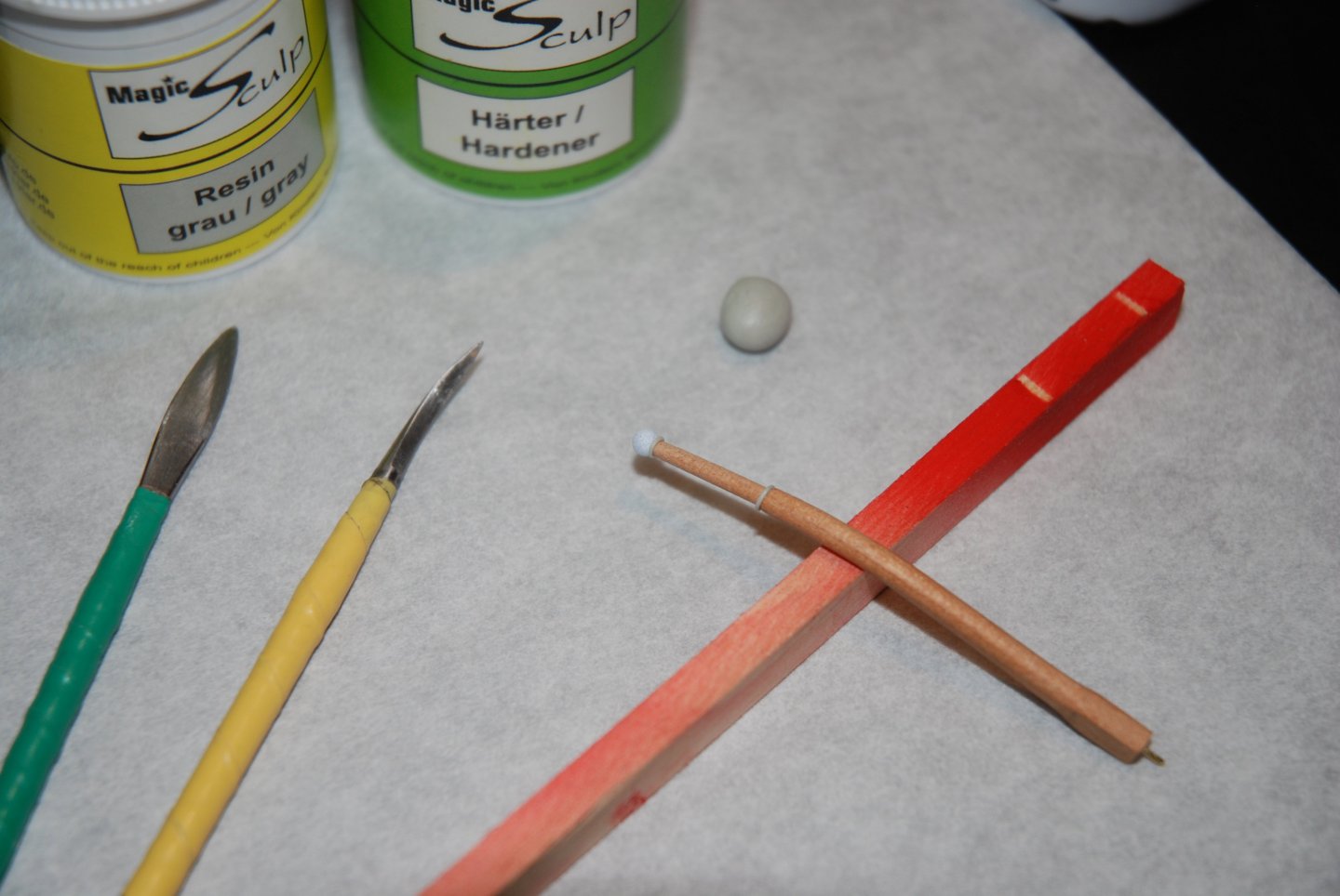
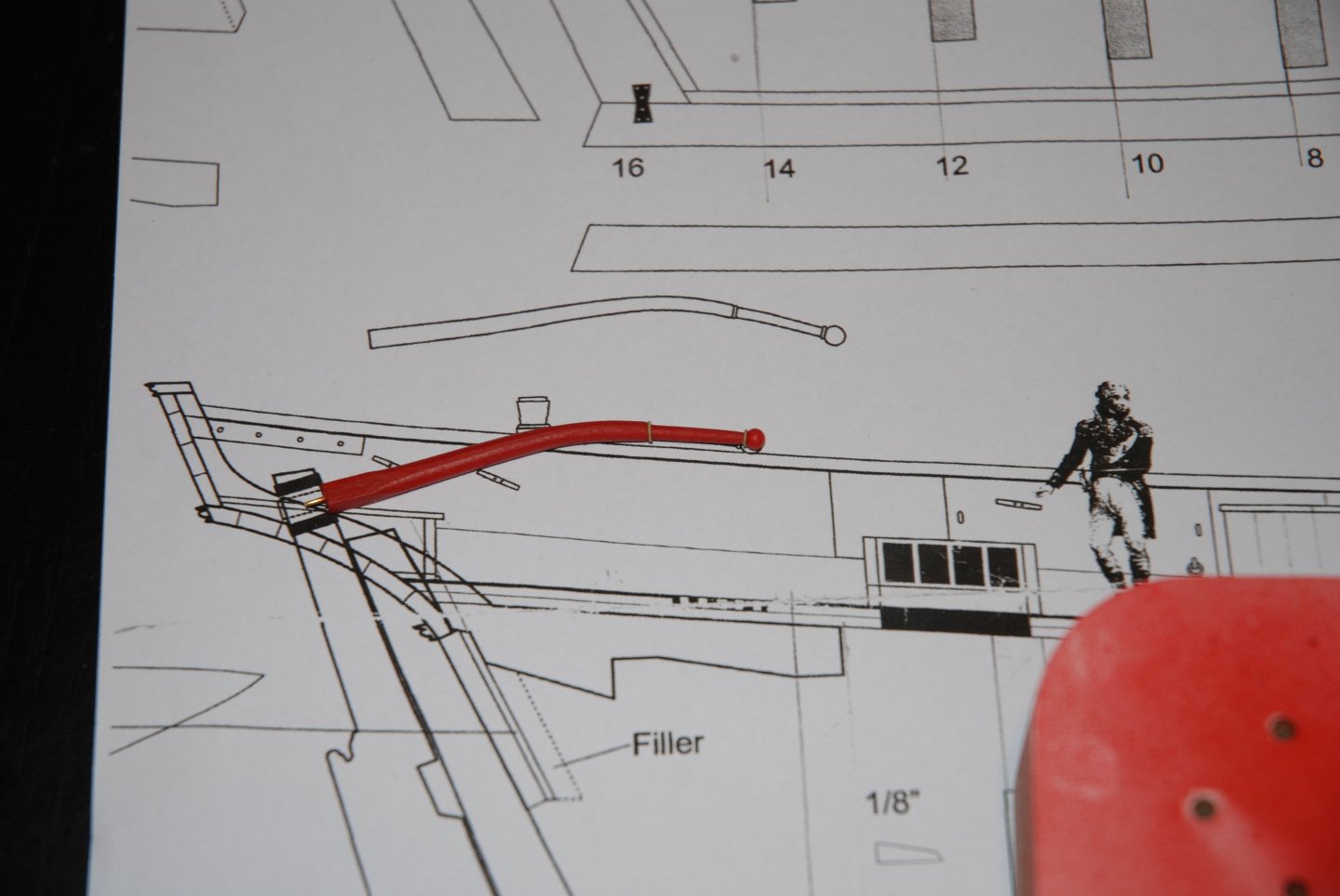
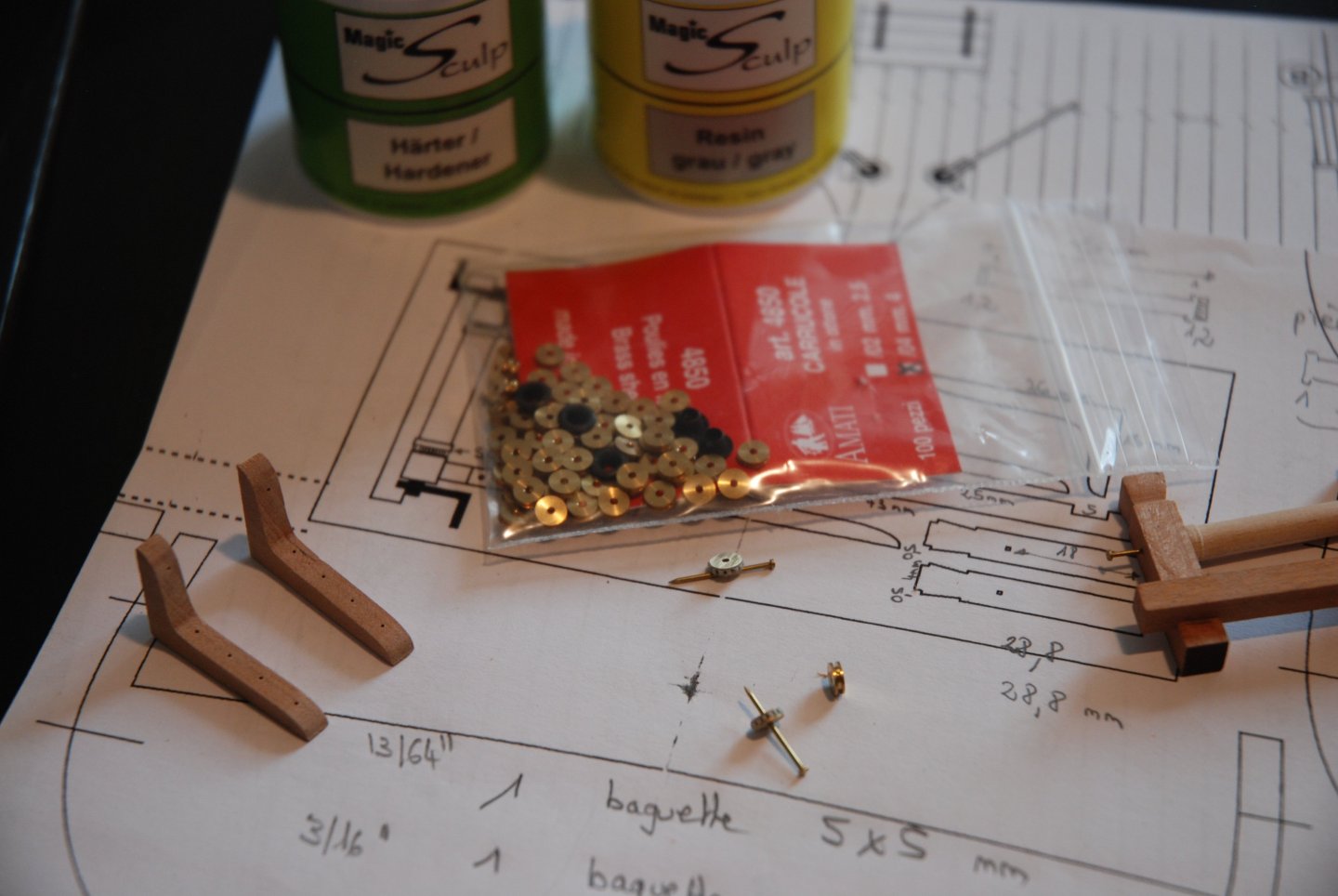
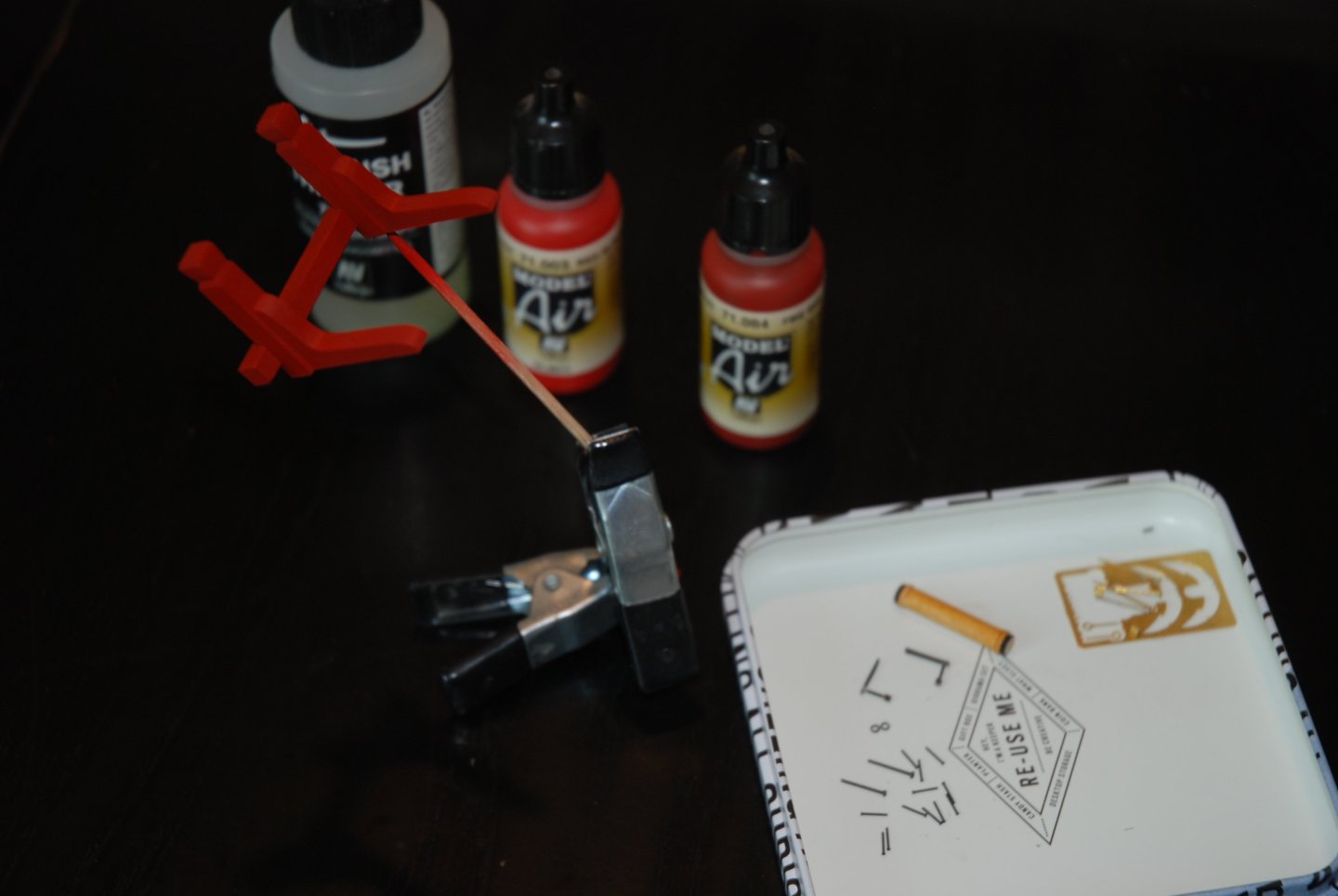
Thank you Glenn and Al for your kind remarks and thank you to all the 'Likes'. The tiller Not being confident in my ability to make the end of the tiller with a perfect sphere, I decided to compose my tiller by assembling several elements. It consists of three distinct parts, each made from a different material: the main body of the tiller will be carved from a 1/8” thick piece of cherry wood, the sphere at the end of the tiller comes from a glass-headed pin and the fine connections (mouldings) between the various elements are sculpted using two-component resin. So I start by cutting the main body from a 1/8” cherry board. I sculpt it to its proper shape using files and a #11 blade After piercing the end of the piece, I insert the pin shaft of the glass-headed pin (cut to a length of a few millimeters). I then mask the wooden body of the tiller and spray the pinhead with primer (Revell basic spray) to facilitate final coloring. I could have used brass wire to make the connectors (mouldings), but I preferred to use two-component putty because it's so much simpler: there's no need to glue, as the putty sticks to the wood and pinhead all by itself, and it's also very easy to make a thin 'wire' of the right cross-section by simply rolling a small ball of putty with a finger. What's more, once the putty 'wire' has been wrapped around the tiller, the joint is smoothed with a moistened brush and is perfectly invisible... The tiller is then painted red using my airbrush. A final check on the plan and the tiller is ready to be installed. I can move on to building the pumps.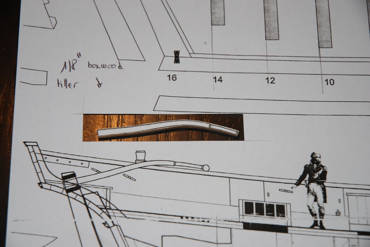


-
This Winchelsea is a magnificent ship model. Many thanks for your many posts, always very detailed and above all very instructive. It's been a real pleasure to follow this superb work.
- 840 replies
-
- 3
-
-
- winchelsea
- Syren Ship Model Company
- (and 1 more)
-
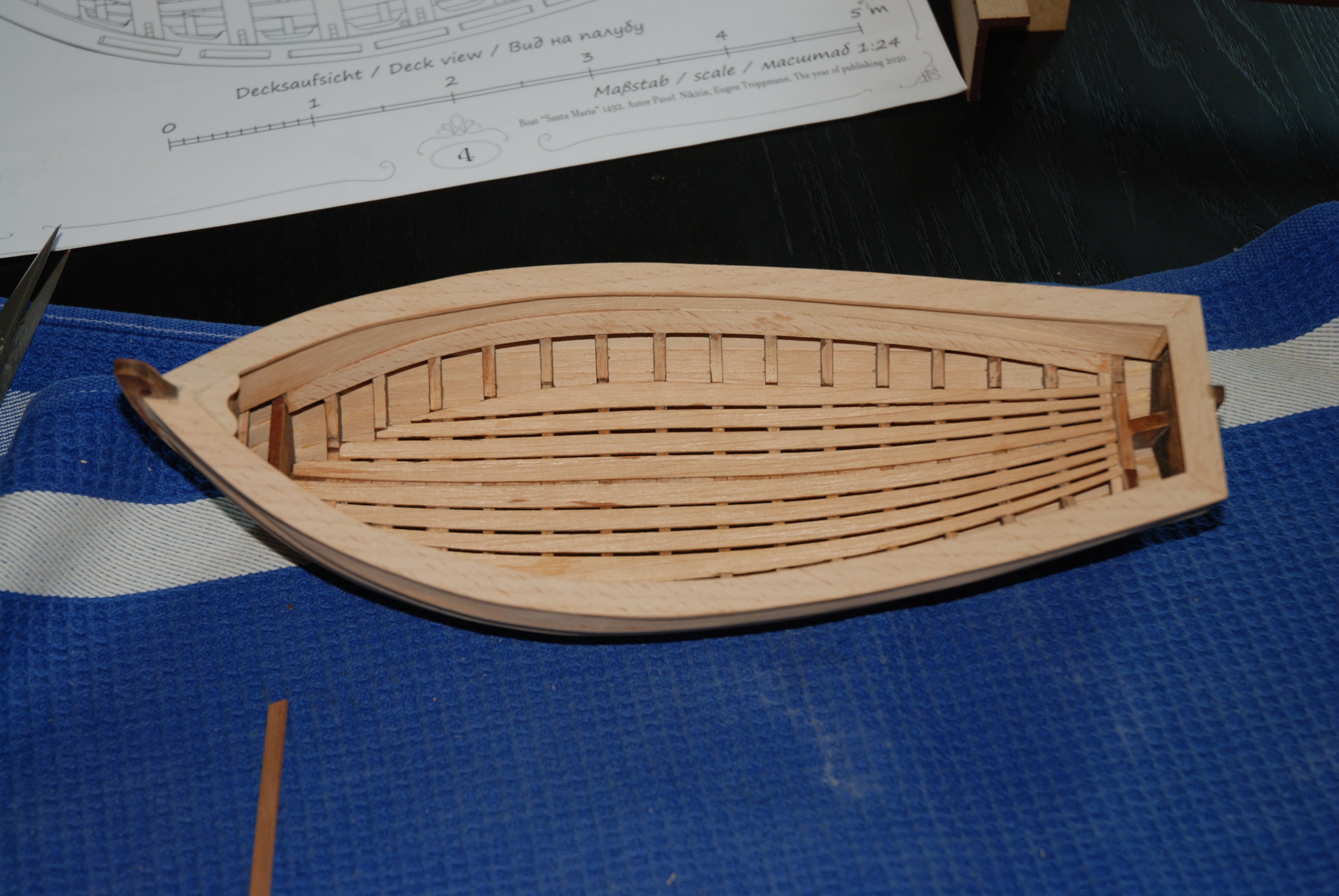
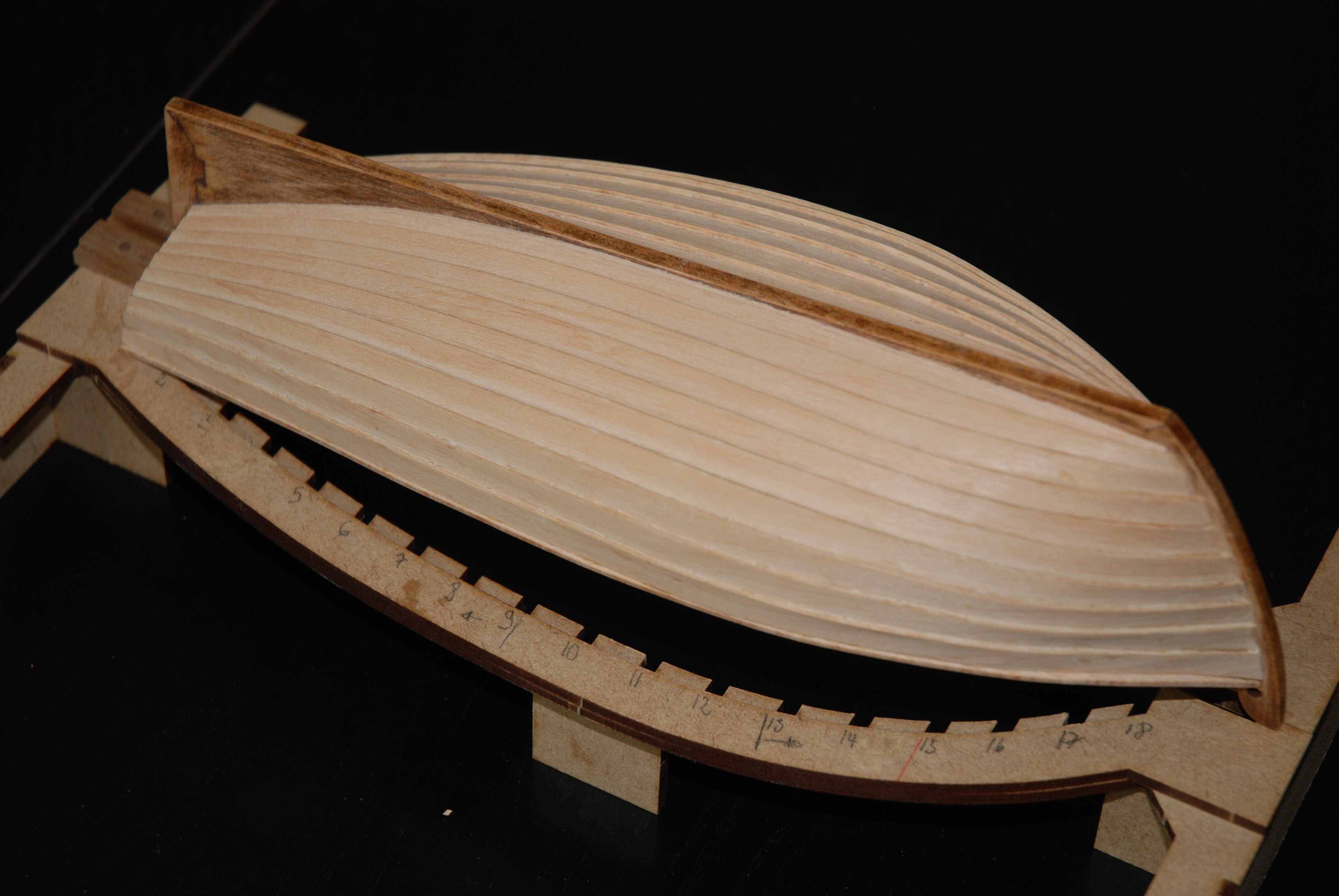
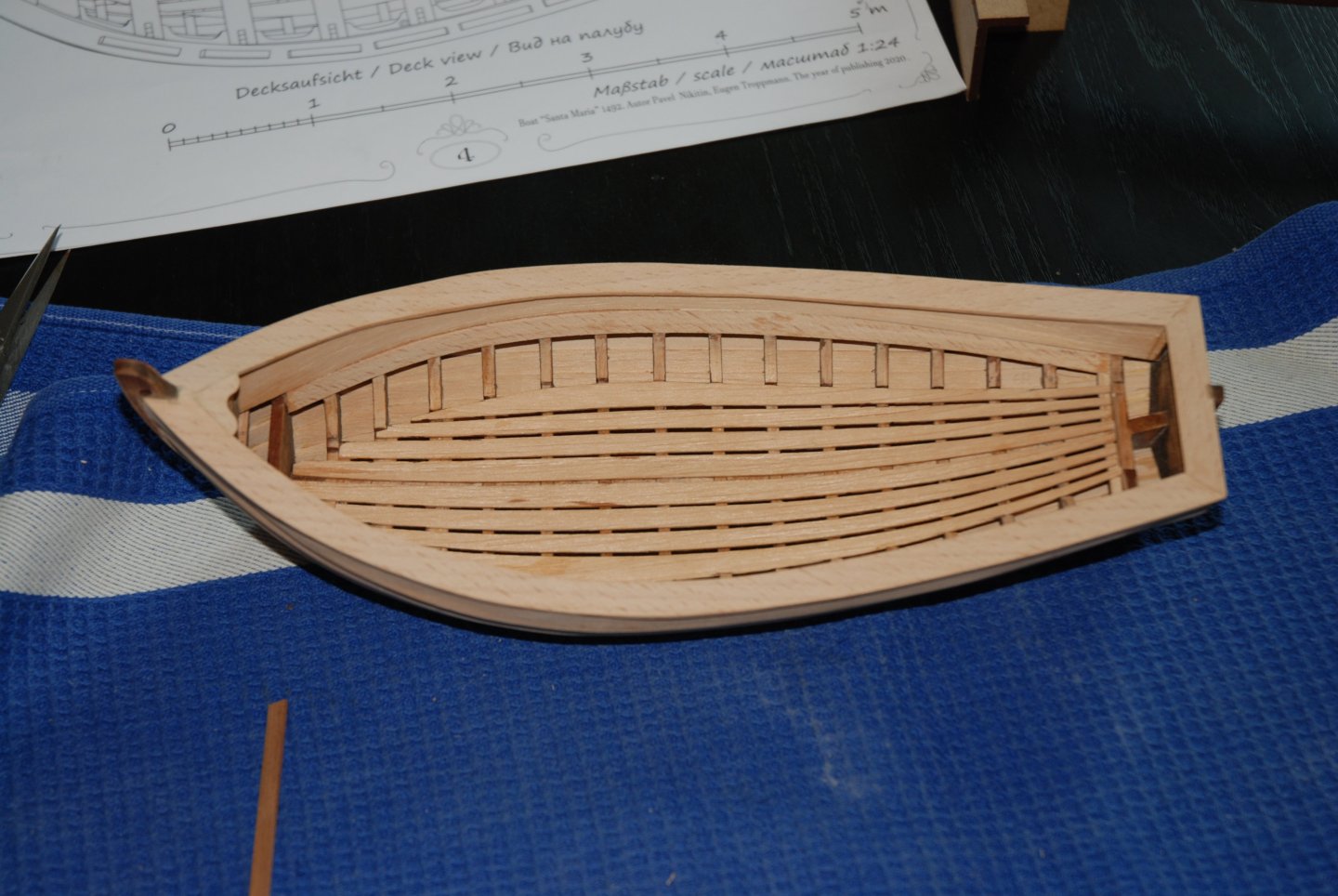
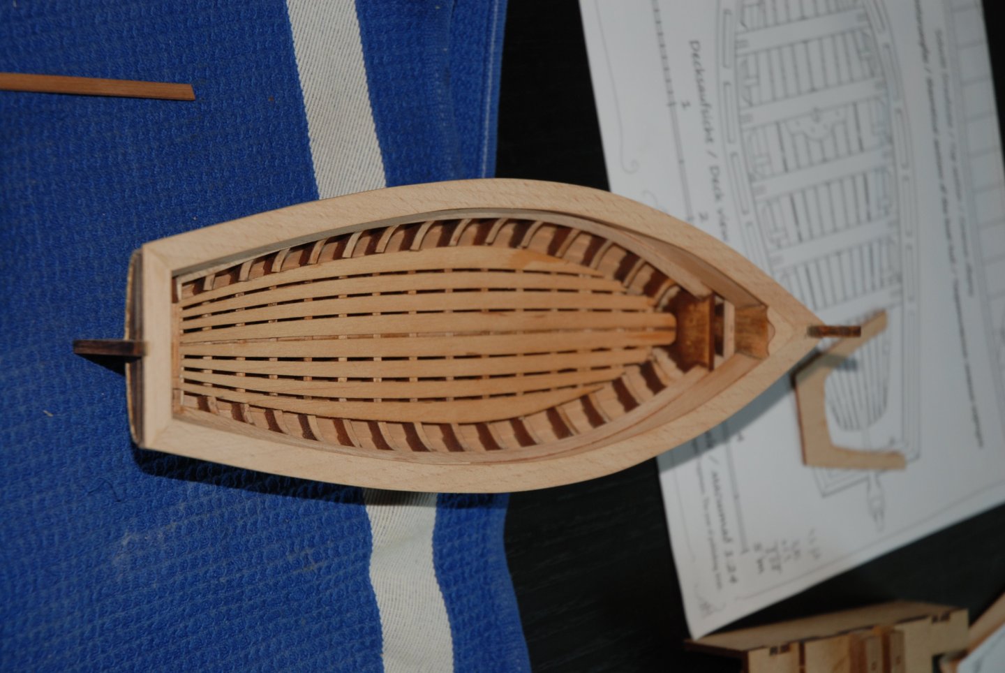
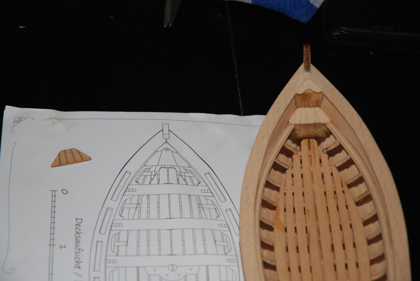
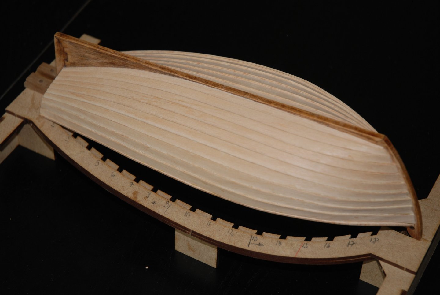
Thank you to all the 'Likes'. The gunwale has been installed. I started by fitting the aft section so I can adjust the length of the gunwale to port and starboard. There's just one small adjustment to make so that the parts fit perfectly on the stem. For the small deck at the bow, I decided to replace the part proposed in the kit with one made from the remains of the laser-cut planking board. It respects the plan better than the original part, and it's not at all complicated to make. Next step: installation of the thwarts

- 22 replies
-
- 6
-
-
- ships boat
- Korabel
- (and 1 more)
-
HM Cutter Cheerful 1806 by JpR62 - 1:48 scale
JpR62 replied to JpR62's topic in - Build logs for subjects built 1801 - 1850
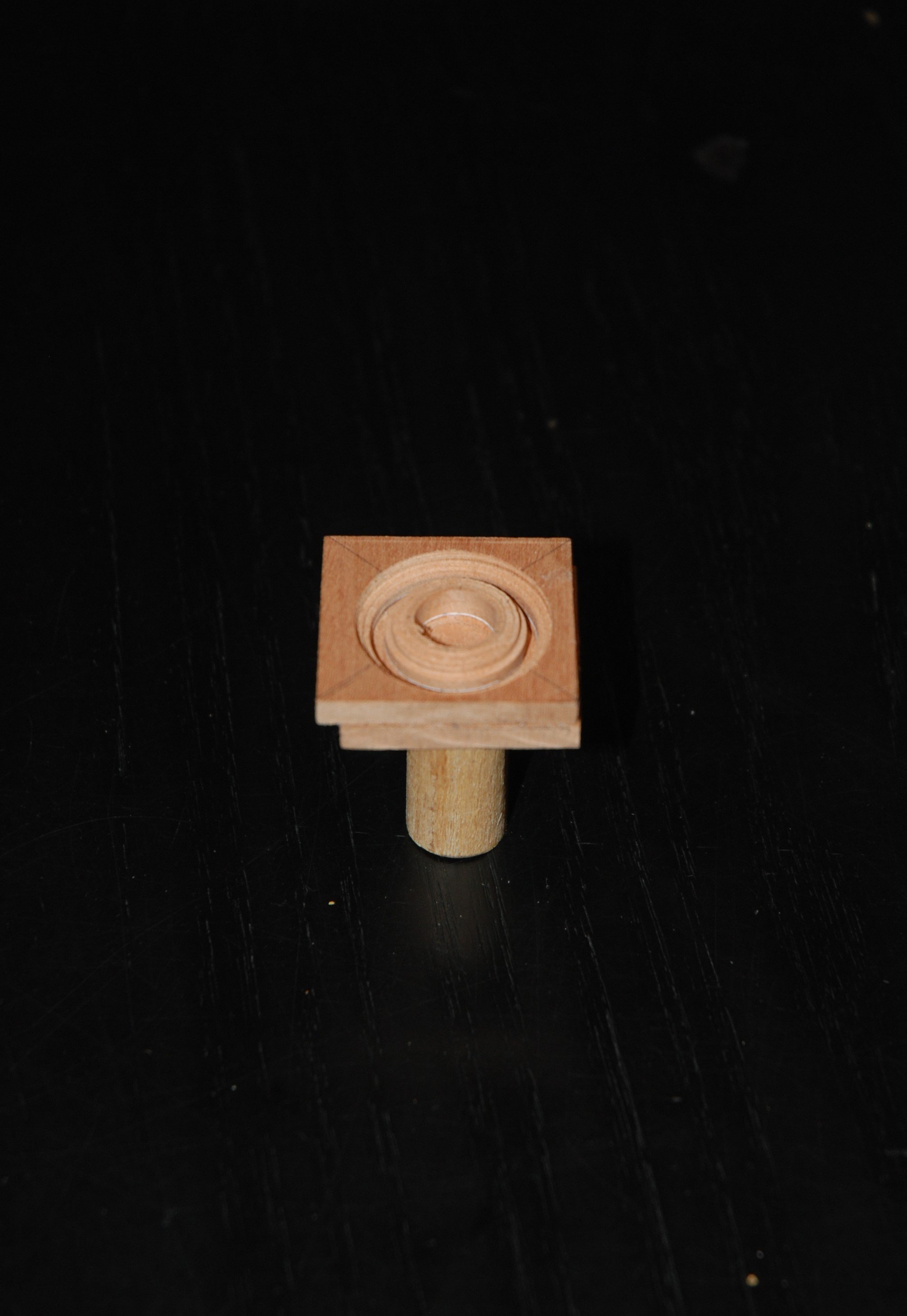
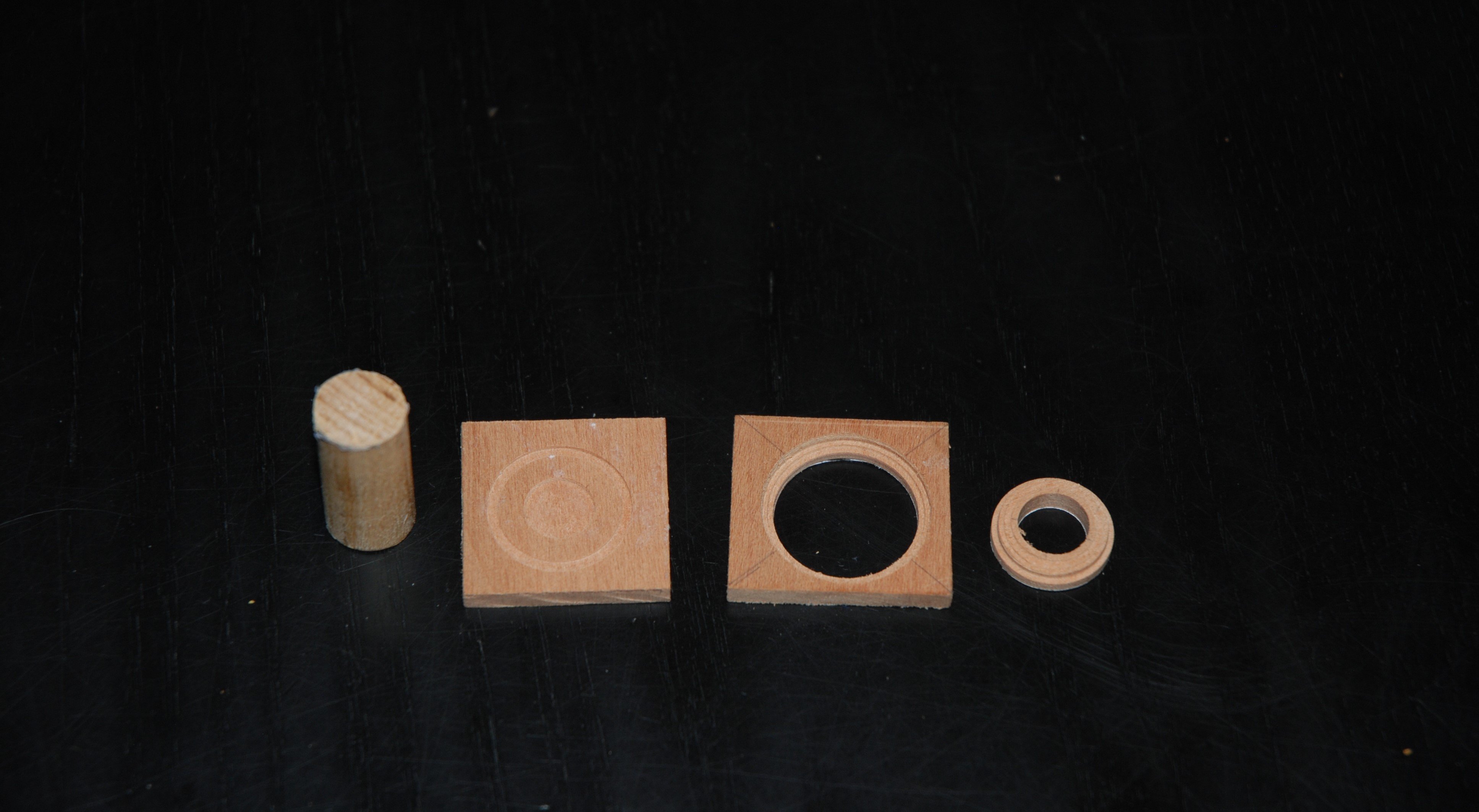
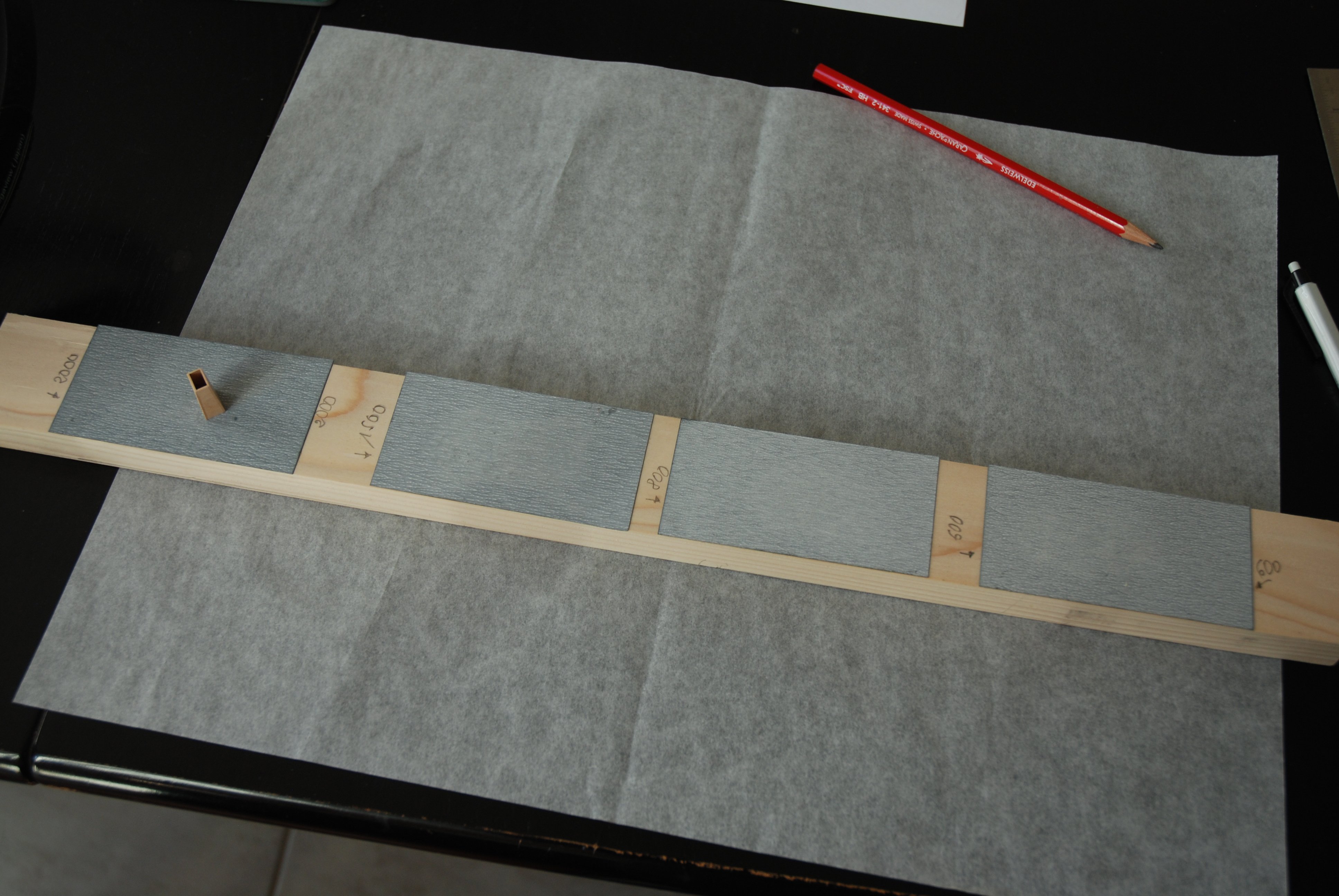
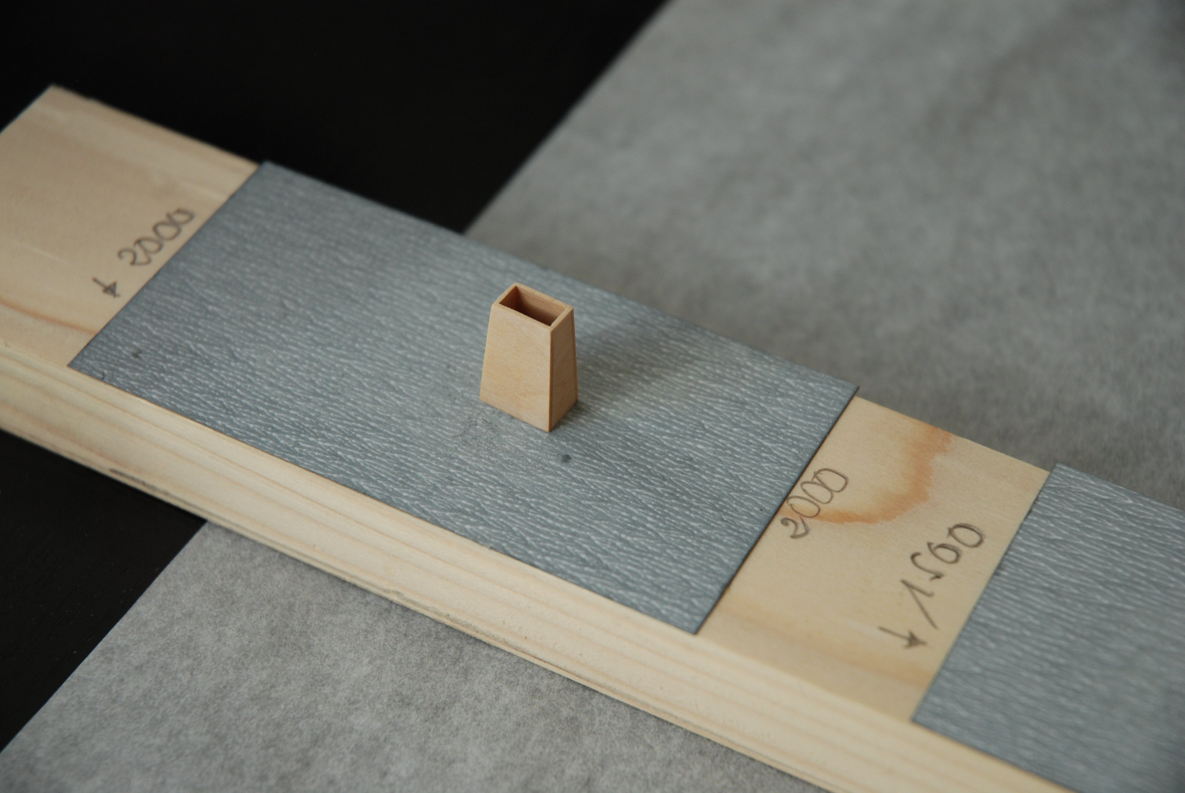
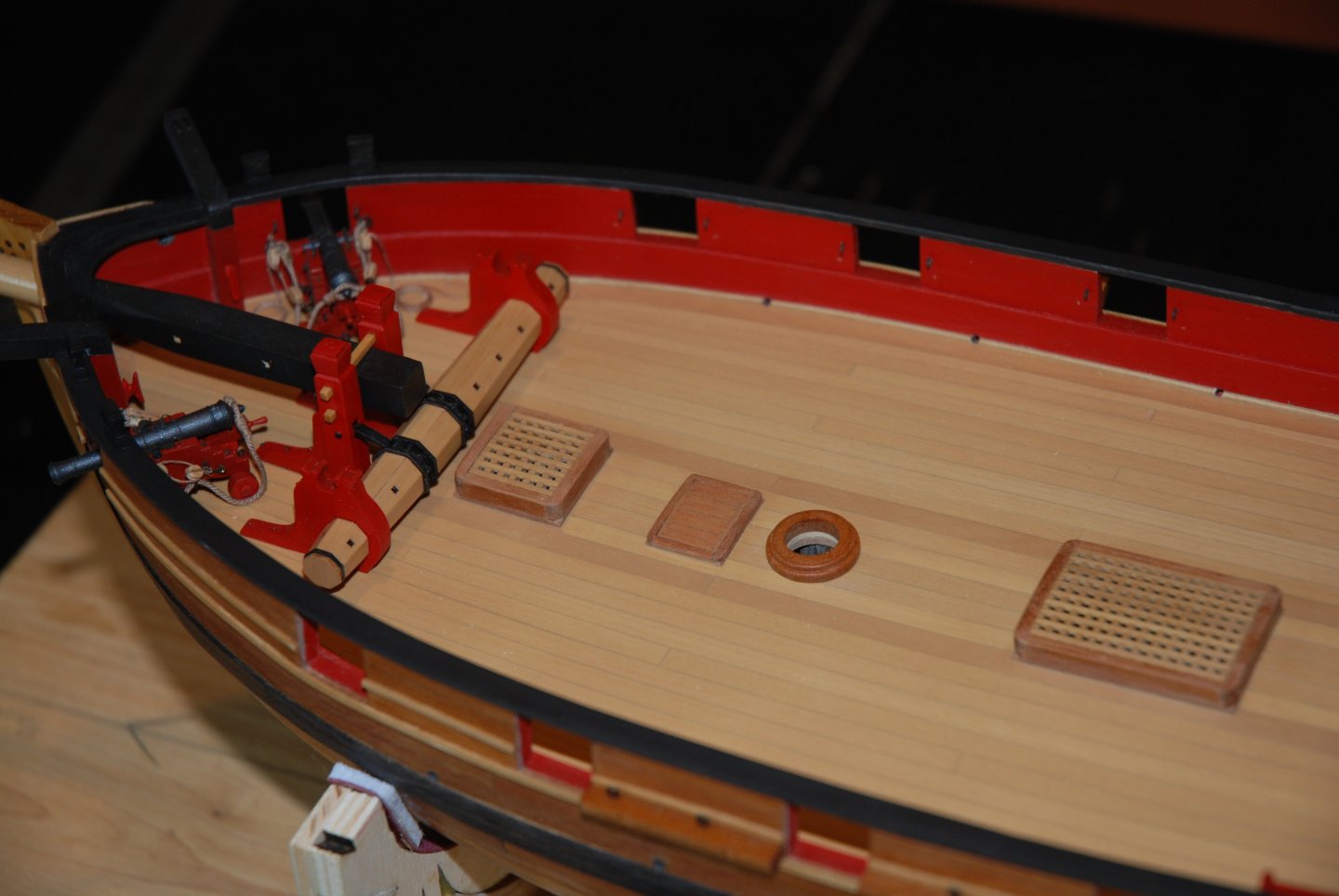
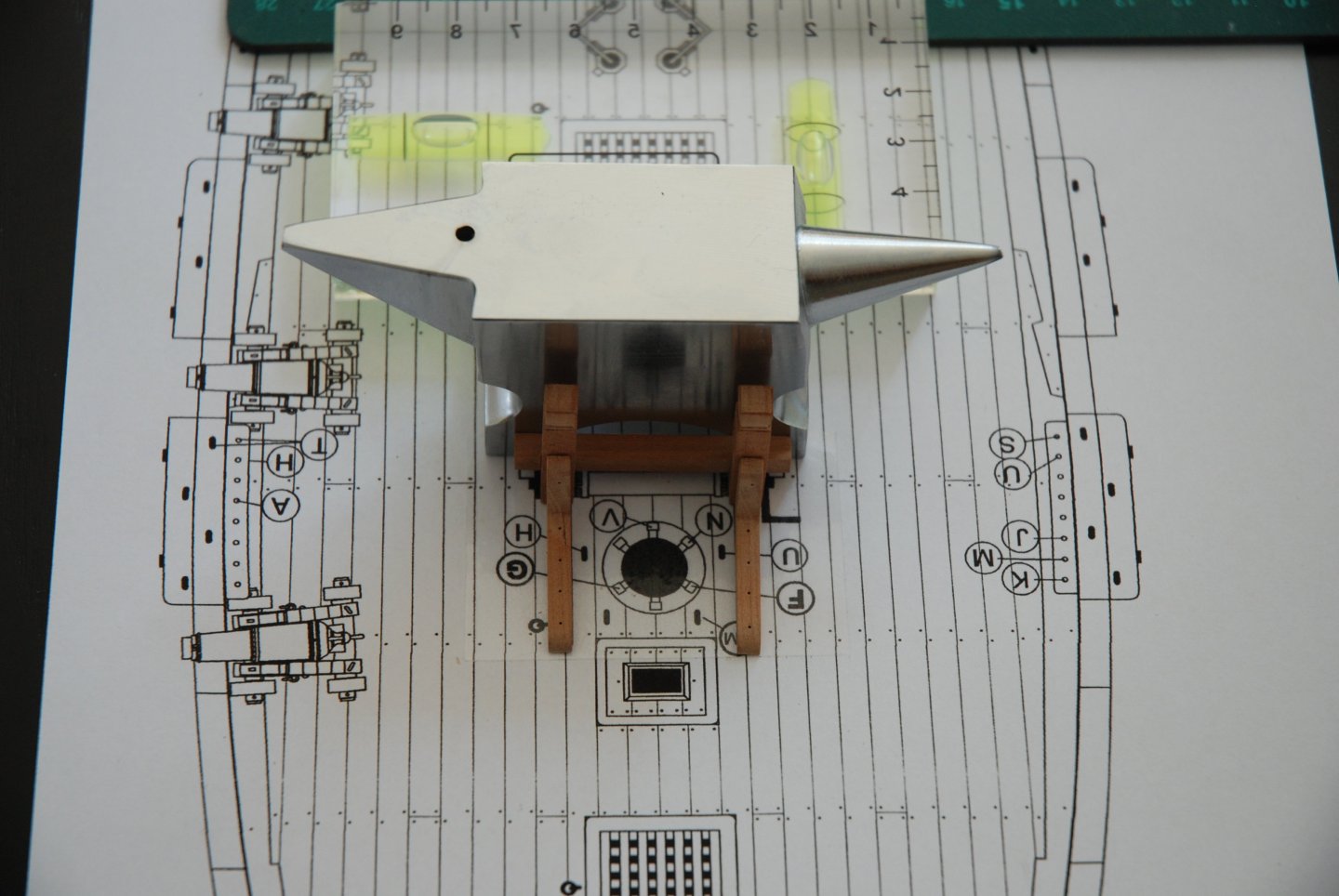
Thank you to all the 'Likes'. My work on the various elements on the Cheerful's deck continues with the construction of two additional pieces: the galley stack and the mast coat. The mast coat I used my Proxxon MF 70 mini milling machine again, this time with its dividing head. First, I glued a piece of 'martyr' wood to a short section of a wooden rod. Then I used double-sided scotch to glue the piece of wood from which I'll cut the mast coat. Then all you have to do is 'play' with the milling machine and its dividing head. We disassemble the various components and refine the result with a file and sandpaper. This dividing head is really easy to use and produces a perfectly round part. The galley stack Measurements are taken from the plan. The only thing I paid attention to was the final sanding. As this piece is supposed to be made of metal, it has to be perfectly smooth, so that you can no longer see the wood grain. So I sanded it several times, each time moving on to a finer grain. Fortunately, I had Tamiya sanding sheets in stock, with grit up to 2000. So I cut small rectangles of different grits and glued them to a piece of wood to create a perfectly flat surface. To be continued


-
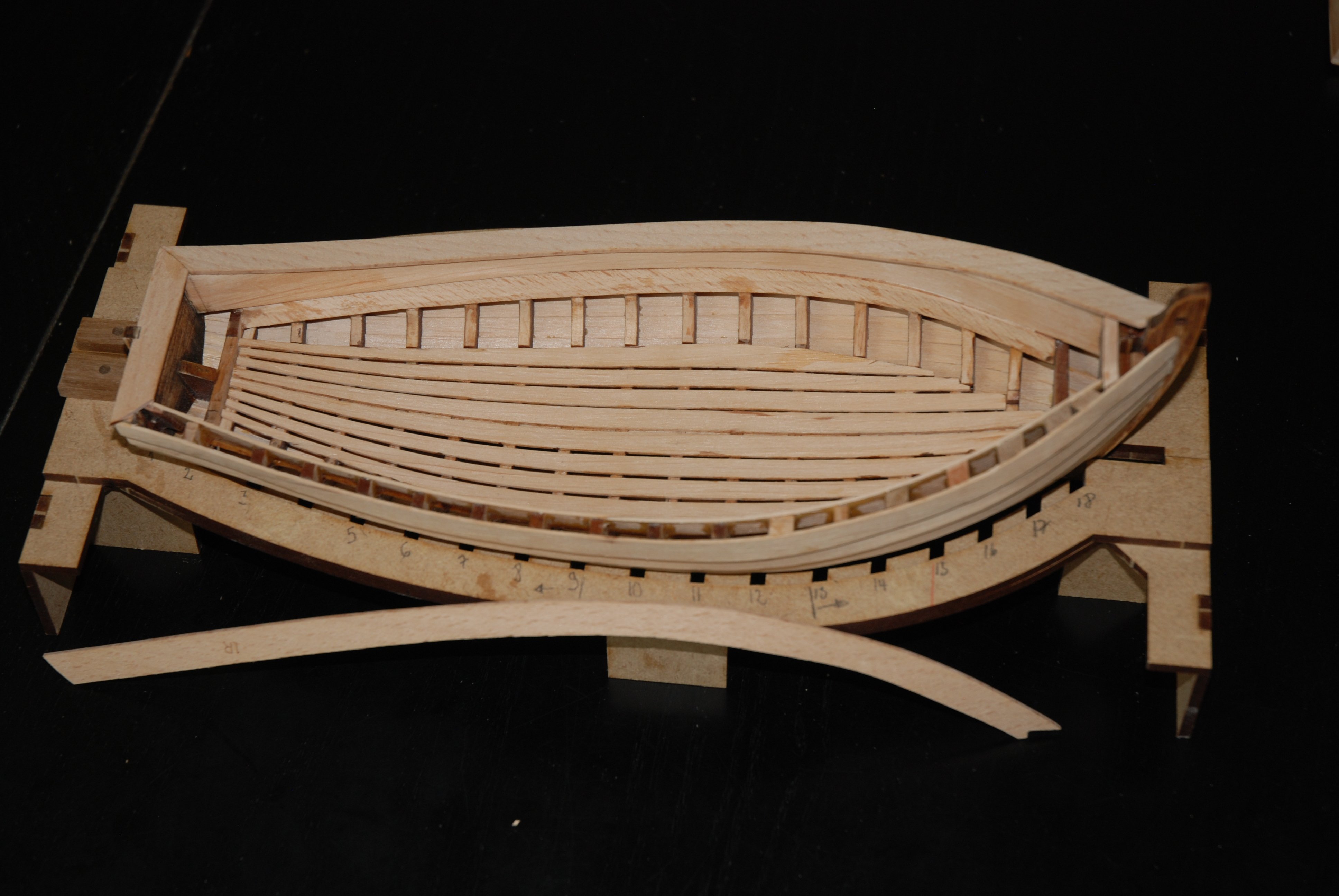
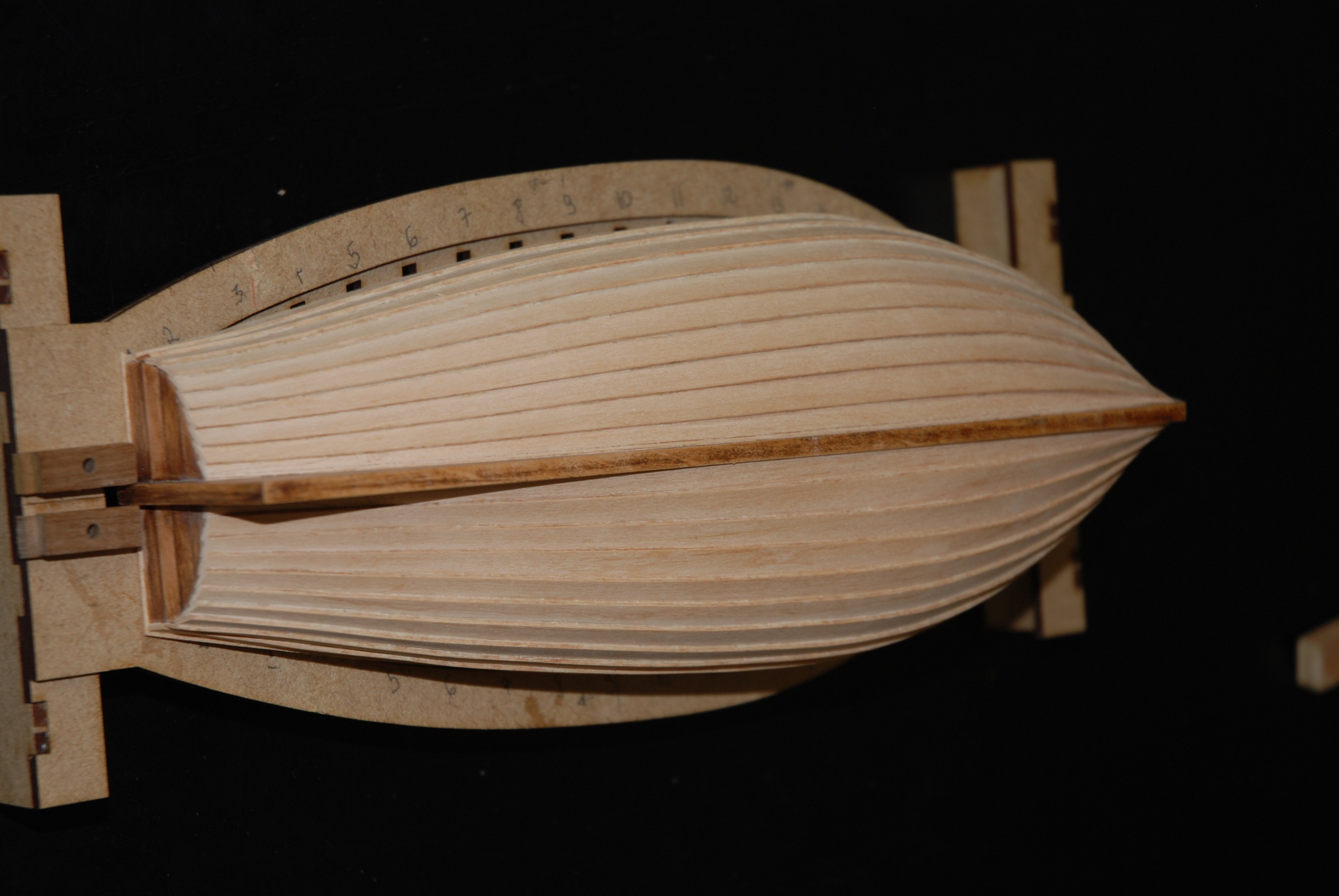
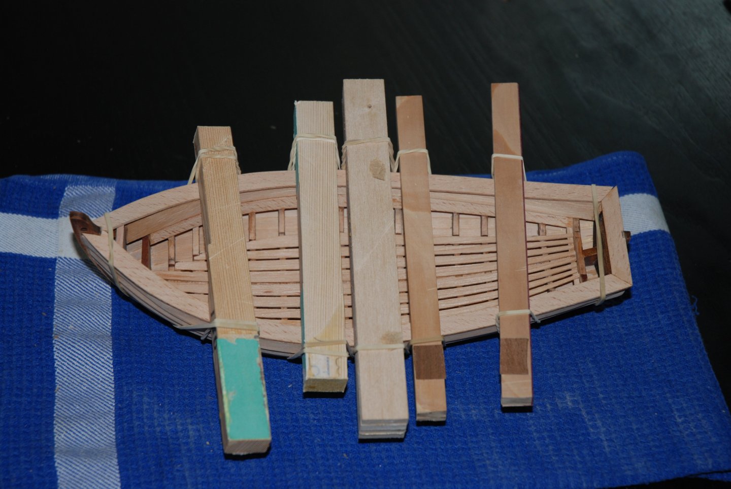
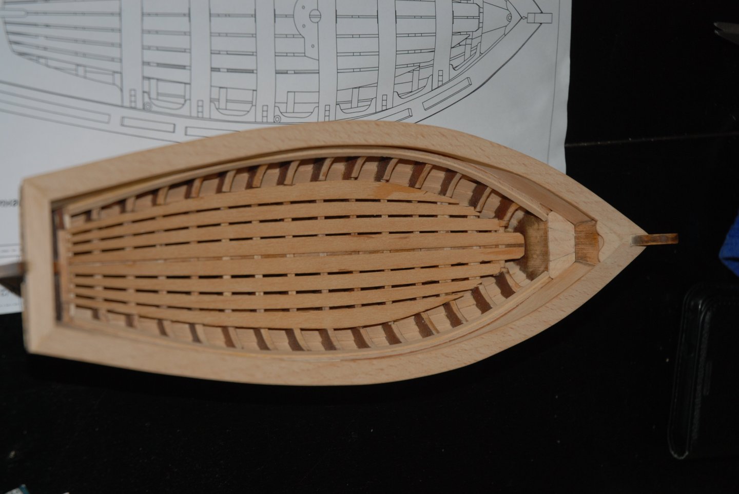
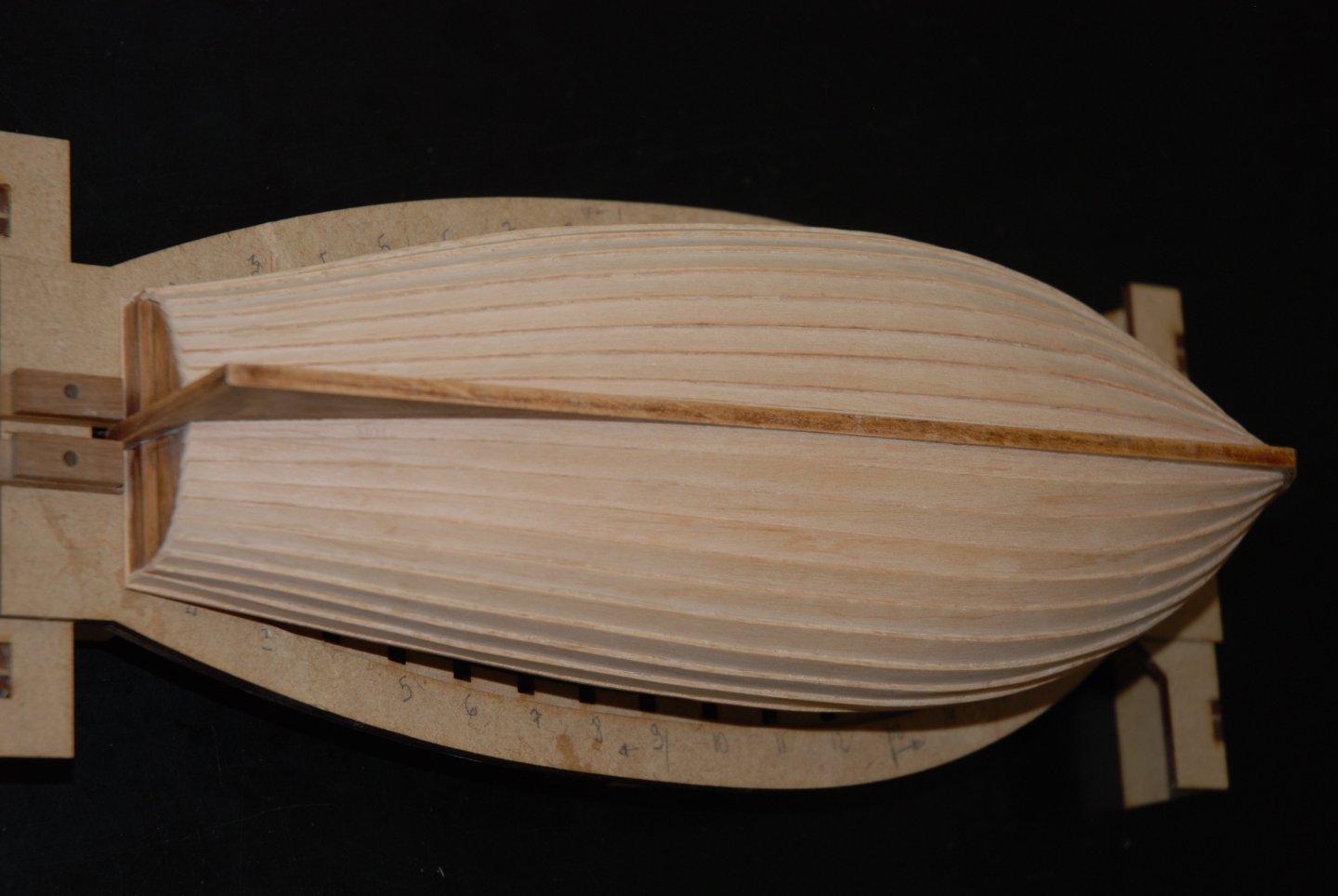
Thank you to all the 'Likes'. The latest planks have been installed using the method described above. The planks at the stern were cut to final length (first rough cut with a small saw, then sanded). And a first general sanding was carried out on the hull. Quite happy with the final result and no problems with the shape of the planks supplied with the kit. It makes the job much easier... The gunwale is being installed and I'll have to remember to add the nails and treenails. To be continued

- 22 replies
-
- 3
-
-
- ships boat
- Korabel
- (and 1 more)
-
HM Cutter Cheerful 1806 by JpR62 - 1:48 scale
JpR62 replied to JpR62's topic in - Build logs for subjects built 1801 - 1850
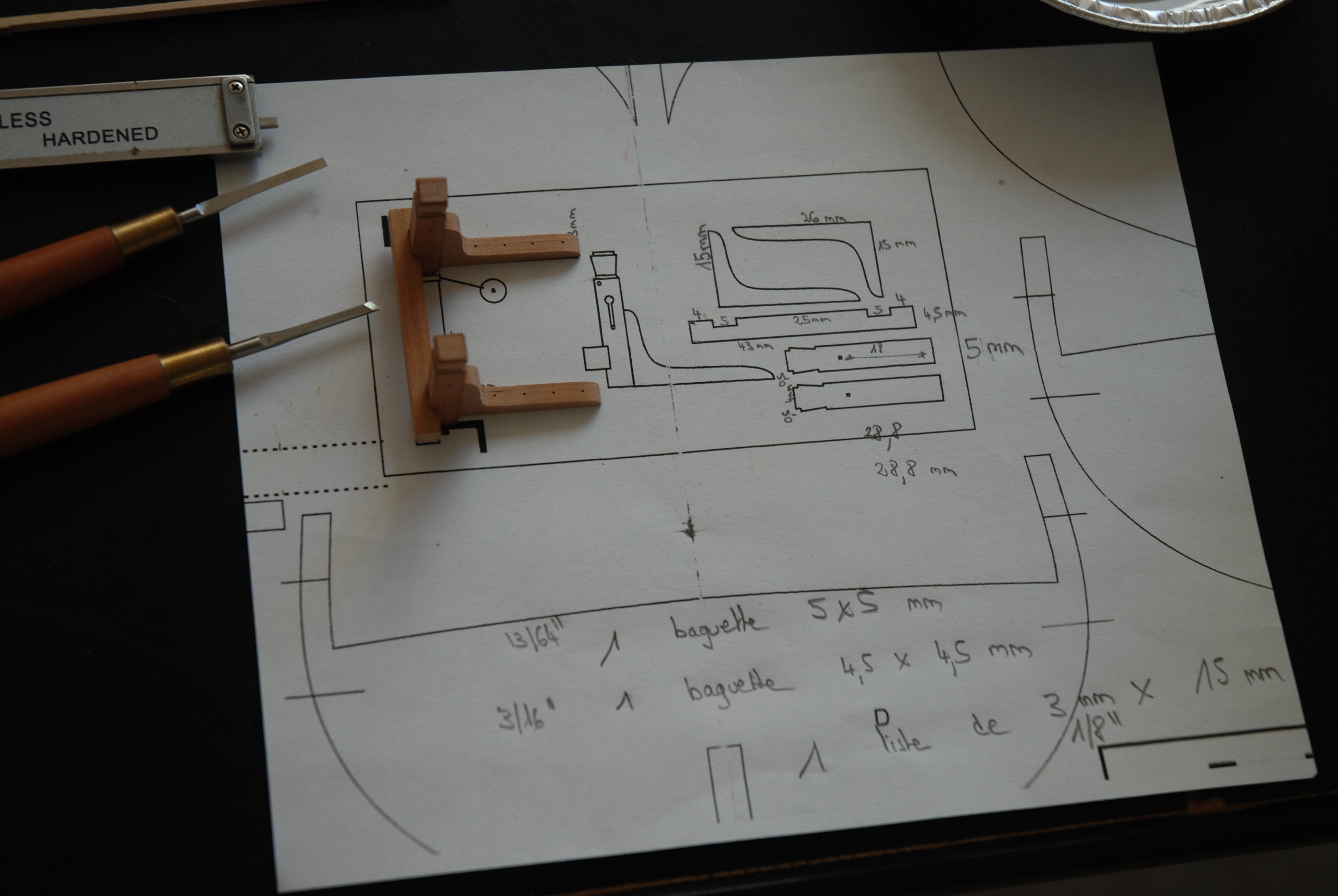
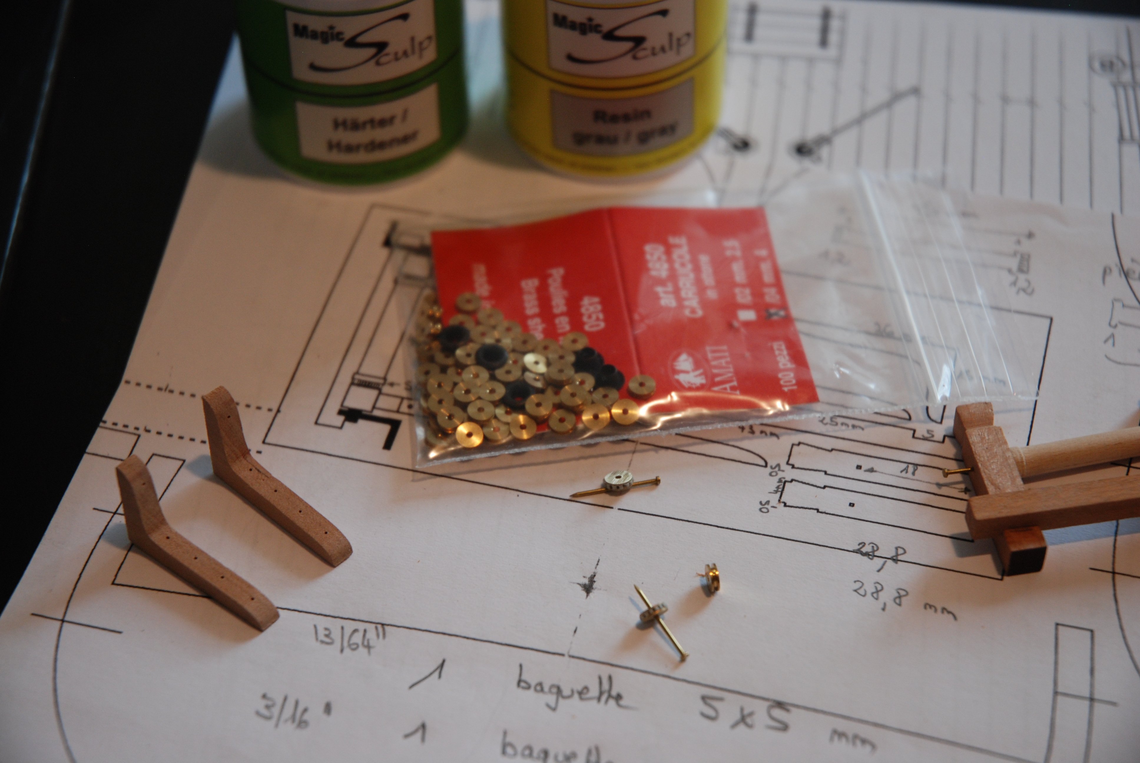
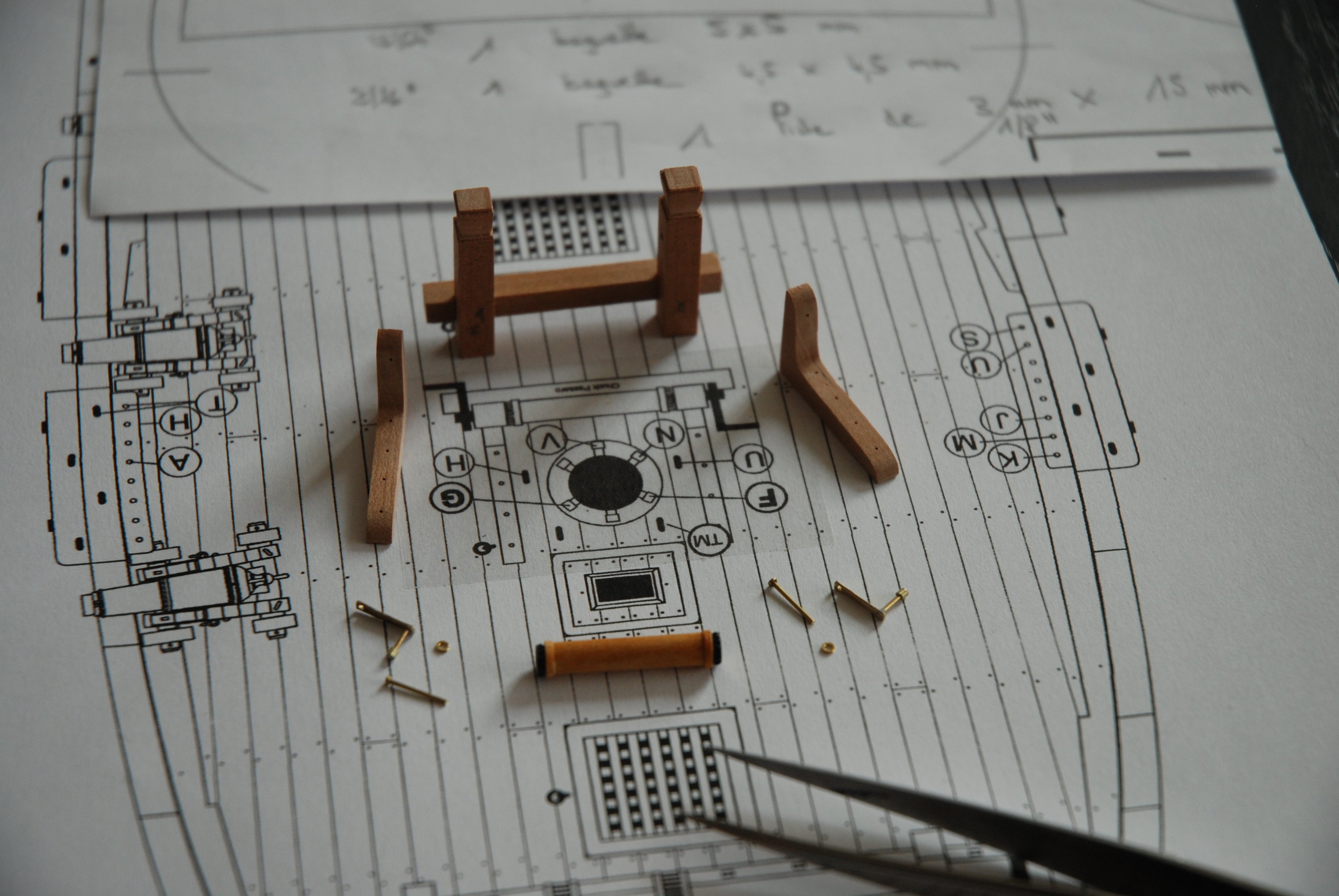
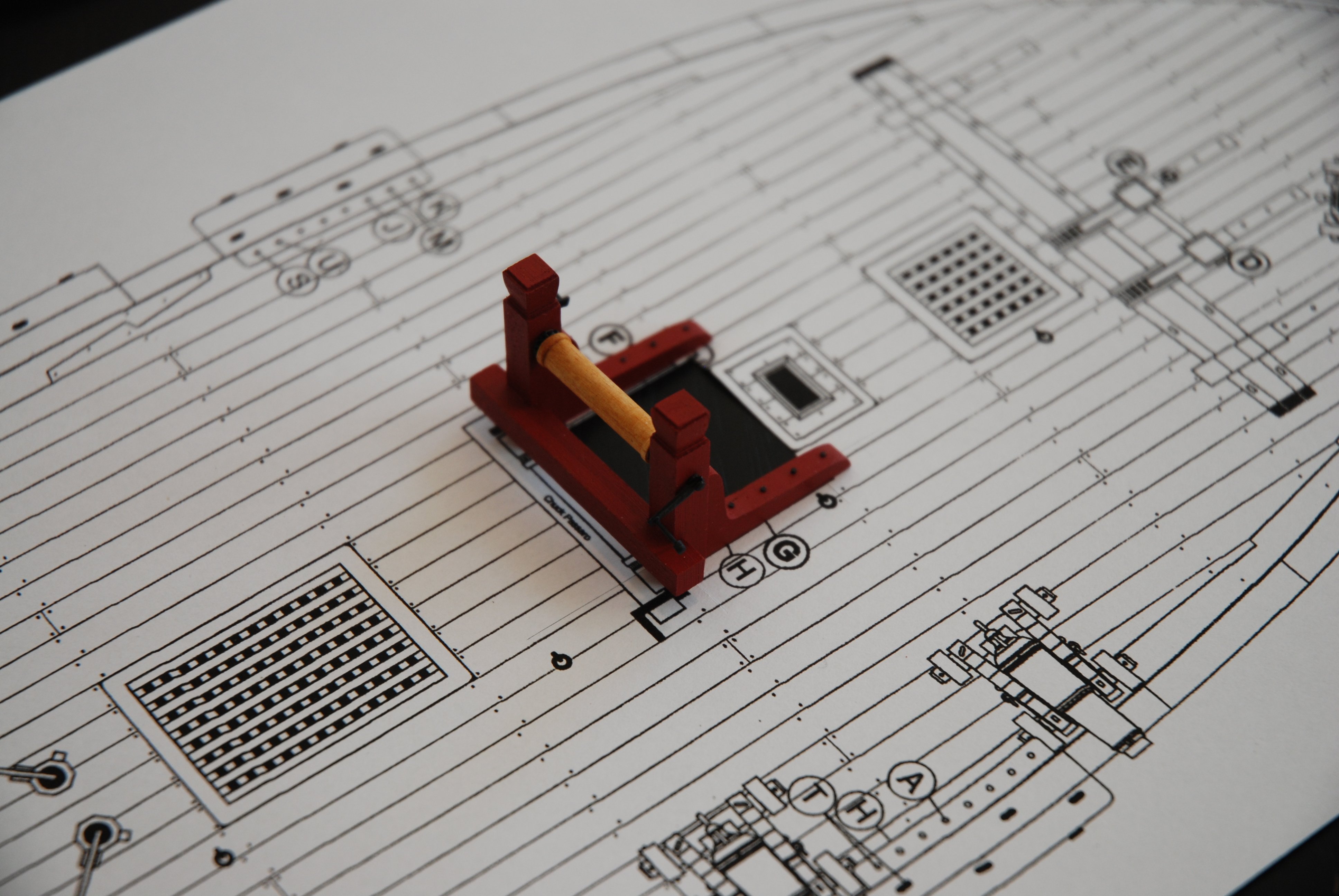
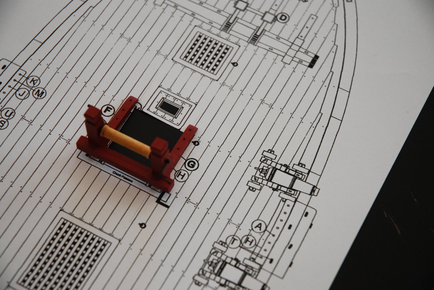
Thank you to all the 'Likes'. I went on to build the winch. All measurements were taken on a copy of the plan and noted directly on it. This enabled me to determine the wood cuts to be made. I used cherry wood (with the exception of the winch drum, which will be turned from a boxwood plank). To simulate the two small sprockets, I decided to make them from two 2.5 mm Amati brass sheaves. At least I'm sure I'll get two perfectly round sprockets... To simulate the teeth, I simply filled the pulley slot with two-component epoxy putty and used the point of a needle to create the hollows between the teeth. The handles are constructed from metal wire and small sections of micro-tube. All parts are ready for winch assembly. The wooden parts of the winch are glued together, with the exception of the drum. Airbrush coloring. The metal parts have been chemically blackened. Then all the parts are finally assembled. A great little project that was finished and gave me a lot of pleasure. I'll be moving on to the last elements of the ship's deck center.


-
Many thanks for your research! So I'll probably add those clench nails as well as those treenails. It was definitely something I'd been wondering about, but I didn't dare extrapolate and invent a way in which the boards were fixed. And so far, no constructed version found on the net had been able to answer my question... Thanks again.
-
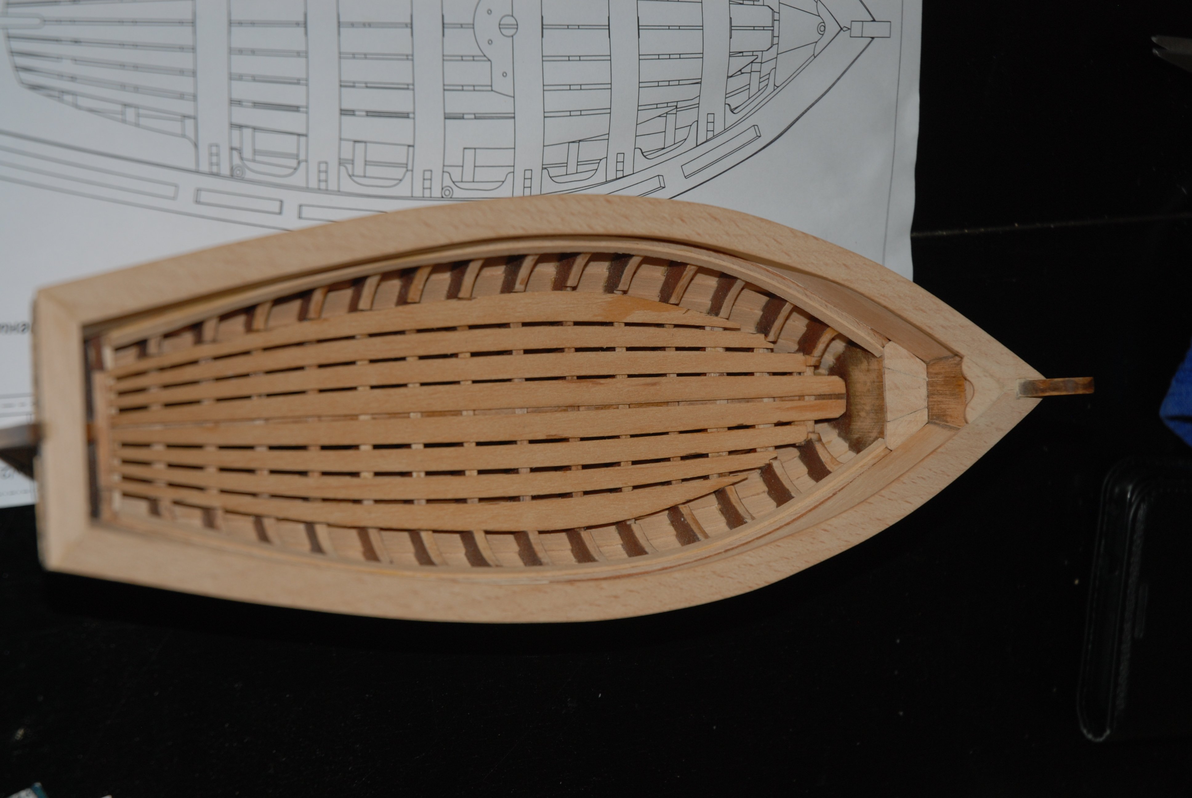
Yes, I can confirm that. The Santa Maria's boat is much simpler than Captain Smith's shallop. The Santa Maria's boat is a very interesting project to be carried out either between two larger projects or in parallel. After completing the structural work on this boat, I went on to build the Captain Smith's shallop. The design is very similar, but the boat is much more complex and contains additional elements. The scale is also different (1:32). But it's still a very, very interesting little project. I'll soon be starting a log on its construction. If, like me, you are interested in both models, I can only advise you to start with the Santa Maria boat.
- 22 replies
-
- 1
-

-
- ships boat
- Korabel
- (and 1 more)
-
Unfortunately, I couldn't find any information on this subject. The instruction manual provides no information on how the planks were fastened. And all the photos found on the net of the finished model show it without tree nails. So, for the time being, this is how I'm going to present it. In the book 'The Ships of Christopher Columbus' (Anatomy of the Ship), there's only one plate on the boats (plate H on page 80), which includes only drawings on the hull frames, with no text. And finally, I also have a PDF version of the book (in Spanish) 'Los Galeones Españoles', Volume II of which covers rigging, artillery and equipment. Unfortunately, the short section on boats describes only the dimensions and equipment of the boats, and the drawings again show only the frames... But if anyone has more information on the subject, I'd be interested too... Thanks again for your interest in this model.