


JerseyCity Frankie
-
Posts
1,338 -
Joined
-
Last visited
Reputation Activity
-
 JerseyCity Frankie reacted to shipaholic in HMB Endeavour by shipaholic - FINISHED - Eaglemoss - 1/51
An exercise in scale comparison
-
JerseyCity Frankie reacted to shipaholic in HMB Endeavour by shipaholic - FINISHED - Eaglemoss - 1/51
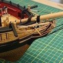
Been a while since I posted. Adding blocks and footropes to the fore yard
-
JerseyCity Frankie reacted to woodeater in Way of installation of guns on ship model
Temporary fitting of guns on the places
-
 JerseyCity Frankie got a reaction from DarkAngel in Sandpaper. Use. It.
I debated writing this but then thought it couldn't hurt: sandpaper. Use it! I don't want to name and shame anyone, but there is a huge proportion of finished models displayed on MSW on which the detailed photos of deck fittings or mast details show a lack of adequate sanding and surface prep. It looks like a lot of builders punch out the laser cut parts and incorporate them directly into the model without sanding to an adequate degree. I KNOW that close up photography of small parts reveals flaws not visible to the naked eye but some of the model photos I see show that a lot of small wooden parts are going onto models without enough sanding taking place, the surfaces are often covered in irregular globs bumps and spikes.
since most kit models are basswood, it helps to recognize that the biggest drawback of basswood is it's fuzzyness. In other respects it's a great material but at the near-microscopic level fibers at the edges are very stringy, they don't break off neatly at the surface of the wood but cling on randomly as fuzz. Paint or varnish going on over this fuzz only serves to make the fuzz bolder and stick out in hardened spikes and that's what I'm looking at in these detail photos I'm seeing. I'm going to make another plug for the use of a Sanding Sealer. Available in any hardwear store, one can should last your entire modeling career. I use a water based Minwax Sanding Sealer. It paints on like thin acrylic paint, completely transparent. When dry it has the effect of darkening the wood just a bit. Is that so bad? The surface you get has hardened and feels shellacked. When you go over it with fine sandpaper those annoying stringy grainy fibers break right off at the surface in a way that reminds you of those old animated cross sectional shaving razor commercials in which each hair is lifted and cut perfectly at its base. You get a smooth surface where the grain is still visible but not in the form of huge peaks and deep valleys, a surface that can withstand the scrutiny of close-up miniature photography.
-
JerseyCity Frankie reacted to dafi in HMS Victory Rudder- rigging
I do not think, that it should be that tight, as the rudder must
- move with the tiller
- in case of emergency the rudder must have enough space to unhinge without breaking this chain.
Anyway this is the setup of the 1920 Vic. The original model of 1765 shows thos lien to move through the channel board and to be continued up to the poop where it is fitted onto a knighthead.
http://collections.rmg.co.uk/collections/objects/66473.html SLR0512
-
JerseyCity Frankie reacted to cdrusn89 in US Brig Niagara by cdrusn89 - FINISHED - Model Shipways - 1/64 scale
Tragedy strikes on the first day of year two of my Niagara build. While tensioning the TG yard halyard the TG mast broke at sheave (aka hole) where the halyard passes through the mast. Must have been a weak point in the wood - I was not pulling that hard. Anyway I was too distraught to take any pictures.
Since the TG masts are the same both Main and Fore, I got the Fore one and was able - so far - to get it in place. I will have to adjust the TG shrouds and remount the Royal and TG yards but I think the real issue I making another TG mast. I am not sure I have the right size yellow cedar (all the masts were made from square section yellow cedar left). Once I get the main mast back where I was I will have to take a look.
So here is the Main Mast with the Top Gallant and Top Sail yards in place. The Royal yard is going to need some additional repairs before it can go back on the mast. Nothing a few hours at the workbench won't fix but that delays the Course yard and building the new Fore Top Gallant mast a bit more.
-
JerseyCity Frankie reacted to davyboy in Ship paintings
Hi Shipscat,
I am British and also an ex serviceman so I reckon I can make a one line comment if I wish. And what I said is in the main true. Incompetent General Staff Officers had much to do with the many debacles including Gallipoli in WW 1. Donkeys adequately sums many of them up.
My apologies to Vegaskip for posting this in his thread.
Dave
-
 JerseyCity Frankie got a reaction from Peter Bloemendaal in US Brig Syren by Peter Bloemendaal - FINISHED - Model Shipways - 1:64
Certainly I've always loved wooden sailing ships. But after seeing the photos of your build as it approached completion, I love wooden sailing ships EVEN MORE.
-
JerseyCity Frankie reacted to captain_hook in Armed Virginia Sloop By captain_hook - FINISHED - Model Shipways - Scale 1:48
I haven‘t found the time yet to finish the gun tackles due to some nice spring weather to go out with family. But finished some mast hoops to replace the cast ones.
-
JerseyCity Frankie reacted to dafi in HMS Victory by dafi - Heller - PLASTIC - To Victory and beyond ...
Thank you Gary and Mark.
As long as I still keep gathering the input for 1805, I kept working on the version of 1765 to 1788 (great repair) or 1797 (decommissioned).
Luckily I did 2 slices in the old and long forgotten days :-).
One was fitted with deadeyes and chains, but proved to have some inaccuracies, that is why I decided to keep on working on the other one.
First came the frieze. First the base with the medium color then the shadows and the highlights.
One can see that the chain board was removed. was atop the whales and not on them. The good thing on the painting technic that I use is, that repairs can be nicely done.
First the priming with the classical small pots from Humbrol/Revell.
The 2 shades of brown with the casein paint and blended with the mostly dry brush. As the knees will be on the same place, I took it easy on that part 😉
Replaced the chain boards and gave it a new color suiting the 1765 model.
As it was too easy until now, I decided to open one gun port. So back to the heavy machines do dig deep ...
... cleared the back too ...
... and faked the inside boards.
Yes I mean faked 😉 ...
Also the port with the half lids was updated.
And then some paint and the reason for the opening. The model shows an interesting color scheme for the middle deck: White insides of the ports with a red rabbet.
Cheers, Daniel
-
JerseyCity Frankie reacted to Peter Bloemendaal in US Brig Syren by Peter Bloemendaal - FINISHED - Model Shipways - 1:64
I added the stuns'l booms to the yards and pinned the Topsail and Lower yards onto the masts.
They are just dry fitted and the yards assemblies are not completed yet. I have decided to keep them natural and not paint them black.
Some photo's......
-
JerseyCity Frankie reacted to GrandpaPhil in Prince de Neufchatel by GrandpaPhil - FINISHED - 1/72 - CARD - from Chapelle Plans
I have reached another milestone with this build. I am done with the standing rigging.
Next up, I will be making some booms, gaffs and yards.
Then, I will make sails.
After that, I have to install everything and install the running rigging.
The last thing I do on any model is to make and install flags and pennants.
As a quick side note, I never expected this model to get past the hull covering phase, but I’m too stubborn to give up. So, I’m pretty pleased with my progress. I’ve never scratch built a model before so I’m very happy with it. It’s not perfect, but it’s good enough for a first run. I’ve learned a lot and have gained much valuable experience that will help me in future builds.
Without further ado, I present the American Privateer Prince de Neufchatel with the standing rigging complete:
-
JerseyCity Frankie reacted to GrandpaPhil in Prince de Neufchatel by GrandpaPhil - FINISHED - 1/72 - CARD - from Chapelle Plans
Davits are done and installed.
Ship’s boats are mostly done. Still need to paint the two larger boats.
I made four double blocks to hang the little cutter from the stern.
I put some belaying pins in two of the pin rails. They are made from sewing pins.
This is how I’m leaving the Prince de Neufchatel for the night.
-
JerseyCity Frankie reacted to GrandpaPhil in Prince de Neufchatel by GrandpaPhil - FINISHED - 1/72 - CARD - from Chapelle Plans
Note, this is being mostly built from posterboard.
-
JerseyCity Frankie reacted to Chuck in HMS Winchelsea - FINISHED - 1764 - by Chuck (1/4" scale)
The lower counter was planked with laser cut strakes. One thing I noticed on other projects is that some folks find it tricky to bend or cut these strakes to the proper curve. This is very important because it determines the shape of the upper counter and thus the quarter gallery etc....and it just compounds from there. So these strakes are laser cut. I started with the top of the counter and worked my way lower where the final pieces were placed on either side of the stern post. This will be covered over with a frieze but I added simulated caulking anyway. I wanted to test how much would be used elsewhere. Running a pencil along one edge of the joint was perfect.
The wales were stated and this is another crucial moment. The run of this first plank will determine a lot. The etched marks and references I made after running the batten were used to line up the bottom of the first strake. I added this first strake with the hull upside down using 7/32" x 3/64" strips of cedar. I still made adjustments after I finished the strake to try and get a smooth run.
I dont care about using a pencil to simulate tared seams on these. This is just the first layer. I used the plans to determine where the butt joints fall (4 butt shift). I added this lower wale strake on both sides before working my up to complete them. All four strakes for the wales are 7/32" wide.
Then it was just a matter of adding three more strakes above that one. Note how there is no caulking but each strake was carefully added so the seams were nice and tight. I did have to pre bend the lower two strakes of the wales at the bow edgewise. This was done as an alternative to spiling the curved shape needed at the bow. Its the only way you will get the planks to lay flat against the bulkhead edges.
I used a hold-down jig in the center as the pivot point which has a slight curve to it. Then I clamp the plank on either side after bending it as needed. Note the scrap wood pieces used to help prevent the soft cedar from denting. As usual I uses a hair dryer on the hottest setting to heat up the strip and then let it cool down before removing it. The curve you need is very slight. No need to over bend these yet.
The first layer of wales on the starboard side are completed...all four strakes. Now to complete the other side.
Chuck
-
JerseyCity Frankie reacted to Chuck in HMS Winchelsea - FINISHED - 1764 - by Chuck (1/4" scale)
Thank you very much!!! And happy Easter!!!
I didnt feel like actually working today so I finished the starter package. The last items to be completed were the bollard timbers. Just like most projects, there is at least one item that will prove very tricky and challenging. The bollard timbers arent too bad though. They are similar in difficulty to making those "bolsters" at the bow of the longboat. Every model has at least one or two complex parts to shape. Its not unusual but most kits usually drop the ball on how these items are presented.
I believe its just a matter of breaking the process down into many steps ahead of time so mentally it becomes a lot easier. Each individual step is not very difficult and once completed, you have shaped a very complex piece of modeling.
The bollard timbers at the bow are laser cut as blanks. You need to make a pair of these that match as mirror images. In the center, a chock spans the gap between them. Here are the blanks which are 1/4" thick.
Before you begin, it is important to fair the inboard side of the hull. The bulwarks and stem need to be reduced to 1/8" thick. You dont have to fair the entire hull inboard....just up towards the bow. Its easier to shape the bollards after fairing and having the bulwarks thinned down.
Then place the bollard timber in position so the inside edge sits flush with the rabbet as shown. But make sure you sand all of the laser char off first. This will help keep the piece clean as you shape it. In fact your hands should be washed and super clean once you get the char off. You will be handling these pieces a lot and they will get dirty otherwise.
This piece will stand proud of the bulwark framing so that the exterior planking will be level/flush with it. Therefore, you must create a bevel on the front and back sides. Once placed in position, use a 3/64" thick plank that has been beveled (just like you would when planking) and position it along the bollard. Then draw a line down the edge which will determine the bevel needed. This needs to be done inboard as well. Note the bollard timber on the port side is already completed. I will attempt to make a mating pair. There is a very detailed drawing on the plans for these parts.
The photo below shows the bevel completed on both sides.....note the finished example which I keep handy so I can make a matching pair.
Next, file the round cut-out that forms the top using a round needle file, sandpaper etc. You can use the shape created by the laser on the other two sides to guide you.
Then draw a line just below the where you filed. Do this on all four sides. You will be filing a groove all around the piece. I actually used a #11 blade to make a stop-cut on the line. Then I chiseled a bit off towards the line on the top side. I then rounded it off so it looks like the plan.
This is what it looks like completed. But you will also notice that I cut a little skewed square from a 1/64" thick strip. Its very thin but still not thin enough. This should be glued on top of the bollard timber to "simulate" a nice carved detail. This detail would be much harder to carve and file into the top so I cheated and glued a separate piece on top. After I glued in position, I sanded it even thinner to about half its original thickness.
This is what it looks like....below...but we are not done yet!!! The circular slot for the bowsprit still need to be filed on an angle to match the stem. You can position the bollard on the model and draw a line to follow when you start filing. This is shown below. Once that is completed the bollard timbers are finished.
They can be glued on the model and then the cross chock positioned between them. Sand the char off before you do this. You will also need to sand the same angle into the bottom of the chock so the circular opening will accommodate the bowsprit. The photo shows this all done and the chock glued into position. It was sanded flush with the bollard timbers inboard and out.
Remember that I am making this model out of Yellow Cedar. You can see how well it holds an edge with these tricky timbers. No finish has been applied yet. But the softness of the cedar made it very enjoyable and easy to sand, file and carve.
-
JerseyCity Frankie reacted to archjofo in La Créole 1827 by archjofo - Scale 1/48 - French corvette
The ropes for the hammock cranes have to be tensioned. I did that with tiny thimbles Ø 1,1 mm and lashings.
The thimbles on the next image have the following diameter from left to right:
Ø 1,1 mm
Ø 2,2 mm
Ø 2,6 mm
The first attempts with seizings are not very nice.
With a "fake splice" it looks better?
-
JerseyCity Frankie reacted to GioMun in Le Coureur by GioMun - FINISHED - Scale 1/48 - using Jean Boudriot's monograph
Hello!
It's been a long time since i posted the last time. Actually it was in the old fórum.
In these last years i'm been building the lougre Le Coureur. It has been my first Arsenal model, so it took a lot of mistakes, and time to figure out how to keep doing it.
One of the first "issues" to resolve was the clinker built planking, wich it came out how you see it in the pictures. Then, every step was taken very carefully, triyng to keep as "arsenal" as posible. I even had to remove the white paint on the hull, because i didn't like the effect achieved.
Fortunatly, the Boudriot gives every explenation of what you need, and thanks to Mr. Delacroix, and the guys on his fórum, i could find a lot of answers too.
And of course here too! That's why i'm presenting you this model, wich some of you may remember from the old fórum, and for those that are knowing it for the first time, i hope you like it.
Today my LC it is about to get finished, so i post picutres in chronological order to undrstand how the construction was made. And i'll be happy to keep you informed, if you are interested of course, of the finishing of this project.
I hope you join my adventure!
So, pictures......
-
 JerseyCity Frankie got a reaction from Bob Cleek in yards before sails?
The quick answer, in my view anyway, is to dress the yards as much as you can prior to installation. Getting in close to the mast with your hands and tools will be tricky once the shrouds and stays are rigged.
-
 JerseyCity Frankie got a reaction from mtaylor in yards before sails?
The quick answer, in my view anyway, is to dress the yards as much as you can prior to installation. Getting in close to the mast with your hands and tools will be tricky once the shrouds and stays are rigged.
-
JerseyCity Frankie reacted to rwiederrich in Great Republic 1853 by rwiederrich - FINISHED - four masted extreme clipper
After some further research and discussion with some informed friends...I opted to add sunsail booms to the main yards and the upper topsail yards.
Lots more work to do but its a beginning.
Rob
-
JerseyCity Frankie reacted to rwiederrich in Great Republic 1853 by rwiederrich - FINISHED - four masted extreme clipper
Still suffering from an extremely sore arm..but I managed to wrestle through some minor items today.
I rigged the mizen lower stays first...
Here is some pics.
-
JerseyCity Frankie reacted to rwiederrich in Great Republic 1853 by rwiederrich - FINISHED - four masted extreme clipper
It took me twice as long to make sure the lines didn't foul one another as I reran them down the mast to the belay pins.
Everything has to follow a set sequence or I will risk twisting and crossing future lines.
Shrouds are next...but I can choose to finish the main mast backstays first, being cautious not to over stress the mast without counter acting with the top main stays. Its a puzzle from here on out.
Here are a few other images.
Rob
-
JerseyCity Frankie reacted to Mr. Hornblower in Template for Naval Cutter Build
Hello All,
I thank you all very much for your welcomes and replies.
I had two vessels in mind, firstly the Cutter Sandwich of 1805 (same ship as the Sandwich of 1798), or the Entreprenante of 1799. I do not know of any pictures, models, illustrations of Sandwich to actually exist, but you chaps may be able to tell me otherwise.
I have just acquired the plans for the Alert of 1777, but as Bruce said, there is a difference between plans and bulkhead/rib templates! I was hoping for a template of sorts. Another thing to let you all know: as this is my first scratch build, I have decided on doing a card/paper model, similar to that of the Alert by Shipyard models. I do not have all the timber machinery, but I have always enjoyed making things from cardboard, so I will try my hand at a card/paper model (with extras such as dowel for mast/bowspirit etc).
Thanks again.
Cheers,
Caleb
-
JerseyCity Frankie reacted to Stuntflyer in The Hayling Hoy 1760 by Stuntflyer (Mike) - 1:48 scale
Welcome to my build log of The Hayling Hoy. This will be my first attempt at building a POF model. I am building Hayling from the plans drafted by David Antscherl, based on plans and documents in the Royal Museums Greenwich collection. I would imagine that without the RMG , that this build would never happen. So, a special thanks to the museum for making this build possible.
Being a first attempt, I expect that there will be many do-overs along the way. In anticipation of that, I ordered 50% more boxwood sheets than the build would normally call for. All of the wood was supplied by Jason at Crown Timberyard. To play it safe, I went with 2" instead of 3" widths which should help to maintain flatness in the wood. To lessen the need for thickness sanding, Jason was able to supply sheets a few thousands over the scale inches needed.
Much of the information for the build will be referenced from "The Fully Framed Model" Vol I thru IV at SeaWatch Books. https://www.seawatchbooks.com/SWBTitles.htm
Before getting started, here are a few words from David Antscherl. .
The Hayling hoy
© David Antscherl 2017
What is a hoy?
hoy, (bateau de passage, Fr.) a small vessel, usually rigged as a sloop, and employed in carrying passengers and goods from one place to another, particularly on the sea-coast, where ordinary lighters cannot be managed with safety or convenience. It would be difficult to describe, precisely, the marks of distinction between this vessel and some others of the same size, which are also rigged in the same manner; because what is called a hoy in one place, would assume the name of sloop or smack in another; and even people who navigate these vessels have, upon examination, very vague ideas of the marks by which they are distinguished from the above-mentioned. In Holland, the hoy has two masts; in England it has but one, where the main-sail is sometimes extended by a boom, and sometimes without it. This prolix, sub-clause filled entry in William Burney’s 1815 edition of Falconer’s New Universal Dictionary of the Marine leaves much to be desired in way of precise definition. Looking at plans of lighters and hoys, they seem to have much in common. Falconer defines a lighter as follows:
lighter, (barque, ou gabare, Fr.) a large open flat-bottomed vessel, generally managed with oars, and employed to carry goods to or from a ship when she is to be laden with, or delivered of, her stores, &c. However there were also sailing lighters, very similar to hoys. These were about 60 to 70 feet in length. Both had fairly similar hull forms and were also usually sloop or cutter rigged. Lighters were distinguished from hoys by the heavy davit (or sometimes two) carried forward over the bow. The other difference seems to be that only hoys carried passengers as well as goods.
Where does the name hayling come from?
Hayling Island, shaped like an irregular inverted ‘T’, is located close to Portsmouth, Hampshire. Portsmouth lies to the west across LangstoneHarbour and to the east side is ChichesterHarbour. The island is connected to the mainland by a bridge at its narrower north end. An iron-age shrine built on the island later became the site of a Roman temple. Salt production on the island, recorded in the Domesday Book, continued until the late 19th century. A chapel was established on HaylingIsland sometime in the 12th century. This became St Peter's Church, now the oldest surviving church there. Its peal of three bells, cast in about 1350, is considered one of the oldest extant in England. In 1944 the island was used for a mock invasion exercise as part of preparation for D-Day. Oyster farming was carried out for many centuries, and the oyster beds are now being restored.
That the hoy would be named after the island is appropriate, as she was designed to work in the adjacent Portsmouth harbour.
Why a model of a hoy?
The choice of Hayling as a subject was chosen for several reasons. First, it is a subject rarely seen in model form. Secondly the hull, if fully framed, is considerably less complex to construct than even that of a sixth rate, but still illustrates all its principal features. There are no ports or sweep ports to frame. Also, there are very few chocked joints required in constructing the frames. The frames consist of fewer pieces than in larger vessels. Neither does a model of this size consume many board feet of expensive exotic wood. All these features make her an ideal subject for a first effort at ‘real’ framing. In addition, Hayling’s rig is comparatively simple. A rigged model, even at 1:48 scale, will not take up too much space. Lastly, there is no carved work. Carving is something that puts off many model-makers from tackling 18th century subjects. The only ornament, a simple scroll head, is a relatively easy feature to model.
A brief history of the Hayling hoy.
Hayling was constructed by the well-known builder Henry Adams of Buckler’s Hard. Nelson’s favorite, Agamemnon of 1781, 64 guns, was one famous product of his shipyard. Others included Indefatigable, also of 1781 and 64 guns, and the frigate Euryalus of 1803, 36 guns. Buckler’s Hard is situated 10 miles upriver at a bend on the west side of the BeaulieuRiver. The lower tidal part of the winding river enters the Solent opposite the Isle of Wight near Portsmouth.
Hayling was the third vessel of that name. The first Hayling, of 117 tons, was purchased in 1705 and rebuilt at Portsmouth Dockyard in 1729. The second, actually the rebuilt, Hayling, also spelled Heylin, was converted into a sloop in 1759 for use as a floating battery off the coast of Africa. This triggered the order to construct her replacement, the third Hayling.
“New Hoy propos’d in ye (the) Room of ye (the) Hayling” was written on a draught (zaz 5828) signed Allin and dated 30th August 1759. Joseph Allin was joint Surveyor for the Navy with Sir Jacob Ackworth. A copy of another draught (zaz 5829) was sent to Henry Adams on 27th September as “per contract”. Hayling was launched the following year in 1760. After 22 years of service, she was lost when she foundered in the Channel in 1782. (David Lyon, The Sailing Navy List 1688-1860, page 321.) This was a lengthy working life for a knock-about service vessel.
Hayling’s armament, if any, is not recorded. Two of four of her draughts that are extant -dated August and September 1759 - show four swivel mounts on each side. However, her ‘as launched’ draught, zaz 5830, does not. Whether swivels were actually fitted or not is unknown, but probably unlikely.
Sources of information
The primary source of information is through the draughts held by Royal Museums Greenwich, formerly The National Maritime Museum. There are four draughts extant. The first is a design draught showing a scroll head dated 3rd August, 1759 (zaz 5827). It shows very little detail and some pencil alterations have been sketched along the topsides.
The second draught (zaz 5828) is dated 30th August 1759. It shows a fiddle head and for swivel mounts a side. Far more detailed than the first draught, it includes the profile and weather deck details in red ink. Titled “New Hoy propos’d in y(e) Room of y(e) Hayling” this draught has the signature of approval of Joseph Allin, joint Surveyor of the Navy.
A third draught (zaz 5829) is also much more detailed, and is annotated as follows: “A Copy for this was given to Mr. Henry Adams for Building the Vessell (pr Cont’t) 27th Sept. 1759”. This also shows four swivel mounts a side and a fiddle head. There must have been more than one copy, as this draught is titled “A Copy of A Draught for Building A New Hoy in the Room of the Hayling for the Use of his Majesty’s Yard at Portsmouth”.
The fourth detailed ‘as launched’ draught (zaz 5830) gives a table of dimensions of all Hayling’s masts and spars. It is undated, other than a modern pencil annotation of 1760, but states that her ‘Draught of Water when Launch’d Fore 5(') 5( ") Abaft 7(') 0("). No swivel mounts are shown. This must be the yard draught that was subsequently filed with the Admiralty.
Further inboard details were gleaned from the draught of a 56' 0" mooring lighter (zaz 5895) dated 1764. This, conveniently, shows a cross-section from which I lifted scantlings for the longitudinal members of the vessel.
To start things off I needed to construct a building board. This was made from 3/4" x 10" x 27" M.D.F. It is supported by 1" x 3" pre-primed pine battens longitudinally beneath. 1 1/2" dry wall screws were counter sunk into the M.D.F. to hold the battens in place. After checking to see that the board was flat in both directions it was given two coats of primer using a roller.
The board drawing was then adhered to the building board with 3M Super 77 Spray Adhesive. Now, we have had a few humid days here and I noticed a slight wrinkling in the paper afterwards. This reminded me of some of the issues that Ben was having with his HMS Pegasus. In an effort to keep the humidity under control before this got even worse, I purchased a small room de-humidifier. In only a few hours the wrinkles disappeared. I keep the RH levels at 50% more or less.
Note: I extended the fore and aft cant lines to make it easier to setup those frames later on.
Mike