


shipmodel
-
Posts
908 -
Joined
-
Last visited
Reputation Activity
-

 shipmodel got a reaction from CiscoH in SS Mayaguez c.1975 by shipmodel - FINISHED - scale 1/16" = 1' (1:192) - Dan Pariser
Hello again to all –
Thanks for the comments and likes, as always.
It has not been that long since the last segment, but since this is a retrospective of the build I can get another one out quickly, as long as I have time left over after the honey-do list. This one is a bit wordy, with only a few photos since I concentrated on building and not taking photos of my progress. I hope that the explanations will be sufficient.
In the second segment, posted a while ago, the superstructure was in the middle of construction based on the available photographs. To remind you, here is a close-up of the best photo of the superstructure and a ‘plan view’ taken by a US Air Force plane from almost directly overhead.
At that time all of the decks and deck houses had been built and the doors, handrails, ladders, and railings for the lower decks had been installed. The structures of the top two decks and the bridge had been built up but not detailed. Next the funnel was built. It started with a ¾” birch dowel that was carved down to an oval cross section.
The dowel was wrapped in 0.02” styrene attached with gel cyano. The seam was not positioned along the aft centerline but was offset to one side. I find that even after filling, sanding, priming and painting there can be a slight imperfection in the surface. I think that it is less noticeable if it is not centered, which is where most people look. A reinforcing collar was made for the bottom of the stack from 0.015” strip, painted black. At the top the photos seem to show that there is a narrow lip enclosing a large round exhaust fitting and a much smaller pipe, probably for excess steam. A homemade decal of the SeaLand logo was created in my printer and applied to both sides of the funnel. Actually, this decal ultimately looked too small so you will see a larger one in future photos.
Directly ahead of the funnel is a large, square fitting. I could never be sure of its shape or function, but in one of the fuzzier photos there is a hint that it might be a raised hatch with open doors on either side. The interior can’t be seen at all, but could contain filters for an air intake. I modeled it that way but I ask anyone who has a better idea to let me know. I believe that the six capped square tubes that stand alongside the funnel are the exhausts for the ventilation system. Their relative heights were taken by comparison with doors and railings in the photos. They were made slightly overlong, then trimmed to a height that ‘looked right’.
The lifeboat davits were Frankensteined from two cast pewter fittings from Bluejacket. The top arm of a 7/8” davit could be ground to a thinner profile that closely matched the photos. But the slides were not long enough since the deck had been widened and the lifeboat had to travel further to reach the edge. I cut off the foot of one fitting but cut the second fitting higher up the slide. Mating these two gave me the length that I needed. They were secured with a bit of brass wire across the joint then filled and glued together with an epoxy product called ‘JB Weld’ that has metal particles in it. I find that it gives one of the strongest bonds across small metal mating surfaces.
The detailing of the upper deck and bridge continued with the large radar mast. It was built up from a length of 1/8” brass tubing with a 0.032” brass rod crossarm for the signal flags. A PE ladder leads up to a round lookout platform with a bit of PE railing curled around a dowel to fit. A radar dish was fashioned from several PE fittings. Although it looks good and matches some photos of the ship, further examination of the photos taken during the incident showed that the radar at that time was a solid bar. This radar was removed and a more correct one was built and will appear in later photos. Four guy wires made of fly tying thread were installed later.
Two small exhaust stacks were fitted to the forward corners of the bridge house. They were cut and carved with slots opened down their lower ends to fit over the forward bridge solid railings. Small sections of plastic tubes were heat bent then trimmed and painted black as exhaust pipes.
Final details include a smaller simple mast seen in the photos but whose function I don’t know. A radio loop was bent up from brass rod and installed as well. PE railings were fitted around all the deck and bridge wing edges and nameboards were printed with a type face that matched those seen in the photos. To get a sense of the sizes involved, the nameboard is just over 1/16" tall.
The lifeboat davits were made more accurate by sawing grooves in the integral sheaves where the lifting lines will run, then the channels in the slides were filed open and square. The davits were painted white with the sheaves and slide channels painted black. A Bluejacket casting of an open lifeboat was filed smooth and painted. After the lifeboat was installed over a square section support the lifting lines with PE blocks and tackles were run. A final line runs at the top from davit to davit for support. A final detail of coiled hanks of rope hung from this line will be installed later.
And here is the superstructure with all the final details added, such as the running lights, the guy wires, and the signal flag hoists with an American flag flying.
In the next segment the bow and stern decks will be detailed.
Till then, stay safe and well.
Dan
-
 shipmodel got a reaction from billocrates in 74-gun ship by Gaetan Bordeleau - 1:24
Hi Gaetan -
A tip of the hat to you and to Vossiewulf for clearing up my questions as to why some of the knives on "Forged in Fire" will not cut.
Your dedication to sharpness reminded me of Terry Pratchett's character Death, who hones his scythe on leather, then wool, cotton, silk, and even the wind. He finally gets the edge that he wants with sunlight itself. If you are going to sever the soul from the body you should have the sharpest blade possible. I guess every job has its need for its own kind of edged tool.
Dan
-
 shipmodel reacted to tlevine in Swallow 1779 by tlevine - FINISHED - 1:48 scale
Swallow is finished, other than a few touch-ups which will be addressed after I mount her. My plan is to duplicate the base from RMG as much as possible. It will probably take me a few weeks to source the wood and draw up the plans.
-
 shipmodel got a reaction from Mirabell61 in Germania Nova 1911 by KeithAug - FINISHED - Scale 1:36 - replica of schooner Germania 1908
Terrific work, Keith -
As one who has struggled with making and hanging sails, I am truly astounded with how well yours came out.
No need for a third hand when your two do such great work.
Dan
-
 shipmodel got a reaction from FriedClams in Germania Nova 1911 by KeithAug - FINISHED - Scale 1:36 - replica of schooner Germania 1908
Terrific work, Keith -
As one who has struggled with making and hanging sails, I am truly astounded with how well yours came out.
No need for a third hand when your two do such great work.
Dan
-
.thumb.JPG.33e8fc9704bbb01f03cf31c187b62df9.JPG) shipmodel got a reaction from Retired guy in Germania Nova 1911 by KeithAug - FINISHED - Scale 1:36 - replica of schooner Germania 1908
shipmodel got a reaction from Retired guy in Germania Nova 1911 by KeithAug - FINISHED - Scale 1:36 - replica of schooner Germania 1908
Terrific work, Keith -
As one who has struggled with making and hanging sails, I am truly astounded with how well yours came out.
No need for a third hand when your two do such great work.
Dan
-
 shipmodel got a reaction from mtaylor in Germania Nova 1911 by KeithAug - FINISHED - Scale 1:36 - replica of schooner Germania 1908
Terrific work, Keith -
As one who has struggled with making and hanging sails, I am truly astounded with how well yours came out.
No need for a third hand when your two do such great work.
Dan
-
 shipmodel got a reaction from michael mott in Germania Nova 1911 by KeithAug - FINISHED - Scale 1:36 - replica of schooner Germania 1908
Terrific work, Keith -
As one who has struggled with making and hanging sails, I am truly astounded with how well yours came out.
No need for a third hand when your two do such great work.
Dan
-
 shipmodel got a reaction from KeithAug in Germania Nova 1911 by KeithAug - FINISHED - Scale 1:36 - replica of schooner Germania 1908
Terrific work, Keith -
As one who has struggled with making and hanging sails, I am truly astounded with how well yours came out.
No need for a third hand when your two do such great work.
Dan
-
shipmodel reacted to KeithAug in Germania Nova 1911 by KeithAug - FINISHED - Scale 1:36 - replica of schooner Germania 1908
Onwards and upwards -------- it is time to start hoisting the mainsail.
I have 5 sails prepared with only the two topsails to do. Here are 4 of them, I'm not sure why I didn't photo the 5, I blame the onset of senility.
Because of the size of the mainsail it took a bit of working out how to support it while I did the rigging. What I really needed was that elusive 3rd arm. You would thunk that by now evolution would have sorted the problem.
Here is the start of the hoisting process.
One of the gaff bridles is attached temporarily to the mast head with a bit of string.
With this improvised support the throat halyard was rigged.
The next step was to rig the peak halyard.
The building frame proved very useful for temporarily holding the halyard tails.
Next I went on to rigging the mast hoops using the "Leacher" method. I improvised the knotting of the free ends. My decision to delay the installation of the main and fore mast shrouds proved to be very beneficial for access.
It took a while but eventually all the hoops were attached.
My knotting of the ends isn't very apparent so hopefully no one will notice my creativity!
Then I took a few shots to celebrate.
-
shipmodel got a reaction from FriedClams in Bristol Pilot Cutter by michael mott - 1/8 scale - POF
Michael -
I also missed your post about your hand injury, my friend.
Glad to see you back, and hope that your recovery was complete and satisfactory.
Be well
Dan
-
 shipmodel got a reaction from GrandpaPhil in SS Mayaguez c.1975 by shipmodel - FINISHED - scale 1/16" = 1' (1:192) - Dan Pariser
Hi JKC -
I find that the GMM railings are quite sturdy, although they will kink if mistreated. If a bar is bent it is easily nudged back into shape and stays straight. I also have some from Tom's Modelworks and agree that they are fragile. But they are useful when I need light railings. I have used Tom's sets of deck chairs and benches for the Titanic and they are great - highly detailed and in scale.
I use smooth, flat jawed pliers to do all the bending of PE details. Folding is done against flat wooden blocks. Never with my fingers except for long, smooth curves. I think that I detailed my techniques in the build log of the SS Andrea Doria.
Best of success with your projects. Post your build log here so I can follow your progress.
Be well
Dan
-
 shipmodel got a reaction from JKC27 in SS Mayaguez c.1975 by shipmodel - FINISHED - scale 1/16" = 1' (1:192) - Dan Pariser
Hi JKC -
I find that the GMM railings are quite sturdy, although they will kink if mistreated. If a bar is bent it is easily nudged back into shape and stays straight. I also have some from Tom's Modelworks and agree that they are fragile. But they are useful when I need light railings. I have used Tom's sets of deck chairs and benches for the Titanic and they are great - highly detailed and in scale.
I use smooth, flat jawed pliers to do all the bending of PE details. Folding is done against flat wooden blocks. Never with my fingers except for long, smooth curves. I think that I detailed my techniques in the build log of the SS Andrea Doria.
Best of success with your projects. Post your build log here so I can follow your progress.
Be well
Dan
-
shipmodel got a reaction from CiscoH in SS Mayaguez c.1975 by shipmodel - FINISHED - scale 1/16" = 1' (1:192) - Dan Pariser
Hi again to all –
Thanks as always for the likes and comments. I hope everyone has had a good summer and we are getting back to the workbench and computer, as I am.
Thanks also to all who asked about my health problems. They are all getting better, slowly, and in any event were small compared to some of those suffered by other friends in the MSW family. My best wishes for speedy and complete recoveries to all.
When I left off last segment the 96 containers had all been built and detailed and set on deck. But they have to be supported on leveling trestles and supports that raise them to a height where the cranes can move them around. As before, there are no plans of these structures, so I had to rely on somewhat fuzzy photos. The interpretations of these were some of the most difficult of the build, and I spent any number of hours staring at the images, changing lighting and contrast, till I had a pretty good idea of how they worked. Here are some of the better images with arrows pointing to the several elements:
After all this studying, and keeping in mind what I was capable of building, I came up with this rough cross-section sketch of the various components and how they would sit on or attach to each other:
The first element to build was the support trestle. To get the right taper and curve to the vertical piece of the I-beam I clipped pieces of card stock to small wood blocks and set them on the fore and aft decks. With careful measuring and trimming I matched the lower edge to the deck curve. Then using a small line level I laid out and marked the top edge so it was horizontal and parallel with the waterline. The final task was to adjust that horizontal line to a level where the final height of the containers would match the look seen in the photos. Since the container supports had not been built, nor the final structure of the container blocks, this was a bit of an informed guess, but I think it came out OK in the end.
With the shape of the vertical piece determined I cut out the tapered piece from 0.03” (.75mm for the metrically minded) styrene. The same plastic gave me a wide bottom piece and a narrower top piece for the trestle I-beam.
The tapered piece was laid on a wood sheet of a thickness that supported it at half the height of the lower piece. Using small pieces of wood to hold the plastic pieces against each other they were glued along the joint with thin plastic cement, which essentially softens and welds the pieces to each other. Note that where possible the pieces are cut oversize to be trimmed after gluing.
Locations for the trestle web pieces were marked out along the length of the trestle at 3/16” (3 foot in scale) intervals. This may be a bit wide, but it does match the look from the photos. The web pieces were also cut long and extended past the top edge of the vertical piece. Once they were all glued on solidly the tops were cut to match the edge of the piece. Doing it in this sequence meant that I never had to cut and fit the pieces individually to their different lengths.
After trimming the web pieces the narrower top piece was glued on using small wood blocks as before.
Now the outer edges of the web pieces could be cut to the taper to match the wider lower piece and the narrower top piece. This is the final look of the leveling trestles, which matches the cross-section sketch pretty closely.
The crane guide rails were attached to the tops of the leveling trestles and they were set on deck to check their appearance.
Plastic I-beams of various heights were attached to the trestles so the port and starboard ones would be parallel with each other. The beams had to be cut to a length that would allow for the thicknesses of the future container supports and the sizes of the containers themselves inside the crane guide rails. A lot of trial and error went into this, and a fair amount of cursing, because the tolerances were so small. However finally a satisfactory dimension was achieved and the I-beams were all cut to this length. After gluing, the trestle assembly was painted dark bronze. I don’t have any references for this choice, but it does set them off from the deck and the containers, and the color is not unknown as a rust resistant coating.
A final check with the line level confirmed that everything was up to spec, which was followed by a big sigh and a bigger glass of bourbon.
The forward trestles were built in the same manner. Note that there is no beam across the forward end of the forward trestles. The photos show that this area is open, so that is how it was built. The two sets were temporarily laid on deck to see if anything looked wrong or out of scale. Fortunately, I was happy with the results so the pieces were removed and set aside for later use.
While this was going on, the final detailing of the superstructure, as well as the bow and stern decks, was also proceeding. These will be covered in the next installment.
Until then, stay safe and well.
Dan
-
shipmodel got a reaction from mtaylor in Bristol Pilot Cutter by michael mott - 1/8 scale - POF
Michael -
I also missed your post about your hand injury, my friend.
Glad to see you back, and hope that your recovery was complete and satisfactory.
Be well
Dan
-
shipmodel got a reaction from mtaylor in SS Mayaguez c.1975 by shipmodel - FINISHED - scale 1/16" = 1' (1:192) - Dan Pariser
Hi JKC -
I find that the GMM railings are quite sturdy, although they will kink if mistreated. If a bar is bent it is easily nudged back into shape and stays straight. I also have some from Tom's Modelworks and agree that they are fragile. But they are useful when I need light railings. I have used Tom's sets of deck chairs and benches for the Titanic and they are great - highly detailed and in scale.
I use smooth, flat jawed pliers to do all the bending of PE details. Folding is done against flat wooden blocks. Never with my fingers except for long, smooth curves. I think that I detailed my techniques in the build log of the SS Andrea Doria.
Best of success with your projects. Post your build log here so I can follow your progress.
Be well
Dan
-
 shipmodel got a reaction from Jack12477 in SS Mayaguez c.1975 by shipmodel - FINISHED - scale 1/16" = 1' (1:192) - Dan Pariser
Hi JKC -
I find that the GMM railings are quite sturdy, although they will kink if mistreated. If a bar is bent it is easily nudged back into shape and stays straight. I also have some from Tom's Modelworks and agree that they are fragile. But they are useful when I need light railings. I have used Tom's sets of deck chairs and benches for the Titanic and they are great - highly detailed and in scale.
I use smooth, flat jawed pliers to do all the bending of PE details. Folding is done against flat wooden blocks. Never with my fingers except for long, smooth curves. I think that I detailed my techniques in the build log of the SS Andrea Doria.
Best of success with your projects. Post your build log here so I can follow your progress.
Be well
Dan
-
 shipmodel got a reaction from Canute in SS Mayaguez c.1975 by shipmodel - FINISHED - scale 1/16" = 1' (1:192) - Dan Pariser
Hi JKC -
I find that the GMM railings are quite sturdy, although they will kink if mistreated. If a bar is bent it is easily nudged back into shape and stays straight. I also have some from Tom's Modelworks and agree that they are fragile. But they are useful when I need light railings. I have used Tom's sets of deck chairs and benches for the Titanic and they are great - highly detailed and in scale.
I use smooth, flat jawed pliers to do all the bending of PE details. Folding is done against flat wooden blocks. Never with my fingers except for long, smooth curves. I think that I detailed my techniques in the build log of the SS Andrea Doria.
Best of success with your projects. Post your build log here so I can follow your progress.
Be well
Dan
-
.thumb.jpeg.fc5d633a7b34428fcf19419a73d56d55.jpeg) shipmodel got a reaction from EricWilliamMarshall in Soleil Royal by Hubac's Historian - Heller - An Extensive Modification and Partial Scratch-Build
shipmodel got a reaction from EricWilliamMarshall in Soleil Royal by Hubac's Historian - Heller - An Extensive Modification and Partial Scratch-Build
Impressive research, Marc. Your thoughts are fascinating and your conclusions fully supported.
I always look forward to your next post.
If you ever collect and collate them into a book I will be one of the first on the purchase list.
Thanks for sharing.
Dan
-
 shipmodel got a reaction from druxey in Bristol Pilot Cutter by michael mott - 1/8 scale - POF
Michael -
I also missed your post about your hand injury, my friend.
Glad to see you back, and hope that your recovery was complete and satisfactory.
Be well
Dan
-
 shipmodel got a reaction from lmagna in SS Mayaguez c.1975 by shipmodel - FINISHED - scale 1/16" = 1' (1:192) - Dan Pariser
Hi again to all –
Thanks as always for the likes and comments. I hope everyone has had a good summer and we are getting back to the workbench and computer, as I am.
Thanks also to all who asked about my health problems. They are all getting better, slowly, and in any event were small compared to some of those suffered by other friends in the MSW family. My best wishes for speedy and complete recoveries to all.
When I left off last segment the 96 containers had all been built and detailed and set on deck. But they have to be supported on leveling trestles and supports that raise them to a height where the cranes can move them around. As before, there are no plans of these structures, so I had to rely on somewhat fuzzy photos. The interpretations of these were some of the most difficult of the build, and I spent any number of hours staring at the images, changing lighting and contrast, till I had a pretty good idea of how they worked. Here are some of the better images with arrows pointing to the several elements:
After all this studying, and keeping in mind what I was capable of building, I came up with this rough cross-section sketch of the various components and how they would sit on or attach to each other:
The first element to build was the support trestle. To get the right taper and curve to the vertical piece of the I-beam I clipped pieces of card stock to small wood blocks and set them on the fore and aft decks. With careful measuring and trimming I matched the lower edge to the deck curve. Then using a small line level I laid out and marked the top edge so it was horizontal and parallel with the waterline. The final task was to adjust that horizontal line to a level where the final height of the containers would match the look seen in the photos. Since the container supports had not been built, nor the final structure of the container blocks, this was a bit of an informed guess, but I think it came out OK in the end.
With the shape of the vertical piece determined I cut out the tapered piece from 0.03” (.75mm for the metrically minded) styrene. The same plastic gave me a wide bottom piece and a narrower top piece for the trestle I-beam.
The tapered piece was laid on a wood sheet of a thickness that supported it at half the height of the lower piece. Using small pieces of wood to hold the plastic pieces against each other they were glued along the joint with thin plastic cement, which essentially softens and welds the pieces to each other. Note that where possible the pieces are cut oversize to be trimmed after gluing.
Locations for the trestle web pieces were marked out along the length of the trestle at 3/16” (3 foot in scale) intervals. This may be a bit wide, but it does match the look from the photos. The web pieces were also cut long and extended past the top edge of the vertical piece. Once they were all glued on solidly the tops were cut to match the edge of the piece. Doing it in this sequence meant that I never had to cut and fit the pieces individually to their different lengths.
After trimming the web pieces the narrower top piece was glued on using small wood blocks as before.
Now the outer edges of the web pieces could be cut to the taper to match the wider lower piece and the narrower top piece. This is the final look of the leveling trestles, which matches the cross-section sketch pretty closely.
The crane guide rails were attached to the tops of the leveling trestles and they were set on deck to check their appearance.
Plastic I-beams of various heights were attached to the trestles so the port and starboard ones would be parallel with each other. The beams had to be cut to a length that would allow for the thicknesses of the future container supports and the sizes of the containers themselves inside the crane guide rails. A lot of trial and error went into this, and a fair amount of cursing, because the tolerances were so small. However finally a satisfactory dimension was achieved and the I-beams were all cut to this length. After gluing, the trestle assembly was painted dark bronze. I don’t have any references for this choice, but it does set them off from the deck and the containers, and the color is not unknown as a rust resistant coating.
A final check with the line level confirmed that everything was up to spec, which was followed by a big sigh and a bigger glass of bourbon.
The forward trestles were built in the same manner. Note that there is no beam across the forward end of the forward trestles. The photos show that this area is open, so that is how it was built. The two sets were temporarily laid on deck to see if anything looked wrong or out of scale. Fortunately, I was happy with the results so the pieces were removed and set aside for later use.
While this was going on, the final detailing of the superstructure, as well as the bow and stern decks, was also proceeding. These will be covered in the next installment.
Until then, stay safe and well.
Dan
-
shipmodel got a reaction from Mirabell61 in SS Mayaguez c.1975 by shipmodel - FINISHED - scale 1/16" = 1' (1:192) - Dan Pariser
Hello again to all –
Thanks for all the likes and comments. Keep them coming.
Sorry for the long delay since my last post. I have been fighting a long covid problem that gives me bronchitis which makes me cough, especially at night, so I am having a lot of trouble sleeping. Also I have had cataract surgery on both eyes, which has interfered with writing this blog.
But enough about me – back to the model.
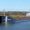
At the end of the last segment I had completed the basic structure of the hull and was proceeding to work out the superstructure. This began, as with the rest of the model, with a careful examination of the photographs of the ship. Fortunately there were a few images of high resolution like this one of the entire ship.
Once enlarged I got a good, if a little fuzzy, picture of the 5 decks and deck houses of the superstructure. I was able to tease out some sense of the complex shapes of the various decks and overhangs. Porthole, door, and stairway locations can be seen, as well as the fact that the top deck house is taller than all the others.
In this slightly clearer image I could start the actual analysis of the dimensions and relationships of the shapes that can be seen. I started with the assumption that the original superstructure footprint had been retained, which is the lowest deck house with the curved fillets on either side. Then, when the hull was widened by 8 feet on each side, some changes were made. The supports for the lifeboat davits had to be built out and supported by pillars reaching to the outer edge of the deck. There is an overhang to the right of the lifeboat that extends to the new deck edge and is supported by three diagonal braces. The bridge wings had to be extended, and a number of other small details all had to be changed.
These images and analysis was integrated with the information from the overhead photos of the ship taken during the incident and rescue, such as this one from just after the recapture.
The image was enlarged and straightened out to give a top view that could be worked with. Always being aware that the image is not precisely taken from directly overhead, I could make out many more details, such as the stairways marked with the red arrows. Hours of staring at these images, individually and collectively, were needed to determine what the various elements and details were. I am still not 100% sure of all of them, and even where I am sure of the shape of things, I am not sure of their purpose. But since this is for the US Merchant Marine Academy, it is good enough for government work.
Other images which were not full pictures of the decks and deck houses also informed a number of details of railings, stairways, overhangs, supports, etc. Here, for example, is one of the Marines taking control of the ship. I would not have seen the tall ventilator/filter under the stairs at the side of the bridge except for this picture.
So, taking all the information in hand, I laid out the shape of the lowest deck house over the top image.
Using this as my basic starting point I laid on the shapes of the stairway platforms and lifeboat davit supports to the first level. Then using the relationships seen in the photos, I drew on the shapes of the second and third decks, deck houses, and overhangs in contrasting colors, giving this image.
Based on these drawings I cut ½” planks of basswood to the shapes of the deck houses (less 0.04” all around) and sheathed them with 0.02” styrene (restoring the full sizes). The decks were cut to the full size of the deck houses and painted grey before being edged with styrene. This gave a pleasing delineation to the decks, which can be seen in the photos. The edges extended just a bit above the deck level, making a lip that anchored the photoetched railings when they were added later. Portholes are the brass dollhouse electric circuit pieces, while the handrails are 0.015” round rod. Here the superstructure stack is about half done, with all the upper details still to be done.
Here is an enlarged shot of some of the details. Notice the diagonal supports for the overhangs of the second deck and bridge wing. The railings and stairways are photoetched brass from Gold Medal Models’ ocean liner set. It is expensive, but makes for a very convincing impression when painted, folded and installed.
The railings come in long frets four scale feet tall (1/4”) with horizontal rails numbering from one to five to be used as needed. The photos of the ship show that the railings mostly have three rails, so these were the frets that were used. They were spray painted gloss white before being cut apart. Unfortunately the paint was a bit brittle, so it chipped off when bent, as can be seen in the last photo, but that was easily touched up later.
The stairways come as part of a larger fret with hooks, steering wheels, etc. They have a central length of steps flanked by angled wings for the side railings. They come in three different lengths. Mostly the middle length was used, but occasionally the short or long ones were needed for a particular location. Small adjustments to length were made by trimming the bottom of the stairways.
The basic stairway is made by bending up the wings of the piece to form the railings at either side of the steps (left image). But this is meant for use on the ocean liners, so it is wider and less steep than the stairways on merchant ships. To make them steeper the railings are pressed down towards the steps till the supporting posts are vertical when the stairs are at the steeper angle (middle image). Where the stairs had to be narrow, one side railing and some of the width of the steps was cut off and the stairs supported by an added strip of styrene (right image).
Work continued on the superstructure with detail added as they were identified in the photos. Note the cross supports between the lower and upper bridge wings and the fact that the front facing of the upper bride wing is taller at the bridge house than it is at the outer end. The funnel has now been sheathed and is set in place so I could determine the location and size of the many details on the upper decks.
While this analysis and work on the superstructure continued I was also starting to puzzle out the size and shape of the 96 containers that had to be installed on deck, and how to build them in a reasonably efficient manner. This will be the topic of the next segment.
Till then, may your health be better than mine.
Dan
-
 shipmodel got a reaction from Keith Black in Bristol Pilot Cutter by michael mott - 1/8 scale - POF
Michael -
I also missed your post about your hand injury, my friend.
Glad to see you back, and hope that your recovery was complete and satisfactory.
Be well
Dan
-
shipmodel got a reaction from GrandpaPhil in SS Mayaguez c.1975 by shipmodel - FINISHED - scale 1/16" = 1' (1:192) - Dan Pariser
Hi again to all –
Thanks as always for the likes and comments. I hope everyone has had a good summer and we are getting back to the workbench and computer, as I am.
Thanks also to all who asked about my health problems. They are all getting better, slowly, and in any event were small compared to some of those suffered by other friends in the MSW family. My best wishes for speedy and complete recoveries to all.
When I left off last segment the 96 containers had all been built and detailed and set on deck. But they have to be supported on leveling trestles and supports that raise them to a height where the cranes can move them around. As before, there are no plans of these structures, so I had to rely on somewhat fuzzy photos. The interpretations of these were some of the most difficult of the build, and I spent any number of hours staring at the images, changing lighting and contrast, till I had a pretty good idea of how they worked. Here are some of the better images with arrows pointing to the several elements:
After all this studying, and keeping in mind what I was capable of building, I came up with this rough cross-section sketch of the various components and how they would sit on or attach to each other:
The first element to build was the support trestle. To get the right taper and curve to the vertical piece of the I-beam I clipped pieces of card stock to small wood blocks and set them on the fore and aft decks. With careful measuring and trimming I matched the lower edge to the deck curve. Then using a small line level I laid out and marked the top edge so it was horizontal and parallel with the waterline. The final task was to adjust that horizontal line to a level where the final height of the containers would match the look seen in the photos. Since the container supports had not been built, nor the final structure of the container blocks, this was a bit of an informed guess, but I think it came out OK in the end.
With the shape of the vertical piece determined I cut out the tapered piece from 0.03” (.75mm for the metrically minded) styrene. The same plastic gave me a wide bottom piece and a narrower top piece for the trestle I-beam.
The tapered piece was laid on a wood sheet of a thickness that supported it at half the height of the lower piece. Using small pieces of wood to hold the plastic pieces against each other they were glued along the joint with thin plastic cement, which essentially softens and welds the pieces to each other. Note that where possible the pieces are cut oversize to be trimmed after gluing.
Locations for the trestle web pieces were marked out along the length of the trestle at 3/16” (3 foot in scale) intervals. This may be a bit wide, but it does match the look from the photos. The web pieces were also cut long and extended past the top edge of the vertical piece. Once they were all glued on solidly the tops were cut to match the edge of the piece. Doing it in this sequence meant that I never had to cut and fit the pieces individually to their different lengths.
After trimming the web pieces the narrower top piece was glued on using small wood blocks as before.
Now the outer edges of the web pieces could be cut to the taper to match the wider lower piece and the narrower top piece. This is the final look of the leveling trestles, which matches the cross-section sketch pretty closely.
The crane guide rails were attached to the tops of the leveling trestles and they were set on deck to check their appearance.
Plastic I-beams of various heights were attached to the trestles so the port and starboard ones would be parallel with each other. The beams had to be cut to a length that would allow for the thicknesses of the future container supports and the sizes of the containers themselves inside the crane guide rails. A lot of trial and error went into this, and a fair amount of cursing, because the tolerances were so small. However finally a satisfactory dimension was achieved and the I-beams were all cut to this length. After gluing, the trestle assembly was painted dark bronze. I don’t have any references for this choice, but it does set them off from the deck and the containers, and the color is not unknown as a rust resistant coating.
A final check with the line level confirmed that everything was up to spec, which was followed by a big sigh and a bigger glass of bourbon.
The forward trestles were built in the same manner. Note that there is no beam across the forward end of the forward trestles. The photos show that this area is open, so that is how it was built. The two sets were temporarily laid on deck to see if anything looked wrong or out of scale. Fortunately, I was happy with the results so the pieces were removed and set aside for later use.
While this was going on, the final detailing of the superstructure, as well as the bow and stern decks, was also proceeding. These will be covered in the next installment.
Until then, stay safe and well.
Dan
-
 shipmodel got a reaction from mtaylor in SS Mayaguez c.1975 by shipmodel - FINISHED - scale 1/16" = 1' (1:192) - Dan Pariser
Hi again to all –
Thanks as always for the likes and comments. I hope everyone has had a good summer and we are getting back to the workbench and computer, as I am.
Thanks also to all who asked about my health problems. They are all getting better, slowly, and in any event were small compared to some of those suffered by other friends in the MSW family. My best wishes for speedy and complete recoveries to all.
When I left off last segment the 96 containers had all been built and detailed and set on deck. But they have to be supported on leveling trestles and supports that raise them to a height where the cranes can move them around. As before, there are no plans of these structures, so I had to rely on somewhat fuzzy photos. The interpretations of these were some of the most difficult of the build, and I spent any number of hours staring at the images, changing lighting and contrast, till I had a pretty good idea of how they worked. Here are some of the better images with arrows pointing to the several elements:
After all this studying, and keeping in mind what I was capable of building, I came up with this rough cross-section sketch of the various components and how they would sit on or attach to each other:
The first element to build was the support trestle. To get the right taper and curve to the vertical piece of the I-beam I clipped pieces of card stock to small wood blocks and set them on the fore and aft decks. With careful measuring and trimming I matched the lower edge to the deck curve. Then using a small line level I laid out and marked the top edge so it was horizontal and parallel with the waterline. The final task was to adjust that horizontal line to a level where the final height of the containers would match the look seen in the photos. Since the container supports had not been built, nor the final structure of the container blocks, this was a bit of an informed guess, but I think it came out OK in the end.
With the shape of the vertical piece determined I cut out the tapered piece from 0.03” (.75mm for the metrically minded) styrene. The same plastic gave me a wide bottom piece and a narrower top piece for the trestle I-beam.
The tapered piece was laid on a wood sheet of a thickness that supported it at half the height of the lower piece. Using small pieces of wood to hold the plastic pieces against each other they were glued along the joint with thin plastic cement, which essentially softens and welds the pieces to each other. Note that where possible the pieces are cut oversize to be trimmed after gluing.
Locations for the trestle web pieces were marked out along the length of the trestle at 3/16” (3 foot in scale) intervals. This may be a bit wide, but it does match the look from the photos. The web pieces were also cut long and extended past the top edge of the vertical piece. Once they were all glued on solidly the tops were cut to match the edge of the piece. Doing it in this sequence meant that I never had to cut and fit the pieces individually to their different lengths.
After trimming the web pieces the narrower top piece was glued on using small wood blocks as before.
Now the outer edges of the web pieces could be cut to the taper to match the wider lower piece and the narrower top piece. This is the final look of the leveling trestles, which matches the cross-section sketch pretty closely.
The crane guide rails were attached to the tops of the leveling trestles and they were set on deck to check their appearance.
Plastic I-beams of various heights were attached to the trestles so the port and starboard ones would be parallel with each other. The beams had to be cut to a length that would allow for the thicknesses of the future container supports and the sizes of the containers themselves inside the crane guide rails. A lot of trial and error went into this, and a fair amount of cursing, because the tolerances were so small. However finally a satisfactory dimension was achieved and the I-beams were all cut to this length. After gluing, the trestle assembly was painted dark bronze. I don’t have any references for this choice, but it does set them off from the deck and the containers, and the color is not unknown as a rust resistant coating.
A final check with the line level confirmed that everything was up to spec, which was followed by a big sigh and a bigger glass of bourbon.
The forward trestles were built in the same manner. Note that there is no beam across the forward end of the forward trestles. The photos show that this area is open, so that is how it was built. The two sets were temporarily laid on deck to see if anything looked wrong or out of scale. Fortunately, I was happy with the results so the pieces were removed and set aside for later use.
While this was going on, the final detailing of the superstructure, as well as the bow and stern decks, was also proceeding. These will be covered in the next installment.
Until then, stay safe and well.
Dan