
HOLIDAY DONATION DRIVE - SUPPORT MSW - DO YOUR PART TO KEEP THIS GREAT FORUM GOING! (83 donations so far out of 49,000 members - C'mon guys!)
×


Dr PR
-
Posts
2,439 -
Joined
-
Last visited
Content Type
Profiles
Forums
Gallery
Events
Everything posted by Dr PR
-
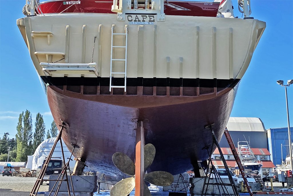
 Here is another "sea tale" about the Cape - and minesweepers in general. We went out once while I was aboard to sweep magnetic mines. Our forward engine room had two large generators to produce current for our "magtail." This was a two wire cable - the wires were 1 inch (25.4 mm) diameter copper cables (probably the most valuable part of the vessel) - that was strung out behind the ship. It had two electrodes that were spaced 50-100 feet apart. The current from the generators was fed to these electrodes and then flowed through sea water. The current through the water generated a large magnetic field several hundred yards behind the ship. This magnetic field simulated the change in the Earth's magnetic field that a large iron ship would create, and this would detonate mines that had magnetic sensors. But the minesweeper itself should create no change in the Earth's magnetic field if it wasn't to be blown up. As I have explained earlier, our engines and other large metal objects were all made of non-magnetic materials. We had a few magnetic things aboard, like the magnetic compass, but these things had degaussing systems to cancel the magnetism. While we were in port (most of the time for the Cape) we had all sorts of magnetic items on board. Metal office chairs, typewriters, some tools, personal belongings and such. When we went out to sweep magnetic mines all of these things had to be off loaded and stored in a locker on shore. It was a real pain in the posterior to get all of these things off the ship and in storage, and then to have to move them all back aboard after the sweeping exercise. We went to San Diego for a yard period (when they screwed up one of our engines) and afterward passed through the Navy's degaussing station off Point Loma. This was a series of under water "metal detectors" off to the side of the channel into harbor. We made several passes through these and adjusted our degaussing system to cancel all magnetic fields from the ship. However, there was one magnetic field we couldn't cancel. As we passed through the array yet one more time the station ashore radioed us and said there was a metallic object in the bilges and gave us a frame number. Our enginemen pulled up the deck plates and looked around in the bilges. Sure enough - we found a small crescent wrench one of the yard workers had dropped, right where the degaussing station operators said it would be! That really impressed me! After losing the wrench over the side the ship had no magnetic signature.
- 464 replies
-
- 9
-

-

-
- minesweeper
- Cape
- (and 1 more)
-
Mark, Where did your father live - Medford? My dad was a teetotaler too, as was my mom. I didn't start drinking alcohol until I joined the Navy. I guess without the lemon it is just called "brandy and ginger ale". At least that's what Alec Guiness asked for in "Tinker, Taylor ..." Add the lemon and it's a "horse neck." Without the brandy I think I would call it a "pony neck."
- 464 replies
-
- 2
-
-
- minesweeper
- Cape
- (and 1 more)
-
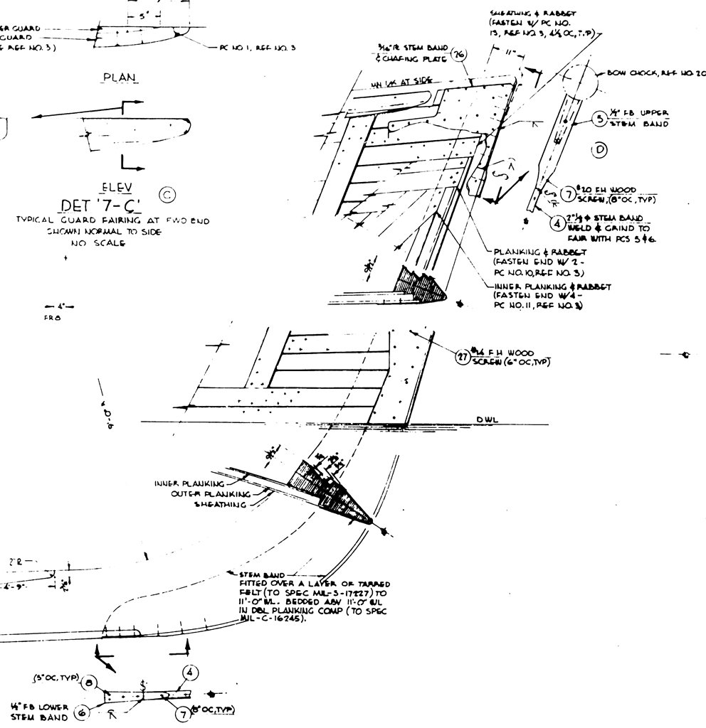
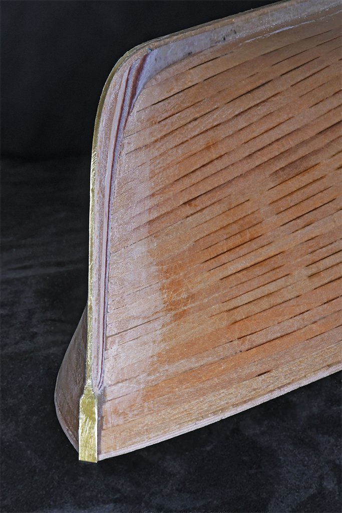
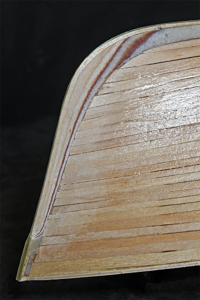
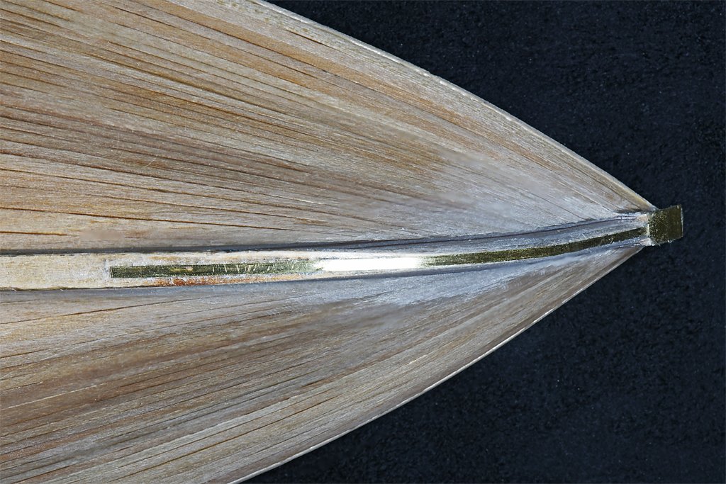
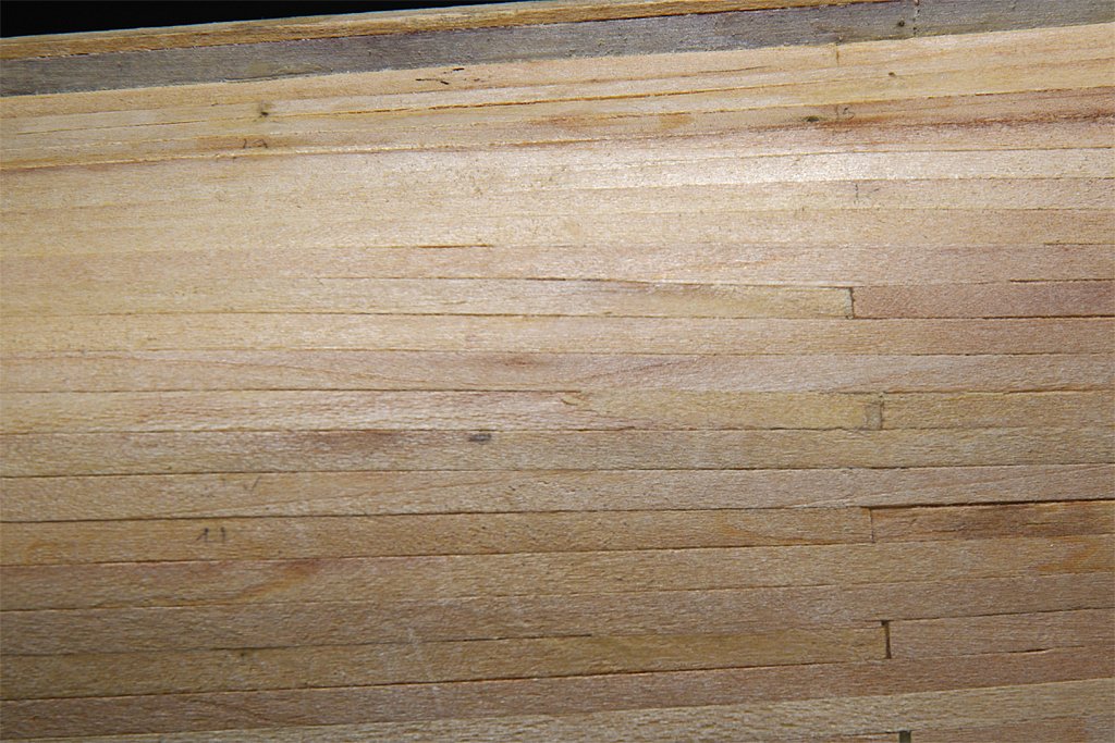
Thanks, John! One of the tasks for finishing the hull was to fair the stem. In the blueprint (left) the stem is shaped to continue the angle of the planking right up to a metal stem band running down the front of the stem. The two cross sections shown in the drawing show how this is supposed to look. I have been a bit skeptical that this would work out correctly on the model because the angle at the bow changes from the keel up to the top. Just looking at the planking and the thickness of the keel piece I wasn't sure I could get the proper angles. However, when I made the keel/center piece I did put the rabbet line where it was shown on the blueprint. And to my surprise the angles did come out almost perfect! Here are some photos, although it is difficult to show the angles in the pictures. The metal stem band is a 0.050 inch (1.27 mm) brass strip from the foot of the bow up to where the stem widens to the 3/16 inch (4.76 mm) width of the plywood keel/center piece at the top. The different layers of the plywood are different colors, and the colored stripes were very helpful for filing and scraping the piece to a uniform taper. You really can't see how the stem fairs into the hull at the same angles as the planking, but the surfaces are very smooth to the touch where the planks and the plywood meet. This came out a lot better than I thought it would!
- 464 replies
-
- 8
-
-
- minesweeper
- Cape
- (and 1 more)
-
John, Wives are more important than models, so take care of her. Enjoy the holidays. The model will be waiting when you have the time.
-
I only had six small cannons and pivot gun on my topsail schooner build and that was enough for me. I cannot imagine rigging dozens of cannons as are found on some of the higher rates! I think rigging cannons is my least favorite part of ship model building.
-
I agree about the stay over the metal band. It would be much more common to lay the stay over the shrouds. However, I found at least a half dozen drawings showing the forestay located higher up on the mast head, held in place by a thumb cleat on the back side of the mast. I also found one instance where the forestay was located very high just below the mast top, with a lashing looping over the top to secure the stay. So there was a lot of variation in the positioning of the stays. It is not impossible that the stay did loop over the mast band, but I think there would have been some additional material between the stay and the band to prevent chafing. The stays seem to have been located higher up in order to avoid interference with rigging for the fore course yard. If the mast had an extreme rake the stay would lay against the yard if it (the stay) was just looped over the shrouds. I had this problem with the rigging on my topsail schooner build. https://modelshipworld.com/topic/19611-albatros-by-dr-pr-mantua-scale-148-revenue-cutter-kitbash-about-1815/?do=findComment&comment=1020038 https://modelshipworld.com/topic/19611-albatros-by-dr-pr-mantua-scale-148-revenue-cutter-kitbash-about-1815/?do=findComment&comment=1029254
-
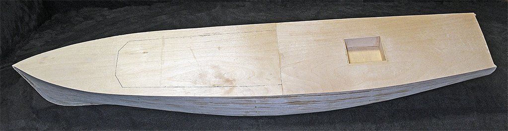
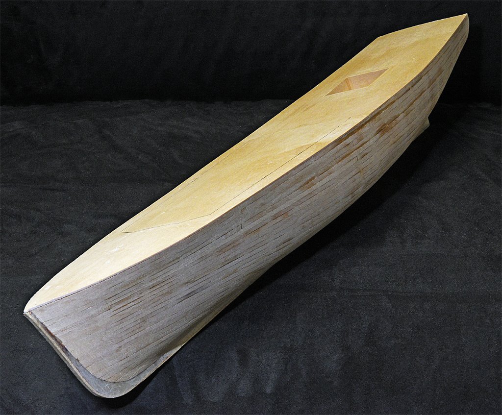
I have sanded the hull with 80 grit followed by 220 grit to knock down some of the high points and remove any of the epoxy that made it through to the surface. Now it is ready for the first coat of sealer. I will use an acrylic sealer. There are still some significant "divots" to fill. I have also glued on the two halves of the main deck. There is still a lot to do on the hull. The biggest project will be making the stern frame that carries the propeller shaft and provides the lower pivot for the rudder. I'm not sure how I will do that.
- 464 replies
-
- 10
-
-
- minesweeper
- Cape
- (and 1 more)
-
Beautiful work Valeriy! You are on a roll!
-
I solved the missing tool problem long ago. I have a tool box and unused tools go into the box. However, it is last in first out (LIFO) stack. So the last tool I used is on top of the stack (pile) of tools in the box. If I haven't used a tool in some time it is on the bottom of the pile. But I know where it is - I just have to dig it out from under all the other tools.
-
If you are a glutton for punishment you could try make a "cut" splice like what was actually used on the cascobel, https://modelshipworld.com/topic/19611-albatros-by-dr-pr-mantua-scale-148-revenue-cutter-kitbash-about-1815/?do=findComment&comment=650378
-
The "projections" on the mast bands are eyes or metal rings for the gaff peak halliard rigging to attach to (Petersson page 33). Look at some of the other cutter builds on the Forum to see what others have done for the mast cap. It could be a metal band that fits round the square main mast top and the round topmast. Or it could be wood with a metal band around it. Both the sheet and the clue line connect to the clue (lower outboard corner of the sail). They are not the same line. However, if the sail isn't rigged the ends of the clue line and sheet will be hooked/tied together in preparation for adding the sail. I think this is what he shows on page 29 with the "V" in the clue line from the topsail yard down to the end of the sheet and back up through the block under the topsail yard and then down to belay on deck. The sheet hauls the clue of the sail out to the end of the yard. The sheet passes through the inboard sheave in the yard arm. The clue line hauls the clue of the sail up when reefing the sail. I don't know why he shows two sheaves on the yard arm. He only shows one being used - but he doesn't show all of the sails rigged. If the lifts were doubled the outer sheave could be part of the tackle. Doubled means passing through two blocks as part of a tackle. It was common to crate the lift tackle this was so there was less clutter at the deck level (instead of putting the tackle on deck at the base of the mast). On page 28 he shows a "fiddle" block (block shaped like the body of a violin with two singe sheaves) at the mast top. The lower yard passes through the upper sheave and is shown tied to the yard arm. It could be that the second sheave in the fiddle block and the inner sheave at the yard arm made up a type of luff tackle with the fixed end of the lift tied to the tard arm and the line passing through the upper sheave of the fiddle block, back to the inner sheave on the yard arm, back up to the lower sheave in the fiddle block and down to the deck. This seems to be an awkward arrangement for the line passing through the inner sheave on the yard arm. I suppose the inner sheave on the yard arm might be for a reef tackle on a fore course (main square sail) - he doesn't show rigging for a reef tackle in the cutter section (see page 105 for the reef tackle on a schooner's topsail). The lower sheave on the fiddle block could be part of the reef tackle running from a cringle on the outer edge of the course, up through the inner sheave in the yard arm, up to the lower sheave in the fiddle block and then down to the deck. I would guess this is the most likely explanation for the two sheaves in the yard arms. However, I am just guessing. I looked at several references and found no examples of tard arms with two sheaves - blocks attached to the yard arms were more common. Maybe someone more familiar with Engkish cutters will provide the answer.
-
Jeff, It is a static model. The first plank on bulkhead kit I built (Santa Maria, 1969) developed cracks between the planks a few years later. I spent a lot of time getting that hull perfectly smooth and the cracks really annoyed me! I suspect this was the result of the wood swelling and shrinking as a result of changes in humidity. With dry wood the change isn't much - just a percent or two if I recall correctly - but enough to crack the paint on the hull. The same thing happened on the second plank on bulkhead kit I built (Freya, 1970s). On the next hull I built (Albatross) I painted the interior with a clear epoxy "paint" that flying model builders used to seal balsa engine mounts to prevent the wood from absorbing fuel. Now, 40 years later, that hull has no cracks. The epoxy also acts something like the inner layer on a double planked hull. It provides support for the planks between bulkheads. On earlier models I had some problems with planks bending between bulkheads when under pressure from sanding. This can make it difficult to get a really smooth surface without edges of one plank rising above the neighbor a bit. With the epoxy gluing everything together this cannot happen.
- 464 replies
-
- 6
-
-
- minesweeper
- Cape
- (and 1 more)
-
MArk, Did your father (or anyone else) call it a horse neck?
- 464 replies
-
- 2
-
-
- minesweeper
- Cape
- (and 1 more)
-
Chain-nosed pliers. Used for making chains. I have one that I use for making eye bolts, ring bolts and such. Very useful when you need it!
-
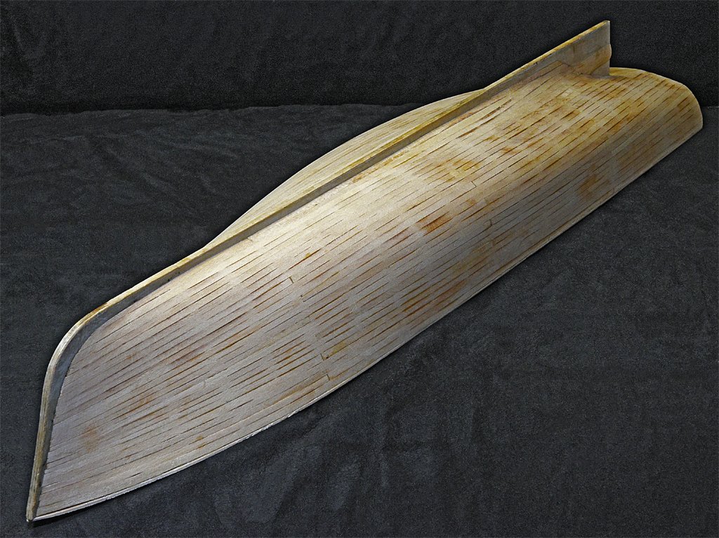
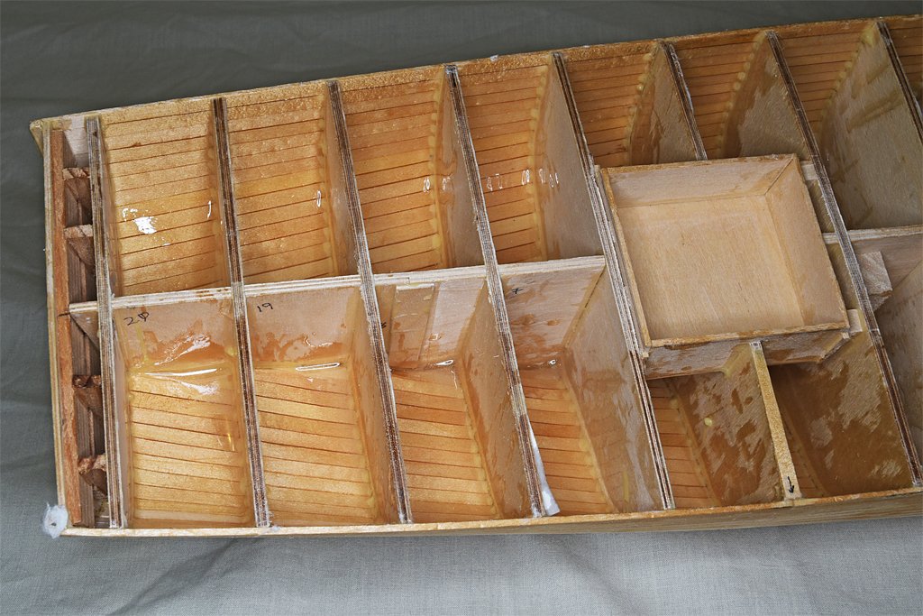
John, It is almost like making sails or rigging ratlines - it seems to just go on and on ... Today I coated the interior with epoxy to seal all the cracks and bond everything together securely. You can see the shine of the hardened epoxy in the photo at left. I applied a heavy coat to be sure all the seams are glued tight. Since it is a two-part epoxy mix with a limited working time (15-25 minutes) I slopped it on pretty quickly. It is a bit messy, but it is on the inside where it won't be seen. In the photo at the right you can see how the thin epoxy flowed into the cracks between the planks and absorbed into the wood. Where the planks were glued to the bulkheads with SIG Bond glue the epoxy didn't flow. At at the very stern, aft of the last bulkhead, the space between that bulkhead and the transom did not get any epoxy. This shows clearly how the epoxy fills the cracks where it is applied. Keep in mind that I beveled all of the planks to fit the neighboring planks and jammed them together pretty hard while installing the planks. Even so the thin epoxy flowed into and through the joints. They are all glued together securely now! I spent a day or two filling all the noticeable gaps between planks (there were some about 0.010 inch (0.25 mm) wide in a few places and I filled them with wood shavings and cement. But there were a couple I had missed and a bit of epoxy flowed through. I was counting on that. There are no unfilled gaps between planks on the hull now! It will be rock solid! I'll give it a day or two before I start sanding the hull smooth. With all the planks bonded together with the epoxy I don't have to worry about any planks flexing under the pressure of sanding and causing problems getting a smooth hull. I also have to shape the stem to match the curve of the planks so there is a fairly sharp cutwater on the bow. I think any thin clear epoxy will do for sealing the interior of a hull. I used a product intended for covering counter tops, tables and such. For those applications you pour it on and allow it to flow into a flat film 1/8 to 1/4 inch (3.2 to 6.4 mm) thick. After it was mixed I used a small spatula to "spoon" the epoxy on the the planks and then spread it around. It was about as runny as maple syrup at first so it flowed evenly over the planks. I pushed some up onto the bulkheads to get a bond between the planks and bulkheads (in addition to the wood glue used when installing the planks). The thickness of the epoxy is only about half a millimeter thick (0.020 inch) since I don't need a nice smooth surface. I occasionally rotated the hull back and forth to get the epoxy to flow over the planks and not pool in the bottom along the keel. After about 20-25 minutes it had thickened so it didn't run and I could just leave the hull upright. I did have one concern before I started. I have used many different two-part epoxy and urethane mixtures, and some generate a lot of heat. I mixed up at least half a cup (120 ml) and with some epoxies that amount would get quite warm. Since the aliphatic resin glue I used when installing the planks will soften when heated, I worried that the heat from the epoxy would unglue everything! But there was no problem - the container I mixed the epoxy in just barely got warm.
- 464 replies
-
- 8
-
-
- minesweeper
- Cape
- (and 1 more)
-
Measurements? Proportions?? I just squeeze a slice of lemon into a cocktail glass or tumbler, put the lemon in the bottom, add "some" Brandy, and fill with ginger ale. After a few of these you won't care about measurements! OK, I measured the glass and it is 250 ml or 1 cup. The shot glass is 1 oz (29 ml). I use a relatively cheap French VSOP brandy for mixing, and save the good Cognac for drinking straight.
- 464 replies
-
- 3
-
-
-
- minesweeper
- Cape
- (and 1 more)
-
Tony, You can get useful dimensional information from 2D photos, but you will have to combine all of the 2D information to make the 3D model. First, al the dimensions in a picture are relative to all other dimensions. You may not know the actual dimensions in feet/meters, but you can calculate the relative dimensions of objects. I often work in CAD without defining any units of measurement. Everything is done in "drawing units." After the drawing is done I can set the relationship between drawing units and real world units and the drawing can be in feet, meters, furlongs, parsecs - whatever. So the actual dimensions are not necessary. You can build the entire model from relative dimensions gleaned from photos. Others here have pointed out problems with 2D photos like view angle and distance. If the object in the photo is not exactly perpendicular to the line of sight more distant objects will be relatively small and closer objects proportionately larger. This will be the major problem in determining dimensions of objects in the photo. However, there are a few tricks you can use to overcome this issue. Look for a "standard dimension" in the picture. For example, in most of the 20th century the US Navy had a standard life rail construction on almost all ships. The rails had three vertical bars spaced from the deck 15, 27 and 39 inches, with stanchion height of 42 inches. Since nearly all ships had life rails somewhere, if you have a photo of a US Navy ship from that period you have a built in vertical "ruler" to determine the height of other objects by comparison to the railings. I call this "photoguesstimation." However, the vertical spacing of the stanchions does not seem to be a standard dimension, but varies from place to place. Another trick is to assume that similar structures have similar heights. Deck houses on a ship are usually the same height, or multiples of a common overhead height. Portholes are usually one size throughout the ship, and they can give relative height and length information. Vertical ladders are also vertical rulers. Doors are usually some standard size, although there may be several different sizes on a ship. Remember that the designer and builder used some standard units of measurement (feet and inches, meters and centimeters, etc.). When you calculate a dimension and it comes out an odd fraction of a common unit, just round off to the nearest common unit. For example, I noticed that US warships of the mid 20th century were designed in multiples of 1/16 inch. So I just rounded off all photooguestimatios to the nearest 16th. While you can't feed a 2D picture into a CAD program and have it generate a 3D model, you can derive a lot of information from the picture to allow you to make an approximation. If you do this from multiple 2D photos you may be able to determine dimensions for objects that are common to all the photos.
-
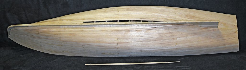
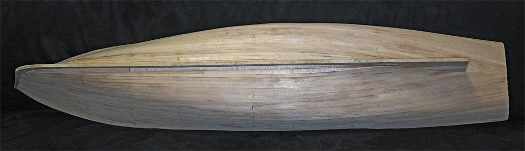
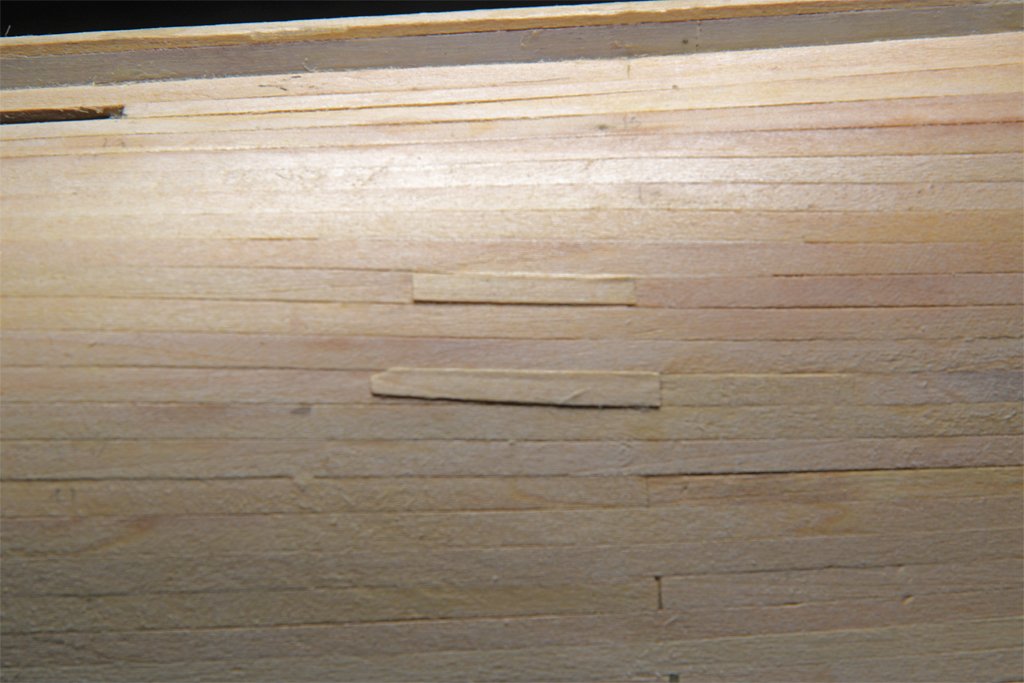
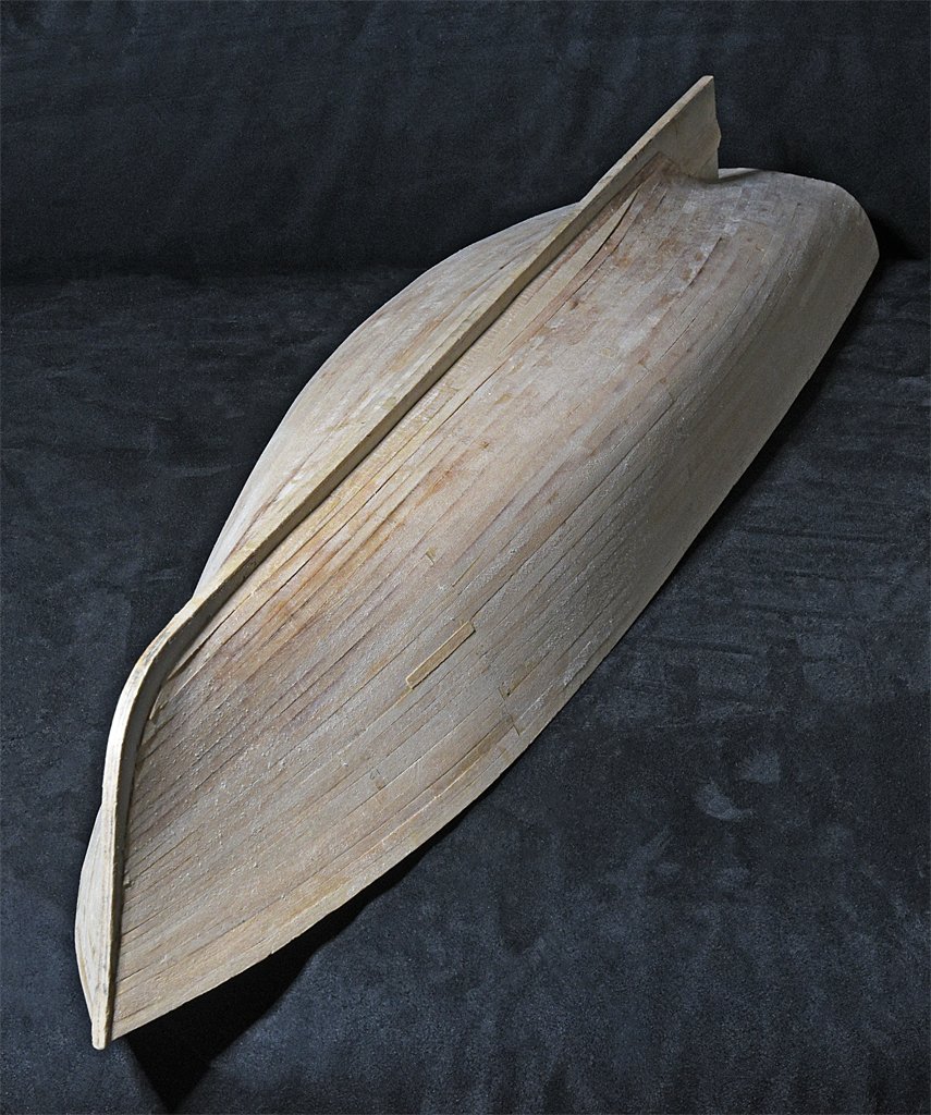
THE LAST PLANK! Here is another view of the planked hull. I have been doing a rough smoothing job with files and scrapers while the glue was setting for the latest planks. I haven't done this for the last two or three planks near the keel so you can see some plank edges standing proud. Now I can get on with a few other tasks to prepare the hull for installing the sub deck. I mentioned earlier that I had a few spots where some of the planks were noticeably thinner than the others, especially at the plank ends. This created some low spots at the butt joints. To solve this problem I used a plane to shave off thin strips of basswood from scrap planks. These I glued into the low spots in the planking (left). After the glue set overnight these patches were sanded/filed down smooth with the surrounding planking (right). Next I will coat the inside of the hull with thin clear epoxy that will soak into the wood and fill gaps between planks and between the planks and the bulkheads. This will produce a rock solid hull that will not gain cracks between the planks over time. After the epoxy sets I will sand the hull smooth and put on a sealer. **** I know many of you celebrate the last plank with your favorite cordial. Well, it's a bit early for tea time here (unless you are still on Daylight Savings Time). But I am celebrating with an orsenek. For those of you who don't speak British that translates into (American) English as "horse neck." It's something I picked up from the Brits in Hong Kong. When the Okie City steamed into HK they would berth us at the pier at HMS Tamar, the British naval station. They tied us up with our Officer's Brow aligned with the door into the base Officers Bar. That was very convenient and friendly of them! The British officers threw a cocktail party in their bar for the OK City officers, and we reciprocated with a dinner in our Wardroom for them. I have always liked ginger ale since I was a kid, and they served horse necks - brandy and ginger ale with a slice (not twist!) of lemon (and no ice!). I had never had one before, and it was delicious - really good ginger ale! I have tried ordering a horse neck at bars here in the US and they have no idea what I am talking about. One bartender thought it was some form of rum and coke or some other awful concoction! But I make a proper orsenek in my house! Cheers!
- 464 replies
-
- 10
-
-

-
- minesweeper
- Cape
- (and 1 more)
-
Funny how fortune smiled on some people. The two guys I went to grade, middle, high school and college with that were drafted out of college were assigned to a radar site in Sausalito, California, across the Golden Gate from San Francisco! Really choice duty!
- 464 replies
-
- 3
-
-
- minesweeper
- Cape
- (and 1 more)
-
Yesterday (Thanksgiving in the United States) a local radio station played Arlo Guthrie's "Alice's Restaurant" a couple of times - it being a Thanksgiving song. And it reminded me of another sea tale, although it is only indirectly related to the USS Cape. But it does tell how/why I ended up in the Navy and on the Cape. I graduated from The University of Arkansas in 1968 with a Bachelor's degree in microbiology. If you recall your American history, the little fracus in Vietnam was at it's height in 1968. While I was in college I had a 1S Student Deferment from the draft, but that was about to end. Our local Draft Board was dead set to allow all eligible young men to have a chance to spill their guts for their country, and had already drafted two of my friends out of college and into the Army. I guess you could say the handwriting was on the wall. So I started looking around for other opportunities. The Air Force had more personnel than they needed, and plenty waiting in line ahead of me. I had already taken two years of compulsory Army ROTC (Reserve Officer's Training Corps) and that was enough of that. I didn't want to be a grenade catcher sleeping in a muddy foxhole. The National Guard was booked up. So that left the Navy. I took the Naval Officer Candidate School (NAVOCS) entrance exam and passed with flying colors. I went to the Navy Recruiter Office in Little Rock, Arkansas, and signed up for Officer Candidate School. But before they would take me I had to have a physical exam at the induction center where the recruiter's office was. I was the only person going through the medical facility that afternoon, and they gave me a long and thorough exam. For example, they took my blood pressure five times (walking, lying down, after 30 pushups, sitting and standing). I passed the physical and went down to the Recruiter's office to sign the papers. I was in the Navy, although I had never seen a ship or an ocean. A couple days later I received my draft notice from the Army! I called the Navy Recruiter and asked "Interrogative Whisky Tango Foxtrot, over?" He said not to worry, the paperwork had just passed each other in the mail (this was before the Internet, cell phones and video games). But he said it would cause them a lot of paperwork to try to cancel my appointment for the pre-induction physical, so he asked me to just go through it again. "They can't have you" he said, "You're our boy!" If you have ever seen the Alice's Restaurant movie, or if you were drafted, you probably recall the induction physical. "Turn your head and cough." And like Arlo said, we were inspected, detected and selected, and they were leaving no part untouched. This was the same place, and the same people who gave me the Navy OCS physical. But this time I was in a line with hundreds of other guys shuffling along in my skivies. When we went into the office where they took our blood pressure the line didn't stop moving. It was one quick check and we were on our way. The Army would take anyone with one good arm, one good leg, one good eye and still breathing. After the physical we had to take the Army entrance exam (on the cold benches like in the movie). We had an hour to answer 100 questions. I had just finished five years of intensive test taking and I breezed through the test in 15 minutes. I looked around and everyone else was scratching their heads in intense concentration. This was a bad sign - I learned in college if a test seemed too easy I was missing something. But I rechecked my answers and went up to the sergeant at the desk up front (I swear it was the same guy in the movie - or maybe all sergeants just look alike). "What do you want" he asked? "I'm finished" I said. He took the test and checked my answers. Then he looked up in surprise and said "Yours is the highest grade anyone has ever made on this test!" He said I could leave, so I got dressed and started out of the building. Well, the Navy Recruiter's office was on my way out, and had a large window facing into the hallway. I waved at the recruiter as I passed and then it hit me! I realized what I was missing and almost doubled over with laughter. I am probably the only guy who ever tried to pass the draft test! And that is how I dodged the draft. I graduated from Naval Officer Candidates School and was assigned to the Cape by the Bureau of Personnel (BUPERS). **** I hope you all had a happy Thanksgiving (or whatever day you had where you live)!
- 464 replies
-
- 8
-
-

-
- minesweeper
- Cape
- (and 1 more)
-
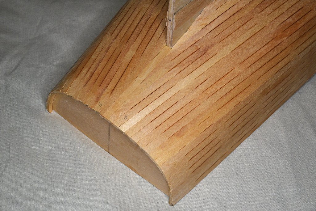
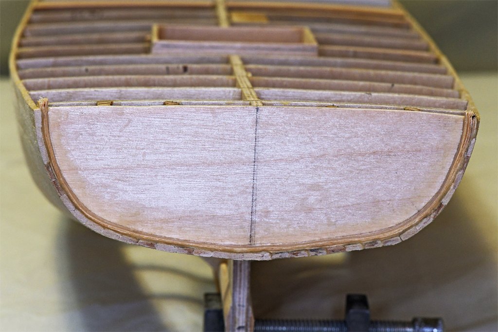
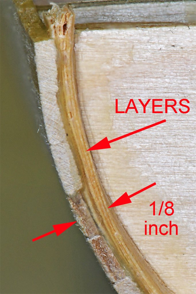
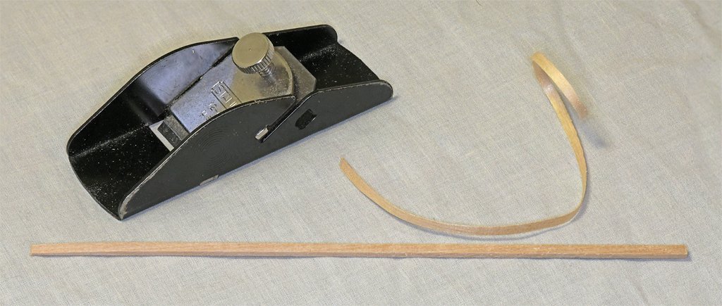
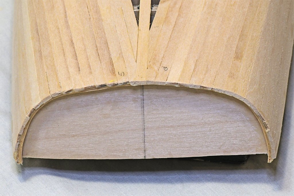
More planking done. Now about 2/3 finished. The planking has come together at the stern so I can start thinking about work on the transom. I have sanded the ends of the planks to about 3/16 inch (4.8 mm) aft of the transom. Around the edge of the transom is a "guard" (what it is called in the blueprints), that should be 1/8 inch (2.3 mm) high off the transom. Here is a photo of the current day Cape stern (thanks to the owner Austin Cox). You can see this guard around the stern. Here is another photo showing the guard on the model. The guard should be 1/8 inch (2.3 mm) wide. The planks are 1/16 inch (1.6 mm) thick, so I needed to add another 1/16 inch to the inside. To do this I glued five successive layers of basswood shavings around the inside of the planking. The shavings are about 0.008 inch (0.2 mm) thick. The glue adds to the thickness to build up to slightly more than the needed thickness. The stern also had the vertical "guard" boards shown in the ship's photo, but in a bit different configuration. It has been modified a few times since it was a Navy vessel. This picture shows the layers of shavings glued around the inside of the planking. After the glue has set a few days I will sand the ends of the planks down to the proper height. Then I will sand the shavings to a better shape and add a plank across the bottom as is shown in the photo of the ship's stern. I suspect a bit of putty will be necessary to finish the job. I made the shavings with my trusty 3 1/2 inch (89 mm) Stanley 12-101 plane. I have had it for decades (it has U. S. A. stamped on the side) so it is probably an antique by now. I selected a 1/8 x 1/8 inch basswood stick and shaved several strips from it. The laminated shavings are the right height for the guard.
- 464 replies
-
- 9
-
-
- minesweeper
- Cape
- (and 1 more)
-
On the ships I served on the gratings were raised above the deck enough to allow water to flow under them. An open cockpit on a small vessel like the schooner would occasionally be awash in heavy seas. so the raised grating puts the helmsman's feet a bit above the sloshing water. However, this keeps the feet only relatively "dry." On the 112 foot minesweeper I was on the open bridge was 15 feet (4 1/2 meters) above the water line. In heavy weather waves occasionally broke over the bridge, We had a raised grating but it didn't keep us dry. Sometimes we had 6 inches (15 cm) of water sloshing across the deck. The grating only allowed the water to drain off our feet some of the time.
-
George, Nice work. Research and figuring out how to make and rig things takes much longer than actually doing the work. Also, I find that even after the research I may still be trying to decide which of several possible ways to do the job I will choose. One of my favorite sayings is "Maybe it is a good thing I am slow because I might be going in the wrong direction."
-
I have been under the impression that the jib boom outhaul was not permanently rigged, but was set up only when the boom was to be hauled out. I recall one example where the end of the outhaul was belayed to a cleat on the bowsprit inside the bulwarks. It could be belayed to a timber head or knight head. Since it was temporarily rigged the belaying point could be anything convenient. It would be rigged only while the jib boom crupper was being put in place.
-
Tony, To answer your original question - no! There are programs that can generate a rough 3D model of something from photos. Multiple images are taken from different positions all around the object. Then with a little prodding the program creates a crude image, often "painting" the original photos onto flat surfaces. I have seen this done to make 3D models of buildings. But I don't know how well this would work for irregular or curved surfaces.