


Dr PR
-
Posts
2,472 -
Joined
-
Last visited
Content Type
Profiles
Forums
Gallery
Events
Everything posted by Dr PR
-
 Funny how fortune smiled on some people. The two guys I went to grade, middle, high school and college with that were drafted out of college were assigned to a radar site in Sausalito, California, across the Golden Gate from San Francisco! Really choice duty!
- 492 replies
-
- 3
-

-
- minesweeper
- Cape
- (and 1 more)
-
Yesterday (Thanksgiving in the United States) a local radio station played Arlo Guthrie's "Alice's Restaurant" a couple of times - it being a Thanksgiving song. And it reminded me of another sea tale, although it is only indirectly related to the USS Cape. But it does tell how/why I ended up in the Navy and on the Cape. I graduated from The University of Arkansas in 1968 with a Bachelor's degree in microbiology. If you recall your American history, the little fracus in Vietnam was at it's height in 1968. While I was in college I had a 1S Student Deferment from the draft, but that was about to end. Our local Draft Board was dead set to allow all eligible young men to have a chance to spill their guts for their country, and had already drafted two of my friends out of college and into the Army. I guess you could say the handwriting was on the wall. So I started looking around for other opportunities. The Air Force had more personnel than they needed, and plenty waiting in line ahead of me. I had already taken two years of compulsory Army ROTC (Reserve Officer's Training Corps) and that was enough of that. I didn't want to be a grenade catcher sleeping in a muddy foxhole. The National Guard was booked up. So that left the Navy. I took the Naval Officer Candidate School (NAVOCS) entrance exam and passed with flying colors. I went to the Navy Recruiter Office in Little Rock, Arkansas, and signed up for Officer Candidate School. But before they would take me I had to have a physical exam at the induction center where the recruiter's office was. I was the only person going through the medical facility that afternoon, and they gave me a long and thorough exam. For example, they took my blood pressure five times (walking, lying down, after 30 pushups, sitting and standing). I passed the physical and went down to the Recruiter's office to sign the papers. I was in the Navy, although I had never seen a ship or an ocean. A couple days later I received my draft notice from the Army! I called the Navy Recruiter and asked "Interrogative Whisky Tango Foxtrot, over?" He said not to worry, the paperwork had just passed each other in the mail (this was before the Internet, cell phones and video games). But he said it would cause them a lot of paperwork to try to cancel my appointment for the pre-induction physical, so he asked me to just go through it again. "They can't have you" he said, "You're our boy!" If you have ever seen the Alice's Restaurant movie, or if you were drafted, you probably recall the induction physical. "Turn your head and cough." And like Arlo said, we were inspected, detected and selected, and they were leaving no part untouched. This was the same place, and the same people who gave me the Navy OCS physical. But this time I was in a line with hundreds of other guys shuffling along in my skivies. When we went into the office where they took our blood pressure the line didn't stop moving. It was one quick check and we were on our way. The Army would take anyone with one good arm, one good leg, one good eye and still breathing. After the physical we had to take the Army entrance exam (on the cold benches like in the movie). We had an hour to answer 100 questions. I had just finished five years of intensive test taking and I breezed through the test in 15 minutes. I looked around and everyone else was scratching their heads in intense concentration. This was a bad sign - I learned in college if a test seemed too easy I was missing something. But I rechecked my answers and went up to the sergeant at the desk up front (I swear it was the same guy in the movie - or maybe all sergeants just look alike). "What do you want" he asked? "I'm finished" I said. He took the test and checked my answers. Then he looked up in surprise and said "Yours is the highest grade anyone has ever made on this test!" He said I could leave, so I got dressed and started out of the building. Well, the Navy Recruiter's office was on my way out, and had a large window facing into the hallway. I waved at the recruiter as I passed and then it hit me! I realized what I was missing and almost doubled over with laughter. I am probably the only guy who ever tried to pass the draft test! And that is how I dodged the draft. I graduated from Naval Officer Candidates School and was assigned to the Cape by the Bureau of Personnel (BUPERS). **** I hope you all had a happy Thanksgiving (or whatever day you had where you live)!
- 492 replies
-
- 8
-
-

-
- minesweeper
- Cape
- (and 1 more)
-
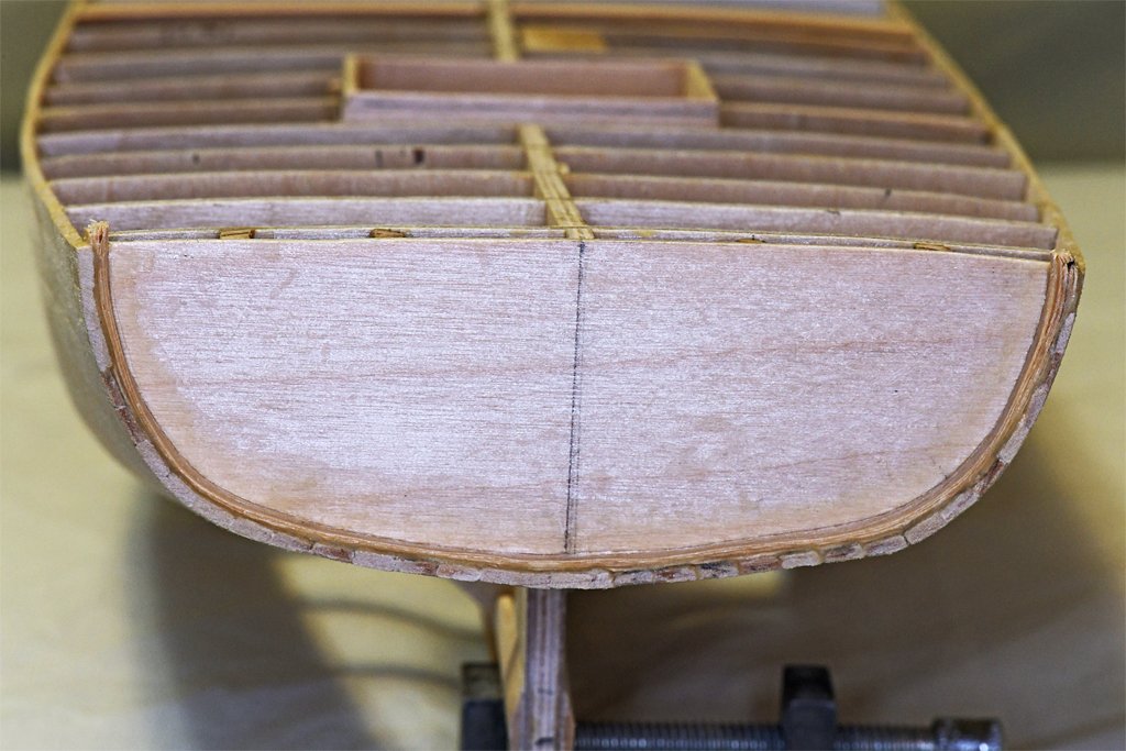
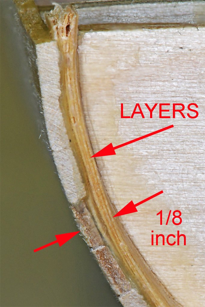
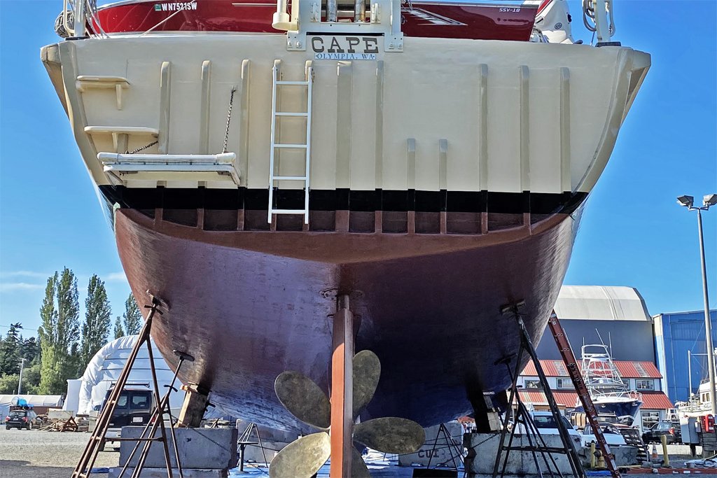
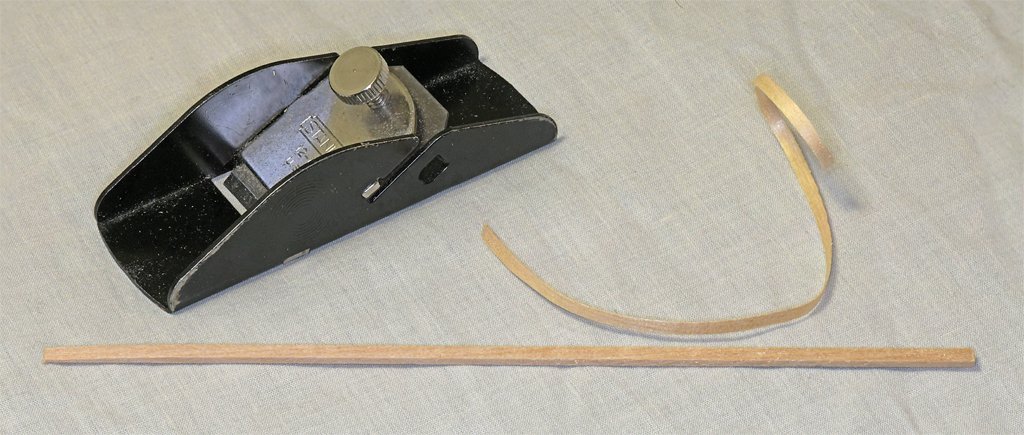
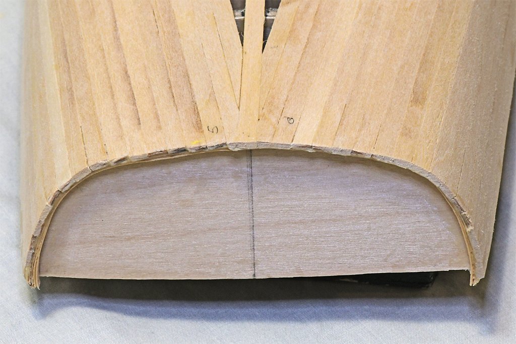
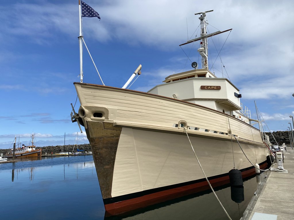
More planking done. Now about 2/3 finished. The planking has come together at the stern so I can start thinking about work on the transom. I have sanded the ends of the planks to about 3/16 inch (4.8 mm) aft of the transom. Around the edge of the transom is a "guard" (what it is called in the blueprints), that should be 1/8 inch (2.3 mm) high off the transom. Here is a photo of the current day Cape stern (thanks to the owner Austin Cox). You can see this guard around the stern. Here is another photo showing the guard on the model. The guard should be 1/8 inch (2.3 mm) wide. The planks are 1/16 inch (1.6 mm) thick, so I needed to add another 1/16 inch to the inside. To do this I glued five successive layers of basswood shavings around the inside of the planking. The shavings are about 0.008 inch (0.2 mm) thick. The glue adds to the thickness to build up to slightly more than the needed thickness. The stern also had the vertical "guard" boards shown in the ship's photo, but in a bit different configuration. It has been modified a few times since it was a Navy vessel. This picture shows the layers of shavings glued around the inside of the planking. After the glue has set a few days I will sand the ends of the planks down to the proper height. Then I will sand the shavings to a better shape and add a plank across the bottom as is shown in the photo of the ship's stern. I suspect a bit of putty will be necessary to finish the job. I made the shavings with my trusty 3 1/2 inch (89 mm) Stanley 12-101 plane. I have had it for decades (it has U. S. A. stamped on the side) so it is probably an antique by now. I selected a 1/8 x 1/8 inch basswood stick and shaved several strips from it. The laminated shavings are the right height for the guard.
- 492 replies
-
- 9
-
-
- minesweeper
- Cape
- (and 1 more)
-
On the ships I served on the gratings were raised above the deck enough to allow water to flow under them. An open cockpit on a small vessel like the schooner would occasionally be awash in heavy seas. so the raised grating puts the helmsman's feet a bit above the sloshing water. However, this keeps the feet only relatively "dry." On the 112 foot minesweeper I was on the open bridge was 15 feet (4 1/2 meters) above the water line. In heavy weather waves occasionally broke over the bridge, We had a raised grating but it didn't keep us dry. Sometimes we had 6 inches (15 cm) of water sloshing across the deck. The grating only allowed the water to drain off our feet some of the time.
-
George, Nice work. Research and figuring out how to make and rig things takes much longer than actually doing the work. Also, I find that even after the research I may still be trying to decide which of several possible ways to do the job I will choose. One of my favorite sayings is "Maybe it is a good thing I am slow because I might be going in the wrong direction."
-
I have been under the impression that the jib boom outhaul was not permanently rigged, but was set up only when the boom was to be hauled out. I recall one example where the end of the outhaul was belayed to a cleat on the bowsprit inside the bulwarks. It could be belayed to a timber head or knight head. Since it was temporarily rigged the belaying point could be anything convenient. It would be rigged only while the jib boom crupper was being put in place.
-
Tony, To answer your original question - no! There are programs that can generate a rough 3D model of something from photos. Multiple images are taken from different positions all around the object. Then with a little prodding the program creates a crude image, often "painting" the original photos onto flat surfaces. I have seen this done to make 3D models of buildings. But I don't know how well this would work for irregular or curved surfaces.
-
I also made a bunch of the modified binder clips, and they are almost worthless. As palmerit noted, if the plank has any twist to it these flimsy clips will not hold down the edge. However, if you bend the plank to fit the hull contours as Dziadeczek said these clamps will hold it in place as the glue sets. It is my opinion that you should never attempt to plank a hull with curves without using a plank bending tool to heat the planks and preform them before gluing. I have posted some example photos and a description of the technique here: https://modelshipworld.com/topic/37060-uss-cape-msi-2-by-dr-pr-148-inshore-minesweeper/?do=findComment&comment=1075263 https://modelshipworld.com/topic/37060-uss-cape-msi-2-by-dr-pr-148-inshore-minesweeper/?do=findComment&comment=1074225 I bend the planks in place on the hull. I clamp the ends of the planks to the bulkheads and then brush on a bit of water. Then I apply the planking iron and the water turns to steam to carry heat into the plank. It is the heat, not the water, that causes the plank to bend. After a single heating step the plank starts to bend. I usually use three wetting/heating passes and the planks will be the shape of the hull. This just takes a couple of minutes to form a plank. For really long planks I heat them in sections, using clamps to hold the remaining plank in place. After bending you can use almost anything to hold them in place while the glue sets. I also have a bunch of the "little metal clamps." I bought some years ago at a model train show and have used them a lot. They are black anodized. Recently I bought a bag of 30 more on Amazon. These are unplated bare metal. The new clamps are wimps compared to the older ones. They have weaker springs and significantly less clamping power. I use these clamps to hold the edges of the neighboring planks together so the edge of one doesn't rise above the other. You can see how this works in one of the photos in the link above. Rubber bands are good for holding planks in place on convex (outwardly curved) parts of the hull. When the hull is concave (curved inward) you will have to insert a spacer between the rubber band and the plank to force the plank down. I use SIG Bond aliphatic resin glue. It starts to set after a few minutes, so you have time to position the plank, and reposition it if necessary. The glue has set after 30-40 minutes, but really doesn't fully harden until over night. While the glue on one plank is setting I cut and shape another. Then the new plank is glued down. I repeat this until I run out of clamps, so the setting time of the glue is unimportant. Quimp Stattery posted a technique of pre-gluing the bulkhead and plank surfaces and then putting the pieces together and using heat to melt the glue to attach the pieces together: https://modelshipworld.com/topic/37071-planking-without-clamps-clean-up-or-drying-time-a-new-way-to-use-titebond-original/?do=findComment&comment=1060839 This could be a way to get a quick setting glue without using cyanoacrylate. I have noticed that this also appears to work with the SIG Bond aliphatic resin glue. I haven't tried it yet, but I may use this technique for planking the deck.
-
Actually, I have had this problem before, especially with the wood in older kits, so I am prepared to deal with it. In this case, since the hull will be painted, varying dimensions in the planks is only a nuisance. But for an Admiralty model intended to showcase the structure of the ship, I would want much greater uniformity in the planks.
- 492 replies
-
- 3
-
-
- minesweeper
- Cape
- (and 1 more)
-
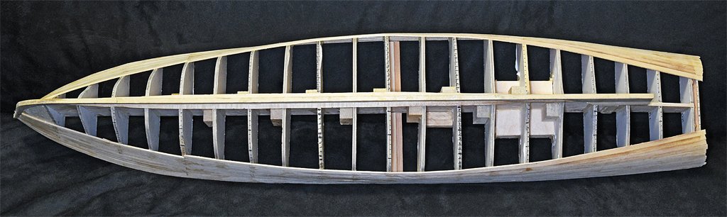
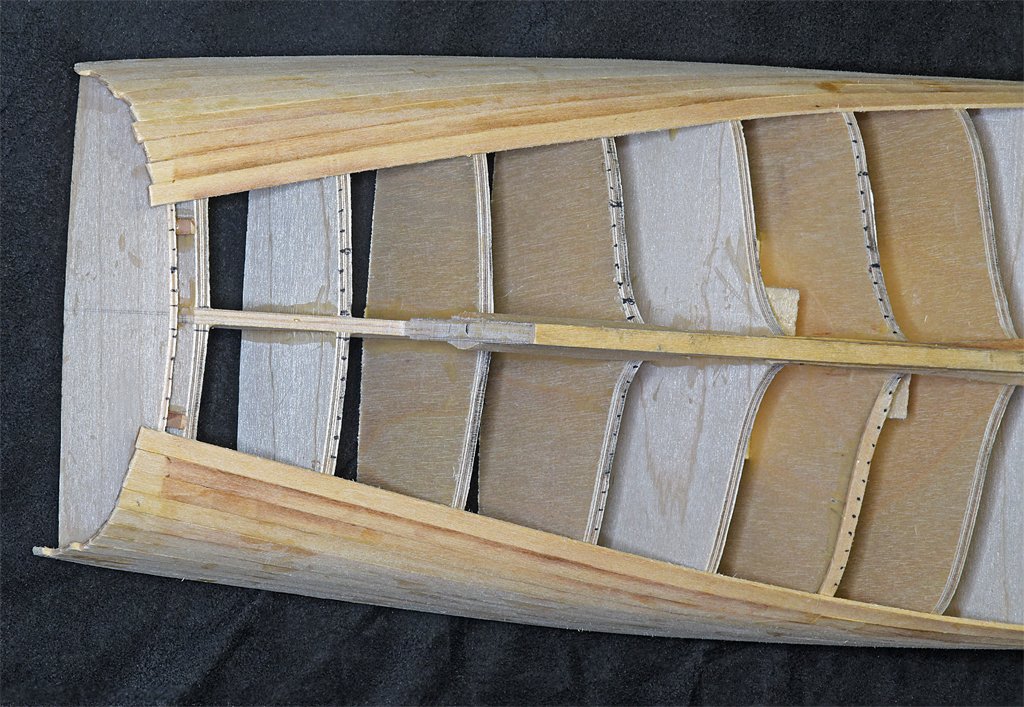
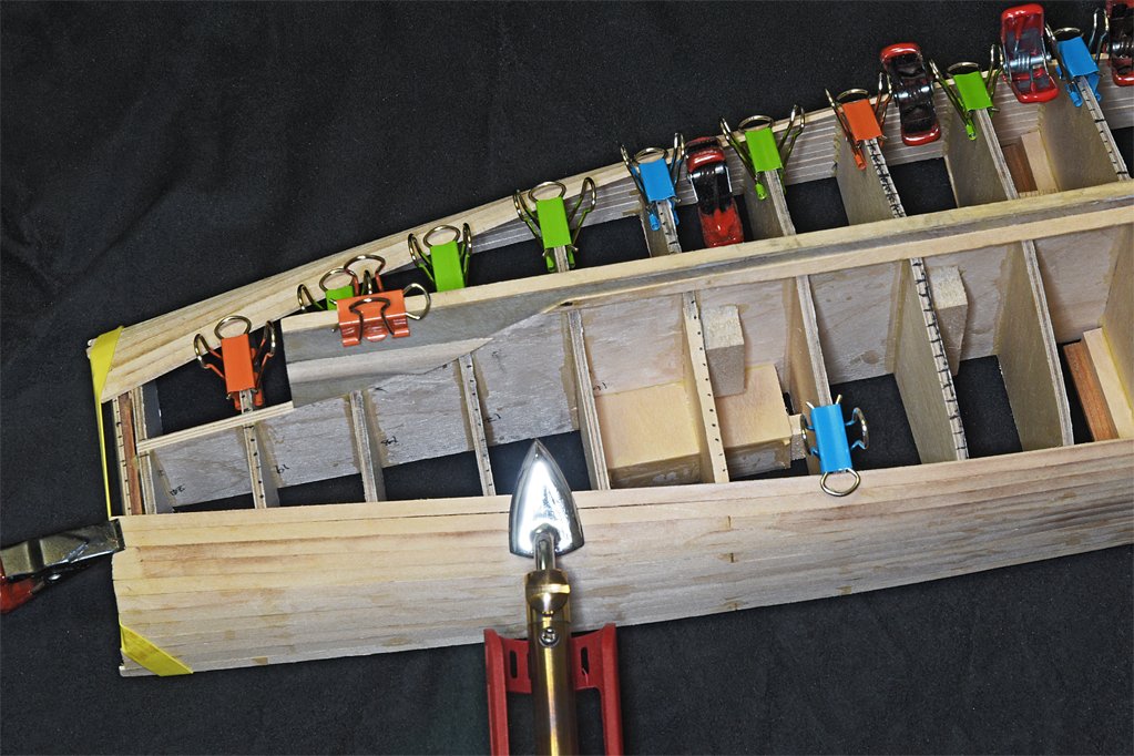
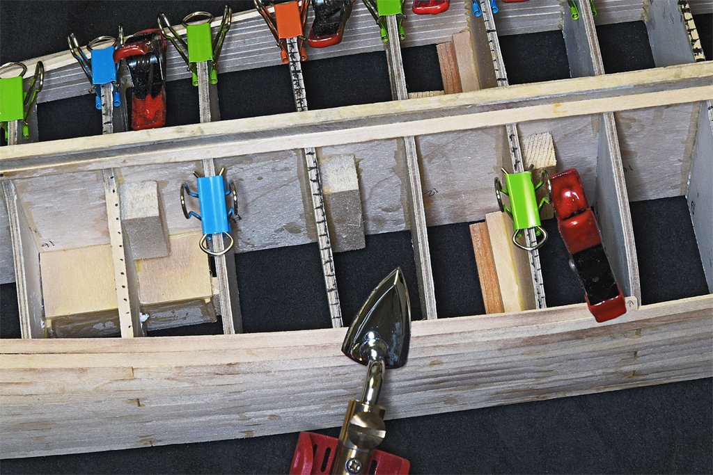
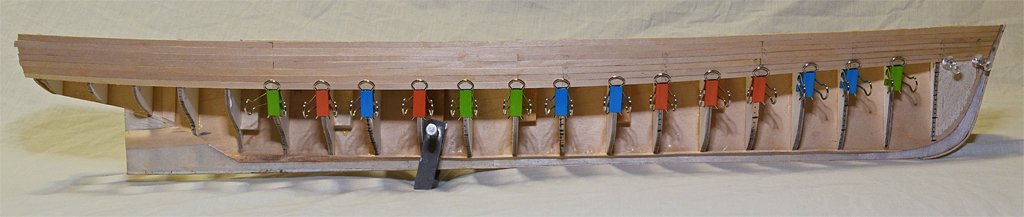
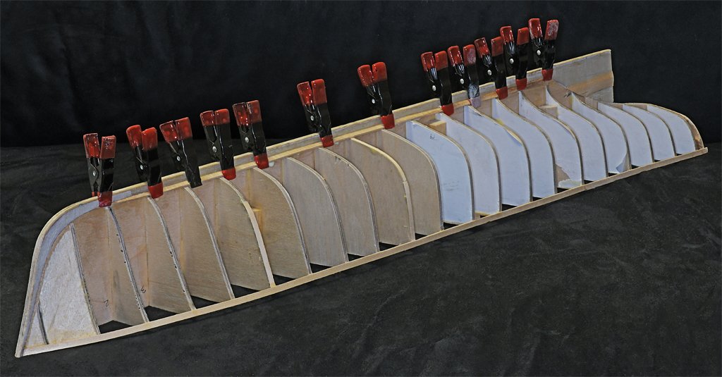
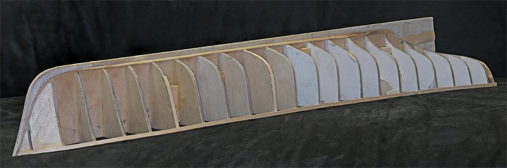
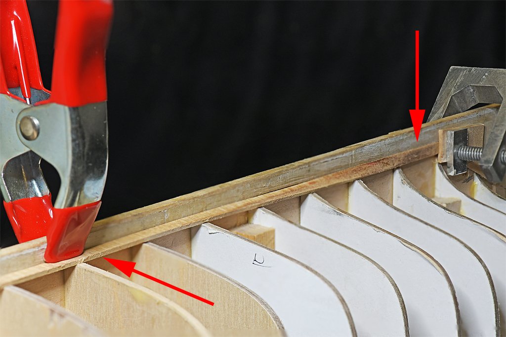
The hull planking is about half done. The top down view gives a pretty good idea of how the hull is shaped. The planks are tapered at the bow, but I have left them straight at the stern. The 1 in 3 pattern creates a butt seam at every fifth bulkhead from the bow. The latest planks are long running from bulkhead 5 to the stern. The short planks from bulkhead 5 to the bow will be added next. The planks are running pretty true to the planking plan. Because the planks I ordered vary quite a bit in width I divided them into two batches, those wider than 0.180 inch (4.5 mm) and those that are narrower. I started with the widest planks in order to keep the planking run about the same on both port and starboard sides. This did cause the planking to creep ahead a bit in some places from the nominal spacing I have marked on the bulkheads. I have used all of the widest planks and now I expect the narrower batch to cause the planking to creep back to the marks. Any differences will be corrected with the last planks outboard of the garboard planks. Here are some more views. The planks are lying nicely with the curve of the bulkheads at the stern. They should come together just about at the top of the aft edge of the skeg where the stern frame fits. I plan to place a center plank along the keel piece that the other planks will join. The bow has been more of a problem. The outward concave flair of the hull requires careful planning and cutting of the planks to maintain even spacing. They must also be fitted into the rabbet behind the keel extension piece. This hasn't gone as smoothly as the planking at the stern. The biggest problem at the bow and elsewhere is that the planks i bought do not have a uniform thickness. Some are significantly thicker than others, and if these are placed side by side the thicker one rise above the neighbors. Adding to this, the ends of many of the planks are only half the nominal thickness. Apparently they were pulled from the thickness sander while still being sanded, causing extra wood to be ground off the ends. I didn't notice this until I had quite a few planks glued in place, and the butt joints where the ends come together have significant discrepancies in thickness. In a couple of cases I have glued a second plank piece on the thinnest parts and then planed, filed and sanded it away until I had a smooth joint. I have had this problem with the wood in some kits, but I expected better quality control from model wood suppliers! After all the planking is finished the stem will be cut down to come to a moderately sharp cutwater. The angle at the bow varies from garboard strake to the sheer strake. It should follow the angle of the planks to create a smooth surface at the rabbet. That is to be seen! However, it doesn't matter if the surface doesn't come out perfectly smooth because the entire leading edge of the bow will be covered by a very thin (0.003 or 0.005 inch, 0.076 or 0.127 mm) brass stem band and chafing plate that extends back some distance beyond the rabbet. I have been using my quilting iron/plank bending/sail making tool to pre-shape the planks where they wrap around the curvature of the hull. In my opinion this is a must do thing when you have planks that have to conform to significant curvature in the hull. I have sometimes gotten by with just gluing the planks and holding them with every clamp and rubber band I can find. The planks will glue down and then eventually conform to the curvature. But some edges will try to rise above the neighboring planks if you don't have enough clamps. If I clamp just the ends of the plank in place and then heat the plank over its length, after a few passes with the plank bender the plank retains the proper twist without the clamps. Then it glues into place easily and requires very little clamping to get it to fit tight to the bulkheads. The little modified paper clips shown here are almost useless. They will not hold down the edge of a plank that is trying to twist back flat. But if you use enough of them after the plank has been bent into shape to conform to the hull curvature they will hold it in place until the glue dries. The larger clamps are holding the edges of the neighboring planks together so neither rises above the other and they form a smooth surface. I wet the planks with water before heating. The water turns to steam, carrying the heat into the plank. Usually the plank takes the shape after a single pass, but I wet and heat the planks three times to be sure they conform tightly to the shape of the bulkheads. I also discovered something else. When I heat a plank any remaining glue (SIG-Bond aliphatic resin) on the bulkheads or neighboring planks melts, and when it cools it sticks to the new plank. Another post on the Forum describes using heat to melt Titebond Original Wood Glue and glue planks in place. Apparently you can do this with SIG-Bond. However, I am careful to wipe away any excess glue before clamping the planks in place. Any excess glue remaining on the bulkheads will cause a new neighboring plank to ride high, and glue on the edges of a plank will cause the seam to be wide between it and a new neighboring plank. CAUTION: I have the plank bender set to the highest heat level and it works nicely at this temperature. But if you look closely at the photo above you will see some scorch marks where the tool has browned the planks. It happens when I hold the iron in one place too long. This is especially noticeable on a couple of the planks at the stern. I don't know how deep you would have to sand the wood to remove this "stain." For this build it is not a problem - the hull will be painted. But if you are building a model where the wood will be visible you probably should use the medium or low heat setting to avoid discoloring the wood.
- 492 replies
-
- 9
-
-
- minesweeper
- Cape
- (and 1 more)
-
The garboard strake may be just another plank, or possibly a little wider than the ordinary planks (but there may be several widths of planks on a hull side). But I have seen cases where the garboard strake was a plank that was wider and a bit thicker than an ordinary plank. And on the MSI model I am building the garboard strake was a very complex shape several times thicker than an ordinary plank and had a variable (non-rectangular) cross section from bow to stern. So the size and shape of the garboard strake depends upon the type of ship, the period, nationality and whim of the ship designer.
-
I shape planks in three ways. 1. #11 blade in a hobby knife. Good for removing larger excess from plank. 2. I have a Stanley 12-101 mini plane. It is 3 1.2 inches (89 mm) long. I use this to shave the edge close to the line. 3. A sanding block with 100 grit sandpaper. I use this to shape the plank to the line, and any other fine shaping that is needed. For beveling the plank edges I use either the plane or the sandpaper block. I bought the Stanley plane decades ago at a local hobby shop. I have sharpened the blade several times, and I retract the blade and keep masking tape over the blade opening when it is not in use. I have used it so much that the black anodizing is worn off the bottom. There are two "types" of planking. If you are going to paint the wood or cover it with copper plates you really don't need to worry about getting everything perfect. A few cracks and asymmetrical (port/starboard) planking won't matter. Varying thickness and widths in the planks also don't matter much (this is common with wood in kits).You can seal the hull and fill in any gaps with putty and then sand it smooth. Then the paint will hide any detail in the planking. But if you are building a model where the wood will be visible and the planking detail emphasized then you need to be very careful and work with precision on each plank. This is a lot harder than you might think, and takes a lot of practice. For this a plank holding jig is useful, especially if it had a provision for angling the plank to the correct angle to get the correct bevel. You will also need planks with carefully controlled width and thickness, and a lot of wood suppliers fail on this point. Hard core modelers make their own planks and control the dimensions carefully. I would caution against purchasing the most expensive tools, especially those designed for specific tasks not common in ship modeling. As several members have said here, they just use hobby knives or scalpels and sandpaper, and they get very good results. A common bit of advice is to never buy a tool until you need it. There are a lot of flashy tools on the market, but many are good only for separating suckers from their money!
-
Does the DecoArt Multi-Purpose Sealer raise the grain on wood?
-
Keith, Those planks are the anchor lining to prevent the anchor from chafing or cutting into the hull planking. The ship also had these linings on each side aft of midships. The port lining was where the ship's boat was put over the side, and the starboard lining was where the large float (or "pig") for the acoustic mine sweep sounder went over the side. There were two more linings on the port and starboard side at the stern where the minesweeping cable floats went over the side. I can see these planks better in some of the higher resolution photos I have of the ship, but I don't know the actual dimensions. I haven't found these in any of the blueprints. They may have been added after the ship was built. These linings were found on all the minesweepers I saw while I was in the service. One problem I faced was trying to figure out how low on the hull the linings went. In the photos they go down to the water line - but then what? Fortunately, Austin Cox (the current owner) sent me a photo of the ship in the slings when it was in the shipyard, and it shows these lining planks go all the way down to the keel! End of problem! The same photo showed how that thick garboard strake faired out at the bow - another thing the blueprints don't show. As you know from your Cangarda build, photos of the real thing are a treasure!
- 492 replies
-
- 5
-
-
- minesweeper
- Cape
- (and 1 more)
-
Kieth, Excellent advice. I found a rambling rover - she's a fearless Jeep girl - and we have rambled to some beautiful places.
- 174 replies
-
- 3
-
-
- Vigilance
- Sailing Trawler
- (and 1 more)
-
Harbor Freight 16" variable speed scroll saw
Dr PR replied to Dr PR's topic in Modeling tools and Workshop Equipment
Thanks to everyone for the comments and suggestions. I don't put the foot directly on the material, but close above it. But if the material lifts against the foot the foot rotates around the single screw holding it to the vertical part. Then it all has to be readjusted. One suggestion was to just raise the foot and not use it. For now that seems to be the best route. But I want the foot in place when I am cutting very narrow pieces because I don't want my fingers too close to the blade! I have experimented with different tooth counts on the blades. Right now I have a limited selection. I tried to make sense out of the Byrnes recommendations for saw blades, but it was for circular blades and didn't give the tooth count per inch the way scroll saw blades are rated. Yes, I could divide the tooth count by the circumference to get teeth per inch/cm - but do you use the point of the tooth or the bottom of the cut for the count - the different radius makes a difference for circular objects. Humphrey, thanks for the warning about car wax and silicones. I will get some Minwax finishing paste wax. -
That's only because I didn't show you a close-up! It is mostly going according to plan, but I had a problem on the port bow. I broke the sheer strake with too much pressure trying to get it to conform to the curvature of the hull. I glued it in place anyway, but it had a bit of an upward bow between bulkheads 1 and 3. That threw off the following planking, and I ended up with a "smile" between a couple of strakes. I cut a filler piece and glued it in place and now the strakes run fair. However, the taper was a bit off and now I am having to cut the port strakes a bit narrow between frames 5 and 1 to make up the difference. It won't show after the hull is sanded and painted. I have also had problems with plank thickness. I am checking plank width carefully and beveling the high side of each plank to fit snugly against the strake above it. But some of the planks are too narrow at the end, as if they were pulled out of a thickness sander too early causing the end to be too thin. I only discovered this after gluing a plank into place and then realizing that the plank that butted against the thin end was quite a bit thicker. Again, I cut a filler piece and glued it in place. Then after sanding the hull is smooth at that joint. Now I check the thickness as well as the width. I am using a 1 in 3 planking scheme. The planking butt joints are at bulkheads 5, 10 and 15, repeating every third strake.
- 492 replies
-
- 4
-
-
- minesweeper
- Cape
- (and 1 more)
-
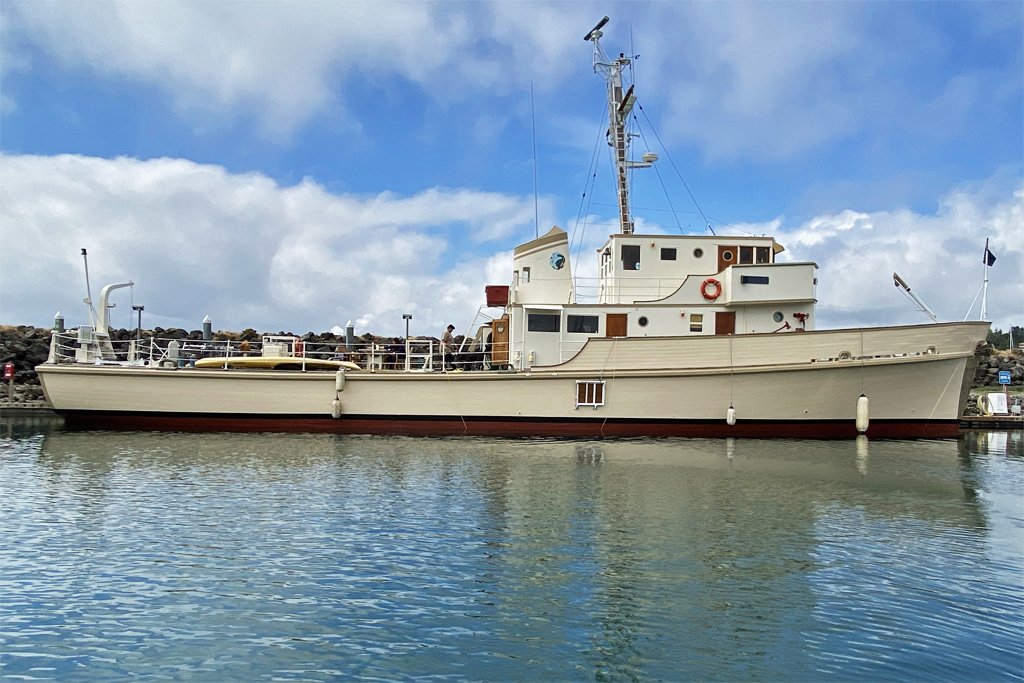
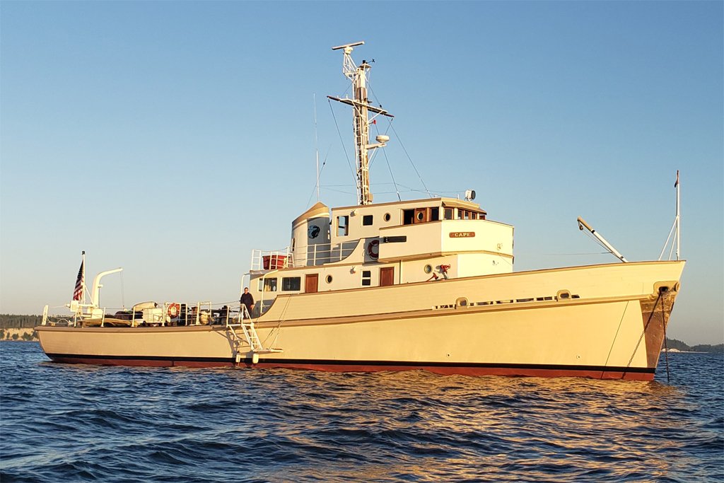
I have been in contact with Mr. Cox and he has provided some photos of the present day Cape. She looks pretty spiffy in her Bristol Beige color scheme. The ship was launched on 5 April 1958 at the Bellingham (Washington) Shipyards Company. The vessel is over 65 years old and still going strong! Austin says the hull doesn't leak (except around the stuffing boxes when running, as is to be expected). After the Navy decommissioned the Cape it was leased in 1970 to Johns Hopkins Applied Physics Lab (APL) and converted for research. I seem to have ties to APL - after leaving the Cape I was in the Talos missile battery on the Oklahoma City. APL designed the Talos missile. The ship underwent a lot of renovations when converted for oceanographic research. The minesweeping gear was removed, and more importantly, a propeller shaft brake was installed. Austin says "I can’t imagine going from forward to reverse using a man powered lever to keep the prop from freewheeling. I wouldn’t be able to go anywhere!" Amen to that! After her oceanographic research career the Cape served as a Naval Reserve training vessel for several years. Then it was sold to an Indian Nation. It fell into disrepair and broke free of the moorings, ending up beached on a sandbar. A fellow got it from the tribe in 1992 and converted it into a yacht. He took it all the way down the Pacific Coast to Long Beach (where it was when I was aboard) in 2002 for a crew reunion. Austin bought the Cape from that owner. He runs an auto and boat repair facility, so she is in good hands now. It is great to see the old girl still looking fit! **** So what about the model? I am plugging along with the planking. 16 of the 52 planks in place. 36 to go!
- 492 replies
-
- 10
-
-
- minesweeper
- Cape
- (and 1 more)
-
Austin, Good to hear from you! The last I heard the Cape was somewhere in the Puget Sound area. Do you have any recent pictures of the vessel? What condition is it in? I suspect the other members of this forum would like to hear more about how the Cape is today and what it is doing. If you want you can send me a personal message through the forum, or you can contact me through this link: https://www.okieboat.com/Contact page.html
- 492 replies
-
- 3
-
-
- minesweeper
- Cape
- (and 1 more)
-
What was the surprise in post #46? Something to do with the mast but you didn't say what. In post #47 are you allowing for the thickness of the cap rail on the bulwarks for determining bulwark height above the deck planking. If the cap rail is also 1/16 inch thick will the height be correct above the 1/16 inch deck planks? From your photos it looks as if part 13 (the subdeck at the stern) is cocked up at a pretty sharp angle.
-
I have been using the ring light for about seven months now. I did get the lithium battery and charger. The rechargeable battery lasts MUCH longer than four AA cells! It charges with a standard cell phone charging cable from a USB jack. I have had no problems and the unit still works perfectly. I have used it for all sorts of photography - even taking it into the field for wildflower pictures.
-
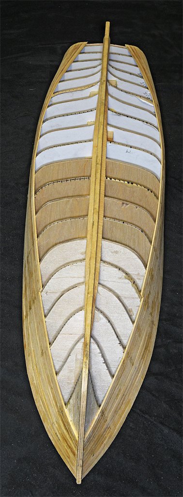
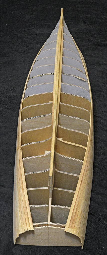
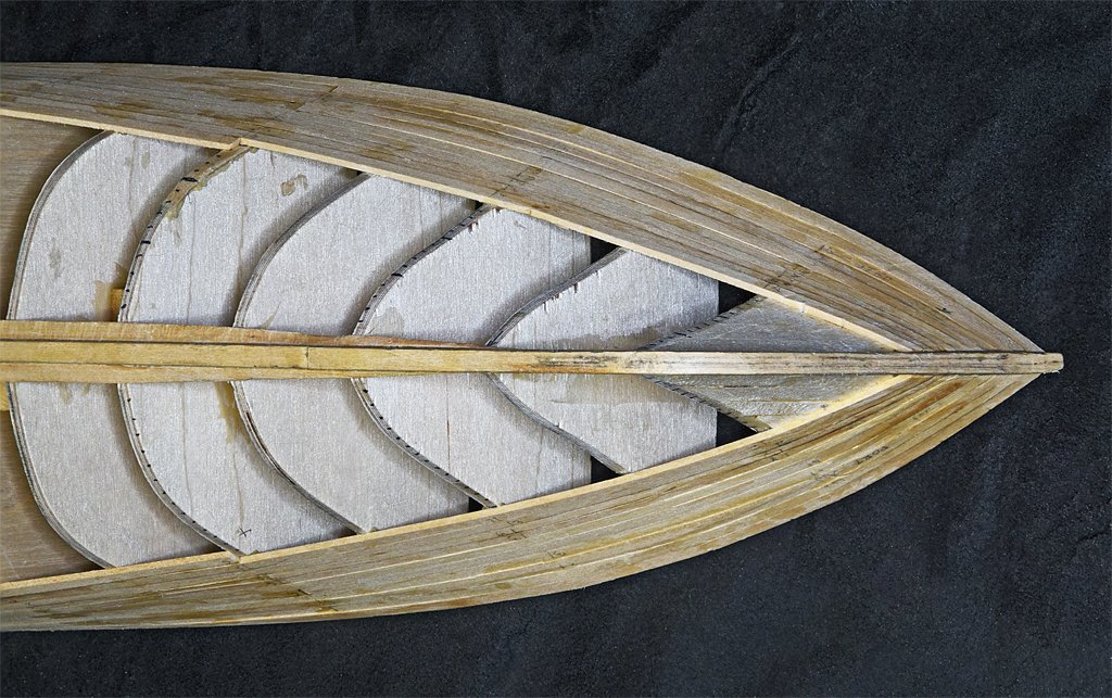
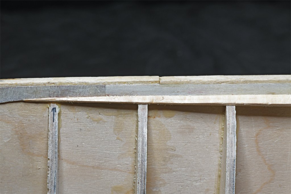
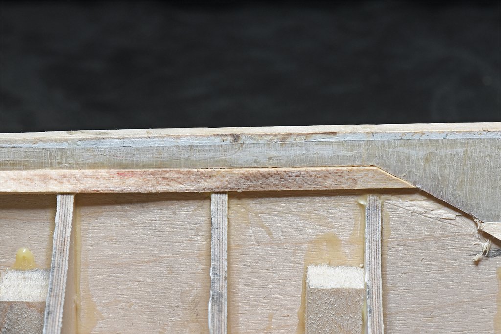
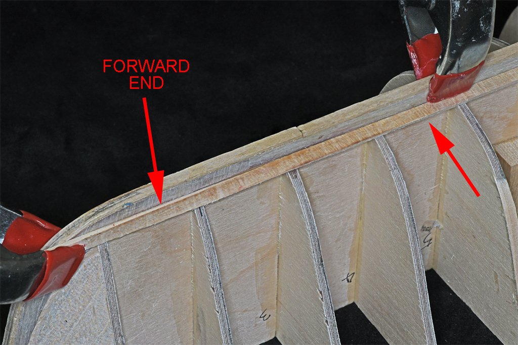
I started work on the garboard strakes today. As described above, I will make the garboard strake in two layers. The first layer is an ordinary plank to set the run of the rest of the planks. The first problem was bending the plank to the curvature of the hull. It must fit vertically at the bow and stern, but twists almost horizontal amidships. I used a single plank for this strake. It was cut it to fit into the rabbet at the stern. I clamped it into the vertical notch on the keel siding, fitting into the rabbet. Then eight bulkheads forward I used another clamp to force it to twist into the almost horizontal position against the keel siding. At the bow I did the same thing. To make the twists in the plank permanent I heated it with my quilting iron/plank bender/sail making tool. First I brushed water onto the twisted plank and let it soak in a couple of minutes. Then I heated it with the plank bender. The water turned to steam and carried the heat into the wood. I repeated this several times, allowing the wood to cool between heating sessions. It is the heat that softens the wood structure, not the water. The water just carries the heat into the wood. Water isn't necessary - I have bent many pieces using heat alone. But I think the water speeds things up a bit. After several heating/cooling sessions the plank retained the twist when the clamps were removed. Then the plank was clamped into place along the full length. Another plank was laid alongside and allowed to ride up and over the garboard strake plank at the bow. I marked a line on the garboard plank along the edge of the second plank. This showed where the straight edge of the second plank would run. Then I trimmed the garboard plank to taper to a point just forward of bulkhead #2. The blueprints do not show a clear diagram where the forward end of the garboard strake ends, but they do show the internal bulkheads in this area, and the garboard strake ends between frames 7 and 9, just a bit forward of my bulkhead #2. After the plank was trimmed I glued it into position using SIG Bond cement. I clamped it securely along the entire length. The glue sets in about 40 minutes, but doesn't fully harden until overnight. But after three or four hours it is OK to remove the clamps. Here is the hull with the starboard side garboard strake. Here are close ups of the forward and aft ends of the strake. I decided to try another method to put the twists in the port garboard plank. I clamped the end vertically. About seven inches from that I clamped the plank horizontally, putting a 90 degree twist in it. Then I alternately wetted the wood and heated it with the plank bender. This was repeated four or five times, allowing the plank to cool between heating. After the plank had cooled the last time the clamps were removed. The plank retained the twist with only a little spring back. The 90 degree twist is more than needed on the hull, so the plank fit into position properly along the port side rabbet. The forward and aft ends must be trimmed to fit and then I will glue it in place over night. The next step will be to mark the plank spacings for the other 24 planks on each side. These planks will be tapered to fit the curvature of the hull.

- 492 replies
-
- 10
-
-
- minesweeper
- Cape
- (and 1 more)
-
Are those electric plank benders worth it?
Dr PR replied to Spaceman Spiff's topic in Modeling tools and Workshop Equipment
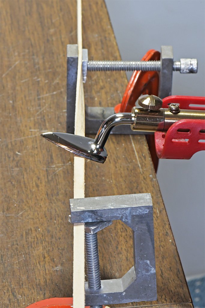
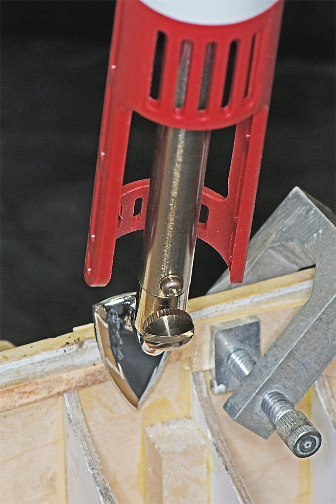
I saw this little Mini Iron II (Clover No. 9100) "quilting iron" recommended as a plank bender in another thread. It is sold as a small iron for use with quilt making. However, it is basically a small 40 Watt soldering iron with a special tip. I have used it many times now and can recommend it as an inexpensive and versatile model making tool. The picture on the left shows the tool being used to bend a plank that is already clamped in place on a hull. The photo on the right shows it being used to heat the bend into a plank that has been twisted between two clamps. In both cases brushed some water onto the surface of the plank and then heated it with the iron that was set to the highest heat setting (it has low, medium and high settings). It is the heat that sets the bend into the fibers in the wood. All the water is for it to conduct the heat into the wood. But this is not the only use for this tool. It is also useful for making sails. I used it to iron the sail material smooth - it is not nearly as bulky as a large fabric iron. I also used it to set the glue when adding tablings, linings and bolt ropes to silkspan sails. The low heat setting is safe to use with silkspan. And who knows? Maybe some day you (or someone you know) will want to make a quilt.

-
Dowmer and John, thanks! A nice thing about the diluted white glue (Elmer's Glue All) is it dries clear and is invisible. So it is perfect for gluing down the ends of the points. Even better, it is totally transparent when the sail is back lighted - although the glue is there it is not visible but the shadow of the points on the back side is. The combination of silkspan and white glue is very good for sails. In an earlier post I said if I couldn't erase all of an errant pencil mark I could just paint over it with the same paint I used to color the sails and the mark wouldn't be visible. While this is true, the additional paint shows up as a dark splotch when the sail is back lighted! Not perfect! But most models are viewed with light from the viewer's direction so it really isn't noticeable. But is is better to not have errant pencil marks! Another thing I have noticed is that some modelers use multiple layers of silkspan on each sail. I am not sure why they do this. One reason for using silkspan is that it is very thin, close to scale thickness for sail material. Perhaps for larger scales (1:35 or 1:25) a thicker material would be better, but there are several thicknesses of silkspan, I used the thinnest for this 1:48 scale model, and it is about 0.001 inch (0.0254 mm) thick, or about 0.05 inch (1.27 mm) at 1:1 scale. Light weight modern cotton sail cloths are 0.012 to 0.025 inch (0.3 to 0.65 mm) thick (1:1 scale). So the thinnest silkspan is about a medium weight scale sail cloth at 1:48.
