Dr PR
-
Posts
2,471 -
Joined
-
Last visited
Content Type
Profiles
Forums
Gallery
Events
Everything posted by Dr PR
-
 Caution: This is a nauseating tale! The Cape was a very small ship - too small to be out on the ocean, in my opinion. Shortly after I reported aboard I discovered I was prone to sea sickness - motion induced nausea. This is caused by conflicting reports to the brain from your eyes and the inner ear balance organ. If one reports you are moving and the other says you aren't - as can happen when you are in an enclosed box bobbing on the sea - you become nauseous. On calm days there was no problem and I enjoyed being at sea. But if the sea was rough and the weather nasty I was nauseous all the time. On one occasion we left Long Beach in a line of minesweepers headed out for an exercise in the Santa Barbara channel off the coast of California. As the day progressed the wind picked up and the ocean became very choppy. My watch station was on the bridge, and it pitched and rolled pretty actively. I was nauseous the whole time and hung out by the rail on the downwind side. If I had to puke I would wait until the ship rolled that direction. Once while I was contemplating such a move my supply petty officer came up and asked how I was doing. He was peeling an orange and the smell of it immediately cured my nausea! I asked if we had any more, and he pulled another one from his pocket. I told him that from then on when we got underway I wanted an extra crate of oranges on board. Hey, I was Supply Officer and if I wanted oranges we would get oranges! Unfortunately oranges only cured mild nausea. Later than evening we ran into a full blown gale, with waves high enough to come crashing down on the bridge. It was an open bridge, but we did have a frame with windows across the front and a canvas awning above. Still, when green water washed onto the bridge we had ankle to knee deep water sloshing across the deck. My shoes and pants were soaked, I was really nauseous, and by the time my watch was over I was exhausted from hanging on. It was like a very wet hours long roller coaster ride. After I was relieved I went below and crashed in my bunk. I managed to catch short stretches of sleep, but was suddenly awake, only to realize the ship was dead quiet - the engines had stopped. I slipped on my shoes and stumbled toward the engine room. As I passed through the mess deck the starboard weather deck door was open, and I saw a large gray wooden wall pass very close down our side. When the engines stopped we lost all power and went totally dark. The ship following us in the storm lost sight of us and almost ran us down from astern. When I reached the engine room I found that the duty watch had forgotten to fill the day tank at the beginning of the watch and we ran out of gas. Both the propulsion engines and the generators ran from the same day tank, so everything shut down in short order. The engine crew used a manual pump to transfer fuel from the main fuel tanks to the day tank, and in about 15 minutes we were underway again. When I got back to my bunk I was exhausted and nauseous. Through the night I would occasionally flop out of the bunk onto the deck and crawl to the head. There I embraced the porcelain throne and called for Ralph O'Rourke. I was too weak to walk, and eventually was pukeing up liver bile. It is bright yellow and tastes horrible. I was unable to stand my next watch. But by morning we reached the shelter of the lee side of Santa Rosa Island and dropped the hook. There it was relatively calm and I got some sleep. When I woke I was able to eat something and hold it down. So why am I telling you this? Two things came out of that experience. First, I became conditioned like Pavlov's dogs. Pavlov rang a bell before feeding his dogs. After a while he discovered that if he rang the bell, even when there was no food in sight, the dogs began to salivate. This is known as a conditioned reflex. For me, when the last line went over the side and the ship sounded three toots on the whistle to signal "underway" I immediately became nauseous - even in calm waters in port. Three toots and I wanted to puke. It took me years to get over this. I don't know, maybe I might still have this conditioned reflex! The second result was that a note that I became chronically seasick went into my medical record. When I later reported to the Oklahoma City the Commanding Officer asked me about it. I told him I did become nauseous but I could still stand watches and do my duties. He was especially interested because I was replacing an Ensign K. who became incapacitated because of seasickness. It was so bad he wanted a medical discharge from the Navy. But instead of a discharge he was transferred to the Yokosuka Naval Hospital where every day they strapped him in a chair and rotated and tumbled him until he puked. They wanted to be sure he wasn't faking it. So Ensign K. was tortured for several weeks until they finally sent him back to CIVLAND. And just to be sure about me, when we were next at sea the CO had the Officer of the Deck I was assigned to (as Junior Officer of the Deck) smoke particularly nasty cigars and blow the smoke in my direction. All just to see if he could make me puke. I didn't, and the CO was satisfied. But I did toss my cookies once in the 27 months I was on the cruiser. It wasn't in the typhoons when we alternately walked on the decks and bulkheads and hung on for dear life - I was too busy to become nauseated. It was one night on relatively calm seas with a long steady roll, when I was on watch in the Combat Information Center deep in the bowels of the ship. I didn't even realize I was nauseous until I was returning to my bunk. The ship rode up on a swell as I was climbing a ladder and suddenly dropped just as I reached the top step, leaving me hanging in the air. I came down without my supper. I tell this tale to describe for you a little mentioned part of the experience of life on a small ship. And now you know why I am not interested in going to sea again!
- 492 replies
-
- 8
-

-

-
- minesweeper
- Cape
- (and 1 more)
-
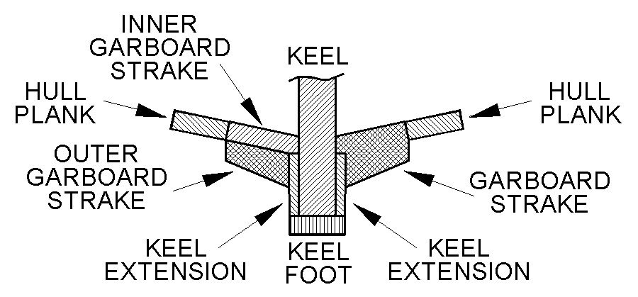
Brian, Are you suggesting placing 15 separate blocks "at the base between each of your bulkheads?" I can't see how that would make it any easier. Or are you thinking of fitting one long strip the full length from bulkhead 1 to bulkhead 15 and then shaping it in place? I thought about this. The thicker piece would be difficult to twist to conform to the changing angles. It would require shaping the piece to fit the angles between the keel and bulkheads at the rabbet at each bulkhead. No two angles are exactly the same, but I think I probably could do this. This shaping would be on the interior so it wouldn't have to be "pretty." I was thinking of using a 1/4 x 1/4 inch (6.35 x 6.35 mm) basswood strip for this. But I do not think it would be possible to form the visible two sides by sanding with the strip in place. It would have to fit against the keel, and I cannot sand right up to this joint without damaging the surface of the keel extension piece. The garboard piece must also be the same thickness at the outboard edge as the 1/16 inch (0.039 mm) planks and parallel to the plank edge. That outboard edge actually has two surfaces at slightly different angles and this "corner" would be extremely difficult to shape in place. See the single piece garboard strake in the right hand side of the drawing. Note: I can simplify the shape to just four sides by trimming the Keel Extension piece but it would have to be done very carefully to avoid having a messy joint showing. The virtue of first using a 1/16 inch thick basswood strip for the inner garboard strake (left side of the drawing) is that it automatically has the right thickness at the left and right edges, and it will fit easily into the rabbet with a bit of sanding. It will twist to conform to the bulkhead shapes from almost horizontal midships to vertical at the skeg. I have already tried this and a plank bends easily with just finger pressure. Then I would trim another plank (outer garboard strake) to the desired thicknesses and angles and glue it onto the first plank. This second piece would be thin and would also twist easily to conform to the shape. It is basically the same thing you would do for a double planked hull, but only one strake. Whatever I try to shape these outer pieces I suspect I will have to repeat it several times to get it right.
- 492 replies
-
- 6
-
-
- minesweeper
- Cape
- (and 1 more)
-
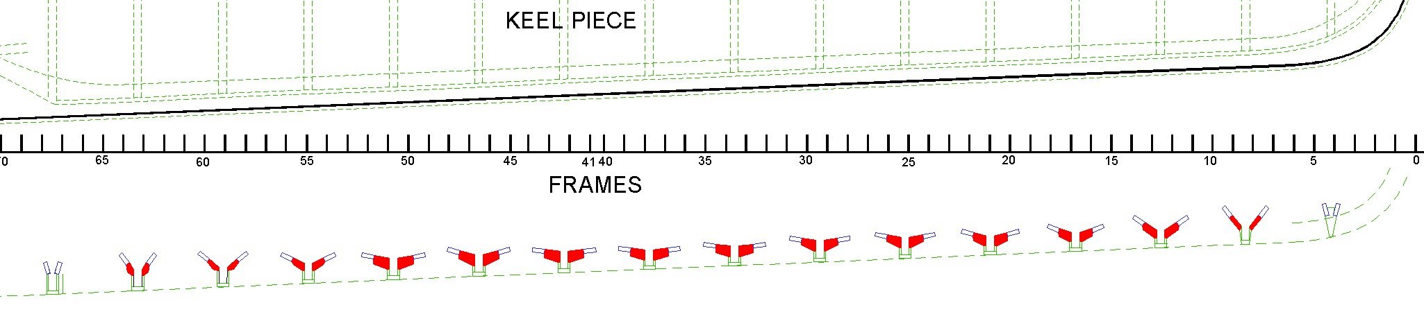
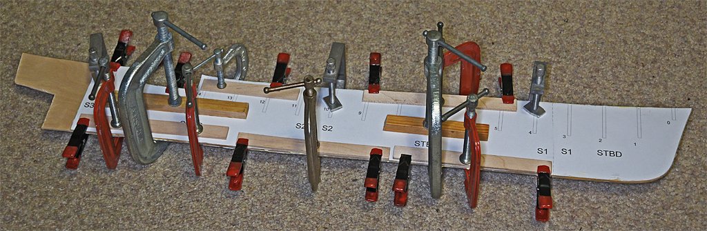
I mentioned earlier that the center/keel piece is only 1/8 inch (3.175 mm) thick and it should be 3/16 inch (4.76 mm) thick - at least at the keel. To widen it to the desired thickness I cut some keel extension pieces out of 1/32 inch (0.79 mm) three ply plywood. The thin plywood cut easily with kitchen scissors, and was finish shaped with sandpaper and files. These pieces were glued onto both sides of the keel with SIG Bond adhesive and clamped tight with all the clamps I could find. After all the keel extension pieces were in place I added a 3/16 x 1/16 (4.6 x 1.6 mm) basswood strip keel foot to the bottom of the keel. With these pieces added the frame is ready to hold the bulkheads in place so I can start planning the planking. This leads to the next problem - the garboard strake puzzle. It will fit from where the bow starts to curve upward back to the beginning of the skeg ahead of the propeller and rudder. But in the ship's blueprints the strake is anything but just another plank. In this drawing (above) the red objects are cross sections of the garboard strake at each bulkhead position on the model. For reference the frame scale for the ship is shown. The green parts are the keel extensions and the keel foot. The blue rectangles are the first ordinary 3/16 x 1/16 (4.6 x 1.6 mm) basswood hull planks. The extra thickness of the garboard strake is more like the thick wales on older wooden sailing ships. The irregular four-sided shape varies from frame to frame. Tricky! Right now I think I may just cut a variable width 1/16 inch (1.6 mm) thick basswood strip to fit into the rabbet to serve as the inner part of the garboard strake. Then the rest of the planking can proceed. Meanwhile I will fashion a second piece with the odd four-sided cross-sections to be glued on top of the inner garboard strake plank.

- 492 replies
-
- 8
-
-
- minesweeper
- Cape
- (and 1 more)
-
Pak75, The discussion about rings or ring bolts on the sides and tops of gun carriages is a lengthy one. Different navies did things differently, so there are a lot of answers. Often gun carriages had two rings on each side, or in the case of the French at some period, rings on the top rear part of the carriage. I suspect which of the two rings were used depended upon the firing angle. Guns weren't always fired perpendicular to the ship's side or the centerline. They could be angled to fire a bit forward or aft of abeam. In some cases the tackle appears to have been unhooked from one ring and hooked to the other to get a better angle or to keep the two blocks from coming together (two blocked) before the desired angle was achieved. I have seen drawings depicting both arrangements. My guess is that the gun crews did whatever was expedient at the time regardless of what the books showed. Another point to remember - often the inhaul tackles (attached to the rear of the carriage and used to haul the gun inboard) are shown rigged. This might be the case while the guns are being fired, but I doubt it. The recoiling carriage would run over the tackle. This tackle would be needed only if the gun misfired, or if it wasn't fired after being run out. And it would be used to haul in the guns if they were stowed run out (in battery) and plugged. If your model has the guns in the stowed position the inhaul wouldn't be rigged. It would be a tripping hazard. The tackle would be stowed in a dry place out of the way. The gun tackle was attached to the carriage and pulled tight before the gun was fired. The rope was faked down so that it would run free without tangling. When the gun recoiled it pulled the tackle rope through the blocks, and the friction acted as a brake to slow the gun before it reached the end of the breech rope. And Henry was just wondering if you have a true name, or if your mother actually named you Pak75?
-
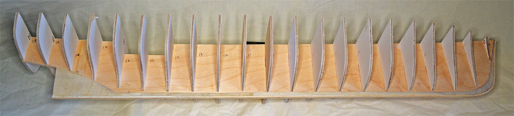
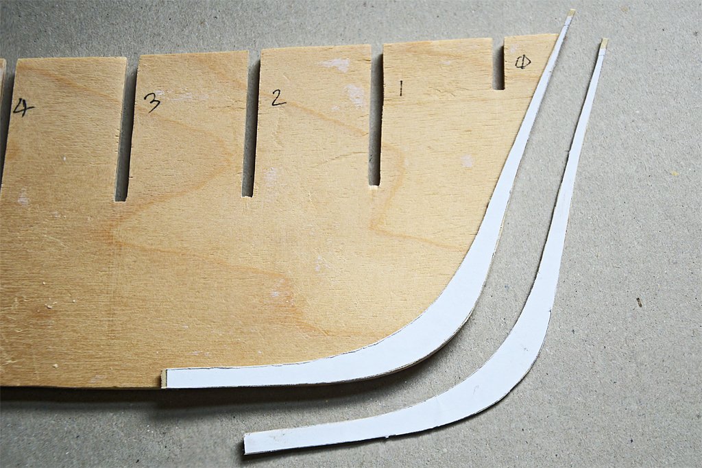
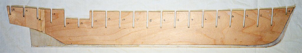
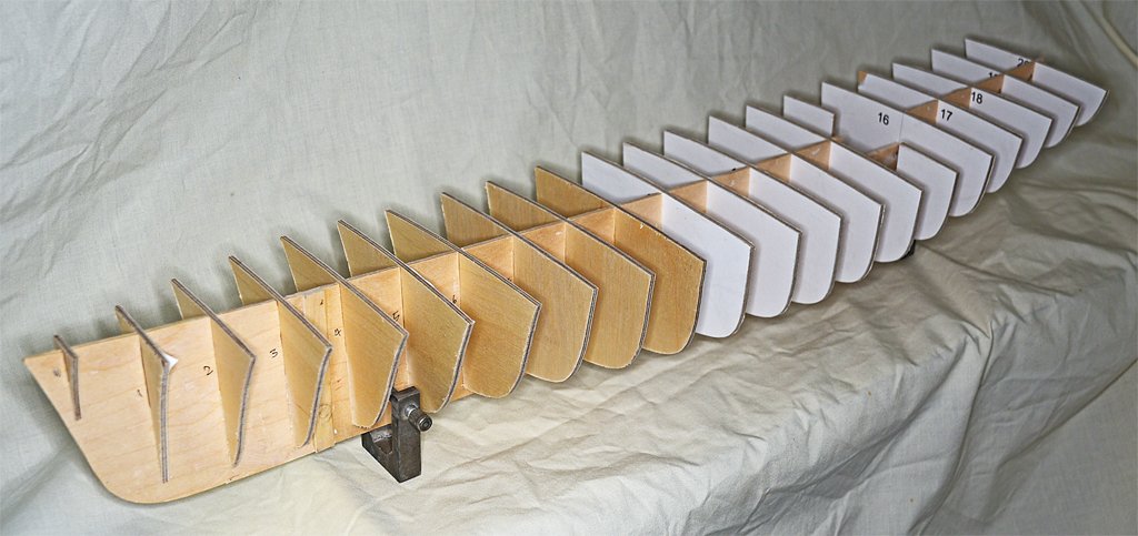
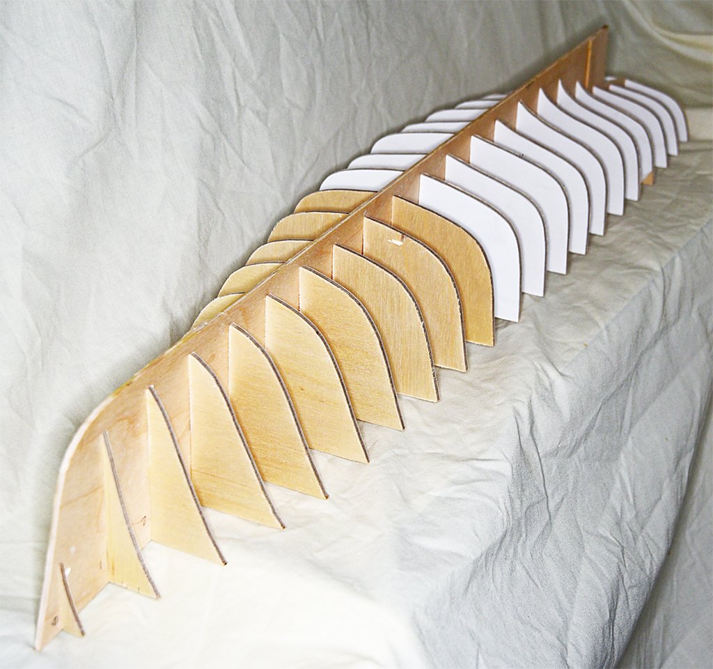
I have finished the initial shaping of the bulkheads and fitted them to the center frame/keel piece. None of the pieces are glued in place yet. There is still some adjustments to make - a couple of the bulkheads are sitting a bit too high so I will have to use a file to trim everything to fit. There is quite a gap between the bottom of the bulkheads and the bottom of the keel piece. This is because the garboard strake will be fitted in this area, and it is a very complex shape (to be described in another post) instead of just a simple plank. The 1:48 scale keel piece is 1/8 inch (3.175 mm) wide, which is 6 inches (152 mm) at 1:1 scale. But the actual keel was 9 inches (229 mm) wide, or 3/16 inch (4.76 mm) at 1:48. I will cut two additional pieces (port and starboard) from 1/32 inch (0.79 mm) three ply plywood (SIG Manufacturing) to fit on each side of the keel and bring it to the correct width. The top edges of these pieces will be the rabbet the garboard strake rests against. The final keel piece will be a keel foot 3/16 x 1/16 inch (4.76 x 1.59 mm) basswood strip to be glued to the bottom of the plywood center frame/keel. After all of this is done the keel assembly at the bow will have to be shaped to a "V" cross section. This will actually be a bit complex because the ship had metal plating around the bow and a cast bow chock at the main deck level. But that is some distance ahead. At the stern will be an aluminum or Plexiglass extension of the keel that forms the frame for the propeller shaft and rudder, quite similar to what Keith Aug made for his Cangarda model. But it won't be as fancy as his work because I don't have the machine shop tools. So I will carve it by hand with drills and files. I won't be using brass because the 1/4 inch (6.35 mm) thick piece I would need costs about US$100.00 from McMaster-Carr! Aluminum is cheaper (and easier to carve) and I probably have a suitable scrap of aluminum or a piece of Plexiglass that will work in my scrap box. Note: I removed the glued on paper templates from the center piece with a wide flat end blade. Most of it peeled off fairly cleanly. But some resisted scraping so I sanded that off. Most of the remaining Elmer's Glue Stick glue scraped off cleanly and the rest came off with sanding.

- 492 replies
-
- 9
-
-
- minesweeper
- Cape
- (and 1 more)
-
USS Constitution by mtbediz - 1:76
Dr PR replied to mtbediz's topic in - Build logs for subjects built 1751 - 1800
Mustafa, Isn't it interesting how we get started on seemingly endless processes, like making all those angled spar deck beams, tying endless knots for ratlines or rigging all the lines to cannons, and when it is finished we are so happy when it is finally done! It's like beating your head against the wall, because it is so nice when it stops! -
A disc sander is really useful for creating chamfered edges like the tops of bitts and knight heads, catheads and such. After the angle is set you can make the same cuts on multiple pieces. And it is useful for cutting the same angles on many pieces. You can do this my hand with files or sanding blocks but getting the exact same angles is difficult. A belt sander is very useful for shaping pieces, trimming to a mark, etc. I recently bought a cheap belt and disc sander at Harbor Freight. Here is a review. https://modelshipworld.com/topic/37369-harbor-freight-combination-belt-and-5-disc-sander/?do=findComment&comment=1070074
-
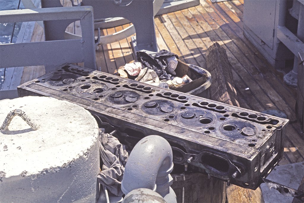
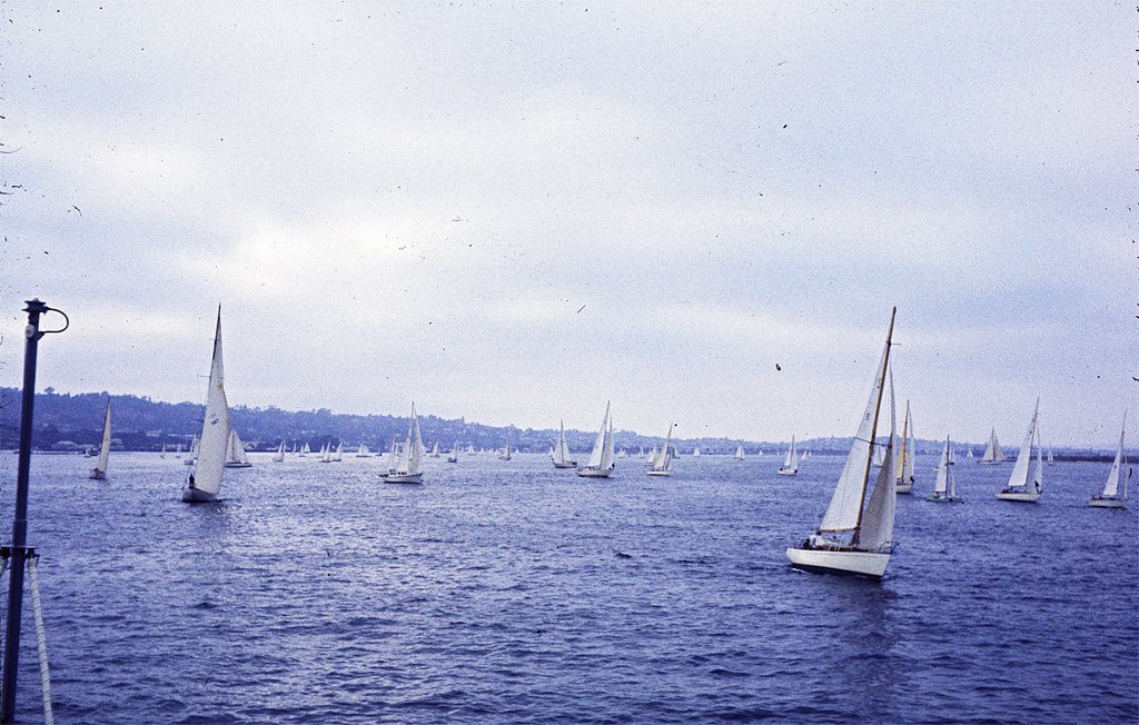
Some of you have expressed interest in my "sea tales" while aboard the Cape. Remember - you asked for it! By now you should have some idea what it was like to serve in McHale's Navy. But I may have given the wrong impression. I said the ship was "bolted to the pier." But we did get underway about once each month. Sometimes it was just to go fishing, and other times were on minesweeping exercises. But on one occasion we went to San Diego to visit the shipyards for planned maintenance. The Navy had a Planned Maintenance System (PMS) that scheduled maintenance based upon statistical evaluations of system failures. The idea was to make repairs before they were actually needed. So one day we headed out from Long Beach to go to the shipyards in San Diego for planned maintenance. Why San Diego? I have no idea. The largest shipyard on the west coast was in Long Beach, a few hundred yards from where we were berthed. But we set out for the San Diego shipyard, approximately 120 nautical miles by sea. We plodded along at about 8 knots, for about 15 hours. We left Long Beach about 4 PM (1600 Navy time), making most of the voyage at night. The plan was to arrive at the channel entrance before 8 AM (0800) and proceed in to the shipyard in daylight. The entrance to the channel is marked by a series of buoys. You "pick up" the outer marker first, and take it down the port side. Then you follow the buoys into the channel, taking each down the port side. Out bound vessels do the same - the buoy on the port side - so you pass ships going the opposite direction on opposite sides of the channel. It sounds simple, but this time we were in a dense "pea soup" fog bank, with no visibility beyond the jack staff on the bow. Finding the first buoy was a challenge. It had a light, but that wasn't visible for very far in the fog. It had a fog horn so we could hear it when we got within a few miles, but it gave only the general direction. The buoy had a radar corner reflector on top, and that showed up on our surface search radar. If the sea is calm a reflector is easy to track. But if there are many swells each wave top appears as a "blip" on the radar, and the reflector is lost in the clutter. But if you pay close attention you can see the blip that remains fairly constant. Marking it on the radar PPI (Plan Position Indicator) screen with grease pencil lets you follow its relative course until you close on it. So we proceeded slowly into the channel. As we came close inshore the fog bank lifted and we had clear visibility into the channel between Point Loma and North Island. But the channel was anything but clear! There were hundreds of sailboats all across the channel, headed our way! According to the rules of the road, sailboats have the right-of-way over all motorized vessels, except ferries. They were swarming all around us, with some passing so close beneath our bow that we could only see the tops of the masts! As I have explained before, we had almost no maneuverability at slow channel speeds. But it would have done no good to try to avoid one of these boats, because if we turned we would just run into another! What was going on? Well it happens that morning Sharon Adams was coming home to San Diego, having sailed from Yokohama, Japan. She was the first woman to sail solo across the Pacific, and just about every boat in San Diego was headed out to greet her! It was July 25, 1969. We didn't have a clue to what was happening, but we did make it through the swarm of small boats. It was like walking through a swarm of gnats. No real problem, but annoying. The next challenge was the ferries connecting the city of San Diego to North Island across the bay. Two ferries crossed the harbor simultaneously, starting the same time from each side and crossing at the center of the channel. They had the right-of-way over us. But because of our lame engineering plant, there was no chance of us stopping if one crossed in front of us. And it would have looked very bad if a US Navy ship ran down a ferry! As we approached the crossing we throttled back and waited until the ferries started out from their landings. When they neared the center of the channel we "gunned it" and raced at the best speed we could make toward the point where they passed each other. They were approaching their berths when we crossed their route, and we proceeded to the shipyard without further incident. We spent several days in the shipyard while the yard people overhauled our engines and did other maintenance. The crew had liberty except for the duty crew on board. For several days I explored San Diego, taking in the sights, including Balboa Park. The zoo there is one of the best in the world. The San Diego Museum of Art is amazing! And since San Diego was one of the first hubs of aviation, the Aeronautical Museum is one of the best, with an original Ryan M-2 like the one Lindberg flew across the Atlantic (the Spirit of Saint Louis was built in San Diego). Then with our engines overhauled we started back to Long Beach. The trip out of the harbor was uneventful until we rounded Point Loma and headed north. We were chugging along when suddenly there arose a clatter from the engine room that was audible topside, even on the bridge. Our senior engineman happened to be topside taking in the air when he heard the noise. He pulled the emergency shutoff levers near the funnel that cut off air to the engines. While we drifted close to shore, with the currents carrying us south into the shipping channel, the engine crew started trying to find the problem. It turned out to be one of the four GMC 6-71 main propulsion engines. The people performing the maintenance in the shipyards had failed to tighten the locking nuts on the rocker arms on one engine. The vibration from running caused the adjustments to change, and eventually the intake and exhaust valves moved deep enough in the cylinders to hit the tops of the pistons. When that happened the heads of some of the valves broke off, and the loose valve heads started carving chunks out of our very expensive non-magnetic cylinder heads and pistons. In two of the cylinders they punched through the tops of the pistons, allowing the burning fuel-air mixture to blow into the crank case and burn the lubricating oil. So much for planned maintenance! We proceeded on under three engines and eventually got back to home port in Long Beach. It was anything but an uneventful and routine voyage! We repaired the engine ourselves in Long Beach with the help of a few cans of coffee and a canned ham or two. Oh - I finished gluing the center frame/keel pieces together and trimmed the piece so it is ready for fitting the bulkheads. I also cut out the O1 and O2 decks so I think all of the pieces are ready to start assembly. But first I think I will finish the sails for the Albatros and try to complete the rigging.

- 492 replies
-
- 9
-
-
- minesweeper
- Cape
- (and 1 more)
-
I looked at several places on line and found the typical posts by people who are clueless. The recommendations are to use acetone, rubbing alcohol, some brand detergent (cleans everything, cures cancer and removes unwanted hair!), cooking oil, mineral spirits, denatured ethanol and soapy water. Since it is for use by children I suspect it will wash off with water. It seems to wash off my hands easily with water. The Elmer's web site isn't much better that the other sites, but it does say to try scraping it off after it dries. The problem with trying to wash it off is that I don't want to delaminate the plywood or to have the glue soak in deeper. These surfaces will be painted (1960s ocean gray) so I suspect I will end up sanding the surfaces to remove glue. Maybe I will just cut two new pieces.
- 492 replies
-
- 3
-
-
- minesweeper
- Cape
- (and 1 more)
-
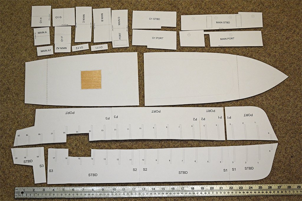
I cut the sub deck and deckhouse parts from two sheets of SIG three ply 1/16 inch (1.6 mm) plywood. The sheets were 24 x 12 inches (610 x 305 mm), but the hull is 27 inches (686 mm) long, so I had to cut the sub deck in two pieces. I cut the hull center frame/keel in four pieces, two each starboard and port. I want the center frame to be 1/8 inch (3.2 mm) thick, and I couldn't find a sheet of 1/8 inch plywood that long. So I decided to cut it from 1/6 inch plywood and glue the pieces together with SIG Bond cement. The joins on the port and starboard sides are at two different places so there is 1/16 inch ply on one side at each join. After it is all glued together I will glue 1/2 inch (12.7 mm) strips along the joins to make 1/8 inch and 6 ply at each join. In the photo the port bow piece is already glued in place, but the starboard stern piece has not been attached - it will be the last. The pieces are all rough cut except along the keel and where the parts come together. I will finish shaping the parts to the lines after the glue has set. Then I will open the slots for the bulkheads. That will take a lot of individual fitting because the glued sheets will not be quite as thin as the 1/8 inch plywood. As the glue is setting up I checked to ensure than the keel piece is straight. It appears to be, but if there is any curvature it will be slight and easily corrected when the planking is started. Also, I will need to remove the glued-on paper from the main deck deckhouse sides. I should have printed the paper templates backwards so they would be on the insides of the parts, but I didn't think of it until after I had already glued them onto the plywood. All the other parts can be used with the paper on the inside where it won't be visible. Anyone have any suggestions for removing Elmer's Glue Stick from wood?
- 492 replies
-
- 5
-
-
- minesweeper
- Cape
- (and 1 more)
-
Harbor Freight 16" variable speed scroll saw
Dr PR replied to Dr PR's topic in Modeling tools and Workshop Equipment
I used the saw yesterday to cut some 1/16 inch (1.6 mm) 3 ply plywood. I succeeded in making the cuts I wanted, but not without problems. I expected cutting thinner material might have some problems - all the ads for these scroll saws say they will cut 1/8 inch (3.2 mm) to 1 1/2 inch (38 mm) or more wood. Why not thinner materials? The thinner material flexes more and tends to raise more with the motion of the saw blade. This made it necessary to hold it down more firmly that was necessary with the thicker plywood. And when the blade did raise the plywood the "foot" on the saw that is supposed to hold the material down and prevent if from rising with the blade turned out to be nearly worthless. It is attached to the rod that sets the height of the foot with a single screw, and it doesn't fasten tight enough. When the blade pulled the plywood up the foot just rotated around the screw. I tightened it as much as I could without stripping the screw head, but the foot still rotated. I just raised the foot out of the way and held the work piece down with my fingers. The whole arrangement is poorly designed! Another problem came up. The plastic insert into the table (see arrow) is a bit too thin, and sits a bit recessed into the table. I measure the top of the plastic to be about 0.011 inch (0.27 mm) below the top of the table. Time and again as I tried to feed the wood into the blade an edge of the work piece caught on the edge of the metal and stopped the cut. I had to raise the wood off the table to continue to feed it into the blade! THIS IS A MAJOR DESIGN FLAW! I guess this is an example of why Harbor Freight has the reputation it has. I can fix this, but a more respected brand scroll saw likely won't have this problem. I used the 15 tooth per inch blade to cut the thinner material. At first I set the speed to the slowest setting (550 strokes per minute) and that caused the thin plywood to bounce and grab the blade. Then I set the speed at the highest setting (1650 strokes per minute) and it cut much better. There was not as much bounce or hanging on the blade. It looks like the recommendation to use the highest speed for wood was good advice. We are supposed to use the lowest speed for metals, but thin soft metals will probably flex more than the thin plywood!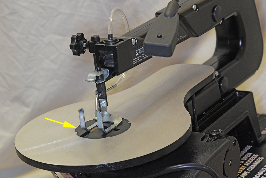
-
Harbor Freight 16" variable speed scroll saw
Dr PR replied to Dr PR's topic in Modeling tools and Workshop Equipment
I should also add that I bought the Harbor Freight foot switch - rated for 15 AMPs. It works, but the base is molded plastic and not metal. The foot switch is definitely worth the money. It allows you to turn off the power immediately if the blade jams, or if you just want to reposition the work piece without the blade moving. I wouldn't want to work with the saw without it. -
Harbor Freight Combination belt and 5" disc sander.
Dr PR replied to Dr PR's topic in Modeling tools and Workshop Equipment
Keith, Here across the pond Home Depot carries a pretty wide selection of 5 inch sanding discs. Maybe they have some other sanders that use this size disc - hand held rotary sander, disc to fit into an electric drill, or oscillating sander??- 8 replies
-
- 3
-
-
- belt sander
- disc sander
- (and 1 more)
-
Harbor Freight Combination belt and 5" disc sander.
Dr PR replied to Dr PR's topic in Modeling tools and Workshop Equipment
Keith, I was wondering how to remove the stick-on discs. I tried flexing the tables and they are both pretty sturdy on the unit I have. But I wonder if extended vibration might loosen the handles that hold them at the desired angle - to be seen. And the miter gauge does leave a lot to be desired! I used the sander today to trim 21 bulkheads for a plank-on-bulkhead model I am starting. I used the belt and it worked well. The 80 grit belt is pretty aggressive and can remove wood fast. Captain Vader is right about the vacuum ports. They are 1.5 inches (38 mm) inside diameter - too large for the hose on my portable vacuum cleaner. They are probably intended for the larger hose on some shop vacuums.- 8 replies
-
- 3
-
-
- belt sander
- disc sander
- (and 1 more)
-
Harbor Freight 16" variable speed scroll saw
Dr PR replied to Dr PR's topic in Modeling tools and Workshop Equipment
Mark, Thanks. I was wondering what kind of wax to use. I do hold the pieces down when cutting. I think the foot is just a safety measure in case the blade jams in the work piece -
USS Constitution by mtbediz - 1:76
Dr PR replied to mtbediz's topic in - Build logs for subjects built 1751 - 1800
You are building a beautiful model! -
Thanks, everyone. The saw cuts were a bit outside the line. Today I sanded the parts to the line. I plan to mount the forward bulkheads with the paper pattern on the aft side, and the after bulkheads with the pattern on the front side. Then when I fair the edges to the curvature of the hull I will try to leave the pattern lines. That is the way I designed it, with the bulkhead dimensions to the inside of the planking. Now the real challenge begins. The center frame/keel will be 28 inches (711 mm) long. Cutting it out of plywood sheets 24 inches (609 mm) long will be a challenge on a scroll saw with only 16 inches (406 mm) clearance! There are lots of curves and slots for 21 bulkheads.
- 492 replies
-
- 5
-
-
- minesweeper
- Cape
- (and 1 more)
-
My newest Challenge
Dr PR replied to James Flynn's topic in Building, Framing, Planking and plating a ships hull and deck
James, I think I understand why you want a big project that will take some time to build. A plank on frame model is a very big project with thousands of parts you must design and build, especially if you build to an uncommon scale where there are few, if any, pre-made parts available. Maybe some here were suggesting you try something easier because in your first post you said you were "kind of new to ship building." Many modelers "bite off more than they can chew" on their first attempt and become discouraged and quit. So they advise newbies to start with something simple so they don't become frustrated and give up. But in your latest posts you show that you aren't a beginner, and have a few builds under your belt. And you say you have the tools for scratch building. There is great satisfaction from working on a single large project for many years instead of a series of small builds, trying to build the one model to perfection. I spent 14 years making my CAD model of the USS Oklahoma City CLG-5, modeling everything down to rivets and screws as small as 3/16 inch (5 mm). Most of the time was spent obtaining data sheets and manuals for the equipment and missiles, and blueprints for the hull and superstructure. It gave me great satisfaction to build a model that had far greater detail and accuracy than most other models. I encourage you to take on your great project, and take pride in every piece that you build. And I hope you post your progress here. There is great knowledge in the members of the Forum and we are all willing to help solve problems as they come up. It is a learning experience for all of us. -
Carpet and button threads come in several sizes. I have some J & P Coates Dual Duty cotton covered polyester thread that is 0.007 inch (0.18 mm) diameter. It is very smooth without loose fiber "fuzzies." You should be able to find something like this at a sewing or fabric store.
-
Intakes usually have grilles to prevent fish and other large objects from being sucked in. They also prevent critters from crawling in and setting up house while the vessel is in port. Outlets often do not have grills, especially if they are constantly discharging even while the vessel is in port (engine cooling water, etc.).
-
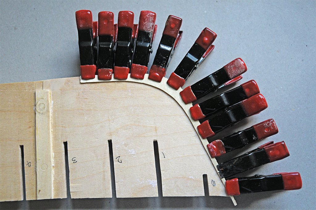
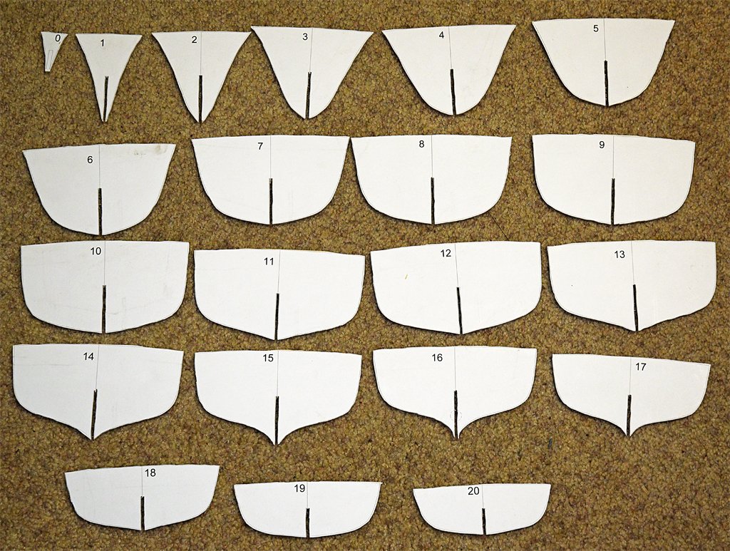
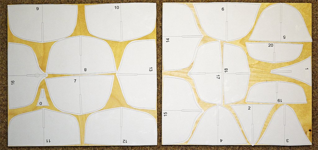
I have bulkheads! I used a scroll saw to cut the 21 bulkheads from 1/8 inch (3.2 mm) six ply basswood plywood from SIG Manufacturing. I printed the patterns on paper and then cut out each piece. These were glued to two 12 x 12 inch (305 x 305 mm) plywood sheets using an Elmer's "All Purpose Glue Stick." This was recommended in another thread on the Forum and it worked well. The pieces can be repositioned for a few minutes after applying the glue, and after half an hour the paper was stuck to the wood tightly. The paper did not lift from the wood while sawing. I used a 10 tooth per inch saw blade and ran the saw at 1650 strokes per minute. It took less than two hours to cut the pieces, feeding the wood into the blade slowly so the blade didn't bend or twist. This is just a rough cut close to the lines. I will trim the pieces to the final size with a sander, sandpaper and files. The slots for the pieces to fit over the center frame will be widened to 1/8 inch (3.2 mm) with a file to create a slip fit over the 1/8 inch thick center frame.
- 492 replies
-
- 8
-
-
- minesweeper
- Cape
- (and 1 more)
-
Harbor Freight 16" variable speed scroll saw
Dr PR replied to Dr PR's topic in Modeling tools and Workshop Equipment
I gave the Harbor Freight scroll saw its first test today. I cut 21 bulkheads out of two 12 x 12 inch (305 x 305 mm) sheets of 6 ply basswood plywood (SIG Manufacturing). The largest of the pieces in the photo was about 6 inches (152 mm) wide. I used the 10 tooth per inch blade and the highest motor speed. It took a little under two hours, advancing the part into the blade at a slow pace that didn't bend or twist the blade. I had no problems cutting the plywood - no broken blades and the blade did not tend to wander in this thin material. I found two two minor problems with the saw. The first is the workpiece foot - the part that lowers to hold down the part being cut. As delivered it doesn't contact the work piece evenly. Consequently it presses harder in some places than others allowing the piece to "chatter" up and down more in the loosest fit areas. I lowered it to allow a loose fit while still holding the part down to the table. It needs some bending to adjust it to fit parallel to the table and contact the work piece evenly. The other problem was pretty high friction between the plywood and the table surface. The table has a fairly coarsely brushed surface and that created noticeable friction against the plywood. I had to push the wood with significant force to move it over the table and rotate it. However, this drag may add a bit better control for moving the work piece. This must be a common problem because the instructions say to apply a light coat of paste wax to the table and buff it to allow the material to move smoothly. I didn't have the vacuum connected most of the time but just used it occasionally. There was some dust accumulation inside the machine. Not so much on the table surface. The fitting is on the front of the machine and the hose protruded out far enough to get in the way. This is a design defect in my opinion. Maybe I can add an elbow ("L" shaped) piece of PVC pipe so the hose runs off to the side.
-
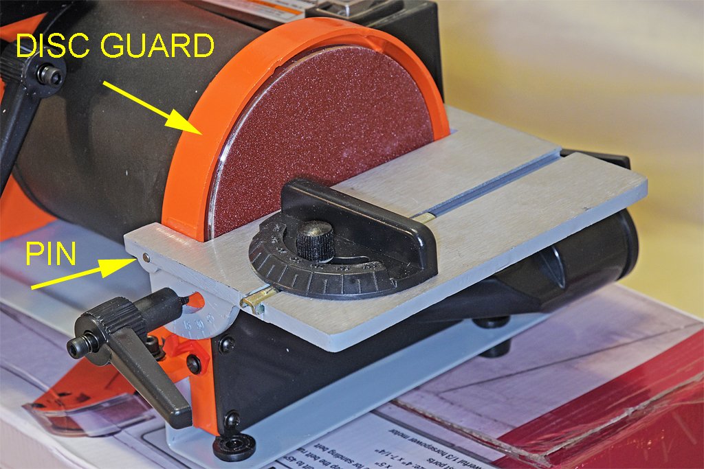
I have a need for a small disc and belt sander. Now that the Burns machines are no longer available I looked around and found the Harbor Freight #69033 sander. The two advantages of this machine are the cost ($70) and it uses common 5" sanding discs and a 30" x 1" sanding belt. There was quite a variety of replacement sanding discs and belts in stock at Harbor Freight and Home Depot. It is pretty quiet when running without sanding anything, and there is little vibration. It has a belt tensioner for the sanding belt. The tables to support the work piece tilt down for both the belt and disc sanders to allow angled work. It has two ports to attach vacuum holes to. It came out of the box partially disassembled in eight pieces, and there were no assembly instructions. This is not for someone who has trouble screwing the top back on a milk bottle! The instructions do tell how to replace the disc and belt, but there are a few pieces that need to be assembled in a specific order to put the thing together, and it isn't always obvious what to do first. And the clearances to get tools to some of the screws are pretty tight. But through trial and error I got it together in less than an hour. You need a set of metric Allen wrenches, a Phillips screwdriver, and about a 12 mm open end wrench. But there was one serious problem. The table for the disk sander is a separate piece, as are the two locking handles and the miter guide bar. To install the table you have to slip two pins (one on each end of the table) into slots in the metal disc guard. Then you screw the locking handles into the disc guard. However one pin (shown) would not fit into the slot in the guard. My calipers showed that the pin was about 0.020 inch (0.5 mm) wider than the slot. This was a casting issue, and there were several obvious blemishes in the cast metal guard. I used a square file to clear out the flash from the slot and then the pin did fit the slot. But, the table still wouldn't slide into place. Inspection showed that the pin had been pressed too far into the table, and the gap between the two pins was narrower than the distance between the slots! I used a jeweler's hammer to tap the pin back out a bit and the table finally slid into place. The sanding discs are the stick-on type. The single disc supplied with the sander is 80 grit, a bit coarser than I would like. The belt supplied with the unit was also 80 grit. The miter guide for the disc sander is a cast plastic piece with coarse angle indications, so you should use an accurate angle measuring tool and make test pieces to ensure that the angles are correct for your work. I really haven't used this machine much yet, but it will soon get a workout on my MSI build. I will report back later and tell how well it worked and describe any problems I might see.


- 8 replies
-
- 8
-
-
- belt sander
- disc sander
- (and 1 more)
-
For my MSI project I need to cut out 21 bulkheads and the central keel piece from 1/8 inch (3.18 mm) and 1/16 inch (1.59 mm) plywood. I could do this with my hand held coping saw, but it would mean many hours of work and sore arms afterward. I looked around for powered coping saws or scroll saws and decided to buy the Harbor Freight model 71113. I have no delusions about the "quality" of this machine - it is from Harbor Freight and is cheap Chinese junk. However, I only need it to work for a relatively few hours. It is definitely not good enough for someone who uses a scroll saw frequently! The main advantage for this product is the cost - $109.00. That isn't a huge expense for a modelling project. I am using $120 worth of scale rope and blocks on my Albatros project! The cast metal work table is 10" diameter with a 16" clearance (almost all the parts of the machine are metal). The table can be tilted up to 45 degrees for angled cuts. It has a LED work light that can be positioned near the cutting area, and an air blower bellows to clear dust from the work area. There is a place to connect a vacuum hose to remove saw dust. Changing blades is pretty simple - one side opens and hinges down out of the way to allow easy access to the lower blade holder. It has a blade tensioner. It is surprisingly low noise when running without cutting anything, and there is little vibration. It has a speed control to vary from 550 strokes per minute (metals and plastics) to 1650 strokes per minute for wood. It came out of the box completely assembled - you just have to position the table and tighten the locking knob to complete the "setup." A big advantage of this saw is that it uses standard 5" scroll saw blades made by many manufacturers. I looked at the Dremel scroll saw and the major disadvantage is that you can't find replacement 3" blades anywhere except the Dremel web site, you have to buy an assortment of blades and not just the one you want to use, and shipping costs are greater than blade costs (also, the Dremel saw is mostly plastic and just looks flimsy)! Harbor Freight has 5" blade packages in stock locally, although they are assortments of five different types, and they don't offer packages of just the type you need. Home Depot does offer quite a selection of 5" blade types and packages of several blades of a single type. Most of the reviews on line are good. As usual there are people complaining that they break blades and it won't cut really thick pieces (>2 inch (5 cm) thick) without the blade wandering, etc. Basically these people don't know how to use the tool and are trying to use it beyond its capabilities. It is a cheap tool for use on light jobs. Many reviews say it cuts 1/2 inch (12 mm) wood, 1/4 inch (5 mm) plastic and thin soft metals (no steel). I haven't used it for anything serious yet, but soon will give it a workout on my MSI project. I am posting this now to describe the tool, and I will follow up later with a report of how well it works and any difficulties I encounter. Note: Home depot offers several varieties of this same scroll saw - same castings, same specs, etc., but with slightly different "accessories." For example, they have this same model but without the work light for about $10 less than the Harbor Freight model, and another model with the work light for about $10 more than the Harbor Freight version.