
HOLIDAY DONATION DRIVE - SUPPORT MSW - DO YOUR PART TO KEEP THIS GREAT FORUM GOING! (Only 13 donations so far - C'mon guys!)
×


Dr PR
-
Posts
2,406 -
Joined
-
Last visited
Content Type
Profiles
Forums
Gallery
Events
Everything posted by Dr PR
-
 ZB, Thanks for the information about tacking the gaff topsails. I was wondering how it was done. There as been some discussion and different ideas on other threads, but the videos you posted show the process nicely.
 -
Bob, Thanks for the comments about shellac's shelf life. I have wondered if this was just rumor. I have seen other posts from folks who have used containers of shellac that have been around for many years. Like you said, I suspect that solvent evaporation is the most serious problem, and that is easily solved by adding more ethanol. And cheap ethanol is easy to find. It is sold as 95% denatured alcohol fuel for stoves, with 5% methanol to discourage it from being ingested.
-
Looking great, as always! That Jackyard topsail is huge! I read in John Leather's Gaff Rig Handbook that the jackyard evolved as a means of getting around some type rules for racing. It allowed the area of the spar gaff topsail to be expanded greatly without violating the rules as written. He said some jackyard topsails had greater area than the main sail! You would have to be quick handling those things if a sudden squall blew up. It is a beautiful model!
-
Seats of Ease
Dr PR replied to stuglo's topic in Discussion for a Ship's Deck Furniture, Guns, boats and other Fittings
There are other threads on the forum discussion seats of ease. Someone posted a link to the attached thesis on the subject. Seats of Ease Simmons-MA1985.pdf -
I have started experimenting with shellac and I like working with it. I have both a spray can (wasteful) and flakes, both clear and dewaxed. It seals the wood nicely with a mat or satin finish that I like, and it doesn't stink. I have also painted over it with acrylics with good success. One caution about shellac. After it is mixed it has a limited shelf life of only a few months. That is why many modellers get the flakes and mix them in alcohol (95% ethanol, available cheap as a fuel) when needed. Allow a day or two for the flakes to dissolve completely. There are extensive discussions about shellac and how to mix and use it on the Forum.
-
I have used lead bearing solders for at least 60 years, with no "toxic" effects. Lead is toxic if you eat it - as with the early lead soldered metal food containers. And it is toxic if you drink it - as with water delivered in lead pipes or copper pipes with lead solder joints. But you have to eat or drink a lot of it. Just momentarily handling lead solders is not hazardous. Soldering does not produce hazardous lead vapors. Maybe if you handled lead or soldered for hours daily for years you might suffer toxic effects. But occasional hobby work is not going to cause problems. I do like to have adequate ventilation to remove the smoke and fumes from the fluxes used with soldering. They are probably more "dangerous" than the lead. And it is a good idea to wash your hands with soap after handling soldered pieces because brass, copper, tin and lead are all metals with possible toxic side effects. The problem with lead solders is that objects carrying lead soldered parts (electronics circuit boards, etc.) are/were being disposed of in city dumps where the lead can leach out into the water table. This is why lead bearing solders have been banned, not because they pose a direct hazard to people using them to solder things.
-
I have a 15 star/15 stripe flag (replica) that I was presented as part of a War of 1812 celebration at the Buffalo and Erie County Naval and Military Park in Buffalo, NY. A note that came with it said the flag was used May 1, 1795, through July 3, 1818. This would have been on Lake Erie and that area. The flag was 3x5 (actually 60 x 34 inches).

-
Capella, The motor control (fan control) you listed should work, but note that it is for brush type motors only and not brushless motors. But all the drills I have seen have brushes, especially the cheaper drills. Also, it is rated at 15 Amps and that is good enough for any motorized device that has a cord to plug into a wall socket on an ordinary household 3 prong 15 Amp 120 Volt AC circuit.
-
Electric motors are inductive loads - like electromagnets. These do some peculiar things (a non-engineering explanation) to the driving AC current. Light dimmers usually use a solid state switch called triac or silicon controlled rectifier (SCR). Operation of these devices is very dependent upon the characteristics of the AC current - as delivered by the AC power line - and are designed to drive resistive loads like light bulbs that don't mess with the characteristics of the current. If you try to drive a motor with a dimmer the results may be unpredictable and/or the dimmer may go up in a puff of smoke. The motor may overheat, and the dimmer may emit a lot of RF noise that interferes with television, radio and cell phones. There are some fairly inexpensive variable speed AC motor controllers that you can just plug the drill into without cutting the cord. Then you can plug these motor controllers into an off the shelf AC foot switch to interrupt power to the controller to stop the drill. And these things are wired correctly and UL/CSA approved so they won't burn your house down. I have an old (1980s) Dremel motor controller and foot switch I use to control AC motors.
-
Bob brings up an interesting point about "collector items." Some collectors prefer the dirt and grime be intact as an indication of the item's age. They say you ruin the value if you clean an old object. Other people prefer a shiny clean piece. You should just do what you like and not try to follow other people's rules. Personally, as a microbiologist, I find the idea of using saliva to "clean" things disgusting. To me something that has been spit on is just filthy! If you do try using a solvent (water, soap and water, alcohol, etc.) be careful. Those old paints might dissolve in the wash. So try it on an unexposed place first if you can find one.
-
You can find small multi-strand wire in jewelry supplies in hobby stores. I have some Beadalon brand 7 strand at 0.012", (0.30 mm) 0.015" (0.38 mm) and 0.018" (0.46 mm) diameter. I also have some nylon coated Cable Strand Corp. Acculon brand 3 strand at 0.012" (0.30 mm) diameter.
-
The Prince was a pretty ship. I'll be interested in seeing how you do on this. I understand the "ordinary" part. I am slowly completing a model that sat unfinished for at least 30 years.
-
sail plan for Ballahoo (Fish class) topsail schooner
Dr PR replied to georgeband's topic in Masting, rigging and sails
George, Very nice. I am following this with interest. I have worked out a preliminary belaying plan for my topsail schooner build, but I am not happy with the belaying point plan I have for the fore mast. Too many lines are crowded onto fife rails around the base of the fore mast. I have been considering a belaying pin ring or cleats around the mast to take the running ends of some of the tackles. Also I could use cleats on the shrouds for lines that do not have much strain on them when sails are set (clew lines bunt lines).- 22 replies
-
- 2
-

-
- caldercraft
- jotika
- (and 4 more)
-
Carriage Gun Rigging
Dr PR replied to Dr PR's topic in Discussion for a Ship's Deck Furniture, Guns, boats and other Fittings
Thanks to everyone for contributing to this discussion! There is a lot of good information here! -
Valeriy, Thanks. I did notice that you plated some parts with copper before nickle plating, and wondered if that was to get a more uniform nickle plating. But the real solution is to just be careful with the soldering. Using a minimum amount of solder helps, and a good liquid flux (I like citrus based fluxes) helps promote solder flow between pieces. I also have a resistance soldering machine and have experimented some with it. It has the advantage that heat is generated at the contact/solder point, reducing heating of adjacent parts and previous solder joints.
-
Valeriy, Thanks. I have used some rouges for polishing but I was interested in how you do it. Your results are beautiful! I have also puzzled over what to do when a bit of solder flows over visible areas on brass parts. The tin in the solder dissolves into the brass leaving a tin colored stain. Careful positioning of the solder areas to inside or non-visible places helps, but sometimes a visible solder fillet is necessary. Blackening and other coloring agents don't work evenly over these exposed high tin areas. But it seems you solve this problem by nickle plating the parts. The plating covers the brass and solder areas evenly. Looks like I will have to set up plating equipment. I already have power supplies and I was an undergraduate chemistry major so that part will be simple.
-
I will be happy to share any information I have on the blueprints, weapons, radars, directors and such. However the CAD model is in DesignCAD file format and the files are not compatible with other software, and I don't intend to spend more years trying to translate them. I do have a few STL files that I can share. These are from my 3D printing experiments. You can contact me by personal message on this Forum or through my contact page on my Okieboat web site: https://www.okieboat.com/Contact page.html
- 54 replies
-
- 3
-
-
- 3d cad
- cleveland class
- (and 1 more)
-
Ras, Thank you. That project turned out to be a very deep rabbit hole and it took me about 14 years to find my way out again! In addition to the blueprints from the Archives I had hundreds of photos I took on the ship and hundreds more that other OK City sailors sent me (plus tech manuals for the equipment, etc., etc.). I originally posted the CAD model build on the DesignCAD Forum (for the CAD program I use) over the 14 year period. That is where I first met Valeriy - a friend of his in Ukraine was building a model of the ship using the pictures I posted on the DesignCAD forum and he contacted me. I still want to build a 1:96 scale model of the USS Oklahoma City CLG-5, but right now I don't have the space or tools to do so. I started on one in 2005 but stopped when I realized I didn't have enough information to do a good job. So I dove down the rabbit hole. You can see some photos of that early attempt here: https://www.okieboat.com/Ship model page.html I had planned to use styrene and Plexiglas for the main structural parts and brass for the details. Recently I have obtained a 3D printer and have been experimenting with that, but it just isn't good enough (too fragile and too much pixelation/jaggies) for what I want to do at 1:96 scale. And I have seen Valeriy's work (and Kieth Aug and others on the Ship Model Forum) and that has raised the bar for what I would like to achieve. Now I am planning a workshop addition to my garage so I will have a place to work, and accumulate the tools needed to do good work. But don't hold your breath. It may be years before I resume work on the real model.
- 54 replies
-
- 3
-
-
- 3d cad
- cleveland class
- (and 1 more)
-
Valeriy, I just spent the day re-reading your log from start to here to refresh my memory of your building techniques. I wanted to see how you get such beautiful finishes on your metal parts. You said you used Zapon varnish on the brass parts, and you nickle plate a lot of the metal. How do you polish the metal before paining or plating it? Does the metal plating just naturally produce a smooth shiny surface?
-
There was also a Black Pearl yacht in Newport, Rhode Island back in the 1960s.
-
Work bench width and height - any recommendations?
Dr PR replied to Dr PR's topic in Modeling tools and Workshop Equipment
More good ideas! Thanks! Steve, I will have a contractor do the main work and that will have to go through the city engineering department for permits, etc. What I have drawn is just a conceptual drawing. The city's inspectors are pretty thorough. Insulation is important. We rarely get down to freezing here, and rarely over 90F in the summer, so it is pretty mild. But the uninsulated garage gets down into the high 30sF (~4C) in winter and into the 90sF (~35C) in summer. So I'll need good insulation to make the space usable year round, and for the benefit of the machine tools. I had not thought of insulation beneath the concrete floor. I have never seen that used here. It might compress and allow the concrete to break. I'll see what the contractors recommend. I think I recall reading in our building codes that at least one window is required since this will be an "occupied" space (as opposed to closets and such). Having a flow of fresh air when it is nice outside will be good. -
Lateen. You can see pictures of his build in the llink he posted. I have no idea how the lateen sail was used.
-
Work bench width and height - any recommendations?
Dr PR replied to Dr PR's topic in Modeling tools and Workshop Equipment
Thanks again, everyone. The floor will be reinforced concrete continuous with the floor of the garage. Who knows, someone may want to work on something heavy in there some day. I will need mats on the floor, at least in front of machines (mill, lathe) that I will be standing in front of for long periods. I'll use adjustable height stools or chairs that I can move in front of other work areas. I like the way the bench was constructed in the video vaddoc linked to. There will be a "L" shaped bench across the end of the room and along the short side where the outside tool locker will be. I think 30" (76 cm) deep will be about right. This bench will be about 12 feet (3.66 meters) on the long side and ?? feet (?? meters) on the short leg. Here is an overhead view of what I have in mind: It is a small "retirement" house, with a single car garage. The workshop is an extension of the garage. The wall with the door is 13.75 feet (4.2 meters) long and the wall along the long side of the fixed bench is 11.65 feet (3.55 meters) long, inside dimensions. You can see the 6.5 foot long (2 meter) CLG hull on the moveable bench. The benches are 30 inches (76 cm) deep. The "tool locker" is an outside accessible store room for a lawn mower and gardening tools. They currently occupy the space in the garage between the end of the cabinets and the upper wall in the picture. When I put in the doorway I will need somewhere to put all those things. I will put the vacuum and air compressor in the cabinets in the garage and plumb them into the work room. That way the noise will not be in the work room. The shop isn't very large but it is a major improvement. Right now I do most of my work on the kitchen table with hand tools. Now I just need to draw up 2D plans and get some bids from contractors. I'm sure there will be changes. I will need at least one window. I have been building and remodeling houses since I was a kid, and I suppose I could do most of this except the concrete work. But I'll have a contractor build the foundation, framing, exterior walls and roof. That's a caveat to my age (and my significant other). I can finish the interior myself.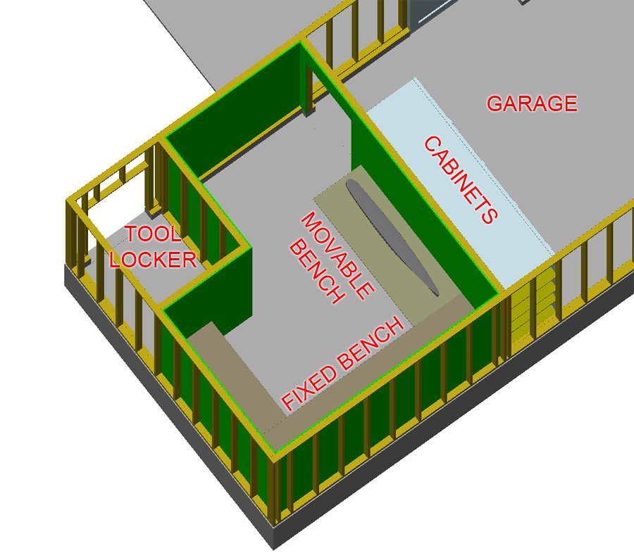
-
Work bench width and height - any recommendations?
Dr PR replied to Dr PR's topic in Modeling tools and Workshop Equipment
Jaeger and Bob, Excellent suggestions! I had been thinking about a bunch of AC outlets below the front edge of the benches, alternating with the vacuum outlets. Your point about not dragging power cords across the bench top is well taken! The idea of running some 220 VAC to outlets above the benches is also a pretty easy thing to add. There are already 220 VAC circuits in the main breaker panel in the garage. One thing to keep in mind before planning a lot of separate AC circuits - have you priced Romex lately? I recently installed a whole house fan in the attic and I needed about 150 feet of 14/2 Romex and it was going to cost a small fortune. Fortunately I discovered most of a 250 foot roll hiding in the back of the garage storage, left over from a wiring project long ago. I planned to put the vacuum inside a cabinet to reduce the noise. I still wanted to be able to pull it out and roll it around so I could use it in the garage also. However, on the other side of the common wall between the shop and garage is a large storage cabinet that I could put the vacuum in! No need for the wireless on/off. I can just put a switched AC outlet in the garage cabinet. A hole can run through the wall from the vacuum to the vacuum manifold. I do plan to have the shop floor level with the garage floor, with a 36" door between the shop and garage. I will need to roll some pretty heavy tools and boxes into the shop. I had also thought about having a roll-around work bench so I could get at all sides of a large model without having to turn it around. One of the benches will be about 90 inches (228 cm) long. I suppose I could make it movable. It is the one closest to the door and is where I was thinking of putting the model. I would attach the AC outlets to the wall above where it would normally be positioned. I plan to put pegboard above these wall outlets. These would remain on the wall when the bench is moved. The room isn't very large so I will have to plan the size of a moveable work bench so it can be turned around without having to roll it out to the garage to turn it and then back into the shop. I just tried it in the CAD model and an 84" x 30" (213 x 76 cm) table can be rotated 360 degrees in the shop if I champfer the corners about 6 inches (15 cm)!