
HOLIDAY DONATION DRIVE - SUPPORT MSW - DO YOUR PART TO KEEP THIS GREAT FORUM GOING! (Only 13 donations so far - C'mon guys!)
×


Dr PR
-
Posts
2,406 -
Joined
-
Last visited
Content Type
Profiles
Forums
Gallery
Events
Everything posted by Dr PR
-

Work bench width and height - any recommendations?
Dr PR replied to Dr PR's topic in Modeling tools and Workshop Equipment
Thanks for all the ideas. I am planning an extension to the back of my garage for the work shop. It will have a "L" shaped shop area, with an inset storage closet with an outside door for storing a lawn mower and gardening tools. The space will be insulated and have its own heating and possibly air conditioning and dehumidifier (this is Oregon and it can rain for months on end). Right now the garage gets too cold in winter to work out there, and pretty warm in summer. It wouldn't be a good environment for machine tools. I am thinking of built in benches along three walls - a "U" shape - with plenty of room in the middle for moving around. I like Jaeger's suggestion to make the benches as deep as I can comfortably reach. As far as bench height is concerned, 36" - 39" (91 cm - 99 cm) is about elbow height and seems to be a comfortable height for standing. It is low enough to allow me to lean over a lathe or other tool for making adjustments. Steve's idea of making it the same height as the deck of the table saw is really good! I want to get a table saw on casters for large scale house work. It will be stored along the fourth wall along with a roll-around tool cabinet. I can roll it into the garage area for working on long pieces,such as making work benches. It also will be handy for cutting large stock for model work. I will have some shelves below the benches and maybe a space for a roll-around tool cabinet.These will be set back enough that I can sit at the bench on a stool. I will definitely have drawers to hold accessories for each tool. Shelves or cabinets will be mounted to the walls above some of the benches, allowing room for taller tools like a milling machine. Lights will be mounted to the bottom of the shelves/cabinets. I was thinking of having AC outlets along the back of the benches at least every two feet. Outlets and wiring are pretty inexpensive relative to the costs of the rest of the project. Each bench will have its own AC circuits and breakers - at least two per bench. I have 17 unused 15 Amp breaker positions in the house 200 Amp breaker panel in the garage close to the shop extension, so I can wire a lot of individual 15 Amp circuits and gang breakers for 30 Amp circuits. I am also considering a vacuum manifold under the front edge of the bench. A shop vacuum will be stored under one of the benches and will normally have a hose attached to the manifold. The manifold will have openings under the front edge of the bench that normally will be covered. This will allow plugging an ordinary vacuum cleaner hose into the opening and into or near any tools that make dust or chips (sander, lathe, mill). The vacuum AC circuit will have its own power switch(s) on each bench section. I can still roll the vacuum out into the workspace or garage. I have a fair amount of experience with lathes and milling machines - the large industrial machines. I will have the small "hobby" machines, but the rules for working with them will be the same. You need plenty of room for the table on a milling machine to move back and forth and for working on the ends of extra long pieces. A lathe should have lots of room behind the chuck end so you can feed long stock through the center of the chuck/collet. I am designing the shop on my CAD system, and I have a 6 1/2 foot (2 meters) long 1:96 scale model of a 610 foot cruiser hull in the plan so I can make room for a big model. This is actually one of the things that made me decide to add on the shop addition. I need lots of room to build the real USS Oklahoma City CLG-5 model. Any other models will certainly be smaller than that! **** Here is another question. What tools should be located near each other for working convenience. For example I can see where having a bench sander located close to a bench saw would save steps moving between them. A metal shear and bending tool probably should be near the milling machine. Any other suggestions? -
I am planning an addition to my garage for a workshop. I have looked at commercially available work benches and they vary from 20 inches (50 cm) wide to 36 inches (91 cm). Height ranges from 30 inches (76 cm) to 39 inches (99 cm). I am planning for a variety of small tools including a lathe, milling machine, sander, metal press, etc. I have dimensions for a variety of these tools and all will fit on a 24 inch (61 cm) wide bench. But I would appreciate advice from those of you with experience with such tools as to how wide and high the benches should be. I will likely be building all of the benches with wood myself, so I can make any size and height.
-
Here's my two cents - and that's about all it is really worth. I started modelling in the early '50s with simple balsa airplane kits (before plastic came along). They were mediocre at best. Next came the early plastic models that seemed to be wonderfully detailed at the time, but pretty crude by modern standards. They were a LOT easier to build, with MUCH better results. At one time I had a fleet of 15-20 plastic ship models - almost every penny of my allowance. Then I started building wooden models from scratch in the late '50s, with just a few sheets and sticks of aircraft balsa (all that was available from hobby shops at the time). I wanted to model vessels that weren't available in plastic. Scratch building every last piece - without any decent plans - was quite a challenge, but a lot of fun. But those early models really weren't much to look at and nowhere near accurate. My first kit was Billings Santa Maria in 1969. After scratch building it seemed like doing a paint by number painting. Not very challenging, but I learned a lot about wood ship model building, especially planking! With that kit many of the parts had to be cut from sheets of plywood that had the outlines printed on. I built a couple other kits, and added increasing amounts of hand made details. I have several more in my stash. Now you can get kits with all the parts pre-cut and shaped. They seem to me to be like 3D jigsaw puzzles. I am now kit bashing a kit of one vessel into something different, a blend of kit and scratch building. And I am 3D printing hundreds of parts parts for a large (6 1/2 foot) scratch built metal and plastic model based on a commercially available fiberglass hull. Again, it will be a ship for which no kit is available, either in wood or plastic. All of the parts (printed or not) will be from my CAD model of the ship. And I am working on plans for a wooden model of a wooden minesweeper. Again, every piece will be hand made. So I have tried a little of everything, and I think there is a place for all of these versions in our hobby.
-
An adaptation of Johnny's idea would be to saw a groove vertically above the slot for the keel on the face of the part on the inside of the curve. Don't cut all the way through the bulkhead. Just cut about half way through the part or enough to allow you to bend the part around the groove. It looks like t is three layer plywood so cut down through two layers. Then bend the part flat. Be careful - if it is an old kit the wood will be brittle and might break (but that would be easy to repair). Now lay it flat with the cut side up and weights on the outer edges to hold them down. Glue a wide wood patch over the cut from just above the keel notch to just below the deck. This should give you a bulkhead of the proper dimensions with no significant curvature.
-
A friend, William McCash, wrote the book "Bombs over Brookings" about Nobuo Fujita and the attacks on the Oregon coast. The aerial attacks weren't on towns or forts, but in the Coast Range forests. The idea was to start forest fires to destroy the timber resource. It failed. No significant fire resulted. The Coast Range is wet. Very wet. Lots of fog and rain. The rain isn't heavy - what we called "sprinkles" back east - but it is continuous in the winter months. There have been years when it clouded up and started raining in late October and we didn't see clear skies until April or May. I used to tell people that any time the ground got dry in Oregon it was a drought. However, in the last 20 years it has been much dryer, and we have had some horrendous forest fires. Fujita's attacks were just 75 years ahead of time.
-
There was a very good story with lots of photos about these submarines in Sea Classics magazine. It also has a first hand account of the pilot from I-25 Flying Officer Fujita who bombed the Oregon coast on 9 September 1942. Sea Classics, Vol.4, No. 1,January 1971, page 44
-
Auto login failure
Dr PR replied to Dr PR's topic in Using the MSW forum - **NO MODELING CONTENT IN THIS SUB-FORUM**
The problem resolved itself a couple days ago. I use the Thunderbird browser, and occasionally the programmers screw up something when they post updates. I had checked Thunderbird's list of auto logons and the user ID and passwords were all there, but the program just wasn't using them. They occasionally do stupid things to improve "security" that prevent users from doing things like opening PDF files and such. Eventually they receive feedback (although this is almost impossible to accomplish) and correct the problems. My guess is that is what happened with the auto logon failure. There was a new update recently (Monday?) and auto logins started working on MSW and other forums. So that seems to be the answer. -
Roger, Thanks for pointing that out. I had noticed those odd "bilge keels" and wasn't aware of keel condensers. A quick search brought me up to date. l learn something new every day (at least I hope to)!
-
Decal Solution Questions
Dr PR replied to hof00's topic in Painting, finishing and weathering products and techniques
You might try posting the question on model railroading forums. They use a lot of decals on engines and rail cars. I have used a decal wetting/setting solution in the past but I don't remember much about it, and I don't recall any "super strong" versions. I certainly am not an expert with decals! -
Dowmer, Thanks. This build started out to be a theoretical revenue cutter of about 1815, but it seems to be morphing into a similar vessel of the 1820s or 1830s. All the choices do slow things down. I may be slow but that is a good thing because I might be going the wrong direction.
-
I have made a command decision! Although there are a number of inaccuracies and some speculation in this build, I have tried to be accurate where possible. But model ship colors for vessels prior to the mid 1800s are mostly pure guesswork. In some cases there are some published standards or regulations, but mostly it seems, like everything else on ships of earlier periods, things were done as things were done. The colors of masts, spars and tops were not well documented before photography came along, and even then the early black and white photos tell little about colors, just shades of grey. For the early 1800s masts seem to have been wood colored, perhaps with varnish or oil finishes. But some were painted. References like Nelson's orders to paint mast bands the same color as the masts before the Battle of Trafalgar tell us that, but don't say what colors were used for the masts. I have examined many drawings and paintings of schooners in the early to mid 1800s and have found nothing that shows colors. In a very few cases the tops of early 1800s schooners appear to have been painted white. But some tops were dark, and masts were always lighter. It seems to have been the practice in the British Navy to paint tops black (at least some contemporary models have dark or black tops) and many American vessels followed British practice. Later in the mid 1800s white mast tops became common. Perhaps this happened because the British and American navies changed the color of the band on the hull along the gun ports from yellow to white. The ready availability of white paint may have led to it being used elsewhere, such as deck furniture and mast tops. For whatever reason white was normal on these parts after the mid 1800s. I would have preferred white tops because it shows details better. But I would have had to paint the mast bands and eye bolts black. And my model is of an early 1800s vessel, probably before white came into use (it has yellow gun port bands). So I decided to go with black tops. Mast and spar color was another matter. But in reviewing several discussions on the forum I came across a reference to the introduction of straw colored paint sometime in the early to mid 1800s. By the end of that century masts and funnels, and even parts of superstructures, were being painted straw color. Look at the ships of the Great White Fleet. And the straw color has continued to be used throughout the 20th century and even until today on some ships of the US Coast Guard (the Eagle, for example). And since revenue cutters were part of the Revenue Service, the precursor to the Coast Guard, it seemed straw colored masts and spars were appropriate. I have always liked the colors on Coast Guard vessels. So black tops and straw colored spars it is in Phil's Revenue Service! And as was common before any standard colors were defined, I mixed some brown, yellow and white paints to make my own straw color.
-
You are absolutely correct. In photography lighting is the most important part of getting a good photo. I do a lot of outdoor wildflower photography and cloudy bright days are the best because there is a lot of white light (from the clouds) from all directions, not much blue light (from the clear sky), and no harsh shadows. Indoors I try to simulate this with a diffuse white light. Controlling the shadows is key to bringing out textures, curves and such.
-
Valeriy, When you started these boats I assumed they were personnel boats - the captains gig and such. But with the armament, and not a lot of cabin space for personnel, I wonder how these boats were used? Not only are your modelling skills excellent, but your photographic skills are equally good. This allows us to appreciate the quality of your work. Photography is one of my hobbies, so I was wondering what camera and lens you are using to photograph your models?
-
Auto login failure
Dr PR replied to Dr PR's topic in Using the MSW forum - **NO MODELING CONTENT IN THIS SUB-FORUM**
Any further suggestions for getting auto login to work on the forum? Nothing I have tried so far has gotten it to work. -
I have searched through many books looking for guidance for paint colors on ships. So far I haven't found much. Large expensive ships were tricked out with details and colors. Smaller ships, especially merchant vessels, were often pretty drab. As others have said, the colors seem to have been up to the Captain or ship owner. Cost was a factor, as was availability of paints. Black, white, yellow, brown and red seem to have been common in the mid to late 1700s. Some blue and green started appearing in the 1800s. I wonder if the red paint was actually red lead? This was used on exposed wood to prevent rotting. White lead mixed with tallow was an inexpensive way to protect the underwater parts of hulls. Copper sheeting was much more expensive. Brown may have been just the color of oiled or greased wood, especially on the masts of fore-and-aft vessels with mast bands for the sails. In the first quarter of the 1800s white started replacing the yellow on hull exteriors. By the mid 1800s deck furniture, mast heads and other details were painted white. My opinion (and it is just that) is that the modeller can do whatever seems best if there is no specific period information about the colors used on a particular ship at a particular time.
-
Les, First, you need a tight fit into the hole. You need to get a smaller drill bit - 0.39 mm or 0.40 mm. As you noticed, they will drill slightly larger diameter holes than the bit diameter. I usually bend slight curves into the shaft so the part goes in with a press fit. You can use needle nose pliers to push the part into the hole. I have also just used the shaft of drill bits slightly smaller diameter than the hole (1 mm) in the eye. It depends upon how much clearance you have around the place the part is being fitted. I use a needle point to put a small amount of glue into the hole and immediately wipe off any excess. I also wet the shaft of the eye bolt with a small amount of glue before inserting it into the hole. I wouldn't use CA because it will soak into the wood around the hole. This doesn't matter if you are going to paint the wood, but it will prevent stain from soaking in and leave a discoloration around the hole. I use Duco cement, white glue (Elmer's) or PVA. Whatever can be wiped off without staining the wood. Epoxy is even better because if fills the hole with a solid plug that is stronger than the wood. The combination of glue and a tight fit will hold against moderate tension on the rigging - but don't press your luck! Rigging doesn't need to be very tight, just enough to pull it taut.
-
Auto login failure
Dr PR replied to Dr PR's topic in Using the MSW forum - **NO MODELING CONTENT IN THIS SUB-FORUM**
Robert, I can edit the login IDs and passwords for different web sites in Firefox. I found three different login names for Model Ship World and deleted two that I don't recall ever using - or creating. Mark, I do not have "Always use private browsing mode" enabled for "Browsing History." I don't know if there are other "private" modes. -
A while back I was having trouble editing/adding to some of my posts. The recommendation was to clear my browser cookies. Well now I can edit things, BUT ... Auto login no longer works, not only on Model Ship World but also on some other forums. This happens on the first time I try to access the forum after my laptop has been shut down. After that, the auto login works every time until the machine is shut down again (every evening). When I do try to log on I am presented with two name/password options. But when I look at settings only one is shown. Note: I found the problem here. The browser (Firefox) actually had three different logins for Model Ship World - one without a name. I deleted all but the one I normally use. It isn't a big deal, but a bit of a nuisance, especially since it used to log on automatically every time I accessed the forum, even after the machine had been turned off. Note: I do have the "Remember me" option selected in the login dialog. Any suggestions?
-
I had to pipe in on this one. Back in the '50s and '60s I bought all sorts of chemicals in our local drug store and acids (sulfuric and hydrochloric) were available at auto parts stores. I did blow up a few things and burned a few. One day the druggist asked what I was going to do with some of the stuff I was buying. He said my father had told him he wouldn't be surprised to come home someday and find a hole in the side of the house. But our (the kid across the street and me) biggest boondoggle was experiments with rocket fuels for a science fair project. We made a rocket from a 2 inch (5 cm) diameter 18 inch (47 cm) long piece of steel automobile exhaust pipe. It had a machined steel nozzle in the back and a wooden nose plug. The rocket was suspended beneath a long piece of fence wire pulled tight between two trees some distance apart, with a heavy blanket at the far end to stop the rocket. Our experiment was to measure the time of "flight" between the two trees with a stopwatch and rate different rocket fuels accordingly. The fuels we made really weren't very impressive. We tried filling the rocket with home made gunpowder and it just fizzled and sputtered. So we went down to the local sporting goods store to buy some real gunpowder. The fellow said he wasn't allowed to sell gunpowder to minors. But he did sell us cans of shotgun and pistol powder (nitrocellulose soaked with nitroglycerine) - basically plastic explosive in pellet form. We decided to try a quarter load of pistol powder in the "rocket". The other kid's dad lit our home made fuse and ran behind the house. I was watching from a distance. I saw the flash first and then the BANG hit me. Later a kid who lived all the way across town told me he heard the explosion. The rocket nozzle cut an inch deep (2.5 cm) plug out of one tree. We found shrapnel bits all over the neighborhood. We couldn't find the nose piece until we walked the probable trajectory across the street and through a field. It had hit and split a fence post about a city block away. Good thing the post stopped it because it was aimed at a window in a restaurant across the street! Fortunately none of the shrapnel did any damage to nearby houses and no one was hurt. So our science fair project was over when the rocket blew up. But it caused me to have sympathy for the guys at Cape Canaveral who routinely blew up really big rockets back in those days. Kids now days lead dull lives. Only virtual explosions on cell phones.
-
Mark, I have some tiny brass nails with round/domed heads that are 7, 10 and 12 mm long. The diameter of the wire in the 7mm parts is 0.020" (0.5 mm) and the heads are 0.052" diameter (1.3 mm). This is 2.5 inches (6.35 cm) at 1:48 scale. I have been using them to represent round bolt heads on my 1:48 scale build and they look respectable. I have had them for years (pre Internet) and cannot remember where I got them. But it was a hobby shop or mail order shop that carried hobby supplies. Doll house stores might carry them. Some ship model kits come with these tiny brass nails, so you might search through kit manufacturer's web sites. Small nails with domed heads are also called escutcheon pins.
-
Spritsail yards on Niagara and Constitution
Dr PR replied to gak1965's topic in Masting, rigging and sails
Some vessels used the spritsail yards as spreaders - similar to how crosstrees and spreaders are used in topmasts to support the shrouds and stays. Jib boom stays were often routed through the ends of the spritsail yards to create a more stable triangular support for the ends of the jib boom. -
Mango, With wood strips you can soak them multiple times. However your bulwarks appear to be plywood Soaking might cause the plys to delaminate. The kinks at the bow gun ports are a problem. The bulwark strip is much weaker at the ports and that causes the kink when the strip is bent. One way to correct this is to place another strip of wood without holes outboard to the bulwark strip. This shouldn't be glued to the bulwarks, but just bent along with the bulwarks and clamped to the bulkhead extensions (the posts inside the bulwark strip). You may also need to clamp the bulwark strip to this outer piece at each side of the gun port to eliminate the kink. You shouldn't have any waviness down the length of the bulwarks. If you do the frames have not been properly faired. Use a long sanding block to shape the outer edges of the bulkheads to remove any materiel that is too "high" (causing outward bulge)s. You can glue thin wood strips to any bulwarks that are too low (causing inward curves in the bulwarks). The normal method to test the fairing of the bulkheads is to use a thin strip of wood what is pinned/clamped to all bulwarks and look down the hull length for waves along the strip. Keep removing or adding material to the bulwarks until this test strip has a smooth (fair) curve along the entire length of the hull.
- 1 reply
-
- 4
-

-
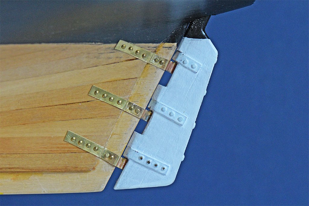
Today I decided to correct a blunder I made earlier on. I swapped the gudgeons and pintles on the rudder! I knew better but got involved with making the pieces and put the pintles on the stern post instead of the rudder! What a lubber's mistake!! I was so embarrassed! Now the pintles are on the rudder where they should be. I also added more appropriate strapping for the gudgeons. Now I can sleep easier knowing that mistake has been corrected!
-
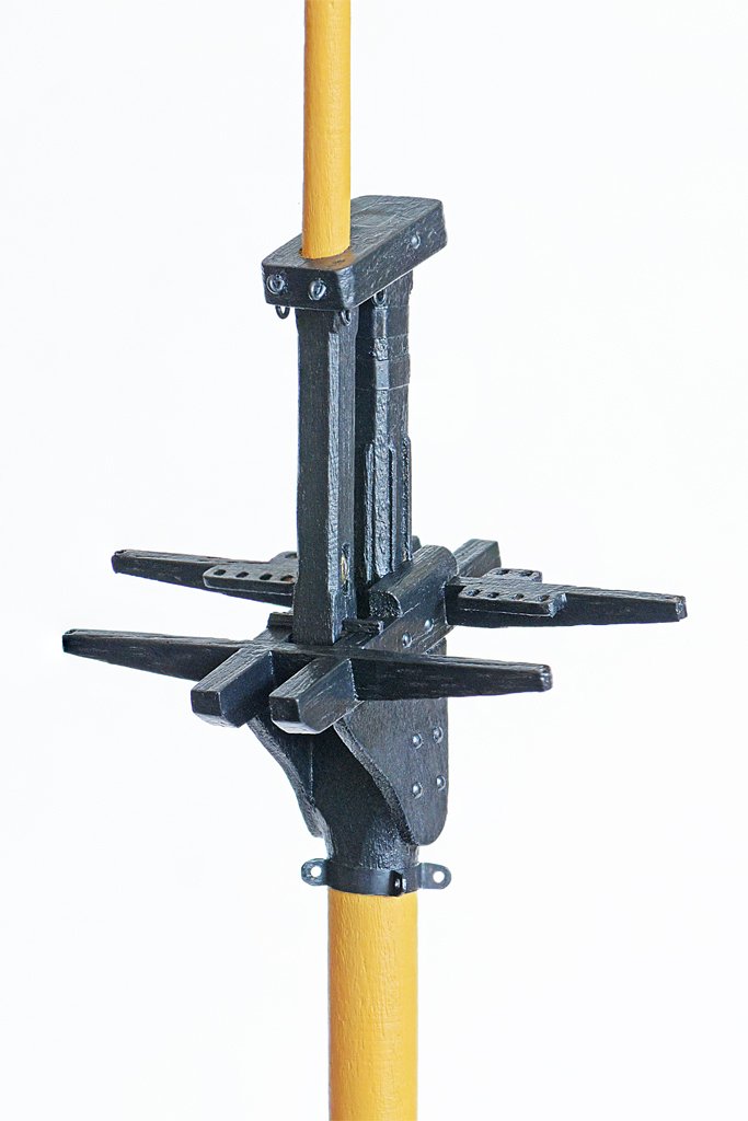
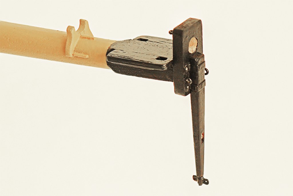
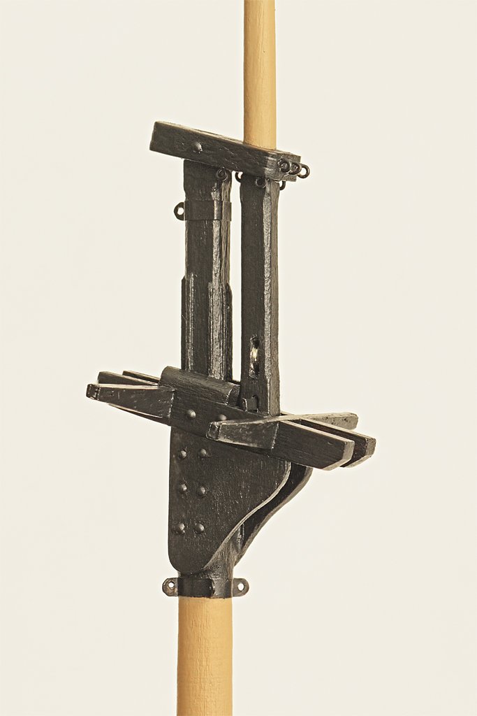
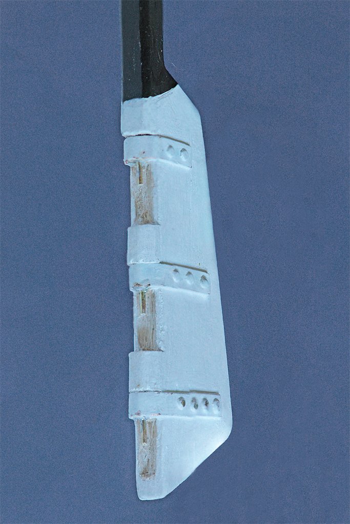
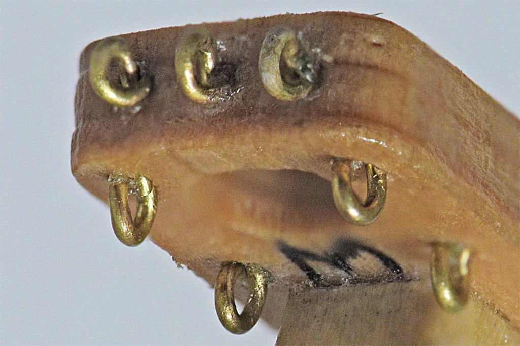
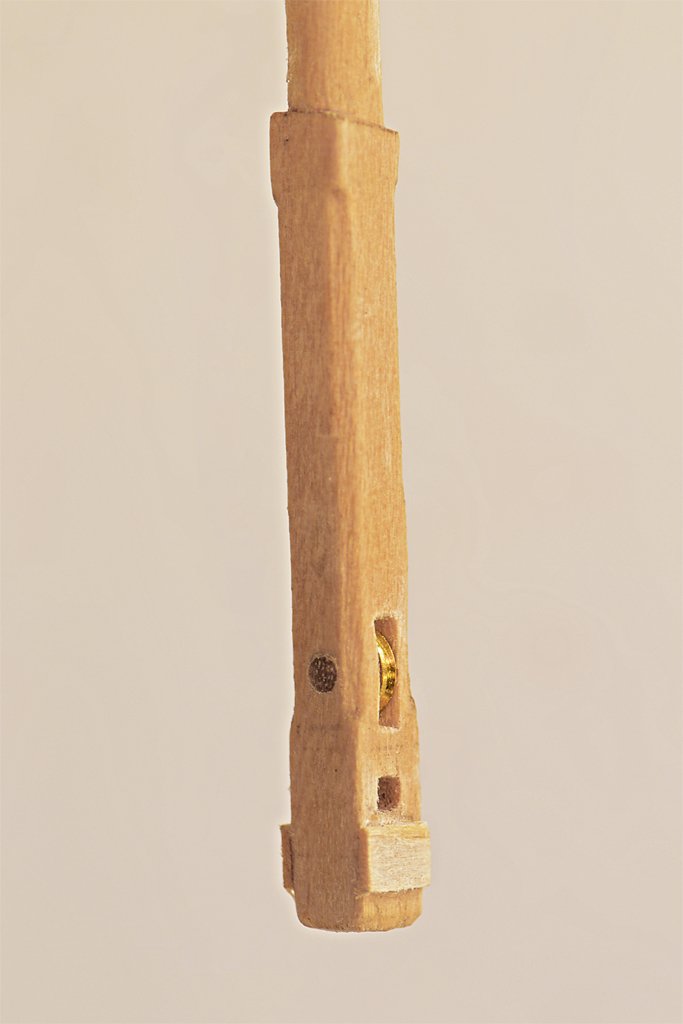
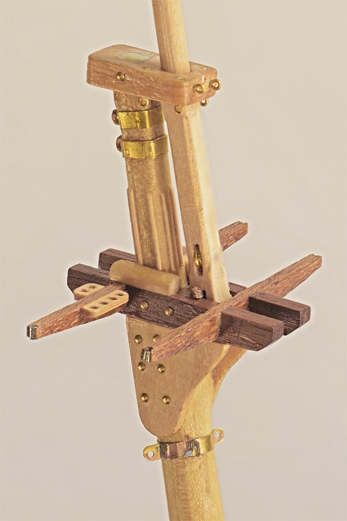
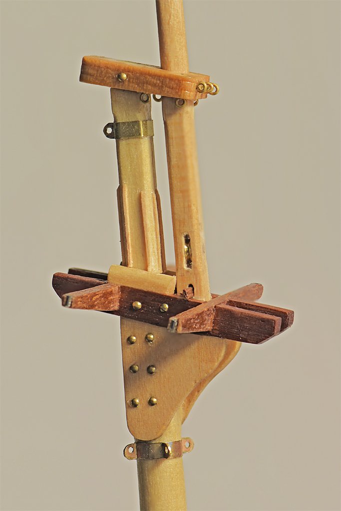
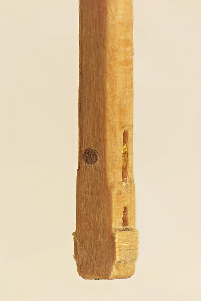
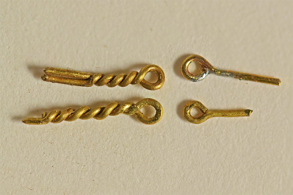
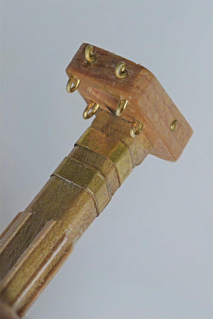
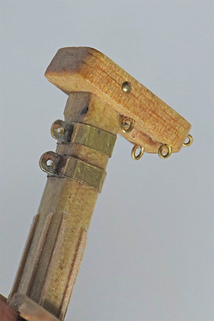
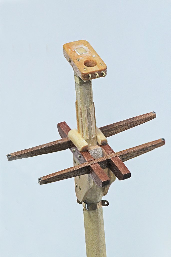
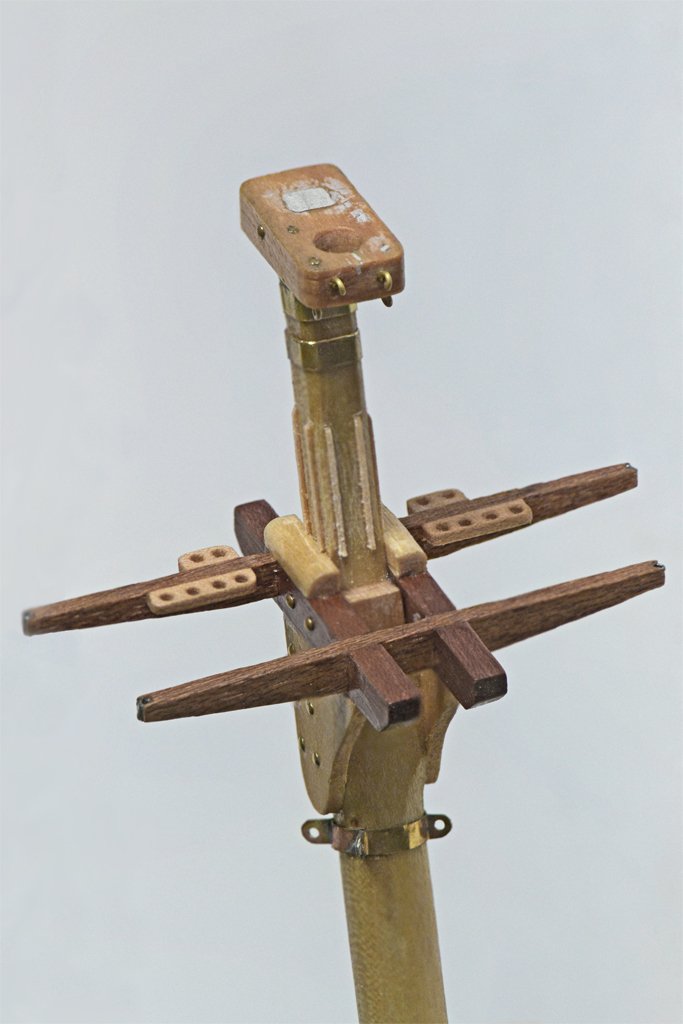
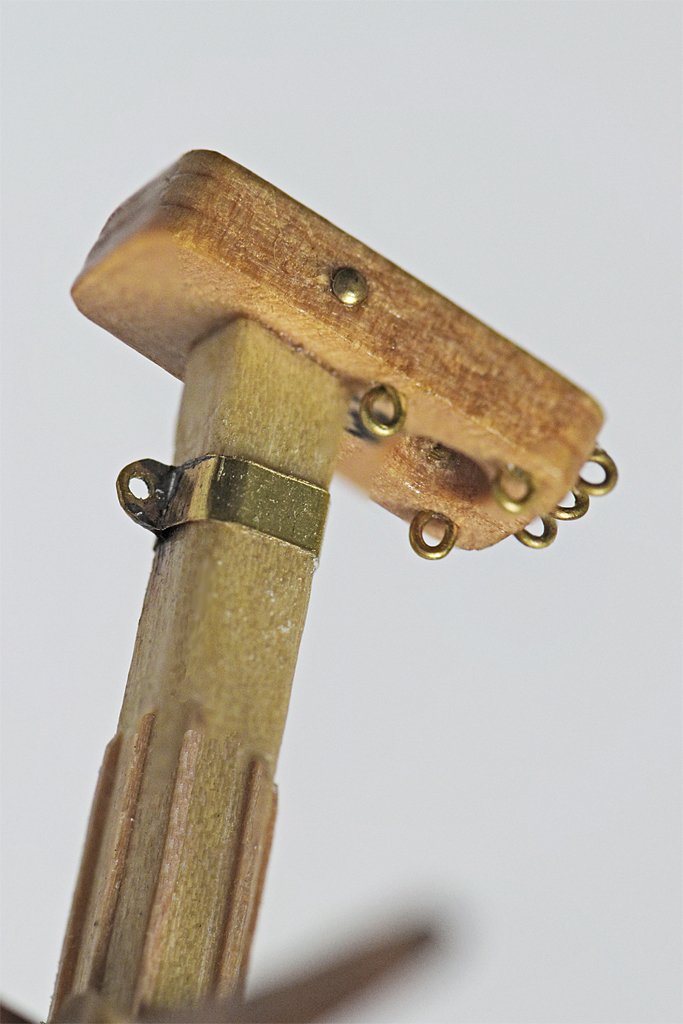
I have been busy with home improvements and a vacation, but finally got around to finishing the mast tops. The mast caps were the same size for both masts, but the square holes were different for the two masts, so I marked them with "M" and "F" so I didn't get them mixed up. Paint will cover this. Marquardt's "Global Schooner" said the caps were bolted to the top of the mast, so I used some 7 mm brass nails to simulate the bolt heads. This ensures the caps are securely attached to the mast top. The main mast cap has three ring bolts on the front. These are for the port and starboard fore topsail yard braces and the main top staysail sheet. The lower forward ring bolts are for the port and starboard fore course yard braces. The after two ring bolts are for the top ropes for raising and lowering the topmast. The brass band with the eye around the mast top is for the main gaff peak halliard. The complete main top shows the bolts that fastened the crosstrees to the mast and the fid that supports the top mast. I set short pieces of hypodermic tubing in the outer ends of the crosstrees for the futtock shrouds to pass through. I suppose I could have just run the lines through notches in the ends of the crosstrees but I worried the wood might split when I tensioned the lines. The mast top has eight battens around the lower part of the mast head. Marquardt said these were often used to prevent chafing of the mast by the stays and shrouds. They are chamfered at the top to make it easier to place the shrouds and stays. Very few models have these pieces but I decided to include them. The fore mast cap has two ringbolts on the forward edge for the port and starboard fore course yard lifts. The lower front ring bolts are for the topping ropes to raise and lower the topmast. The rear pair of ring bolts are for the port and starboard fore course buntlines. The upper brass band with eye is for the main topmast stay. The lower band and eye are for the fore gaff peak halliard. The fore mast top is similar to the main mast top. Not shown is a ring bolt on the aft side set into the mast above the crosstree. This is a fastening point for the lashings used to tighten the main topmast stay. The bottoms of the fore and main topmasts are nearly identical. Small cheeks are attached to the sides of the topmasts to make these narrower masts fit the gap between the trestletrees. The fid holes can be seen, as well as the sheaves for the top ropes. The sheaves were constructed from two small #2 brass flat washers soldered together as described earlier in post #32. I tried a new method of making ring bolts that was described by others on the Forum. Both methods use 0.020" (0,5 mm) 24 American Wire Gauge brass wire. The method I have used for decades is shown on the right. The wire is formed into the ring and the gap is soldered. The new method involved twisting the wire together as shown on the left. I thought this "screw thread" like form would allow glue to fill the hole around the wire and secure the ring bolt in the hole better. However, as the close-up photo on the right shows, the rings are distorted and not flat as they should be. I do not like this! They may be more secure but I think I won't use this method again. The straight wire type shown above can be pulled out if the rigging is tightened too much. In the past I have bent slight kinks in the part that fits into the mounting hole making a tighter fit, and this works OK if you don't over tighten the rigging. The entire topmast assemblies have a coating of shellac to seal the wood grain and cracks between pieces. Now I have to decide what color I am going to paint the mast tops. Most models of American and British ships from the early 1800s have black tops. Black paint was cheap and readily available. By the end of the century mast tops were almost exclusively painted white. Apparently this practice started in the 1830s, but I have found no definitive period description of masthead colors. I prefer white because it shows details better than black.

-
Topsail schooner sail plans and rigging
Dr PR replied to Dr PR's topic in Masting, rigging and sails
I found this image on line that shows what you are talking about a bit better I do not know how they attach the sail to the ring around the mast. It is possible that they have a line attached to the sail that passes through the ring and down to the deck. There is a line visible in this photo but it could be the halliard. When the sail is hauled down the line would come down with it. The line would loop through the ring and both ends would be belayed on deck when the sail was removed. When they rig the sail on deck the line would be attached to the sail, and could be used to help haul the sail aloft. Once aloft this line could be pulled taut to pull the point on the sail down and close to the ring. But that is just a guess. This is another example of the many variations on rigging found with the fore-and-aft rigs.
- 104 replies
-
- 3
-
-
- schooner rigging
- Topsail schooner
- (and 1 more)


