


Dr PR
-
Posts
2,471 -
Joined
-
Last visited
Content Type
Profiles
Forums
Gallery
Events
Everything posted by Dr PR
-
 Valeriy is obviously a very experienced model maker. In addition to the clean crisp lines I am impressed that he really understands the order that the assembly needs to go together. And he doesn't forget to clean off the dust before he takes his photos!
 -
I have searched through the forum for information about the color or finish on masts, mast tops and bowsprits and there are only a few posts. I thought I would create a separate topic. I am building a model of an early 1800s American Revenue Service schooner, but I am interested in painting practices on other ship types, eras and nationalities as well. I have found no historical records of the colors or finishes on revenue cutter masts. Rather, in early American vessels, including the early US Navy, there seems to be no standard color scheme. Many ship owners and captains followed British practice, but others didn't. Sometime after about 1830 it seems the US Navy did adopt a standard color scheme. Were masts and bowsprits painted or just left the natural wood color? I have seen both on modern models. I have read that some vessels had "natural wood color" masts, but the masts were greased where the mast hoops moved, and were darker as a result in these parts. If painted, what colors were common? Was the entire mast painted or only parts of it? How did this vary over time? What color was common for the tops (doubling and crosstrees)? I have seen black on some models and white on others. What periods were these colors common? Another interesting discussion was about the color of mast hoops. I read that the hoops were a different color from the masts in the British (and other) navy up to Trafalgar. Then Nelson ordered that the mast hoops be repainted to the same color as the masts so the British ships could be distinguished easily from the opposing ships. Unfortunately, the posts discussion this didn't say what the colors were for the masts and hoops before Trafalgar! All comments and discussion are welcome!
-
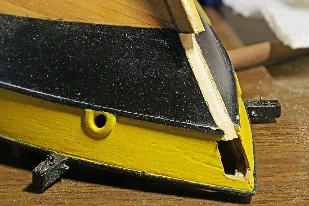
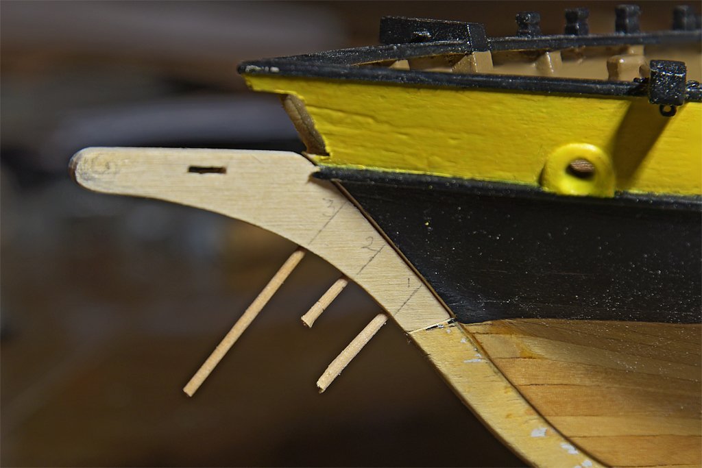
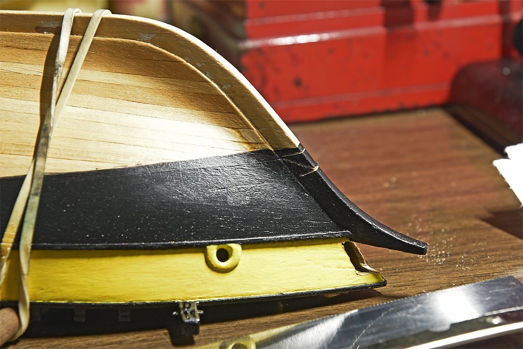
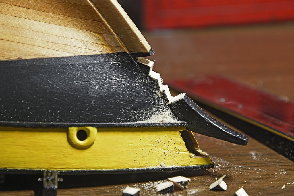
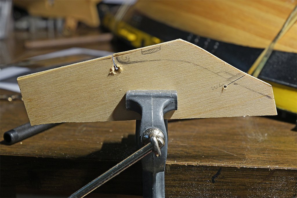
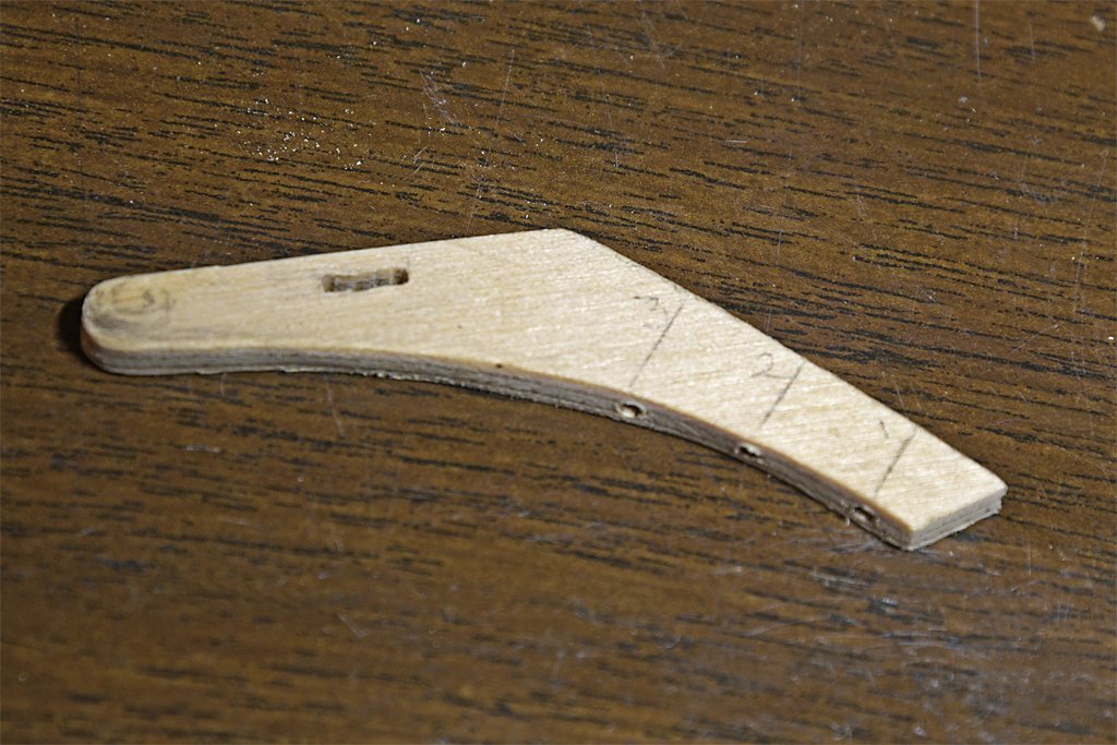
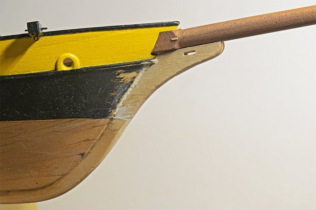
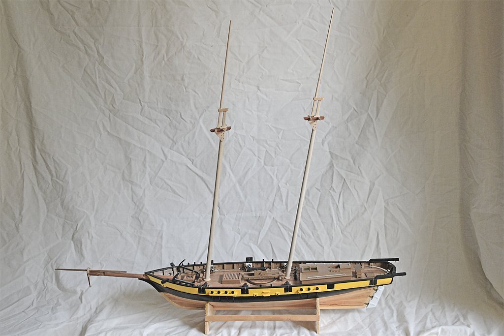
I performed surgery on the bow of the ship. The "knee" that projected under the bowsprit wasn't long enough or thick enough for the gammoning that was needed. Between the 1980s when this project was started and through several moves about 1/2 inch (12.5 mm) was broken off the tip. I decided it was about time to replace the knee. The amputation began with a series of saw cuts to remove material. I was a bit anxious about working on this because the plywood the stem was made of was quite old and the layers might separate. However the wood was soft and cut easily. The operation was successful and the cut area cleaned up nicely. The next step was to fashion the prosthesis out of a (relatively) new piece of plywood. I selected a piece from my scrap box and shaped one edge to fit the place on the hull. After that I used a coping saw to rough out the part. Then I used files to refine the edges to fit the hull and the bowsprit. Finally I finished shaping the part so the curves matched the curves of the hull. After cutting the hole for the gammoning rope I drilled three 1/16 inch (1.5 mm) holes through the part for wooden pegs to give strength to the joint when it was glued to the hull. I made the pegs from bamboo cooking skewers. The new knee served as the template for drilling holes in the hull for the pegs. The photo on the left shows the part temporarily pegged in place. On the right is the finished part glued in place, with some putty to fill in a few chips and create a filet where the planking met the stem. The repair is very sturdy. It looked as if the knee might be a bit too long so I took measurements from a dozen drawings in Marquardt's "The Global Schooner" and averaged the results. The length of the knee was compared with the bowsprit length from the hull planking to the bowsprit cap. The length of the knee varied from 0.17 to 0.39 times the length of the bowsprit outside the hull, with an average of 0.25. The new piece was a bit longer than average but I trimmed it back to 1/4 the length of the bowsprit outside the hull. Now I just need to seal the wood and paint the bow.
- 421 replies
-
- 10
-

-
Off and running with the schooner rigged pond yacht
Dr PR replied to Elmina's topic in Masting, rigging and sails
Fore-and-aft rigged schooners often did not have rat lines, and the spacing between your shrouds makes it unlikely that the boat had them. Access to the upper mast was either by bosun's chair as Kieth said, or just by climbing the mast rings when the sails were set. And "bosun's chair" is a rather loosely defined term. Often it is just a rope sling that you sit on while someone hoists you up the mast. -
I have been using the free Chitubox and I am satisfied within how it works. Their tech support is pretty amazing, often responding within a few minutes to my email questions! 1. You can create custom settings for different resins and save them for future reference. 2. You can add settings for any printer - if you know them. For my Anycubic Mono I just started their Photon Workshop slicer program (not nearly as good as Chitubox) and copied the settings from it. 3. Chitubox sometimes doesn't add enough default supports and the print fails, leaving the part stuck to the FEP film. I have been manually placing supports with mostly good results. Most of the failures I am seeing are always due to not enough supports near edges and corners. If it isn't supported a surface will flex during printing and come out warped. Another related problem is supports that are too narrow at the contact point with the print part - the support doesn't connect to the printed part and is worthless. 4. Chitubox offers many options for designing individual supports, including the base shape and size, support shape and width, support end diameter, shape and depth of penetration into the surface. The only thing that doesn't seem to work correctly is cross links between supports. For me these are a nuisance, but turning them off in the settings doesn't prevent the program from adding them anyway. These can make it very difficult to remove supports from fine details. **** On another topic, I have using denatured alcohol (95% ethanol and 5% methanol). This was recommended by Anycubic for cleaning their Basic Grey resin. It is sold in gallon cans for about $18 the last time I looked - look for it in the paint stripper and wood finish products. It has always been cheaper that 95% isopropanol (isopropyl alcohol), primarily because it is available in gallon quantities. **** And now a question: I read in someone's post that they used hot water or a heat gun to soften warped pieces and then bend them back into shape. Has anyone tried this? Do you heat the part before curing or after? The single greatest frustration I have found with 3D printing is that thin details like hand rails are often distorted by the forces of separating the print from the FEP and then pressures from resin flow as the part returns to print the next layer. These parts are always bent between the supports, and often come out "fat" in between supports. So far this problem has made 3D printing useless for many of the things I have tried to make. If I can reshape the warped railings and pipes after printing there are a lot more things I could use 3D printing for.
-
Off and running with the schooner rigged pond yacht
Dr PR replied to Elmina's topic in Masting, rigging and sails
Belaying plans (where the rigging tied off on deck) are rarely found for ships because everyone knew how to do it and didn't need a plan. The fore-and-aft schooner rig was pretty simple (compared to a square rigged ship). Normally there would be pin rails along the bulwarks along the sides of the hull (but your model doesn't have bulwarks) and the fife rails at the base of the masts. Lines could also belay to ring bolts in the deck at the base of the masts and along bulwarks and cleats near the bottom of the masts and on the bulwarks. The general rules for belaying the running rigging were: 1. Lines from lower on the mast would go to the more forward belaying points and lines from higher on the mast would go to belaying points more aft on the rails. This makes sense because masts often had rakes leaning aft so the origins for lines higher on the mast would be more aft than those lower down. A few vessels had forward raking fore masts so the rule would be reversed in this case. 2. Lines originating on or close to the masts led down to the base of the mast, and lines originating nearer the ends of spars (square rigged) would lead down to pin rails, cleats or ring bolts on or near the bulwarks. On some vessels lines from the higher parts on the masts were belayed to points on the bulwarks or along the sides of the deck. 3. Lines must run free without touching other lines (or anything else). If ropes rubbed against something they would chafe and this could lead to the line parting. At sea the ship pitched and rolled and everything aloft was in motion. Even in port the winds and tides caused the ship to move. If a line rubbed against anything else it would cause wear on the line and whatever it touched - even a sail. Where lines must touch something else they were wrapped in chafing gear (wraps of canvas and/or rope) that was supposed to take the wear. The idea behind these rules was to prevent lines from crossing and getting tangled with one another. Since there is no original belaying plan for your model you can rig it just about any way you want. Keep these rules in mind and you can't go wrong in rigging the model. -
Howard Chapelle would approve! Would this be the hoy Delay mentioned in Shakespeare's "Comedy of Errors" Act 4, Scene 3?
-
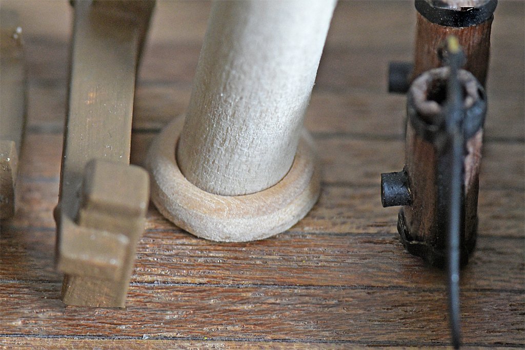
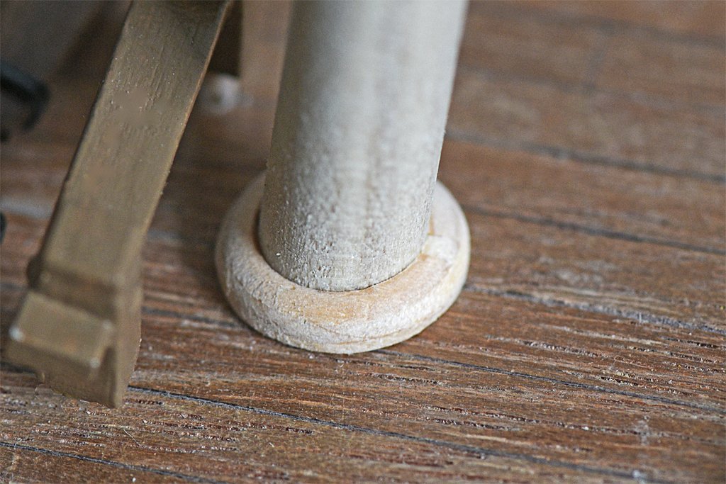
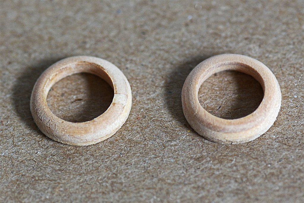
I enlarged the mounting holes in the deck and installed the masts (temporarily). I made the mast coats to fit around the bases of the masts. These things were quite a challenge! They are 0.5 inch (12.7 mm) diameter. I figured if I tried to make them from an ordinary sheet of wood they would break apart while I was shaping them. So I decided to use 1/8 inch (3.2mm) plywood, hoping the cross grains would hold them together. I picked a piece out of my scrap box, and I have no idea how old it was. But in hindsight it could have been left over from a kit from the 1960s. That stuff wasn't very good plywood to begin with, and the glue they used to hold the laminations together was pretty poor. I think the wood was holding the glue together. Again and again pieces of the outer layers chipped off and I had to recover them and glue (Duco Cement) them back on. In some cases the pieces went to never never land and I had to strip a bit of a layer from scrap plywood, shape it and glue it in place. You can see one of these patches in the left hand part. But as you can see I eventually got the parts shaped suitably. I will seal them and paint with the same brown as the bulwarks.

-
Problem creating new posts
Dr PR replied to Dr PR's topic in Using the MSW forum - **NO MODELING CONTENT IN THIS SUB-FORUM**
I can't delete all cookies (too many bank account logins, IRS and other government links, plus forums and other sites that I use regularly) but I just went through the very long list and deleted most of them. I just made a test post on the Albatros thread and it worked. It was very strange that the problem was only on that single thread. Thanks. -
Recently I have been having a problem creating new additions to my Albatros thread. When I click in the "Reply" box nothing I type appears there. Instead the "Drag files here to attach ..." is all I see. I have tried saving the new entry and opening it again, but all I see is the "drag files ..." box. The only way I have been able to start a new entry is to load some pictures and select one. After this I can add text after the photo, but there seems to be no way to go to the start of the post. So I save the new post, open it again, add text after the picture and then delete the picture. This puts my text at the start of the post. After this I can add more text and pictures. This started happening about a week ago and has happened several times now. I do not have a problem adding new posts in other threads on the Forum.
-
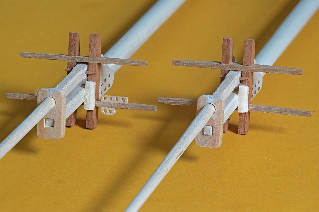
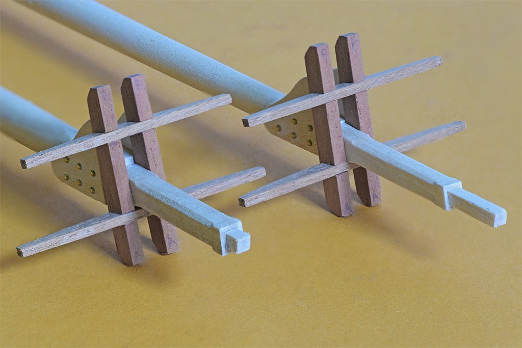
Here is a bit more progress. I have made all of the wooden parts of the mast tops and trimmed everything to fit. All parts need sealer and sanding. Above the cheeks on the mast head is a spacer block that is a rest for the topmast heel. The crosstree assembly has the bolsters and guides for topmast rigging. The topmast stays will be rigged to the ends of the crosstrees. The topmast lower part has been shaped and has the fid hole - the fid is the small piece of wood. The mast cap has a snug fit on the top of the lower mast tenon and a loose fit for the topmast. The parts of the fore top are shown on the left. The main mast (right) doesn't have a square topsail so the rigging is much simpler and the guides for the rigging aren't needed. The topmast slips into the crosstree assembly from below and then passes through the hole in the top. After the mast is full up the fid is inserted to hold it in place. This is how the real topmasts worked. I haven't cut the slot for the sheave for the uphaul rope. Also missing are bunch of ring bolts for all the stays and tackles that attached to the tops. I should have created a 3D CAD model before moving on to cutting wood. There are a couple of less than perfect parts. The bolsters are too beefy. This is basically because the trestletrees are probably a bit too wide, but they are still within the extreme ranges of the calculations mentioned a few posts above. I think I will file the bolsters to remove some material from the tops. The other problem is the position of the guides for the topmast rigging on the fore mast. These allow routing the topsail running rigging clear of other rigging to ensure the lines do not foul other rigging. The guides are very close to the trestletrees, and the lower mast shrouds have to pass between them and the trestletrees. Fortunately there aren't a lot of shrouds (three per side on the fore mast plus the fore tackle/burtoning tackle. The clearances between the shrouds and running rigging looked good on the 2D drawings. I may have to move the guides, and that could be tricky. I was surprised that I could make the tiny pieces without them breaking apart when I drilled the holes. The holes are 0.057 inch (1.4 mm) diameter on 0.1 inch (2.54 mm) spacing.
-
Dave, I am kit bashing a 1980s topsail schooner. The kit plans did not include a lot of the rigging on an actual ship - it was a simplified rigging plan. After I started doing research on these ships I realized I would not have enough blocks for the additional rigging. In addition, the kit supplied thread was pretty fuzzy and there were only two or three sizes. Neither the "ropes" nor blocks were to scale. When I started looking at the way rope sizes were calculated I learned that block sizes are determined by rope sizes. All this led me to decide to replace all the ropes and blocks. This wasn't so much to make a "correct" model because what I am building if a fictitious ship anyway. But I wanted the experience of creating a true to scale rigging on the model. I bought rope and blocks from Syren and the cost came out to about $270. That's quite a bit more than I paid for the kit! But Chuck's products are very nice. Keep this cost in mind. The topsail schooner has square sails on the fore mast only, and there are only two masts. The Rattlesnake has a LOT more rigging. I haven't tried to figure that out yet for the Rattlesnake kit I have, but I'll bet there are 5 to 10 times as many blocks as the simple schooner rig, and a lot more rope. You can use much of the material in the kit even if it isn't the best quality. But some pieces are just stock items the company had on the shelf and are either out of scale or just inappropriate for the vessel and period you are modeling. So for these parts you might want to make substitutions. But in the end it all boils down to asking yourself what you want to build.
-
For what it is worth, a wooden minesweeper I served on had an inner layer of diagonal planking with an outer layer of traditional longitudinal planking. It produced a strong hull without any (magnetic) metal parts.
- 454 replies
-
- 2
-
-
- Union Steamship Company
- Stepcraft 840
- (and 3 more)
-
After all that fuss I made the tops according to my original plan with a few minor tweaks to fit the masts. Since the top masts are the same on both fore and main masts the tops are also the same. There are few additions I will make before finishing them - bolsters and such. The wood is pretty grainy so I need to seal with sanding sealer or maybe shellac. The tops will be painted so the different colors of the wood won't matter.
-
I decided to take all of the conflicting dimensions for trestletrees and crosstrees and average them to get values for my model. That is how I determined the mast dimensions that I am using. Here are all of the "rules": Trestletree Dimensions Cock: Length = 5 x diameter of mast at hounds Height = ½ diameter of mast at hounds Width = 1/3 diameter of mast at hounds Trestletrees are bolted through the mast with 2 bolts and are centered on the lower mast. Hedderwick: Size = 7/8 diameter of mast at partners (not less than ¾) Length = 5 ½ to 6 times diameter of mast OR ½ breadth of top Height = 5/6 diameter of mast at hounds Width = 3/7 of the trestletree height Kipling: Length = top length fore and aft = 2/3 to ½ top width Height = ½ diameter of mast at partners Width = ½ trestletree height Top width = 1/2 molded beam Chapman: Height (inches) = topmast length (feet)/4 – ½ inch Width = 5/7 trestletree height Mondfeld: Length = 0.3 to 0.35 beam Height = 0.08 x trestletree length Width = 0.9 x trestletree height Lees: Length = 3 ¾ inch per yard of topmast length (0.104 times topmast length) Height = 1 inch per foot length (1/12 length or 0.083 times length)) Width = 2/3 trestletree height Lower tops width (transverse) = 1/3 length of topmast. Length (longitudinal) 3/4 top width. Marquardt: Length = 3 ½ inch for every yard of topmast length (0.097 times topmast length) Height = 1 1/8 inch for every foot trestletree length (0.094 times length) Width = 2/3 trestletree height Crosstree DImensions Cock: Length = (11/12 x beam)/2 Height = ½ trestletree height/depth Width = same as trestletree breadth/width Hedderwick: Length = breadth of top = 5/9 beam Height = 5/6 trestletree height Width = 3/7 crosstree height Kipling: Length = width of top = ½ molded beam Height = same as trestletree height = ½ diameter of mast at partners Width = 2/3 crosstree height Chapman: Height = 3/7 trestletree height Width = ¾ crosstree height Anderson: (for circular top trestletree length = crosstree length) Length= masthead length or a little more Height = 1/13 trestletree length Width = 7/8 or 9/10 trestletree height He cites other references that say the length should be 1/3 the beam, ranging from 0.36 to 0.25 times the beam for smaller ships Lees: Length = 1 2/3 times length of trestletree Height = 7/8 x height of trestletree Width = same as trestletree (2/3 trestletree height) Marquardt: Length = 1 1/3 trestletree length Height = 7/8 trestletree height Width = 1 ¼ trestletree width References: Anderson, R. C., “Seventeenth Century Rigging,” 1955 Chapman, Frederick, “Treatis of Shipbuilding,” 1820 (Archetectura Navalis Mercatoria) Cock, John, “A Treatise on Mast Making,” 1840 Hedderwick, Peter, “A Treatise on Marine Architecture,” 1830 Kipling, Robert, “Rudimentary Treatise on Masting, Mastmaking and Rigging,” 1864 Lees, James, “The Masting and Rigging of English Ships of War,”1979 Marquardt, Karl, “The Global Schooner,” 2003 Mondfeld, Wolfram, “Historic Ship Models,” 1989 I think the large differences for some of the results are caused by some of the authors giving rules for tops with platforms, where the trestletrees will be much longer than for tops without platforms. Other than those numbers all of the calculations gave values that were pretty close to each other. After averaging the results from all of these calculations - excluding those results that were 2X or more than the other values - I found that the dimensions in my original drawings fell within the range of values from the calculations. So I will go with what I already came up with.
-
USS MAINE by steven. R - sheet metal
Dr PR replied to steven. R's topic in - Build logs for subjects built 1901 - Present Day
The USS Maine story is an interesting one. It wasn't the US government that blew it up into an excuse for a war. It was the Hurst newspaper chain - perhaps the best example of "yellow journalism." It was a tragedy, and subsequent studies have failed to give a definitive cause for the explosion, but some possible causes have been determined. But the Hurst chain blew the story up into tremendous hyperbole to sell more newspapers. They blamed the Spanish and editorialized that the US should go to war. Not much (any?) of what they said was true, but they got their war, sold a lot of papers and got rich. Unfortunately, our current trends in "news" reporting isn't much different from Hurst's yellow journalism. The goal is to make money, and news reporting has become infotainment, with different sources slanting the stories to appeal to some particular bunch of suckers. Just a bunch of talking heads reading the appropriate propaganda. George Orwell's fantasy has come true. Truth is lies. Ignorance is strength. -
That formula is very useful - I hadn't tried to calculate it myself. arctan(layer height/pixel width) Use the same units (inch, millimeter, whatever) for both layer height and pixel width. The videos assume that most people print at a 0.05 mm slice thickness, and that is common. But you can improve surface smoothness by using thinner slices. My Photon Mono will print 0.01 mm slices and this makes much smoother horizontal surfaces. But As I noted in my earlier post, layer/slice thickness has no effect for angles greater than 45 degrees - for these surfaces pixel size is the limit. Chitubox allows several antialiasing settings (Anti-aliasing Level, Grey Level and Image Blur Pixel). These settings cause the "jaggies: to be filled in partially, significantly reducing the effect. With the proper print angle and adequate antialiasing settings you can get surfaces that are so smooth that you need a magnifier to see any roughness, and then it may only be visible as a slight light pattern on the surface.
-
A good way to clean up solder joints and remove excess solder is to use a wire brush in a motor tool. Steel brushes remove solder quickly. Brass wire brushes work a little slower, but you have to be careful or you may remove too much. The parts come out polished nicely.
-
The "ideal" angle of 45 degrees is for prints with the vertical step (slice) thickness equal to the horizontal pixel size. This will generate the smallest "jaggies" but also the most of them. Steeper vertical angles produce jaggies that are the pixel size but a lot fewer of them. At angles less than 45 degrees the jaggies size is dependent upon slice thickness and the number is dependent upon the pixels in the slice. I posted some drawings and photos in post #173 in this thread that illustrate these effects and discussed how to minimize them.
-
I would definitely run all the wiring internally. This protects it from being damaged, as might happen with the external wires. Just run dummy wires externally, and if one gets damaged it will be MUCH easier to replace than a wire that is part of the electrical circuit! There are two ways to dim the LEDs. One is to pick the right resistor value to get the brightness you want with the voltage you are using. Larger resistor values = lower current = lower light output. The other is to change the voltage output of the power supply. You can do this by placing one power resistor (large enough to handle the total current flowing in the circuit (power in Watts = current times voltage). Do not forget to take into account the heat all of these LEDs and their power supply will generate. Just assume that all the power will come out as thermal energy inside your model. Some power is actually lost as light, but assuming all will be heat gives you a safety margin. You may want to have a small ventilation fan to force airflow through the model.
- 454 replies
-
- 2
-
-
- Union Steamship Company
- Stepcraft 840
- (and 3 more)
-
There are a couple of issues there that I have been experimenting with. 1. Any large surface parallel to the print plate/FEP will come out lumpy, no matter how many supports you have. The force needed to pull the print surface away from the FEP will cause the print to pull away from the outside edges where the support density is lowest. This allows the printed surface to bend, especially for the first few very thin slices after the supports have printed. Another problem is the forces generated when the print rises from the resin vat (to allow more resin to flow over the FEP) and then descends back into the resin vat. The pressure generated when the resin is squeezed out from between the print object and the FEP film can cause the thin printed surface to bulge up between the supports. So the newly printed surface is in the middle of a tug of war between the separation forces when the print lifts and the pressure forces when the print descends again. The result is a warped surface for the first few slices and then the rest build up on this surface. You can reduce both of these forces by setting (Chitubox/Settings/Print tab) a slower Lift Speed and Retract Speed. This may significantly increase the overall print time, bit may be what is necessary to get a good print. 2. Print times also affect how these thin layers and small diameter objects come out. The resin is pretty much transparent to UV light. This means that as very thin objects are printed horizontally some light penetrated the current slice and exposes resin on top of it. Sole light is also scattered in the resin causing extra resin to be cured along the edges of the part. Thin narrow parts may flex as described above, displacing the parts between supports slightly. New layers are printed in the correct position, causing the part to be fatter in the middle between supports. Reducing the exposure time reduces the amount of this excess resin exposure. 3. A solution to these problems is to place the part at an angle to the print surface/FEP film. In theory a 45 degree angle should give the best surfaces, but this may not work with long parts that would extend out of the print area. But in practice a 15 degree angle from vertical works pretty well. 4. Another solution is to position the part so it has the smallest possible surface area in contact with the FEP at each slice. Hollowing the part may be necessary to accomplish this, The Chitubox Hollow function does this very nicely, and adds internal supports necessary to support the print. Be sure to use the "Dig Hole" function to make a drain port so resin can drain out of the interior of hollow parts. Adding the drain port on the surface nearest the print platform will also reduce suction from resin in the the hollowed part while the part is lifting from the FEP. 5. Finally, what is the room temperature where your printer is located? The curing of resin is a chemical process. It is triggered by the UV light, but the rate at which it cures is very temperature dependent. If it is too cold the resin will not cure quickly and things may come out too thin. Also, the resin flows more slowly when cold, and this can increase the pressures as the part lifts from the FEP and descends again. On the other hand, if the resin is too warm it will cure extra fast, and this can exaggerate the over curing from UV light penetrating the excision layers and scattering in the resin. Check what the manufacturer recommends for the printing temperature.
-
Cleaning old models does not involve anything exotic, but does take some work and a lot of care. If you want tips on cleaning this model I suggest you start a new thread asking how to clean an old model. There are some very experienced model restorers on this forum.
-
Several people have recommended shellac as a "binder" for loose rope ends, served lines, etc. It shouldn't react chemically with the polymer thread, and soaks into the thread/rope and dries as a hard colorless film.
-
Valeriy, Good to hear from you again! Very nice work! Your model is beautiful. I only wish I could see it in person.


