HOLIDAY DONATION DRIVE - SUPPORT MSW - DO YOUR PART TO KEEP THIS GREAT FORUM GOING! (Only 13 donations so far - C'mon guys!)
×


Dr PR
-
Posts
2,401 -
Joined
-
Last visited
Content Type
Profiles
Forums
Gallery
Events
Everything posted by Dr PR
-
 I decided to take all of the conflicting dimensions for trestletrees and crosstrees and average them to get values for my model. That is how I determined the mast dimensions that I am using. Here are all of the "rules": Trestletree Dimensions Cock: Length = 5 x diameter of mast at hounds Height = ½ diameter of mast at hounds Width = 1/3 diameter of mast at hounds Trestletrees are bolted through the mast with 2 bolts and are centered on the lower mast. Hedderwick: Size = 7/8 diameter of mast at partners (not less than ¾) Length = 5 ½ to 6 times diameter of mast OR ½ breadth of top Height = 5/6 diameter of mast at hounds Width = 3/7 of the trestletree height Kipling: Length = top length fore and aft = 2/3 to ½ top width Height = ½ diameter of mast at partners Width = ½ trestletree height Top width = 1/2 molded beam Chapman: Height (inches) = topmast length (feet)/4 – ½ inch Width = 5/7 trestletree height Mondfeld: Length = 0.3 to 0.35 beam Height = 0.08 x trestletree length Width = 0.9 x trestletree height Lees: Length = 3 ¾ inch per yard of topmast length (0.104 times topmast length) Height = 1 inch per foot length (1/12 length or 0.083 times length)) Width = 2/3 trestletree height Lower tops width (transverse) = 1/3 length of topmast. Length (longitudinal) 3/4 top width. Marquardt: Length = 3 ½ inch for every yard of topmast length (0.097 times topmast length) Height = 1 1/8 inch for every foot trestletree length (0.094 times length) Width = 2/3 trestletree height Crosstree DImensions Cock: Length = (11/12 x beam)/2 Height = ½ trestletree height/depth Width = same as trestletree breadth/width Hedderwick: Length = breadth of top = 5/9 beam Height = 5/6 trestletree height Width = 3/7 crosstree height Kipling: Length = width of top = ½ molded beam Height = same as trestletree height = ½ diameter of mast at partners Width = 2/3 crosstree height Chapman: Height = 3/7 trestletree height Width = ¾ crosstree height Anderson: (for circular top trestletree length = crosstree length) Length= masthead length or a little more Height = 1/13 trestletree length Width = 7/8 or 9/10 trestletree height He cites other references that say the length should be 1/3 the beam, ranging from 0.36 to 0.25 times the beam for smaller ships Lees: Length = 1 2/3 times length of trestletree Height = 7/8 x height of trestletree Width = same as trestletree (2/3 trestletree height) Marquardt: Length = 1 1/3 trestletree length Height = 7/8 trestletree height Width = 1 ¼ trestletree width References: Anderson, R. C., “Seventeenth Century Rigging,” 1955 Chapman, Frederick, “Treatis of Shipbuilding,” 1820 (Archetectura Navalis Mercatoria) Cock, John, “A Treatise on Mast Making,” 1840 Hedderwick, Peter, “A Treatise on Marine Architecture,” 1830 Kipling, Robert, “Rudimentary Treatise on Masting, Mastmaking and Rigging,” 1864 Lees, James, “The Masting and Rigging of English Ships of War,”1979 Marquardt, Karl, “The Global Schooner,” 2003 Mondfeld, Wolfram, “Historic Ship Models,” 1989 I think the large differences for some of the results are caused by some of the authors giving rules for tops with platforms, where the trestletrees will be much longer than for tops without platforms. Other than those numbers all of the calculations gave values that were pretty close to each other. After averaging the results from all of these calculations - excluding those results that were 2X or more than the other values - I found that the dimensions in my original drawings fell within the range of values from the calculations. So I will go with what I already came up with.
 -
USS MAINE by steven. R - sheet metal
Dr PR replied to steven. R's topic in - Build logs for subjects built 1901 - Present Day
The USS Maine story is an interesting one. It wasn't the US government that blew it up into an excuse for a war. It was the Hurst newspaper chain - perhaps the best example of "yellow journalism." It was a tragedy, and subsequent studies have failed to give a definitive cause for the explosion, but some possible causes have been determined. But the Hurst chain blew the story up into tremendous hyperbole to sell more newspapers. They blamed the Spanish and editorialized that the US should go to war. Not much (any?) of what they said was true, but they got their war, sold a lot of papers and got rich. Unfortunately, our current trends in "news" reporting isn't much different from Hurst's yellow journalism. The goal is to make money, and news reporting has become infotainment, with different sources slanting the stories to appeal to some particular bunch of suckers. Just a bunch of talking heads reading the appropriate propaganda. George Orwell's fantasy has come true. Truth is lies. Ignorance is strength. -
That formula is very useful - I hadn't tried to calculate it myself. arctan(layer height/pixel width) Use the same units (inch, millimeter, whatever) for both layer height and pixel width. The videos assume that most people print at a 0.05 mm slice thickness, and that is common. But you can improve surface smoothness by using thinner slices. My Photon Mono will print 0.01 mm slices and this makes much smoother horizontal surfaces. But As I noted in my earlier post, layer/slice thickness has no effect for angles greater than 45 degrees - for these surfaces pixel size is the limit. Chitubox allows several antialiasing settings (Anti-aliasing Level, Grey Level and Image Blur Pixel). These settings cause the "jaggies: to be filled in partially, significantly reducing the effect. With the proper print angle and adequate antialiasing settings you can get surfaces that are so smooth that you need a magnifier to see any roughness, and then it may only be visible as a slight light pattern on the surface.
-
A good way to clean up solder joints and remove excess solder is to use a wire brush in a motor tool. Steel brushes remove solder quickly. Brass wire brushes work a little slower, but you have to be careful or you may remove too much. The parts come out polished nicely.
-
The "ideal" angle of 45 degrees is for prints with the vertical step (slice) thickness equal to the horizontal pixel size. This will generate the smallest "jaggies" but also the most of them. Steeper vertical angles produce jaggies that are the pixel size but a lot fewer of them. At angles less than 45 degrees the jaggies size is dependent upon slice thickness and the number is dependent upon the pixels in the slice. I posted some drawings and photos in post #173 in this thread that illustrate these effects and discussed how to minimize them.
-
I would definitely run all the wiring internally. This protects it from being damaged, as might happen with the external wires. Just run dummy wires externally, and if one gets damaged it will be MUCH easier to replace than a wire that is part of the electrical circuit! There are two ways to dim the LEDs. One is to pick the right resistor value to get the brightness you want with the voltage you are using. Larger resistor values = lower current = lower light output. The other is to change the voltage output of the power supply. You can do this by placing one power resistor (large enough to handle the total current flowing in the circuit (power in Watts = current times voltage). Do not forget to take into account the heat all of these LEDs and their power supply will generate. Just assume that all the power will come out as thermal energy inside your model. Some power is actually lost as light, but assuming all will be heat gives you a safety margin. You may want to have a small ventilation fan to force airflow through the model.
- 454 replies
-
- 2
-

-
- Union Steamship Company
- Stepcraft 840
- (and 3 more)
-
There are a couple of issues there that I have been experimenting with. 1. Any large surface parallel to the print plate/FEP will come out lumpy, no matter how many supports you have. The force needed to pull the print surface away from the FEP will cause the print to pull away from the outside edges where the support density is lowest. This allows the printed surface to bend, especially for the first few very thin slices after the supports have printed. Another problem is the forces generated when the print rises from the resin vat (to allow more resin to flow over the FEP) and then descends back into the resin vat. The pressure generated when the resin is squeezed out from between the print object and the FEP film can cause the thin printed surface to bulge up between the supports. So the newly printed surface is in the middle of a tug of war between the separation forces when the print lifts and the pressure forces when the print descends again. The result is a warped surface for the first few slices and then the rest build up on this surface. You can reduce both of these forces by setting (Chitubox/Settings/Print tab) a slower Lift Speed and Retract Speed. This may significantly increase the overall print time, bit may be what is necessary to get a good print. 2. Print times also affect how these thin layers and small diameter objects come out. The resin is pretty much transparent to UV light. This means that as very thin objects are printed horizontally some light penetrated the current slice and exposes resin on top of it. Sole light is also scattered in the resin causing extra resin to be cured along the edges of the part. Thin narrow parts may flex as described above, displacing the parts between supports slightly. New layers are printed in the correct position, causing the part to be fatter in the middle between supports. Reducing the exposure time reduces the amount of this excess resin exposure. 3. A solution to these problems is to place the part at an angle to the print surface/FEP film. In theory a 45 degree angle should give the best surfaces, but this may not work with long parts that would extend out of the print area. But in practice a 15 degree angle from vertical works pretty well. 4. Another solution is to position the part so it has the smallest possible surface area in contact with the FEP at each slice. Hollowing the part may be necessary to accomplish this, The Chitubox Hollow function does this very nicely, and adds internal supports necessary to support the print. Be sure to use the "Dig Hole" function to make a drain port so resin can drain out of the interior of hollow parts. Adding the drain port on the surface nearest the print platform will also reduce suction from resin in the the hollowed part while the part is lifting from the FEP. 5. Finally, what is the room temperature where your printer is located? The curing of resin is a chemical process. It is triggered by the UV light, but the rate at which it cures is very temperature dependent. If it is too cold the resin will not cure quickly and things may come out too thin. Also, the resin flows more slowly when cold, and this can increase the pressures as the part lifts from the FEP and descends again. On the other hand, if the resin is too warm it will cure extra fast, and this can exaggerate the over curing from UV light penetrating the excision layers and scattering in the resin. Check what the manufacturer recommends for the printing temperature.
-
Cleaning old models does not involve anything exotic, but does take some work and a lot of care. If you want tips on cleaning this model I suggest you start a new thread asking how to clean an old model. There are some very experienced model restorers on this forum.
-
Several people have recommended shellac as a "binder" for loose rope ends, served lines, etc. It shouldn't react chemically with the polymer thread, and soaks into the thread/rope and dries as a hard colorless film.
-
Valeriy, Good to hear from you again! Very nice work! Your model is beautiful. I only wish I could see it in person.
-
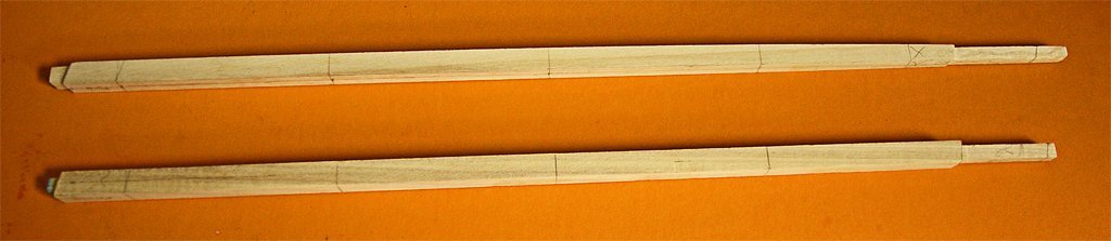
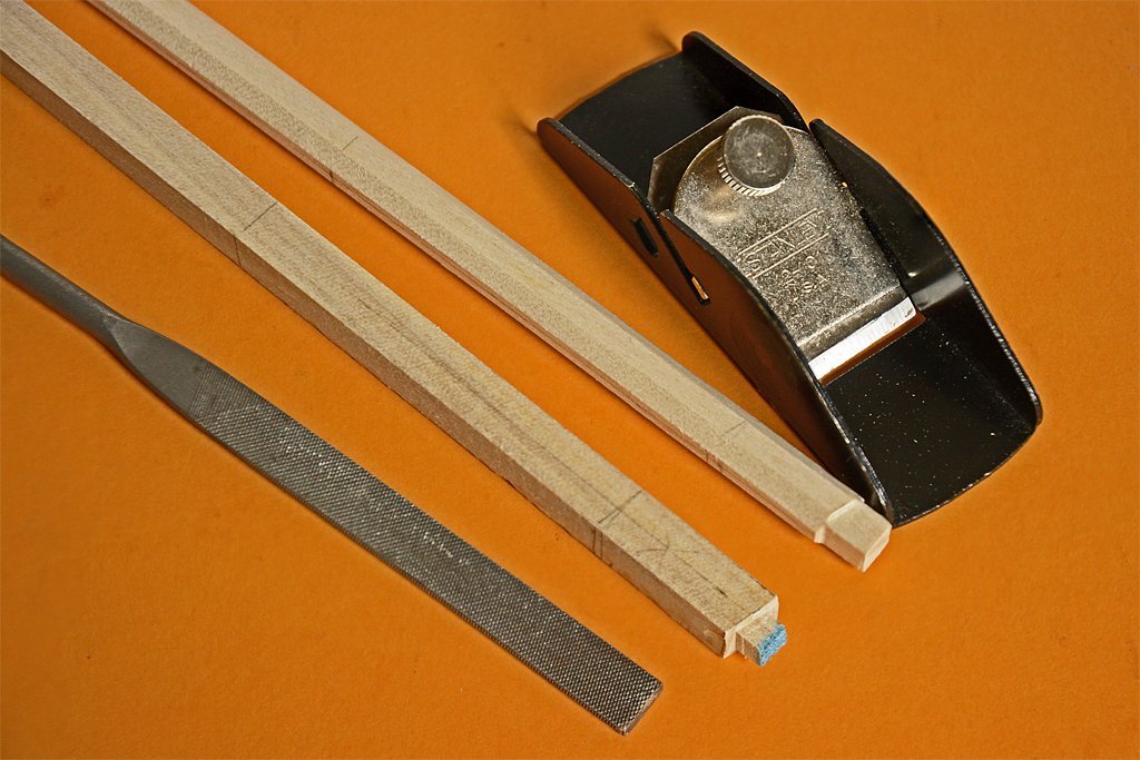
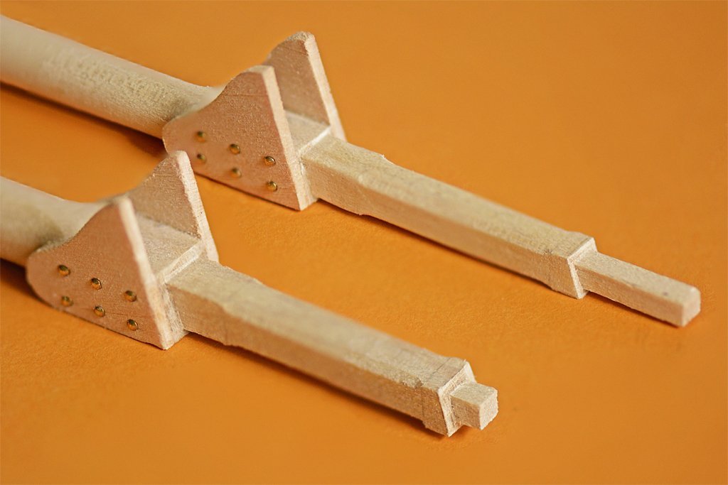
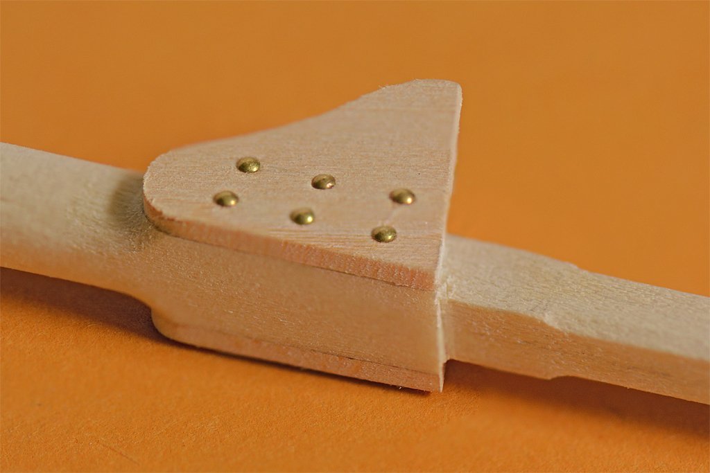
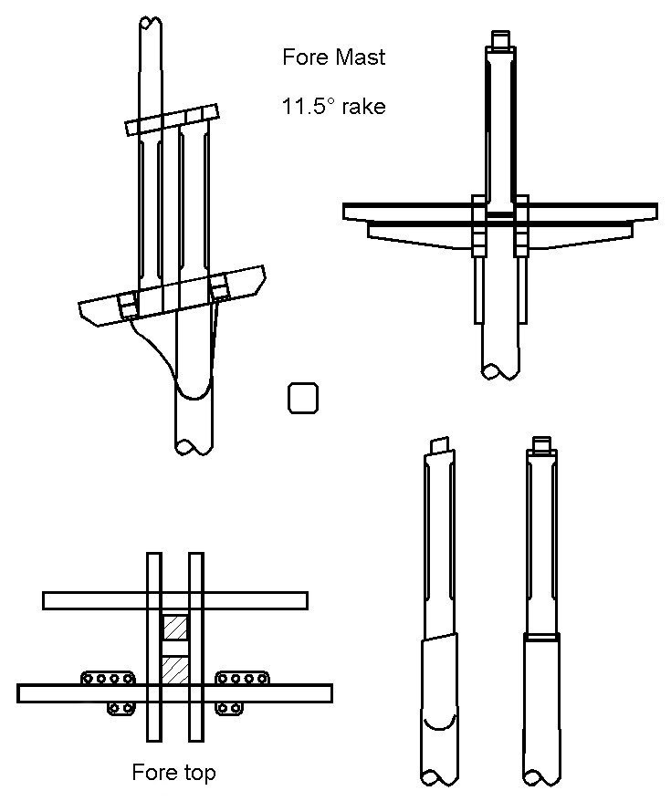
I am continuing with the masts. The first step was to reduce the 3/8 inch (9.5 mm) square dowels to the desired mast diameters of 0.350 and 0.322 inch (8.9 mm and 8.2 mm). The fore masts on topsail schooners often were larger diameter than the main masts. The fore mast carried square sails and their rigging in addition to the gaff sails so they needed to be sturdier. However, it was also common for both masts to be the same diameter. I used the Dremel power tool and "drill press" to cut off the excess material from the sides and create the rough taper. Then I sanded the masts down to the finished dimensions. The next step was to trim the square cross section to octagonal. For this I used a tiny Stanley plane that I have carried in my tool kit for decades. It made short work cutting the parts down to size, and I used the file to finish them. Then I planed the eight edges to get sixteen-sided pieces, again finishing the job with the file. After this I chucked the masts into a drill and sanded them with 100 grit sandpaper to finish rounding them. Again, I have to say it is really easy to make masts this way! The masts were rounded to just below the hounds and were left square where the cheeks would attach. Above the hounds the size was reduced to 0.219 inch (5.6 mm) square for the fore mast and 0.200 inch (5 mm) square for the main mast head. Part of the head was champfered and the top was trimmed to create a 0.125 inch (3.2 mm) tenon for the mast cap. The excess tenon length will be trimmed after the cap is in place. The cheeks were glued in place, and then I used 7 mm brass nails to simulate bolt heads. After the glue had dried I used round files to trim the square part of the mast round and curved to match the curvature of the cheeks. I should note that larger vessels often had much longer cheeks that extended down the mast below the hounds for a length about equal to the length of the mast head. They were also tapered toward the bottom. But smaller ships often just had this simple arrangement. Having completed the masts this far I was ready to assemble the trestletrees and cross trees for the top "platforms." They will look like this: The trestletrees run fore-and aft, resting on top of the cheeks, flush against the sides of the square part of the lower mast and top of the cheeks . Crosstrees run athwart-ships (port to starboard) and rest on the trestletrees (actually set into notches in the trestletrees). The after crosstree on the fore mast had fairleads to guide rigging coming from above. This looks pretty straight forward, but what should the dimensions of these pieces be? I obviously had something in mind when I created the drawing, but I didn't remember the source I used for the dimensions! So I went back through the literature and discovered a problem. I looked in eight different references, and most of them gave different answers! Anderson, R. C., "Seventeenth Century Rigging." 1955 Chapman, Frederick, "Treatise of Shipbuilding" ("Architectura Navalis Maercatoria"), 1820 Cock, John, "A Treatise on Mast Making," 1840 Hedderwick, Peter, "A Treatise on Marine Architecture," 1830 Kipling, Robert, "Rudimentary Treatise on Masting, Mastmaking and Rigging," 1864 Lees, James, "The Masting and Rigging of English Ships of War," 1979 Marquardt, Karl, "The Global Schooner," 2003 Mondfeld, Wolfram, "Historic Ship Models," 1989 The main problem is that most of these references do not mention schooners, and treat wooden vessels as if every one was a 100 gun square rigged ship of the line. Cock and Marquardt do describe schooner rigs but they give very different definitions for the dimensions of the parts of the tops. Another problem was that the older references used a different English than is spoken today - at least here in North America - and some translation was necessary. After wading through a lot of apparently contradictory formulas it was clear that they all gave pretty different results. Another problem was that most of the references described complex tops for the lower masts, again like would be found on a large man of war. The dimensions for these lower tops were always given in terms of the dimensions of the larger top platforms. Schooners had very simple tops with no platforms. Trestletrees The trestletree centers should be aligned with either the center of the lower mast, or the front edge of the lower mast top. Trestletrees were notched to hold the crosstrees. Length. The length of the trestletrees on lower mast tops were usually defined in terms of the top platform size, usually the same length fore-and-aft as the top platform, or 2/3 to 1/2 the top platform width. But that's not very helpful if there is no platform. One author says trestletree length was 5 times the diameter of the mast at the hounds (the hounds was the part of the mast the cheeks fastened to, just below the trestletree). Another author says the length was 5 1/2 to 6 diameter of the mast at the hounds. Other definitions are 3 3/4 inch per yard of the topmast length (0.104 times the topmast length), or 3 1/2 inch for every yard of topmast length (0.097 times the topmast length). I used fairly average mast lengths and diameters for my schooner model. The foremast diameter at the hounds is 0.270 inch (6.8 mm). So the trestletree length would be 5 to 6 times this diameter, or 1.35 to 1.62 inches (34.3 mm to 40.8 mm). The topmast length is 7.5 inches (190.5 mm) so the trestletree would be 0.104 to 0.097 this length, or 0.78 to 0.73 inches (19.8 to 18.5 mm). Clearly these different methods do not generate the same results! Height The height of the trestletrees is said to be 1/2 the diameter of the mast at the hounds, but a different author said it was 5/6 the diameter of the mast at the hounds. Another author said the height was 1/2 the diameter of the mast at the partners (the partners is where the lower part of the mast passes through the ship's deck). One source says the height in inches was the topmast length in feet divided by four, less half an inch. Or the height is 1 inch per foot length of the trestletree (1/12 the length or 0.083 times the length). But another author say the height is 1 1/8 inch for every foot of trestletree length (length x 0.094). Using my model mast dimensions I get a trestletree height of 0.135, 0.23, 0.175 or 0.145 inches (3.4, 5.7, 4.4 or 3.7 mm). It's better than the length calculations, but still highly variable. Width The trestletree width is given as 1/3 the diameter of the mast at the hounds, or 3/7, 1/2, 2/3 and 5/7 of the trestletree height. Take your pick! Crosstrees The crosstrees were notched to fit into the notches in the trestletrees, typically the depth of the notch was 1/2 the crosstree height. Length The length of the crosstrees for the lower masts was often given as a fraction of the ship's beam width. It was 1/2, 5/9 or 11/24 of the beam width. Sometimes it was specified relative to the trestletree length, 1 1/3 to 1 2/3 the trestletree length. One author said it was the length of the masthead, or a little more. Height The crosstree height was usually a fraction of the trestletree height, 3/7, 1/2, 7/8 and 1 times the trestletree height. One author said it was 1/13 the trestletree length. Width The crosstree width was said to be 7/8, 9/10 , 1 or 1 1/4 that of the trestletrees. Or it was 2/3 or 5/6 of the crosstree height. **** Well that is as clear as mud! I guess I will just use the original dimensions I came up with for the drawing shown above. No matter what they are they will probably be close to what one or two of the authors said they should be!
-
Dove by jlefever - 1:48 - Pinky Schooner
Dr PR replied to jlefever's topic in - Build logs for subjects built 1851 - 1900
Jim, The two vessels do make for some interesting comparisons. The pinky schooners were a later step in the evolution of the schooner from the period I am modeling. You are right that my build is not an accurate model of a real vessel, and it is something of a hodge podge of fittings and deck furniture from the early 1800s. For me it is a learning experience, and learning new things is one of my favorite things. -
OS50, Thanks. I have seen several variations of designs for jacks. I think some may have been for State vessels and some private. We often forget that the US was originally a loose confederation of colonies and some had vessels of their own. And the US Navy didn't have formal rules for painting and such until well into the 1800s. A lot of what a vessel looked like was the prerogative of the ship owner or Captain. Many American vessels followed British practice. So unless you have information specific for a particular vessel I guess you can do pretty much as you please with a model so long as it isn't too far out of line. Right now I am trying to determine the color of the masts, mast tops, spars, bowsprit and bowsprit head. In the late 1800s white was popular for the doublings on the masts. But I read somewhere that white wasn't used early in the century because it would be too easy to spot at a distance. Frankly, I think this is nonsense! A little bit of white on a mast carrying huge sheets of canvas isn't going to make any difference. At sea a tall mast with sails cannot be camouflaged! Some people say the tops were painted black, and I have seen some models painted that way. But I haven't found anything definite about the color of masts and spars.
-
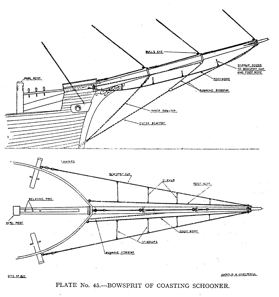
Underhill ("Masting and Rigging the Clipper Ship & Ocean Carrier," Plate 45, page 250) calls the ladder-like lines running between the bowsprit shrouds (or bowsprit guys) and foot ropes the "stirrups." They "hang" from the guys to support the foot ropes, although they do not hang beneath the guys but angle inboard to the foot ropes. While these lines (and nets in the same position) might make working on the bowsprit and jib boom safer, one of their purposes was to catch sails when they were lowered and prevent them from dragging in the water. Note: This shouldn't be confused with stirrups hanging from spars to support the foot ropes, although they serve the same purpose. Following this nomenclature, the upper lines from the plates on the sides of the hull would be the bowsprit guys and the lower lines would be the foot ropes, with stirrups between them. The upper (smaller) plate on the stem might be for an inner bobstay, while the larger one at the waterline would be an outer bobstay. At least this gives you an excuse to rig them all.

-
Richard, Good point about temperature effects. Putting styrene (any plastics) on wood is definitely not a good idea if the model will be exposed to direct sunlight for long (as will happen with R/C models). Plastics have a relatively large coefficient of thermal expansion compared to wood, fiberglass or even metals. On another forum a fellow from down south in Australia built a 1:72 aircraft carrier with a wooden frame and styrene flight deck and sides. When heated in the sun the plastic expanded faster than the wood. The flight deck buckled and some of the side pieces buckled. As an example, a 6 meter piece of styrene will become about 5 mm longer with a 20C temperature rise. Wood does not expand that much. There is no glue that will hold wood and plastic together with that much difference in expansion. Considering the size of your model it is very wise to use wood sheeting!
- 454 replies
-
- 4
-
-
- Union Steamship Company
- Stepcraft 840
- (and 3 more)
-
You can fiddle with the exposure time to fine tune some dimensions. Long exposures cause things to be fatter. The light scatters through the resin. This allows some resin to be cured around the exposed area, adding to the intended dimension. Also, some light diffuses through thin sections, causing additional resin to cure "on top" of previous layers. I have found that minimum exposure times work best for fine details. But I still can't get very small holes (0.010 inch or 0.25 mm) to come out even though this is 5x the diameter of a single pixel on my machine. Maybe this is just because I haven't been able to wash uncured resin out of the holes before I cure the pieces?
-
Actually, some vessels did have "piggybacked" shrouds - two per chain plate. See Petersson's "Rigging Fore-And-Aft Craft" page 73 for an example. It was taken from a period schooner model. Two shrouds to the lower mast top was common on schooners without square sails. Often there were no ratlines. The beauty of the fore-and-aft rig was that almost everything could be done from the deck, without anyone going aloft. If you needed to go aloft you climbed the mast hoops or were pulled aloft with a tackle.
-
Kevin, I have used the sunlight technique to clean the IPA (and water for water washable resins). I have also just put the container in my light box and zapped it for an hour or so. You have to use a clear glass container that passes UV light (many plastics do not). It worked even here in Oregon where it is mostly cloudy from November to May. It takes a while (a week), but the resin cures into a soupy suspension. I pour it through a coffee filter to recover the alcohol (I use denatured (95%) ethanol camp fuel - it's cheaper by the gallon than 95% IPA). I have two wash baths. The first has been used before to wash prints, and the second is fresher alcohol. Like you, after the first bath becomes cloudy I put it out to cure, switch the second bath for the first, and start a new clean second bath.
-
Dove by jlefever - 1:48 - Pinky Schooner
Dr PR replied to jlefever's topic in - Build logs for subjects built 1851 - 1900
Jim, The model is looking good! I would say your soldering technique is also pretty good. One trick I have learned is to use a brass or steel wire brush in a motor tool to polish the soldered joints. It makes a much shinier finish than I get with files. But you need to be careful, especially with the steel wire brushes. They can remove a lot of solder quickly if you use too much pressure. In fact, I use this technique to remove excess solder to get nice clean joints. Another trick I have used for decades to fashion things like your wyes is to cut a narrow strip of brass and fold it to make an ear. Then I clamp the ear in pliers and open the strip so I have an ear at right angles to the rest of the strip. After adding solder to the ear to prevent the sides from spreading I wrap the strip around the spar to the next point I need an ear and repeat the process. For the last ear I just bend the strap so both ends come together and solder them. Then I cut them off to the right length for the final ear. It takes a bit of practice to get the ears to come out at the right angles, but the resulting part is very strong. You can practice with a strip of paper to get the dimensions right. Finally I drill out the holes in the ears and shape them with a file. Here is a simple example at the bottom of the dolphin striker.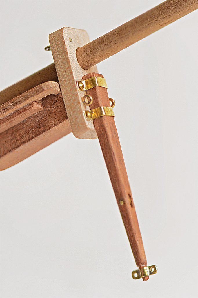
-
Gregg, Your build is coming along nicely. Like George said, don't worry about the pump location. I don't recall the thread now, but in another build by a pretty experienced modeller a lengthy discussion ensued over the location of pumps - whether they should be farther aft or midships. What appeared to be original plans seemed to show them midships, even though this point was about a foot above the low point of the bilges. It was an interesting, but inconclusive discussion. For a ship pitching in rolling seas just about every point of the bilges is the lowest point at some time. But in port some water will accumulate at the lowest point. So chalk this one up as a learning experience. I have had a lot of learning experiences in my schooner model build, and there will be more to come!
- 65 replies
-
- 2
-
-
- Ballahoo
- Caldercraft
- (and 1 more)
-
A thin two-part liquid epoxy "paint" would work to attach the styrene hull plates to the wood. It will give you time to adjust the position before it hardens and will give a very strong bond. For attaching the thin styrene rods to the grooves in the plating I would use styrene cement (MEK or methyl ethyl ketone). Just use a small paint brush and apply a thin coating along the seam. The MEK will flow immediately into the grove and melt the two parts together. It dries in a few seconds and will not mar the surface of the parts. You might also consider using very thin square cross section styrene strips instead of round strips. This will leave a "V" shaped bead that could be sanded/scraped down for a lower profile weld bead than the semi-circular bulge with the round strip.
- 454 replies
-
- 3
-
-
- Union Steamship Company
- Stepcraft 840
- (and 3 more)
-
Mike, The shrouds will not be the same length exactly. The forward shroud is close outboard of the mast and the aft shroud is farther back. Since the mast has some rake (leans aft) the distance from the deadeyes to the mast top will be a bit different.
-
George, I thought about a jackstaff, but it I don't know if smaller vessels flew the jack. Although the US Navy technically had a Union Jack with white stars on a blue field (like the US Ensign). But the first Navy Jack was the "Don't Tread On Me" flag with red and white stripes and a rattlesnake. I don't know when it became common practice to fly it - and where. Some illustrations show the jack flying from the top of a mast. Virtually no drawings or illustrations of American schooners show a jackstaff or jack. But this could be simply due to the fact the jack is flown only in port when anchored, moored or tied up to the pier. Even in the Navy today the jack is raised when the anchor is dropped or the first mooring line goes over to the pier, and it is pulled down when the ship signals "under way" (three toots on the ship's whistle). Most drawings and illustrations show vessels at sea, when the jack wasn't flown. Very few of these drawings show a jackstaff. It is common on modern ships to lower the jackstaff after getting underway. I wonder if it was the practice in sailing ship days to remove the jackstaff after getting under way? Having a pole sticking up on the bowsprit would certainly foul a fore sail when the vessel tacked. I have seen a drawing somewhere of a jackstaff that was attached to the bowsprit cap with metal straps (without a notch in the cap).
-
It is definitely a pond yacht! Real schooners did not have the mast doubling (where the lower and upper masts overlap) anything like what you have on the model. On real ships the shrouds would loop around the mast head, with both legs of the loop coming down on the same side of the ship. On the model I suppose the shrouds may have been fastened to the eye bolt loops below the spreaders. I wonder if there is an Internet forum for pond yachts? If you can find someone that sells modern pond yachts they might know if there is a Forum.
-
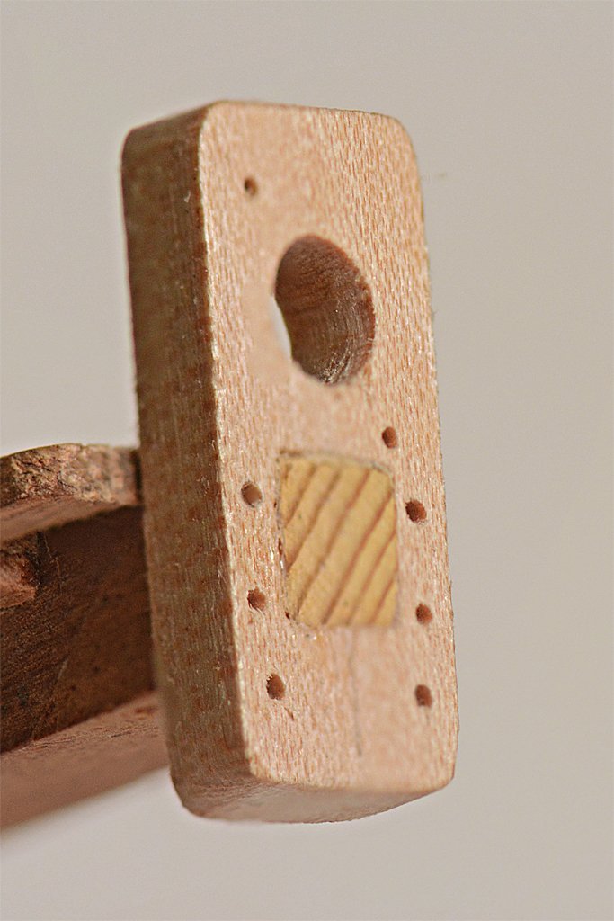
To finish the bowsprit cap and install the dolphin striker I had to make a few parts and finish the fitting of the cap. I drilled holes for the ring bolts and dolphin striker fasteners before attaching the cap to the bowsprit. The tenon was a bit too long so I used a file and sandpaper to finish the end of the tenon smooth with the face of the cap. The dolphin striker straps were cut from 0.005 inch (0.127 mm) brass sheet, and the ring bolts are from 0.020" (0.51 mm) brass rod. I soldered the gap in the ring bolts. The "bolts" are 7 mm brass nails that have been cut to length. I cut a short piece of 0.0625 inch (1.6 mm) brass tubing for the sheave in the dolphin striker and pined it in place with brass rod. The fitting at the bottom of the dolphin striker was made from 0.005 inch brass sheet that was folded and soldered. It is for the martingale stay and backstays. Assembly was pretty straight forward. I used Duco cement to glue the bowsprit cap in place, and also put a bit in each of the holes for the ring bolts and nails. I probably spent more time on my hands and knees looking for wayward tiny parts than I did with the assembly. The ring bolts on the face of the cap are there in case I discover I need them. I originally thought that one would be used for the traveler outhaul, But if I use this configuration the flying jib stay would be attached to the traveler and run through a block or sheave at the mast top, and back down to a tackle somewhere on deck near the base of the fore mast. But this is already too crowded with belaying points. The sheave in the dolphin striker will allow me to attach the flying jib stay to the mast top, run it through a thimble on the traveller, then through a sheave/block at the end of the jib boom, down through the sheave in the dolphin striker and then to a tackle attached somewhere in the bow. In this way the stay acts as a support for the sail and as the traveler outhaul. The two ring bolts on the back side of the cap are for the jib boom outhaul. I need to put a sheave in the base of the jib boom for this rig.
- 421 replies
-
- 14
-
-