


KurtH
-
Posts
449 -
Joined
-
Last visited
Content Type
Profiles
Forums
Gallery
Events
Posts posted by KurtH
-
-
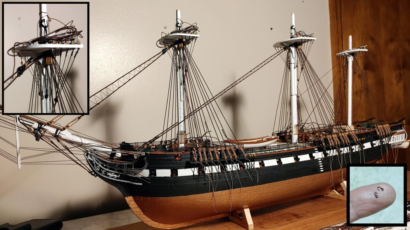
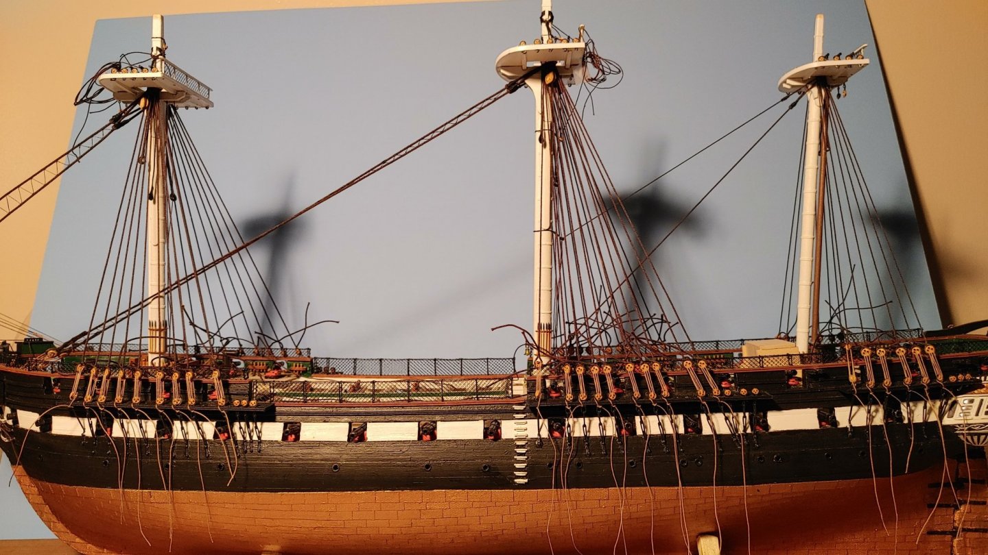
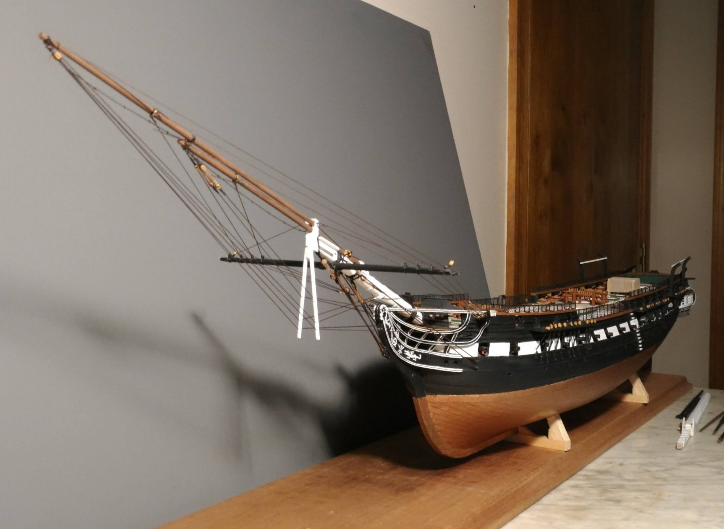
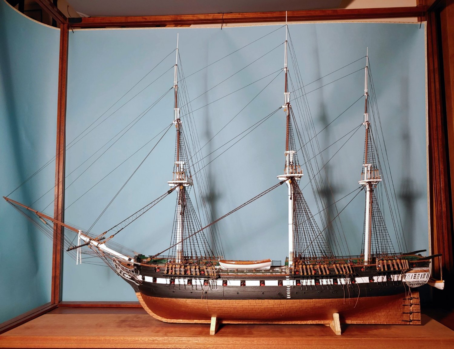
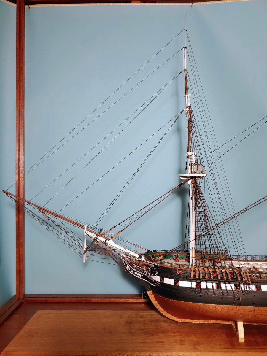
Another milestone reached. All standing rigging lines are in place. Backstays can still be cast off if they obstruct installation of running rigging.

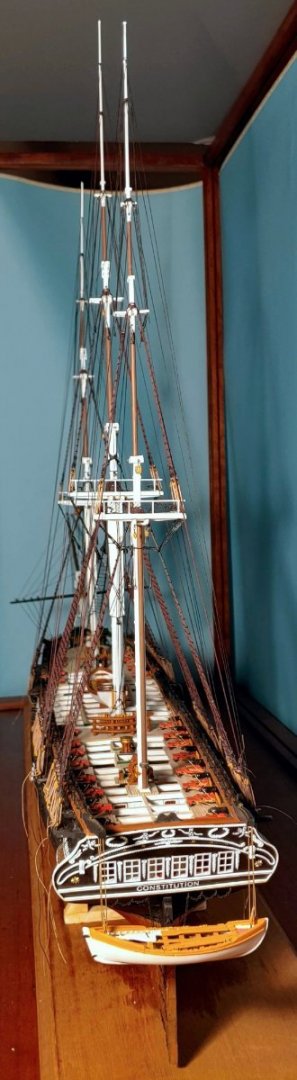
Yaay!
- Shotlocker, wtimlen, mort stoll and 8 others
-
 10
10
-
 1
1
-
Thanks so much Mort for your advice and encouragement!
Thanks so much Bill for the info. I will check out that site.
-
All main mast rigging in place. T'gallant and royal shrouds and stays are glued in place with a spot of CA, but can be unglued with debonder (acetone?) if need be. Tails left long for now. Fake eye splices and trimming to be done when I can be reasonably sure that no additional adjustments are necessary. Hard to know when that will be when I have no prior experience in this sort of thing. I am thinking that the tyes may affect the backstays, and the braces may affect the fore and aft stays. Lifts, jeers, and trusses would probably make no difference (?). Gluing in the fore and main fife rails permanently will make access to the top mast stays and the t'gallant preventer stay eye splices at the deck impossible, so I will need to be sure these stays are stable before beginning the running rigging.
-
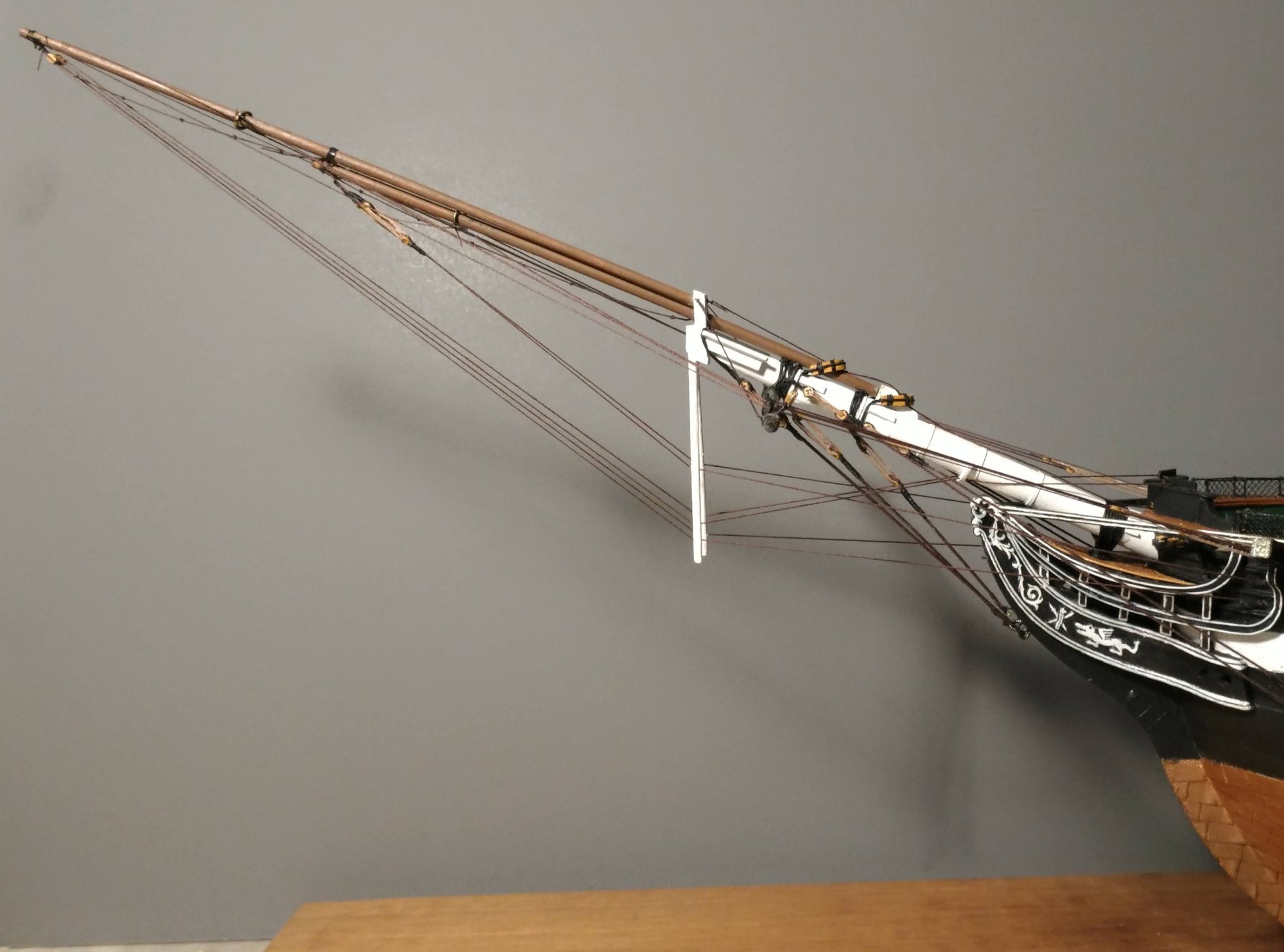
There. That's better. All foremast rigging in place. Tails are still left long and backstay seizings left undone to allow for future adjustments in the tensioning.
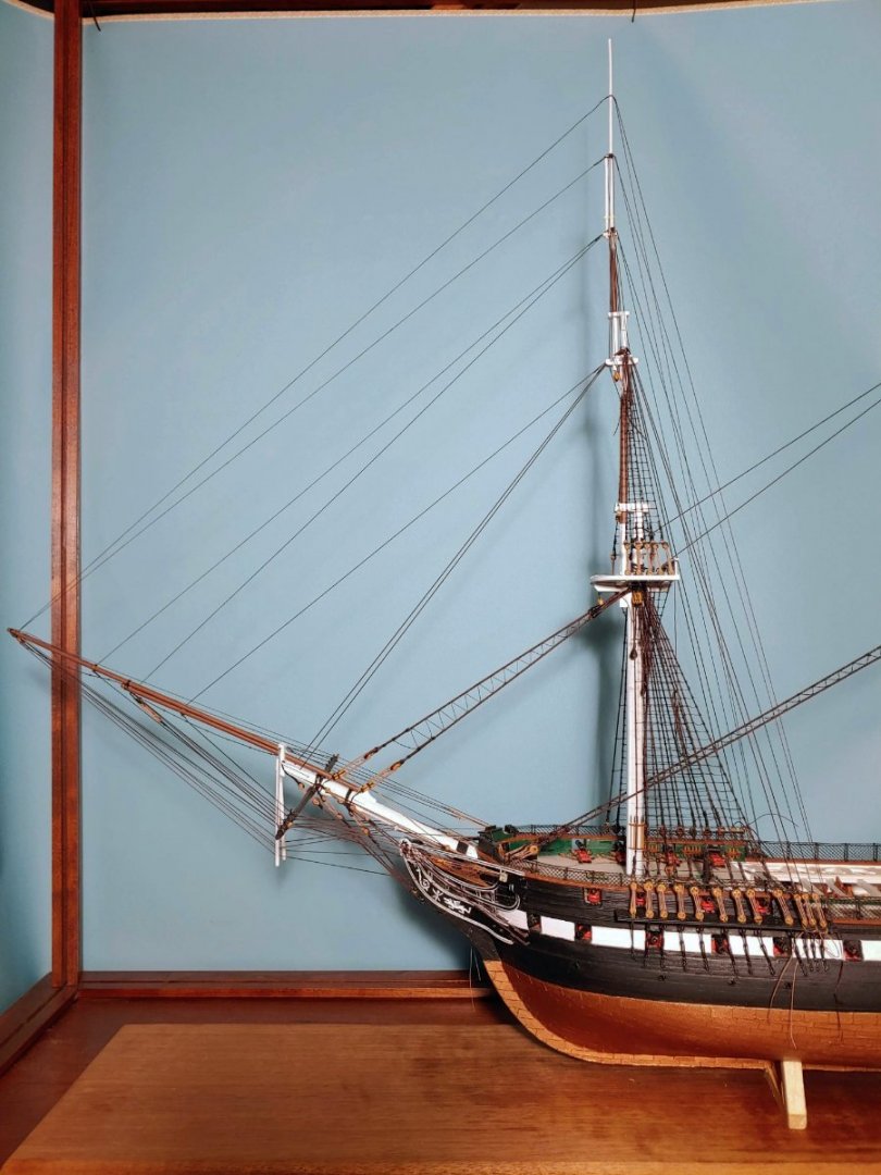
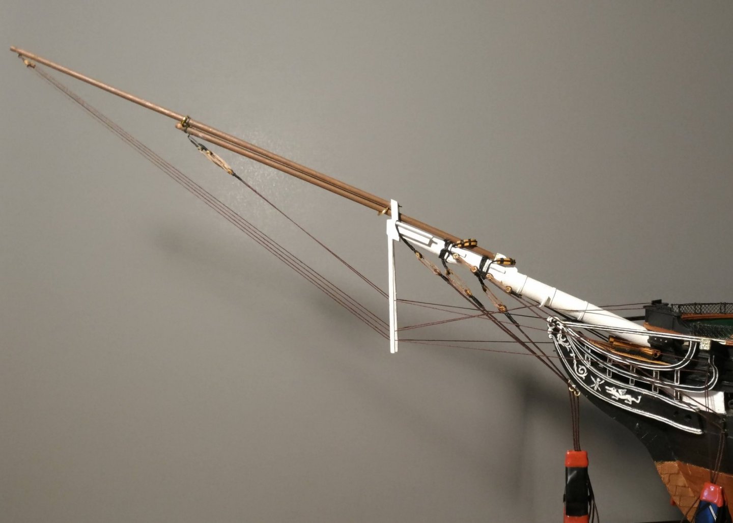
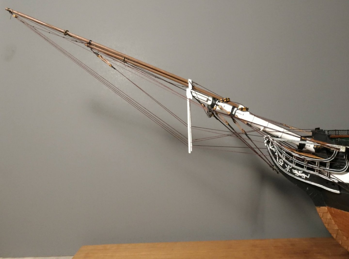
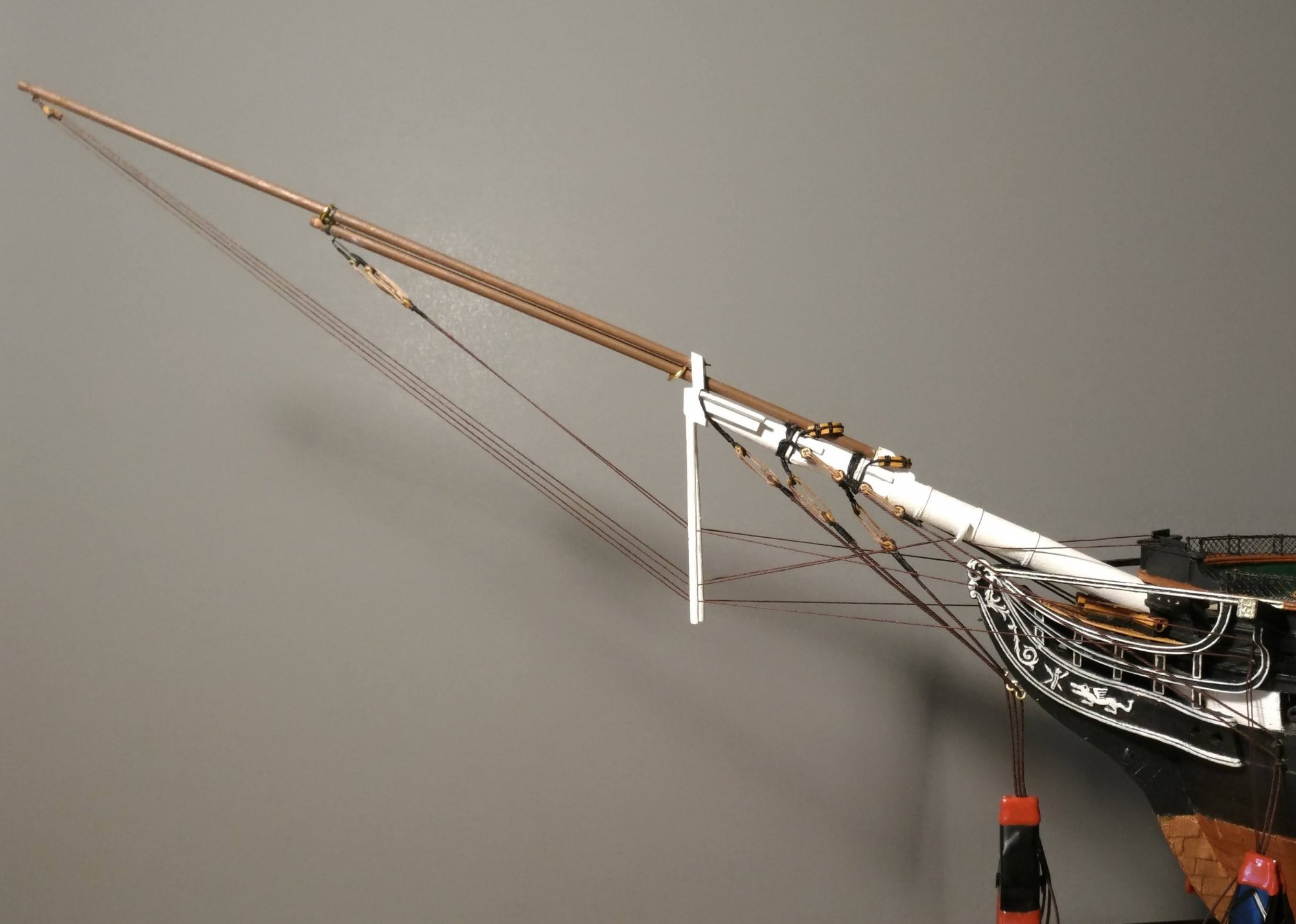
Now that all the upper stays are in place, the final appearance of the bowsprit rigging can be seen. It more resembles the present configuration than it does the more complex rig shown in the BJ plans.
-
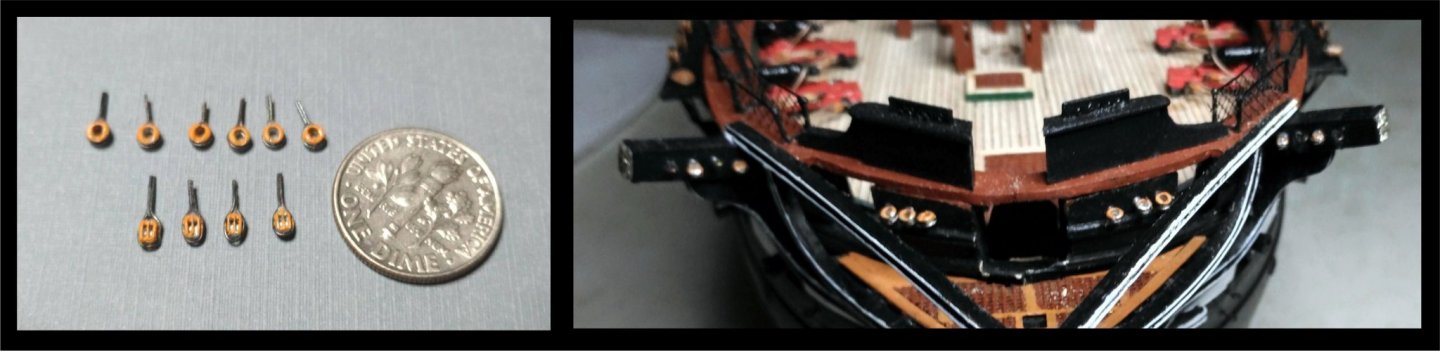
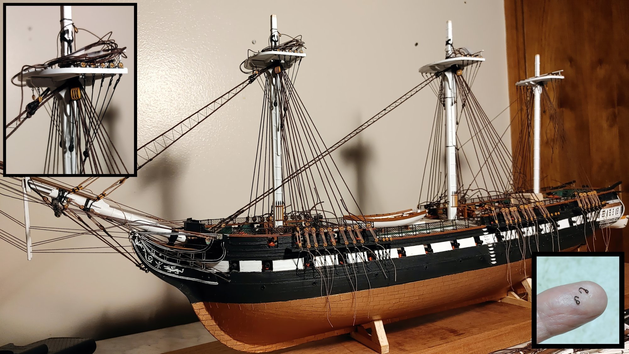
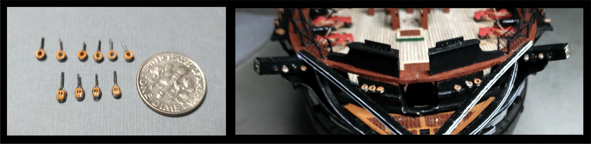
Out of curiosity, I have looked at other builds using ready made sheathing plates and have found, in all fairness to BJ, that all the ones I have seen so far have nail heads that are out of scale. Of these, the Revell plastic model comes the closest to having the right size nail heads, but even they stick out more than these nails do:
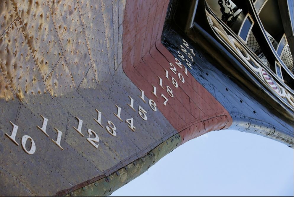
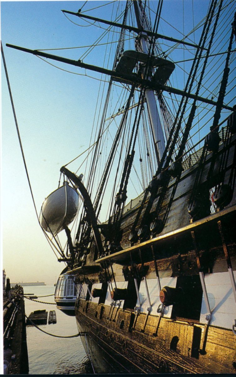
Incidentally, it seems to me that those of us who, like me, are distressed to see irregularities in their work when photographed super close up, can take some comfort in this photo.
- etubino, ccoyle, Bill Morrison and 3 others
-
6
-
Thank you so much Allan. I really appreciate your kind words. Thanks for the photo. I will add it to my collection of ship photos. You are quite right about the nail detail. It is also true that the thickness of the BJ plates is well out of scale. I am thinking that if I do coppering on my next project, copper tape might be the way to go, now that I have seen the way it really is:
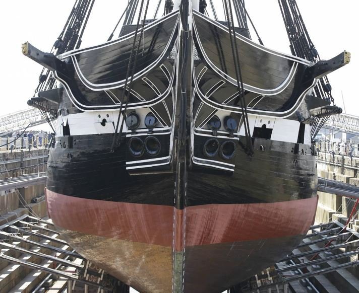
At the time I did the coppering, I didn't know nuttin' about it. I am not even sure how I could go about making detail that small at 1/96. As you say, better to not have it than make a mess out of it. Thanks for the confirmation about the overlapping. I have seen sources and builds in which it is done the opposite way.
- schooner, SteveLarsen, Bill Morrison and 1 other
-
4
-
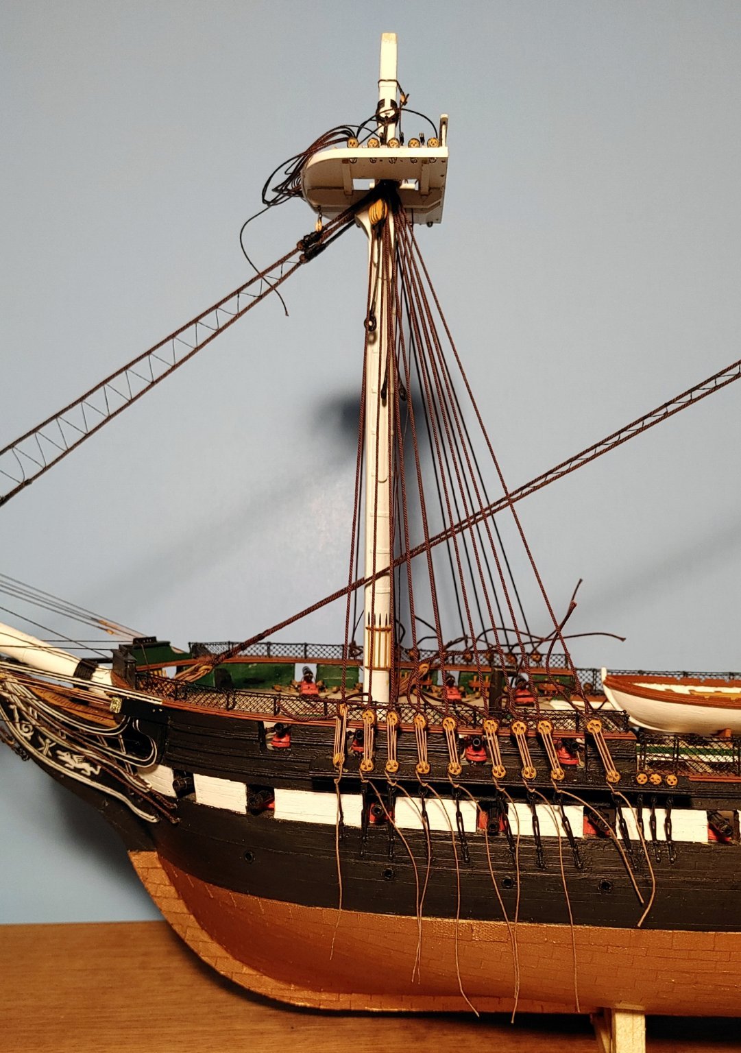
Photo of the upper rigging of the foremast in progress to show that I have not abandoned the build. A photo of a more finalized version
will follow. Tails to be left long until the very last stages of the rigging process. LInes that remained taut for months are now slack and have to be re-tensioned. Fortunately, I did not seize these, and debonder will allow me to loosen and redo the hitches.
- Tom E, SteveLarsen, WalrusGuy and 6 others
-
9
-
Yes. I laid the gun stripe planks first so I could sand them thinner without disturbing the planks which are above and below it. I get all my planking stock from BJ.
- Bill Morrison and Avi
-
2
-
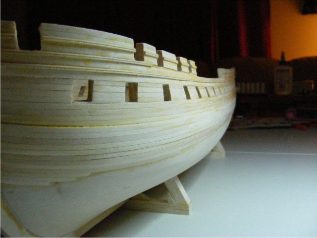
I see the wales as being the thickest, the three strakes above that and those above the gunports as being thinner, and the strakes between the gun ports as being the thinnest. I used 3/32" thick planks sanded down to size for the wales, .020" BJ planks sanded down for the gun streak planks, and .020" BJ planks for the rest.
-
This photo shows 3, as does the Revell model. The planks are just a bit thinner between gun ports.

Hope this helps. Actually it really is your choice.
-
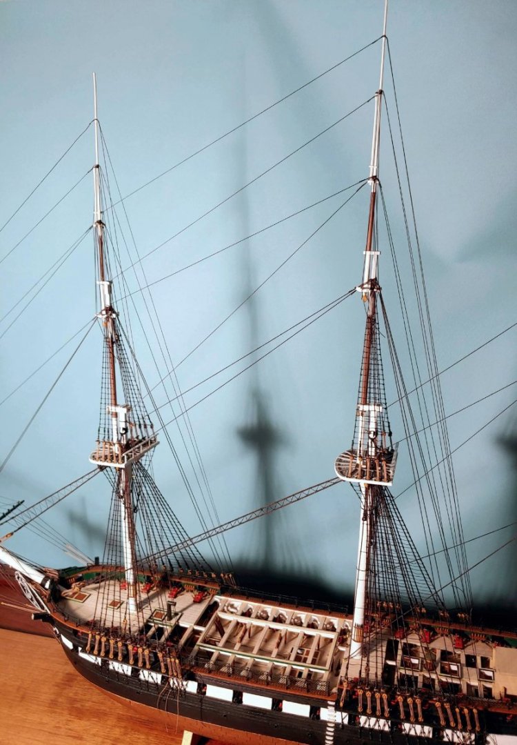
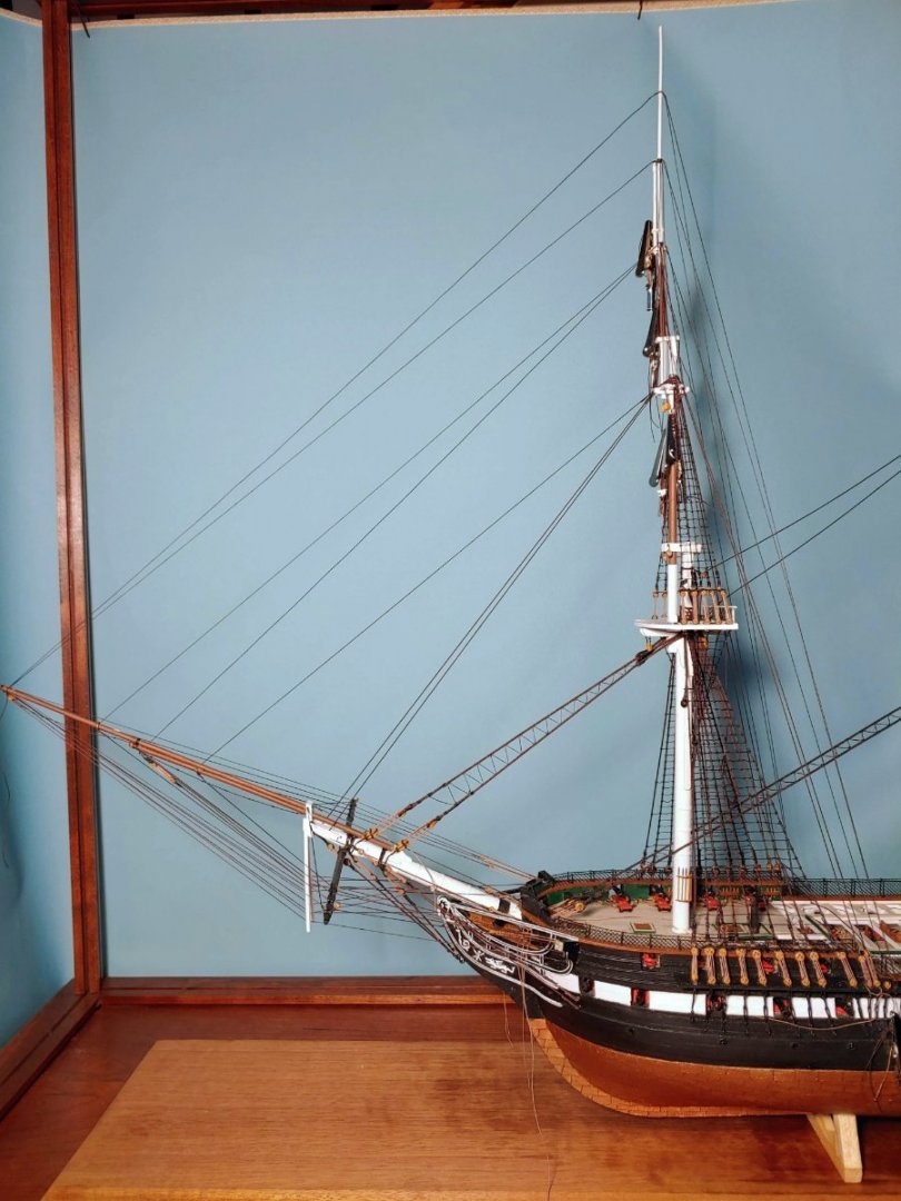
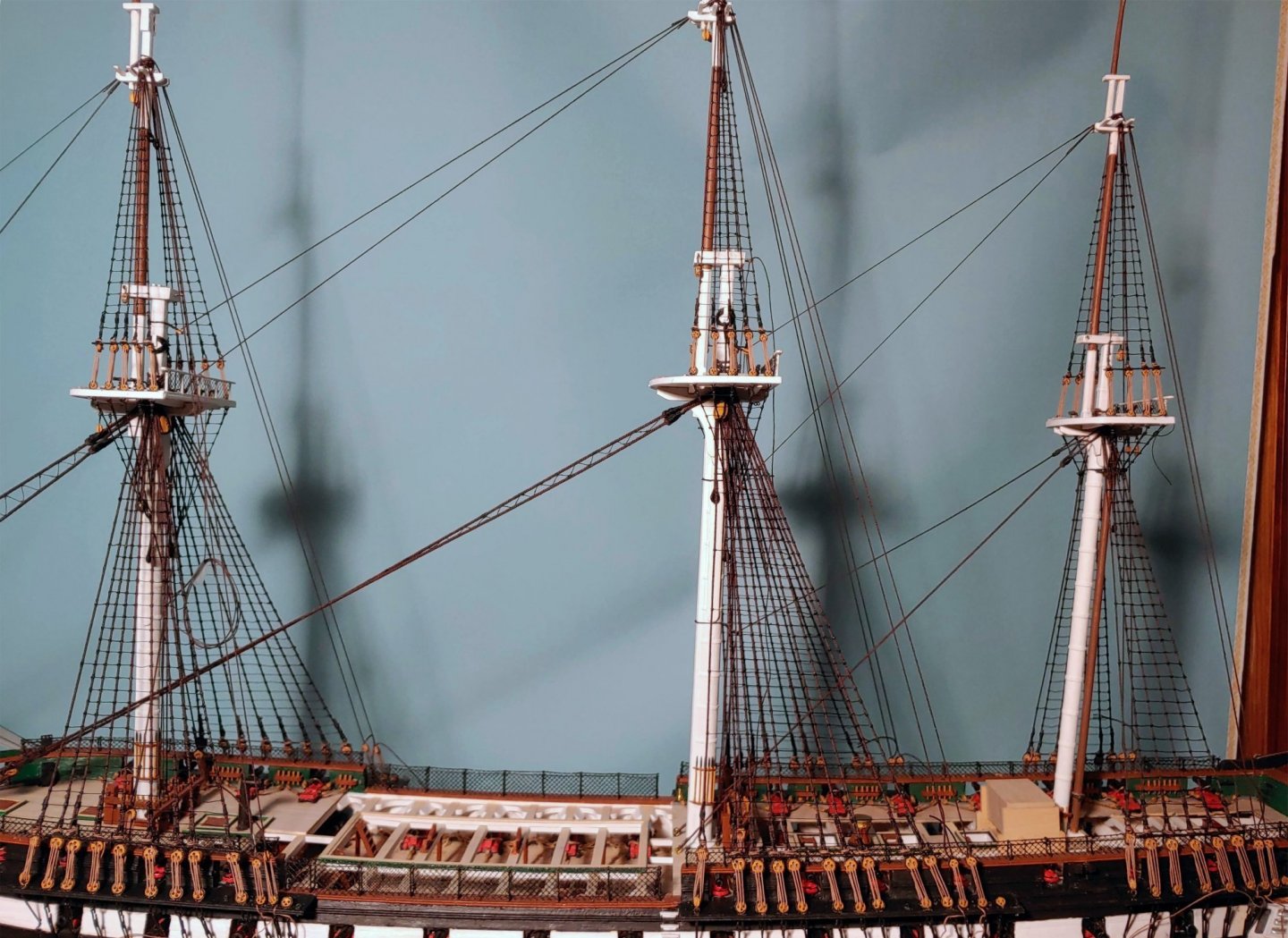
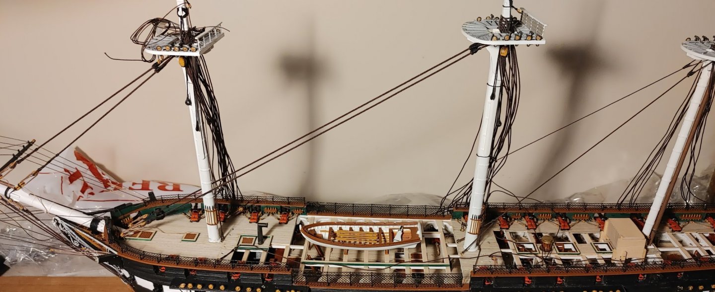
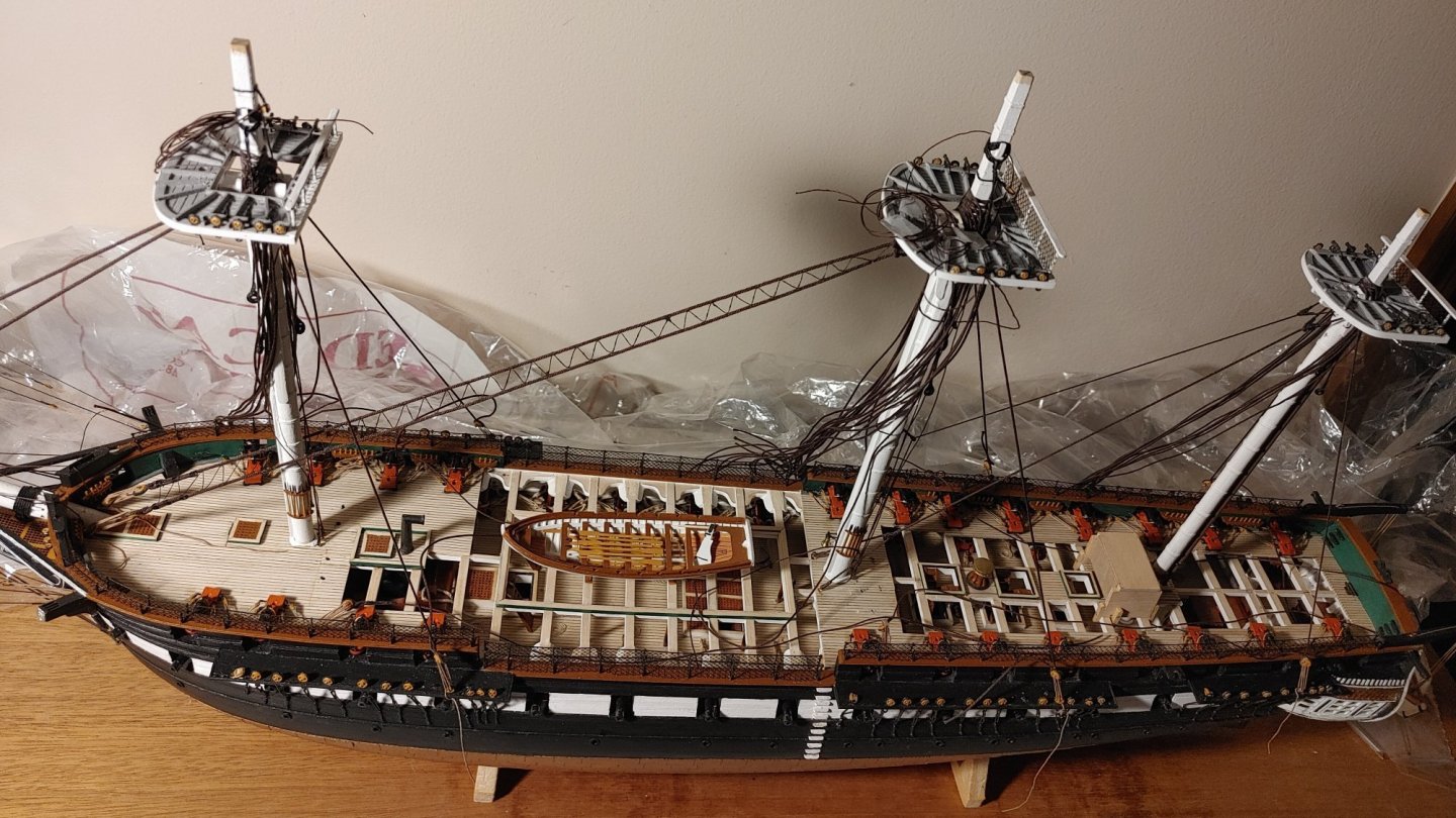
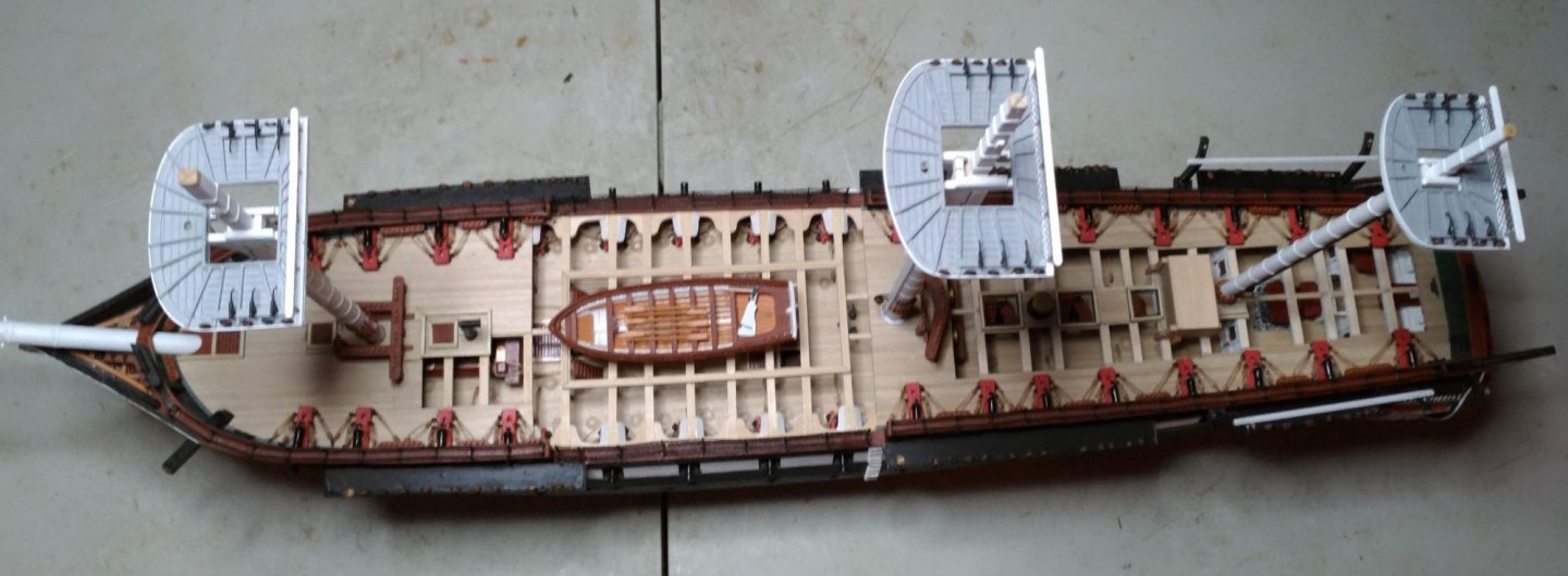
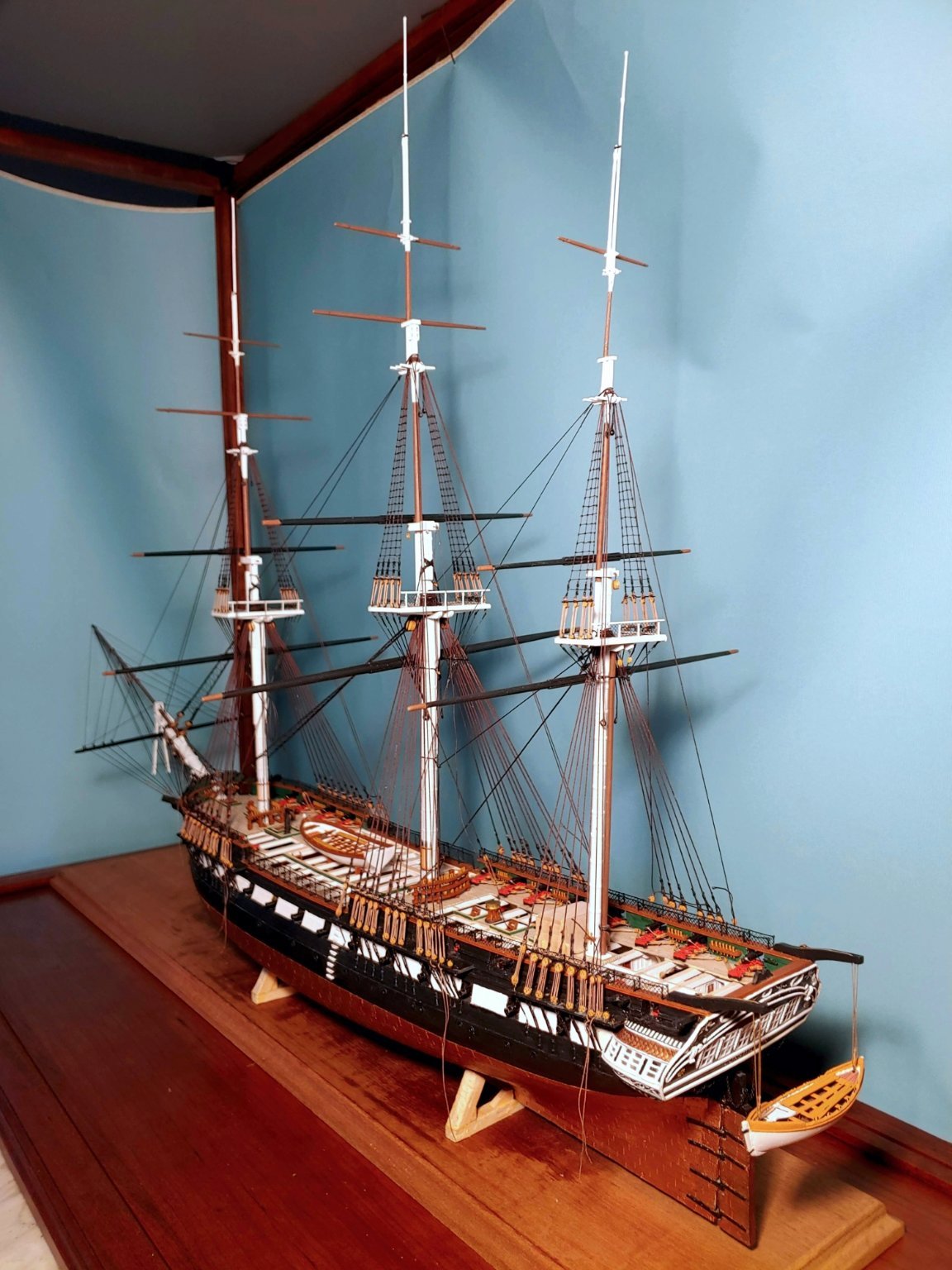
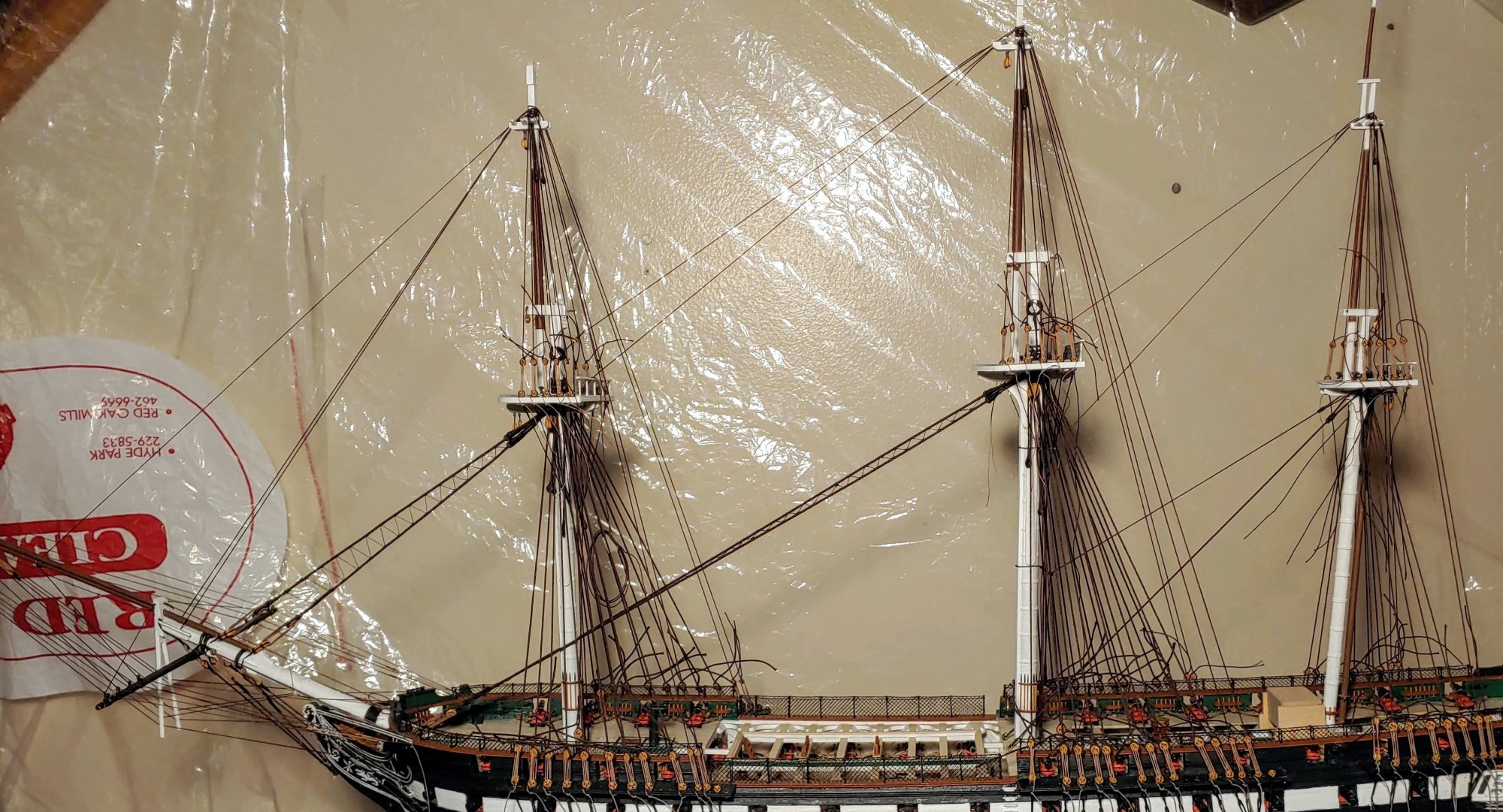
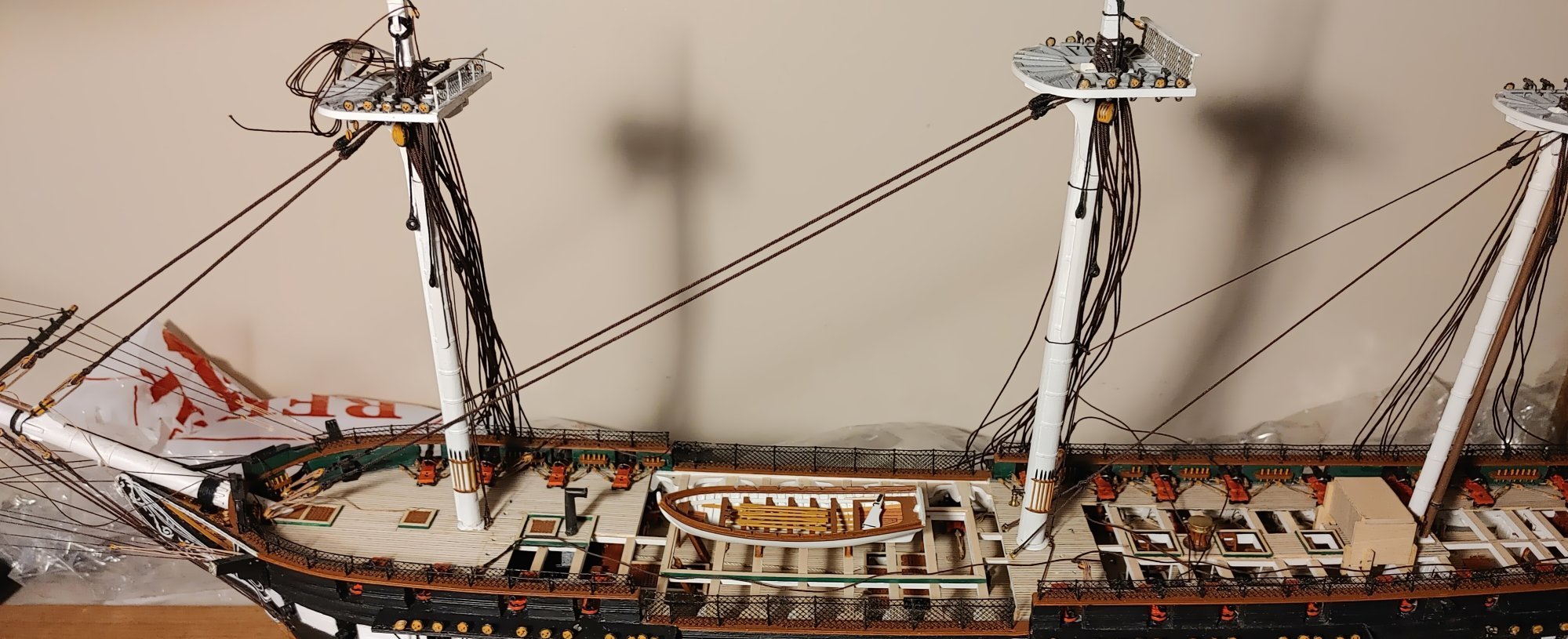
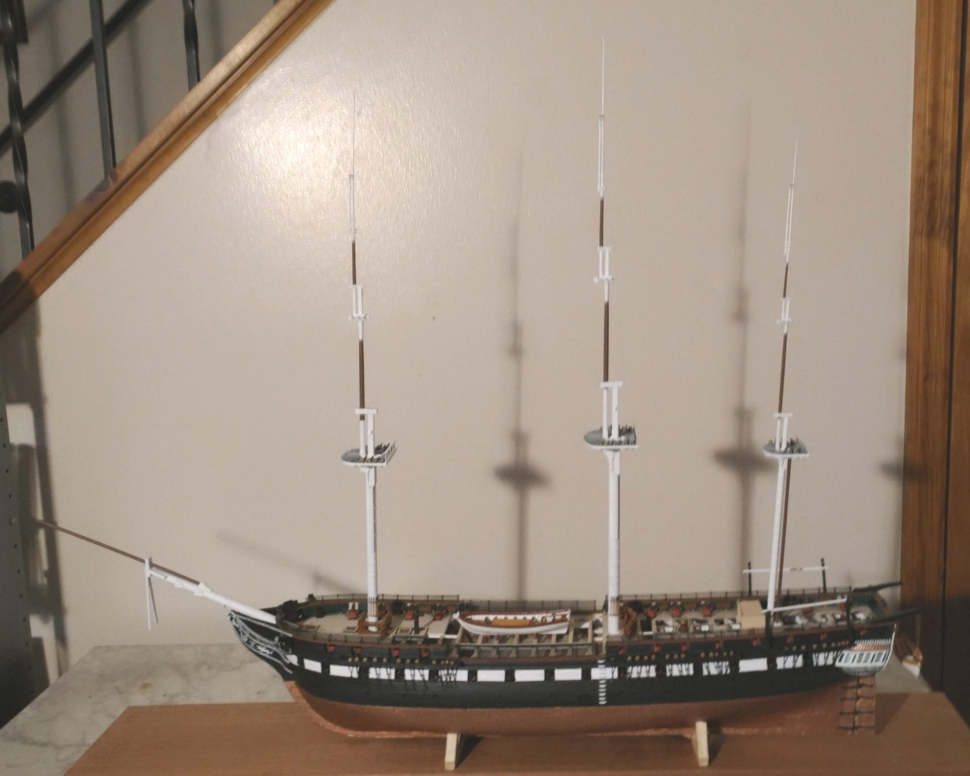
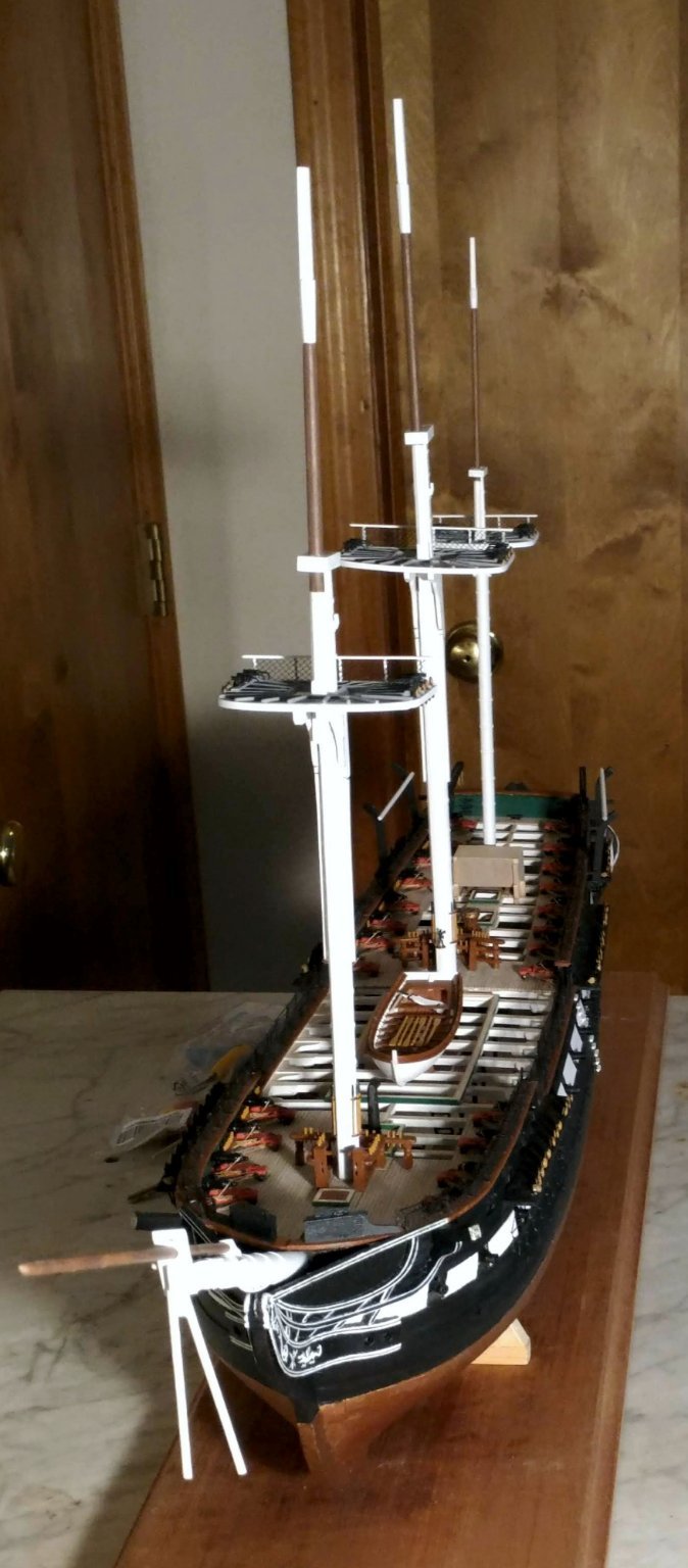
I recently had visitors in, so I temporarily attached the yards to the model. It makes a nice preview of what the model will look like:

- mort stoll, BenD, etubino and 6 others
-
9
-
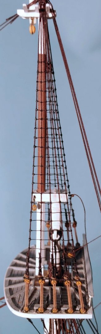
The lower shroud ratlines
This is the first new post of this log.
In rigging these ratlines, I found that the topmast backstays became a serious obstacle, so I undid the lanyards and cast them off.
Here are some shots of the ratlines rigged on the lower and futtock shrouds:
Them's a lotta ratlines. As they say, onward and upward. T'gallant shrouds and stays to be rigged next.
- BenD, mort stoll, SteveLarsen and 7 others
-
10
-
Topmast shroud ratlines
I decided to rig the topmast ratlines first. I am not sure that I will do that in the future. I have seen builds in which all the details of the lower mast rigging is completed before the topmasts are even mounted. Apparently, it worked for them. Something to think about in future builds. The ratlines were rigged using BJ's .005 cotton line. It is a bit stiff, which means that the knots must be very tight so that they close properly, and do not show daylight with loops sticking out, but which also means that the ratlines have a stabilizing effect on the shrouds. I used cow hitches on the outer shrouds and clove hitches on the others. The cow hitch does not have an end sticking out sideways, but does not hold very well, requiring glue to secure it. Much has been said about how boring this process is, but I found that tedium was the least of my problems. For me, keeping the ratlines reasonably straight, and the shrouds perfectly straight was an immense challenge. I probably should not detail my ratline rigging technique, as it is unique, time consuming, and most likely not the best way.
I did, however, adopt a widely used method for keeping the ratlines properly spaced and the shrouds straight - a cardboard pattern with the ratlines and shrouds drawn, inboard of the shrouds:
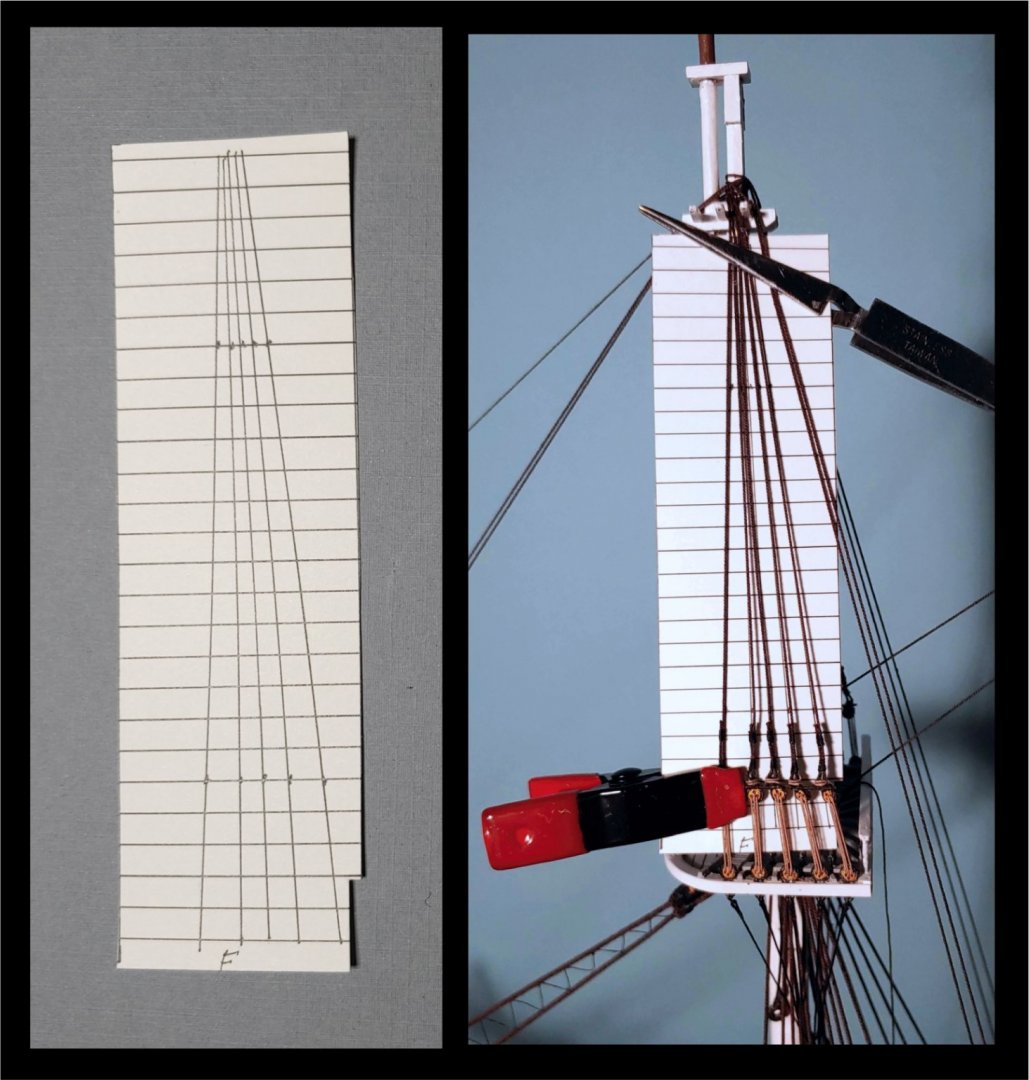
Here is what I ended up with:
This brings me to where I was when I deleted my entire log. I would like to thank those who encouraged me with their "likes", and especially Mort Stoll for his constant support throughout the process.
- rvchima, oneslim, Bill Morrison and 4 others
-
7
-
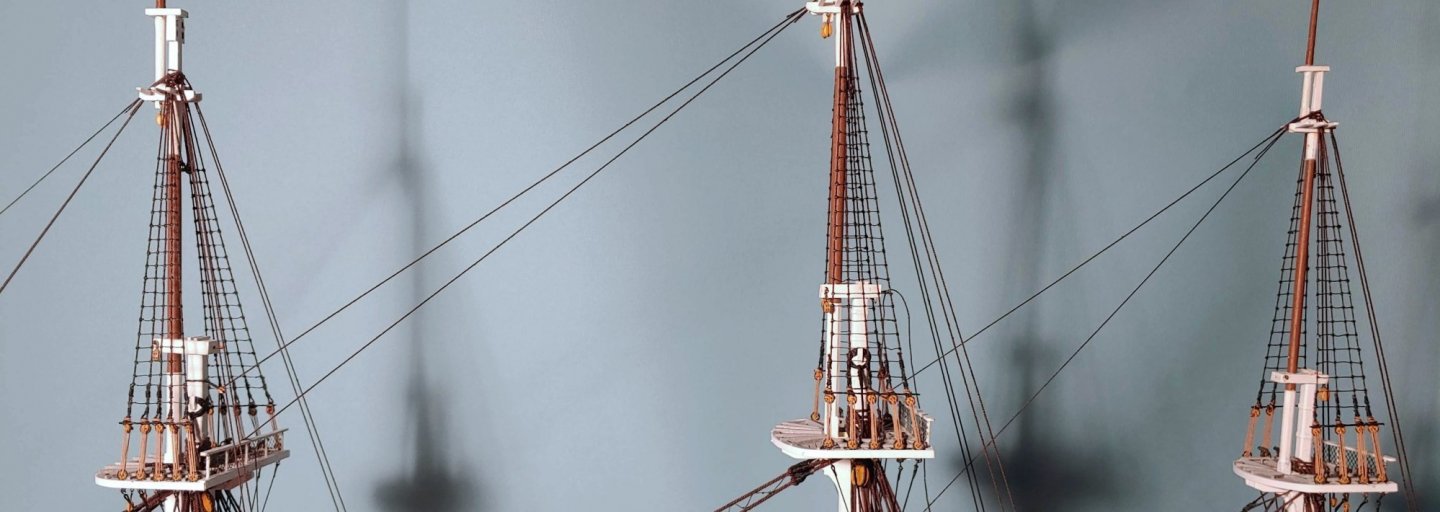
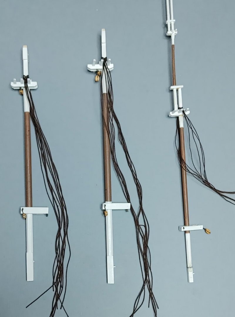
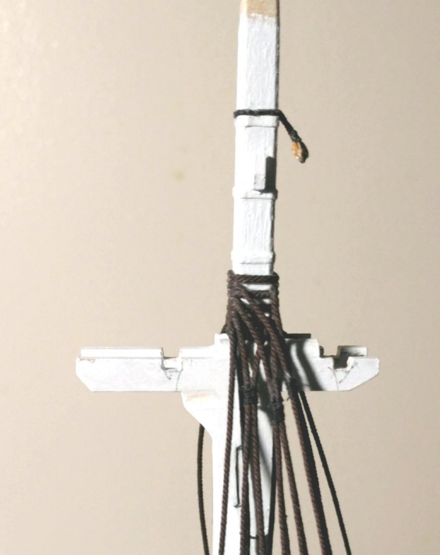
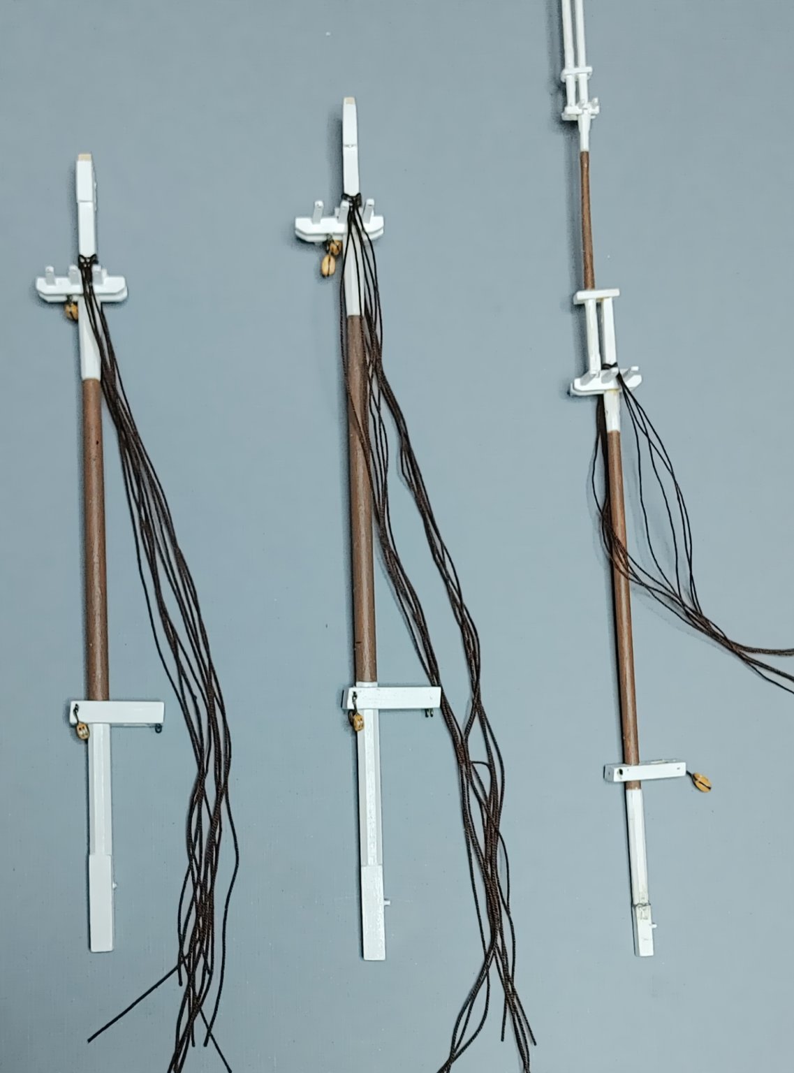
The topmast shrouds and backstays
The topmast heads, like the mast heads, were rigged off model, using the same procedure as before:
The blocks installed under the crosstrees are for jeers. The blocks installed on either side of the mast caps are for lifts. The block installed on the aft end of the mizzen mast cap is for the spanker gaff lifts and halyards, Eyes installed on the under side of the for and main mast caps will have the truss tackles hooked into them.
Here is a shot of the topmast shrouds, fore and aft stays, and backstays in place:

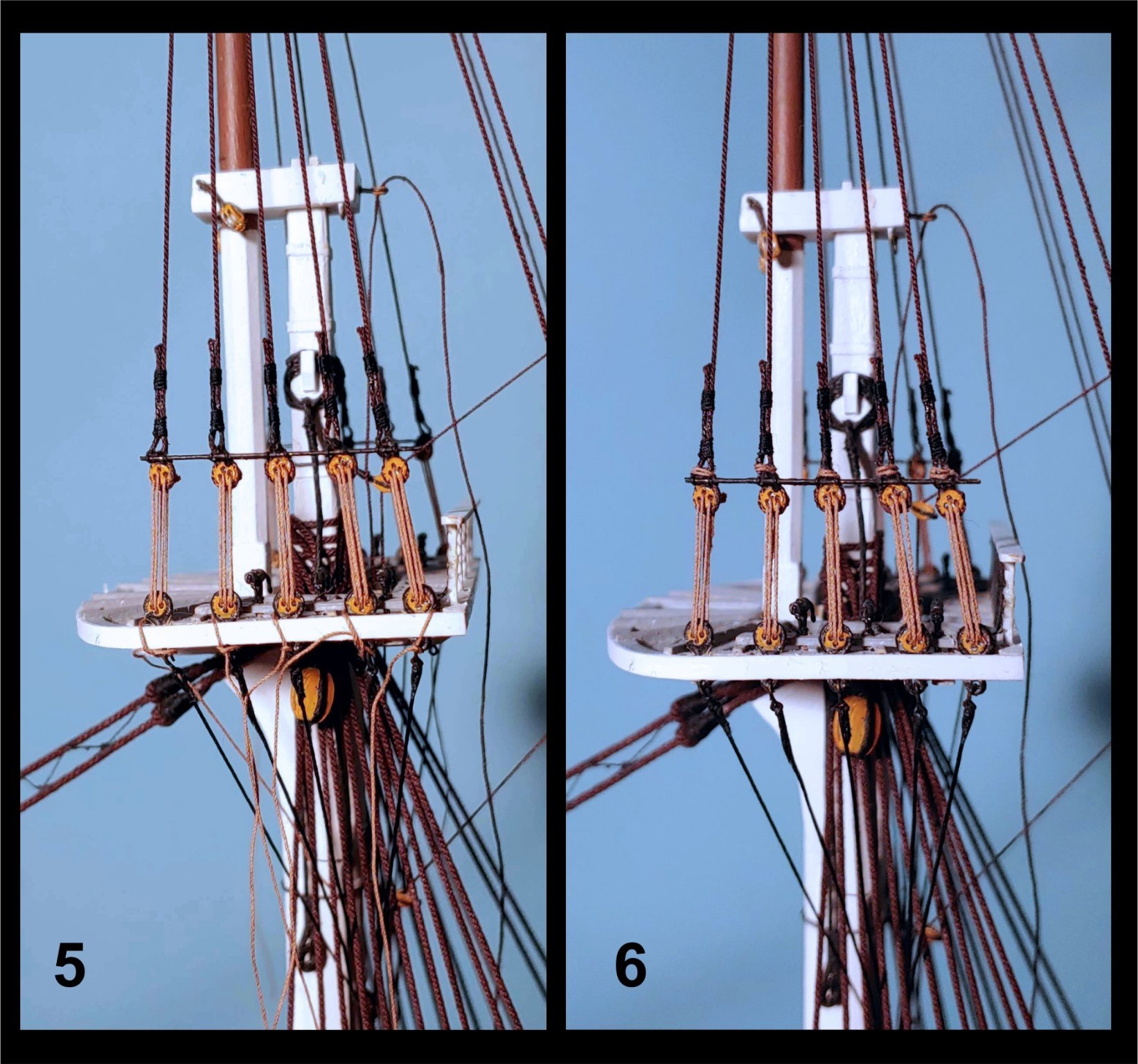
The following composites show the method used for completing the rigging of the topmast shrouds:
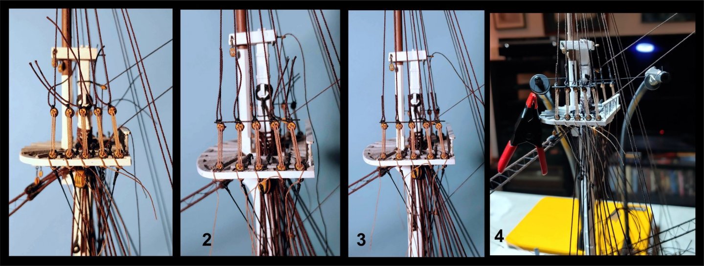

1. Shrouds glued to the deadeyes, the shroud crossing outboard over itself, and the short end on the left side as described in Ben Lankford's book
"How to Build First-Rate Ship Models from Kits" published by Model Shipways - Model Expo. Throat seizings done.
2. Sheer poles installed with their lashings, allowing alignment of the deadeyes.
3. Remaining seizings done.
4. Method of doing the seizings using a clamp and the Quad Hands.
5. Closeup of the seizings and sheer pole. Sheer poles lashings just visible.
6. Thinking that the shrouds were stable, having flexed the mast in every direction without affecting them, I secured the lashings. Months later, when
the weather is colder and dryer, they have gone slack. Hopefully, I can undo the lanyards using de-bonder and tighten them.
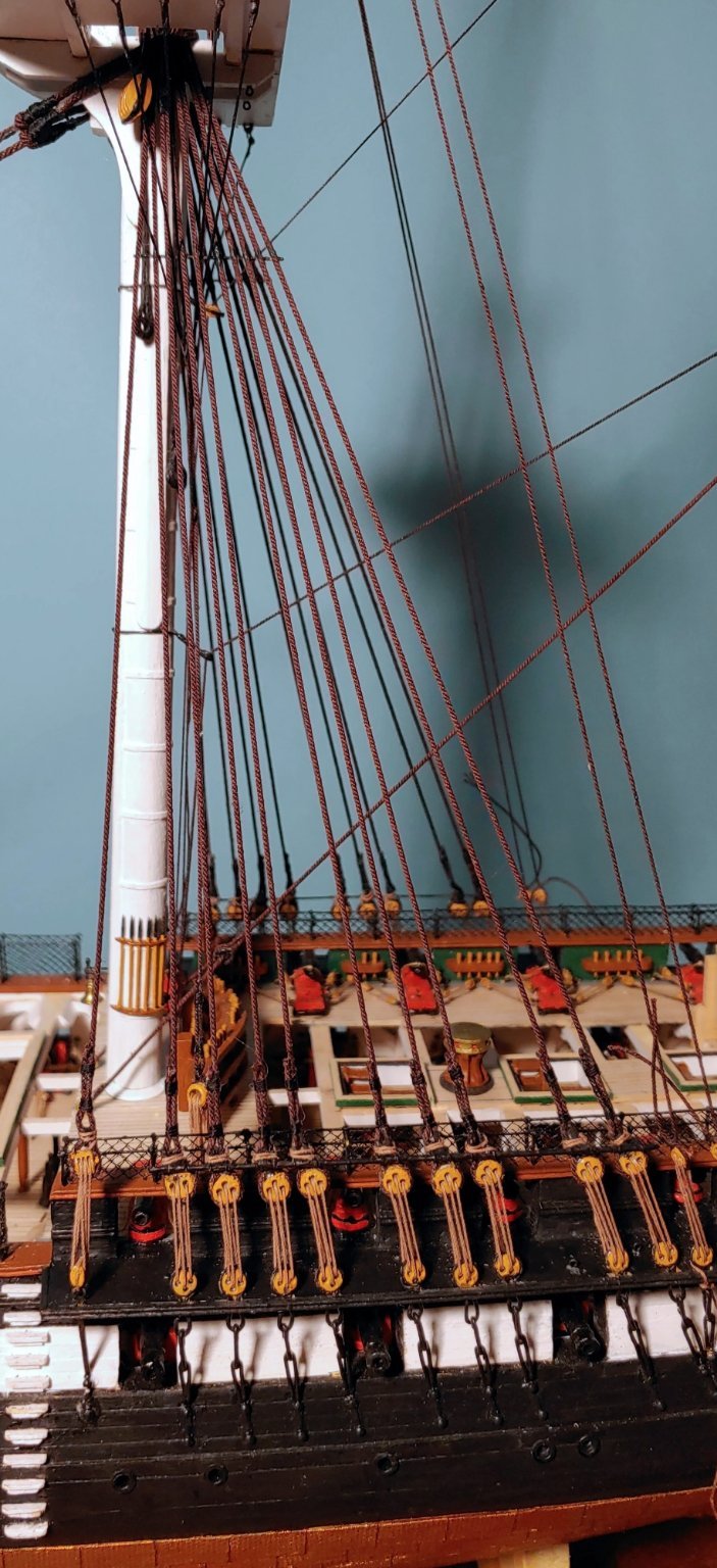
Here is a shot of the main shrouds finalized in the same manner as above:

- GrandpaPhil, BenD, etubino and 3 others
-
6
-
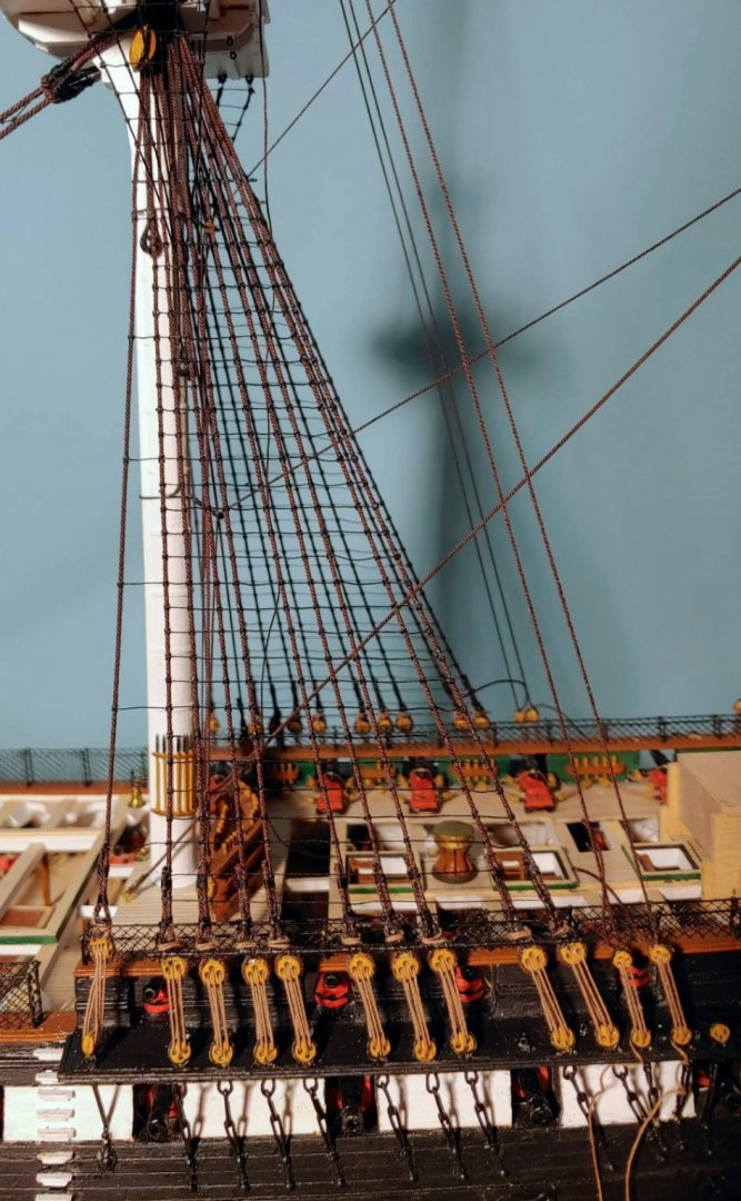
Futtock and bentink shrouds
Here is a shot of the bullseye-lanyard rig for the bentink shrouds:
The following composite shows a closeup of the futtock shrouds, the hooks used to attach them to the top deadeye strops, and a view of the model with these all in place:
-
Rigging the masts
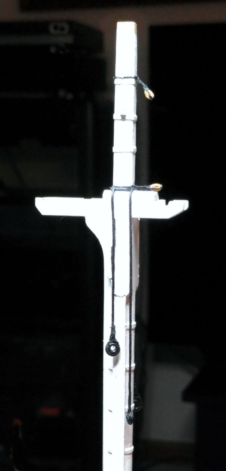
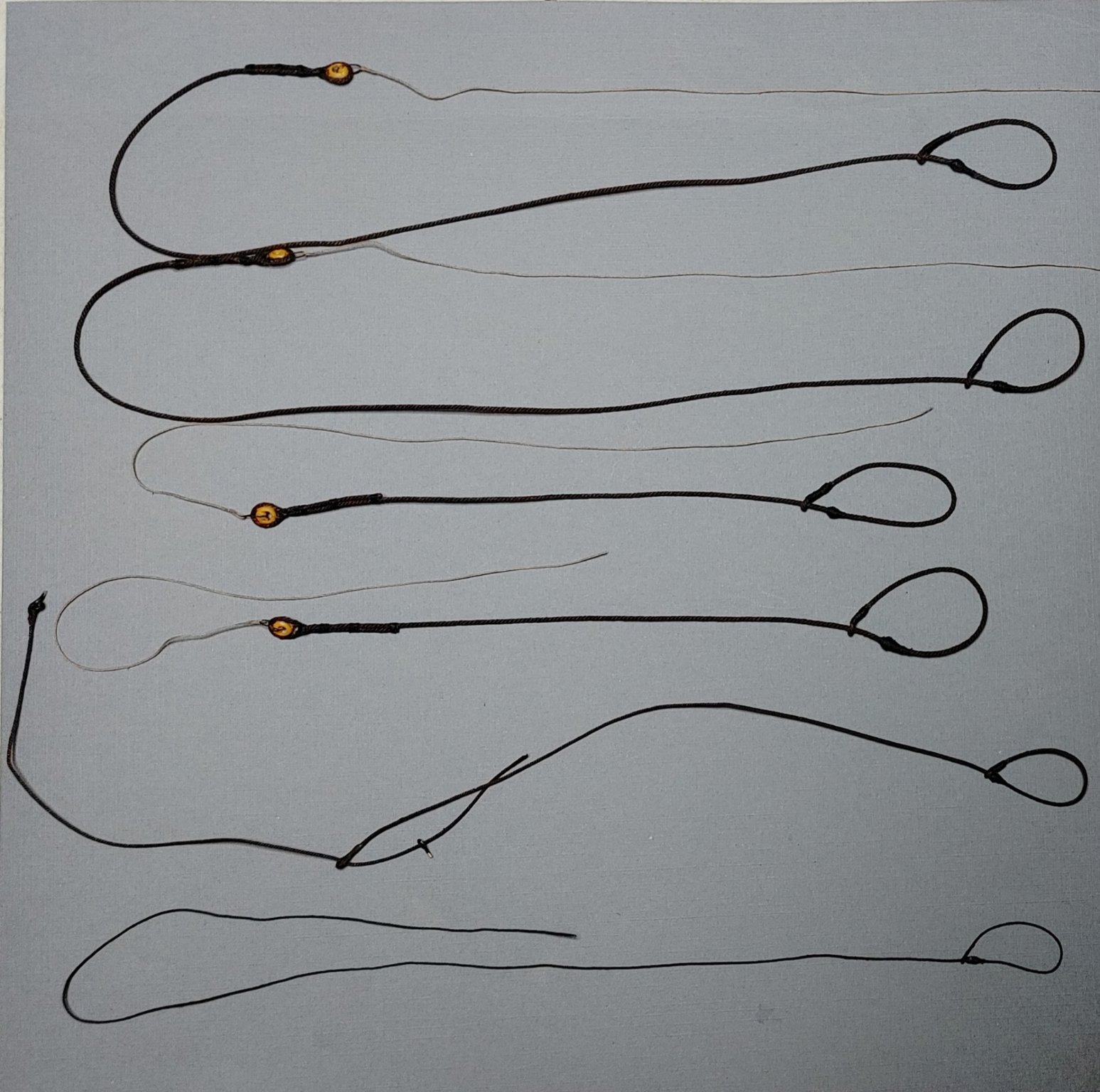
It makes sense to rig the mast heads off the model. First up were the Burton pendants. These were made from BJ rope and BJ metal bullseyes with their centers reamed out to make them look like thimbles as much as possible. I also installed blocks for topmast stays.

Next came the shroud pairs beginning, as prescribed, with the forward starboard pair.
Next up, the jeer pendants.

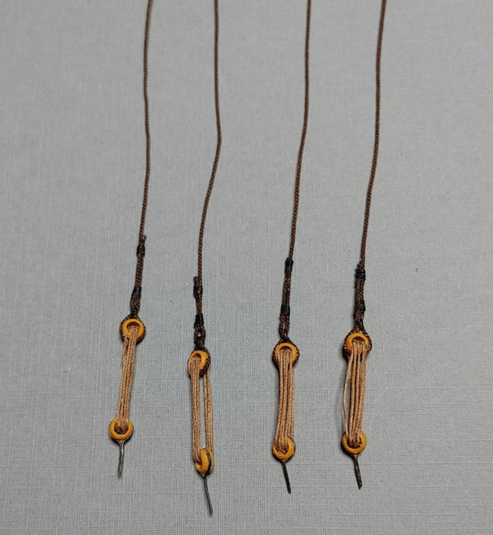
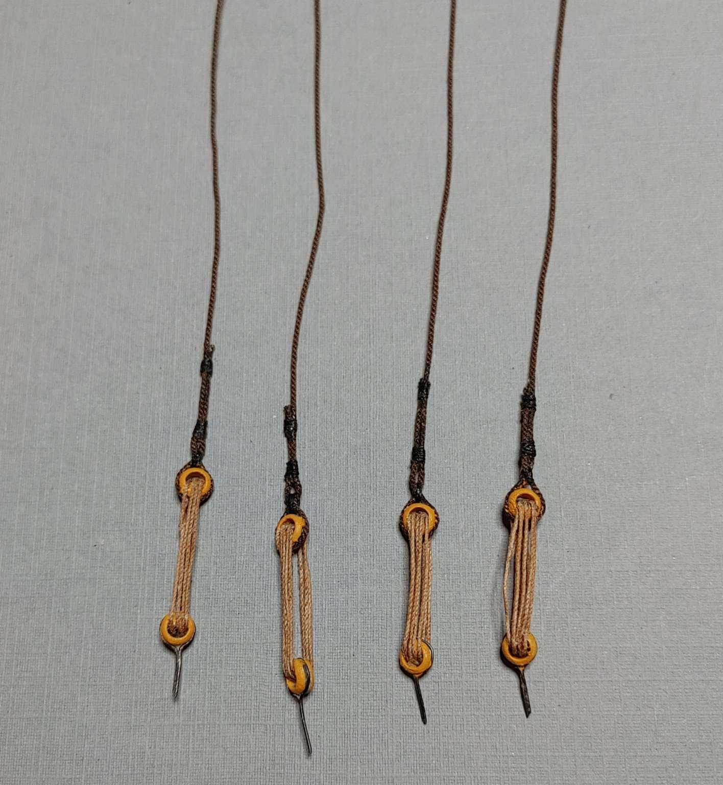
The preparation of the lower mast stays involved making a mouse, which I did by winding .005 line around the stay until I had something that looked like a mouse, the loop which is essentially a fake eye splice, and the bullseye with its lanyard.
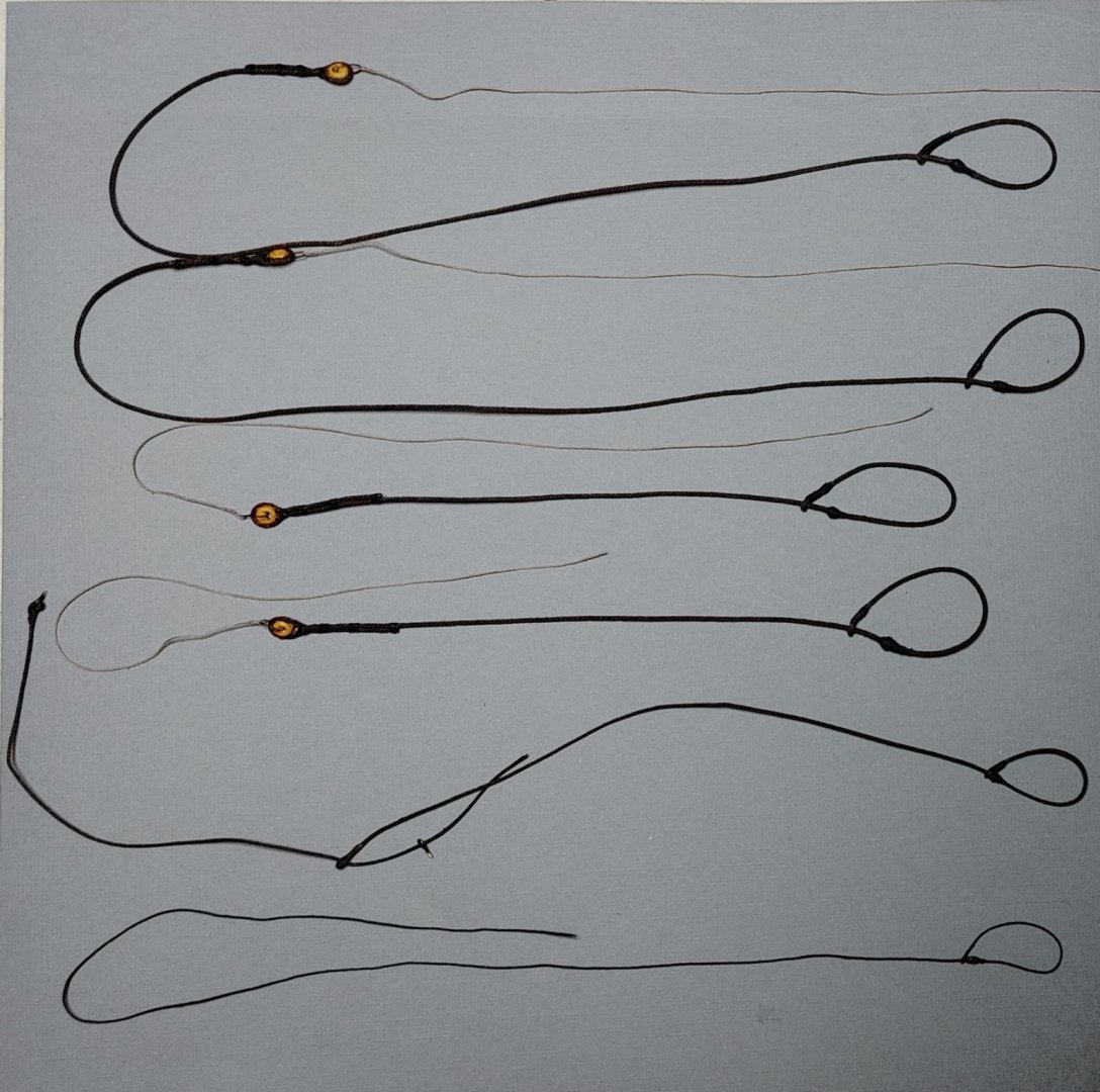
Here the masts are glued in and the stays attached to their respective bullseyes. Ends are left long to allow for future tensioning:
A closeup of the fore and mainstay bullseyes, open hearts and lanyards:

The mizzen stay rig at the deck:
Before attaching the shrouds to their deadeyes, I thought I should get the snaking done. Here is the method I used which is essentially the same as Xken's, with a few departures:
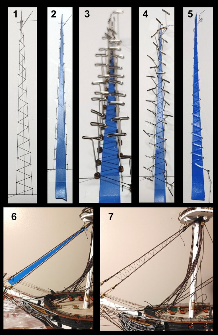
1. The design drawn out on a piece of foamcore. Outer lines represent the stays, the zig-zag line represents the snaking.
2. Masking tape cut to shape and laid down sticky side up, leaving the turns in the zig-zag which will be attached to the stays exposed.
3. T pins passed through metal bullseyes, then inserted into the foamcore at the turning points. Line (BJ .005") having been stretched
and stiffened with diluted PVA threaded around the pins resting on the bullseyes which hold it off the ground so that additional
stiffening using liquid CA may be applied without gluing it permanently to the tape. Gotta be careful not to allow any beading of
the CA to occur on the line.
4. When set, the T pins are removed, the bullseyes are removed, then the T pins are reinserted. The line is then pressed down onto
the sticky tape.
5. An additional identically shaped piece of masking tape laid over the line sticky side down and pressed against the lower tape
capturing the line in between and stabilizing it ready for installation between the stays. This is tricky. if the adhesive on both
pieces of tape is strong enough, removal of the tape in step in step 7 may be impossible. I laid the upper piece of tape down
on a surface and peeled it back off a few times to reduce the strength of the adhesive.
6. Install the assembly between the stays. Most modelers like to tie the snaking to the stay. At this scale, I saw no way to do that
neatly, so I used Elmer's CA.
7. Carefully and slowly peel off the tapes and voila.
Actually I did the mainstay first, but decided to base my post on the forestay which came out better, Practice makes perfect:
Shrouds attached, lanyards rove. Ends left long. I was flying blind as to when to finalize these lines, so I kept my options open as much as I could. Shrouds are glued to the upper deadeyes but not seized:

Looking at the netting rails at the waist, the counter clockwise twist of the hull becomes evident. I chock the fact that I did not catch that at the beginning up to inexperience.
- Bill Morrison, GrandpaPhil, BenD and 2 others
-
5
-
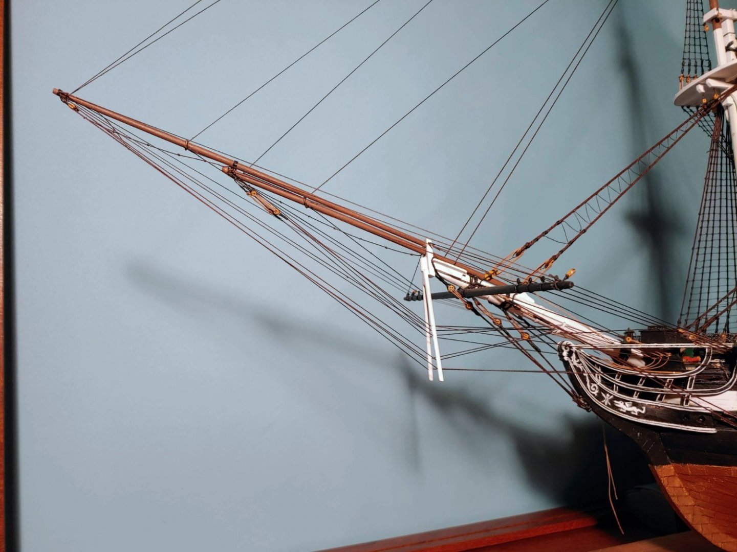
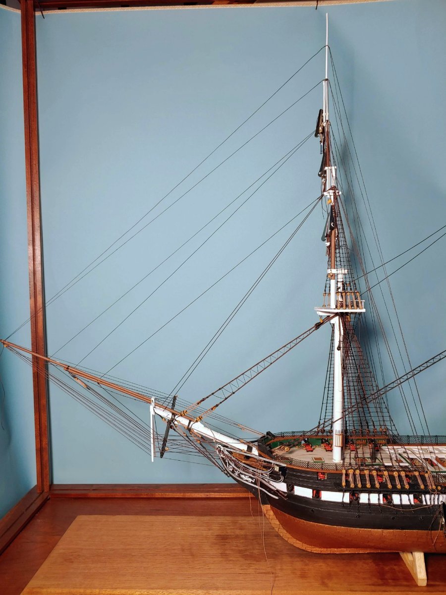
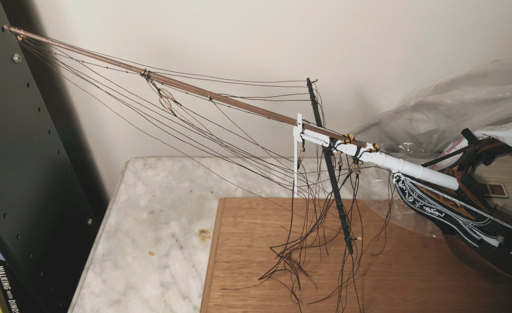
Rigging the bowsprit
This rigging looks more like the present ship, and is less complex than that described in the plans.
I installed the open hearts for the forestay, and set up the bullseyes/lanyards, and deadeyes/lanyards for the bobstays, jib boom martingale guys, and bowsprit shrouds, then temporarily rove them through eyebolts installed on the hull and held them taut with suspended clamps to see how they would look:
Casting all these lines off once more, I then crossed the sprits'l yard and rove the jib boom guys through the sprits'l yard fairleads:

Bullseyes and blocks for the upper stays stropped and painted (left), then installed on the hull (right). Unlike the plans, these are oriented horizontally, so as to leave room for the seats of ease to be reinstalled when the time comes. Blocks installed on the catheads for jib boom guys:
Gammoning and gammoning cleats installed:
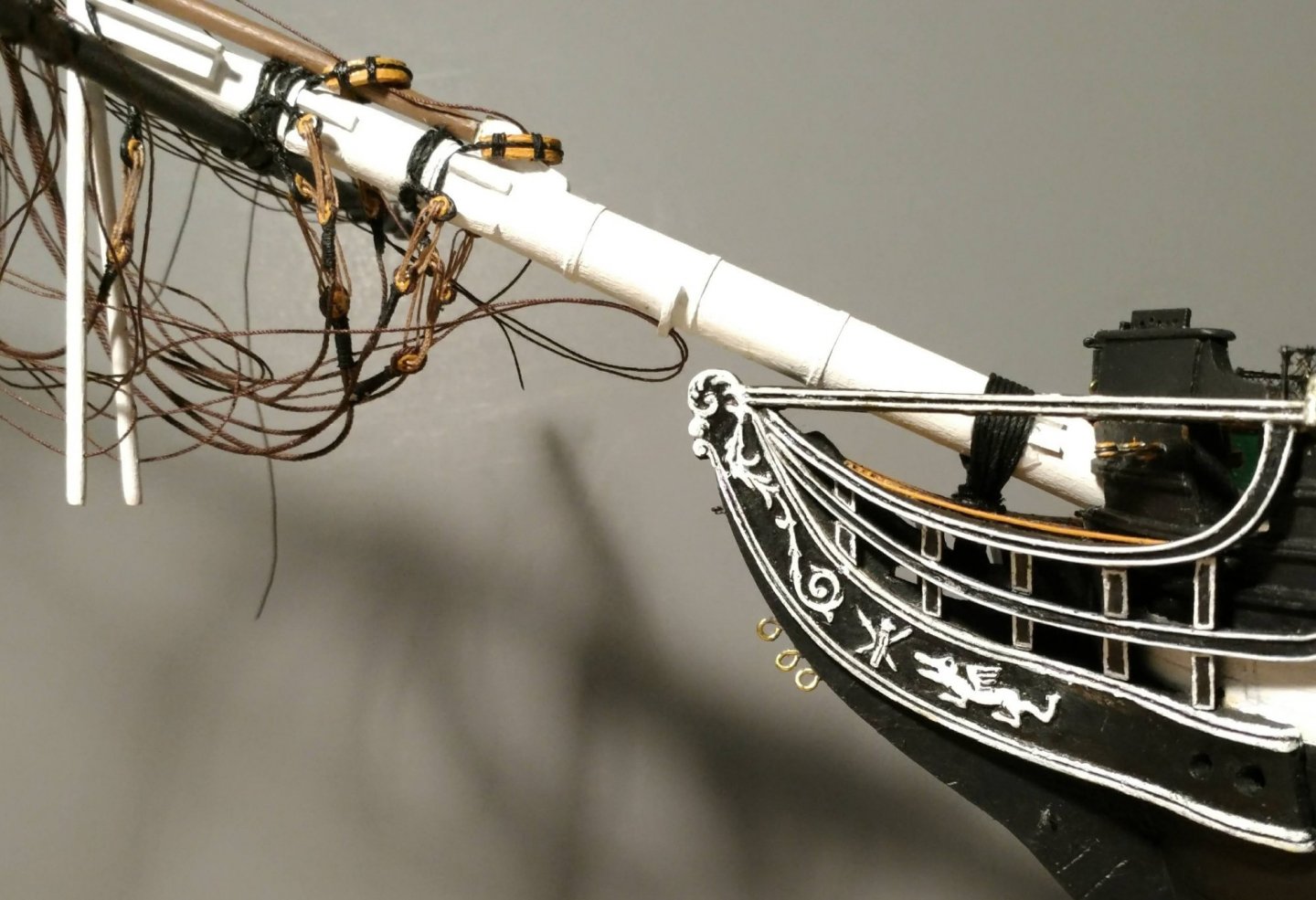
Another view of the gammoning:
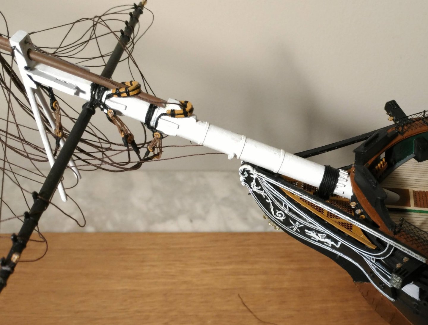
Rigging attached. Glued but not seized, so that if I need to retension them, I can use de-bonder to free them:
Two more views:
- BenD, Ian_Grant, GrandpaPhil and 2 others
-
5
-
Rigging the model
I did rig the plastic models I built as a teen, but it consisted mainly of just tying one end of a line to point A, and the other end to point B, which does not really count as experience. For all intents and purposes, I am a neophyte at this. The posts that follow are intended merely to document my progress. For a real "how to" series of posts, I recommend Xken's MS Constitution build log. It is very methodical, detailed, and thorough. I did not attempt any serving, parceling, puddening, or worming in this build. The kit includes a wide variety of ropes of every size you would need. It comes in two colors, black and white. I did not like the white because it does not look like rope, and I was disinclined to dye it all. For the rigging of the masts and spars, I am using Syren dark brown, light tan, and dark tan rope which is as good as it gets and looks just like rope.
For seizings, I am using BJ .005 black line. The appearance of the larger sizes of BJ.s black rope is smooth and shiny which to me has a "served" look. I am using this for things like pendants, trusses, etc. I use BJ's black annealed steel wire for stropping blocks. It looks neat, and is easy to form into hooks when desired. I use PVA glue when securing ropes to wood, but I use Elmer's CA when stropping the metal blocks as I described above in my discussion of the carronade rigging. I could not get diluted PVA to hold seizings, so I use CA for that too, applying it to the underside of of horizontal seizings and the inboard side of vertical seizings to minimize visibility of shiny spots. I also apply black paint with a fine brush as needed. Many modelers will be aghast at this, but I have also heard from some other experienced modelers who have been using CA for rigging for years and have had no problem. Time will tell.
-
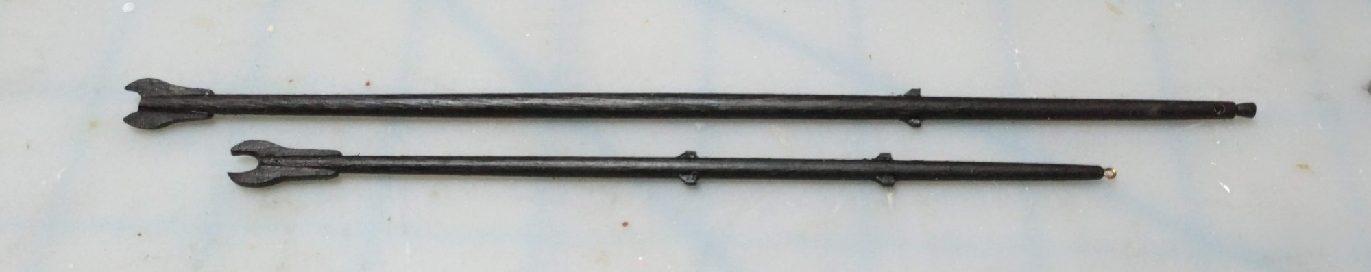
The spars
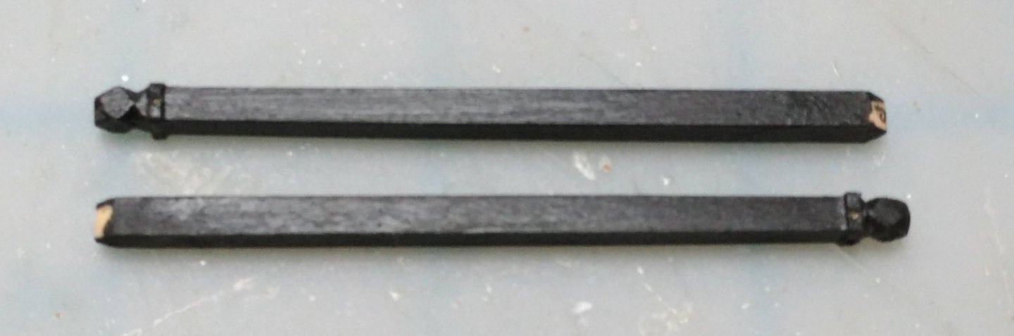
As I did with the topmasts, I elected to make the course and topsail yards from square stock.
I painted the square stock black so that I could keep track of which facets were the result of imperfect planing, and which were from more perfect milling at the factory. The latter would then bear the sling cleats, the back fishes, and the top and bottom chafing battens, and the former would bear only the diagonal chafing battens. Perhaps someday, I will be able to make all facets equally true. Battens and stop cleats were made from 1/32" basswood while the sling cleats were built up in much the same way as the jeer cleats were on the lower mast heads. Tapering was done by hand, as the double ended taper precluded using a drill. Rolling the yard across the table under my fingers confirmed symmetry.
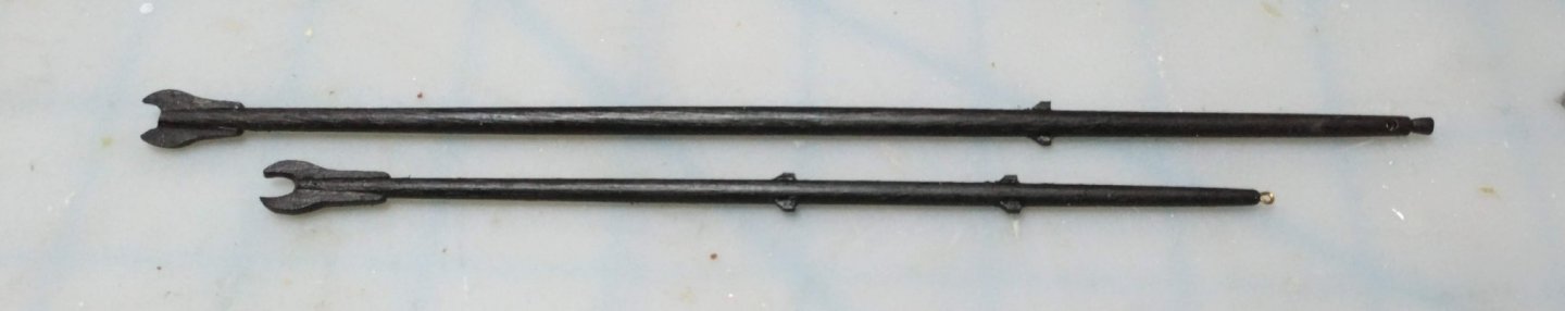
The t'gallant and royal yards were made from dowel, as there are no octagonal sections on these. 1/64" plywood was used to make the stop cleats on these. I may yet install bits of brass rod into the ends of the lower yards to which to seize the flemish horses.
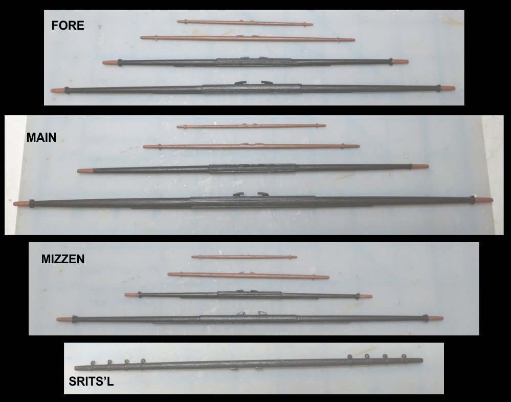
The Sprits'l fairleads are metal bullseyes with the centers reamed out and stropped with annealed steel wire (34 gauge, .010" BJ #902) which was inserted into holes in the yard. Wire was then glued around the yard to make it look like it was all one piece.
Since this was done, the mizzen t'gallant yard up and disappeared on me, so I will have to make another. Fittings to be attached when all standing rigging is done, and before running rigging begins.
Spanker gaff and boom:
I made up the foretack boomkins which will be installed when all other lines at the bow have been rigged.
This concludes the wood work for the model.
- mort stoll, Bill Morrison, BenD and 1 other
-
4
-
The t'gallant masts, royal masts and sky pole
As I did not have confidence in my ability to render these neatly, I took these parts from the Revell model. They are more flexible which means that rigging theirs stays will be tricky. It also means that if they accidentally encounter something, they will not snap off.
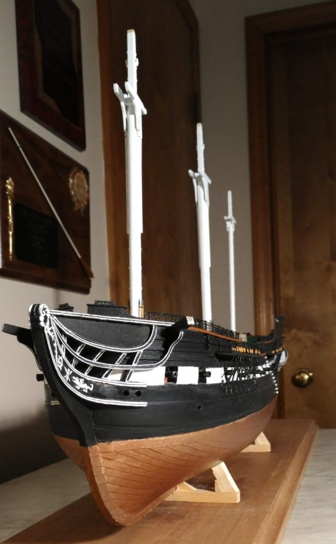
Here is the entire mast assembly with these parts fry fitted:
Completed masts fitted on the model:

- WalrusGuy, etubino, GrandpaPhil and 2 others
-
5
-
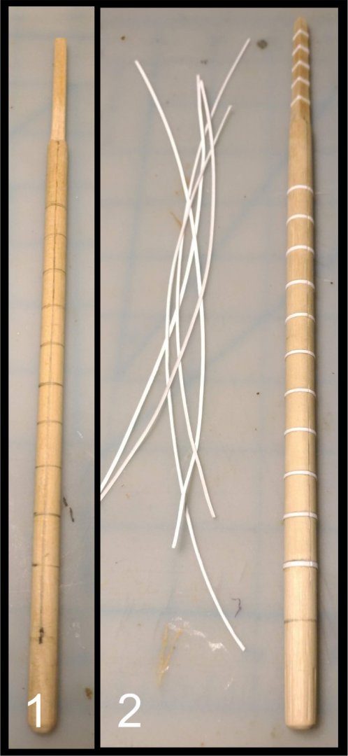
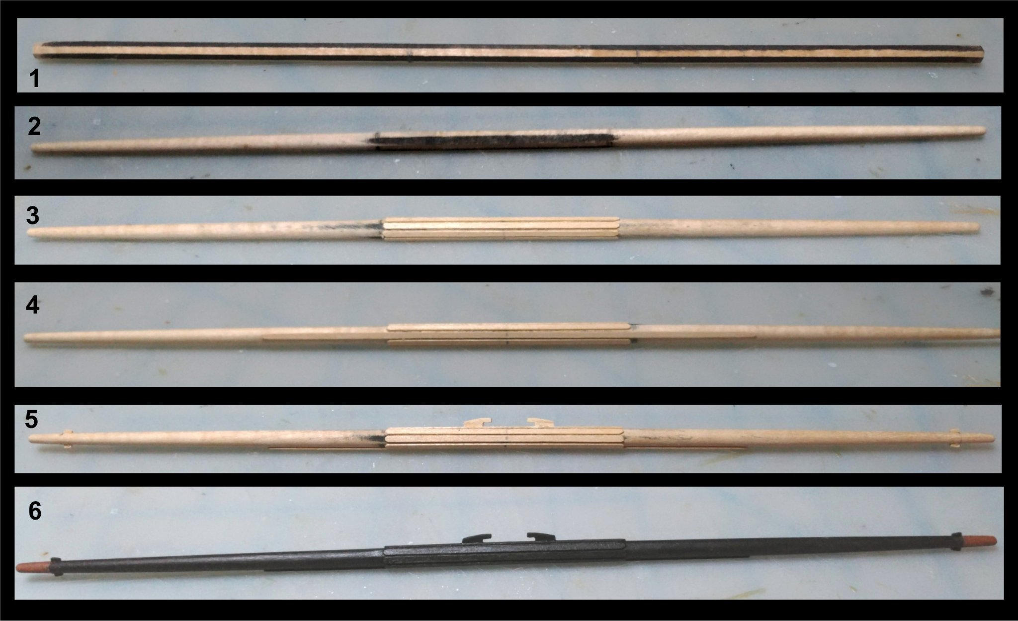
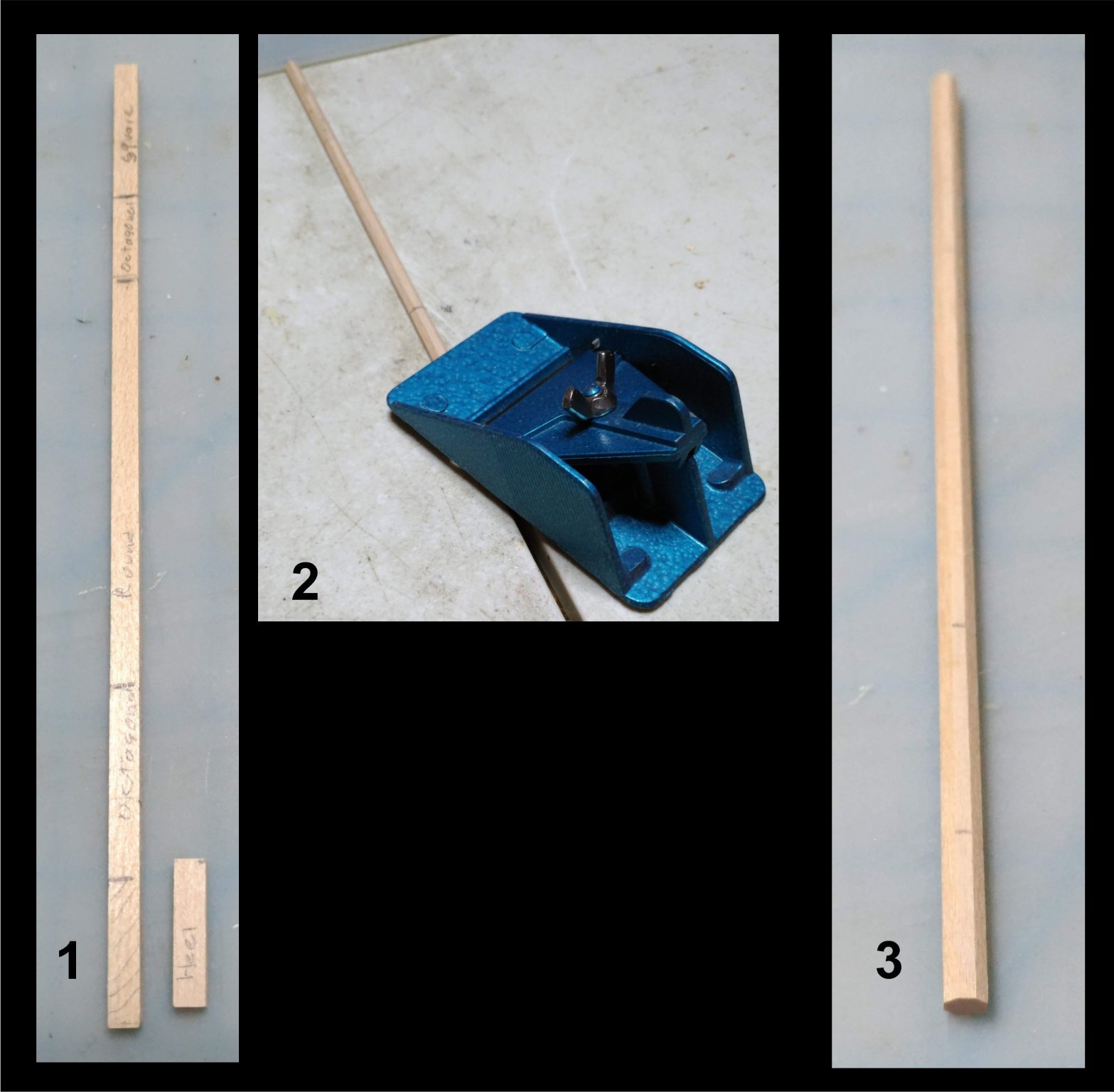
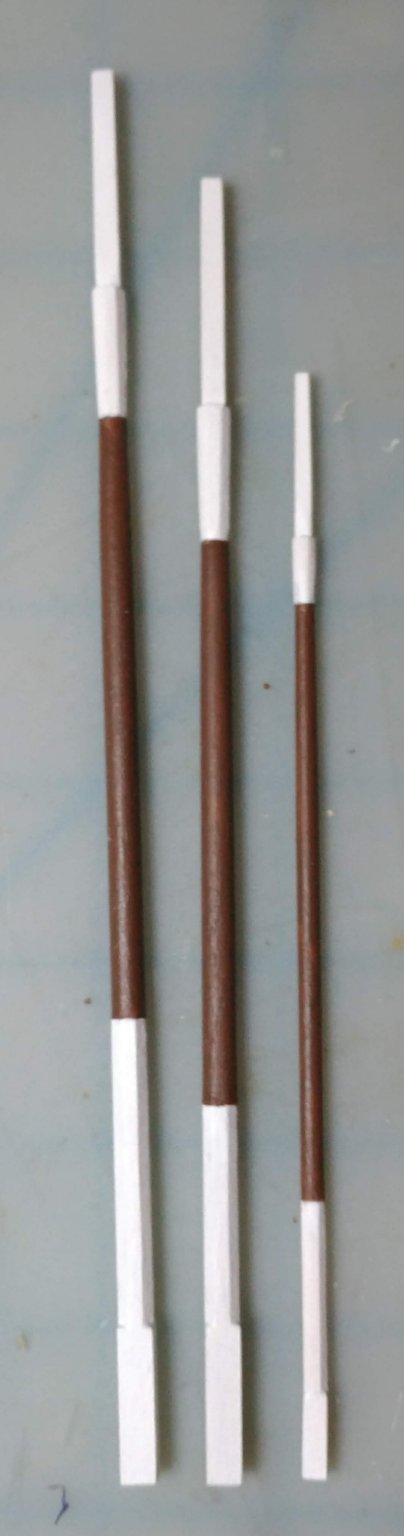
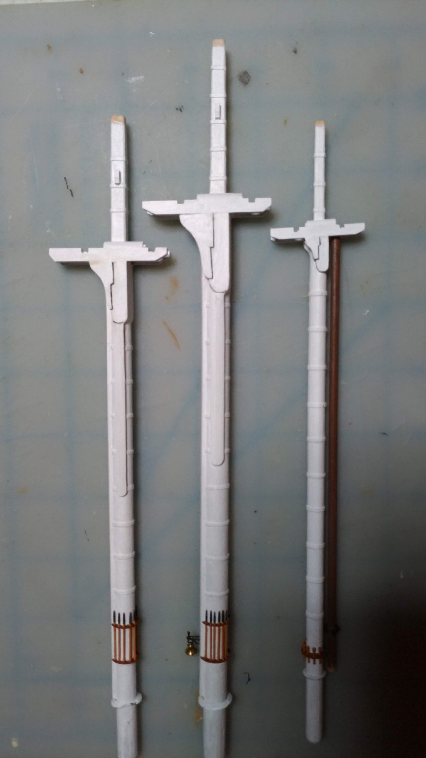
The topmasts
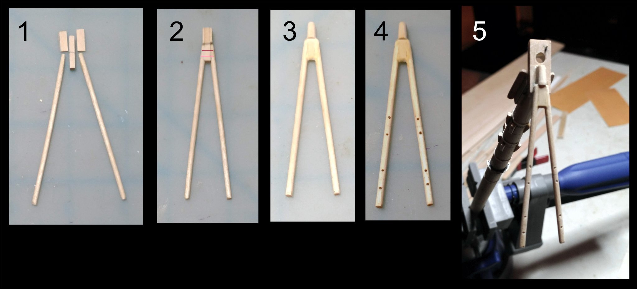
The bottom of the topmasts are square. Above that they are octagonal, then round, then octagonal, then square. Rather than file sections square, build up with pieces, file octagonal, etc. I decided to start with square stock.
Here is how I proceeded:
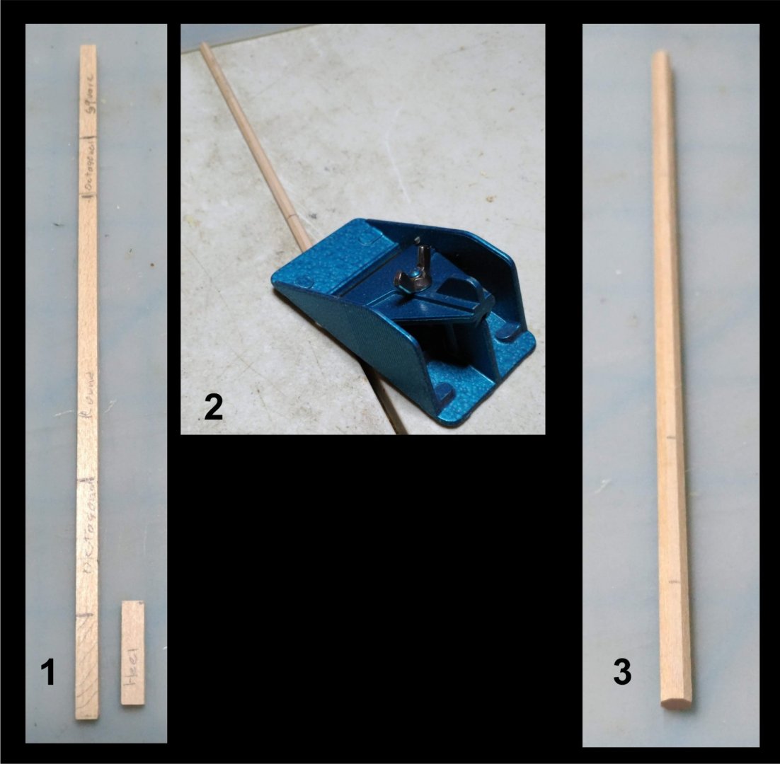
1. Start with a piece of square stock. Mark out the sections. Square heel is a separate piece
2, 3. Plane it to an octagonal.
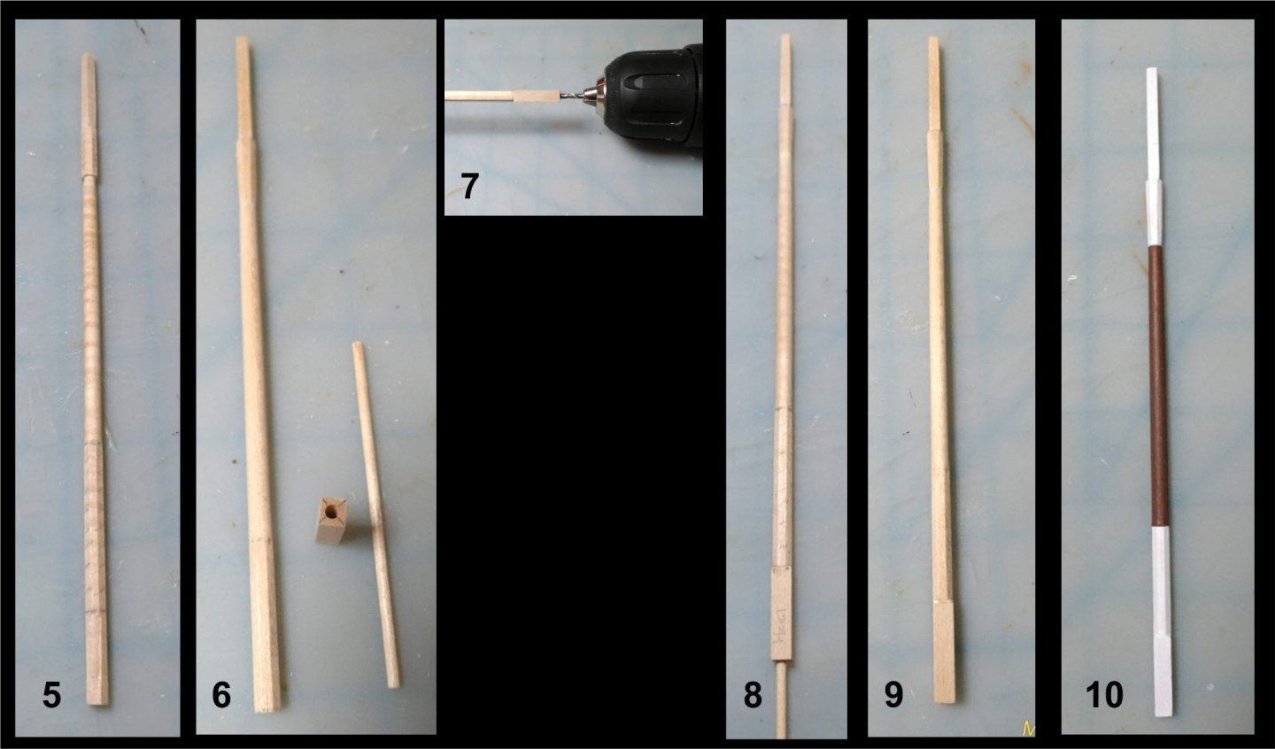
5. Sand the middle section round and taper it. This was done by hand. I do not have lathe. Taper the hounds with a chisel and square the top with a file.
6. Using a drill press drill a 1/16" hole straight through the heel.
7. Glue the heel to the bottom of the mast, and, using the hole in the heel as a guide, drill into the mast itself.
8. Insert the dowel through the heel and into the mast and glue, reinforcing the joint.
9. Finished topmast.
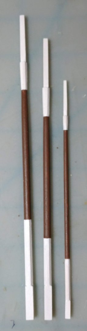
10. Topmast painted.
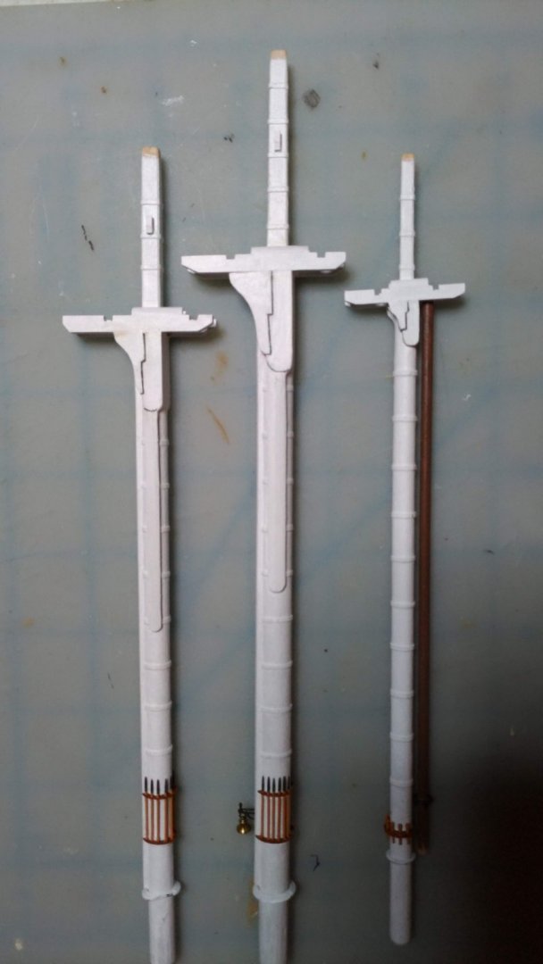
The three topmasts finished and painted:
The topmasts dry fitted:

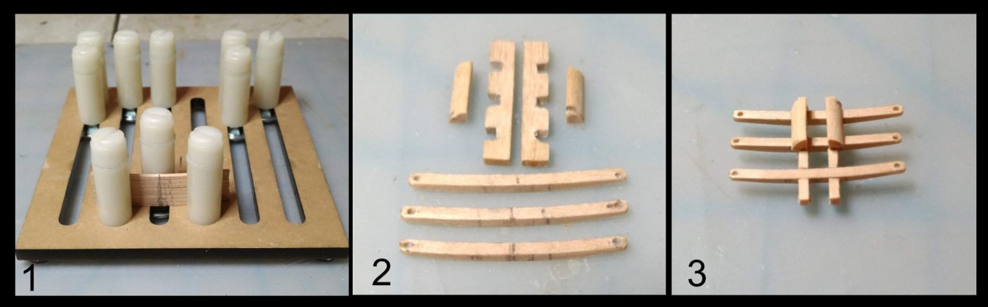
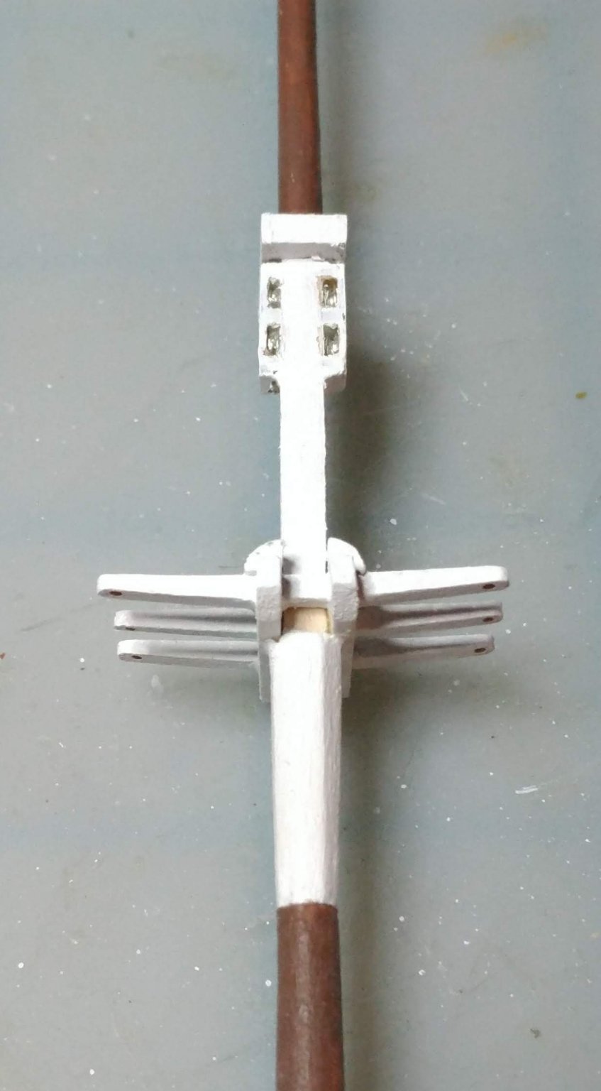
I used two methods to make up the cross trees. In the first, I notched the trestle trees to receive the cross trees. In the second I used a composite "built up" approach: more involved, but neater. The bolsters were cut from 1/4 round stock provided in the kit.

Cheek blocks were added to the topmast heads:

Topmasts with cross trees dry fitted to the model:
-
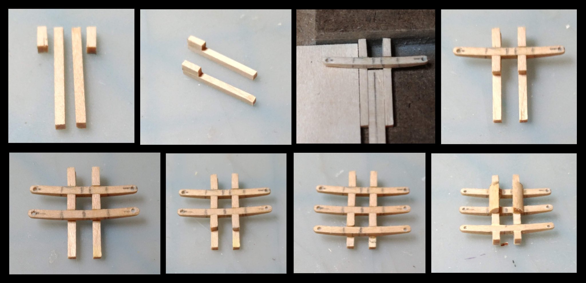
The fighting tops
The fighting tops are scratch in this kit. Drawings and plans are given in the instruction manual and in the plan sheets.
Heads up: The mizzen top plan in the plan sheet is asymmetrical.
I also looked at the plans in the Marquardt AOS, and the tops in the Revell model.
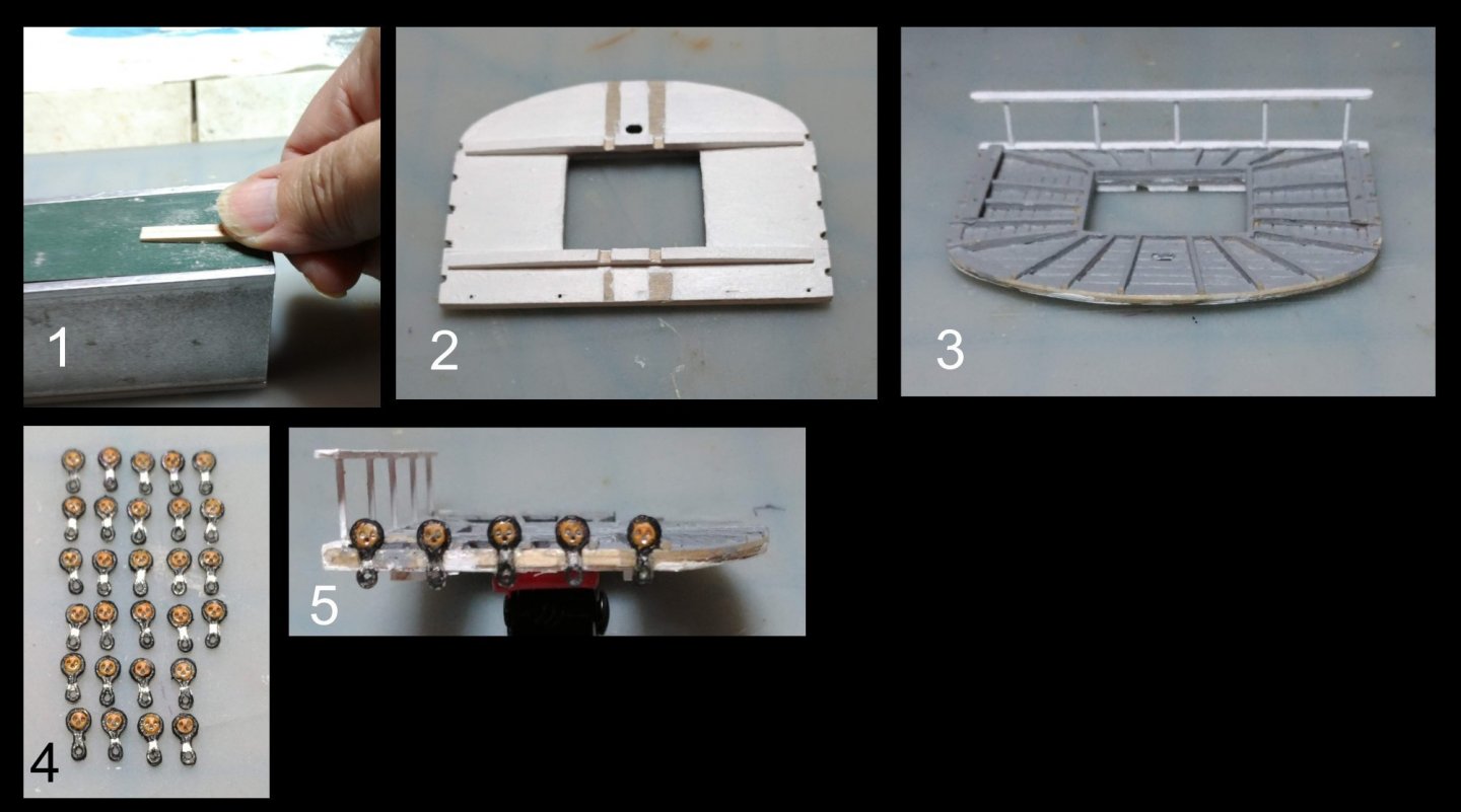
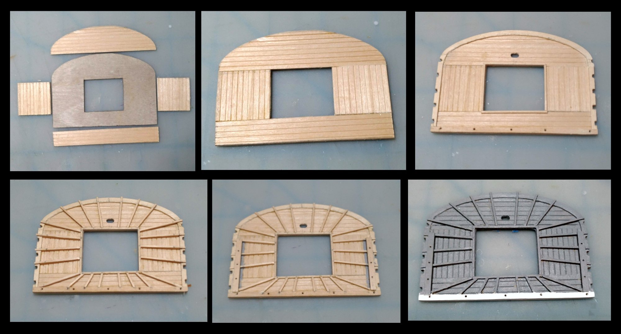
The upper surface of the top should be painted gray, so I used scribed decking to show planking detail. I used 1/64" birch plywood to stiffen the structure. The rim and the battens bordering the lubber hole were of 1/32" basswood stock, giving a total of 3/32" thickness.
The problem with this arrangement was that the backing and decking tended to curl upwards in a direction perpendicular to the grain of the first and third layer of the plywood. Clamping it into a vise as the glue dried helped. Floor battens were of 1/32" by 1/16" stock. They taper from a 1/16" height at the outer rim to 1/32" to match the batten which borders the lubber hole. Notches were cut to receive the stropped deadeyes.
Here is a composite illustrating this:

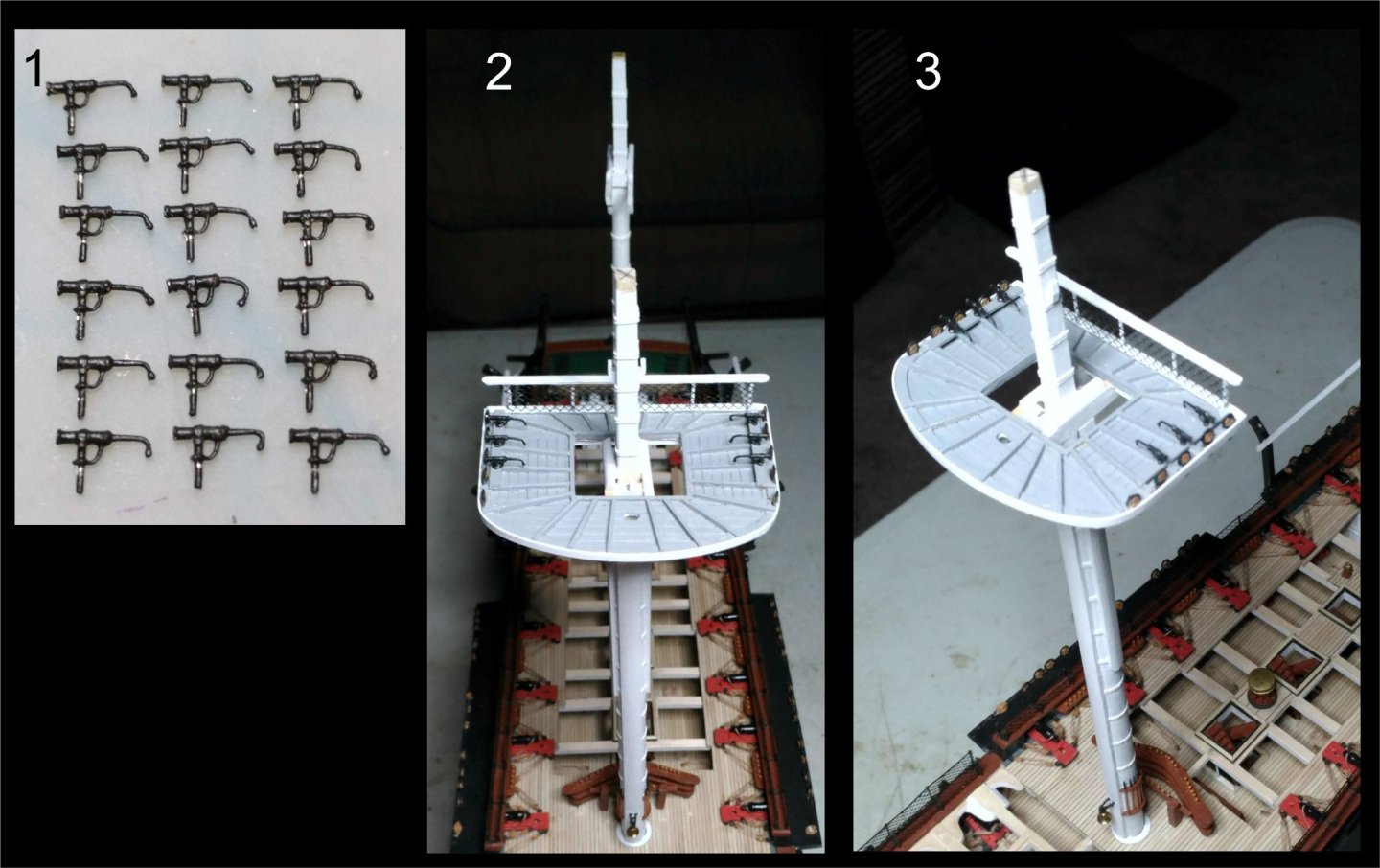
Battens added to the sides will house the swivel guns. The 1/16" thick batten on the aft border will support the rear rail assembly.
In the next composite, photo 1 shows one the crosstrees being tapered. The rest, I believe is self explanatory.
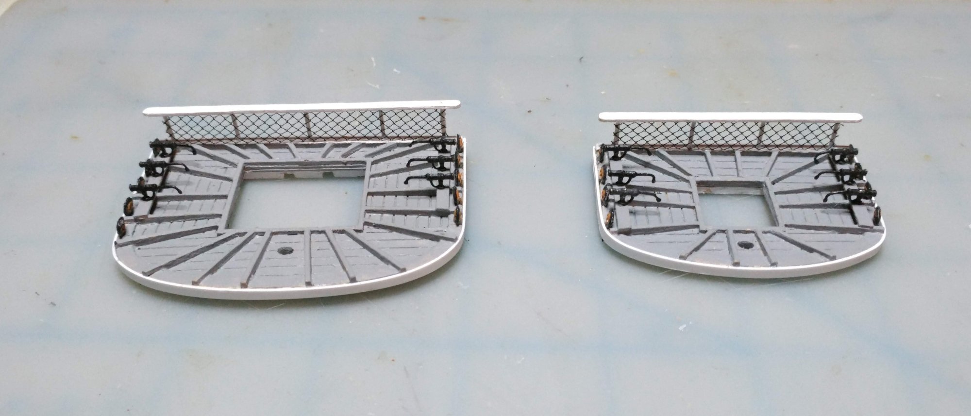
The next composite shows the cast swivel guns, and the finished top dry fitted to the mast with its outer rim of stryrene, and the aft rail netting (same as the hammock netting) installed:
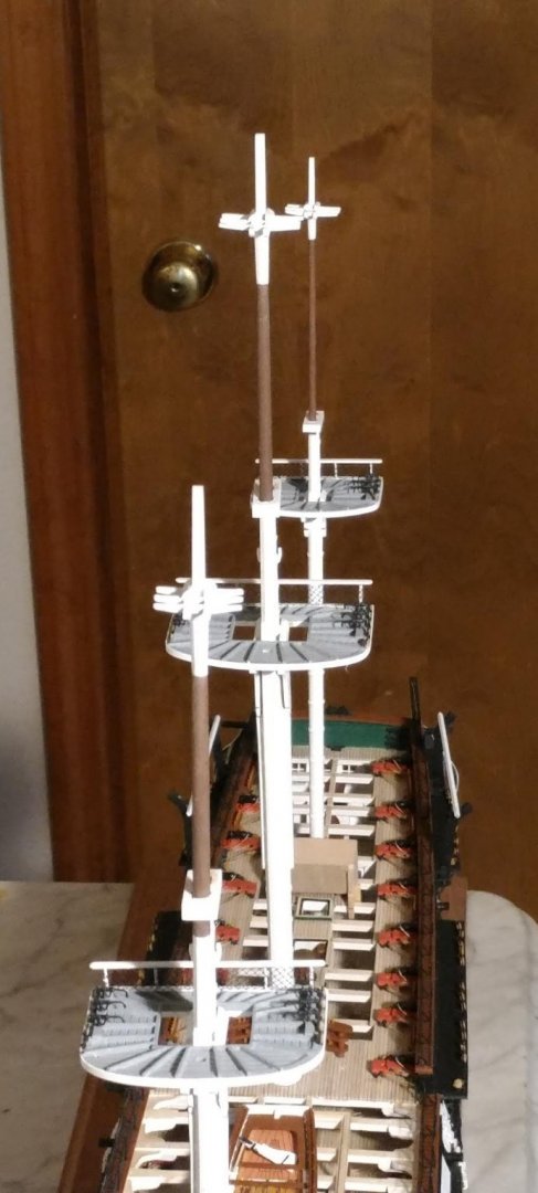
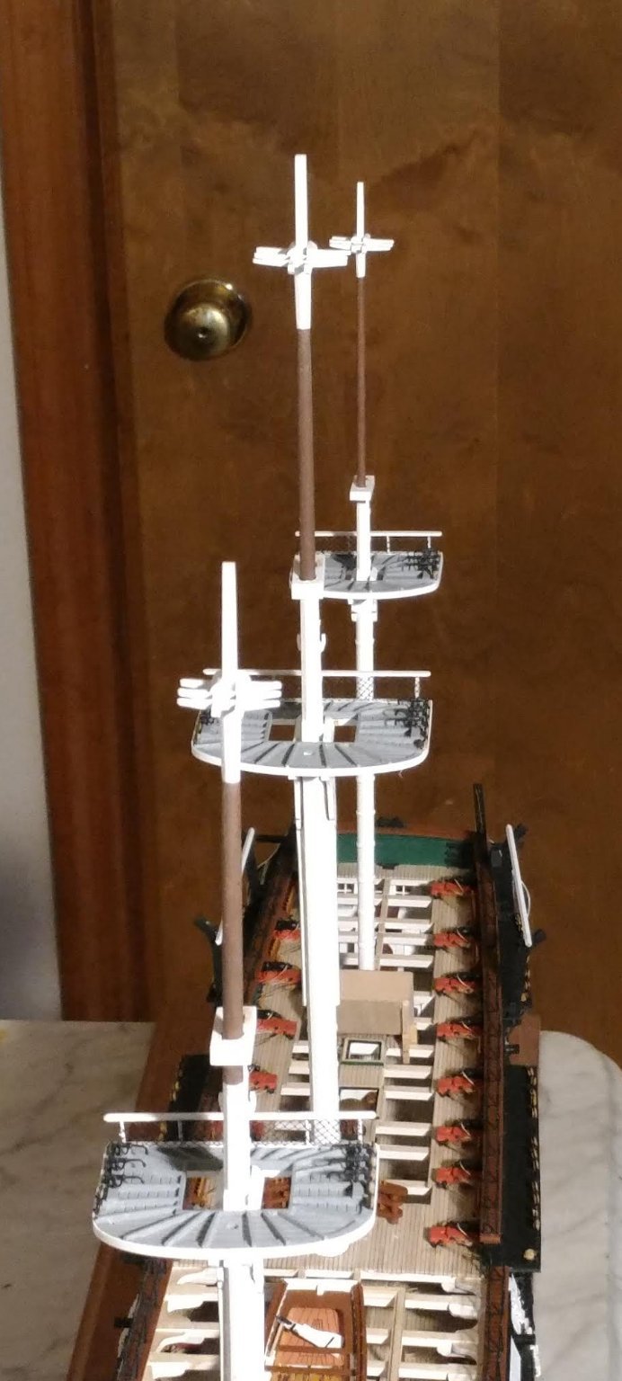
A view of the finished fore and mizzen tops:
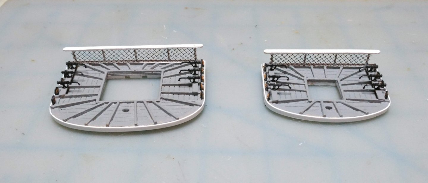
All three tops dry fitted:
-
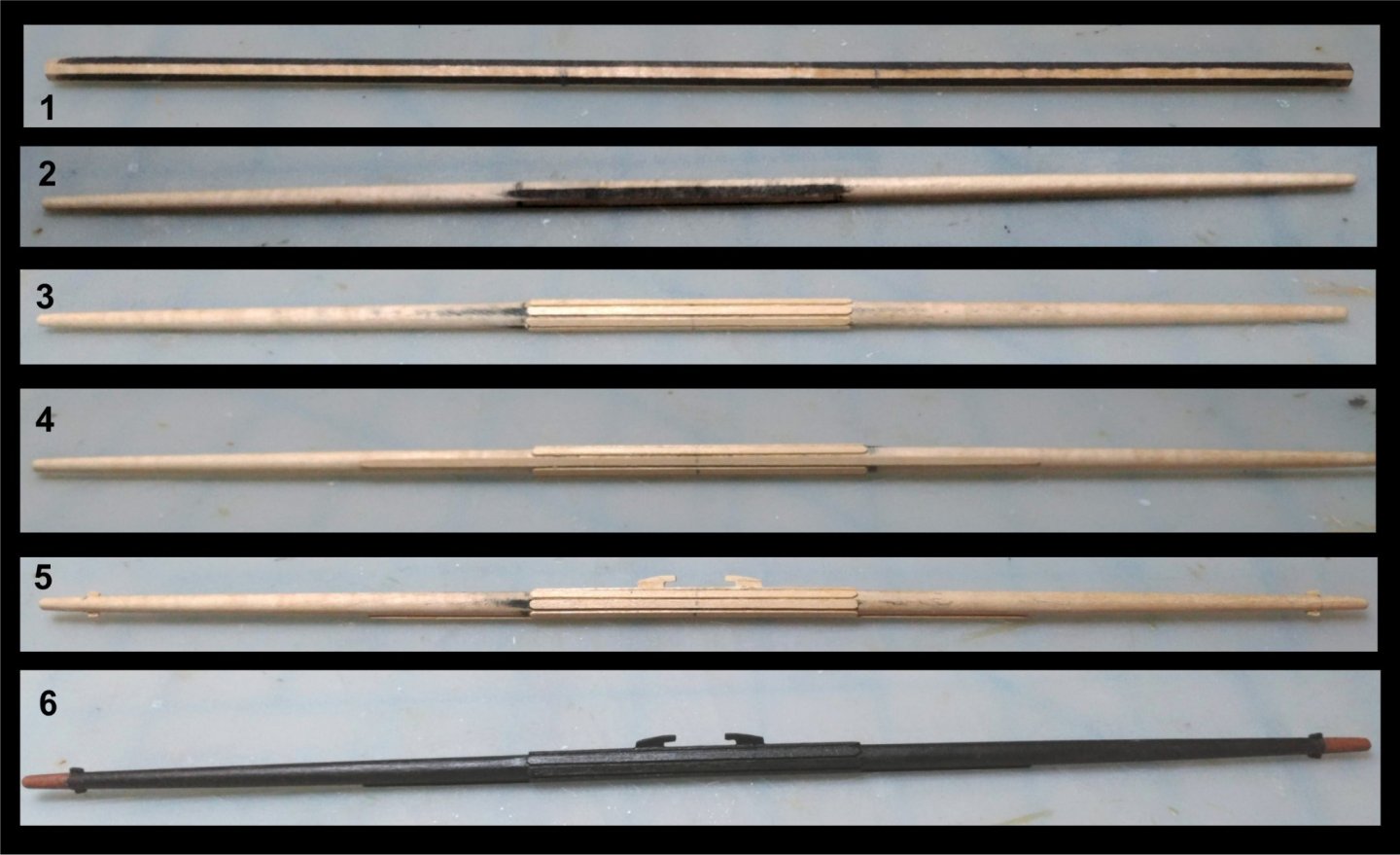
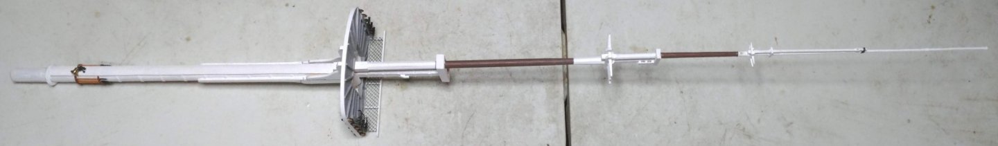
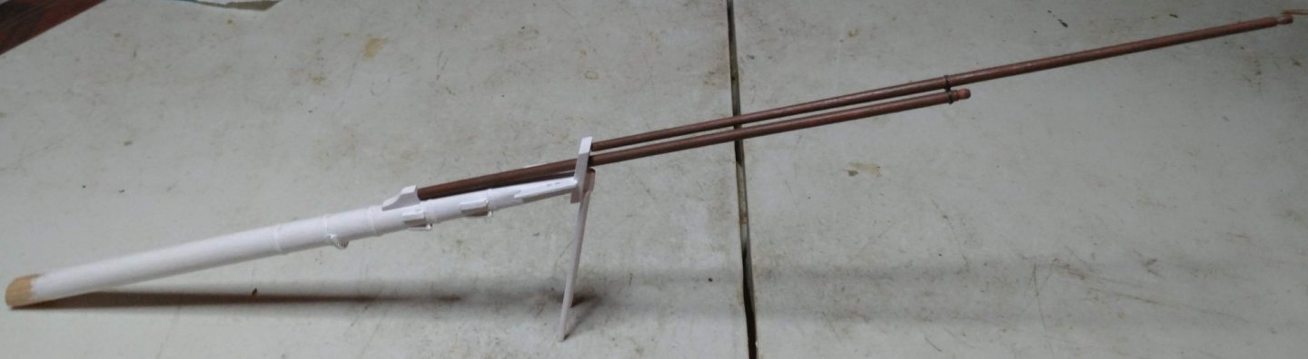
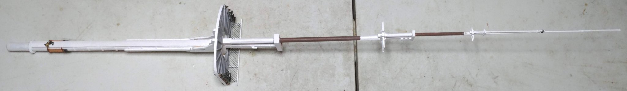
The Bowsprit and jib booms
The bowsprit was made from 3/4" birch dowel. The hoops were made from 67 lb card stock as in the masts.
Here is a composite illustration of the construction sequence:
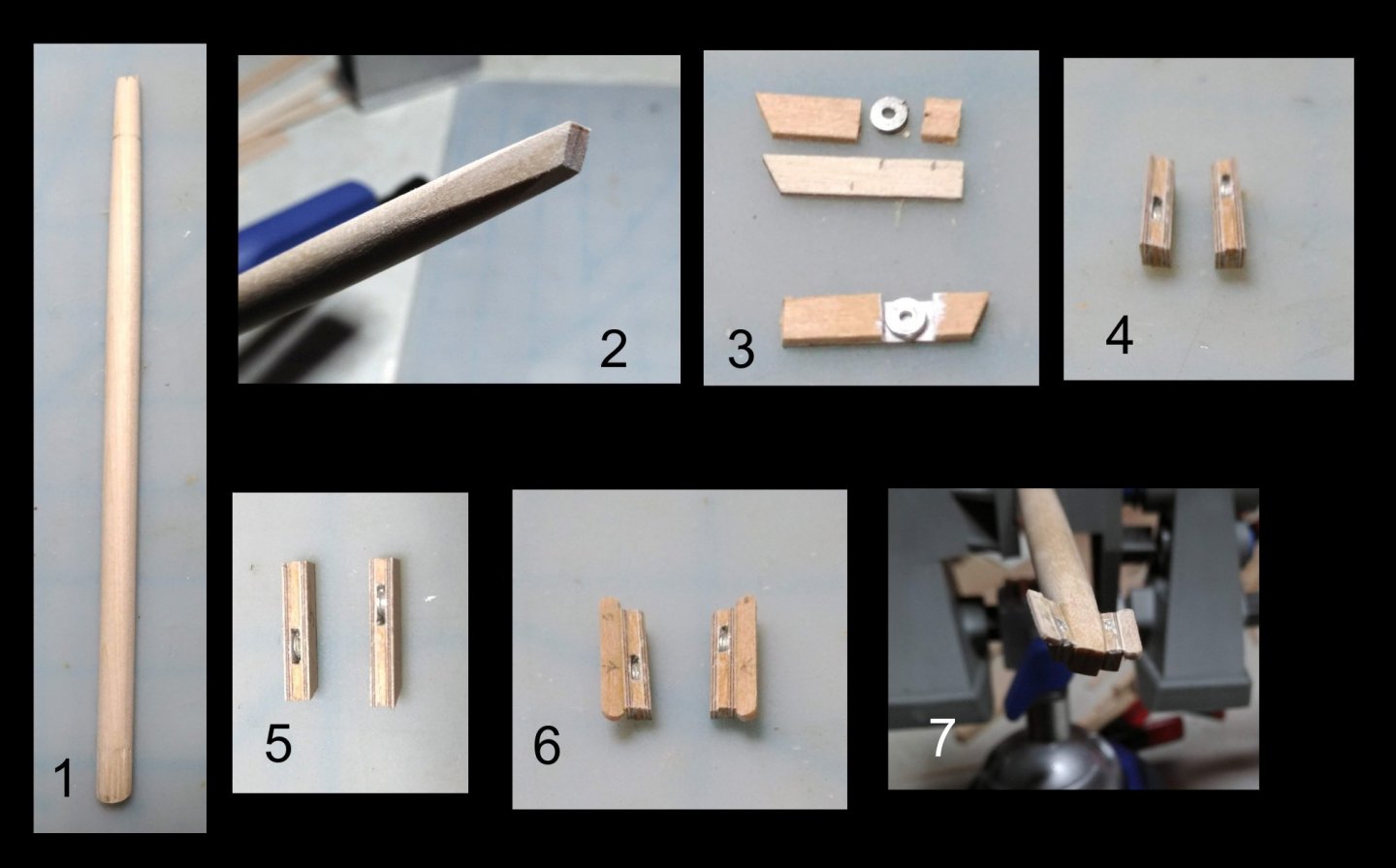
1. The bowsprit tapered using the same method as in the masts.
2. Flat sections sanded in using the disc sander.
3. Top - components of the bee block: two 1/32" strip of basswood, 2 strips of 1/32" birch plywood ( If I had it to do over, the outboard layer would be 1/64" plywood.), and a cast metal sheave from BJ, sanded to a 1/32" thickness
Bottom: two layers assembled.
4, 5. Bee blocks assembled. Upper surface beveled to get the proper angle.
6. Completed bees. Inboard edge of the Outboard wing component beveled to compliment the angle of the upper edge of the bee blocks.
7. Bees glued onto flat sections of the bowsprit.
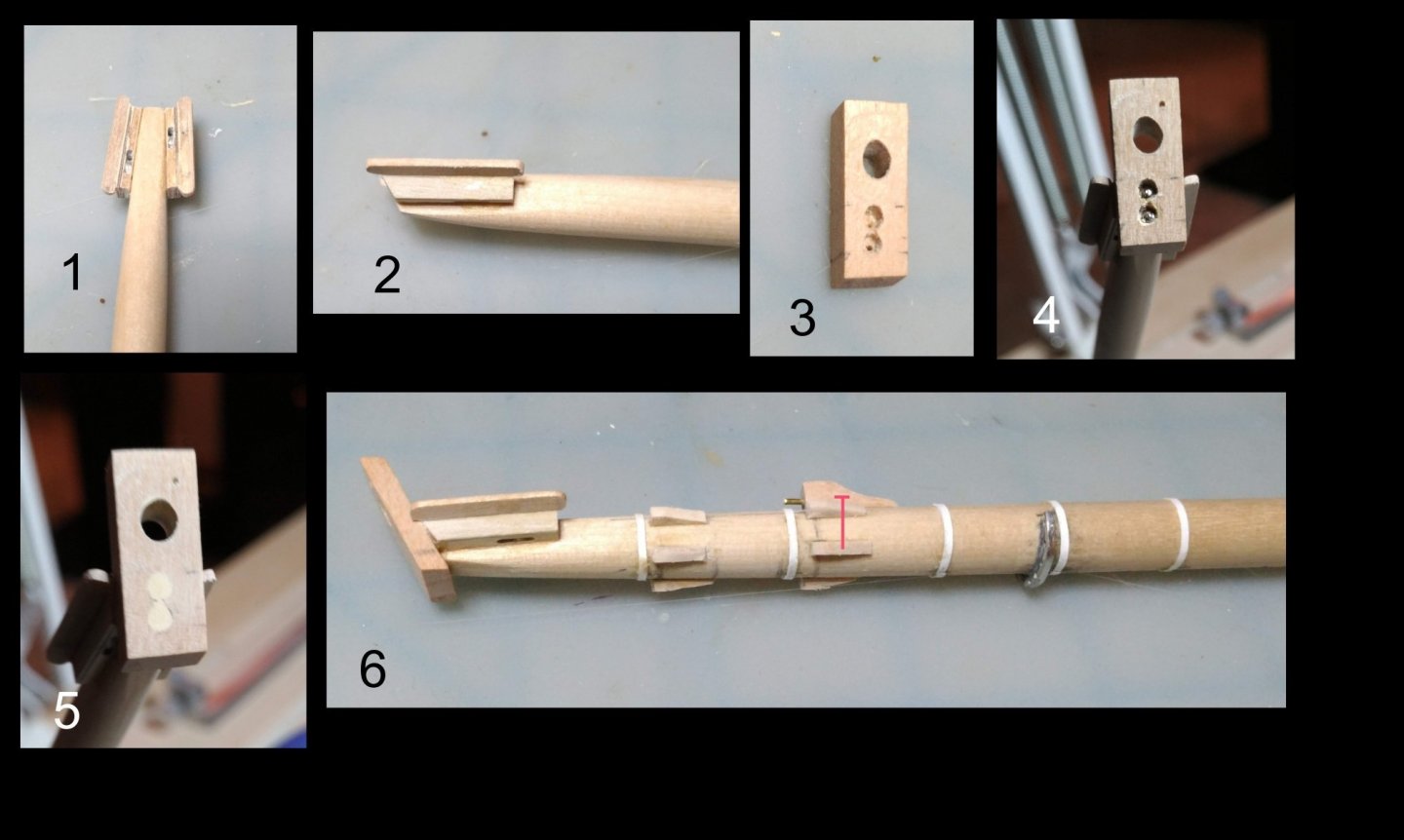
1, 2. Two more views o the completed bees
3, 4, 5. Bowsprit cap showing method of securing it to the end of the bowsprit using reinforcing pins
6. Hoops, forestay cleats, jib boom step, and fairlead installed. The kit does not include a fairlead. I ordered a spare spider ring from BJ. The holes, originally intended for belaying pins serve very well as fairleads. I cut a section out of the side which did not have holes and bent the ring outward very very carefully then glued it to the bowsprit with epoxy.
Construction of the dolphin striker. The red lines in photo 2 indicate reinforcing pins.

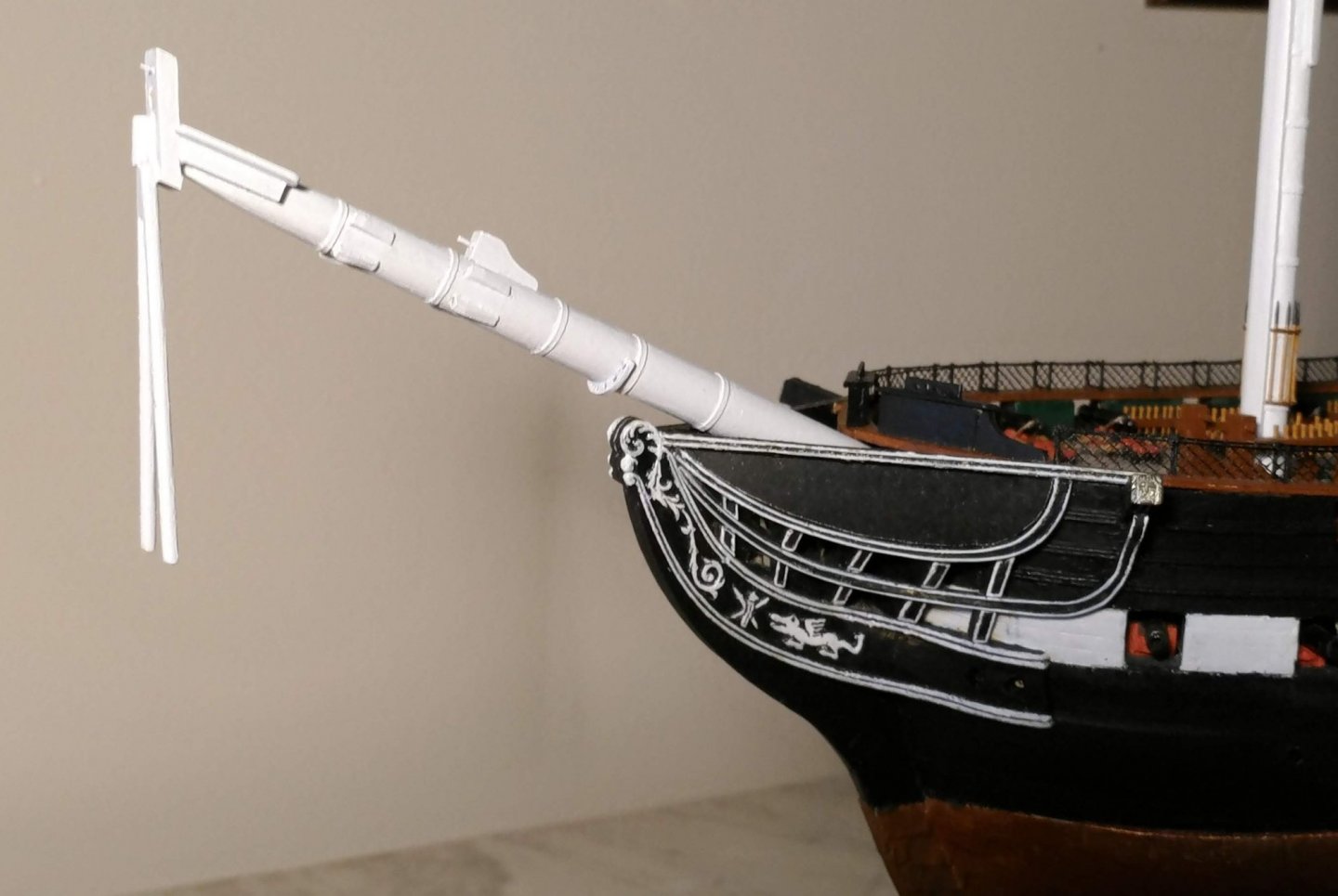
Completed bowsprit painted and dry fitted on the model:
Jib booms installed:
Each boom was tapered by holding it against sand paper taped to the table, and moving back and forth while constantly rotating it.
The jib boom cap is a strip of card stock around each of the two booms, connected by a wire fitted into holes drilled into both booms to receive it.
-
The masts
Bluejacket provides birch dowels for masts and spars. It turns out that dowels that are not warped are very hard to come by. Fortunately the provided dowels were straight for enough of their length to be usable for the lower masts.
Here are some composite photos showing my method for constructing them.
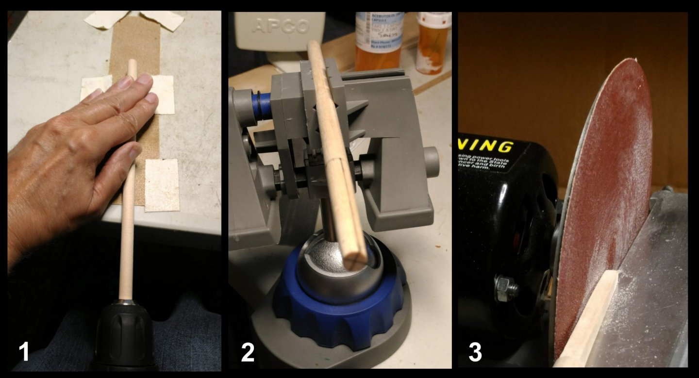
1. Tapering the mast using an electric drill to turn it, and holding the mast against sand paper taped to the table top.
2. The tapered end marked in preparation for squaring the mast head.
3. Squaring the mast head using a disc sander ( hand operated for the more exacting and delicate shaping).
1. Locations of the mast hoops marked out.
2. Strips of 67 lb card stock cut, then glued to the mast using PVA with the seam located in front to be covered by the paunch.

1. Drawing taken from the downloaded MS Constitution instruction manual showing the method for constructing the cheeks and paunch which I adopted.
2. Strips of 67 lb card stock glued in between the hoops to provide a good base for the gluing of the cheeks and paunch.
3. Gluing 1/16" by 1/16" basswood strips to the mast.
4. Strips glued awaiting the filling in of the cracks between the strips with diluted Elmer's wood filler.
5. Filler applied, then sanded down to the correct thickness and contour to form the paunch.
6. A side view of the paunch before and after filling in the gap between the outer edge of the paunch and the mast.

1. Two hound/bib units incorporating the hounds and bibs glued together with rubber cement and shaped, so they would match each other.
2. The two units separated and inscribed with a chisel to simulate the joint between the hounds and bibs.
3. The hounds and bibs glued to the mast, then filled in with wood filler.
4, View of the mast with hounds, bibs and paunch
5, 6. Two views of the mast with the hounds/bibs andcheeks in place.
7. Completed mast with jeer cleats installed.
8. Closeup of the masthead showing jeer cleat construction.
9. All three masts completed and painted.
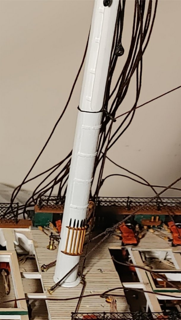
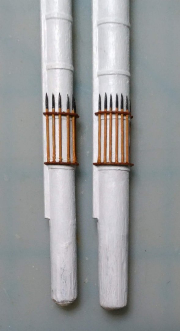
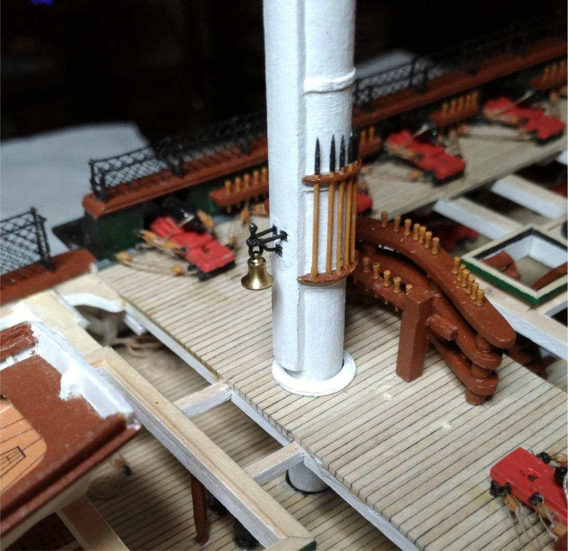
Photo-etched brass boarding pike racks are provided. Boarding pikes are metal castings.
Heads up: Only the very tip of the metal boarding pike will fit through the holes in the top rack, so I substituted #17 pins with their heads cut off, and came up with this arrangement:
The ship's bell is a brass casting. I mounted it on the mast using wire bent to simulate the present arrangement as closely as I could. The bell swings free.
I decided to make and mount the trestle trees at this time.
Heads up: The plan for the trestle trees on the mast plan, and the corresponding drawings on the tops plans do not match, The notch into which the aft cross tree fits is farther aft on the mast plans than it is in the tops plans.
Here they are installed on the masts:
Here are the completed masts dry fitted on the model.
- BenD, GrandpaPhil, Ian_Grant and 3 others
-
6


USS Constitution by KurtH - FINISHED - BlueJacket Shipcrafters - 1/96 - First wood model kit
in - Kit build logs for subjects built from 1751 - 1800
Posted
Can anyone out there tell me what diameter rope was typically used for footropes? My instructions do not have it. None of my books on ship model building have it. I cannot find it by Googling. I imagine it would be the same regardless of the size of the ship. Thanks!