Dr PS - Paul Schulze
-
Posts
304 -
Joined
-
Last visited
Content Type
Profiles
Forums
Gallery
Events
Everything posted by Dr PS - Paul Schulze
-
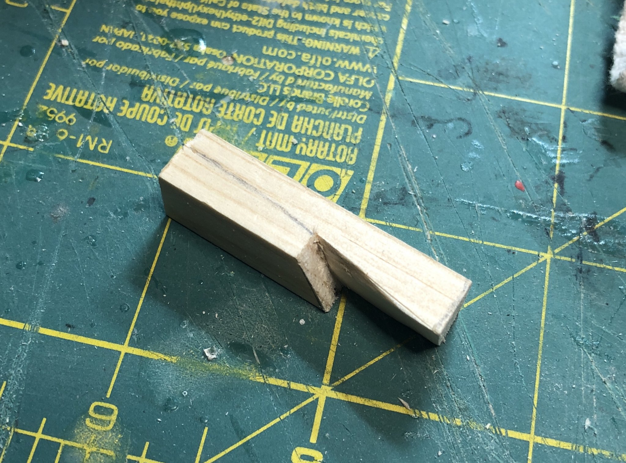
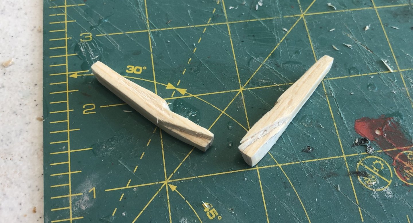
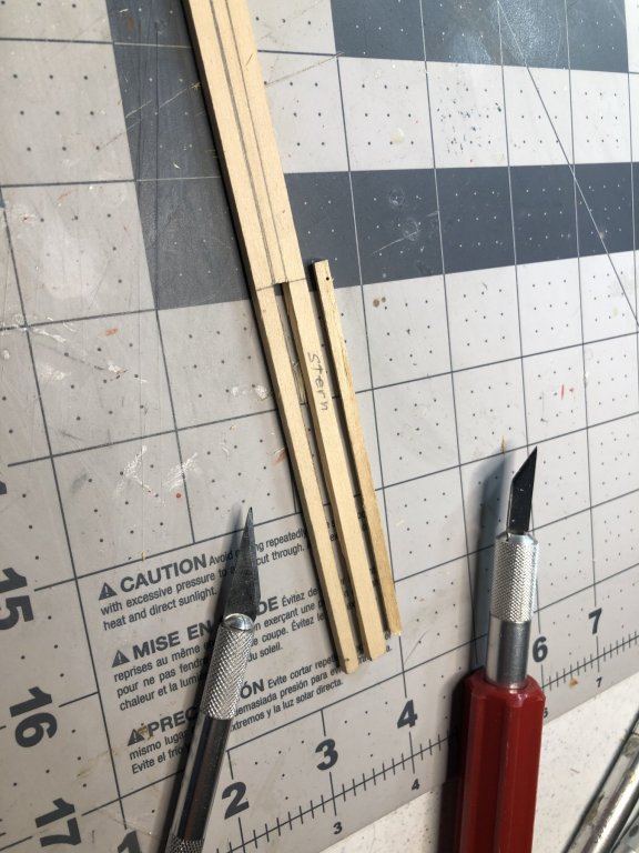
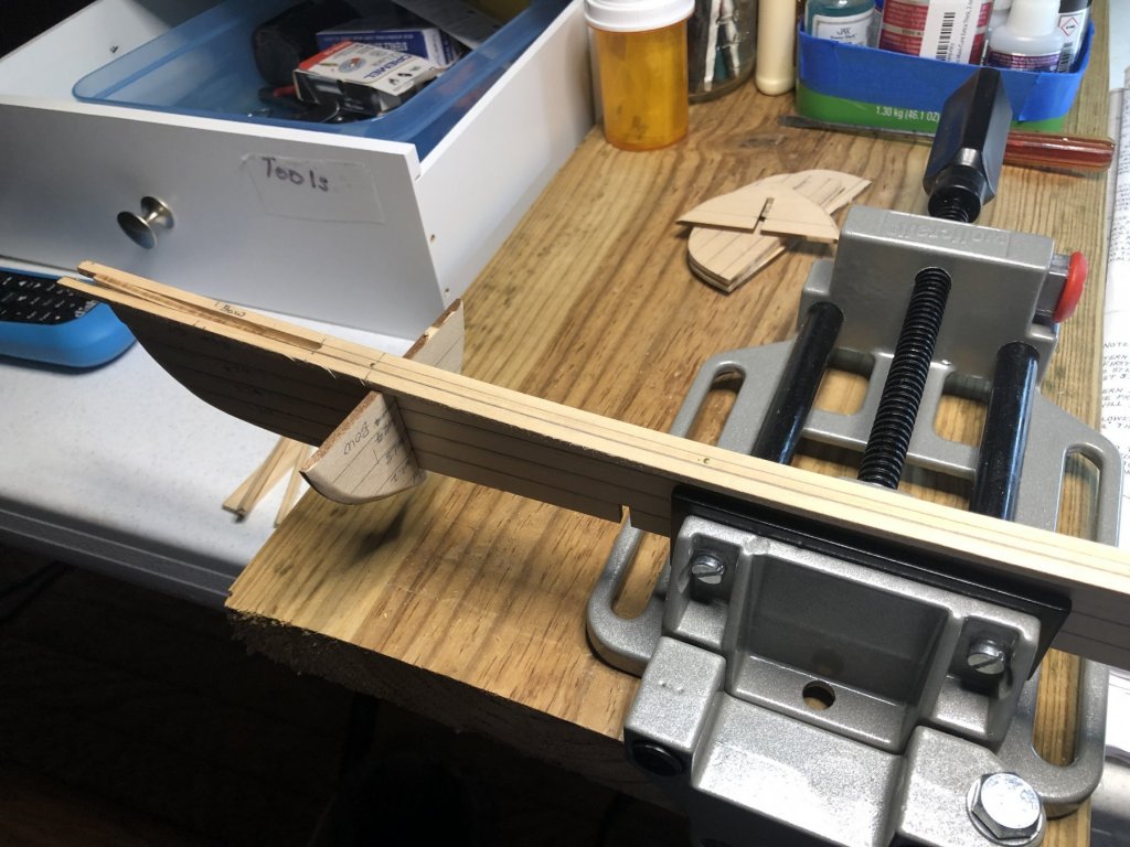
 First cut was deep enough to include the rabbet cut for the gunwales The second was cut parallel to the drawn line to form the outboard side of the Cheek. The rabbet cut was then shaped to give a fit. Finally the scarf was made for the inwale.
- 103 replies
-
- 3
-

-
- new bedford whaleboat
- model shipways
- (and 1 more)
-
I have taken a different approach and think I am on the right track now. I will post my results when finished.
-
I see how cardstock would work great fro 2D; however, the Cheek pieces have a complicated 3D twist with scarfs. I think I can get the scarfs OK if I can get the basic twists down. I can probably used cardstock to get the proper length and height of the Cheek and then do some carving on the resulting block. I will continue working on it - trial and error. If other builders of the MS NBW have scale drawings of the Cheeks, I would appreciate any help.
-
I am having real problems making the Cheek pieces. The dimensions on the plan sheets don’t help very much. I have attempted several pieces and none seem very close to what others have achieved. Not only do I have to get one right, I will have to cut another matching one for the other side. I have several pictures of what others have done, but descriptions are very sparse. Some have indicated that they are not too hard to make. Before I waste more daylight and wood, I would appreciate any tips from others.
-
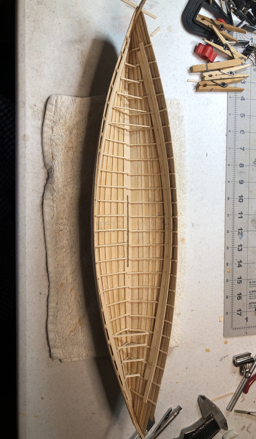
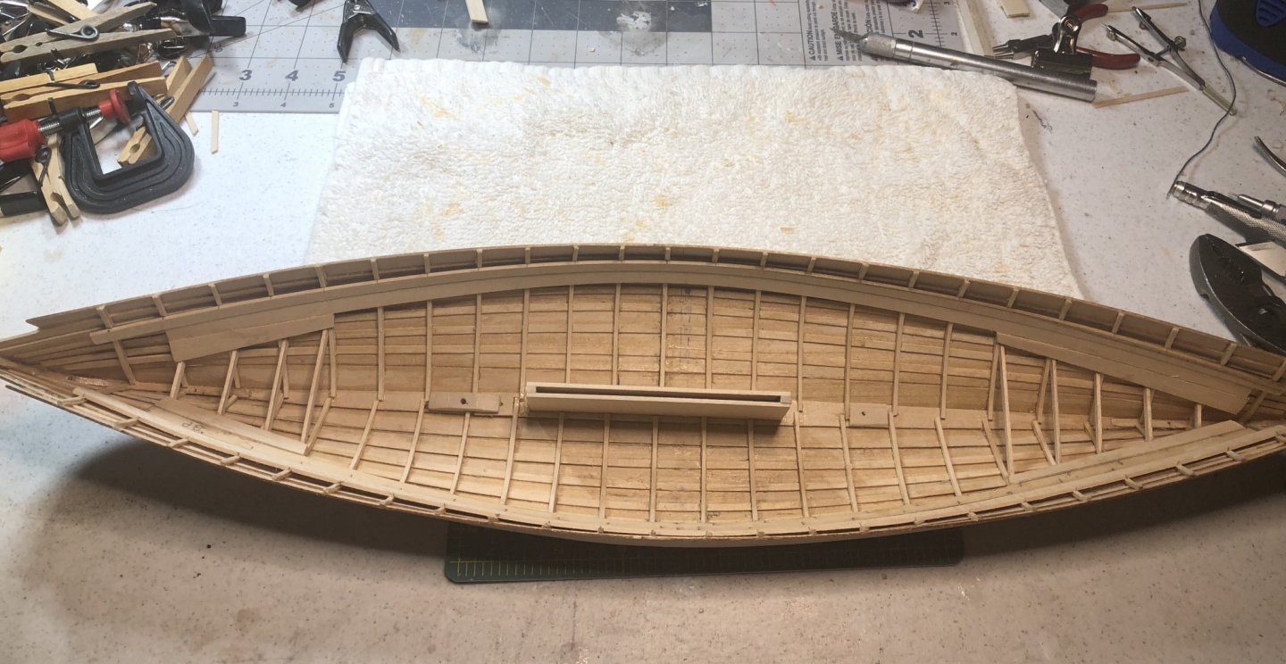
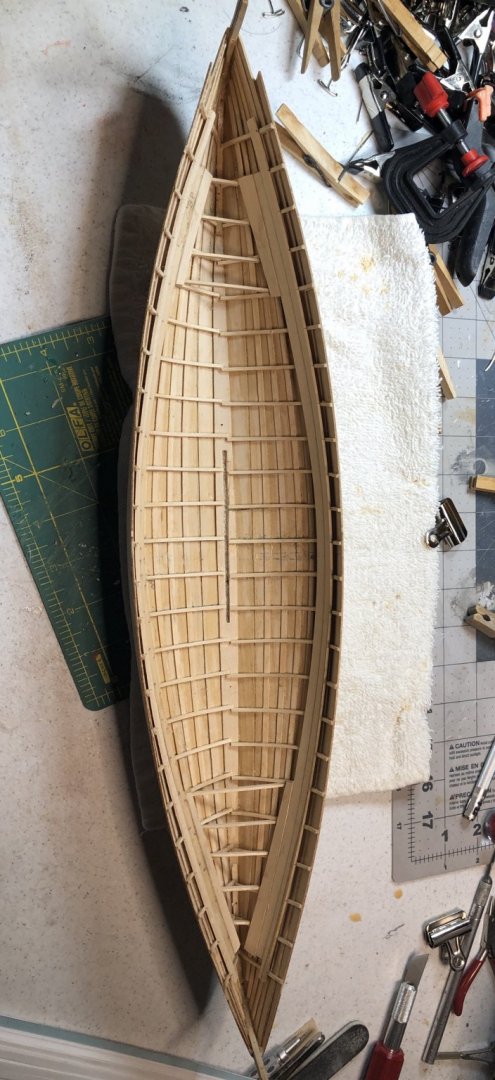
I have completed the ceiling. I used 3/64” x 5/16” strips for all ceiling planks except #6 on the port side where the gap was a bit too wide. Here I cut a plank to fit from a 1/2” wide strip.
- 103 replies
-
- 11
-
-
- new bedford whaleboat
- model shipways
- (and 1 more)
-
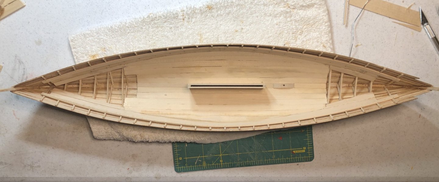
Centerboard Trunk and Mast Step have been completed. Reinforcing strips were glued to the top of the keel in two places for mounting rods.
- 103 replies
-
- 11
-
-
- new bedford whaleboat
- model shipways
- (and 1 more)
-
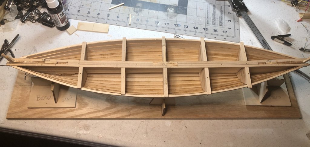
I have now completed installing the Thwart Risers, adjacent ceiling pieces and beams for the stem and stern sheets. The Thwart Risers and Ceilings will be painted so I have chosen not to use nail fasteners. The outer strakes will also be painted. Next will be the Centerboard Trunk and Mast Step.

- 103 replies
-
- 10
-
-
- new bedford whaleboat
- model shipways
- (and 1 more)
-
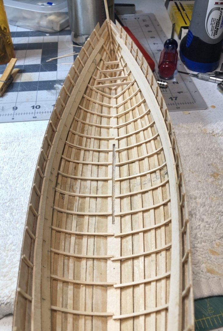
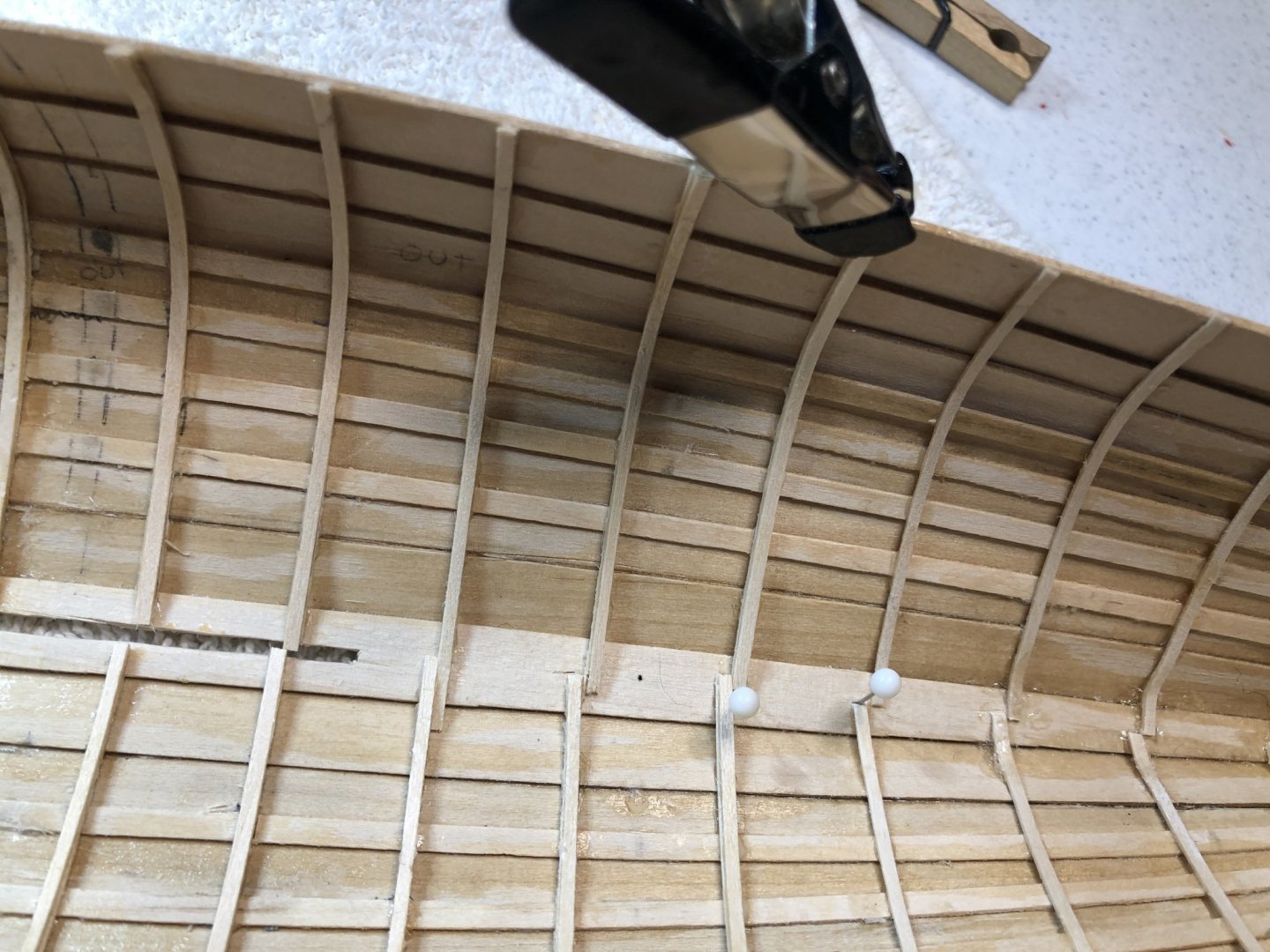
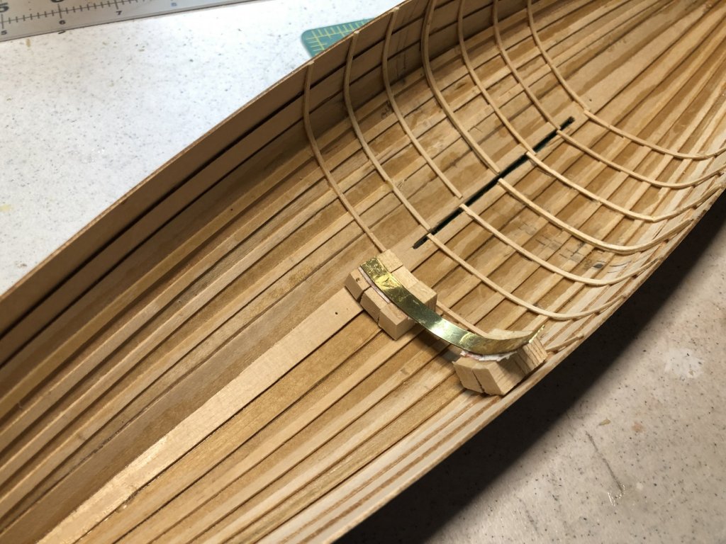
The frames were finally completed. They were held in place for the PVA glue to dry with a clamp at the gunwale strake and a pin at keel. The thwart risers were also attached with PVA glue at a distance below the top edge of the gunwale strake as indicated on Sheet 2 or the plans. The risers were made from kit supplied 1/16” x 1/4” strips.
- 103 replies
-
- 9
-
-
- new bedford whaleboat
- model shipways
- (and 1 more)
-
Looking really good 😎 Aren’t medicine bottles great. What did we ever do without them?
-
John, thanks for the suggestions. I will visit the site.
-
Arthur, the color scheme is my biggest pondering right now. I know Whaleboats were not always painted the same but each company had their scheme for recognition at sea. The recommended colors are not too bad. Other folks building this model have deviated from this, some completely. Curious, do you have any suggestions as to what you would do? As a matter of fact, I would like others out there to jump in on this.
-
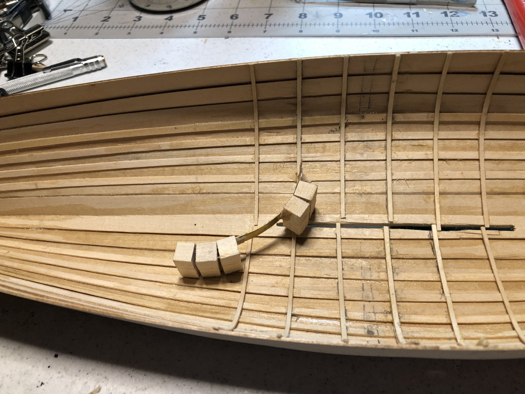
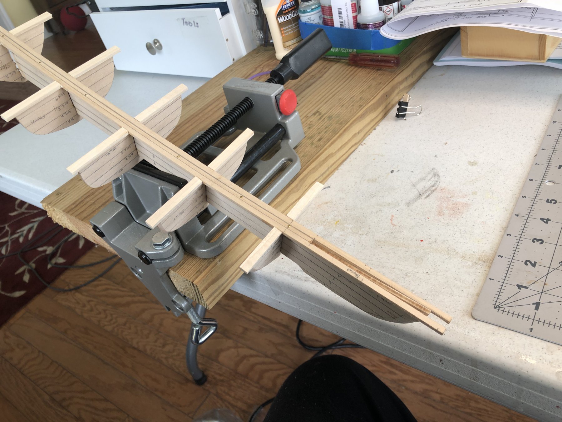
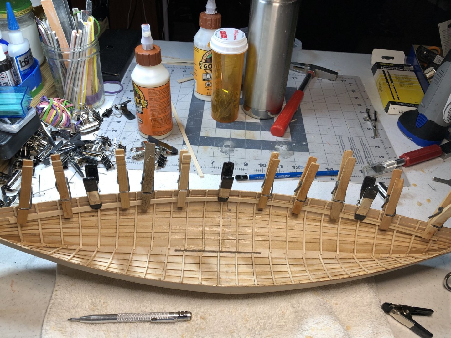
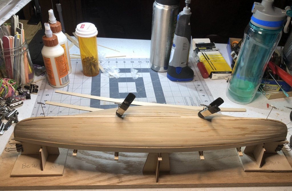
Started framing and decided to make a jig for spacing the frames. The jig was simply made of blocks, cut to the correct length, glued with Extra Thick CA glue to a 1/32” brass strip. The central portion has no spacers so that the frames can be easily positioned. After marking the central frame using mold three, I proceeded to put the bottom half of the laminated frames in place. I expect a few days of work to finish the frames entirely.

- 103 replies
-
- 5
-
-
- new bedford whaleboat
- model shipways
- (and 1 more)
-
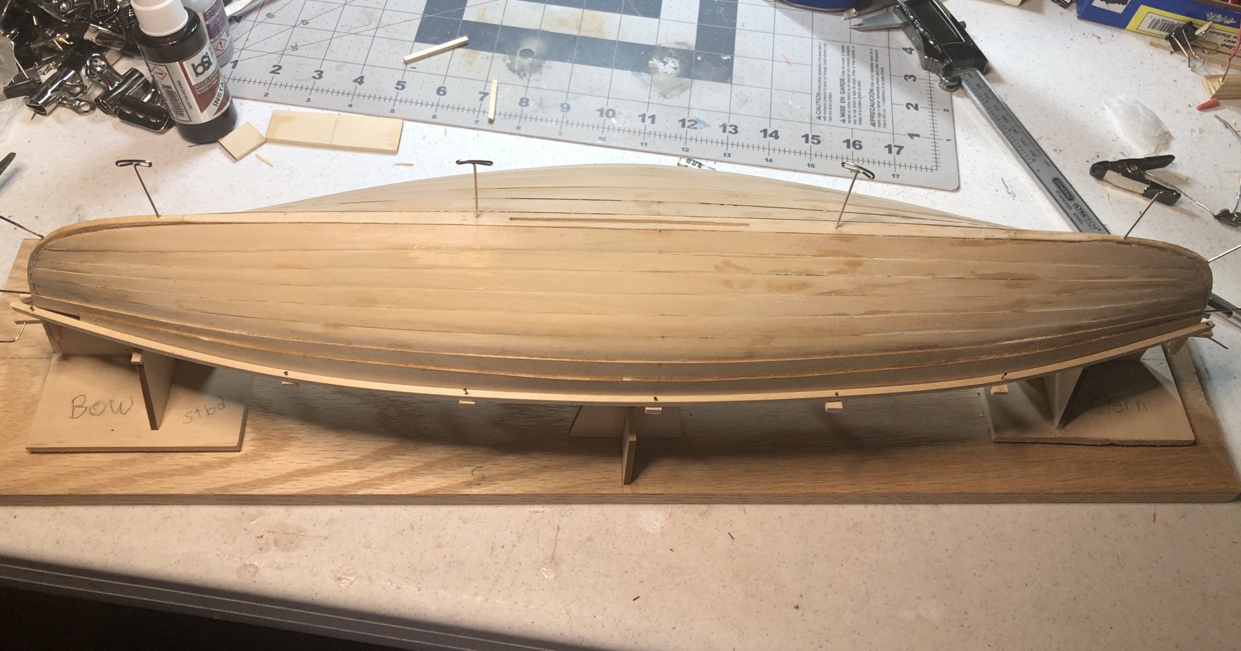
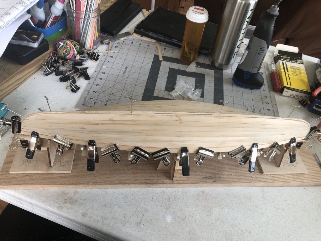
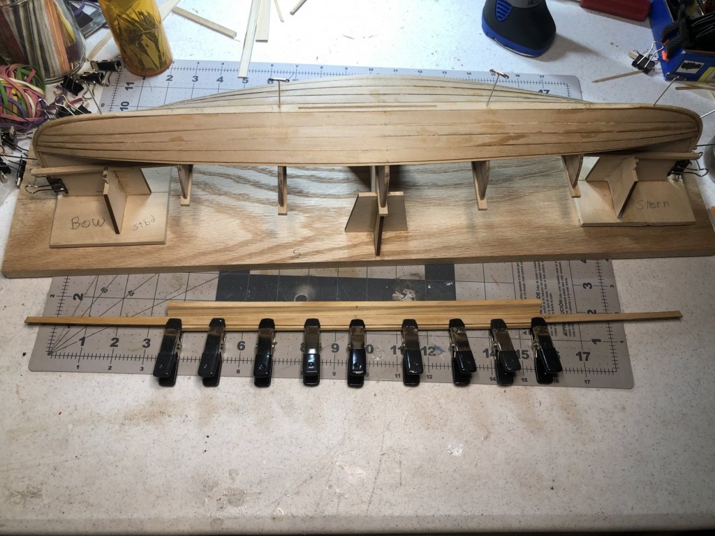
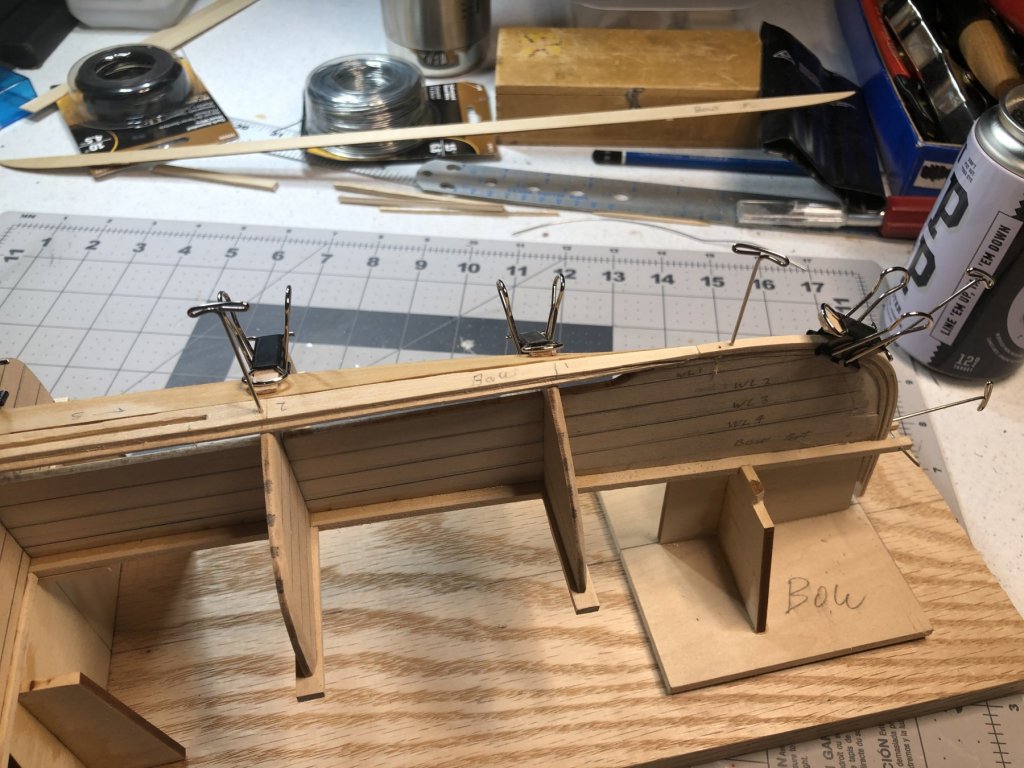
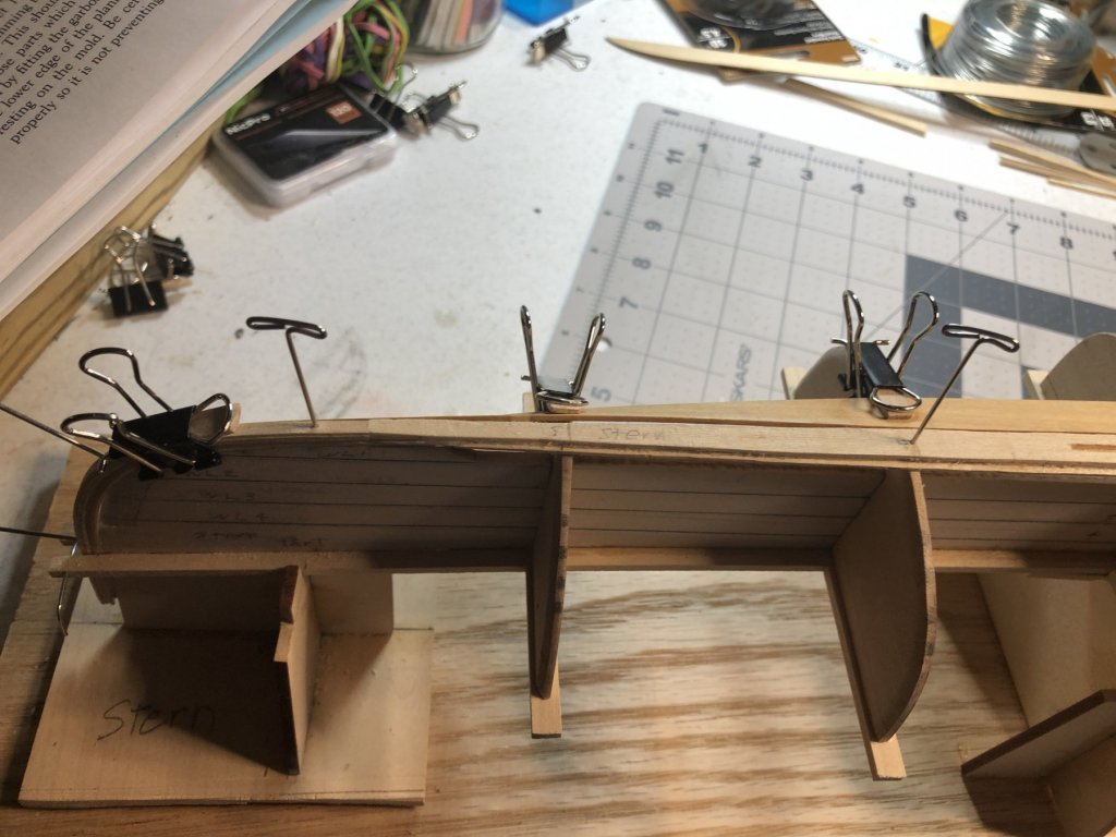
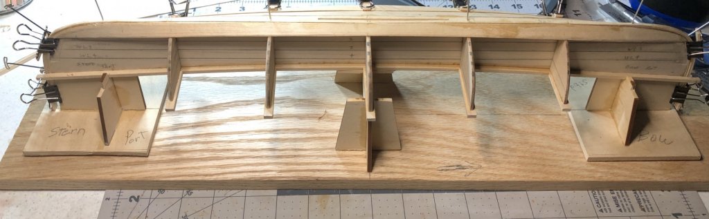
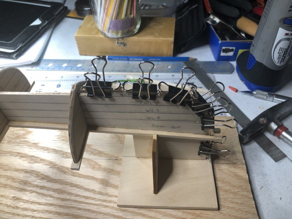
Well, the hull has been built. I noticed a couple of issues which I should have caught and addressed earlier. Looking at the stem from the front, I noticed the strakes below the Sheer are off a bit (the stern was spot on). 😳 The second issue is that the tops of most of the molds do not touch the inboard side of the keel. The latter probably resulted from the fact that I removed the boat from the molds after each strake placement so I could run super thin CA down the seams. Hopefully it will not affect the outcome. Here the Sheer strake is clamped until the glue dries. Below, the Sheer and Gunwale. Below, the boat, retaining battens and molds have been removed from the Horse. Because the boat fits rather loosely, I have decided to do the framing without the molds, etc. Before removing, I will use mold #3 to mark the position of the central frame.

- 103 replies
-
- 1
-
-
- new bedford whaleboat
- model shipways
- (and 1 more)
-
Really looking good. Your heading down the last stretch. I found the final steps as tedious and somewhat time consuming. Have you ever wondered how many builders throw in the towel at this point??? I encourage you to keep up the good work. 😎 I really like your knot board on the wall. Did you make it and do you refer to it?
-
Not too bad! For some reason I find it a bit slow going. The nice part is that the strakes were laser cut but some needed battens attached to them. Soon the fun begins as 24 frames have to be added.
- 103 replies
-
- 1
-
-
- new bedford whaleboat
- model shipways
- (and 1 more)
-
Your Whaleboat looks really great. I hope mine looks that good.
- 45 replies
-
- 1
-
-
- new bedford whaleboat
- model shipways
- (and 1 more)
-
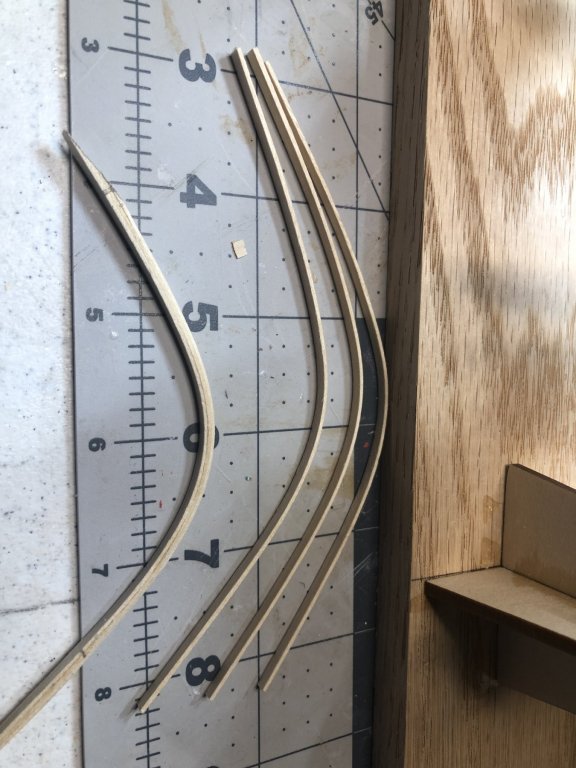
Strakes #’s 2, 3 and 4 were glued into place using CA glue. In order to keep the glue off the molds, waxed paper was slipped between the strakes and molds. The battens were glued to the strakes with PVA prior to placement. Strake #5 is shown below clamped to the provided clove piece for shaping prior to gluing. So far, no real problems have occurred. 😎
- 103 replies
-
- 10
-
-
- new bedford whaleboat
- model shipways
- (and 1 more)
-
Great work! Keep it up. 😎
-
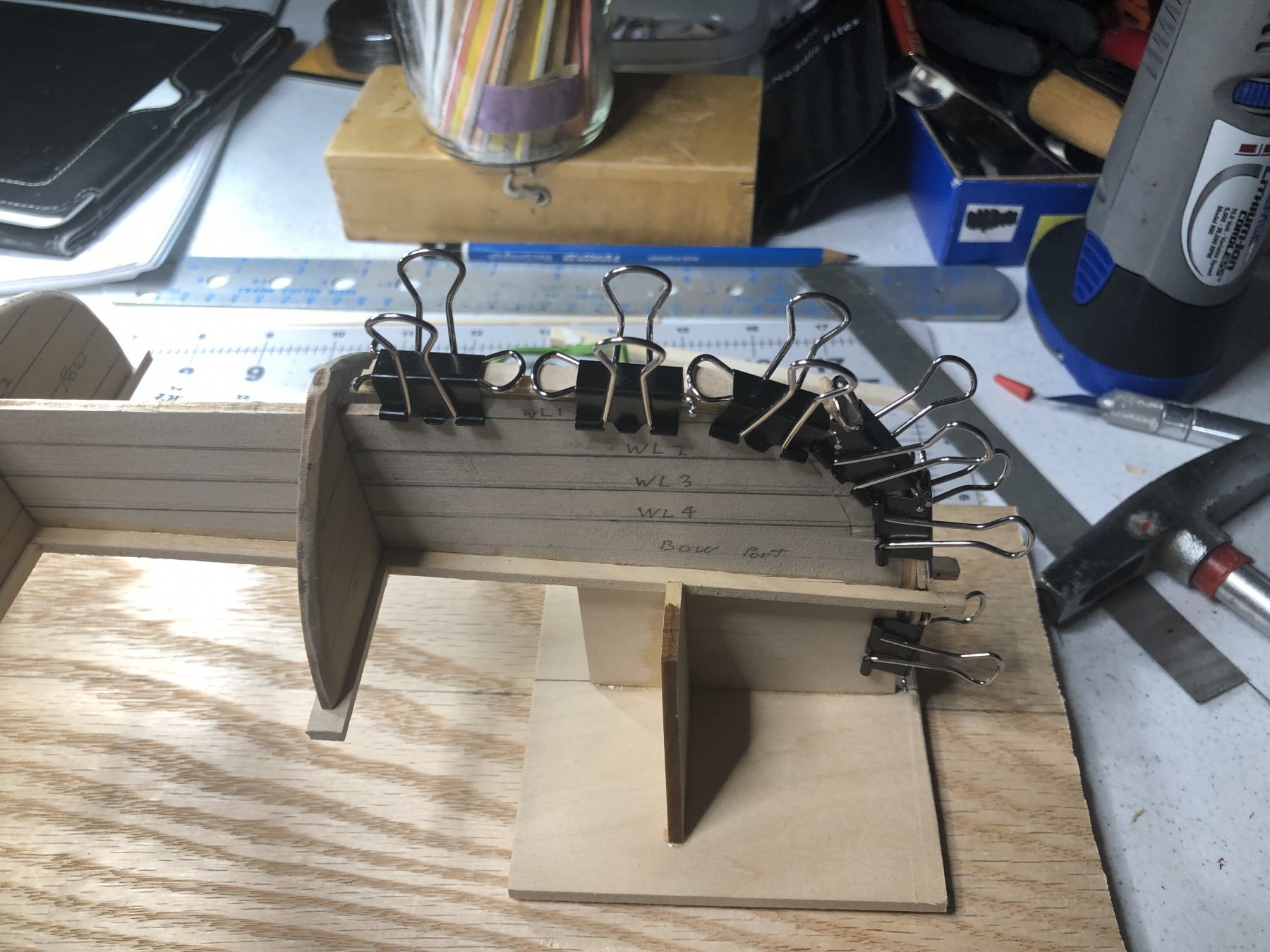
The second laminate layers were assembled and glued. The upper and lower keels were positioned and glued to the laminate layers at the stem and stern.Next, the keel lips and laminate bevels were smoothed at the kerf joints. Then the garboards were beveled on the upper outboard edge, soaked in 50/50 alcohol/water, fitted to the molds and keels, allowed to dry and glued in place using medium and super thin CA glue.
- 103 replies
-
- 5
-
-
- new bedford whaleboat
- model shipways
- (and 1 more)
-
John, I really like what you are doing with your Longboat. She’s going to be a good looking boat.
-
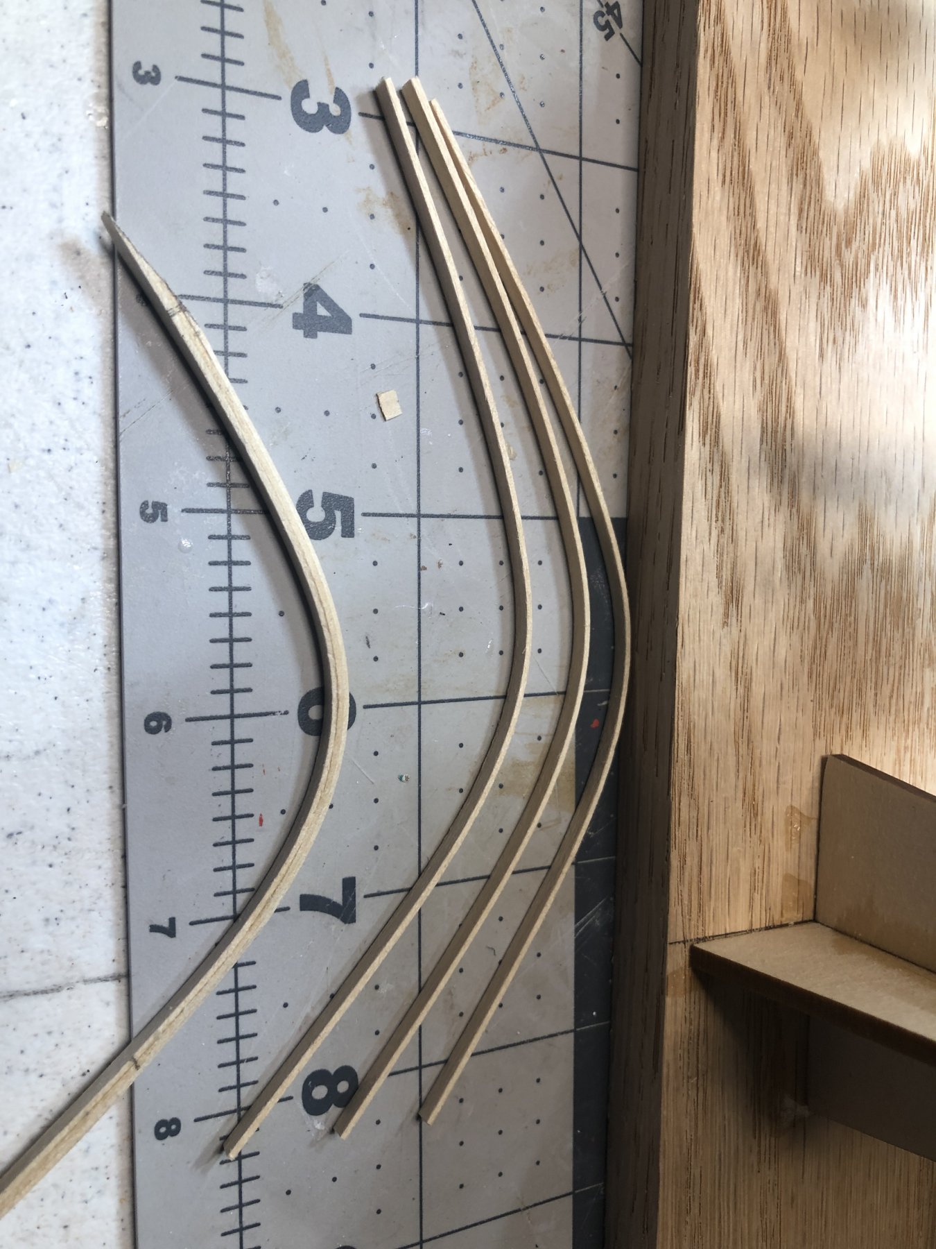
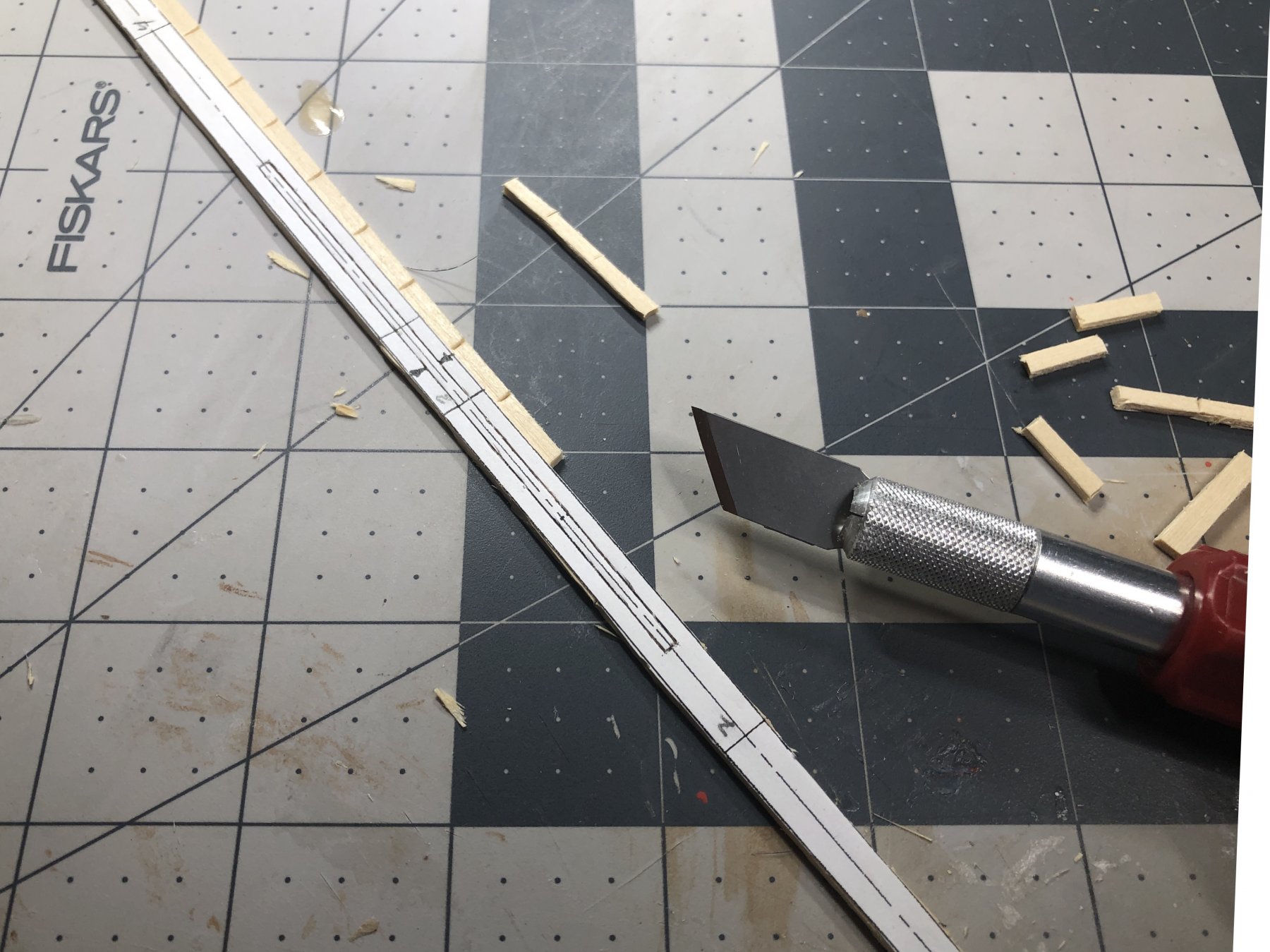
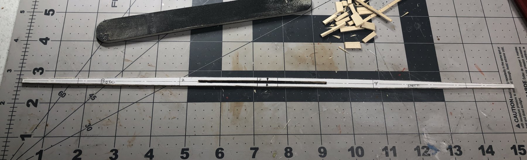
Assembled and glued first laminated keel pieces for stem and stern. Next a copy of top and bottom center keel board templates were glued to 3/64”x1/2” and 5/64”x1/2” boards and trimmed. Only the lower layer has the center board slot cut at this time. The first layer laminate pieces were beveled and the kerf cut. Glued paper is easily removed with application of some alcohol


- 103 replies
-
- 4
-
-
- new bedford whaleboat
- model shipways
- (and 1 more)
-
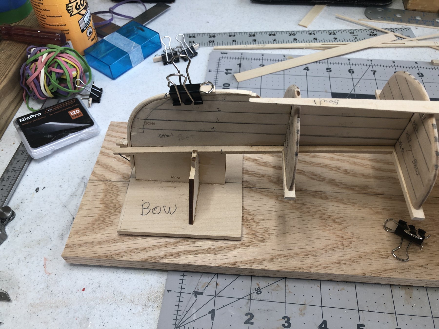
Finally got the molds fastened to horses and horses fastened to construction board. I should have studied the plans a bit more carefully as I glued the fore and aft horses to the cap strip. I don’t think it will pose too much of a problem as they should be fairly easily cut away.

- 103 replies
-
- 3
-
-
- new bedford whaleboat
- model shipways
- (and 1 more)
-
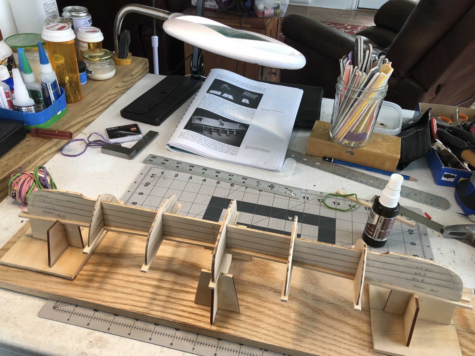
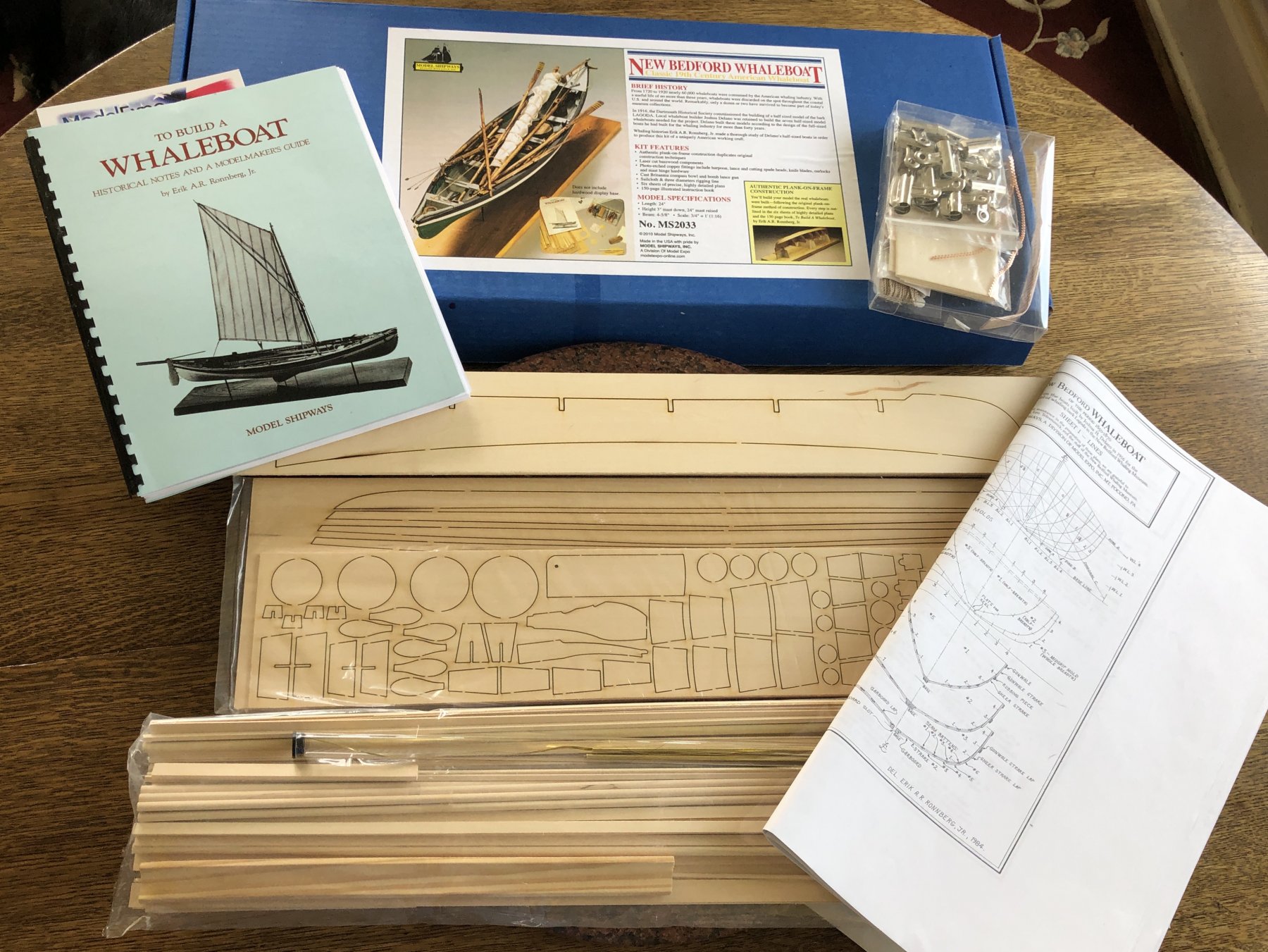
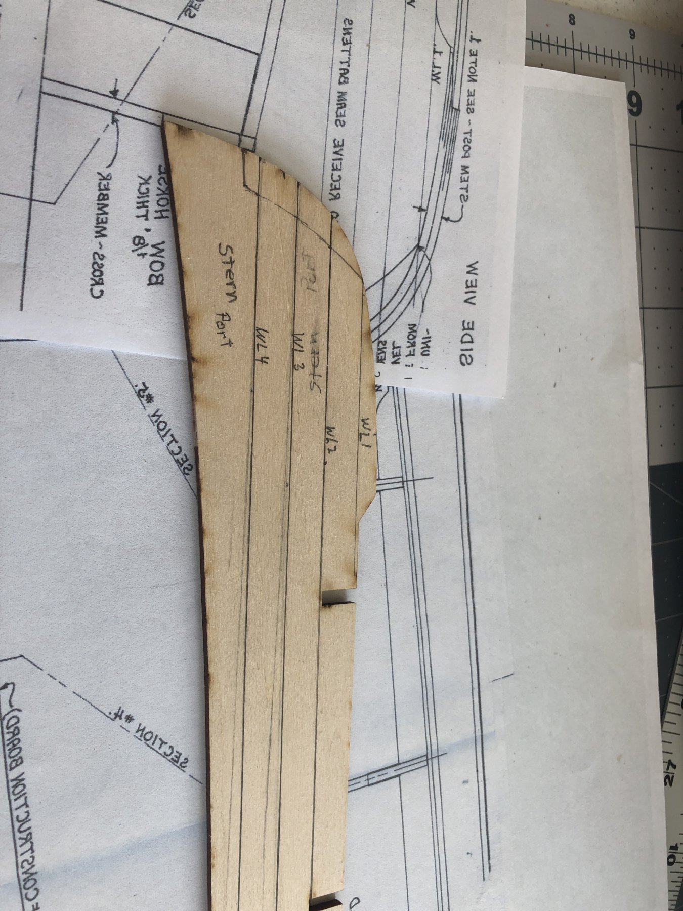
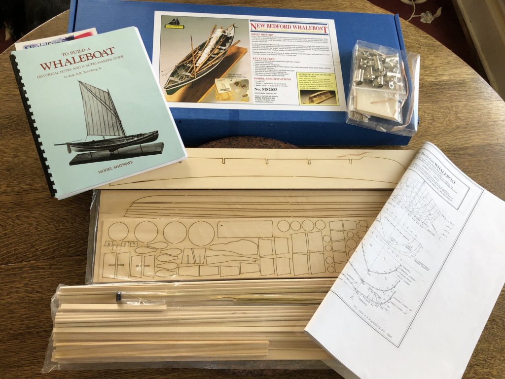
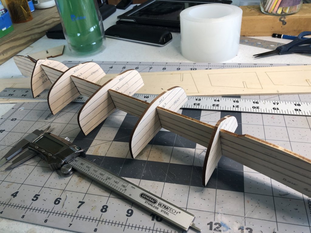
This is my second build log on this site and it is my first POF. There are excellent build logs for the New Bedford Whaleboat here (Carlmb, Mike-In-Ri, Rbohlman, Senior-Old-Salt, Soup591, Ziled68) and elsewhere (https://www.charleswmorganmodel.com/whaleboat-build-log-by-john-fleming.html). As a result of this, I will post progress pictures and make only brief comments where necessary to point out peculiarities found during my build. First the kit: Marked waterlines on profile mold. Fitted section molds. Cut notch in cap strip. Fitted with cap strip. Glued cap strips and section molds to profile mold.


- 103 replies
-
- 4
-
-
- new bedford whaleboat
- model shipways
- (and 1 more)
-
Hello Tony, I think you are doing a super job on this build. I am impressed by your workmanship and techniques. Your log is great. You know, there are so many tricks of the trade for achieving sometimes very difficult results on a particular step that I wished someone could put together a compendium of all these techniques. Oh well! Keep up the very good work. 😎 Paul
- 124 replies
-
- 4
-
-
- longboat
- Chaloupe Armee En Guerre
- (and 1 more)