HOLIDAY DONATION DRIVE - SUPPORT MSW - DO YOUR PART TO KEEP THIS GREAT FORUM GOING!
×


src
-
Posts
2,300 -
Joined
-
Last visited
Content Type
Profiles
Forums
Gallery
Events
Everything posted by src
-
RIch, That looks really good! Varnish will come out glossy unless it has a flattening agent added in although you can rub it down to whatever sheen you want with steel wool. It will also add an amber tint to your wood and will continue to yellow as it ages. Some people like the effect, some don't. A good water-base clear in the sheen you prefer - you mentioned matt - won't yellow nor will it change the color of your underlying paint. Judgment call on your part. Hope that helps. Here in the States we have something called Frog Tape, works really well. Its very flexible and as long as you rub it down well, it won't bleed. If you decide you want to try something other than the Tamiya tape, look at an automotive paint supplier. Another way to limit bleeding is to brush/spray a thin coat of clear after masking then lay your color down. The clear will seal the edges of the tape. Make sure your clear and color are compatible; experiment first. Sam
- 414 replies
-
- 1
-

-
- caldercraft
- victory
- (and 1 more)
-
Rich, those look good. Probably to late but chucks winchelsea log has some great info on galleries into opinion. I lurked in his build several times as I was working through my badges. Sam
-
Nice work Rich. Sam
-
Mark, I hadn't thought of a drill motor and a file. Come to think of it I could have made a walnut dowel and run it through the kit part and turned a small finial on it that way. Bah! wheres the fun in that?!! This way I get to throw more kit parts in the scrap bin. Steve,Thank you! If I can turn a better part than that one on the right then that one is going on. With the exception of the points being off center I am very pleased with it. I am also thinking of taking Marks suggestion about the drill motor and trying to turn a small finial out of brass or boxwood, that will help hide the off center points. It won't happen today since its Mothers day; today I get to sharpen cutlery for mom, sister-in-laws etc. as well as cook dinner. Flesh seared on the grilling device in the backyard, NOM-NOM! Sam
-
Welcome back Brian and thanks for the kind words. Ill be watching for the update on your honeymoon, hopefully it was the trip that went poorly and not the honeymoon itself. The capstan is only partially custom, most of the parts are from the kit. I only replaced the drum head and the center shaft and that was just to give myself a flat surface to glue to. Sam
-
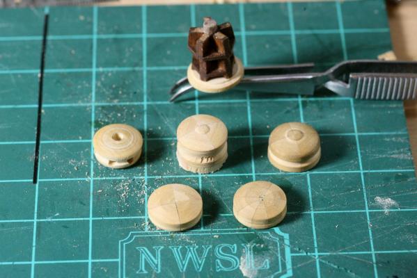
A quick update. I have spent what build time i've had this week drilling for ring bolts to mount the gun carriages, remounting my pinrails - somehow i mounted them way too high. Its been staring me in the face for months and I never noticed it! I also had to re-blacken a bunch of ring bolts, they had accumulated some white powder on them so I scrubbed them down and re-blackend them. I was never really happy with the color anyway, they were more brown than black. A couple of weeks ago I started in on the capstan. I didn't like the drum head that came with the kit, there is a hole drilled all the way through it to mount it to a dowel. The dowel seemed kind of small so I made a five sided shaft out of walnut and glued the whelps to that. Naturally after that I just couldn't leave things alone so I had to add in the chocks since they didn't come with the kit. Then it was time to do something about the drum head (trundle head?) I started out copying the kit supplied part but didn't like the result I was getting so I went with just a flat face on top with a slight angle return. I've turned this part several times now and think I am getting close to something I like. The first couple were made from four plane mitered together and then turned on my little 15" lathe. I screwed those up royally trying to turn them with carving chisels; They work great for turning small parts from 5 and 10lb from but not so much on wood; they are too thin/light and chatter or skate across the wood as it turns. My smallest skew chisel for lathe work and needle files turned out to be the way. The last set I glued out of ten pieces of boxwood mitered at 15 degrees each. That came out pretty good except where the points meet isn't quit what I want. I may need to find a thicker blade for my Proxon table saw, The blade I have vibrates too much at the start and end of a cut and by the time I have cleaned up the cuts the points are all chewed up. If I can't get a better part then the one on the lower right in the picture below will end up being what I go with. I won't love it but it may be the best I can do at this point.
-
Looks great Rich, whats wrong with the water line? Sam
-
Rich, Thats a great idea! I have contemplated that but there are a couple of builds I want for myself first, call me greedy! Keep us posted on the donation process. Sam
- 1,756 replies
-
- 2
-
-
- constitution
- constructo
- (and 1 more)
-
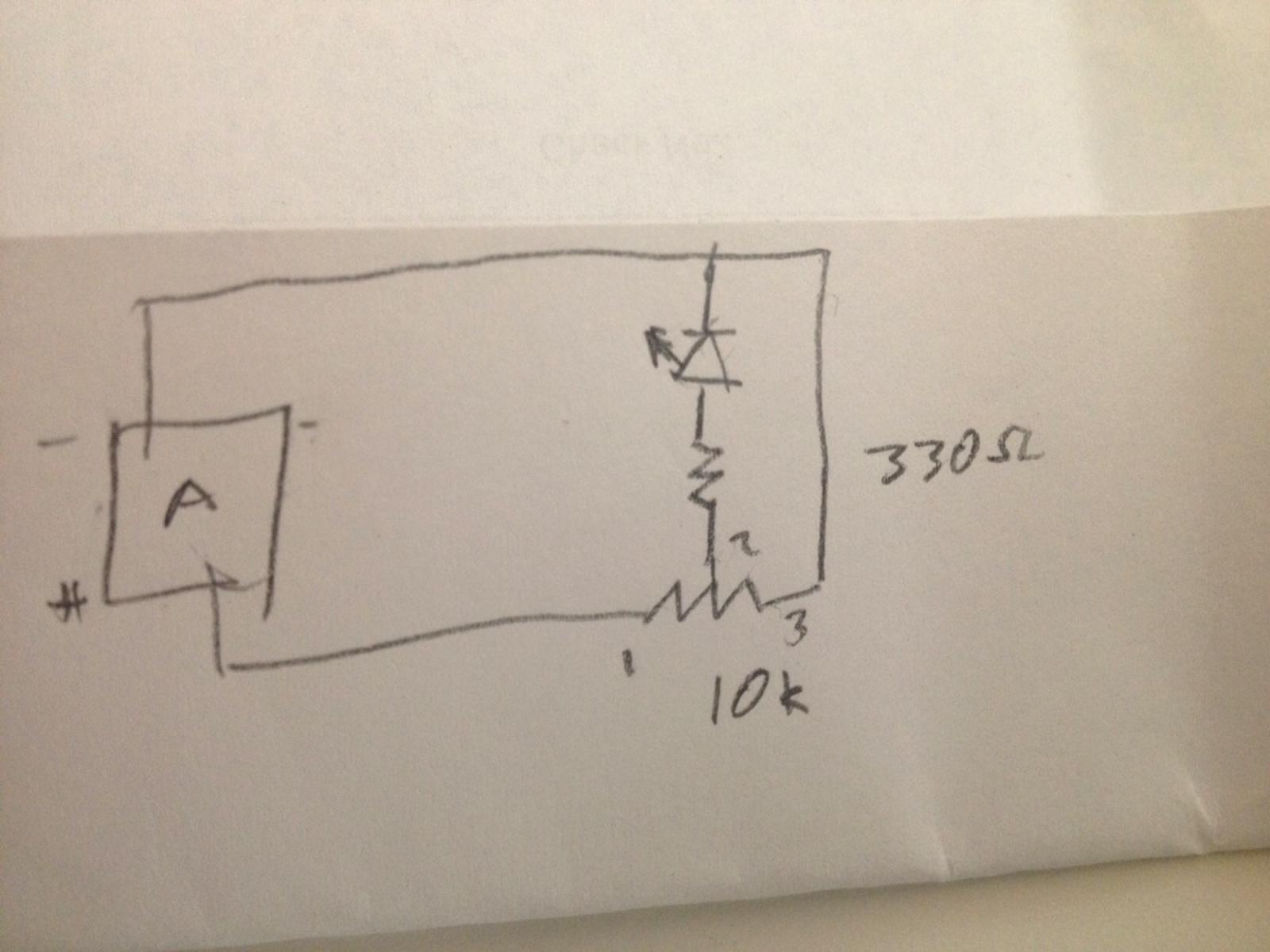
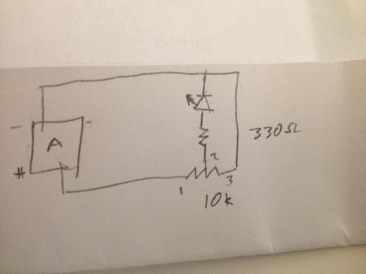
Mark, thanks for the advice, wasn't aware of the feedback voltage. Even though I got it straightened out I decided to try your way (yes 2 is center and one and three are outer) it works that way too but I can't run the LED down to completely off if I don't run the third leg to ground. Also running a 330 ohm resistor between the pot and the LED. Essentially I have duplicated the schematic below 3 times. Each circuit has its own digital out and then returns back to a common ground on the board. Just for simplicity sake I removed the second ground off of the Arduino and jumped from one ground rail to the other on the bread board, naturally no change. Sam
-
Carl, Diodes of which an LED is will only allow current to pass in one direction, so to answer your question yes it is important + vs -. I found my problem, I was outside attempting to turn a trundle head for my capstan - an adventure for another post - and it kept bugging me. After screwing up my mini lath work I came in and sat down and looked at my wiring again. The Arduino board has two ground taps. I ran the first one to ground on the left side of the breadboard, that was grounding my original circuit. I ran the second ground to the right side of the bread board (there are common positive and negative rails on each side if your not familiar with a bread board) that was all well and good which was why I was scratching my head. Then I followed the lead from the neg rail back to the Arduino.........tied in to the 5vdc out which is right next to the negative tap!!!!!! Doh!!!!! Remember what I said about knowing just enough to get myself in trouble?? The smoke stayed in the wires and the genie still lives so no harm no foul. Sigh.... all is well now, everything behaves properly. So Carl in a sense you had it right. Sam
-
Siggi, thanks for the information, it does help. I agree, some mini tools would be nice along with that microscope. Sam
-
Carefull, word play is one of my favorite pastimes!! I drive the guys to distraction at work with puns, they hate it. Whats worse, our Draft-lady extrodinare, Miss D makes up here own words to describe things. She doesn't understand that "Words Mean Things" Grrrr... Anyway, For some reason I was thinking I could only control the brightness of the LED through the arduino. I was looking at the circuit yesterday morning before I went to work and it hit me, "What is a potentiometer? its just an adjustable resistor!!!" Sam ya big dummy! I dropped o trim pot in and sure enough i can dim the overall brightness of each led separately. I will still need to adjust the coding to get a more scale like flicker. Assuming the avarage viewing distance is 1-2 feet thats 50 to 100 scale feet. I am thinking the flicker is too great. Its "just" code so its easy to go back. One strange thing that did crop up when I put the trim pots in, if I adjust all the way one direction the LED brightens up the way you would expect, when I go the other way it dims then when I get about 3/4 to 7/8 of the way it suddenly gets REAL bright. Kill the Genie bright! Not sure whats happening here, I tied pin one of the pot to the signal from the arduino, the center pin (pin 2) to the current limiting resistor (330 ohm) and pin 3 to a common ground on the Arduino. Hmmm It can't be back feeding can it?? I would think the LED wouldnt "see" that voltage. This is where I get all messed up with electronics. I know just enough to get myself in trouble...... Sam
-
Very nicely done! More acrylic (plexi)? Lighting those would be a challenge. How big are they, 1-2mm wide? Slightly off topic, would lanterns like these ever have been hung from yard arms at night? I am thinking of the 17th century version of todays port and starboard lights. Sam
-
Mark, looks great from here. I would say that absolutely passes the macro test. I don't see any LED lighting yet...... Sam
-
Sjors, 1981 isnt OLD!!!!! I was still in high school and that was only.......... um, looks at fingers looks at toes 34 years. well ok maybe it was a while ago. Have fun!! Sam
- 1,616 replies
-
- 4
-
-
- caldercraft
- agamemnon
- (and 1 more)
-
Oh no Rich, thats an ax-ident waiting to happen!
-
Watts?? Amps??? What are those?!?!?! Sam
-
Thanks for the kind words Mark. Great cabin huh?? I still have a lot to learn..... The arduino is pretty flexible, there are both regulated 5v and 3v voltage taps available although I would loose the PWM control the way this program works I believe. There is a way to control the brightness through a pot, by adjusting the code or by changing out the resistors. The pot would be global although I understand there is a way to add pots to each PWM-out channel. I think the cleanest way will be to adjust the code though. There are 3 similer lines in the code; analogWrite(ledPin2, TrueRandom.random(0,255)); ledPinX sets the ID of the LED (as I understand it) TrueRandom.random calls up a subroutine (?) that creates the random flicker. (0,255) sets the range of brightnesses of the random flicker. 0 being off and 255 full brightness. By lowering the 255 down to say 200 or even lower will cap the max brightness. Raising the 0 to 75 or maybe more will keep the flicker from going completely black. I played with it a little bit last night but will wait until I have the board together and some sort of mini molex connector or something to connect everything. Since I already killed one LED I want to avoid doing that again, once bitten twice shy you might say. As far as your Connie, they are all wired in series? Unfortunate that is. The Lycorn however. Lots of time and space to wire up something there. Sam
-
Thanks everybody, much appreciated. Having put those lights in 5 years ago, well two of them at least, I have learned a bit about lighting since then and would do things differently today. Eliminate the "Light bar" effect, all the windows shimmering at once doesn't work. I think a better way to have done this would have been to put separate light sources in the badges, one one each circuit to look like divided rooms since I am assuming each one of those windows opened on a separate living/work area. Heads believe? Use a better diffuser method, smaller LEDs or even fiber optics. Allow for replacement of damaged components. 'Cause stupid lives around every corner. All in all I don't regret doing this, just detailing items for the future as well as anybody following behind. I like the Arduino system, especially since I don't need to learn an entire programming language. since its open source I can tweak something that already works and not take too much time away from building. Carl, I understand, like I mentioned above I would go in a different direction and do more experimenting if I had it to do all over. At work we have been doing quite a bit of lighting with RBGW LED as well as some fiber optics. I think fiber optic would offer a much more scale effect in this case. I suspect a simple LED would work for lighting an area such as a gun deck. Onward! Thar be cannons to mount!!! Sam
-
Steve, No but I did do the LaBomba once on a table, does that count? I programed the Arduino tonight, well actually I did a cut and paste from here: http://www.instructables.com/id/Flicker-up-to-6-LEDs-with-Arduino/?ALLSTEPS It was pretty straight forward. I put everything together on a bread board and tested all three circuits and was ok with what I saw. One of the lines of code; analogWrite(ledPin2, TrueRandom.random(0,255)); sets the brightness of the flicker. 0 is off and 255 is full brightness I think I will play with those numbers and try to get a more scale flicker. Well now, Google is insisting on my phone number to verify my identity so I can upload to youtube. I have no intention of giving them my phone number. The video are linked below. They have been scaned for viruses. I understand if you don't want to download a link from somebody you don't know. If you choose to click I hope you enjoy. Sam Arduino flicker.MOV ship flicker.MOV
-
Carl, Augie, thanks!!! Had it been the side lighting I would never have tried it. I was relatively certain I could get the door off and get at the light forgetting how far down and back I placed it. It was in its own personal little bulkhead with a holder. I did expect more wire to be available though, I suspect it was hung up on something. Bravery is just foolishness that doesn't get you hurt... Lesson learned, never feed the Light Genie more magic juice than they can handle. Like a goldfish they will gobble up everything you give them, then keel over. Sam