


stuglo
-
Posts
707 -
Joined
-
Last visited
Content Type
Profiles
Forums
Gallery
Events
Everything posted by stuglo
-
Swan-Class Sloop by Stuglo - FINISHED - 1:48
stuglo replied to stuglo's topic in - Build logs for subjects built 1751 - 1800
On further thought, I can lower timberhead/bridging assembly and corresponding rabbet beneath the stem etc -
Swan-Class Sloop by Stuglo - FINISHED - 1:48
stuglo replied to stuglo's topic in - Build logs for subjects built 1751 - 1800
Much appreciated . What would you do with the situation as ? Is there an alternative to remaking from lower stem upwards? I will of course rework from the 1st cant aftwards. -
Swan-Class Sloop by Stuglo - FINISHED - 1:48
stuglo replied to stuglo's topic in - Build logs for subjects built 1751 - 1800
Hawse piece #2 started this yesterday- The TFFM advice is detailed and again I appreciate the amount of work and expertise involved in preparing this. Blanks of 7.95 are prepared -the angle of bevel remains 34.5 (but check anyway). In order to compensate for the air spaces, spacers of 0.4 and 0.8 are prepared from slivers of wood and doubled card. Some confusion as to which line forms the base of the bevel, but its the one that is perpendicular to the keel and abuts the fore aspect of 1st cant. The beveled piece should now fit nicely between the cant and foot of timberhead. Port good, starboard not so. Despite fixing and checking there has been some shift. I avoided clamping and used trunnels, but in any case the joint isn't straight. Separate with alcohol, refit and restick. Today: The cant seems to be OK. Next problem is how the hawse #2 sits against the timberhead, ? height ? forward extension. When taking height of opening from plan, the piece sits too low. Align height of air space (marked on plan) and top of piece to timberline (height of bridging chock ) and opening 3.5 mm (about 7in real) lower. The book says go by the plan but why discrepancy? Should the position of opening define height/position of piece? I don't want the inner hawser hole to open into or beneath the deck!! After 3 hours of thinking and remeasuring (exhausting) going back from the very first instructions and checking everything from the keel upwards it seems that the upper parts, tip of stemhead+1mm, top of chock +2.5 mm. ? where the error. Nothing dramatic, but the black paper (3 times) thickness of glue, maybe . The steps of the apron are about 2mm too high and aft end lower stem is 1.0mm too wide. These accumulate. I think a lack of experience and leaving too much margin is part of the problem. *** The internal build will be according to plan. At this stage I don't think I need to start again. If necessary I will adjust my timberline (slope above fore cants) when frames are in place. I would be very appreciative for advice on how to proceed. *** -
Swan-Class Sloop by Stuglo - FINISHED - 1:48
stuglo replied to stuglo's topic in - Build logs for subjects built 1751 - 1800
Funny how notice things in picture not when seeing the model- the "hats" on the timberhead , especially the port, are not on straight. To be corrected . -
Swan-Class Sloop by Stuglo - FINISHED - 1:48
stuglo replied to stuglo's topic in - Build logs for subjects built 1751 - 1800
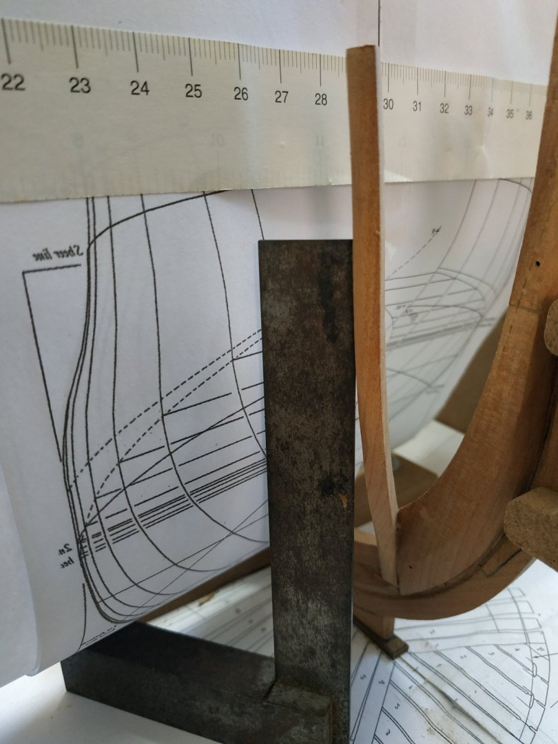
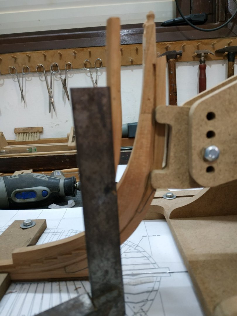
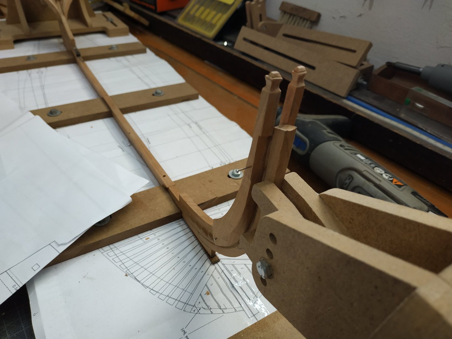
Cleaned up bridging chock to blend with bevel of timberheads- looks OK to me. Ist Fore Cant frames: Referring back in TFFM-"all cant frames are 9ins"- 4.77 mm in our case. After experience (not so happy) with half chock aft , I'm going to cheat , do it as I piece and simulate the chock.There will be many more opportunities to make to make chocks, but the house pieces depend on the accuracy of this piece. Made an extra wide blank to accommodate this, as well as some trunnels for fixing glue parts -wood rather than copper or nylon more appropriate. The UNDER bevel at the foot is at 34.5deg. It sits on 1st step behind a will also be glued to the foot of the timberhead. Make in usual way - stick cut outs both sides, under bevel by angled disc sander etc.Make faux chock marks. Remember to mark port and starboard parts to be removed when bevelling. Offered as dry fit and PANIC! Not suitable aligned to breadth plan. Remember previous problem and realised the keel had moved slightly backwards. readjusted and fits OK. Constant use of square or similar is essential to make sure this alignment remains correct to this breadth plan while gluing. Must also view against the body plan and , as stated, outside distance at level of timberline (marked on plan) is 6.89 -that is 3.45mm from centre line of plan. Not so easy, but if bevel angles are accurate, it works. (Don't trust the markings, use a protractor or similar every time.) While glue drying double check all aspects and place the trunnels for extra security against movement. The building board is 100cm and must be rotated frequently to attend both sides. My work table is only 70 cm . It was bound to happen- during a rotation the aft cant hit my arm. IT was guilty. Anyway separated at joint and needs repair.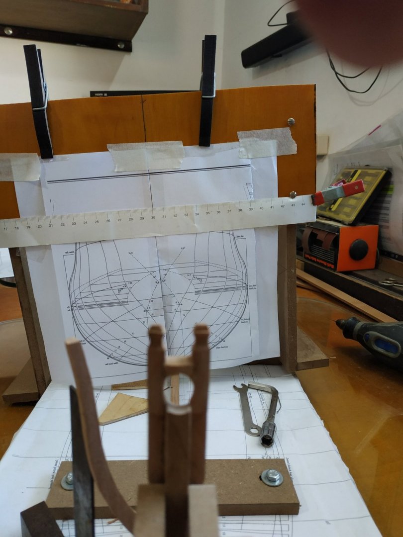


-
Swan-Class Sloop by Stuglo - FINISHED - 1:48
stuglo replied to stuglo's topic in - Build logs for subjects built 1751 - 1800

-
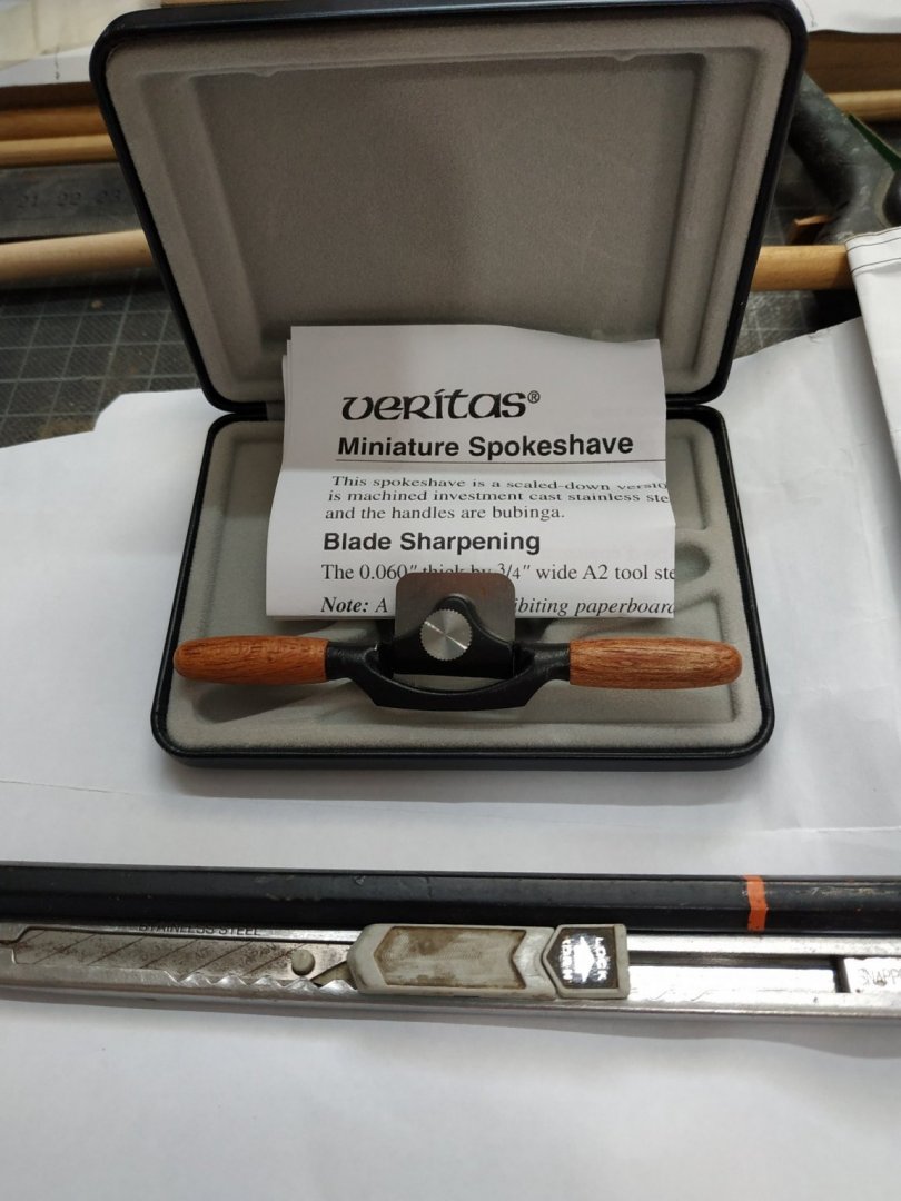
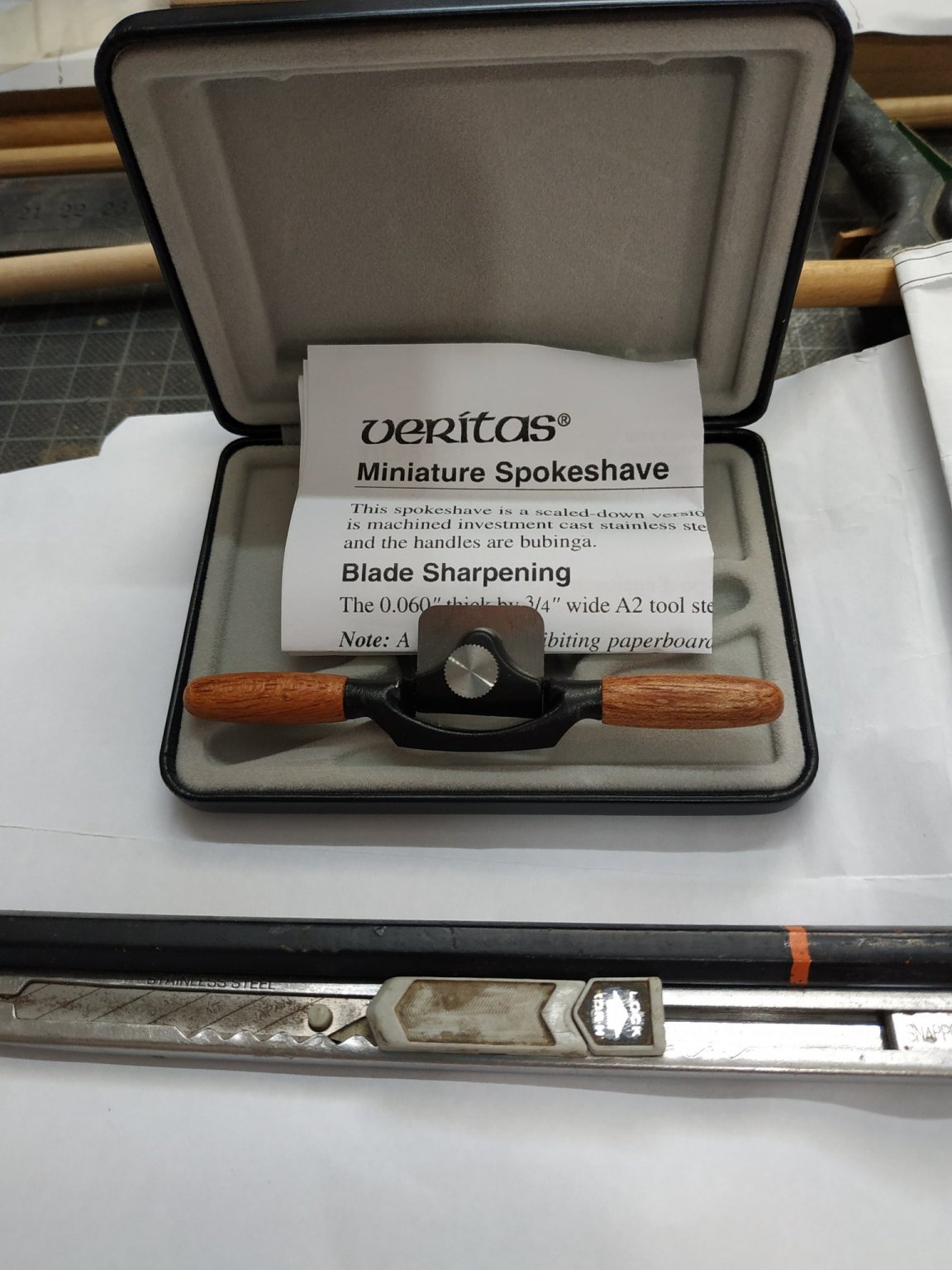
Thanks to all, especially the advice to epoxy handles. I have the next size up, but at 10in no suitable.I suppose like a lot of tools, they will be in a draw until suddenly I remember and it will be a beloved solution to a problem.
-
Saw on Kevin Kenny video - so bought it. An addition to miniature wood planes, It works.
-
Swan-Class Sloop by Stuglo - FINISHED - 1:48
stuglo replied to stuglo's topic in - Build logs for subjects built 1751 - 1800
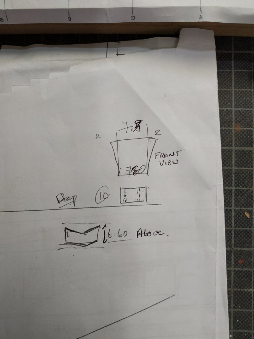
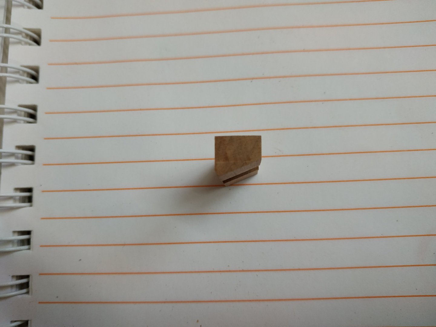
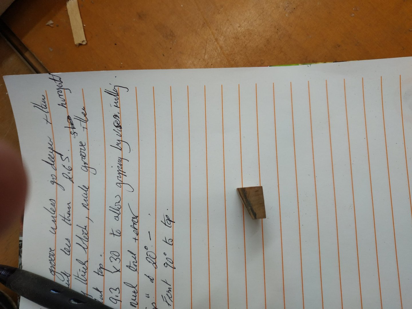
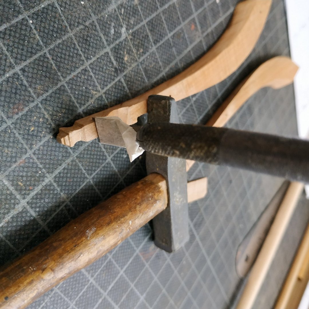
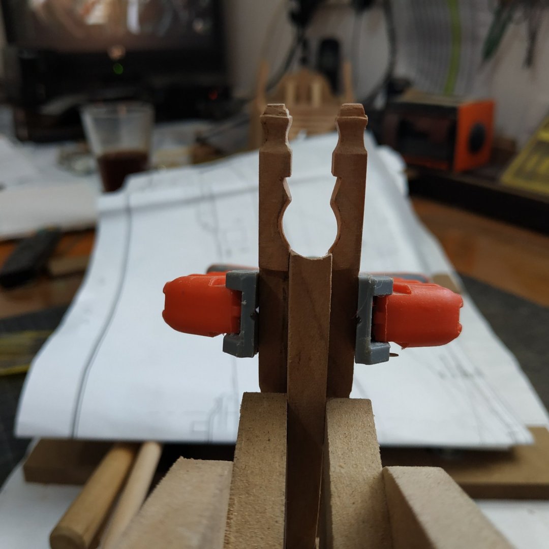
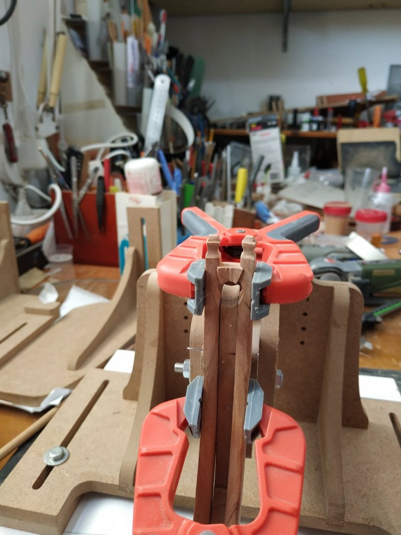
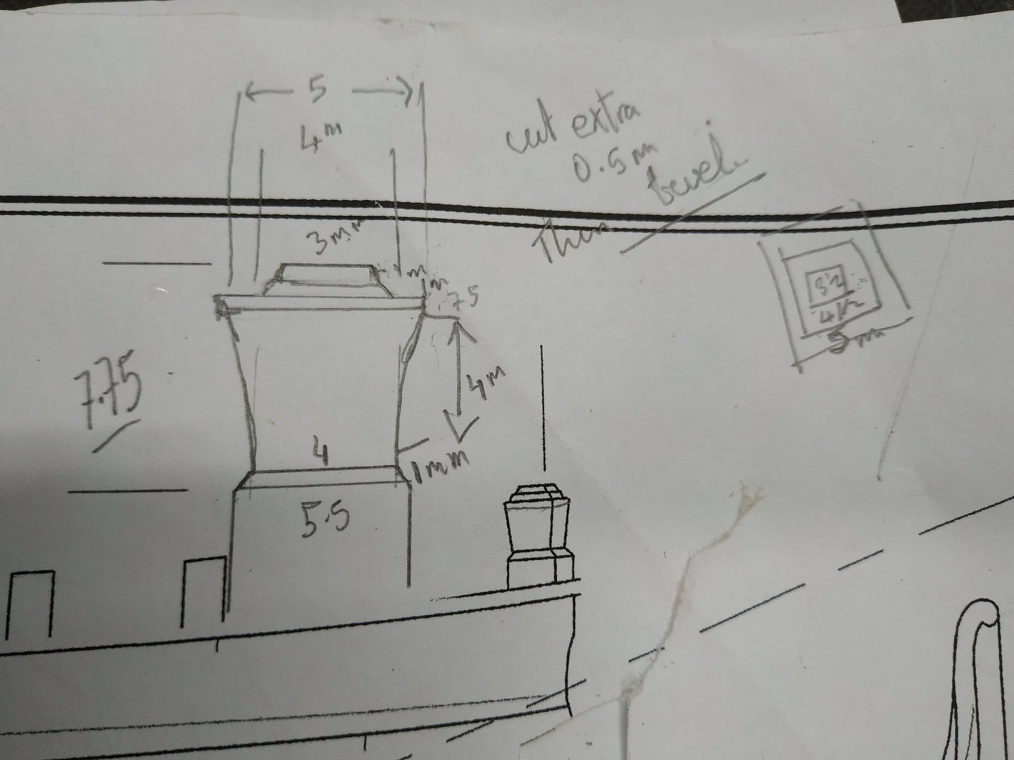
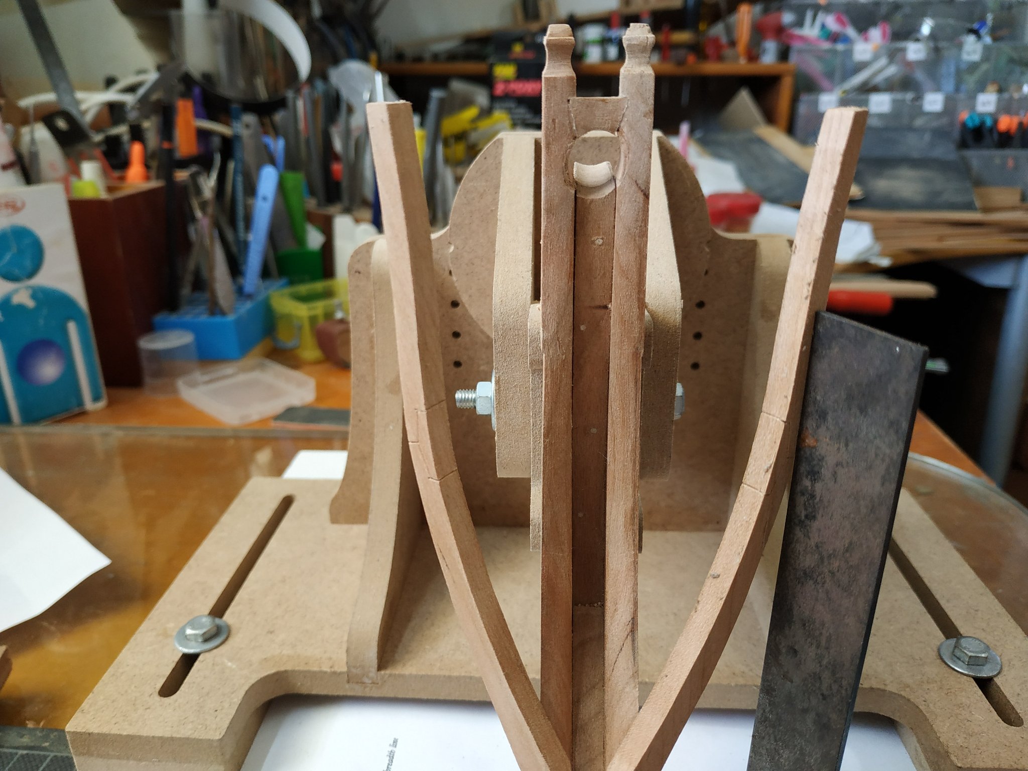
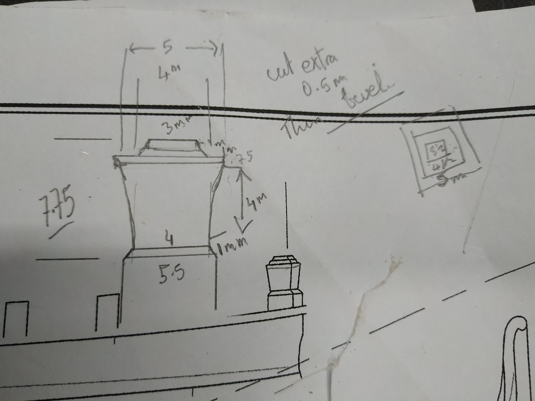
I suppose most of us like/need drawing the task at hand by way of deconstructing or reverse engineering and so understand what to do and visualise the result. I use the numbers, if only approximate, to help ,especially drawing larger scale to fill in the missing information (usually that I missed or forget). Given the front minimum thickness of chock, the aprox. angle 20, I can see the aft thickness. Yesterday's failed trial with sloping groove set me thinking to different approach. Abandoning the 6.36 block, I took one 9.3 X30X30, made the groove horizontal, across grain, and the, turning the block over and slanting flat underside (will be upper side ) to 20angle, milled this horizontal, so the groove (with its uniform depth and parallel sides) now becomes a 20 deg. slope. Front and back are now sanded to 90deg to top. The depth of the piece is now sawed in half. The second half can now be placed upturned spot glued a sides, forming a squared piece for easier working. The extra depth is important to allow for the "wing" effect (as seen from above) While this is drying, return to groove of timbers, clamp in place and with greater care and using the sliding sanding stick, form them more accurately. Removing the timbers again, lay on plan and mark high point of the underside of uppermost rail- the second line 11.5 below top of timber. This is the upper mortise line. HORIZONTAL -90deg to timber. It is on the INNER aspect of timber. According to Kevin 2mm deep. I commit to a chisel at last. Masking tape to set depth of cut. Tap Tap Tap with small hammer. IT WORKS. Terrified I will decapitate the head but its cross grain. More confident, trapping the piece with fingers (behind) I push from lip of grove, angled slightly downwards , towards cut and remove slivers until clear to base of mortise cut. Seen from front or back, the result is a right -angled triangular gap. Treat the other side, and when held together they become an isosceles triangle. Again, the point of the angle is the upper lip of the groove. Very satisfying. The chisel blade prevents the convex that tends with sanding small pieces by hand. Back to the chock. The (temporarily) combined piece can sit flat and the diagram in TFFM of the view from above can be transferred (traced) Note again the wing shape. Overall depth requires at least 6.6mm. The pieced is shaped with the wings overlong. The two piece are now seperated. The flat top is thinned slightly so the thinnest part above the groove (hopefully the centre) is 2.65mm Now for the fun. The with of the stem at mortise is 7.8mm Each side the upper mortise is 2mm deep, giving total 9.8mm The lower end is 0.0 Lucky with chisel already, but I won't push it, I use the hand band sander to make the bevel by stages -parallel fore-aft sloping down. Firstly with the timbers separately on the work table to check angles and fit, then offered to them when clamped to the stem until touch by touch, the fit. When sure and satisfied, glue. To misquote TFFM and Winston Churchill "Never in the field of ship modelling has so such time and and so much effort been to produce a piece so small" (Not true of course)
-
Swan-Class Sloop by Stuglo - FINISHED - 1:48
stuglo replied to stuglo's topic in - Build logs for subjects built 1751 - 1800
7th oct. Not posted yesterday because after 4 or 5 hours of thinking , planning and trying to understand the complexity of the mortise and bridging chock, I had little to show. TFFM suggested earlier the making and use of a sanding cylinder riding up and down a rod extending to the keel (station 3)such that it forms the correct angle to form the slope of the stem top. Remembering the bowsprit is 9.8mm , the top of stem , inner timbers and bridging chock make up quadrants to encircle this. While clamped to stem mark lower level of this groove on inner aspect of each timber where it meets upper lip of stem (it slopes).decided to start on the chock.Remove parts and just above this line , start making the grove. I used a 6mm round file to start then enlarged with sanding drum-keeping to the angle and margin of the slope .The depth suggested is about 1.55, leaving ,in my case,4.0 of the timber at its narrowest. Reassemble onto stem then use the sanding stick. *I overdid this, and a small sliver was left gluing overnight as the resulting hole for the bowsprit would have been too large . While waiting for this, and having the grooving tools to hand I thought to start the chock. A small block of 6.36 is suggested. The same groove is made at the angle of the bowsprit slope (as I will now call it), which is also the slope of the underside of the chock going aft. This I tried to do but the result was a fan shape looking backwards because these slopes didn't match. Have to sleep on it -
Having just ordered your Vol4 Swan TFFM and paid nearly $50 dollars shipping, perhaps you can consider producing the book as an e-book (if you still have rights.).I love possessing and handling books, but postage is prohibitive. At least with the 3D rendering, I exercise going back and forth to my computer. (my main exercise in covid lockdown)
-
Swan-Class Sloop by Stuglo - FINISHED - 1:48
stuglo replied to stuglo's topic in - Build logs for subjects built 1751 - 1800
Thank you -
Swan-Class Sloop by Stuglo - FINISHED - 1:48
stuglo replied to stuglo's topic in - Build logs for subjects built 1751 - 1800
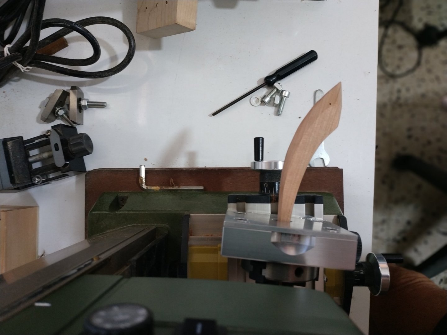
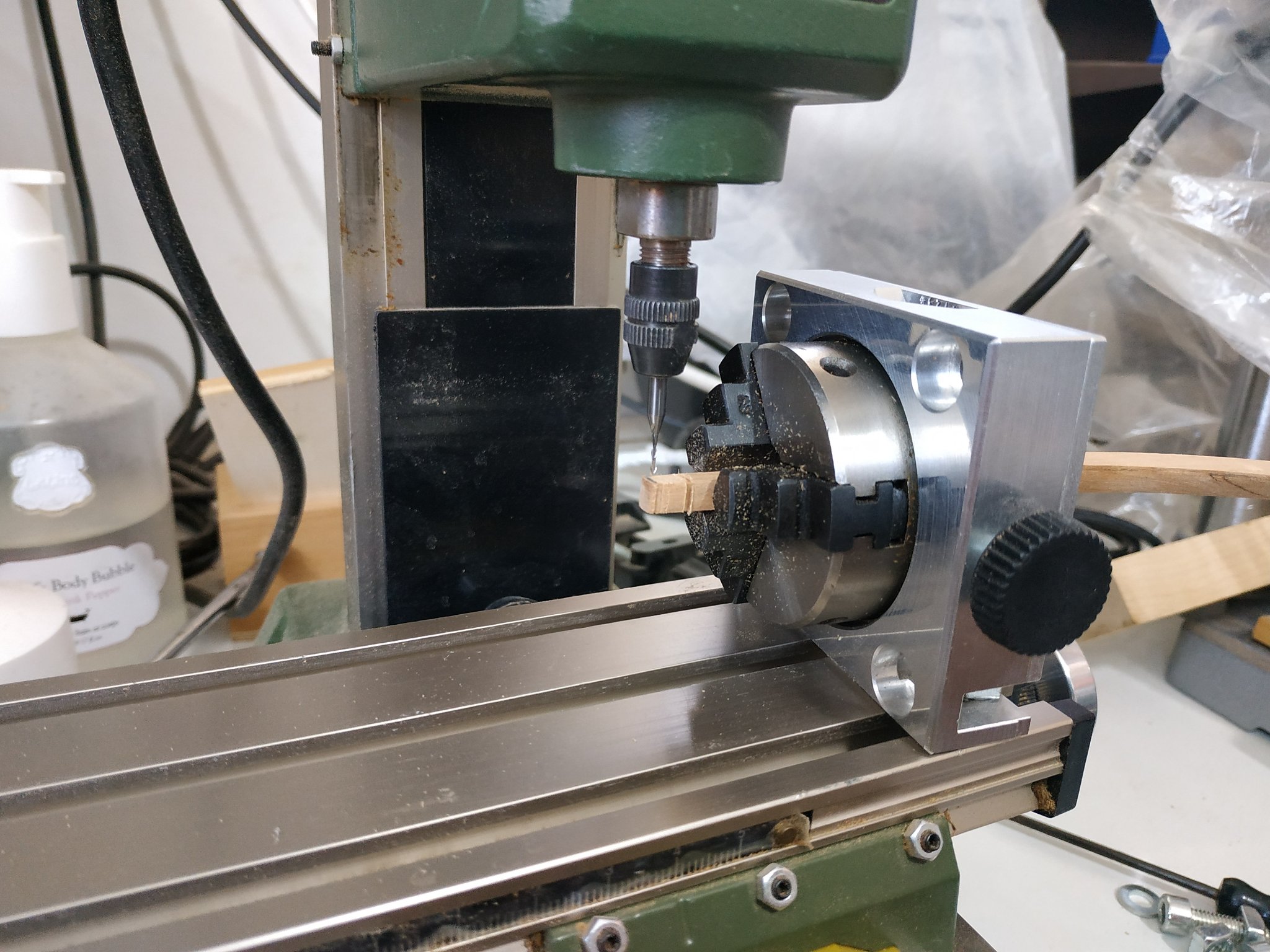
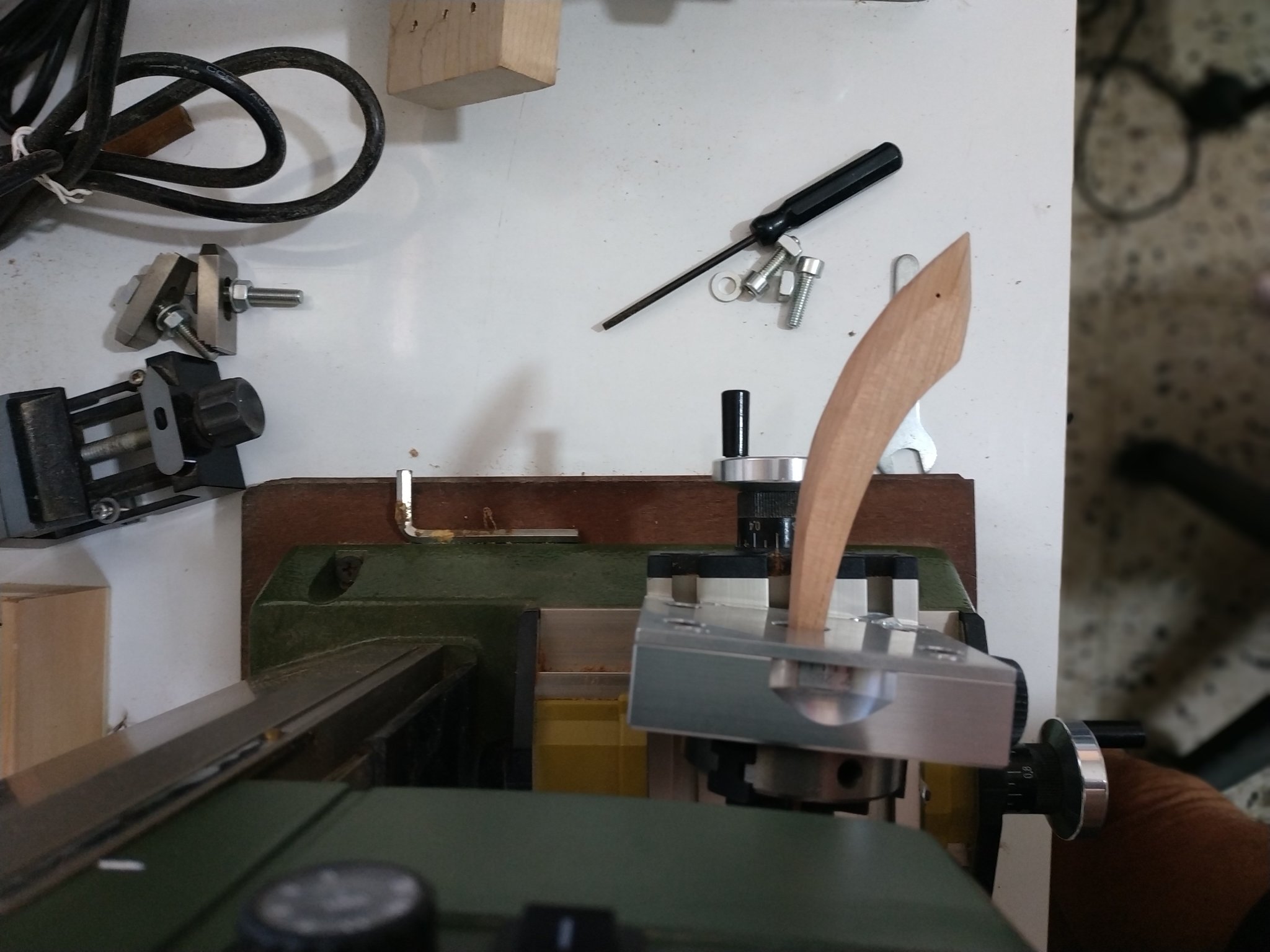
In 1980 I was involved in medically examining English athletes for the Moscow Olympics (which they subsequently boycotted). This is where I first learned about the importance of visualization to perfect physical activities. (when I was younger these were called fantasies). The relevance to those model building will be apparent when I tell you I awake in the middle of the night planning how to do something. This was especially true when considering the head of the timberheads. The simple method of shallow saw cut and shaping is prevented by the parallelogram effect and backward slope. In past models I must have missed this or fudged it. Checked out Kevin's video -at first this upset me because my small table saw's blade is of fixed height. The middle one, blade to thick and not as yet built a sled. Fortunately he later discards this method (Phew!!!). At least reminded me to use some trial pieces. The medium saw was inaccurate in at least one of the dimensions required then-lightbulb moment- my dividing attachment for the proxxon milling. Used vertically, it will rotate the head to compensate for the parallelogram. Not enough, as about to return to some free hand work, I thought -what if I slightly rotate the attachment to match the slope of the stem. The narrowing of the piece as is rises upwards is not a problem over such a short distance. Trial piece not so successful but I can see this is a solution. Drawing at a larger scale, calculating the spacing and depth of cuts and using 1mm bit. I commit myself. Just remember to double check which wheel you need to turn and which direction. Eyeball the end of the piece to check they are horizontal to the table. Working each side, firstly fore aspect, I removed 1mm down at depth 0.3mm, another 1mm at depth 0.5, 1mm at .2mm and final line a further 4mm at depth 0.5. Rotate piece within the attachment 180deg. Starting from top, this first past should be about 0.5mm further down- fitting the slope to aft of stem. Repeat previous steps. Now rotate 90deg and releasing the holding nuts, the attachment can be angled to follow the slope. Double check the direction of the angle allows it to run parallel and repeat the same sequence of cuts. Rotate 180deg. and change direction of holding attachment to opposite and again follow line of slope. Its sounds complicated reading this but it is quite simple. I took Kevin's idea and used the mini proxxon sander P13 with barrel head and it shapes the widest gap quite well. I was less successful with the mini files and sanding. Not completely satisfied . Maybe later on remove top bit and refashion. The problem is seeing the 3D and the great craftsman on this site makes me want better for myself.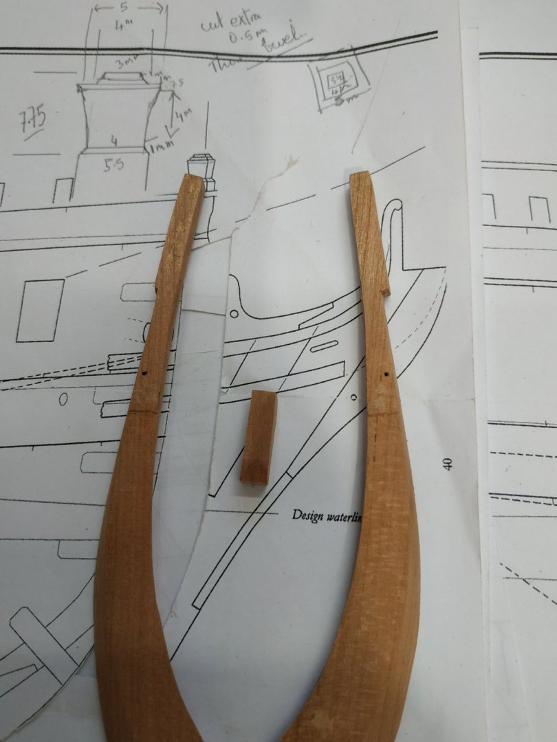

- 475 replies
-
- 12
-

-
Swan-Class Sloop by Stuglo - FINISHED - 1:48
stuglo replied to stuglo's topic in - Build logs for subjects built 1751 - 1800
Thanks for the tip. Just skimmed Remcoe log - this is really setting the bar high, nevertheless I will persevere -
Swan-Class Sloop by Stuglo - FINISHED - 1:48
stuglo replied to stuglo's topic in - Build logs for subjects built 1751 - 1800
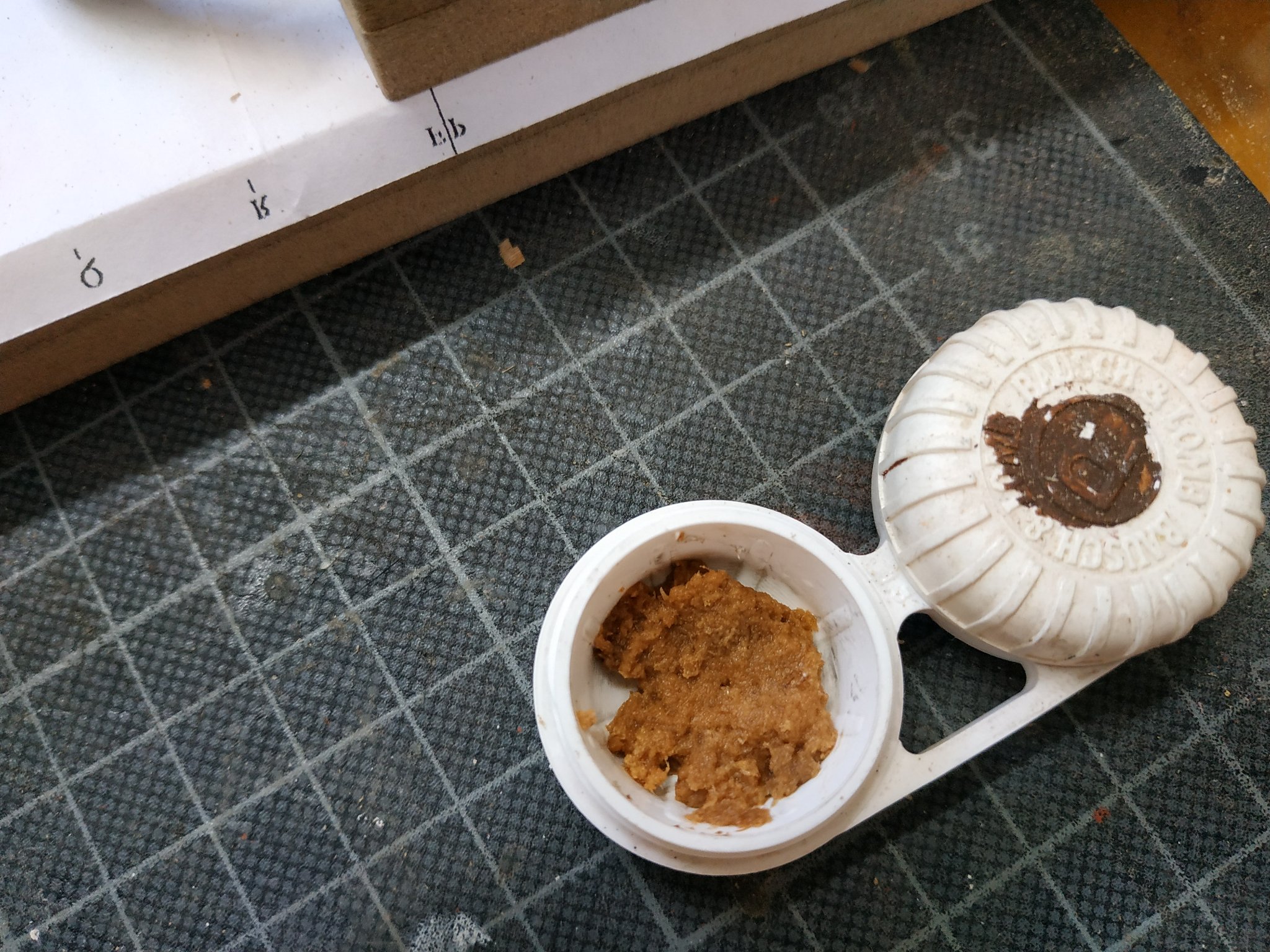
Moving on to the air spaces. Almost made mistake as the text says make it BELOW the hawse hole but the drawing seems to me to show those above. The amount to be removed is a thickness of 0.4mm. Allowance must be made for the gradient created when the piece was previously thinned . Chisel is again the suggested method but I will again postpone this until I acquire the necessary expertise and mess up a piece that I have not invested so much time. Set up for milling with a thin wedge to compensate for the height difference. The starting line is marked by small "v" on plan. Start the milling just below this so that later a 45deg downward sloping cut can be made with a blade. I use a small Proxxon MF70. I have limited experience but it seems adequate for my needs. The shape of the part requires repositioning one of the clamps. This done, I lowered my bit the 0.4 mm and switched on without realising I hadn't needed to raise it to re-site the clamp. Fortunately I hadn't touched any directional wheel and the bit was only 2mm. Must have been the evil-eye of the chisel gods, Finished the job, putty mix with sawdust and watery PVA and almost invisible repair. (It's in a place that will be hidden but I know). 2 loose holes for pinning pair of pieces in place. One already in foot, the other above the air space line. For accuracy use drill press (90deg) and holding one piece correctly positioned, the hole will guide the drill bit as 90deg through the stem. Except I hadn't allowed for the thinness of the overlap and it simply missed the stem. Redo near fore edge. The extra hole get the putty treatment. **Two stupid mistakes in quick succession require immediate cessation of building activities. Usually lack of concentration or bad luck- doesn't matter. I remember reading a book on playing bridge by S.J.Simon many years ago- if things go wrong, get up and walk away. Tomorrow is another day. I'm too embarrassed to post any pictures. -
Swan-Class Sloop by Stuglo - FINISHED - 1:48
stuglo replied to stuglo's topic in - Build logs for subjects built 1751 - 1800
The missing stuff is on Some Other Ship forum, under stuglo Oneidin followed "Oneida"-Lumberyard which I printed up in 2011as ref- http://modelshipworld.com/phpBB2/viewtopic.php?=8033&postdays-0&postorder=asc&&start=540 I'm sure you can find this more simply. I also referred to Niagara and Eagle build logs. DON'T give up It's like forgetting a word-sometimes when forcing fails, get on and do something else. Then you get the lightbulb moment (In my case usually at 3 am). Another thing -don't be shy to ask -the one thing better than the satisfaction of gaining knowledge is it's sharing. -
Swan-Class Sloop by Stuglo - FINISHED - 1:48
stuglo replied to stuglo's topic in - Build logs for subjects built 1751 - 1800
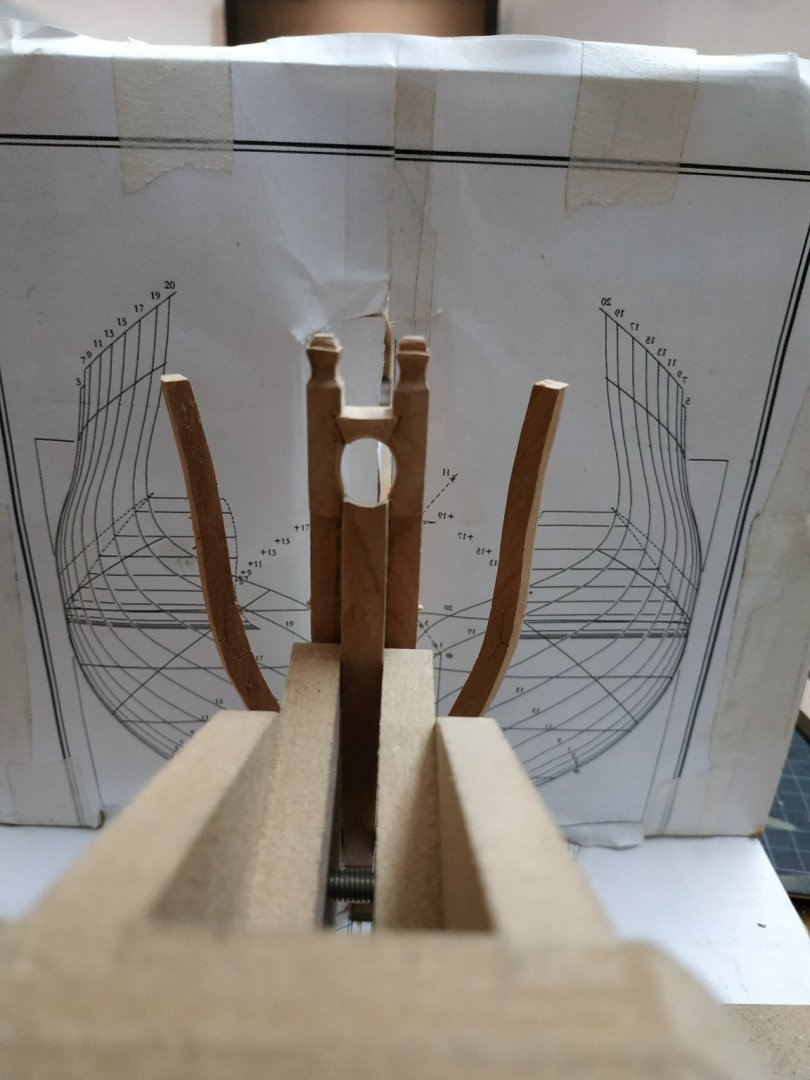
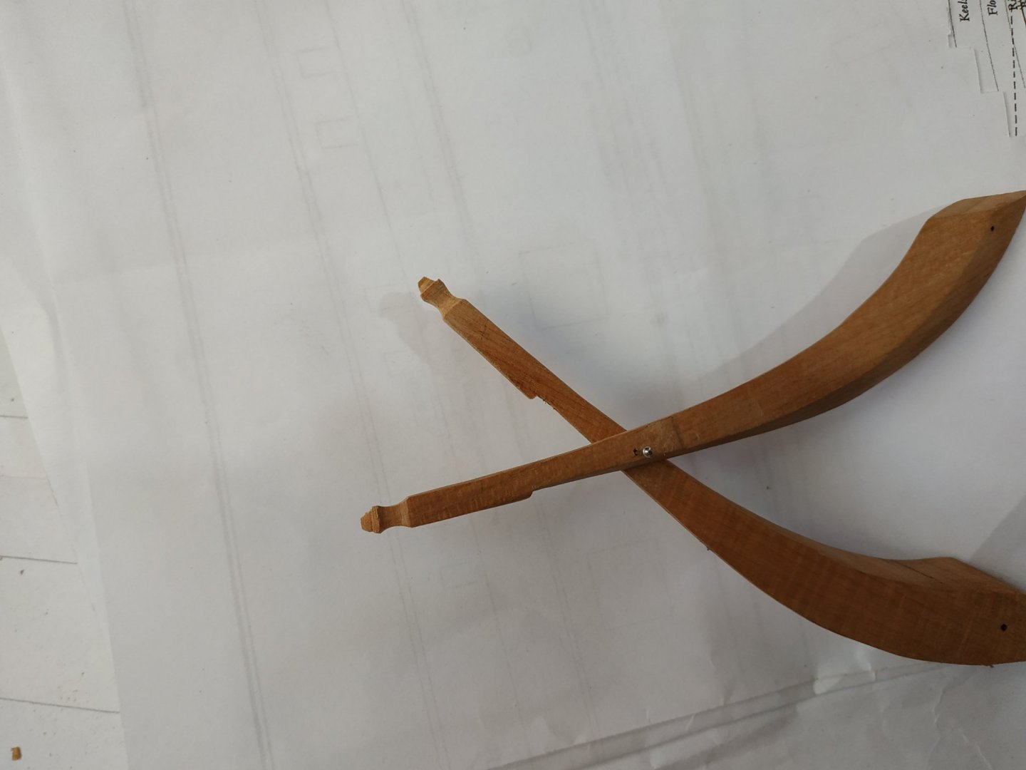
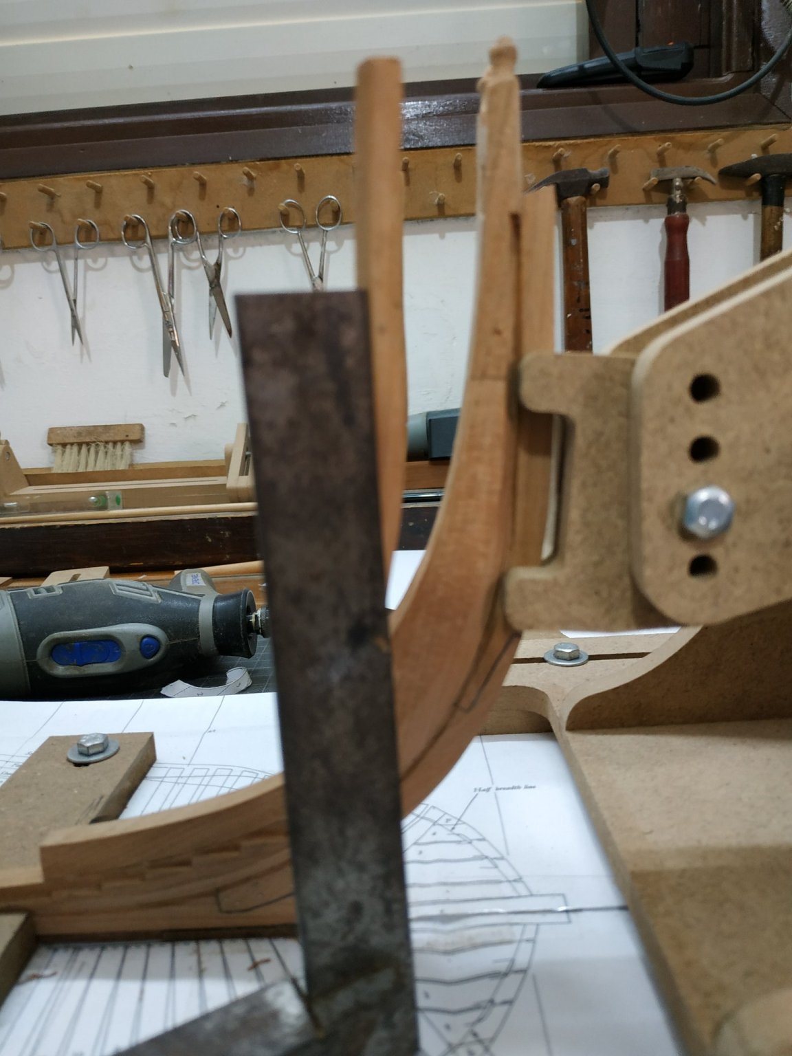
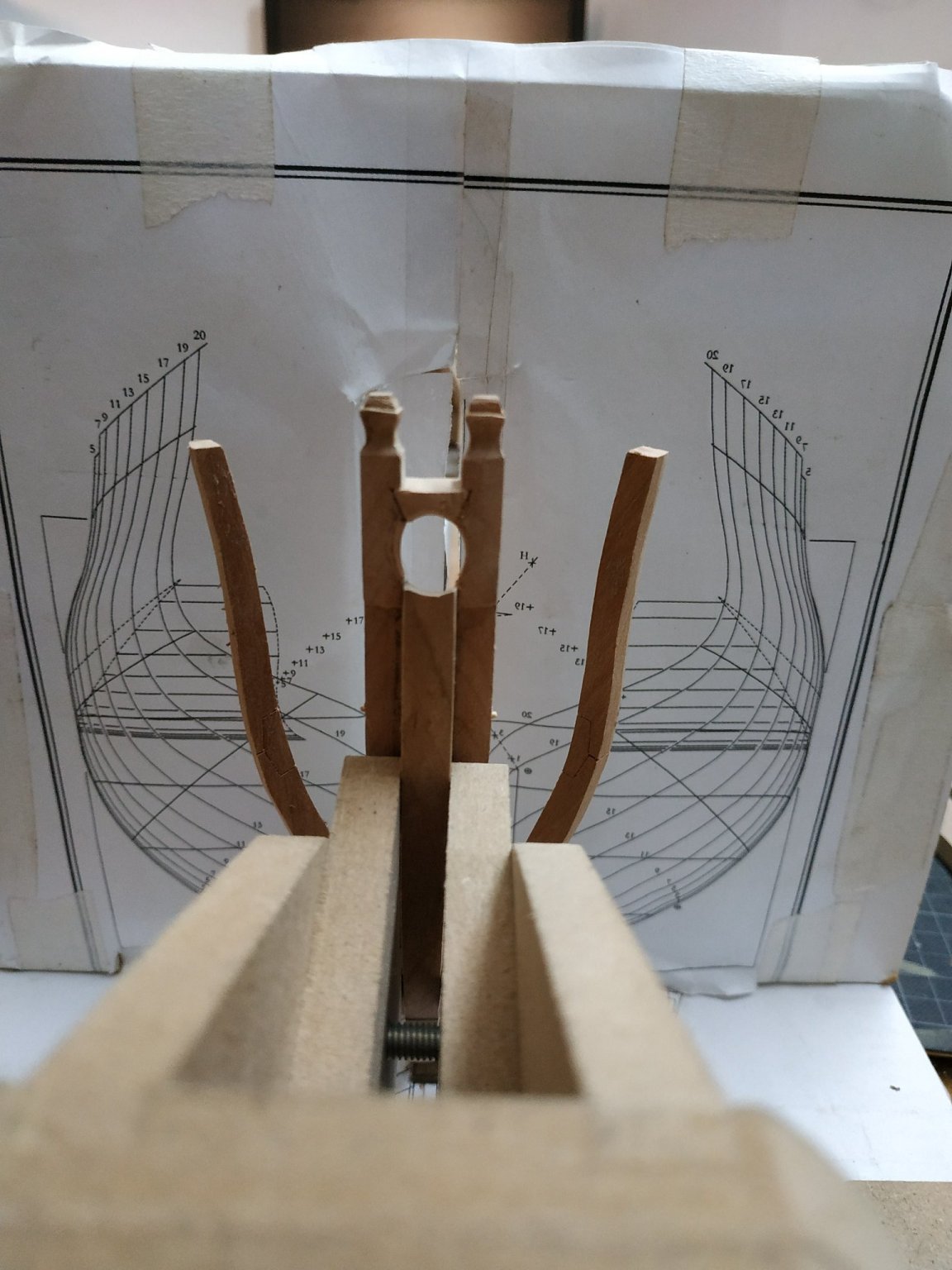
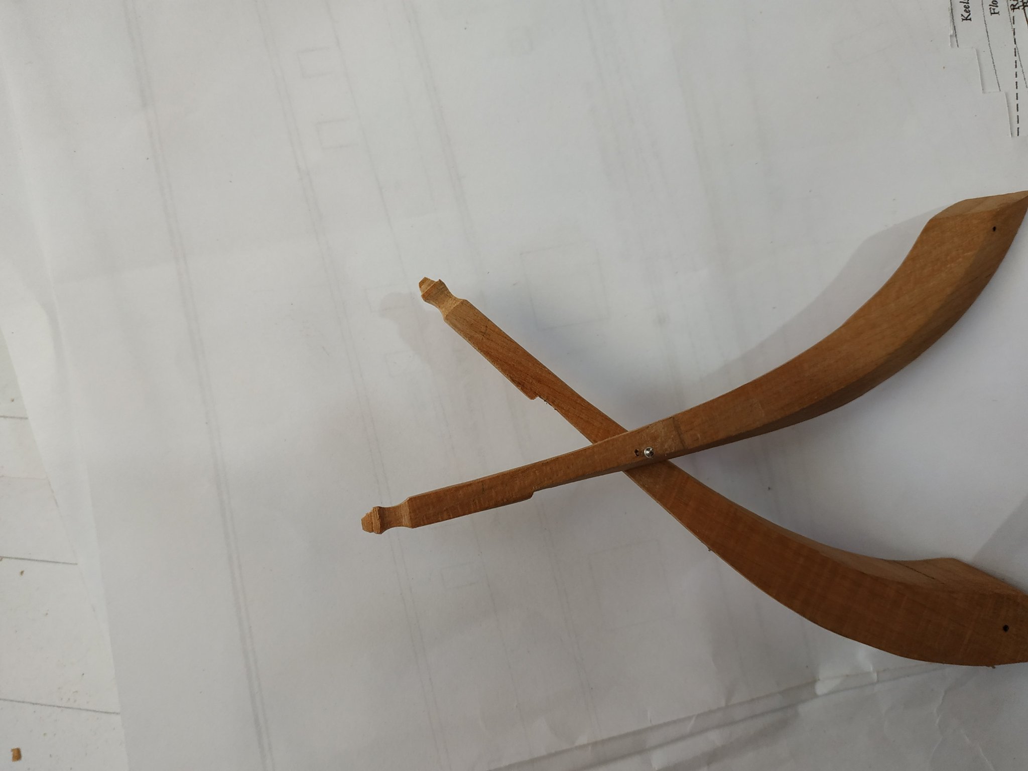
Previous post on modifying the Building Slip. I've been singing its praises but nothing is perfect (except my wife of course) . Apart from a stable bridge I've changed the keel clamps to allow access to breadth plan. Return to timberheads. Need to bevel forward faces .Keep in mind how the planks lie to ensure remove right side- then mark it.I have no confidence in my ability with a chisel (as recommended in TFFM) but use combination of table belt sander, hand held belt sander, small sanding block and a final knife scaping to flatten the curved surface that my sanding tends to give. Note- suggests a narrow margin is left (illustrated in book).There is another (smaller) bevel on the opposite-inboard- side. Check multiple times that the wood you propose to remove coincides with direction of future planking.Looking under the "foot" should give a rhomboid shape. TFFM then speake of a small step (1.3mm) that suggests can be postponed. Good, because I don't understand what is to be done. Referring to the 3D, I see something, but am not sure if this is it. The next step looks complicated , delicate and slow- and the Bosun suggests I need to fix the toilet cistern -oh s***. As the pair of timberheads are frequently offered up to the stem, a pin is loosely inserted near base at right angles, with the stem between them .

- 475 replies
-
- 14
-
-
Swan-Class Sloop by Stuglo - FINISHED - 1:48
stuglo replied to stuglo's topic in - Build logs for subjects built 1751 - 1800
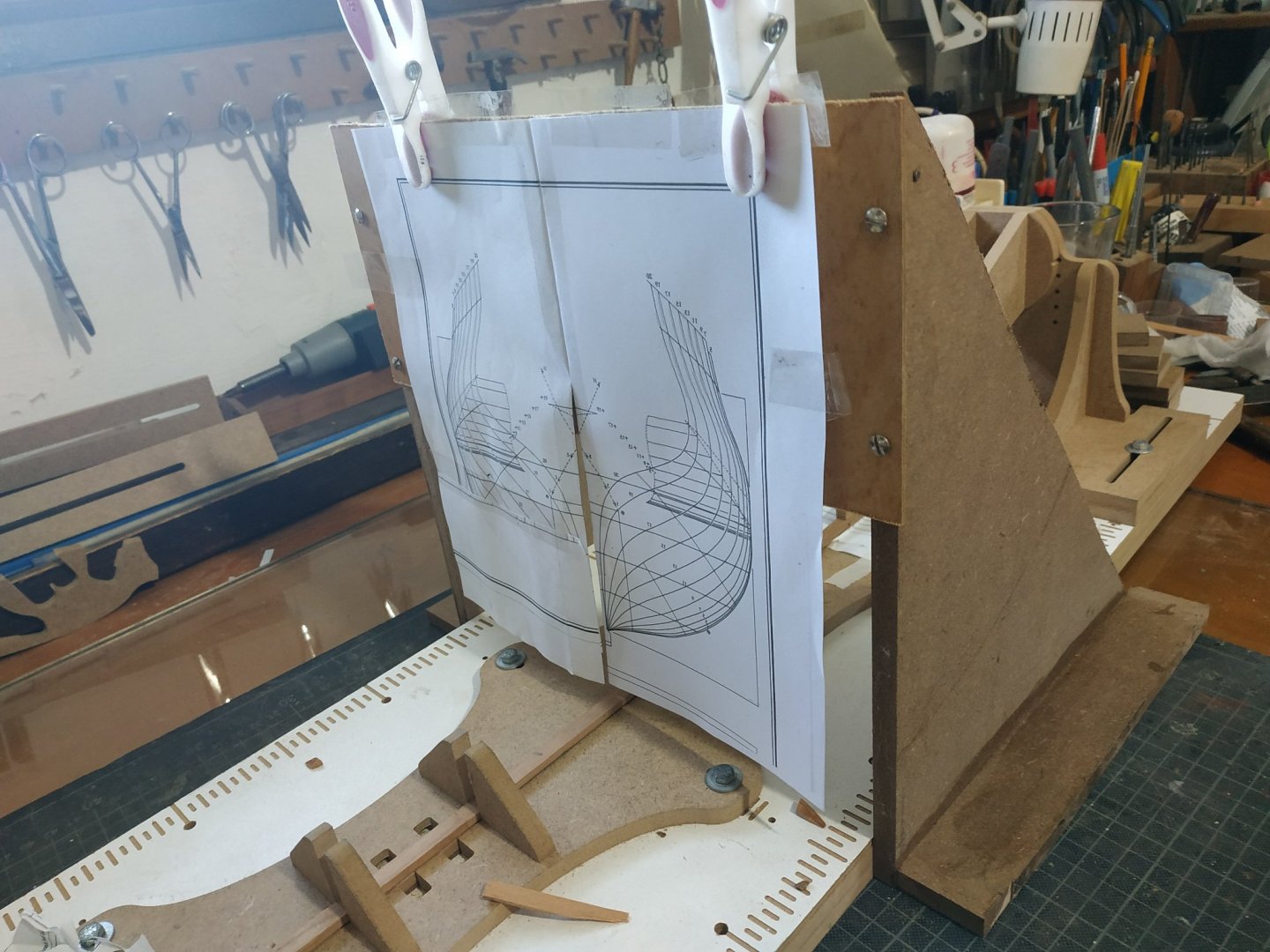
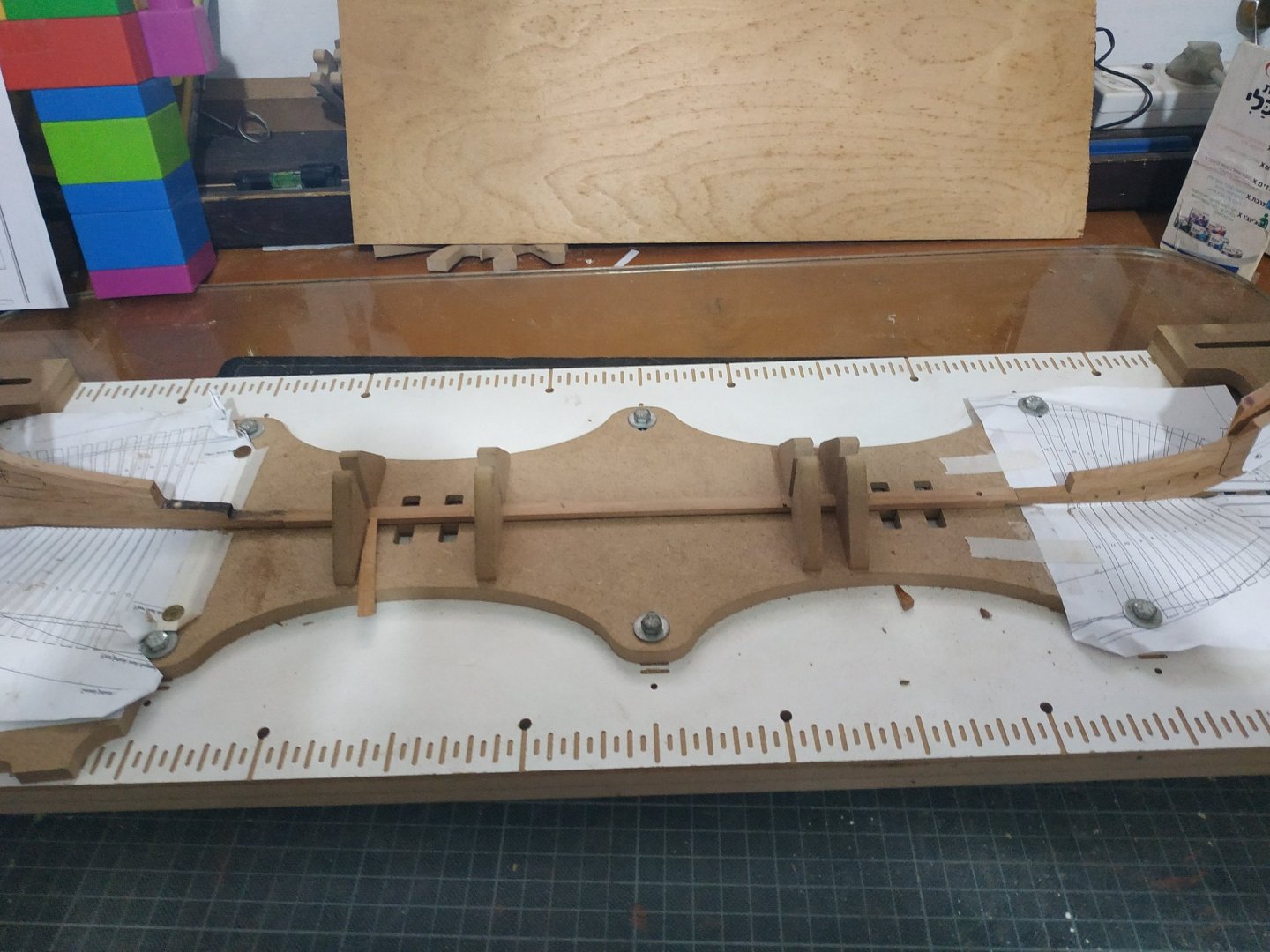
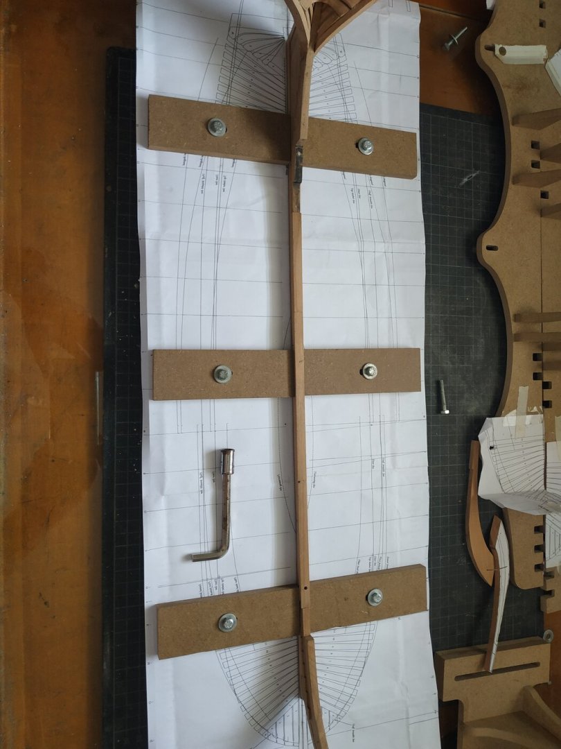
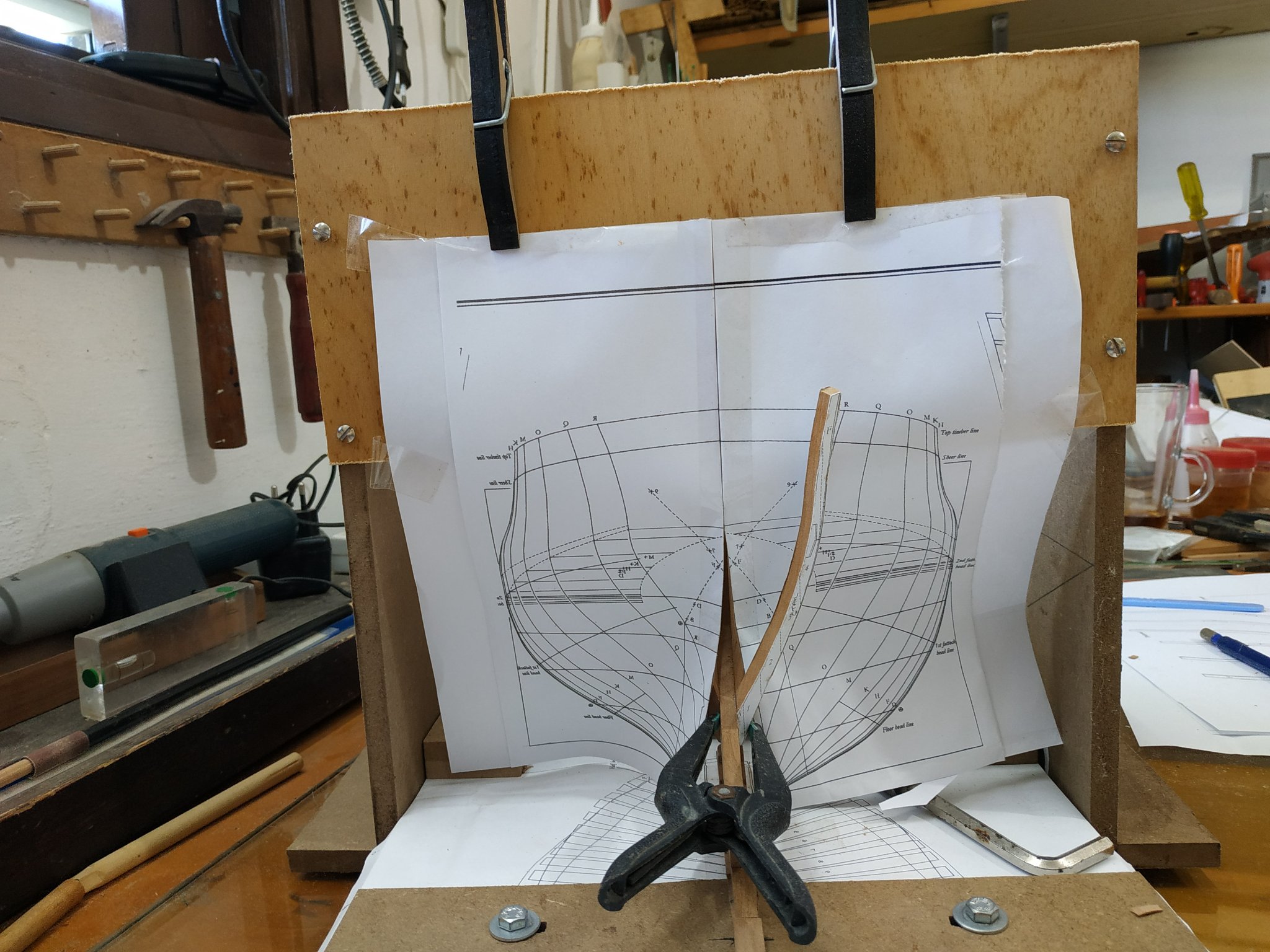
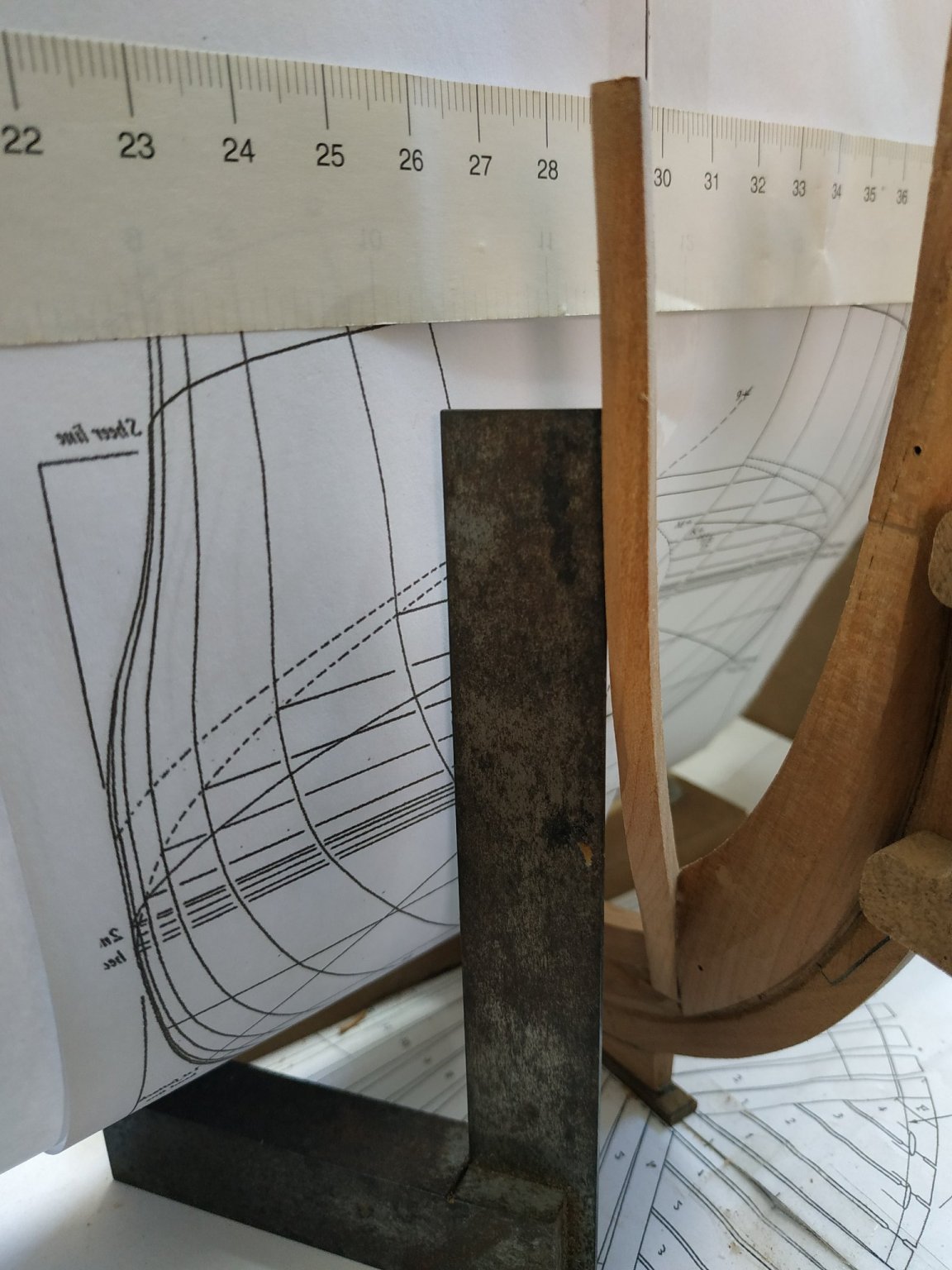
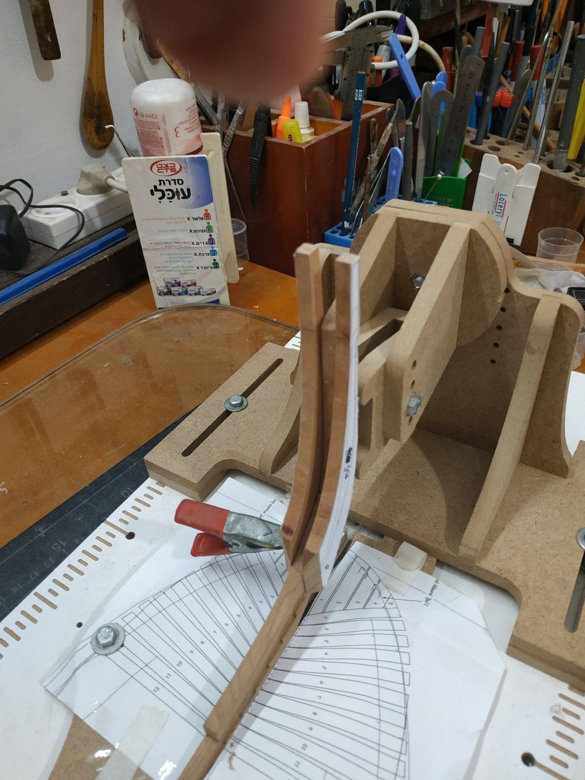
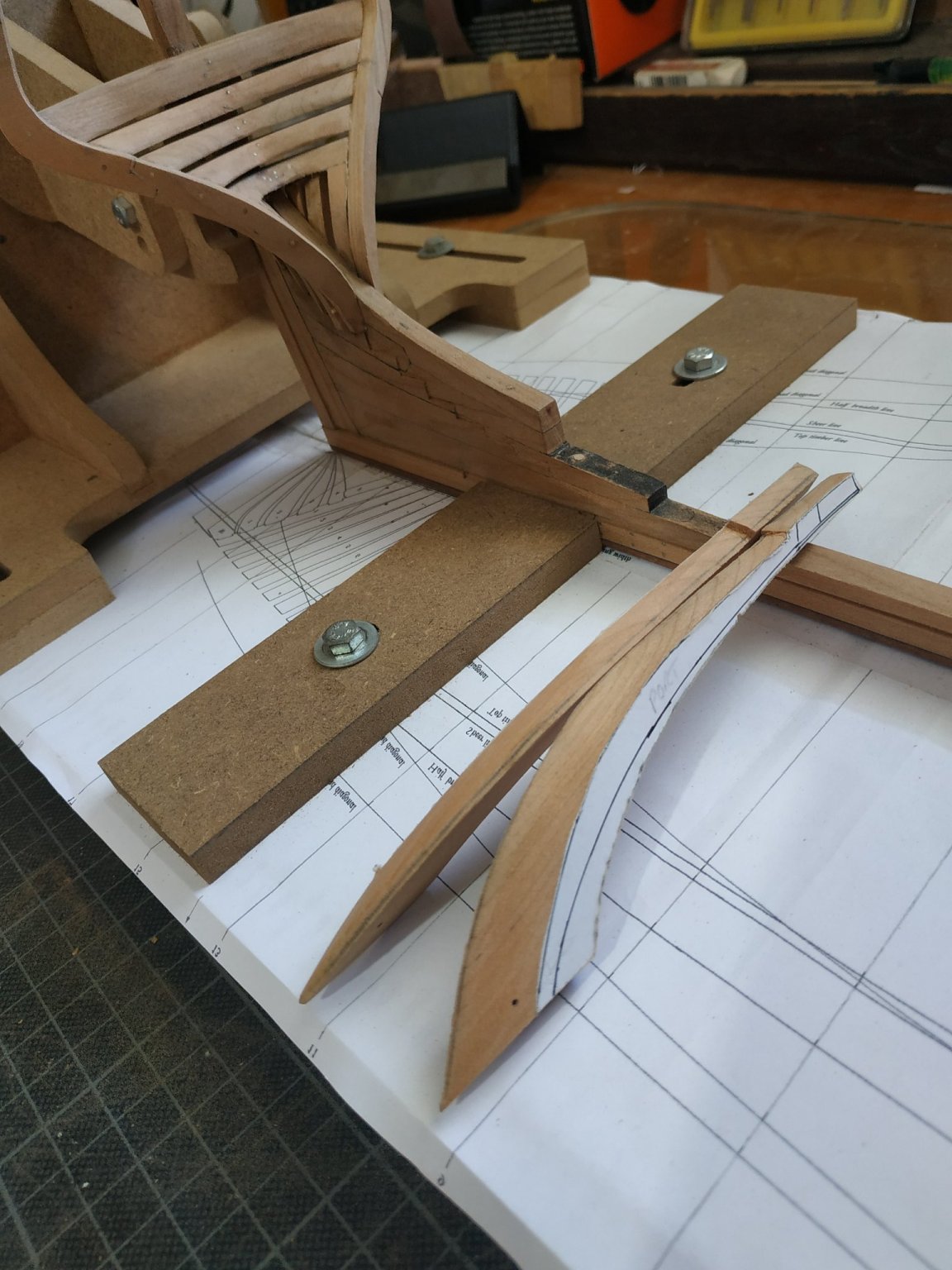
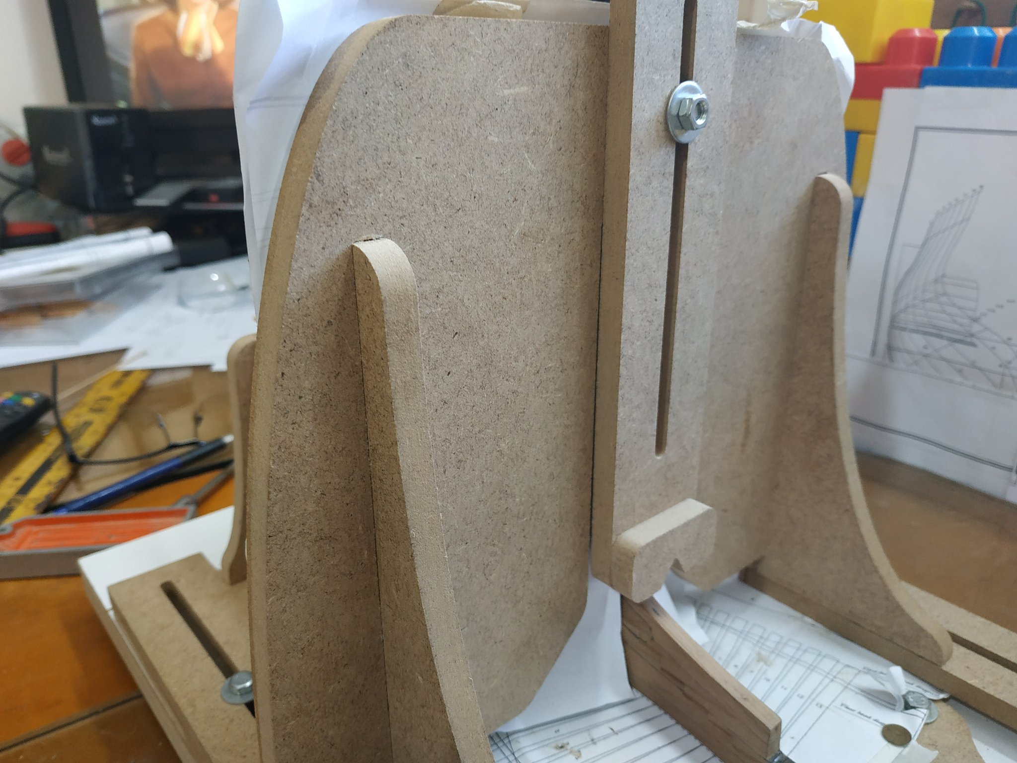
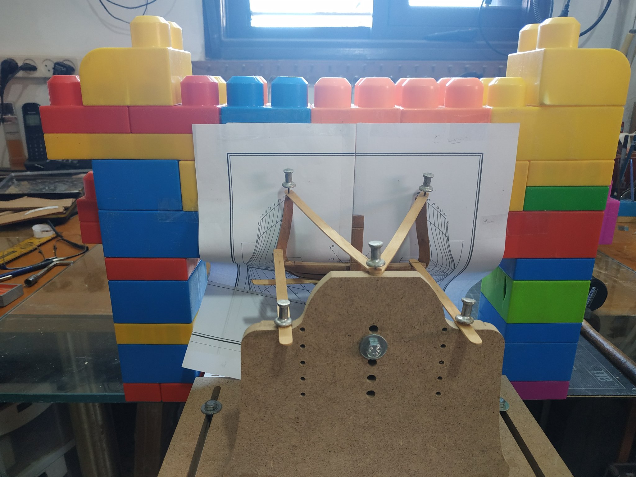
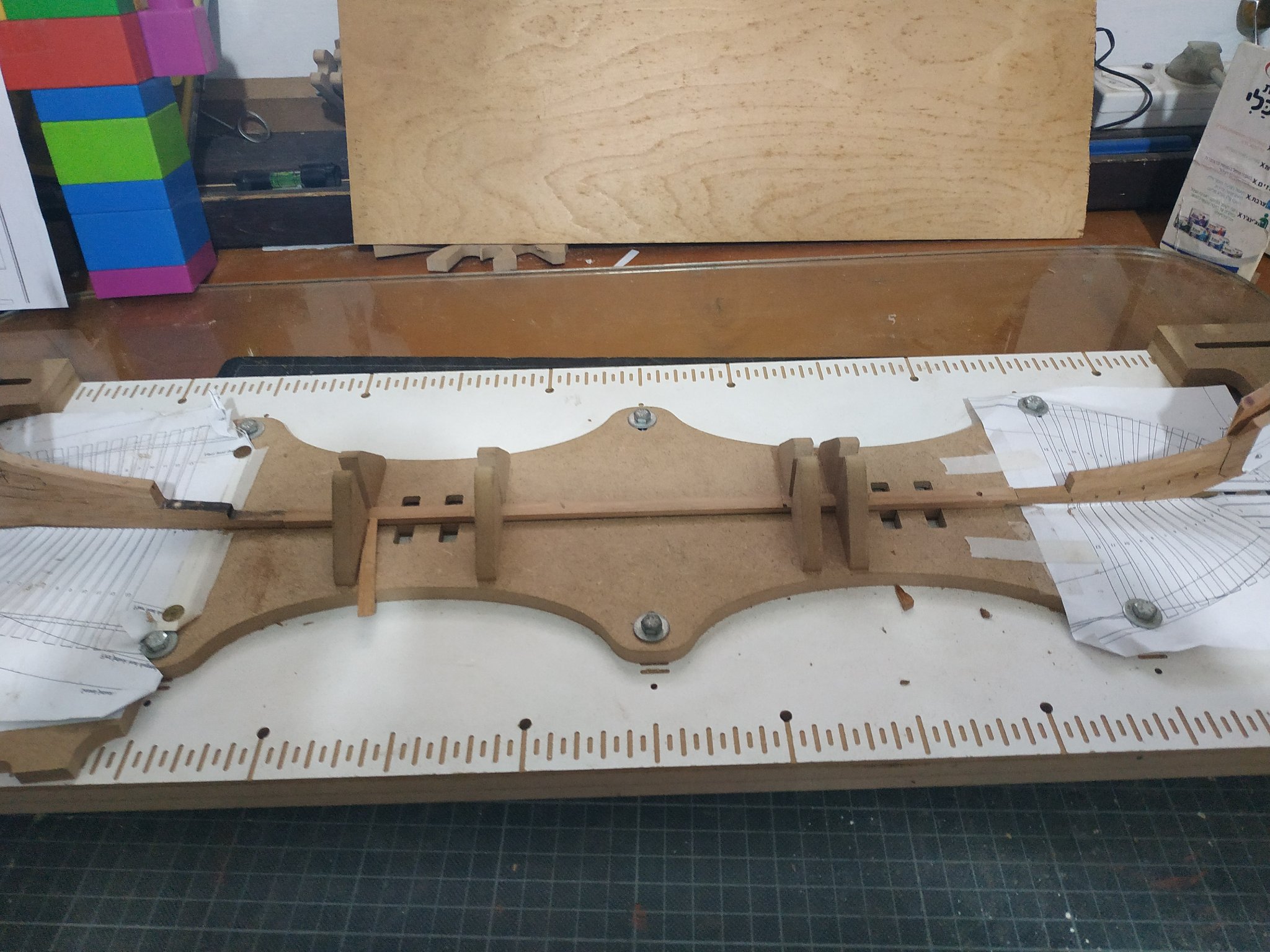
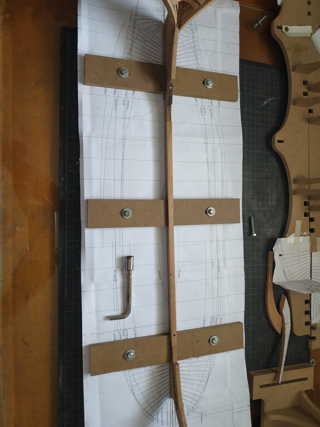
2 sept. I hope to continue posting here . I have been using the Hobbyzone Professional Building Slip for my swan build. Not cheap but very versatile. However come across 2 problems. The vertical holder for the body plan does not allow it to be set against the aft cant arms . My quick fix with large building blocks is temporary as the little grandchildren need them back. A stable "bridge" whereby the height of plan can be adjusted was built with some MDF leftovers. With the keel "clamps" as supplied laying the breadth plan on or under them severely limits viewing and alignment of cants and ribs. These have been temporarily exchanged for narrow substitutes.

- 475 replies
-
- 10
-
-
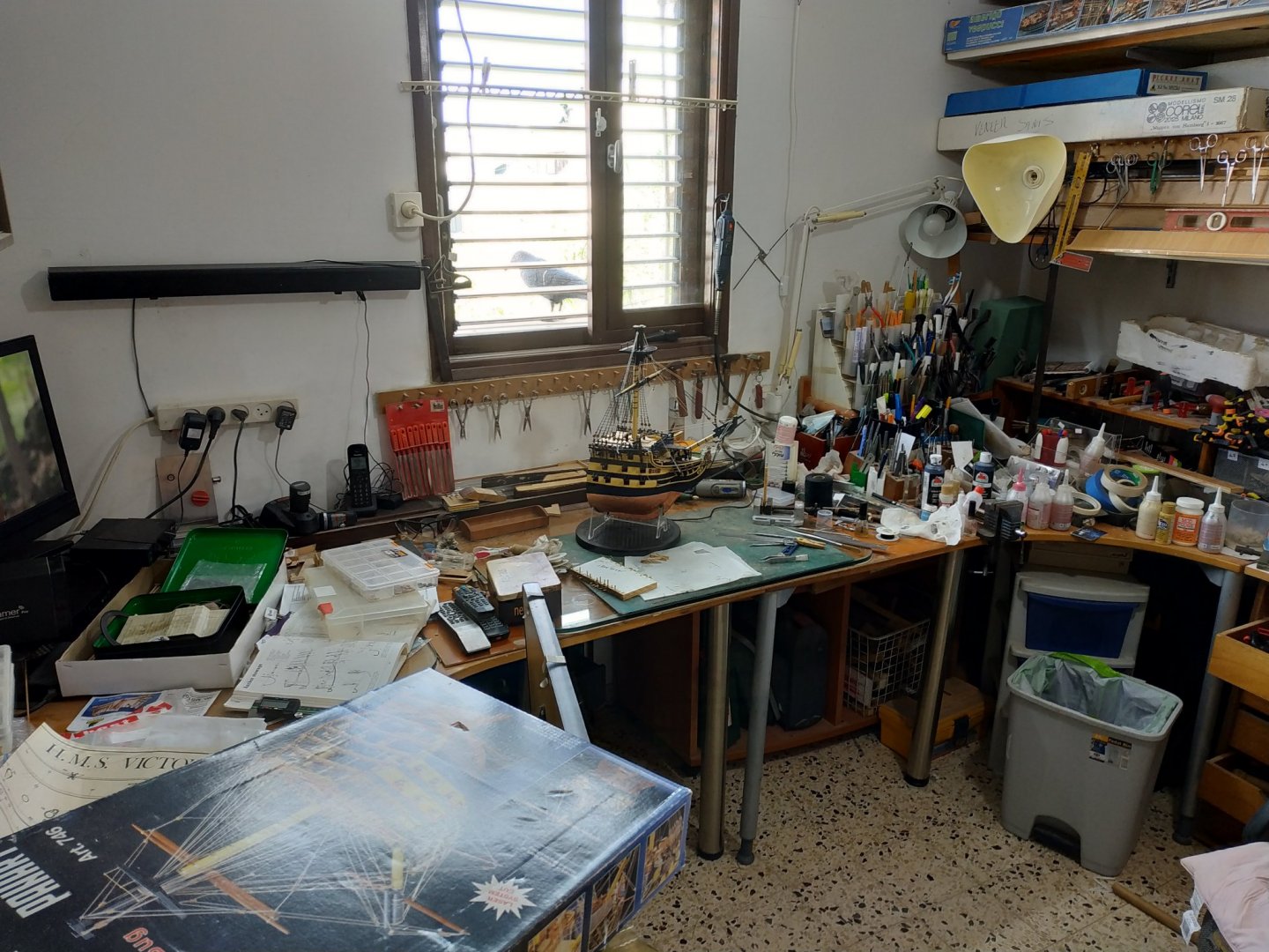
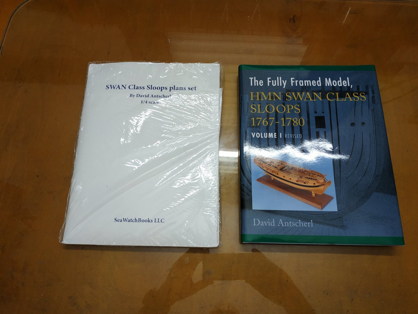
I was invited to share my blog which I started a few weeks ago on another site. I was undecided whether to start a blog as there are so many good ones already out there. What can I add? Maybe a perspective from someone with more enthusiasm than talent. I'm no artist-can't draw for toffee. But wood is forgiving and the final result can hide a lot of mistakes and botch ups. When I started building 30 years ago, there were few books, no forums and restricted number of kits, mainly european. I had a mentor/teacher/friend who started me with additional help from magazines, Ships in Scale. Kit-bashing was for an elite and I never heard of scratch. In these magazines several builders were so good that they had to be professional. Well, we have forums, massive of information and machine and tools not available not so long ago. I built the Onieda (lumberyard) beautiful wood and kit but very difficult for me to understand the building process and lost some enthusiasm. I gave up in the middle, built the Charles Morgan ,visiting the real ship, and returned to Oneida with renewed enthusiasm and guidance from a blog on the internet (2014) After several large builds (Diane and Agamemnon ) I deliberately built variety of "quickies". I then bought the Robert Hunt Practicum of the Hannah with wood from Lumberyard. A new level. I love books,and have over 40 printed and e-books. Reading another blog I discovered The Fully Framed Model,TFFM (thanks Canoe21). The idea of scratch took root. Visiting my friendly carpenter to buy a cheap off-cut to use as a display base for a soon to be completed model, I asked him if he has any wood, beside MDF, Pine or Ply that is used in cupboards these days. He showed me some planks of cherrywood that had stood unused for 10 years. I bought them for the price asked (very cheap) and now owned 450X15X3 cm of raw material that TFFM says should be enough. Over the last year, I purchased what seemed according to others, to be essential. Plans from Seawatch books, vol.2 TFFM, milling machine, a larger table saw, thickenessor (Proxxon) and Band Saw and spindle oscillating sander (together less than the cost of a weeks holiday that I cannot have in covid - time, as I told my wife). I still thought that more experience was necessary and purchased another semiscratch kit, Rattlesnake and ordered Alert. A sudden health issue and seeing how many years others took to build scratch, I took the plunge. I think Einstein said he stood on the shoulders of giants, I intend to stare under the armpits of other bloggers particularly video blog of Kevin Kenny and Dan Vardess and Trussben. Thank you. The foregoing is to encourage the "ordinary" hobbyist to realise it can be done and not be overawed. 18th Aug 2020. First clear decks from previous build. I tidy up between stages but generally work in chaos ( spare bedroom, wife keeps distance)
.thumb.jpg.3fdd37aef0d904f171f1f551a410d5d6.jpg)
- 475 replies
-
- 15
-
-
may I add words of praise. You efforts encourage me to move it up my wish list .
- 64 replies
-
- 2
-
-
- yamato
- deagostini
- (and 2 more)
-
Construction and Fitting of the English Man of War 1650-1850 by Peter Goodwin - ISBN 0-87021-016-5 - $25.00 HMN Swan Class 1767-1780 Vol 4 By Antscherl ISBN 978-0-9820579-8-8. - $15.00. (water damage top binding area) I see others are interested in these , but if the become available , I would buy them for possible delivery in UK
-
possibly interested in Amerigo vespucci. Could you estimate weight and shipping charges both within USA and to Israel
-
Just seen you last video Naparima. Thank you for this and the others (not seen them all yet). Much to learn from you, as I already have applied to my own build. Just keep going-stay well and safe
-
The" seats of ease" seem to have a lift up seat. ? Mixed crew? Good work


.jpg.f979e2de002e920494c5156139e72692.jpg)
