HOLIDAY DONATION DRIVE - SUPPORT MSW - DO YOUR PART TO KEEP THIS GREAT FORUM GOING! (Only 13 donations so far - C'mon guys!)
×


Mahuna
-
Posts
1,504 -
Joined
-
Last visited
Content Type
Profiles
Forums
Gallery
Events
Everything posted by Mahuna
-

Recommendations For A Good Milling Machine
Mahuna replied to Thistle17's topic in Modeling tools and Workshop Equipment
I will always vote for Sherline. They have several models, and I like the 5400 with the 12" base and resettable hand wheels. No matter what mill you go for, you should be aware that you'll spend as much (or more) on accessories. -
Superb! Love the photos with the watch for comparison. So much detail in a tiny space.
-
Thanks Tom! Thanks Popeye - glad you got 'unstuck' enough to catch up. Still a long way to go!
-
I agree - a great book. When I have a friend who is a little interested in ship modeling I lend them this book. It certainly hooked me!
-
Thanks Elia - Kathryn's framing is unique among skipjacks. There were only a few built like Kathryn and she's the sole survivor.
-
Thanks Michael. The photos come in very handy - I don't think I'd be able to get the same results with only the HAER drawings. I'm glad I was able to spend a little time on Kathryn when she was docked in Deal Island a couple of years ago - although I wish I had taken photos of some other items that I hadn't thought of at the time.
-
Hi Russ - thanks. And thanks again for your vigilance - keep it up! I checked out the model from a lot of different angles, and don't really see any issues with the port side - very strange. I'll keep looking when I'm back to work on it in a week or so.
-
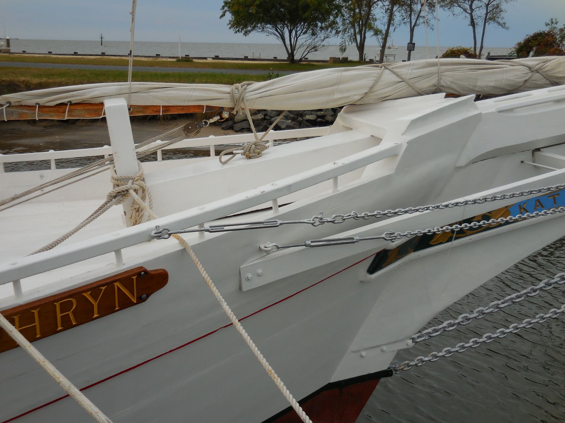
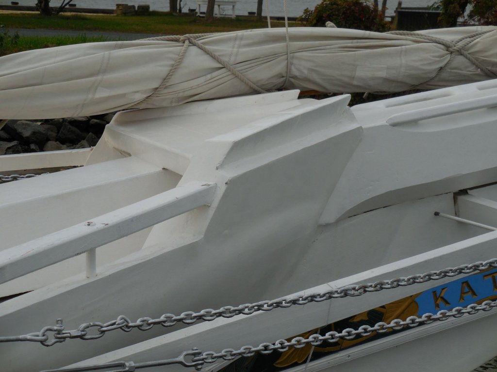
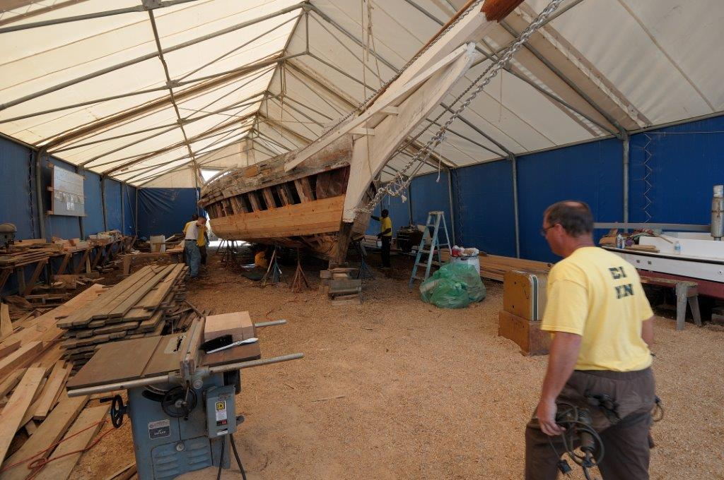
Thanks Druxey. Here are a couple of photos I took of that area. The top of the sheer strake is at the same height as the top of the cutwater, so it looks like the thicker sheer strake is feathered in to the outer stem. I think the area above that is actually the log rail and then a covering for the top of the knighthood. In the photo it looks like a slight bulge that The width of the aft edge of the outer stem is the same as the hull planking, then tapers forward to the width of the cutwater. And here's a photo that shows the same area during the rebuild.

- 878 replies
-
- 15
-

-
Thanks Rich. I guess the only good thing about the heat is that it makes a great excuse to stay in the shop all day.
-
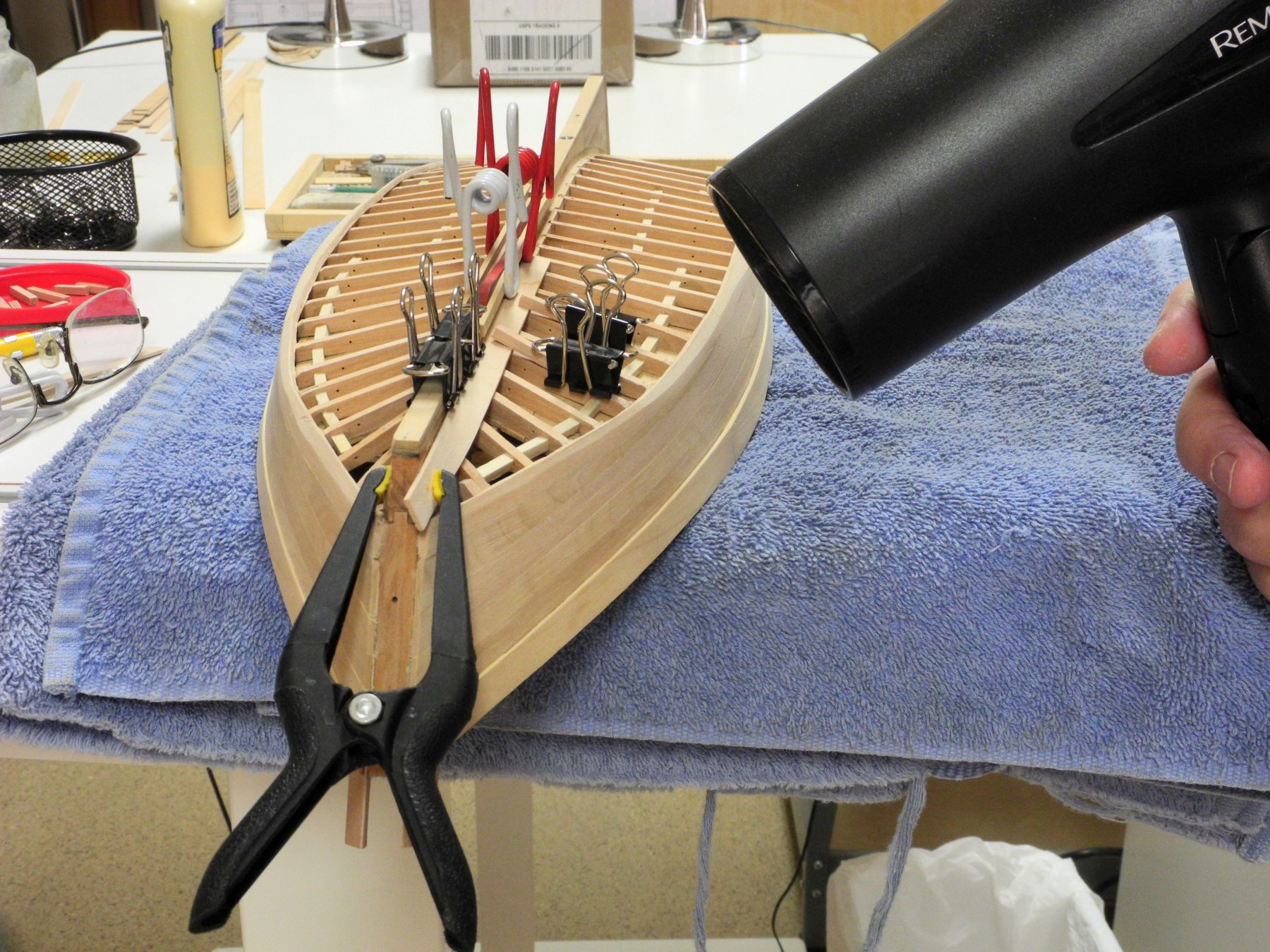
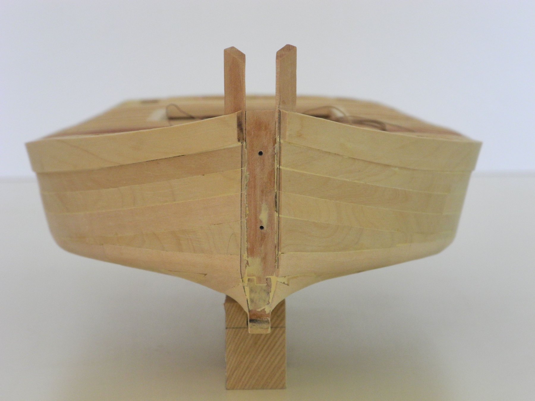
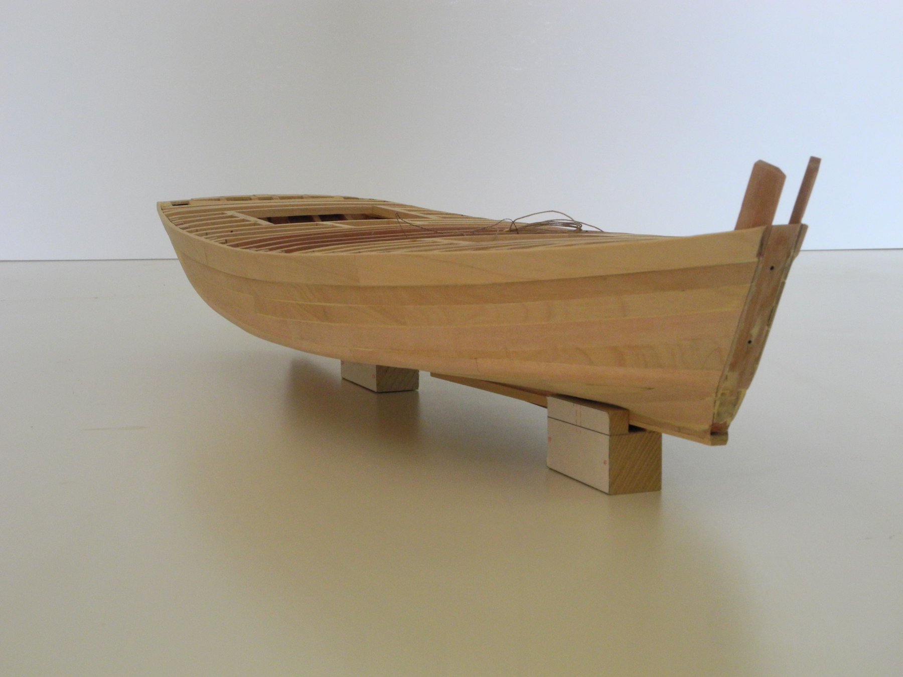
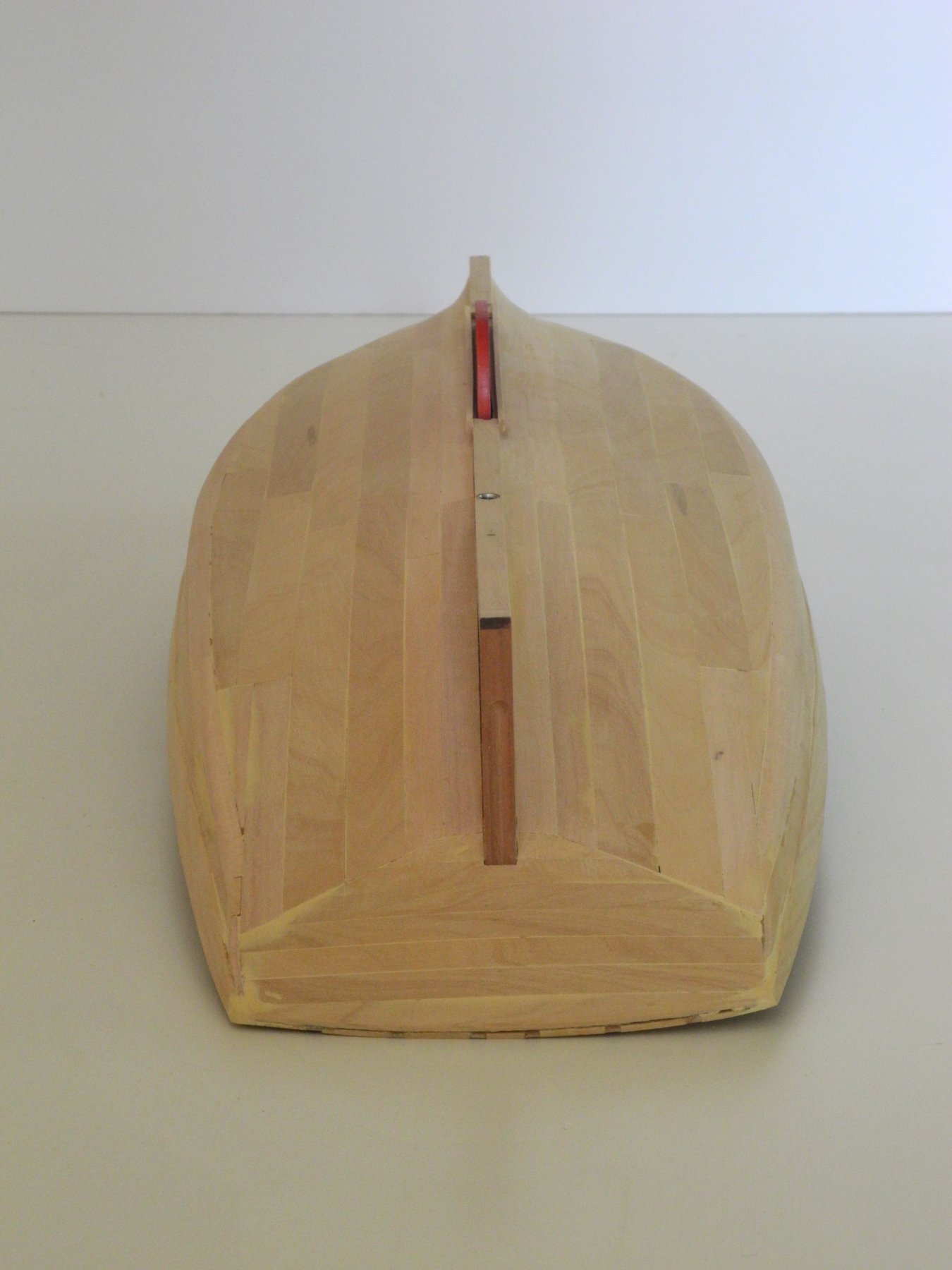
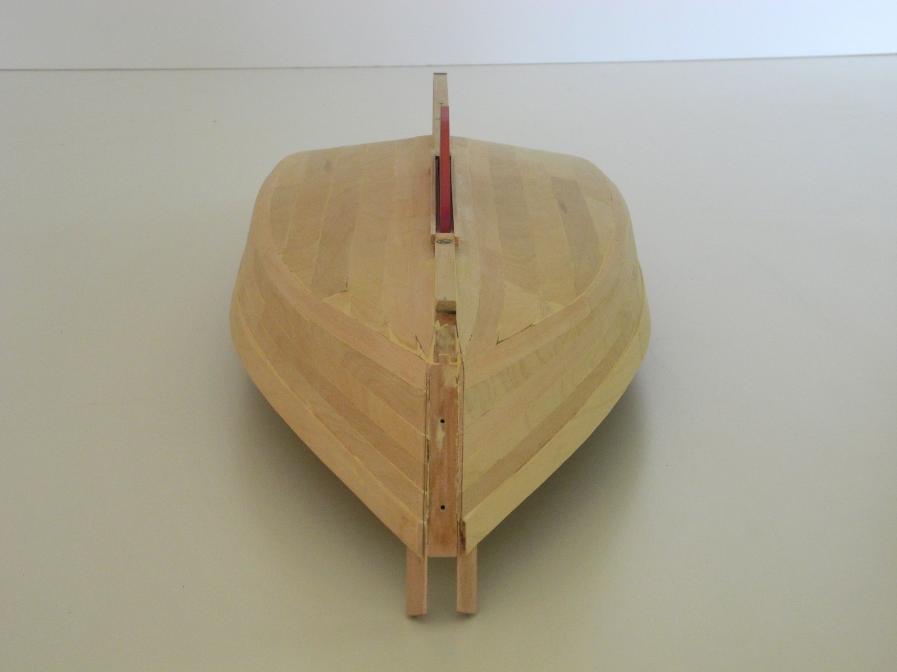
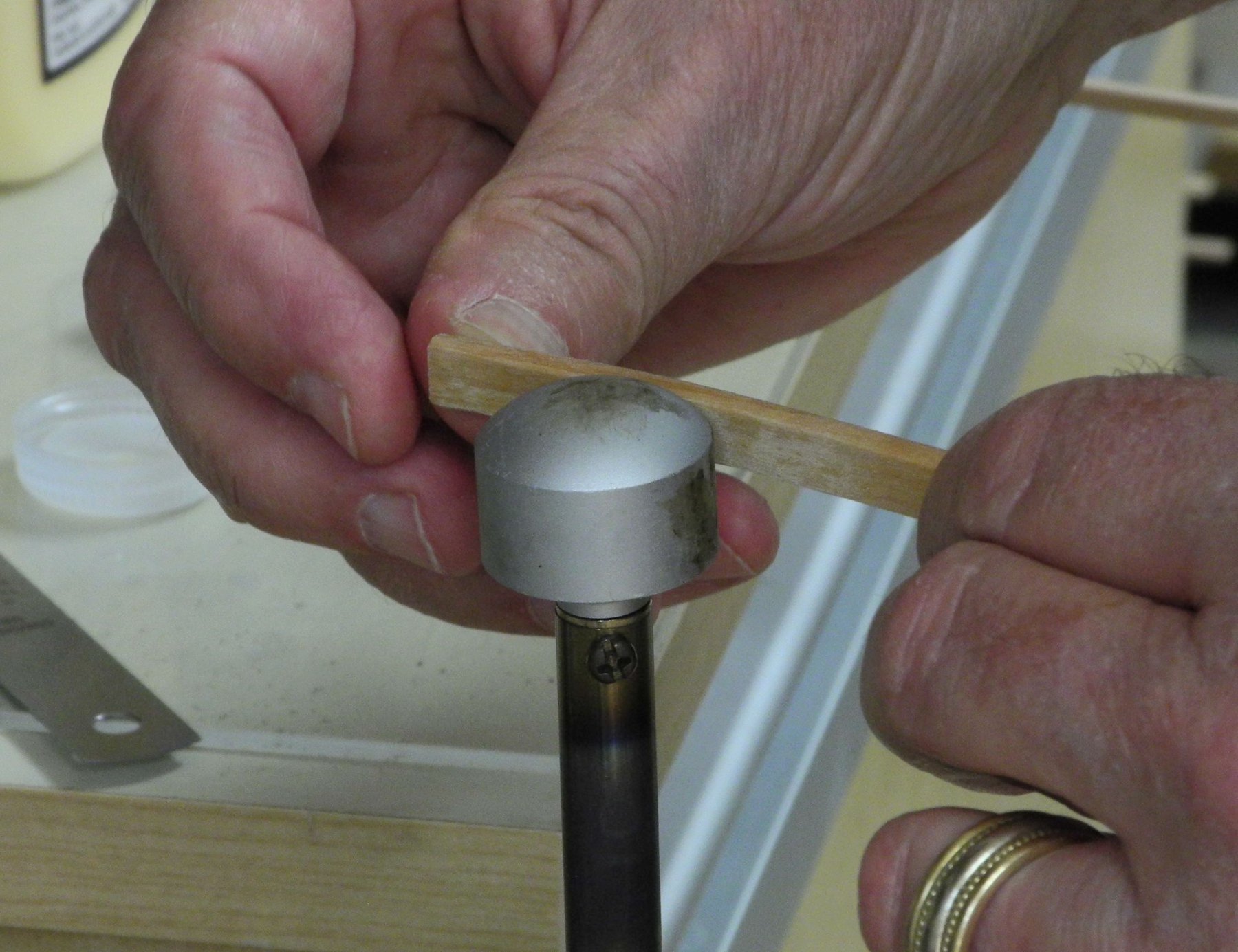
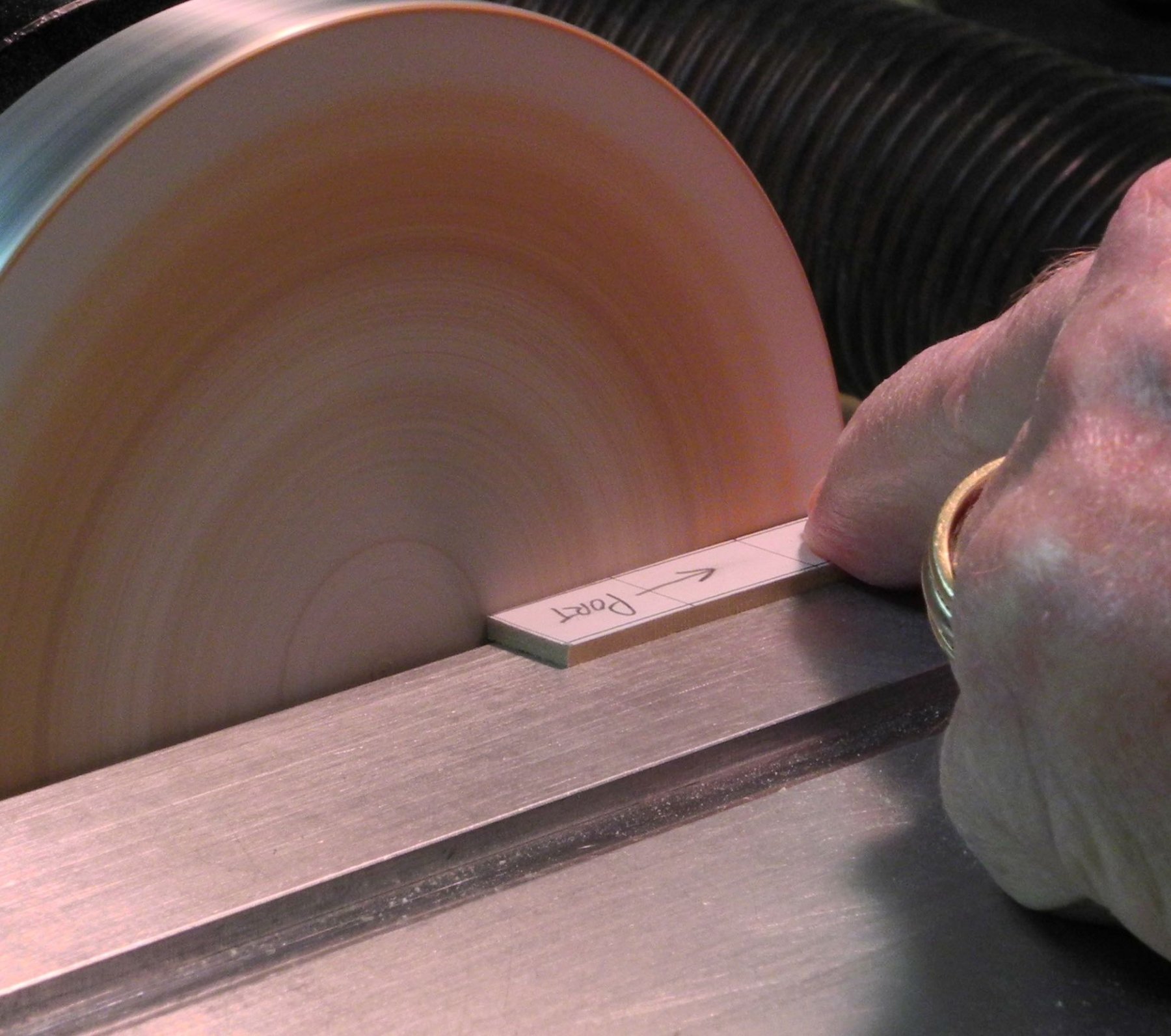
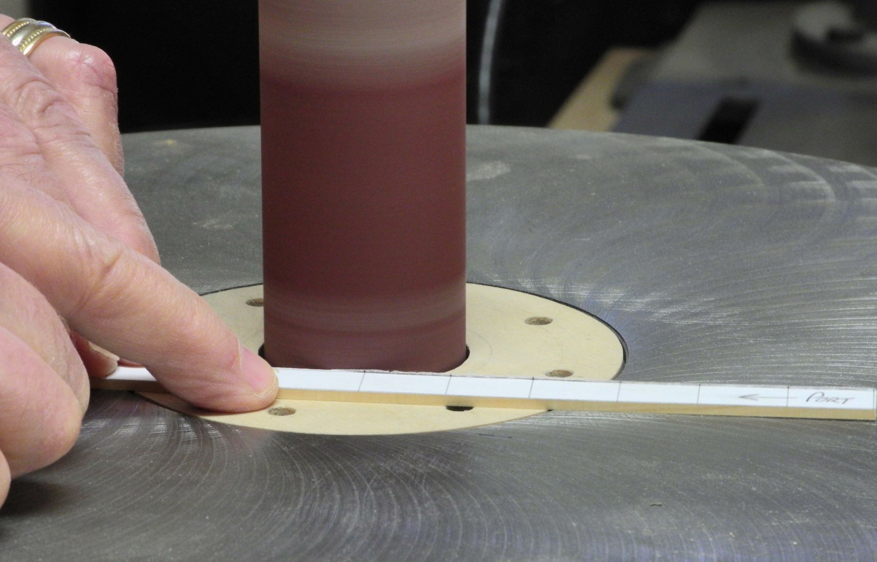
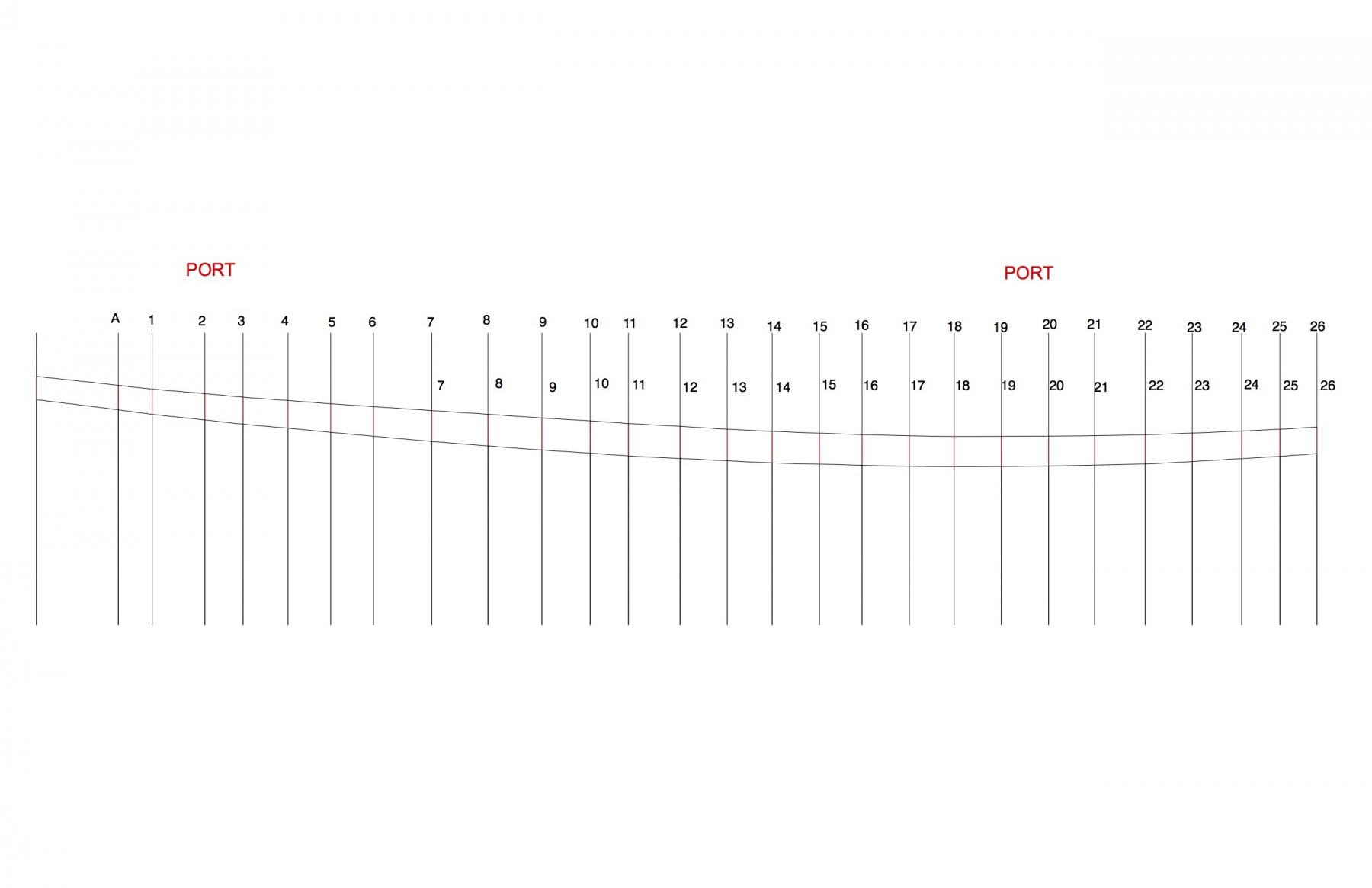
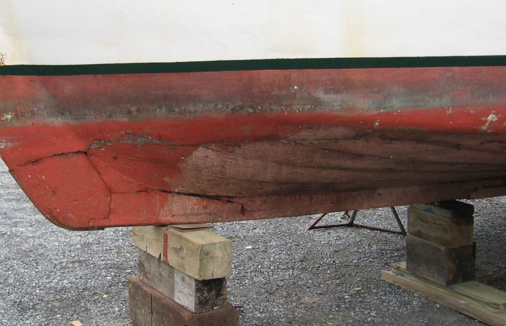
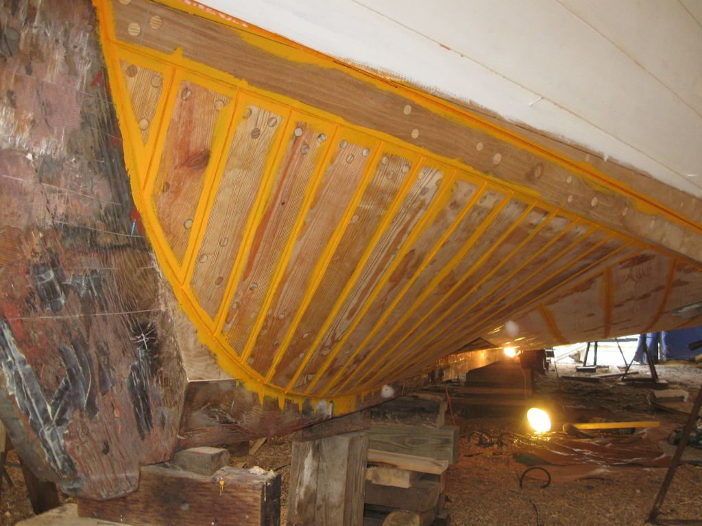
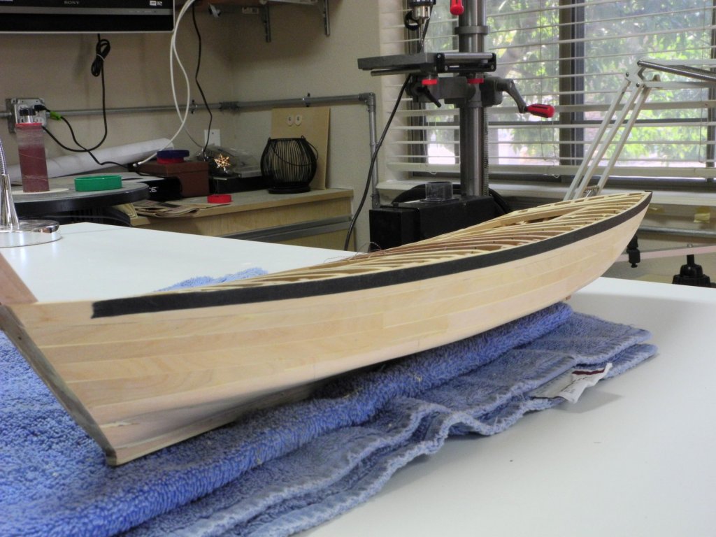
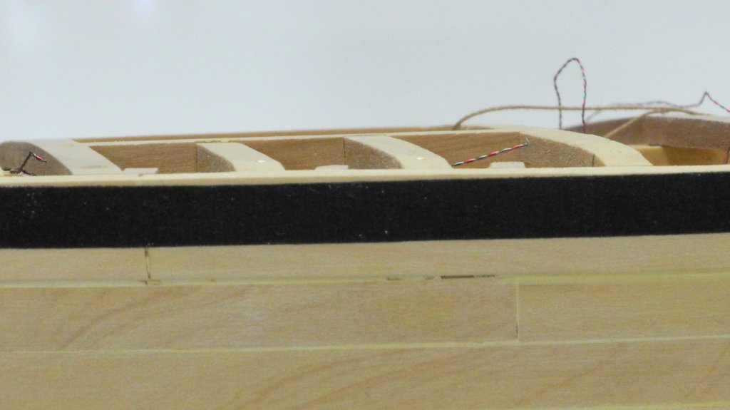
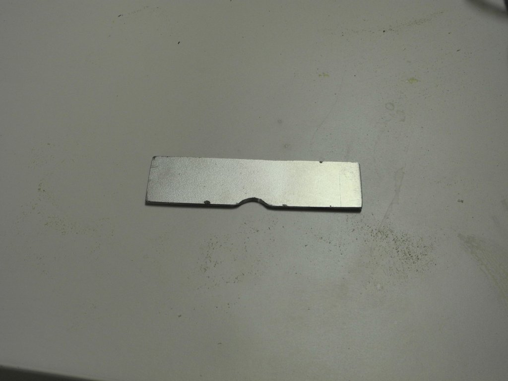
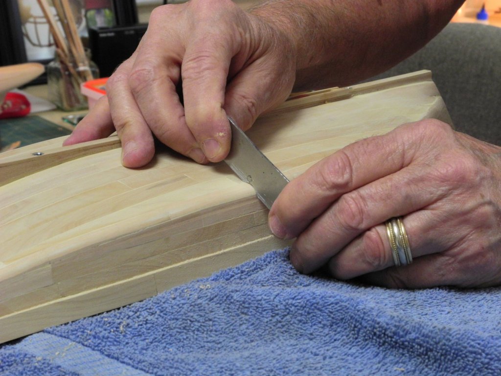
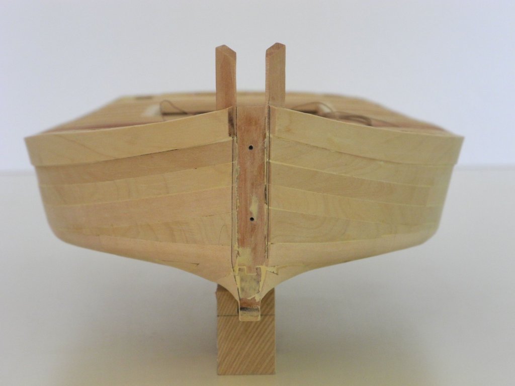
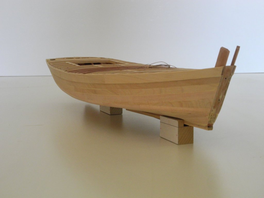
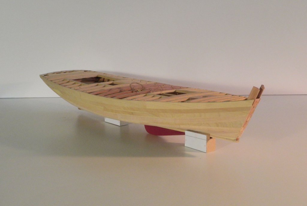
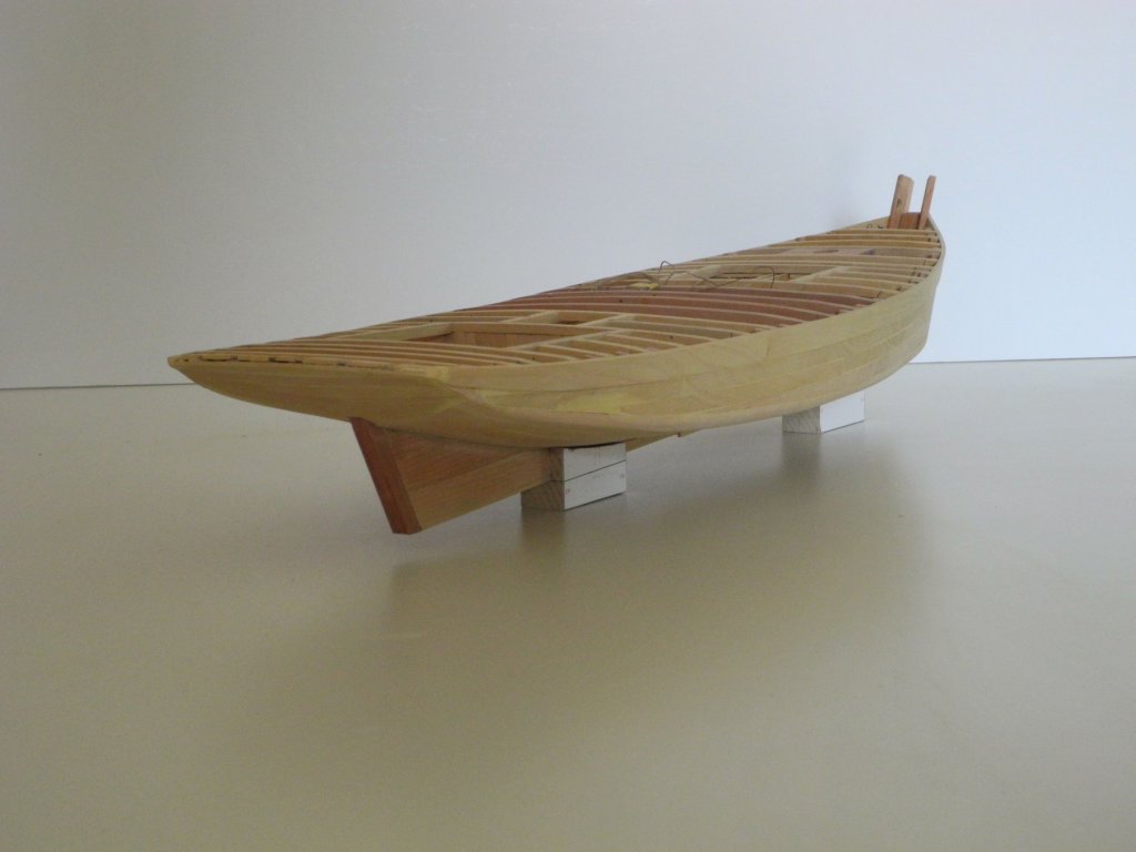
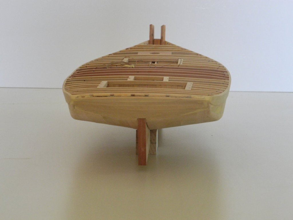
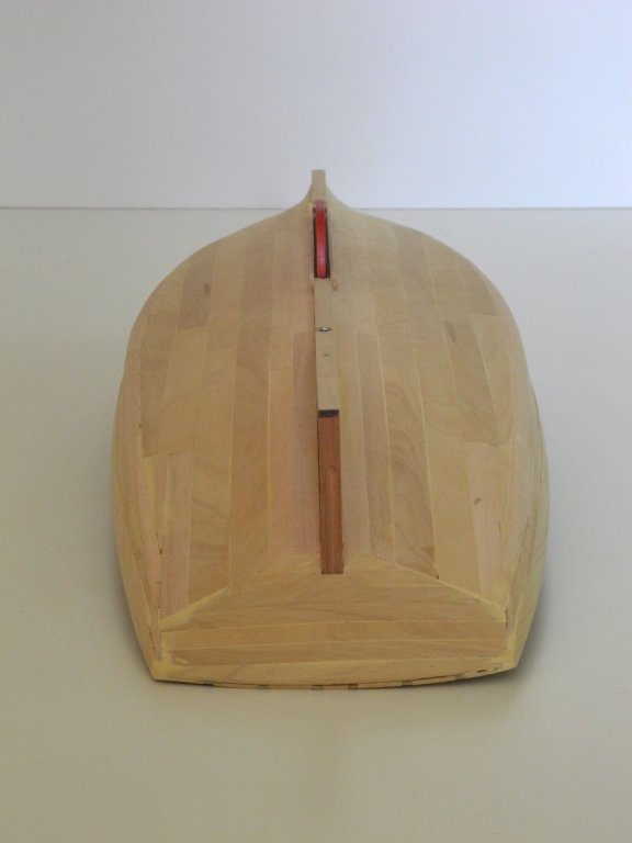
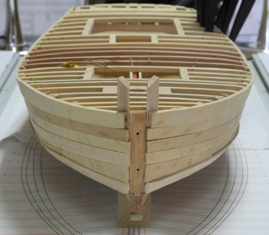
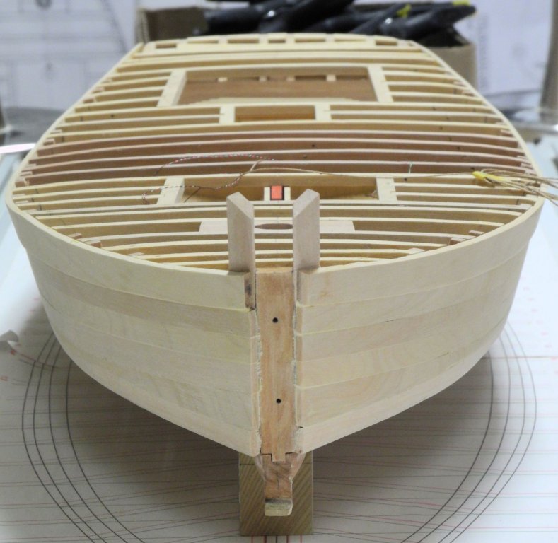
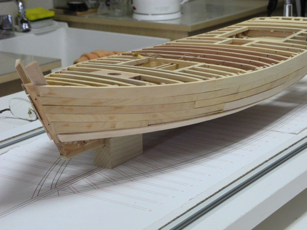
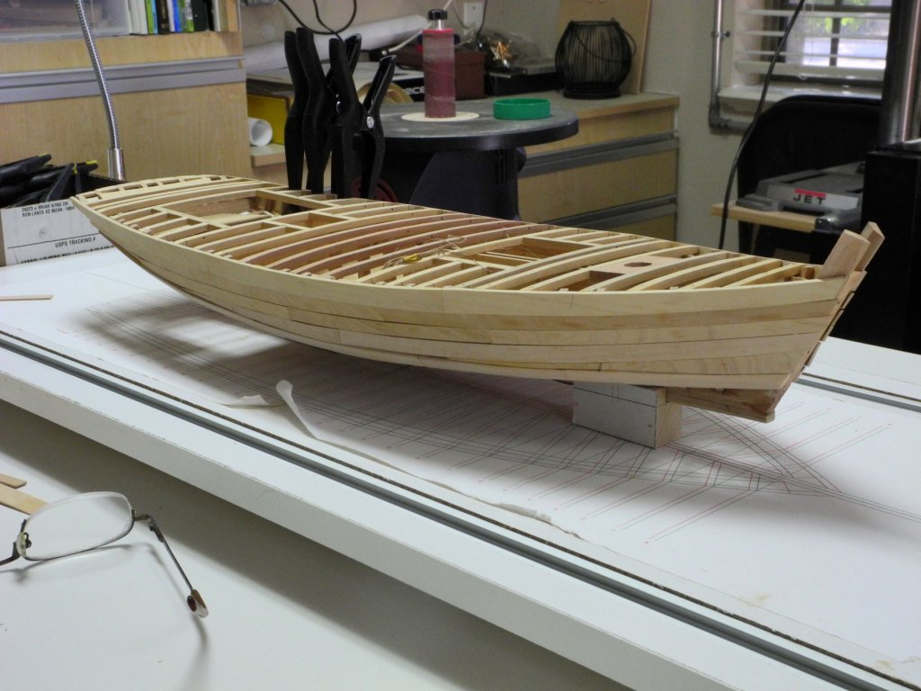
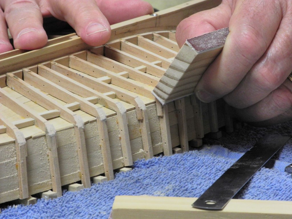
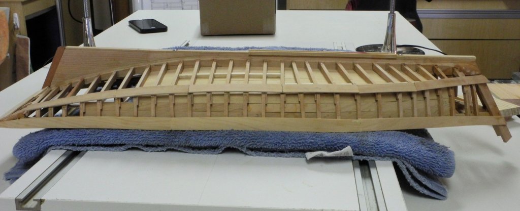
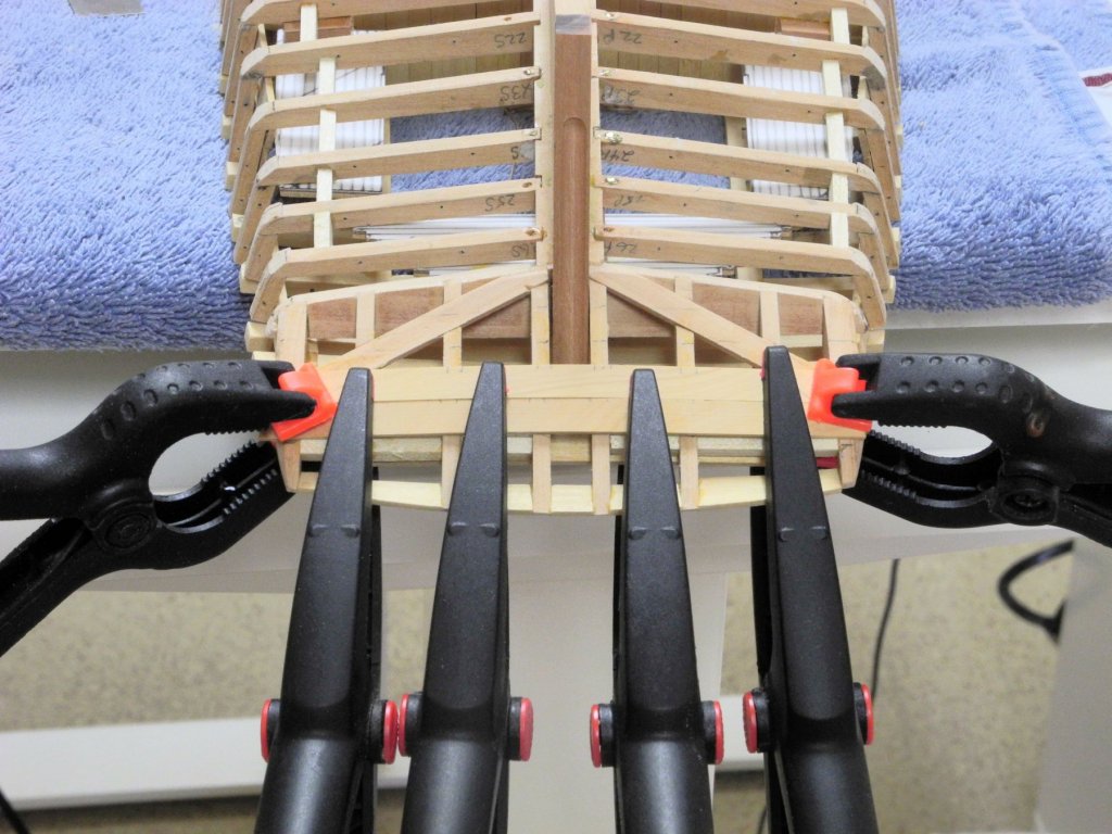
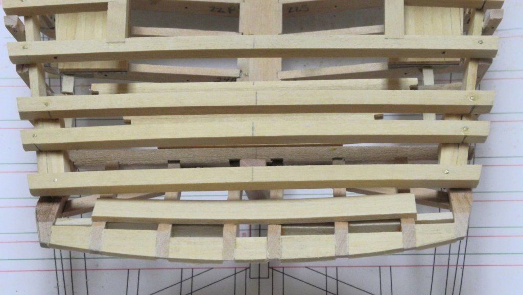
Part 26 – Hull Planking – Bottom Planks There was a comment by Russ in the post on side planking, indicating that there seemed to be a problem in the starboard sheer strake, where the top of the strake had a bulge in it. This was a correct observation, and thanks to Russ for pointing it out. I think that this type of feedback is one of the real values in starting a build log. Other modelers can sometimes see things that we can’t, possibly because we’re too close to our model. I know many people are hesitant to point out issues lest they seem critical, but I welcome this kind of comment – it helps me become a better modeler. I could also see the bulge in the starboard sheer, but I wanted to make sure the correction didn’t cause an issue in the opposite direction. I also wanted to find any other issues in the run of the sheer. So I ran chart tape along the sheer, trying to make sure it ran fair regardless of what the sheer actually did. The tape did point out the problem that had already been discussed, but it also showed a couple of other areas with the same type of issue. The following photo shows a similar issue on the port side. These issues were corrected by careful sanding, using a hard sanding block. The most difficult part of the bottom planking was bending the garboard strake over a fairly short distance. The HAER documentation indicates that with the fore-and-aft bottom planking there is no need for staving or a chunk forefoot, and the garboard plank is twisted at the forward end to meet the stem. This can be seen in the photo on page 238 of ‘Chesapeake Bay Sailing Craft’ by Robert H. Burgess. It can also be seen in the following photo of Kathryn taken prior to the recent rebuild. However, the forefoot was changed during the rebuild, since staving was used instead of twisting the plank. Since the model is following the construction shown in the HAER plans, the garboard strake needed to be twisted to the required shape. After soaking the plank in boiling water it was clamped in place. A hair dryer was used to accelerate the drying time, and the plank was left clamped until it cooled completely. When the bottom planking was completed the chine needed to be rounded to its final shape. A scraper for this purpose was made from a piece of steel. Using this scraper made shaping the chine fairly straightforward. Kathryn still needs more sanding and scraping, followed by priming, before painting can begin. The outer stem and cutwater also need to be installed and shaped to match the lay of the planking. The following photos show the current state of the model. Hmm - after loading the prior photo I see what looks like an issue with the port side of the sheer strake - it seems to flatten a little. I'll need to check the model and see if this needs correction. We leave tomorrow for a fairly long road trip (hopefully to cooler temperatures!) so Kathryn will be put aside for a while. Thanks everyone!


- 878 replies
-
- 24
-
-
Thanks Druxey. Russ is correct, and the fix will be fairly easy. I'll be spending some time looking for other areas to correct before painting. Thanks Rich. Welcome back. This week will be a good test of the new A/C for your shipyard.
-
Thanks Patrick. Kathryn is considered one of the faster skipjacks in the Chesapeake Bay. One of the the things that made me want to build the model is her beautiful lines - I hope I do her justice.
-
Amazed as always with your creativity, Patrick. Shadow is looking great. I forget how small she is until you show her next to fruit, or your watch, etc.
-
Thanks Russ - I see what you're referring to and I'll check it to morrow. I haven't finished all of the fairing work, and there is still some future construction above that sheer strake (planksheer, railings, etc) so I think it will work itself out.
-
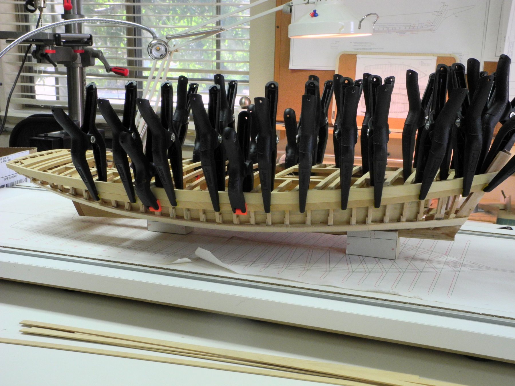
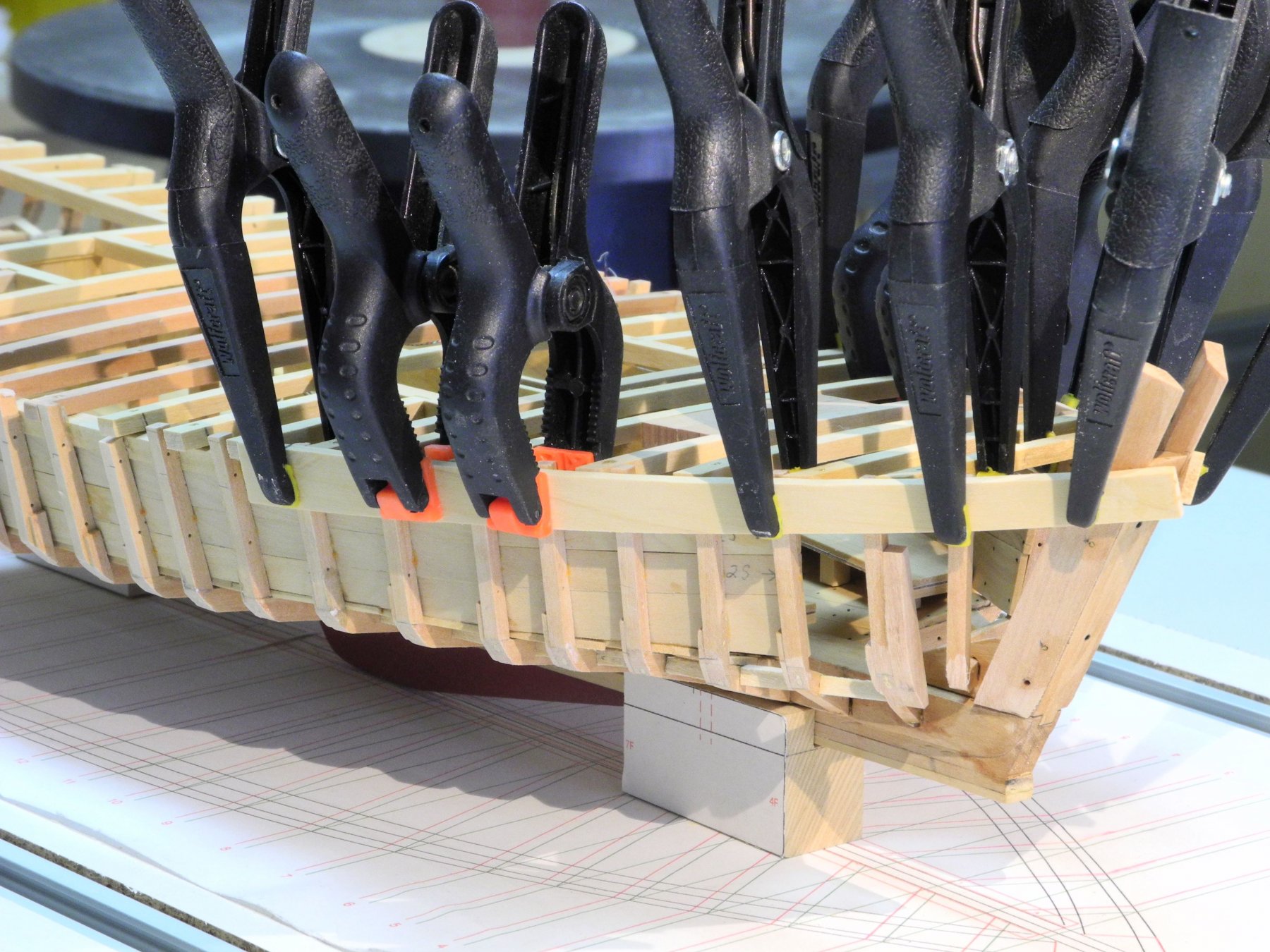
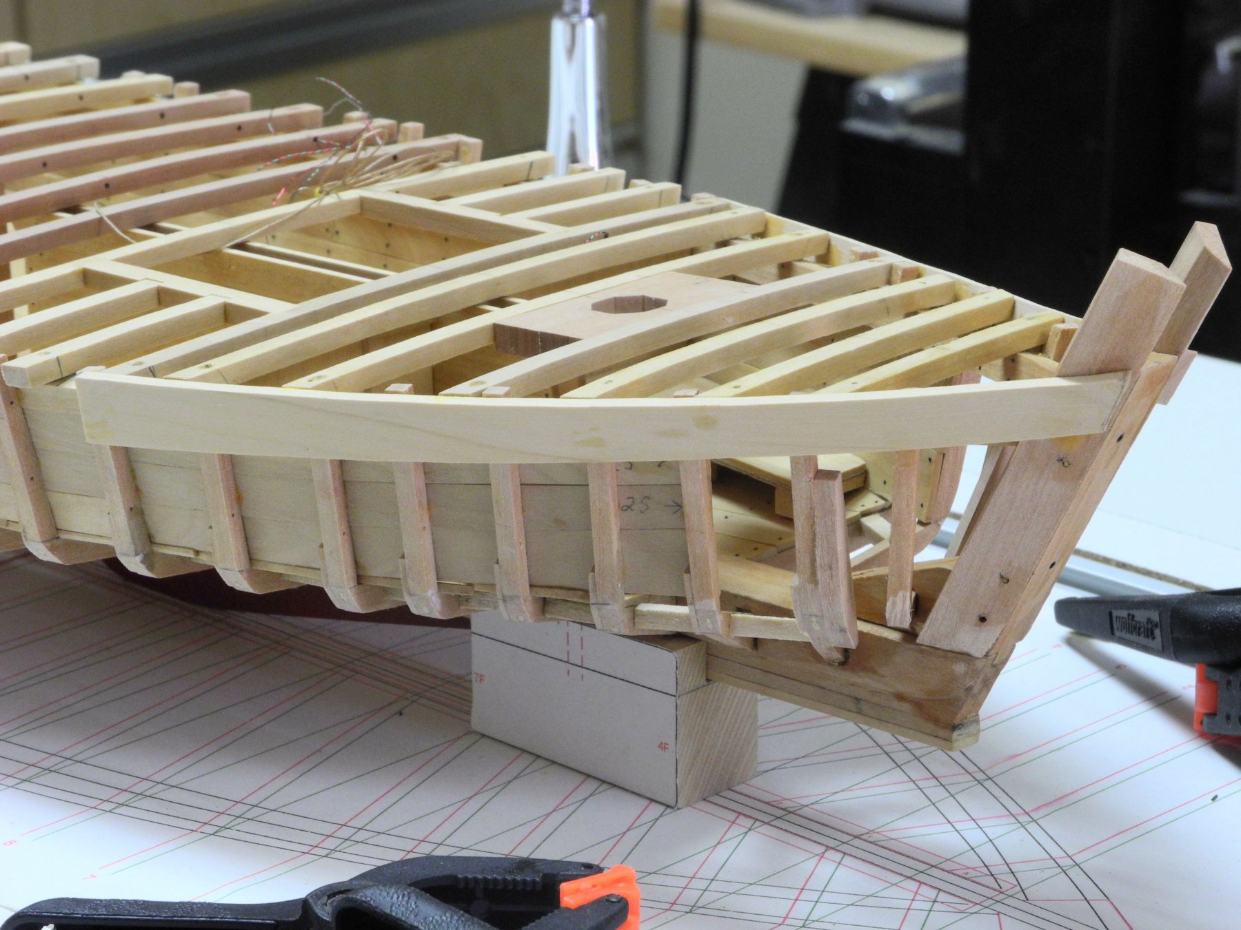
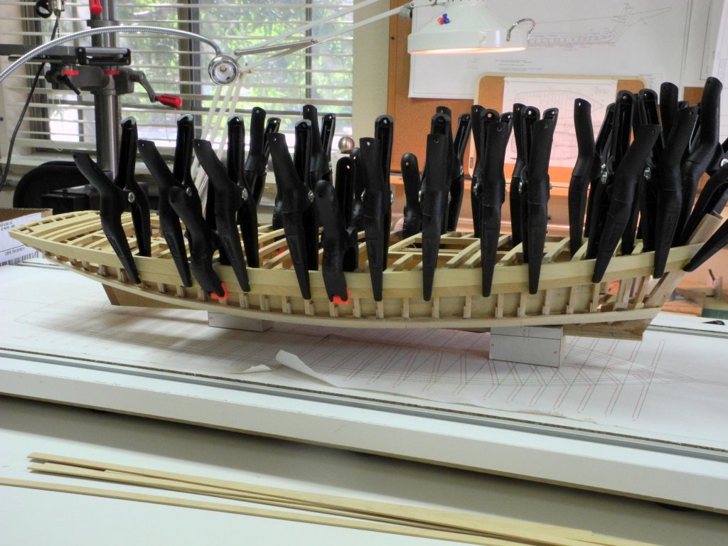
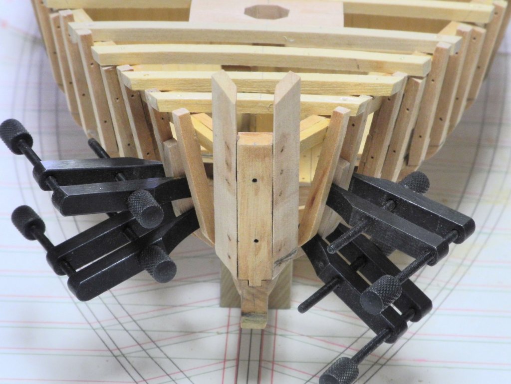
Part 25 – Hull Planking – Side Planks After a full day in the shop the hull planks have been installed on Kathryn’s sides. This went very quickly, but I have to admit that the reason for the speed is that I didn’t spend any time laying out the planking, spiling, or generally taking a lot of care in how the planks look. Since Kathryn will be painted I decided to simply get the planks in place and then to finish the sides by scraping, sanding and a liberal use of wood filler. Normally I would focus on one plank at a time, but in this case I was able to install a strake on each side without much trouble. Most of the clamps in the photo are micro needle-nose clamps I was able to find at Menards. Their length allowed me to clamp all the way down to the bottom strake. They’re priced very reasonably, even with shipping and handling. Here’s the link for the clamps. https://www.menards.com/main/tools-hardware/hand-tools/clamps-vises/wolfcraft-reg-micro-needle-nose-clamp/p-1444439537678-c-9135.htm?tid=5859562028242466227&ipos=1 When the planking was completed, but before sanding and filling in the spaces Kathryn looked pretty rough. But after the initial cleanup she’s starting to look pretty good. Here are some ‘before’ and ‘after’ photos> There’s still a lot of cleanup needed before painting. I’ll be installing the bottom planks next, and then will spend some time rounding the chine and getting the hull ready for painting. Thanks Everyone!


- 878 replies
-
- 25
-
-
Hi Russ. My understanding is that the hard chine boats are built the same way on the Chesapeake. Kathryn was likely built in a more traditional manner - upright.
-
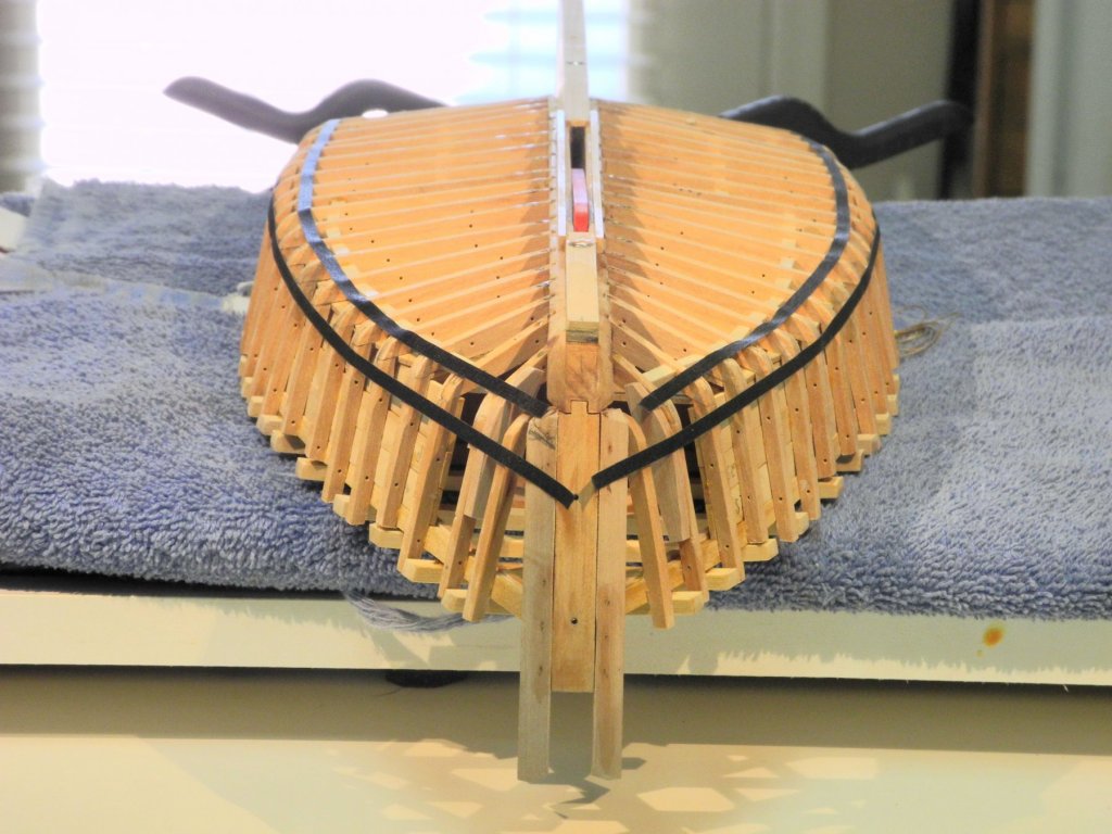
Hi Russ: Thanks! Most skipjacks have a hard chine, bottom planks laid in a herringbone pattern, and are built without true frames. Kathryn and a small number of others was built with traditional frames, longitudinal bottom planks, and a rounded chine. The construction process between the two styles is very different.
-
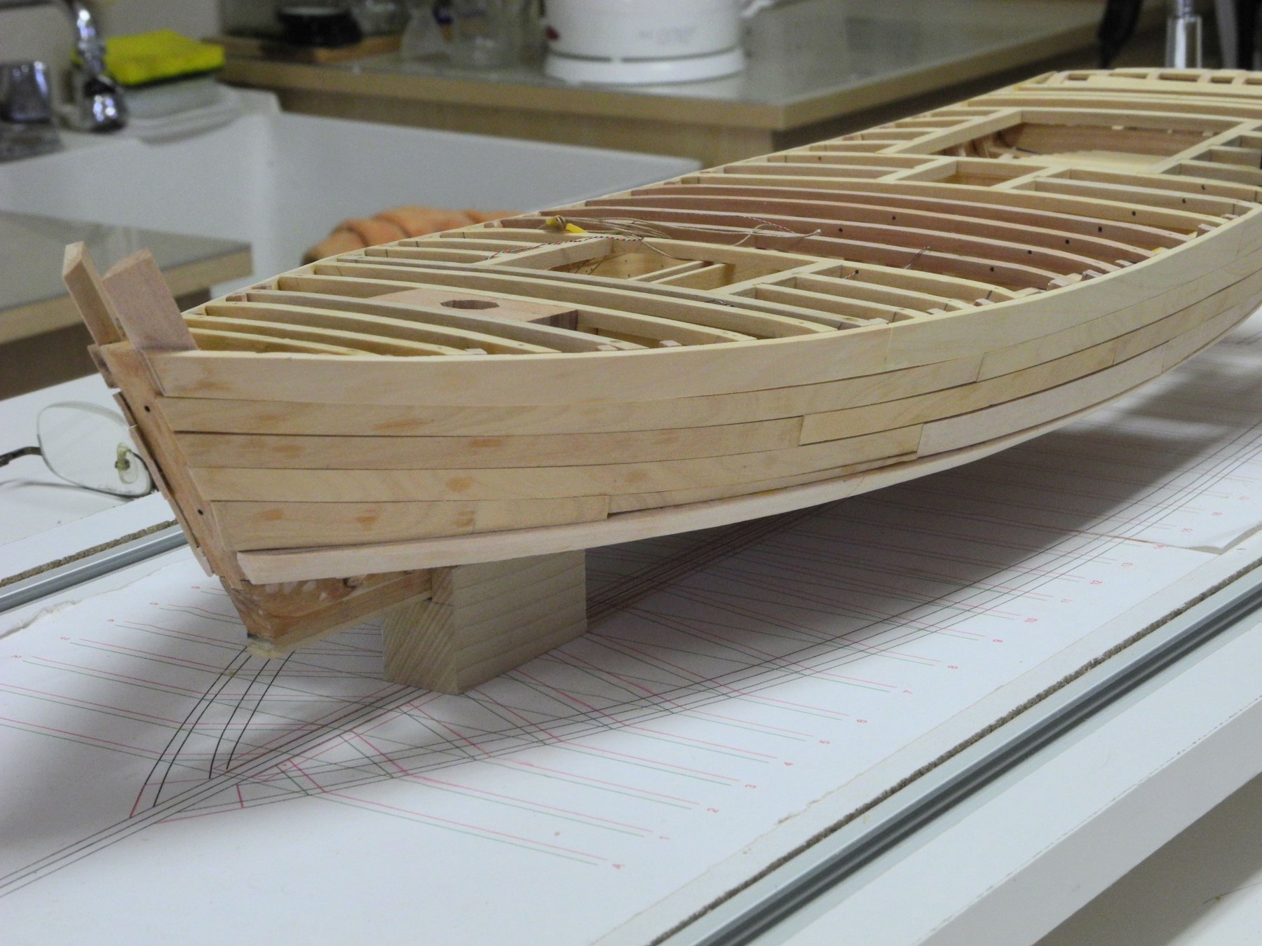
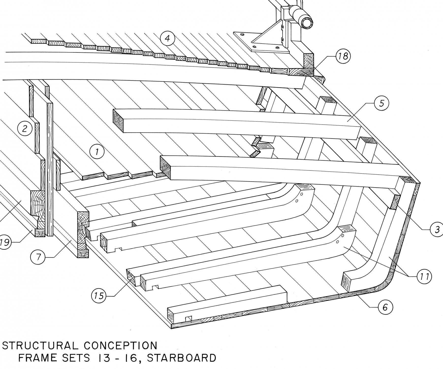
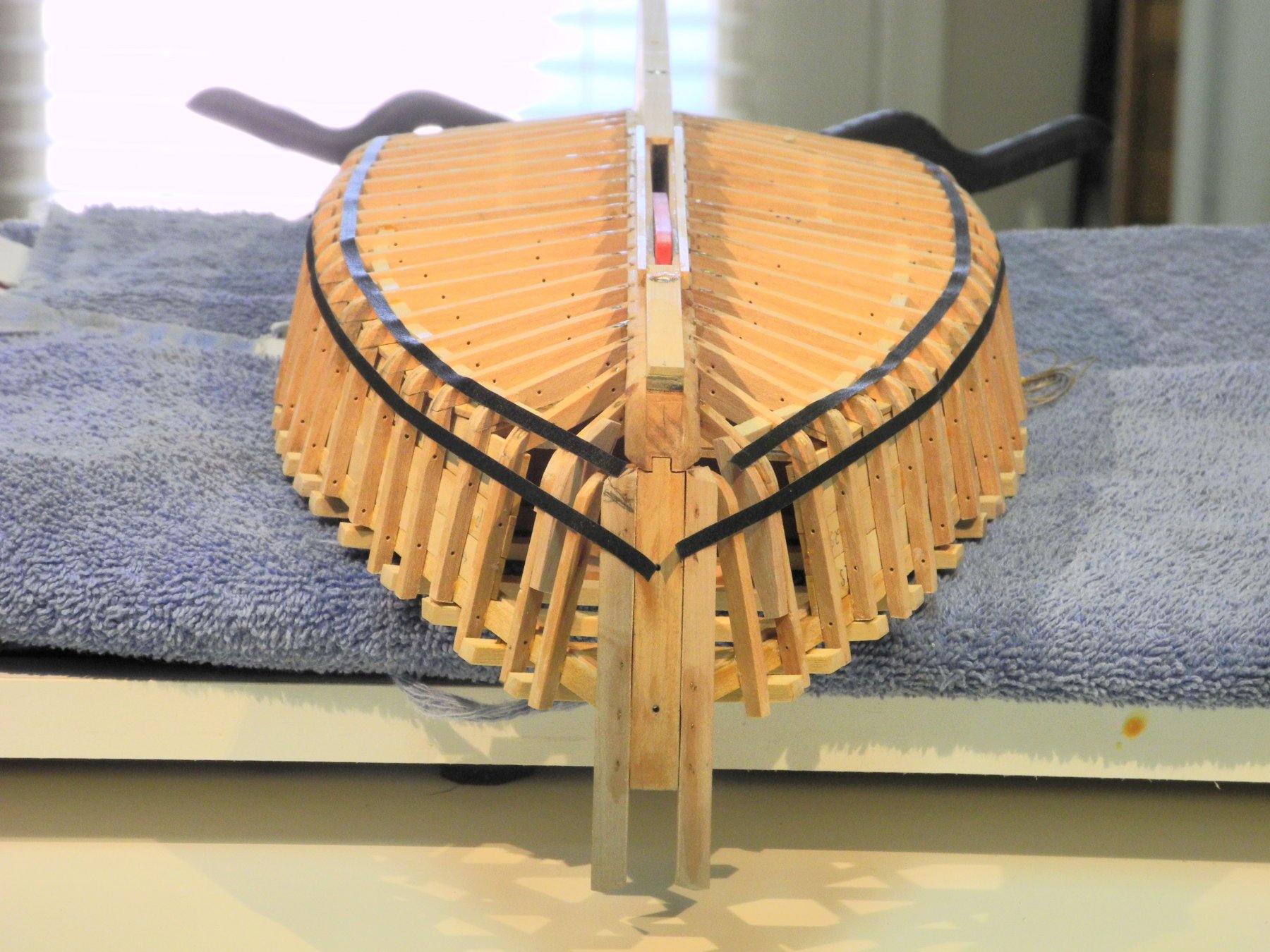
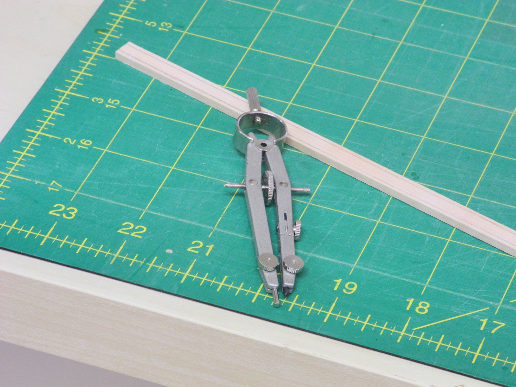
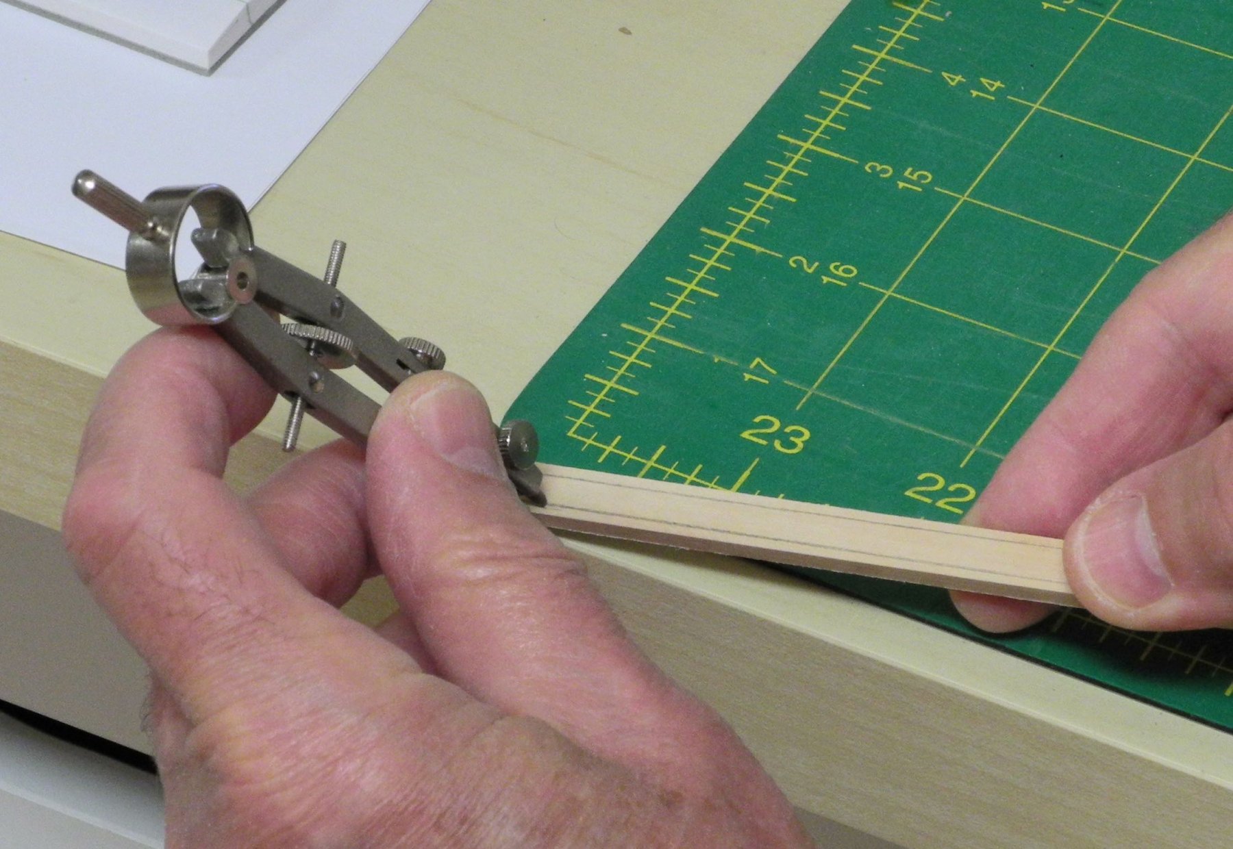
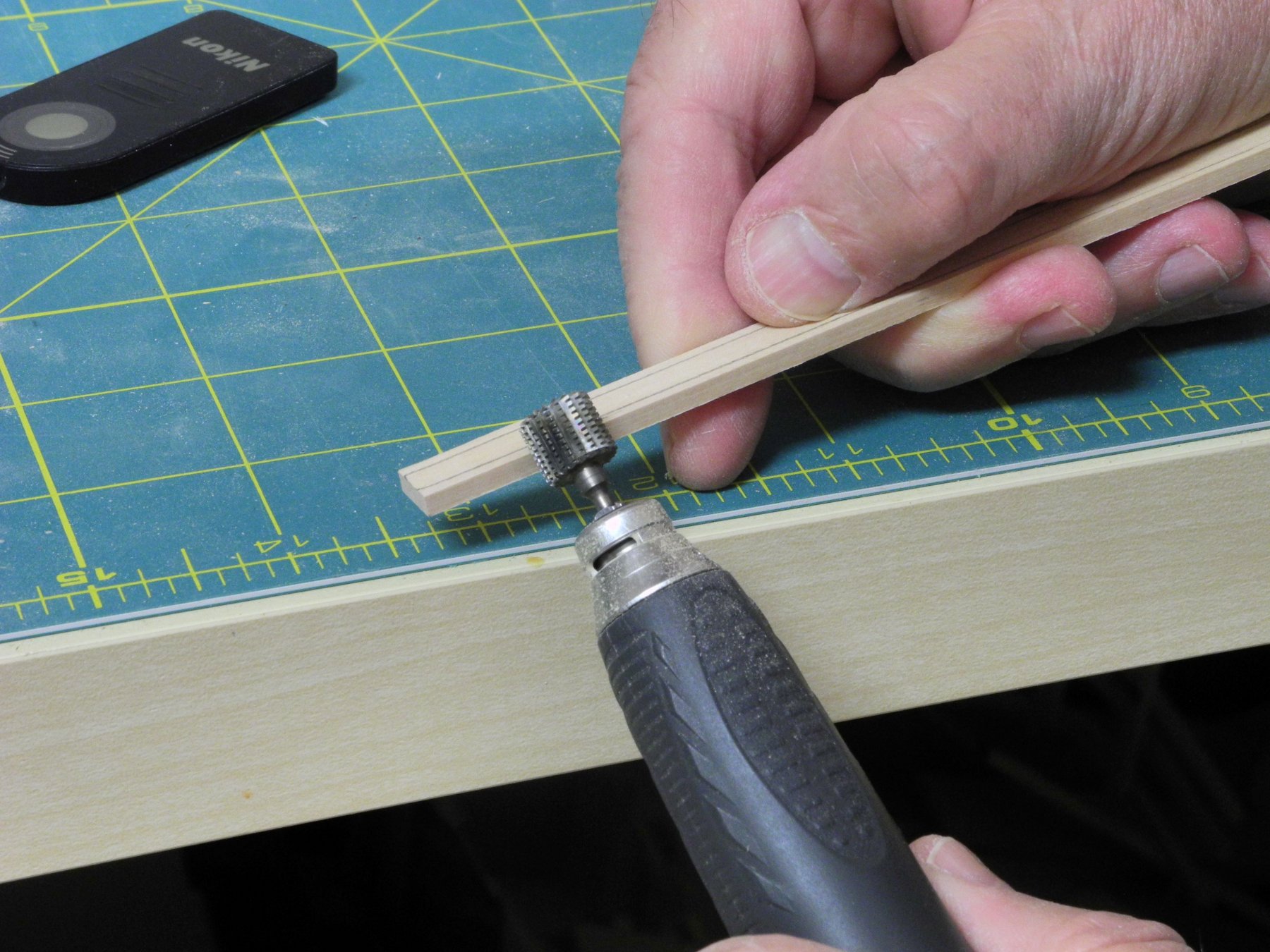
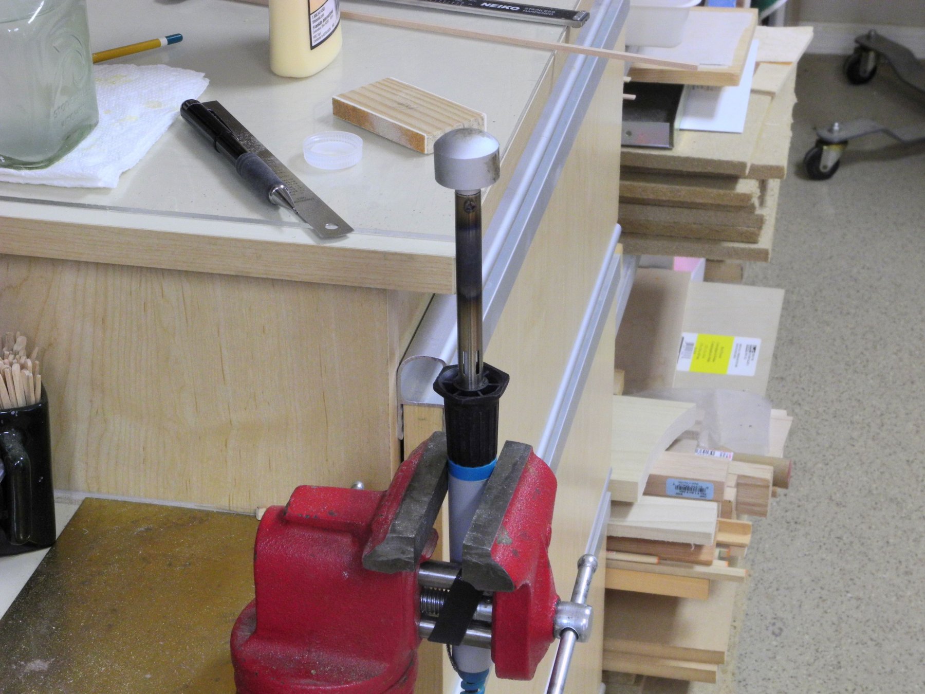
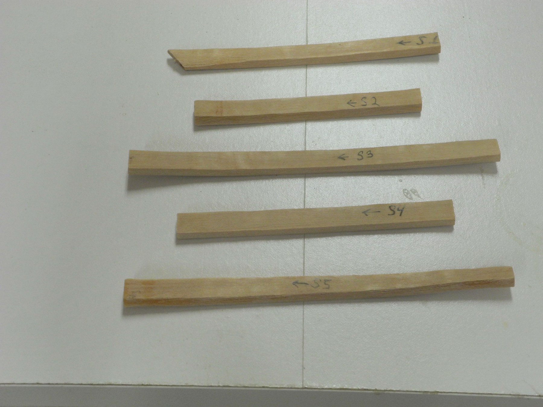
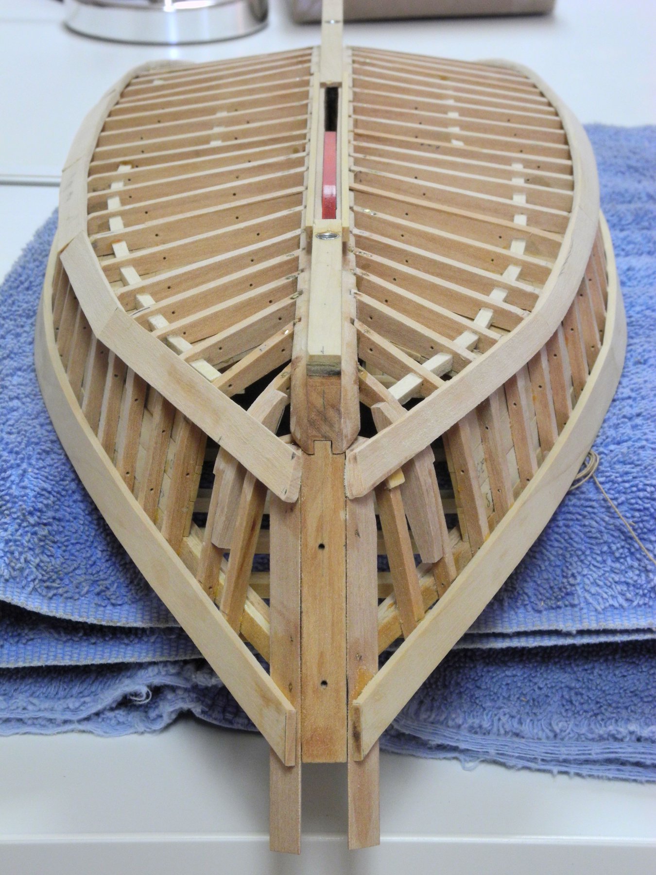
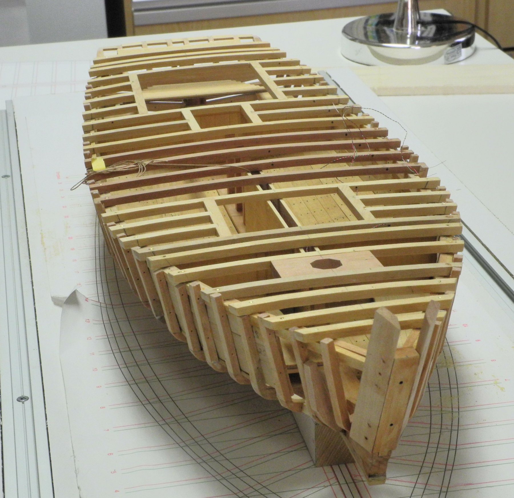
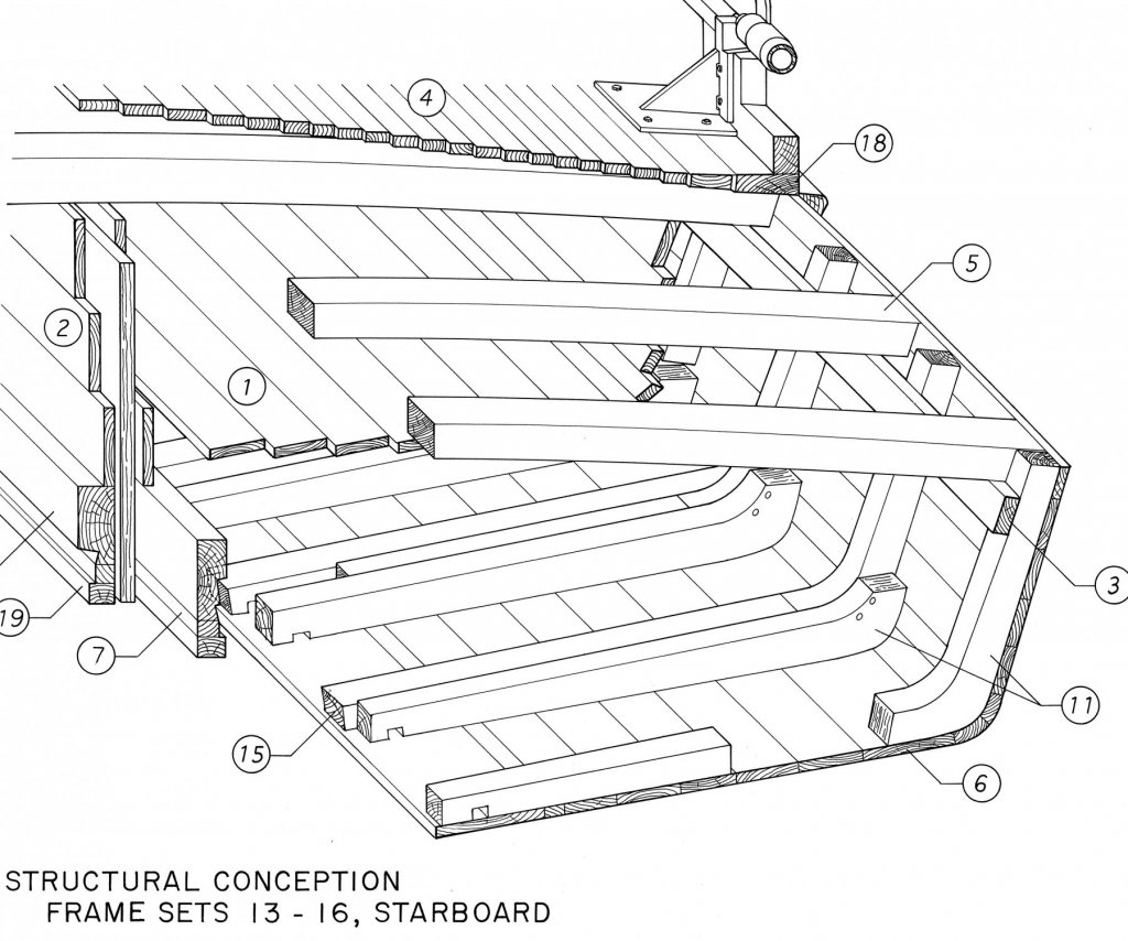
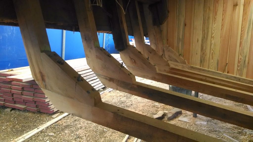
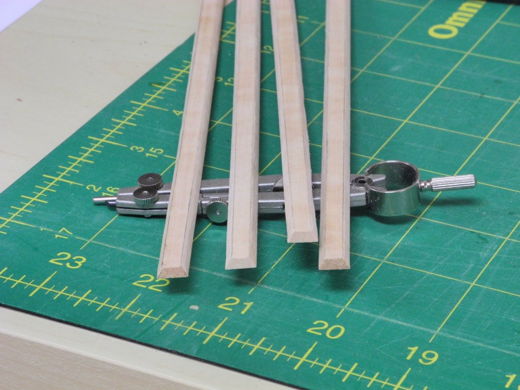
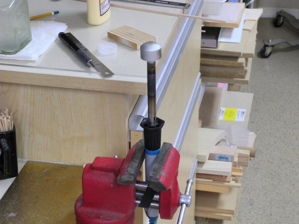
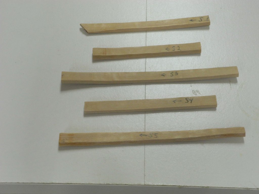
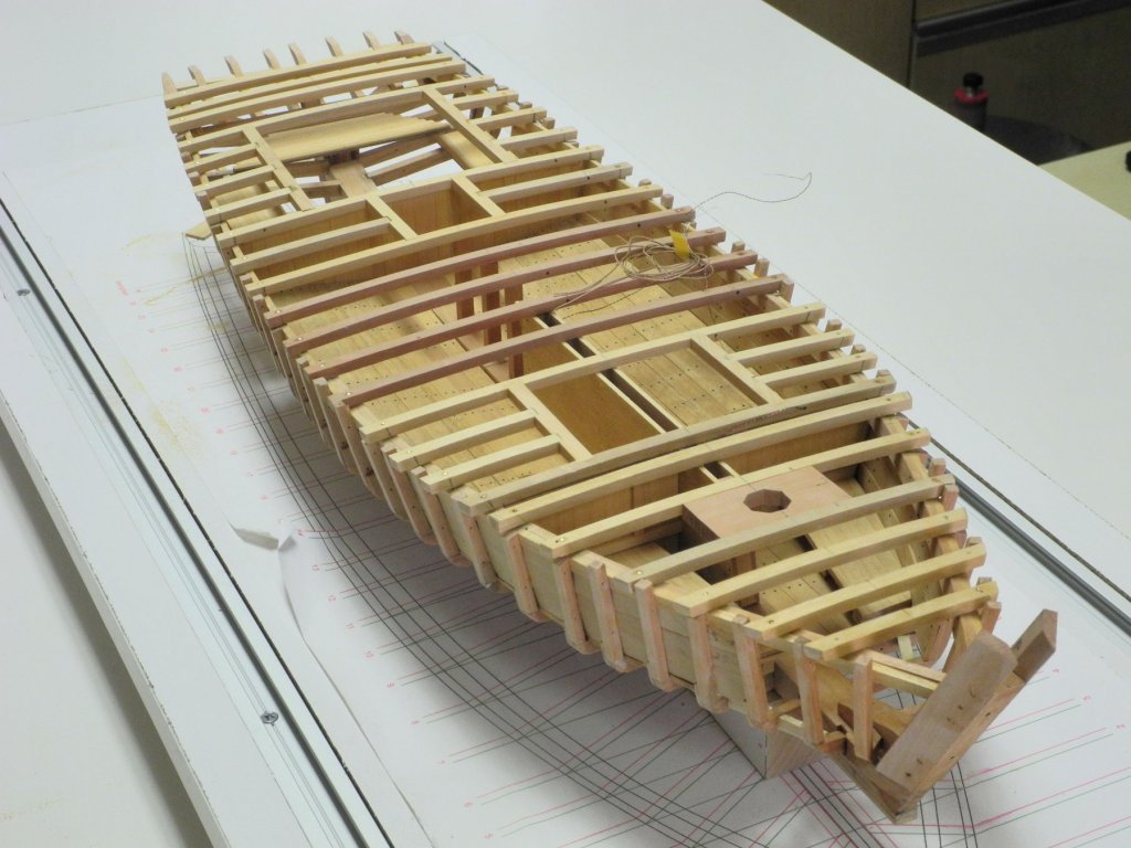
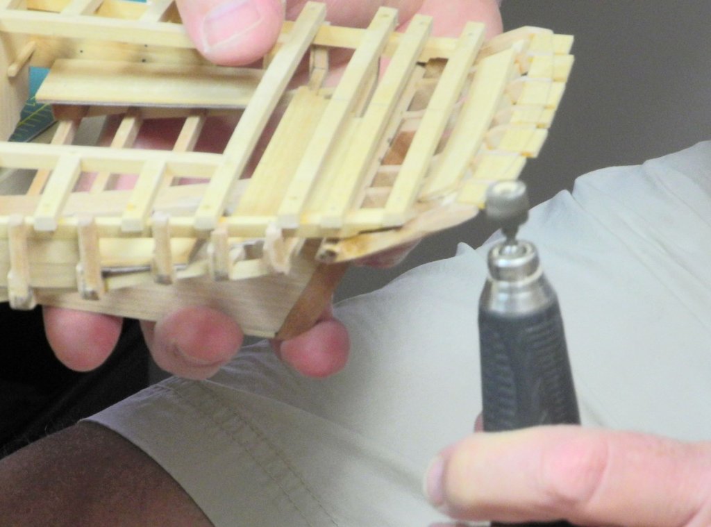
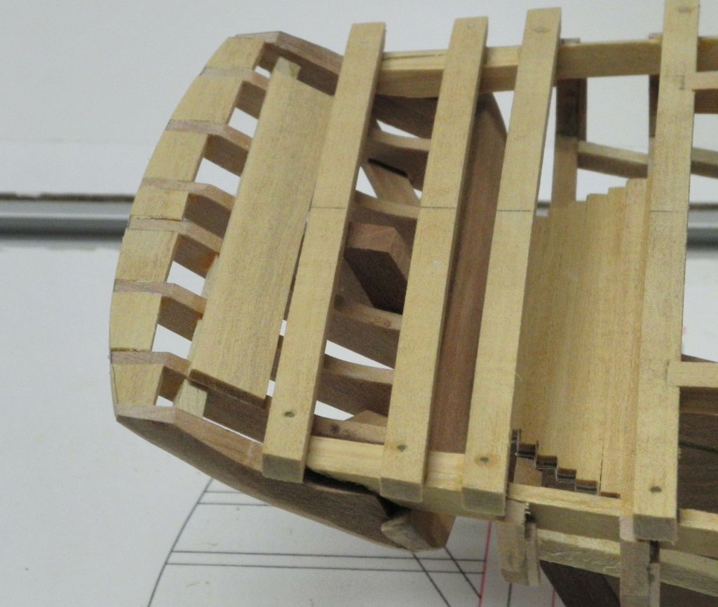
Part 24 – Hull Planking – Preparing the Chine I was able to develop a workable approach to installing the chine. First, some background: All of the cross-sectional drawings in the HAER documentation show the rounded chine and also show the frames as rounded at the chine. One drawing, from Page 6, actually depicts the planks used in the chine area and shows them cupped around the frame. I had not been able to determine an approach for making this type of chine plank for the model. I have been in contact with one of the people who worked on the Kathryn rebuild, and he told me that during the rebuild the chine planks were installed as thick planks and then were planed to form the rounded chine. Looking through photos from the rebuild, it can be seen that the chine area of the frames was made flat, rather than rounded, so that flat planks could be used for the chine. The frames that were installed on the model have the rounded chine, so these needed to be modified to allow flat planks to be used. The first step was to line off the chine using drafting tape, and then to mark the upper and lower boundaries of the chine on each frame. Using the marks on the frame, a sanding block was used to flatten the chine. The following photo shows the model with all of the frames flattened in the chine area. The chine in most of the frames is the same width, but this decreases for the last 6 or 7 frames approaching the stern. Thick planks were milled for the chine. Although the documentation indicates that 3 planks were used in the chine, I decided to use a single plank to simplify the construction. The planks were lined out on each side to allow beveling the sides of the plank so that the hull planking could sit flush with the chine. The chine planks are significantly thicker than the hull planking that will sit next to the chine. This will allow the chine planks to be rounded after all of the hull planking is installed. A compass was used for lining out the planks. The metal point was reversed so that the compass would ride along the side of the plank and give a consistent width of the line. The planks were lined out for the bevels on each side. The bevels were then cut into the planks using a stump cutter in the rotary tool, followed by some final sanding. The chine planks would need to be bent to fit properly. I decided to install the planks as short sections that were pre-bent to fit the respective location. Bending was performed by soaking the piece of chine in boiling water, and then using a plank-bending tool to form the shape. The tool was held vertically in a bench vise. All of the pieces required for a side were made before any was installed. The pieces were labeled for sequence and direction. The following photo shows the port side chine after the initial installation of the chine pieces. It can be seen that a lot of subsequent shaping is required before there would be a fair run of these planks. The following photo shows the starboard side after some initial shaping, and the port side awaiting shaping. Both chines have now been installed and shaped for their final configuration Next up is the installation of the hull planking for Kathryn’s sides and bottom. Thanks everyone, and Happy Fathers Day to all the Dads (and Grandfathers) out there!


- 878 replies
-
- 21
-
-
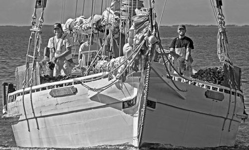
Thanks Ed. Even though they're not ocean-going, it's amazing to think of the kind of beating these old skipjacks take during the winter oyster season. This photo is from a book on working skipjacks and it shows Kathryn in 2016, some few months after the recent rebuild. All of the plank seams show - needing a new paint job already!
- 878 replies
-
- 10
-
-
Hi Brian - sorry to hear you're not well. Get better soon. Unfortunately I meant today and tomorrow. We leave on a road trip on Thursday morning - going places that are a little less warm than here. I'm hoping to have Kathryn's hull planking finished before we leave.
-
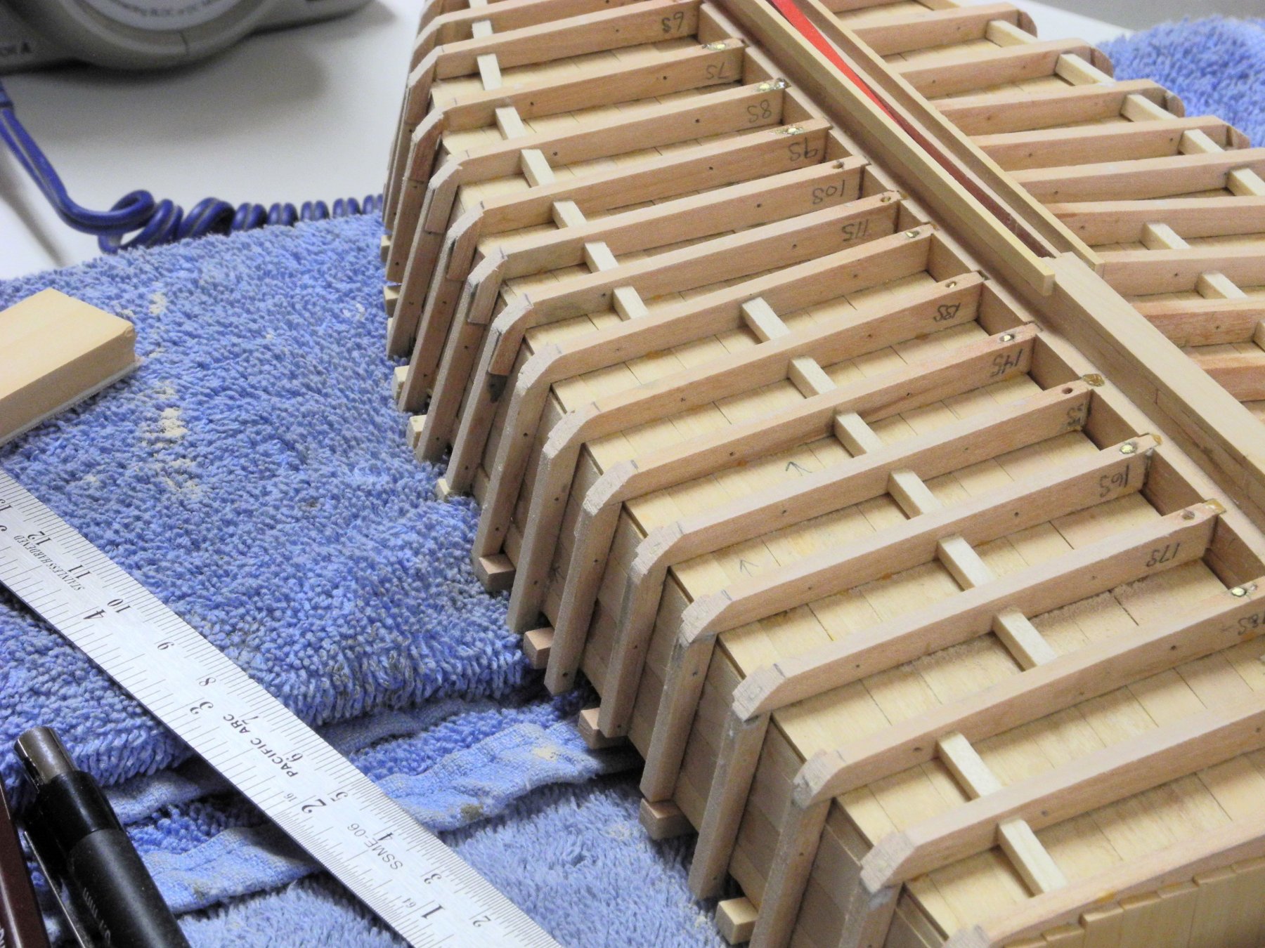
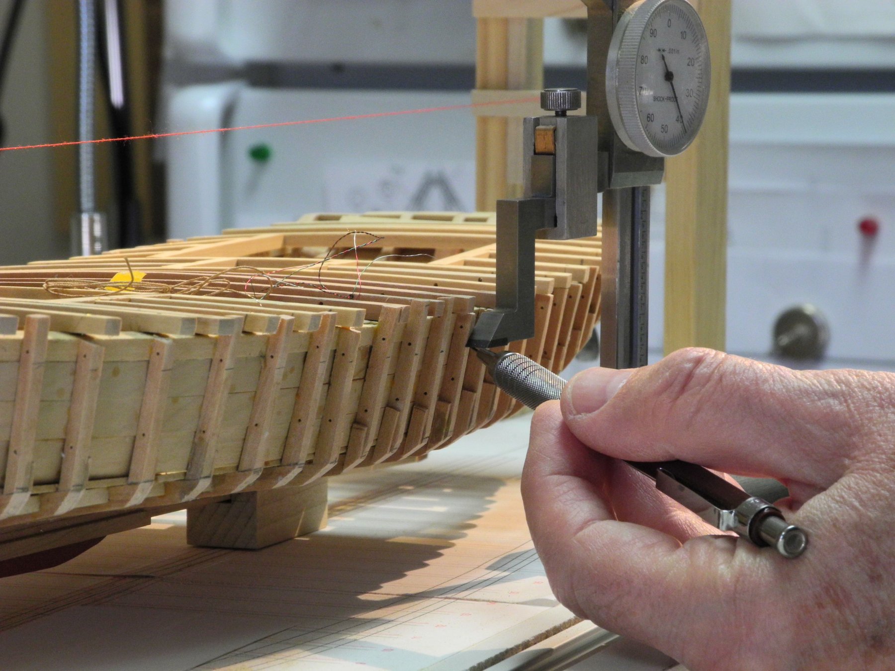
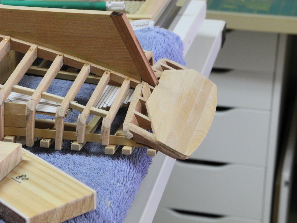
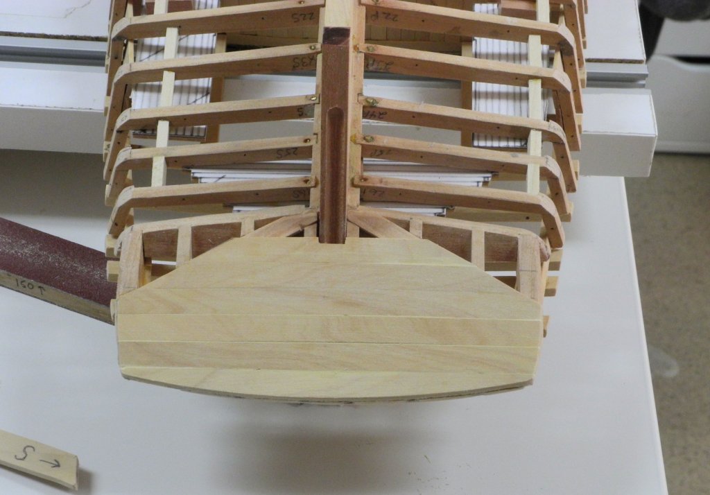
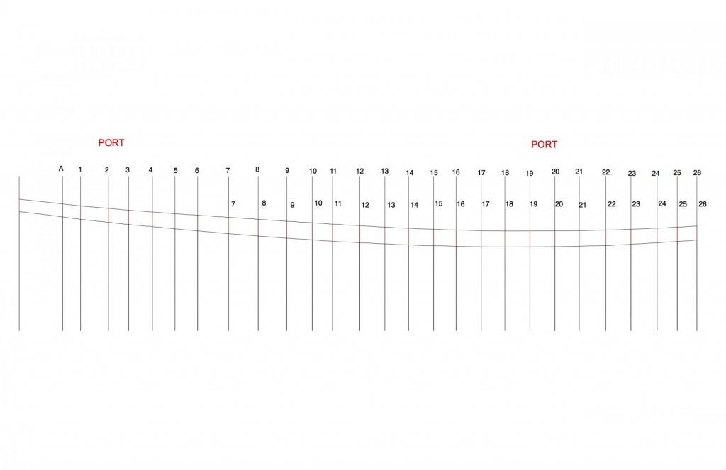
Part 23 – Hull Planking – Transom and Wale Planking the hull starts with planking the transom, since the side planks overlap the ends of the transom planks, and the bottom planks butt up against the angle of the transom. Transom planking is pretty straight-forward, as in the following photos. The first side plank to be installed is the sheer plank, or wale (known as ‘the bends’ in the Chesapeake area). It’s hard to determine from the HAER drawings whether this is one plank or is made up of multiple planks. Some of the photos of Kathryn seem to indicate that it is made up of multiple planks, but for the model a single plank is being used. The bottom of the wale also contains what appears to be a bead that is painted red, and in one photo it’s obvious that the wale is somewhat thicker than the rest of the side planks. On the model the wale is 1 inch thicker than the rest of the side planks. The bottom of the wale is shown on the HAER lines plan, and was used along with the bottom of the deck to develop a plan for the plank, as in the following photo. Using a height gauge, the bottom of the wale was marked on each of the frames. The wale on the model is installed in sections approximately 20 feet long. This corresponding part of the drawing was glued to appropriate stock, using a glue stick, and the plank was roughly cut on the scroll saw. The plank was then sanded to the lines using the disk sander for the bottom, or convex, side. The concave side was shaped on the spindle sander. The plank was soaked in boiling water and was then clamped to the hull overnight to allow it to conform to the shape of the hull. The process of shaping, bending, and then gluing the plank took 24 hours for each length of plank. So, after 4 days the installation of the wale was completed. The planksheer will sit on top of the wale and its outer edge will be flush with the wale, so some time was spent in making sure that the top of the wale was even with the deck beams. Kathryn’s chine is rounded, and the plank ends of the side and bottom planking feather into the chine. I’ve been spending some time trying to work out an approach to installing the chine. I’m hoping that this will be completed in the near future, and that will likely be the subject of the next post. Thanks everyone!


- 878 replies
-
- 19
-
-
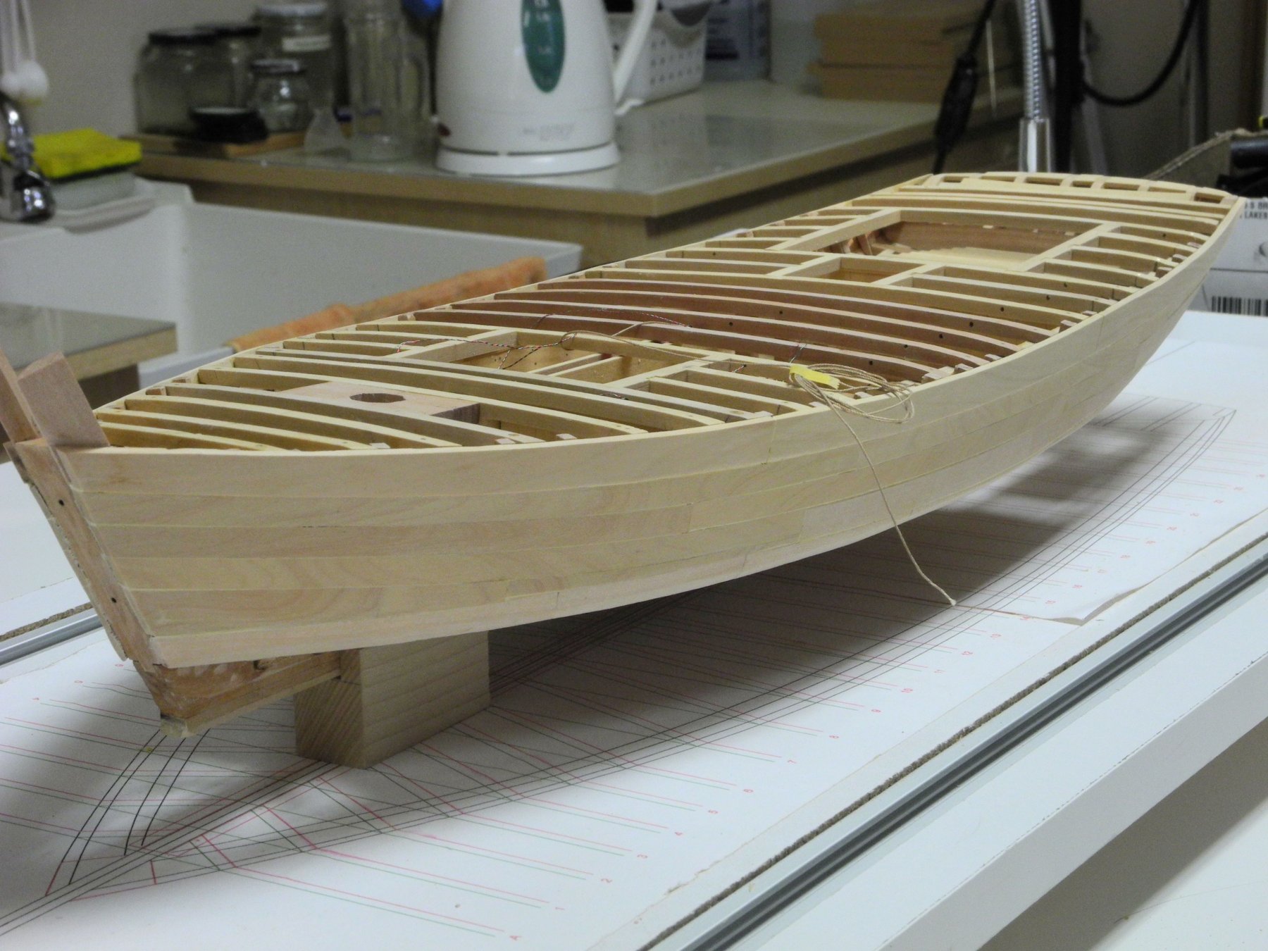
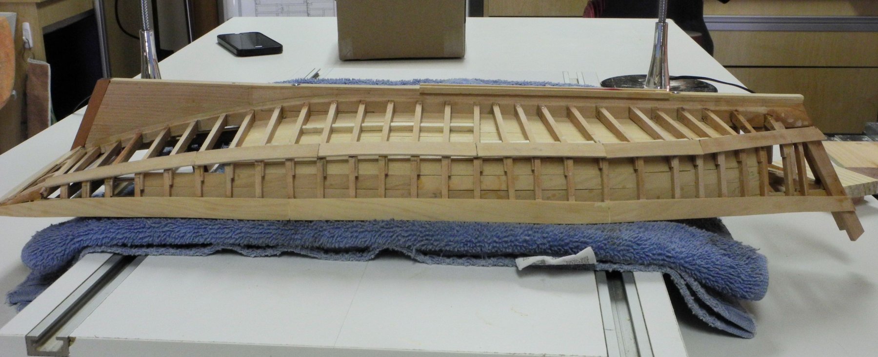
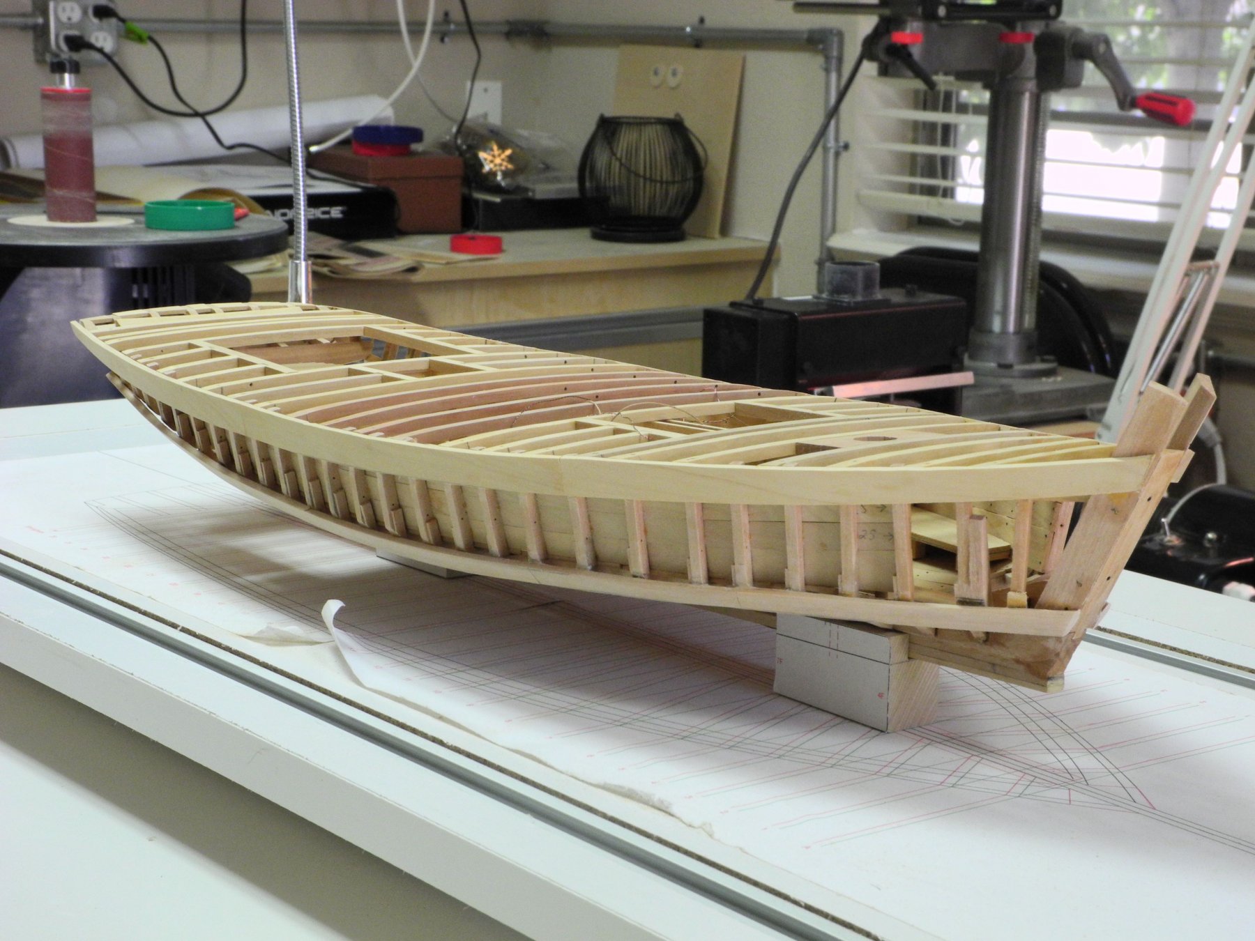
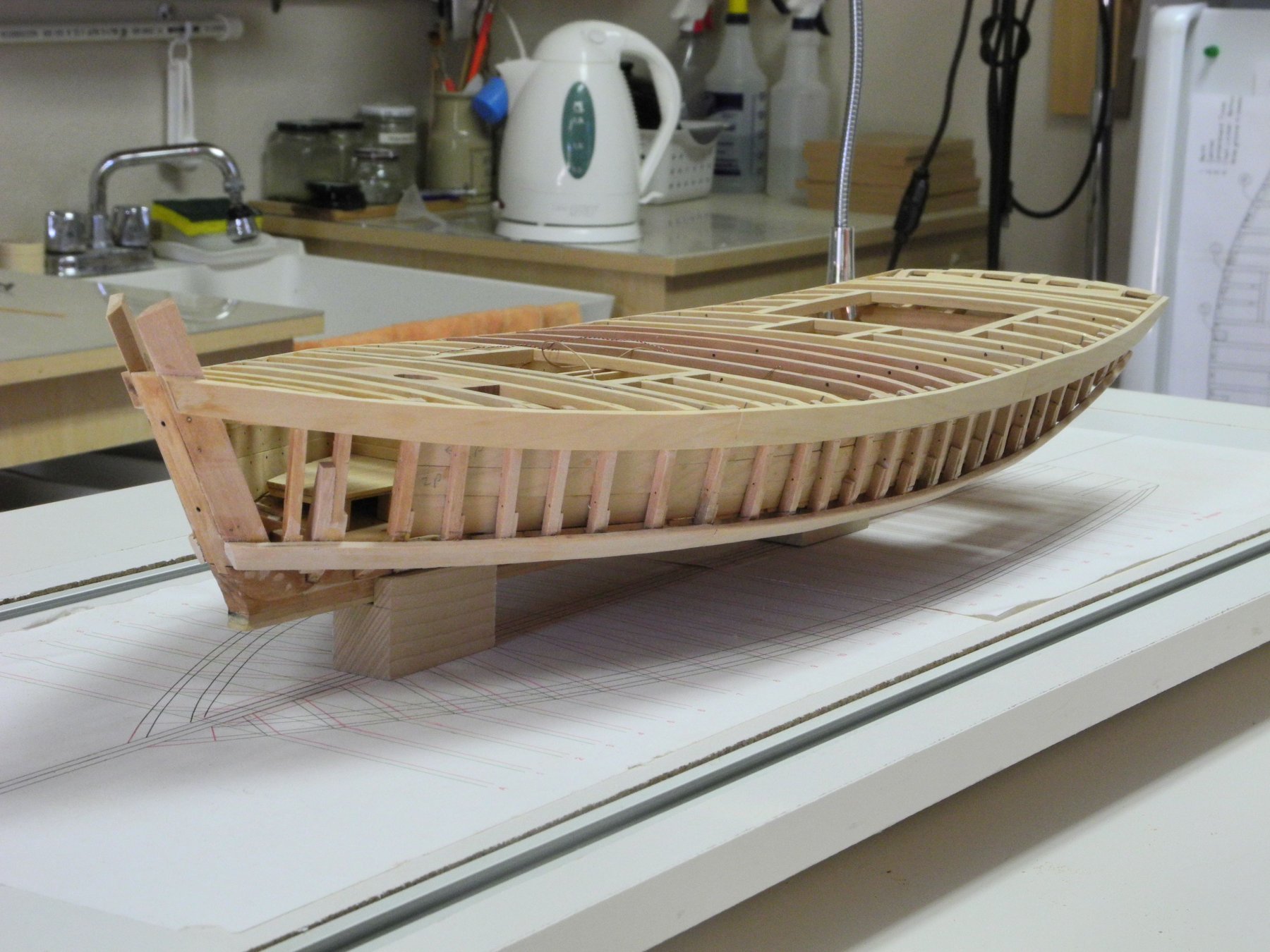
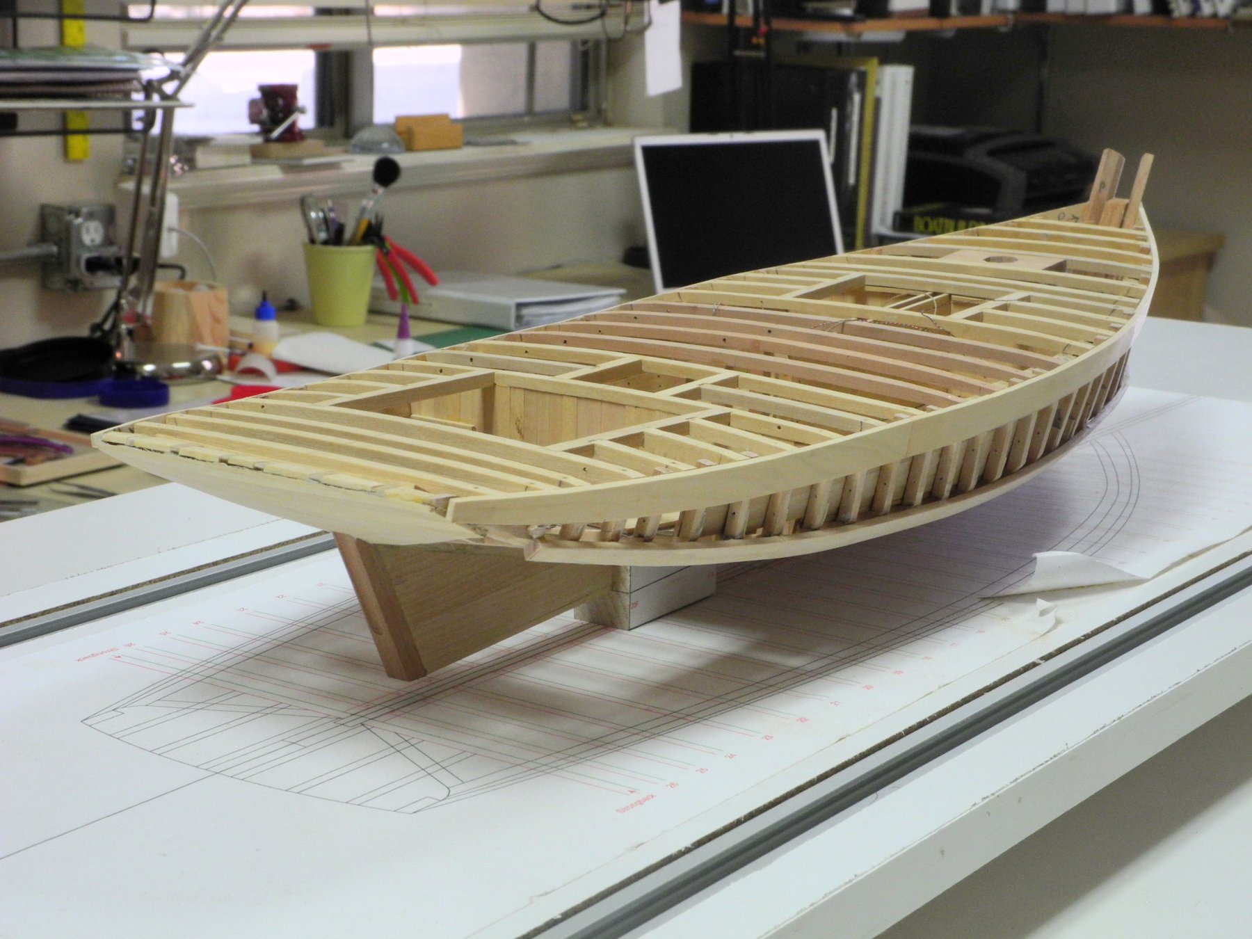
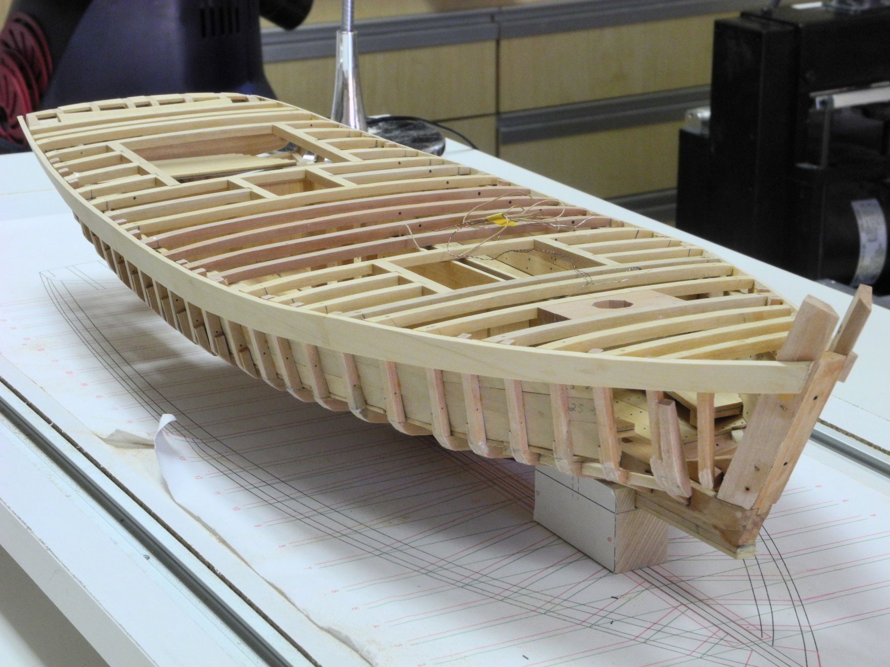
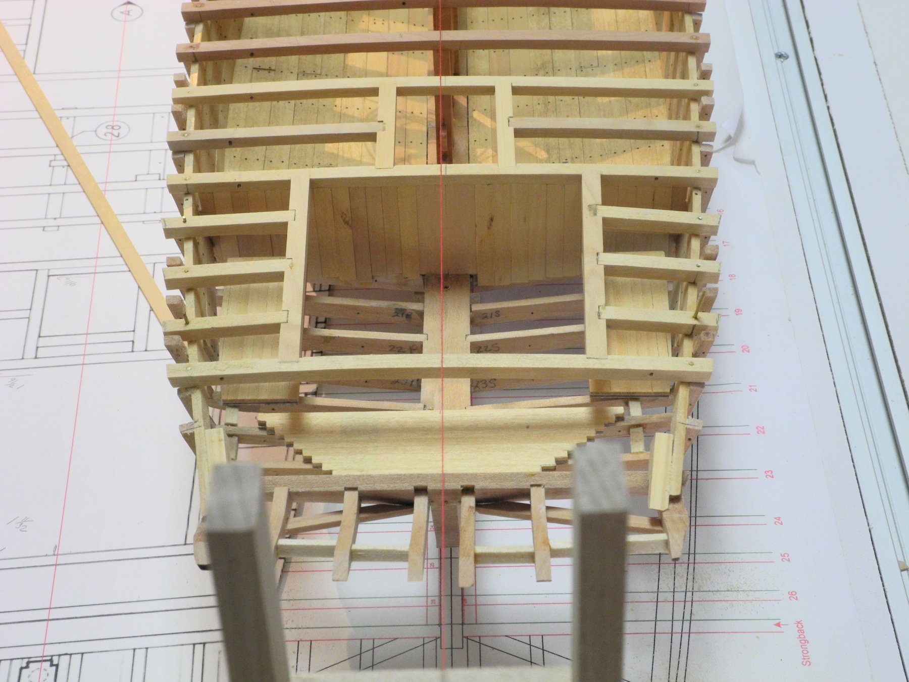
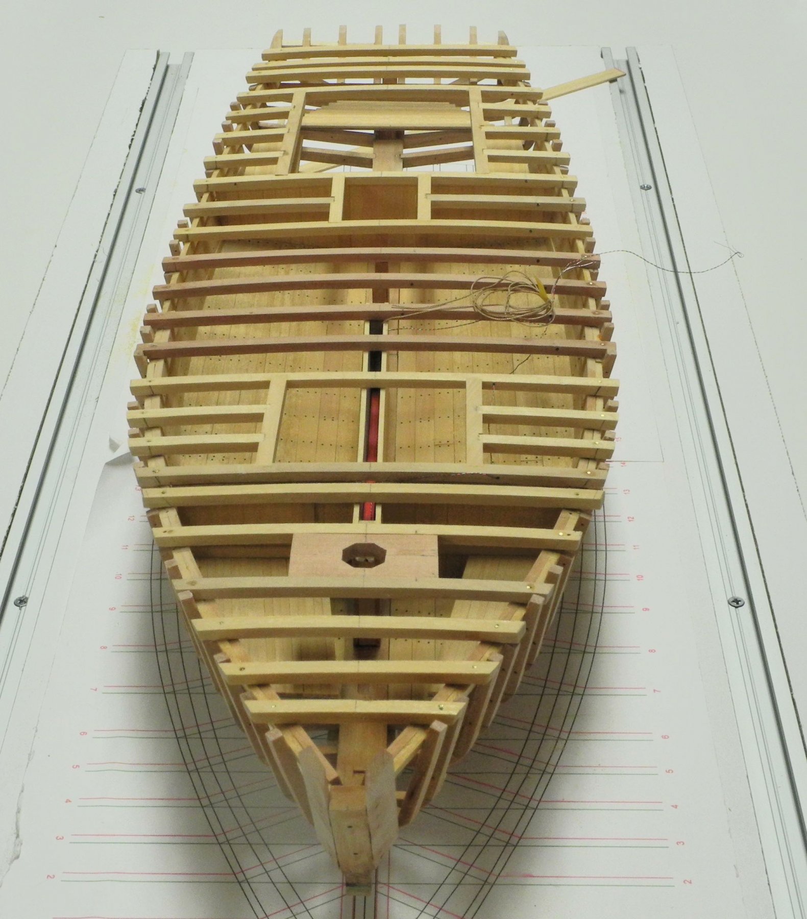
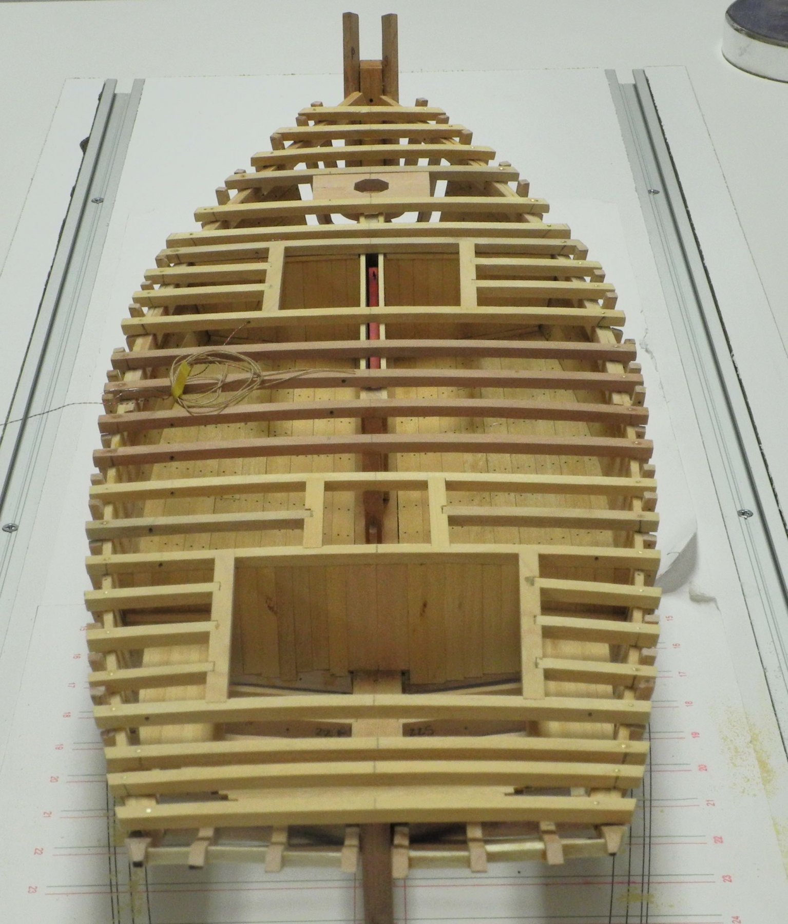
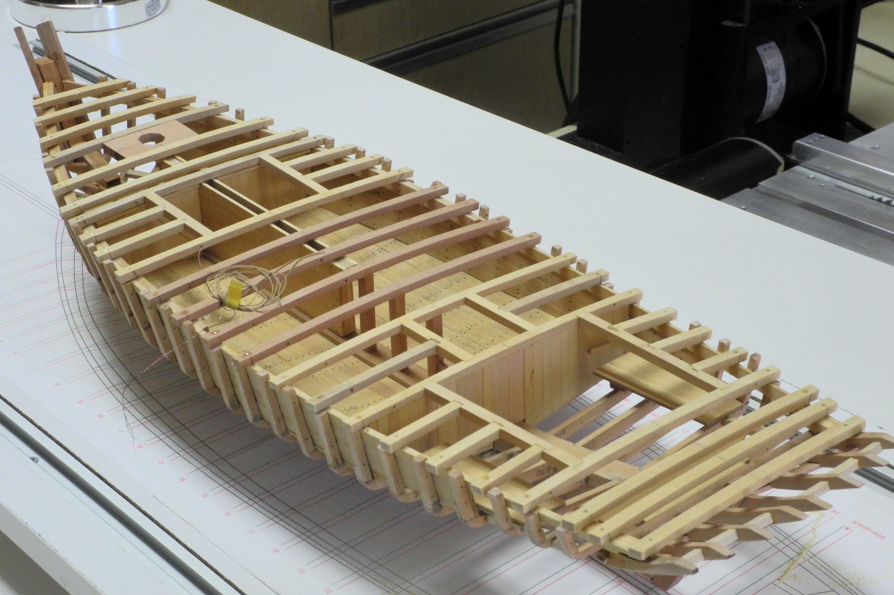
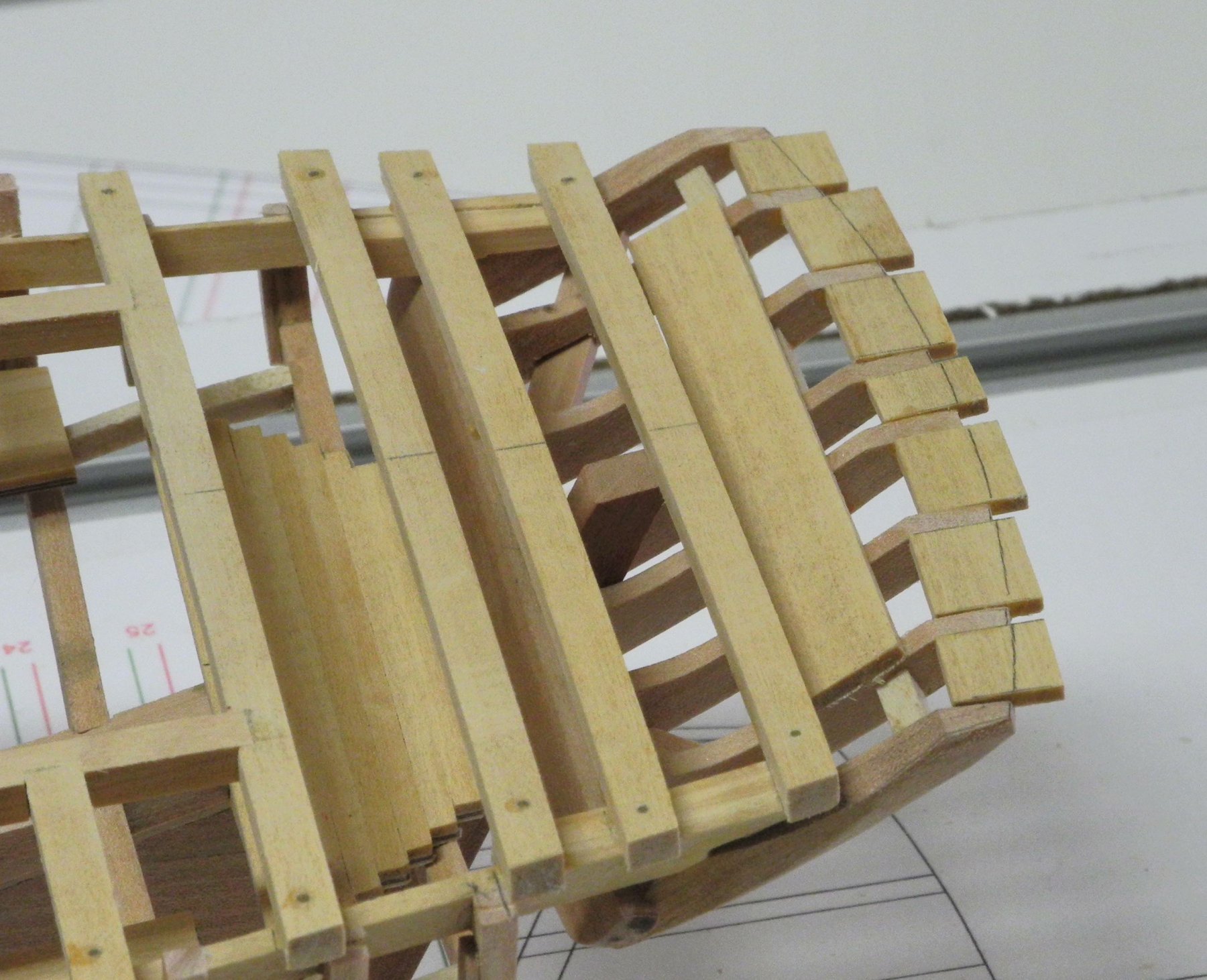
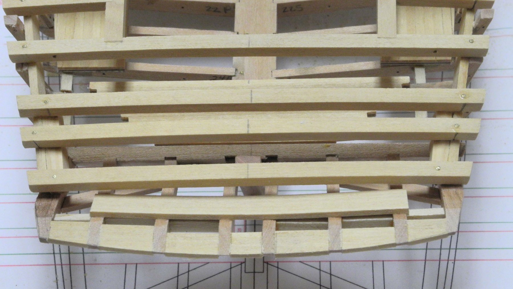
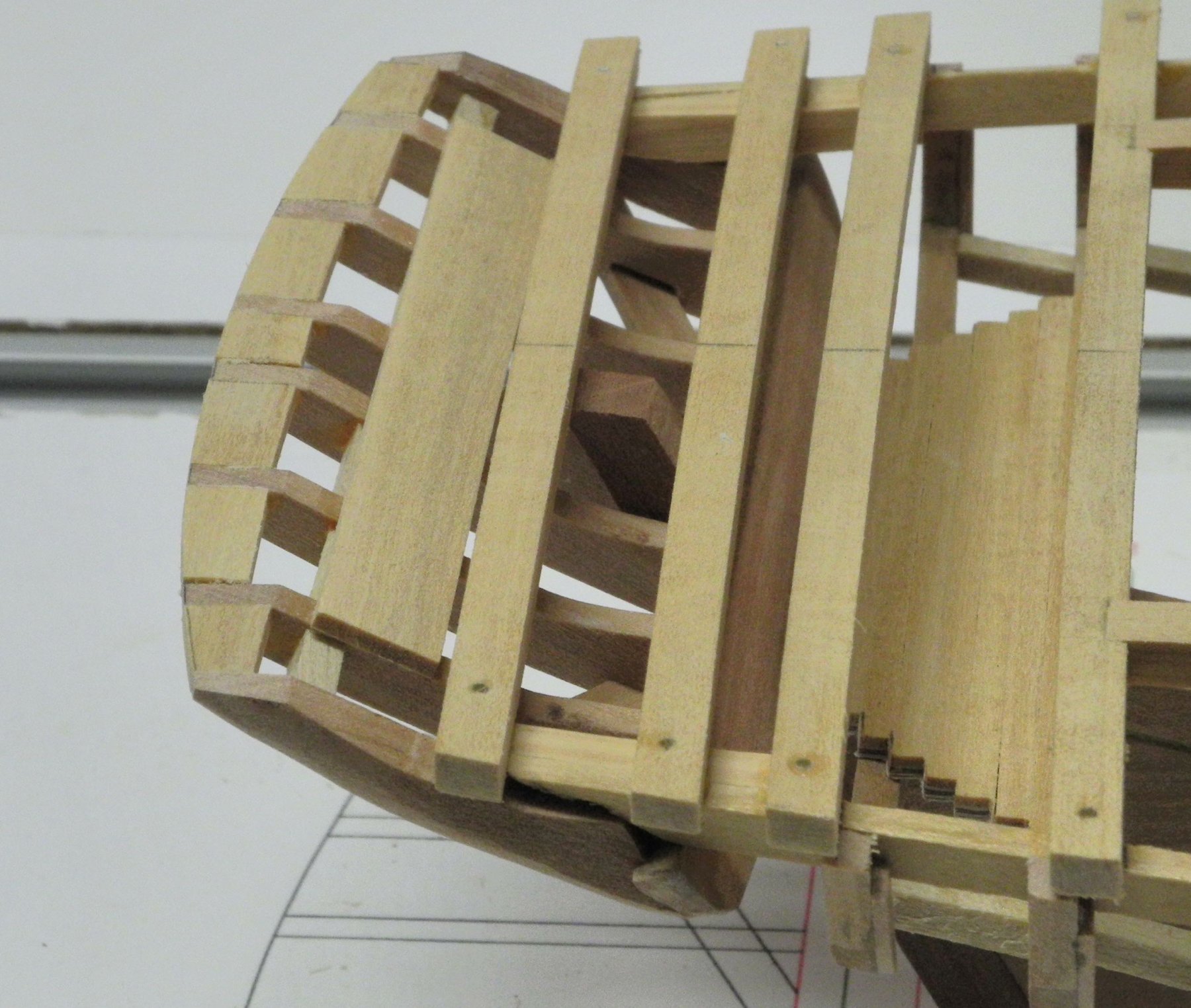
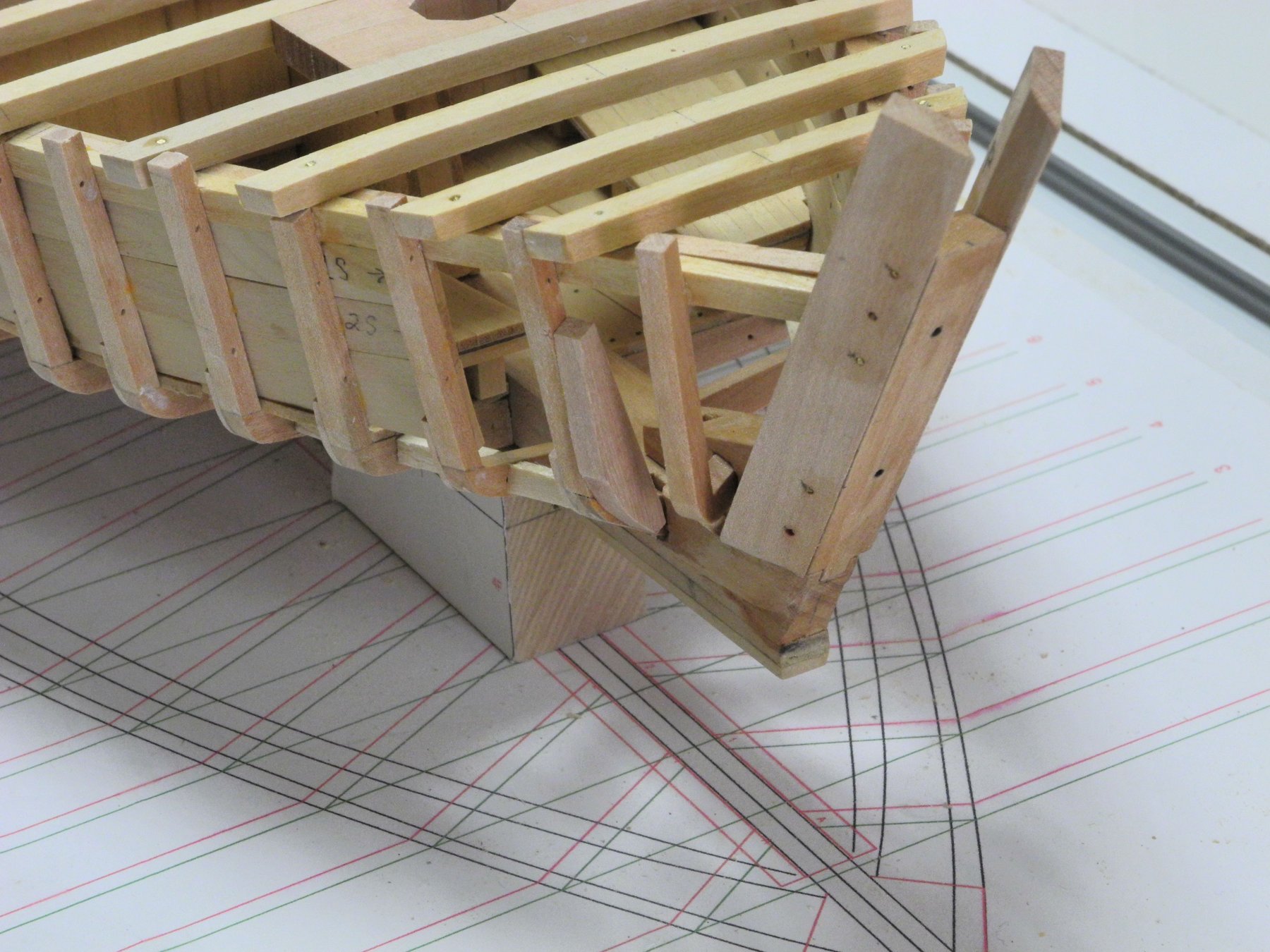
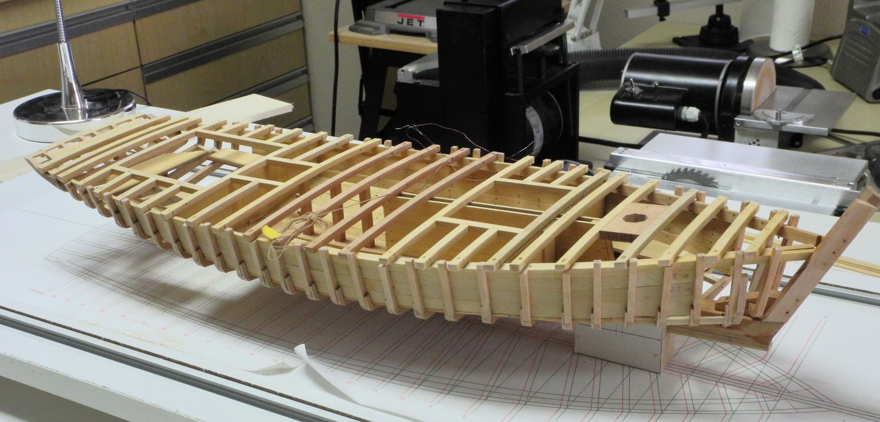
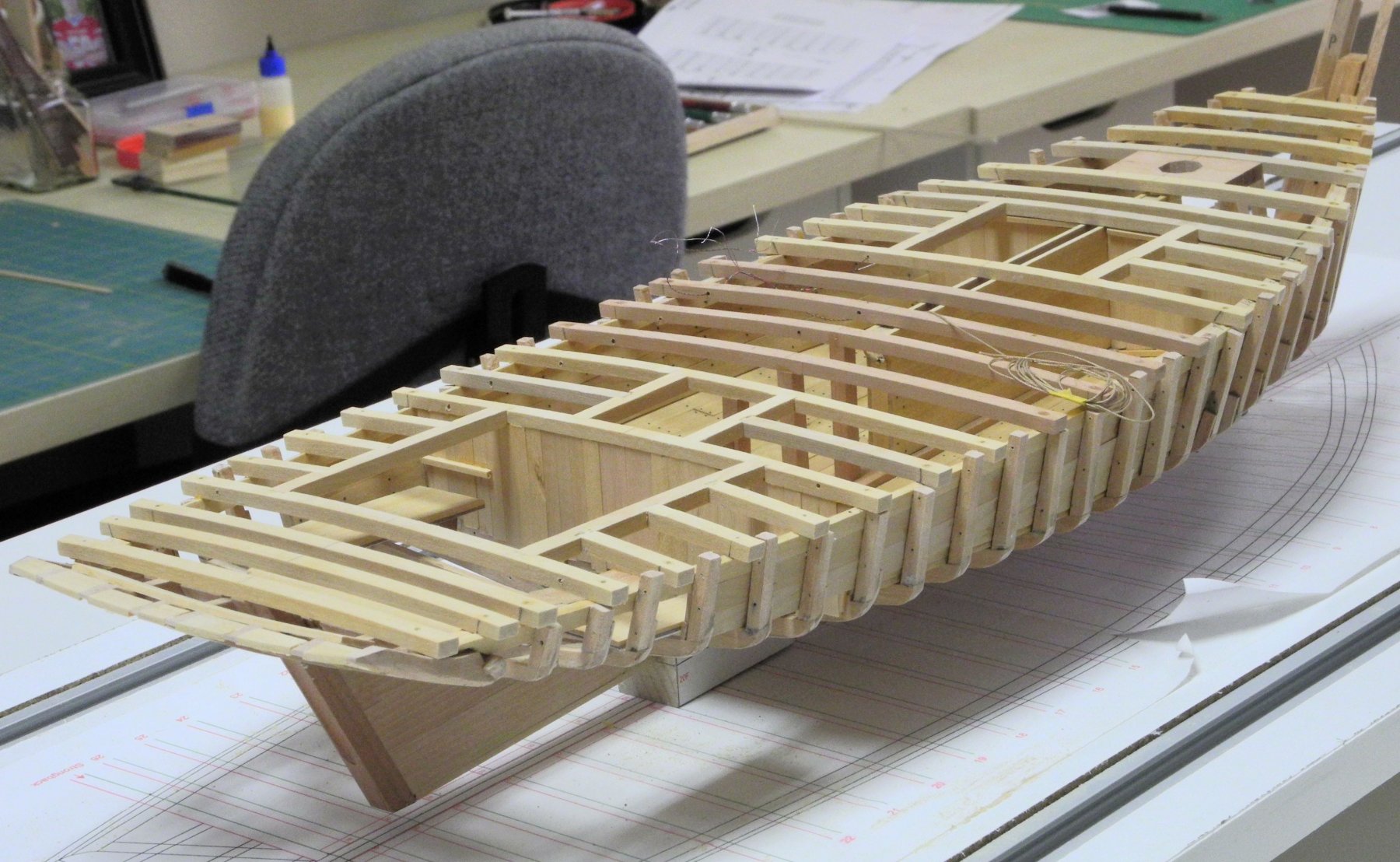
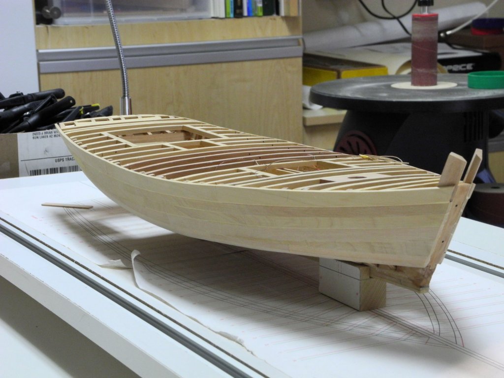
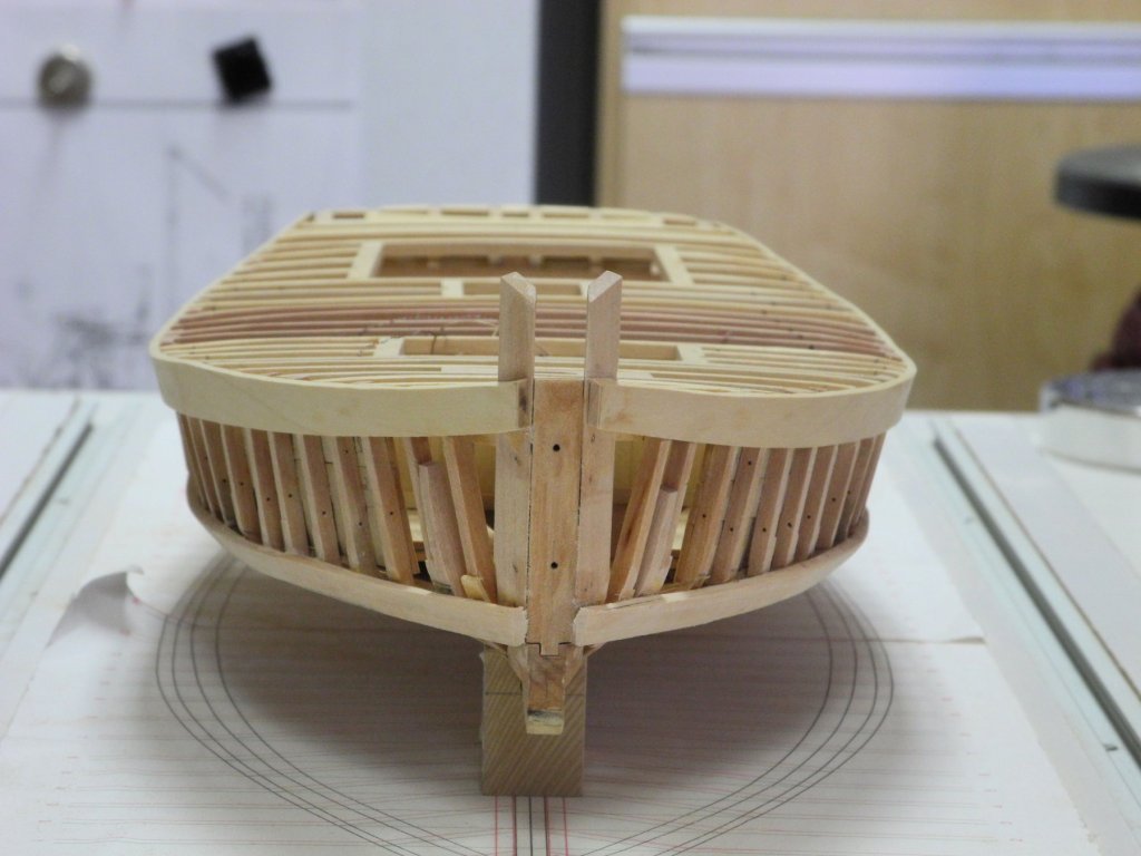
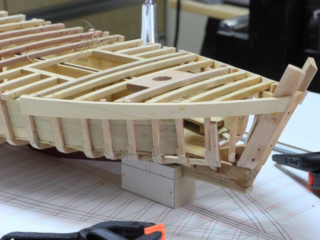
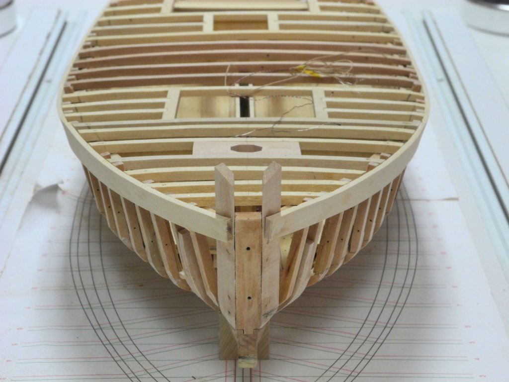
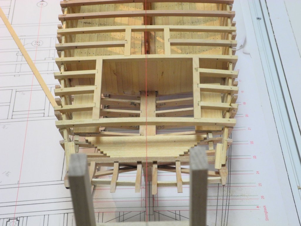
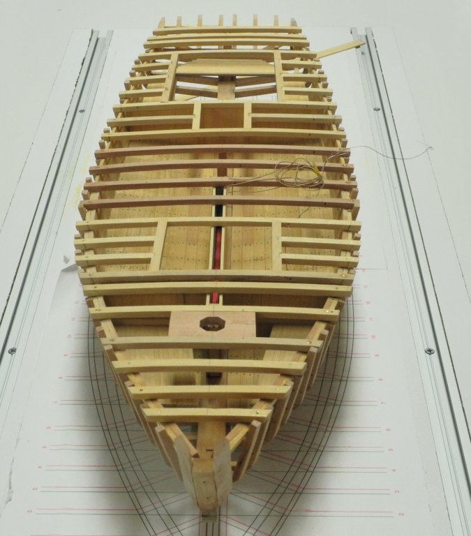
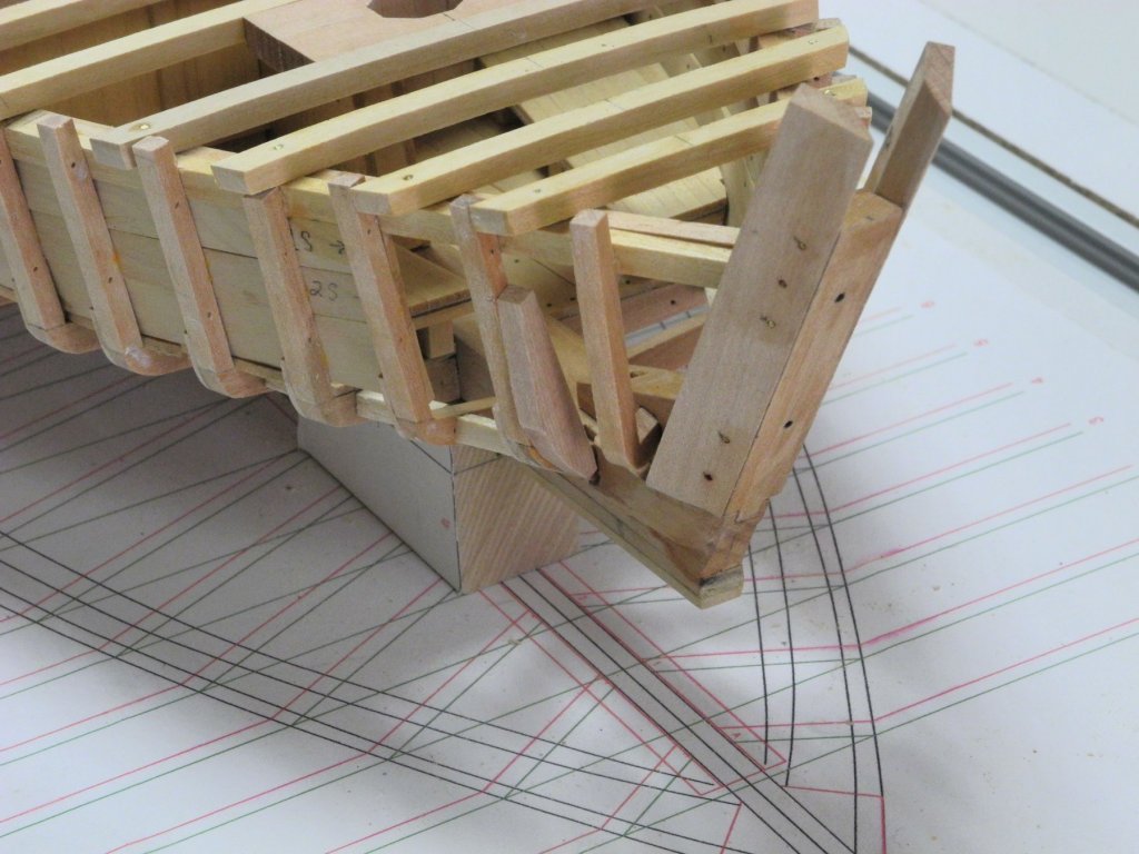
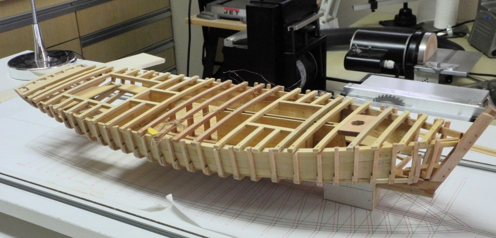
Part 22 – Preparing for Hull Planking In the last post I indicated that cabin installation would be the next work, since the half beams on each side of the cabin would interfere with some of the cabin installation work. In actuality, the only interference would be with the installation of the 3 berths located in the cabin, since these are located under the half beams and under a couple of the deck beams aft of the cabin. In addition, installing the cabin itself prior to hull planking would not be a good approach, since the cabin will be fairly delicate and would make it difficult to hold Kathryn for bottom planking. So, the berths in the cabin area were installed. The installation of the remaining deck beams was then completed. Several items needed to be worked on in preparation for the hull planking. First, a stiff plank was installed across the stern timbers. The purpose of this plank is to pull two of the stern timbers into line with the others. Second, filler pieces needed to be installed between the stern timbers at the deck level. The following photo shows the stiffening plank (the plank that lies at an angle) and the unshaped filler pieces. The filler pieces were shaped using a stump cutter on the rotary tool as in the following photo (apologies for the out-of-focus shot), and then were finish-sanded to the line drawn on the stern. The stern is ready for hull planking. In examining Kathryn’s hull off the shipway, it became apparent that frame number 2 would not allow a plank to lie properly in the chine area. Since reducing this frame would probably weaken it too much, an additional piece of wood was secured to the frame on each side. This will allow cutting down the frame. Kathryn is now ready for some final fairing, followed by planking. Thanks everyone!


- 878 replies
-
- 21
-