Mahuna
-
Posts
1,504 -
Joined
-
Last visited
Content Type
Profiles
Forums
Gallery
Events
Everything posted by Mahuna
-
 Thanks Patrick and Brian. As much as we enjoyed our travels, it's good to be back to the shop. So much to do, so little time
- 649 replies
-
- 5
-

-
- dunbrody
- famine ship
- (and 2 more)
-
Hi Patrick Magellan looks great - the level of detail is awesome. Time to start thinking about your next project.
-
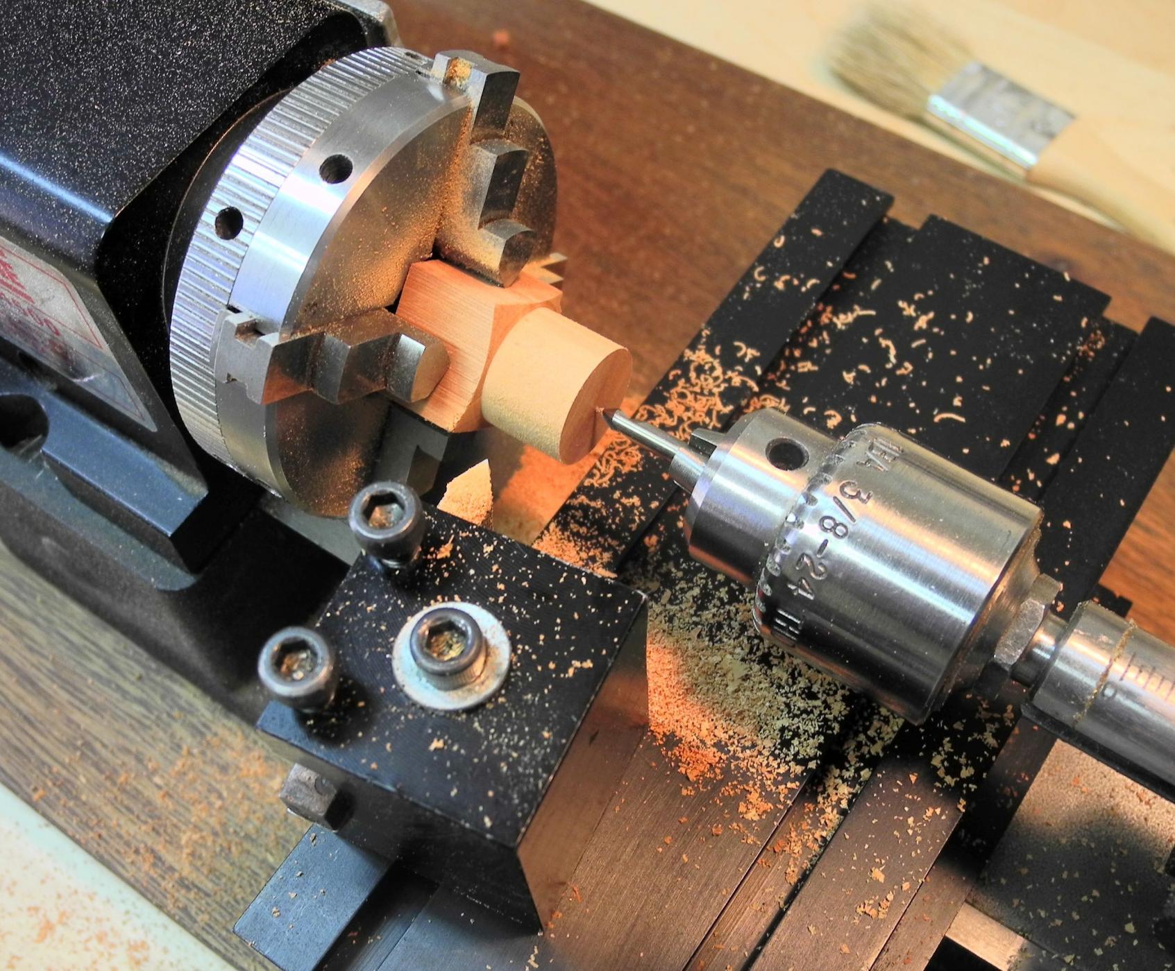
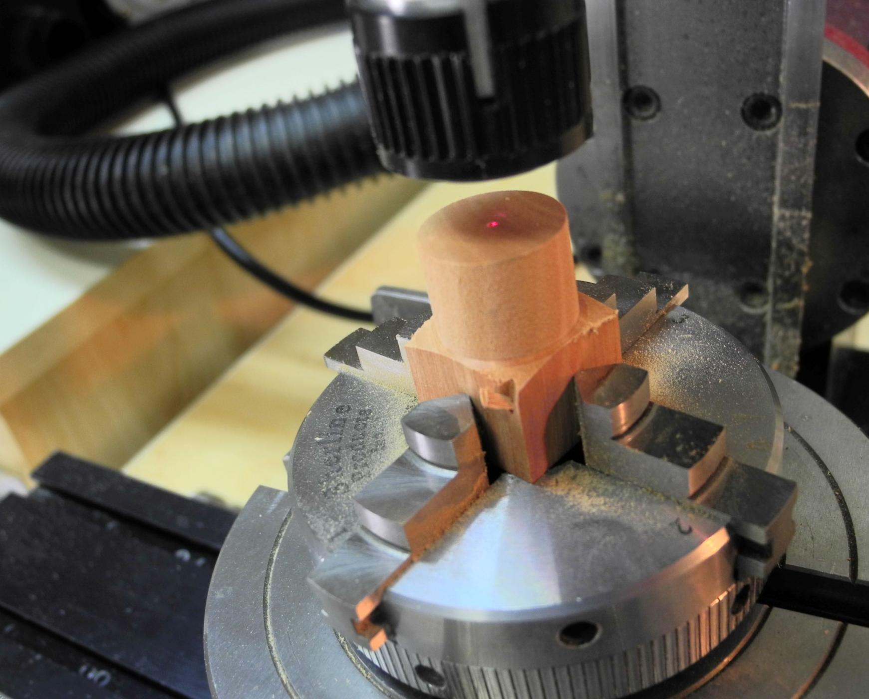
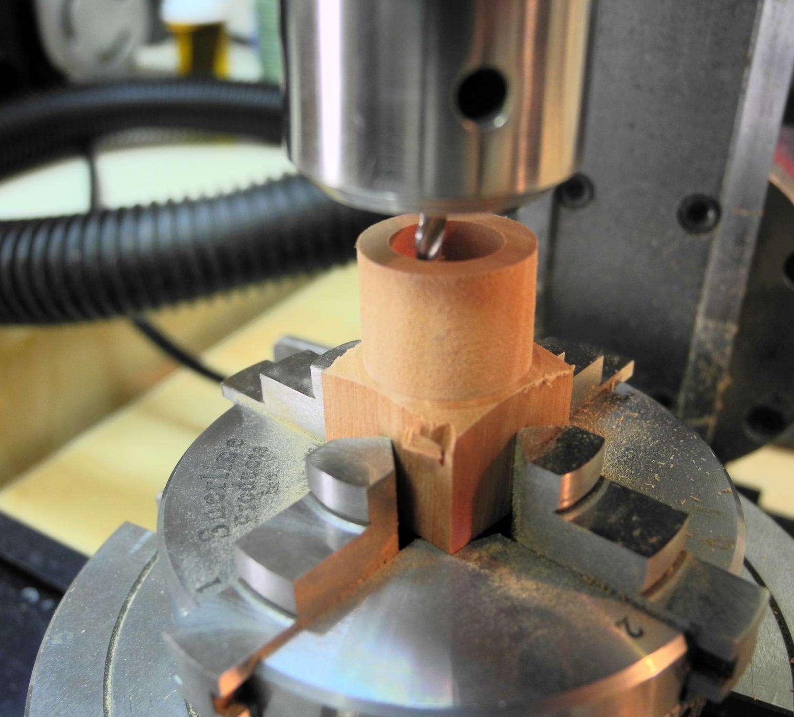
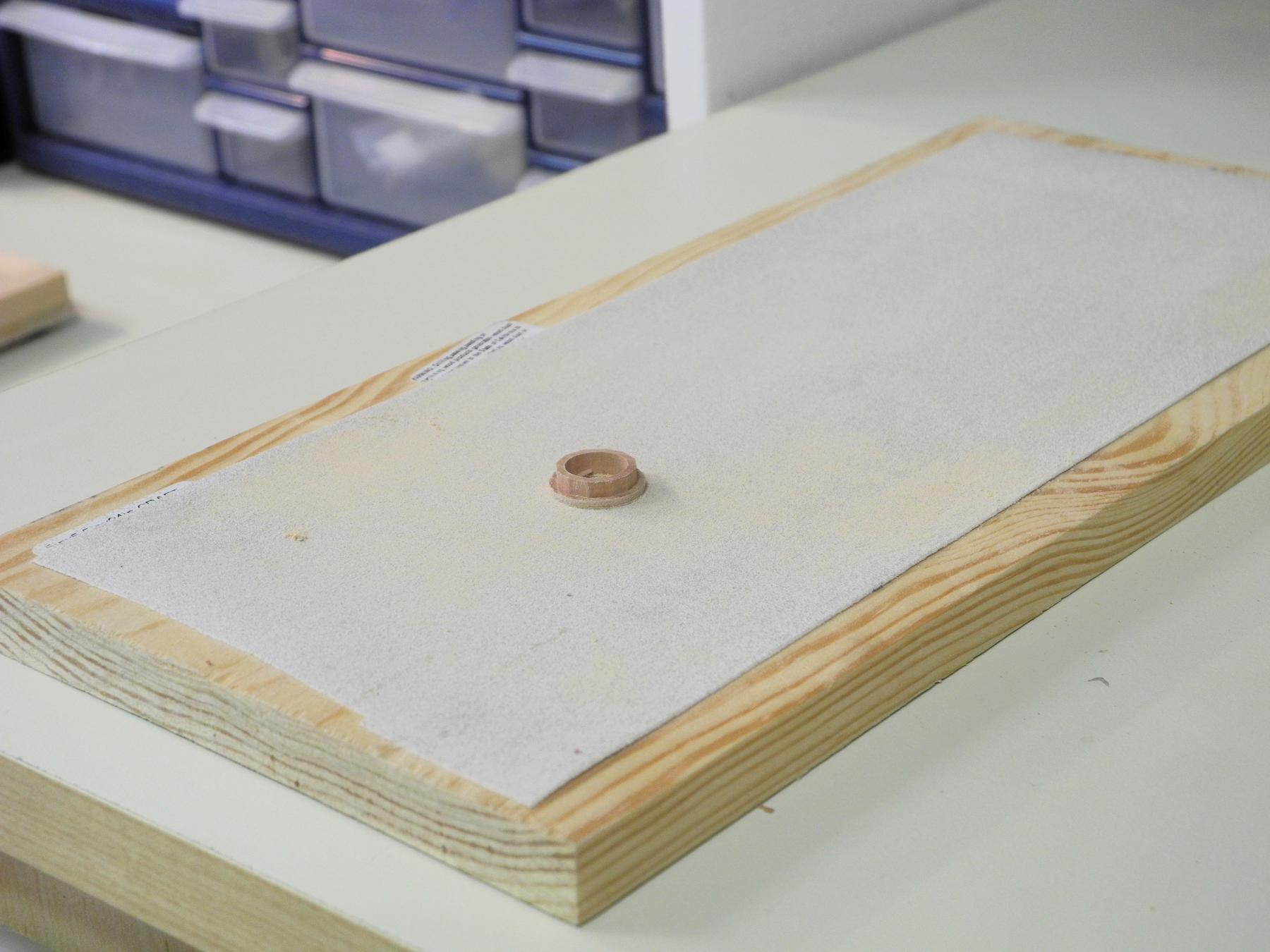
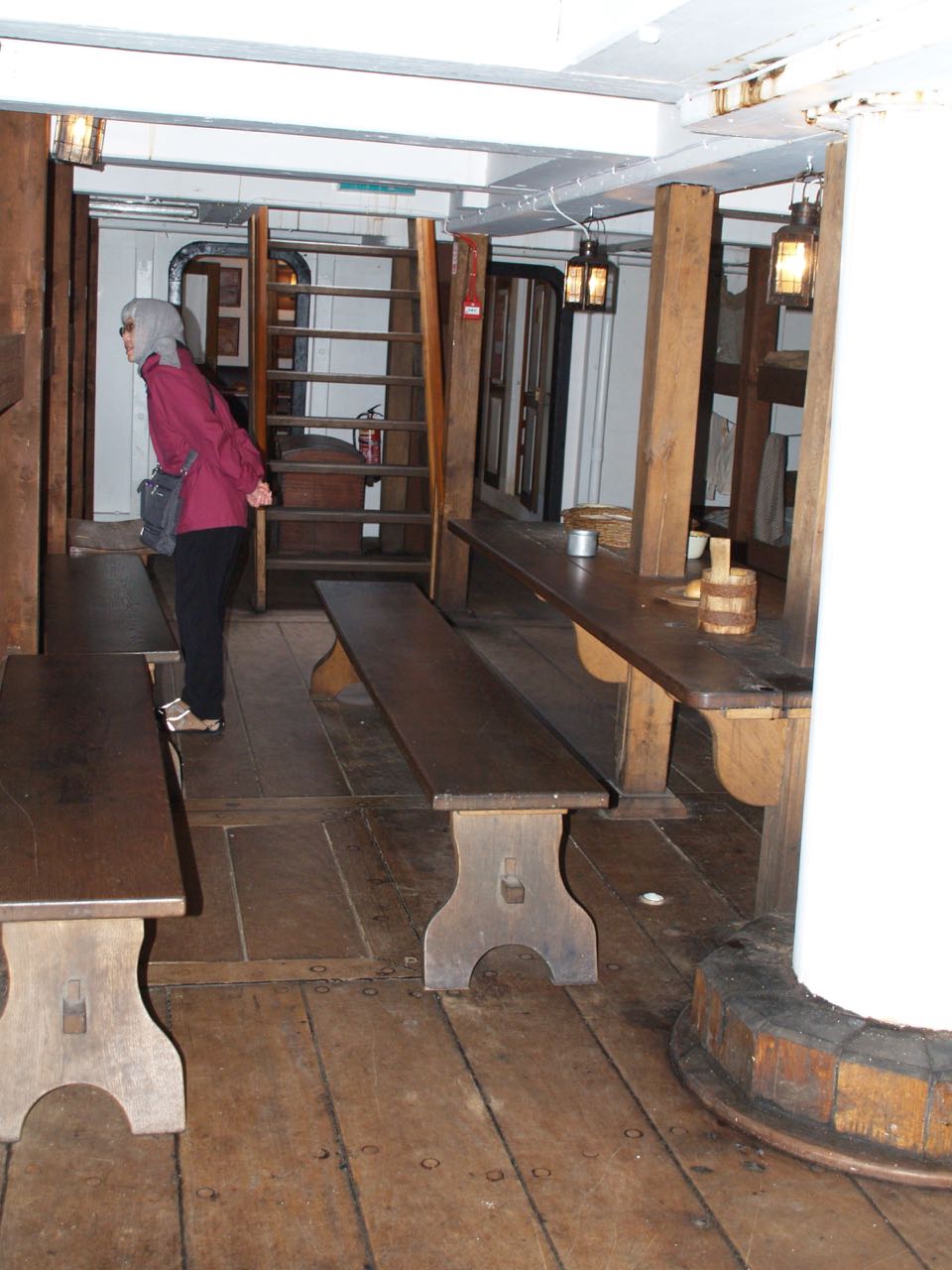
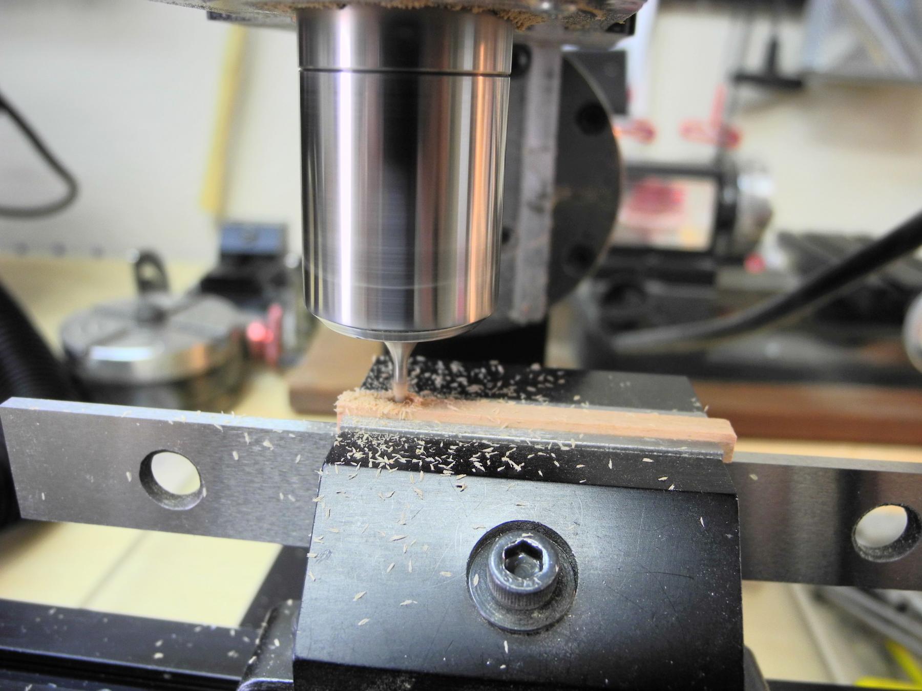
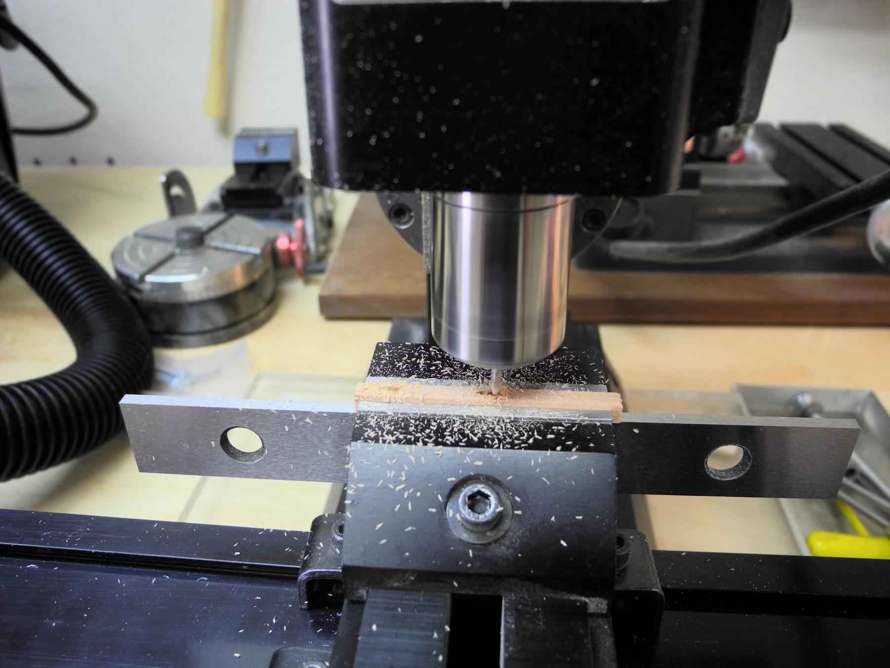
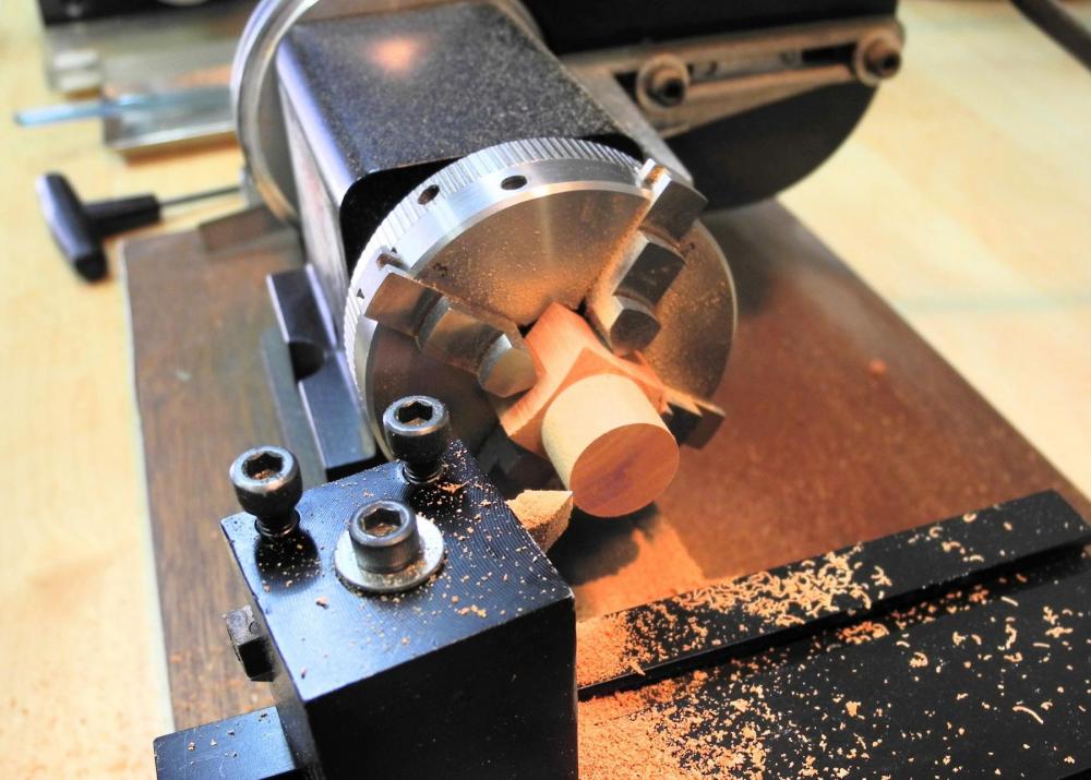
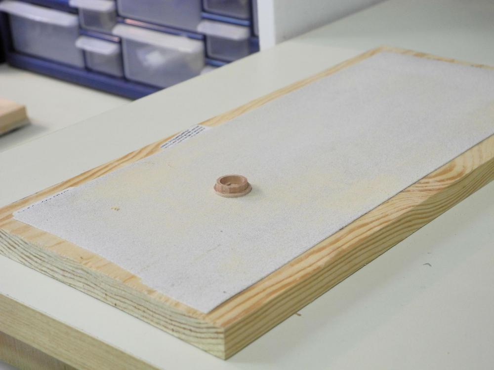
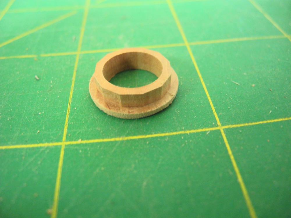
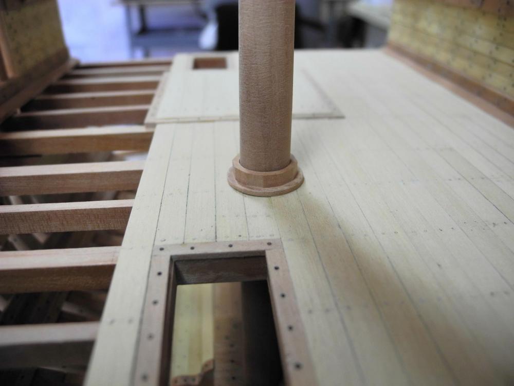
Part 34 – Mast Wedges Hi Everyone – back from vacation and back in the shop. The mast wedges for the Accommodation Deck can be seen in the following photo taken of the actual replica ship in New Ross, Ireland. In the photo it can be seen that there is a rim around the mast wedges, which looks to be approximately one inch thick. The mast wedges for the model will be made out of a single piece of stock. Making the mast wedges begins with turning a piece of stock until it’s the correct diameter. A center hole is then drilled using a very small center drill. The chuck is then transferred to the milling machine. The setup on the milling machine consists of the lathe chuck mounted on top of the rotary table, which is mounted on the tilting angle table. The tilting angle table is set at 3 degrees, which is the angle of the mast rake. The setup is properly centered by aligning the center hole on the workpiece with the axis of the milling head, using the laser center finder. A small end mill was then used to bore down the appropriate distance, and then was used to enlarge the hole to the appropriate diameter for the mast. To accomplish this, the x-axis was locked in place, the y-axis was advanced .025 inches, then the rotary table was turned the full 360 degrees. The y-axis and rotary table movement was repeated until the correct diameter was reached. Unfortunately I neglected to take a photo of the next step (sorry, still recovering from vacation!), which was to lower the tilting table to 0 degrees, center the end mill outside the workpiece on the y-axis, then advance the x-axis for the depth of the chock ends. The outside edge of the wedges was then cut off, the rotary table was advanced 30 degrees, and the cut was repeated. The depth of the cut was calculated to leave a thin rim around the wedges. The final result can be seen in the following photo. I had a slight problem with parting the wedges off the work piece on the lathe. The parting tool shifted, and I was left with a small piece on the bottom of the wedges. I removed this by sanding, using some sand paper glued to a flat piece of plywood. The mast wedges were then slid down the mast, and lightly cleaned up with a round file until they fit properly. In fitting the wedges I discovered that the mast was not properly tapered – there was a slight high spot that the wedges needed to clear before reaching the deck – this left a very slight gap between the wedges and the mast that is visible in the photo, but not at actual size. Once the mast wedges were completed, the mast stub was cut down to its final size of approximately 7 ft at the main deck. None of these pieces has been glued in place, since there is a lot of work that still needs to take place in that area and working around the mast would be an issue. Thanks everyone. It feels good to be back to work on Dunbrody. I’m not sure how much progress I’ll make while the Olympics are on TV, but I’ll keep on plugging away.


- 649 replies
-
- 22
-
-
- dunbrody
- famine ship
- (and 2 more)
-
Looking forward to getting an autographed copy at the San Diego NRG Conference!
- 641 replies
-
- 4
-
-
- greenwich hospital
- barge
- (and 1 more)
-
LOL "Oh well. We can't improve, if we don't make mistakes." That must mean I'm improving every day!!
-
Hi Patrick - your work is always amazing. I like the photos with the individual decks and components separated - it shows the amount of planning that needed to be done.
-
Very nice, Glenn - Heroine is looking better and better. I especially like the last photo with the 'overseers' in the background.
-
Thanks Druxey, Patrick, Brian, and Bob - we've been looking forward to this trip for a long time. Lots of driving, but seeing parts of the country that are new to both of us. Thanks Glenn. I'm learning as I go along.
- 649 replies
-
- 4
-
-
- dunbrody
- famine ship
- (and 2 more)
-
Hi everyone. We've headed out on a 3-week vacation, so there won't be any Dunbrody updates during that time. I will be online once in a while just to keep up with some of the logs that I follow. Stay well!
- 649 replies
-
- 6
-
-
- dunbrody
- famine ship
- (and 2 more)
-
Hi Patrick: I tend to forget all the tiny hidden details until you take the decks off - awesome!
-
Hi Patrick - it takes a lot of photos to show all the incredible detail. The finish looks great. How do you display your models once they're done? It almost seems like this one should be on a constantly rotating base.
-
Rich, Patrick, and Ken - glad you're finding this build interesting from the standpoint of the living conditions, which was my primary motivation for the model. There are some very good articles on the web about 'steerage' conditions on sailing ships, which is essentially what the emigrants' accommodations were. Dunbrody was a fairly small ship, and it seems that on some of the larger ships the number of steerage passengers was much higher - 500 or more. The physical accommodations were essentially the same. I think the main difference was the passengers themselves - many of the irish emigrants were starving and very sick when they boarded, and the crew did not prepare their food or provide other kinds of services as would be provided on other ships.
- 649 replies
-
- 5
-
-
- dunbrody
- famine ship
- (and 2 more)
-
Hi Bob - yeah, not very user-friendly or comfortable. According to the book by Colin Mudie (the designer of the replica ship) the voyage to Canada took three to eight weeks, depending on conditions. During this time the emigrant passengers were generally confined to the Accommodation Deck and only allowed on the main deck for limited cooking. With 176 people in that small space they probably spent a lot of their awake hours in their sleeping platform - a family of four in a 6x6 space, and many of them seriously ill as well. Lavatory facilities (which I'm currently drafting) consisted of 4 small rooms, each with a simple bucket for waste - ugh.
- 649 replies
-
- 8
-
-
- dunbrody
- famine ship
- (and 2 more)
-
Thanks, Patrick. Mortises were used on the replica ship I visited, so I figured I should mill them. Thanks Ed. Thanks Jack. I never would have tried doing the mortises without a milling machine.
- 649 replies
-
- 5
-
-
- dunbrody
- famine ship
- (and 2 more)
-
Thanks Druxey. No, no mattresses - there weren't any. The emigrants slept on the bare boards if they didn't bring any bedding for themselves - and most were too poor to bring much of anything.
- 649 replies
-
- 6
-
-
- dunbrody
- famine ship
- (and 2 more)
-
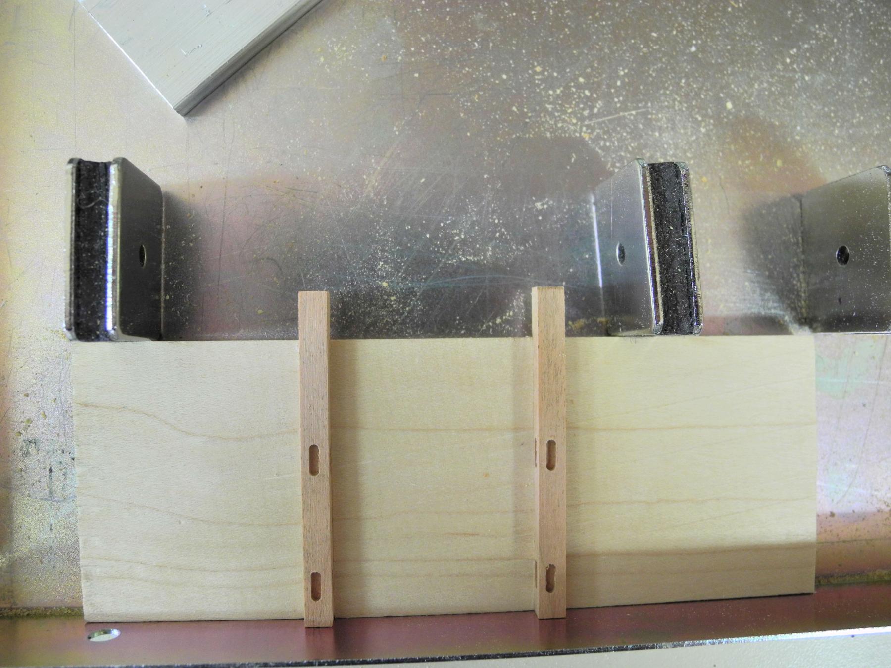
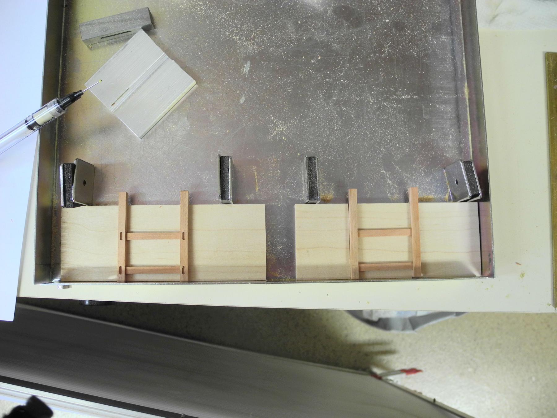
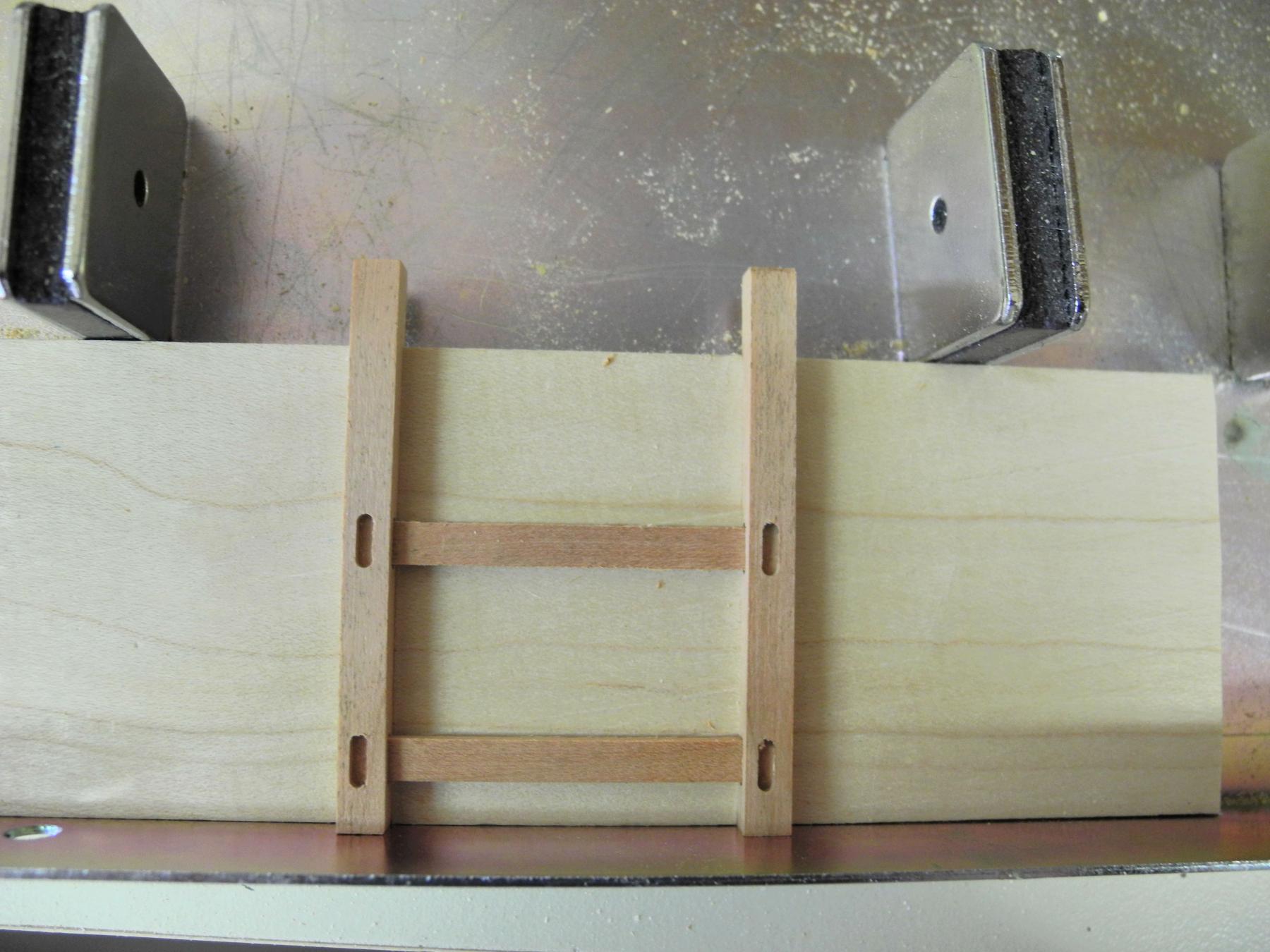
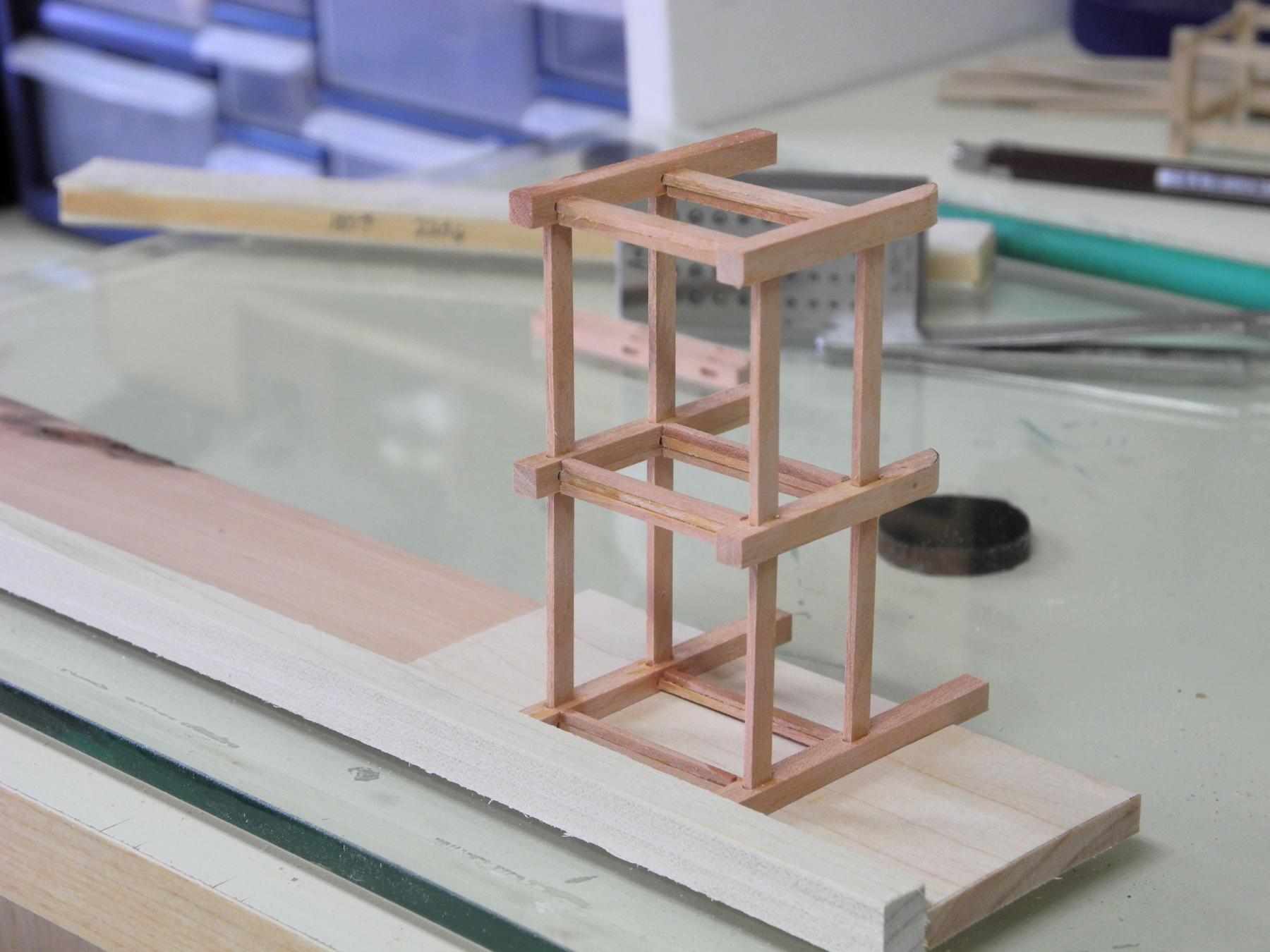
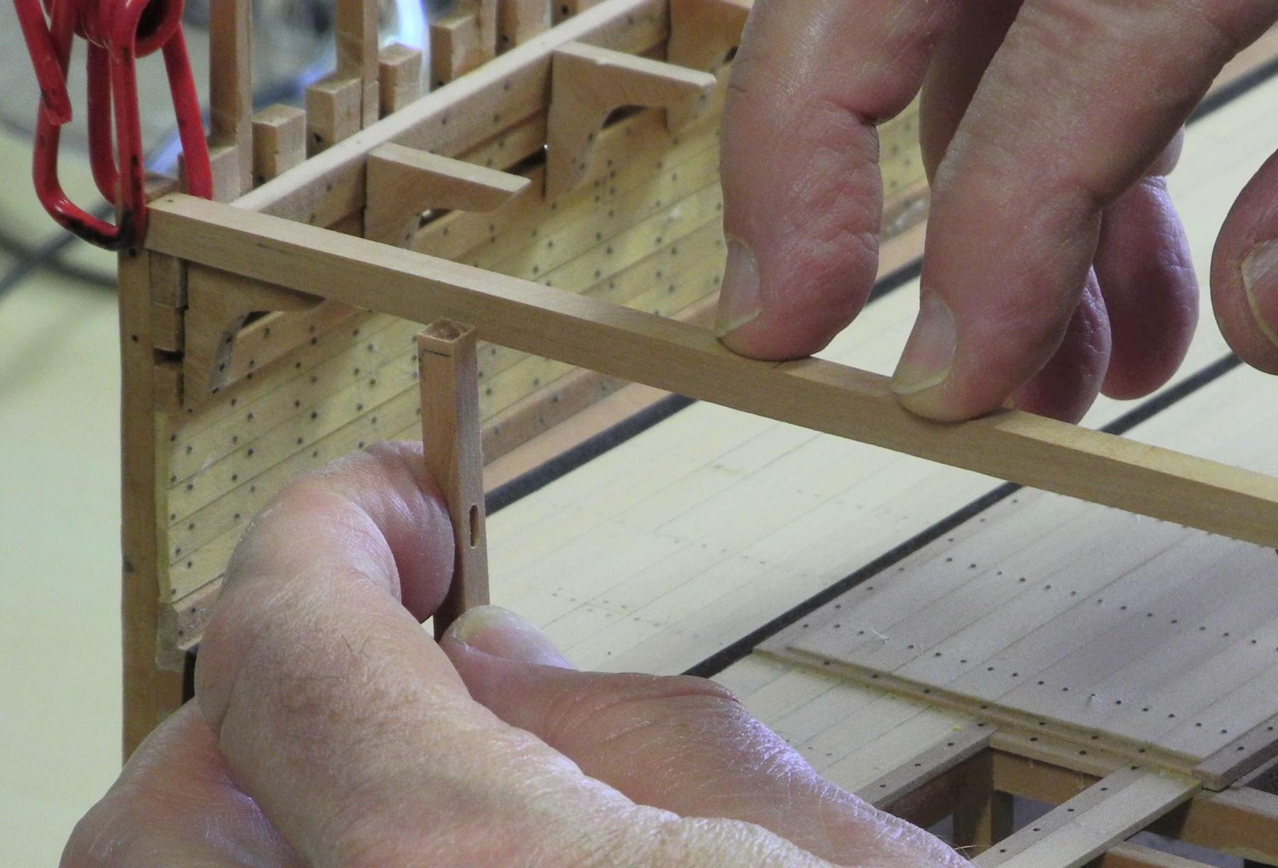
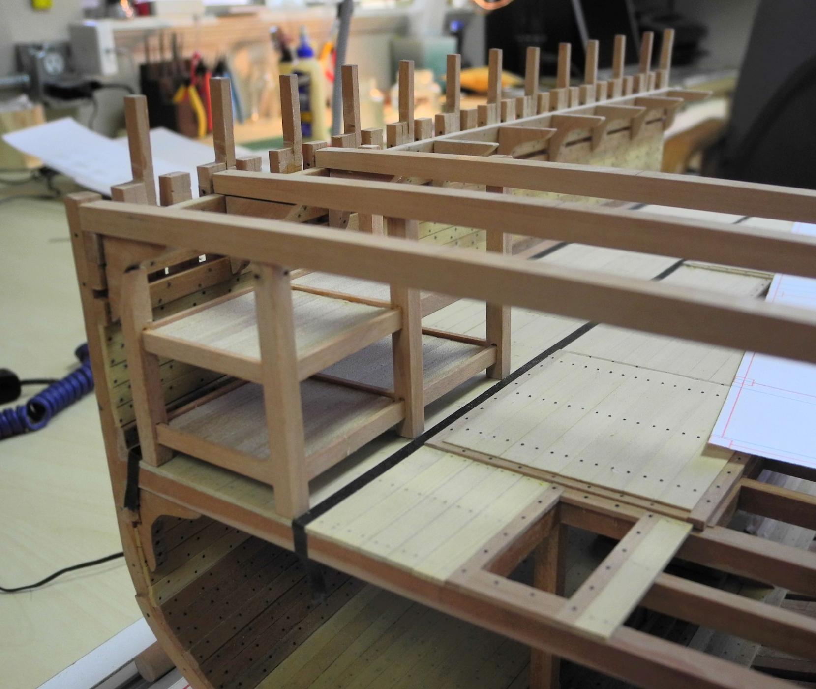
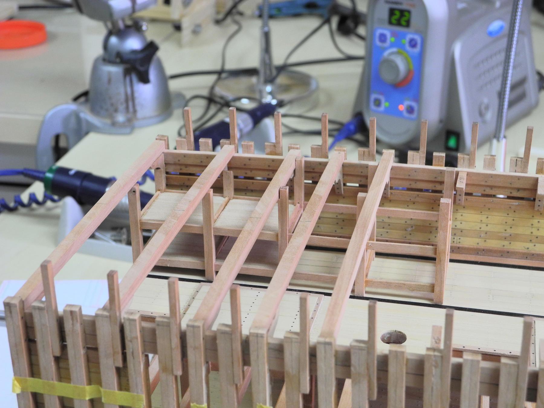
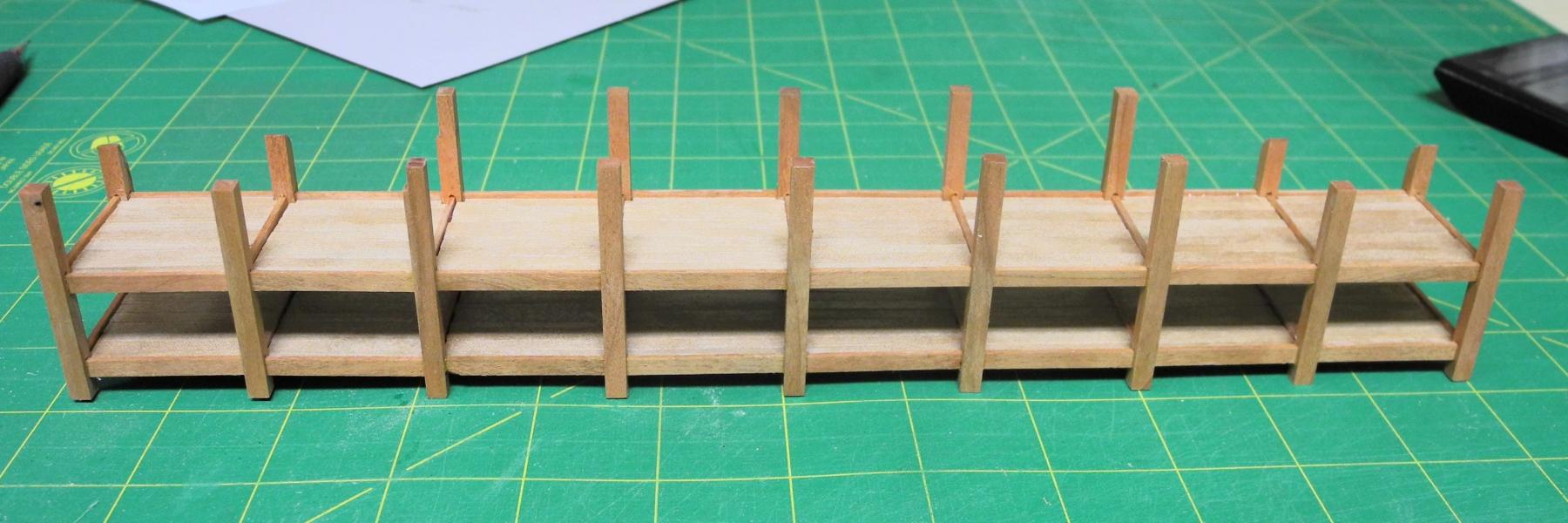
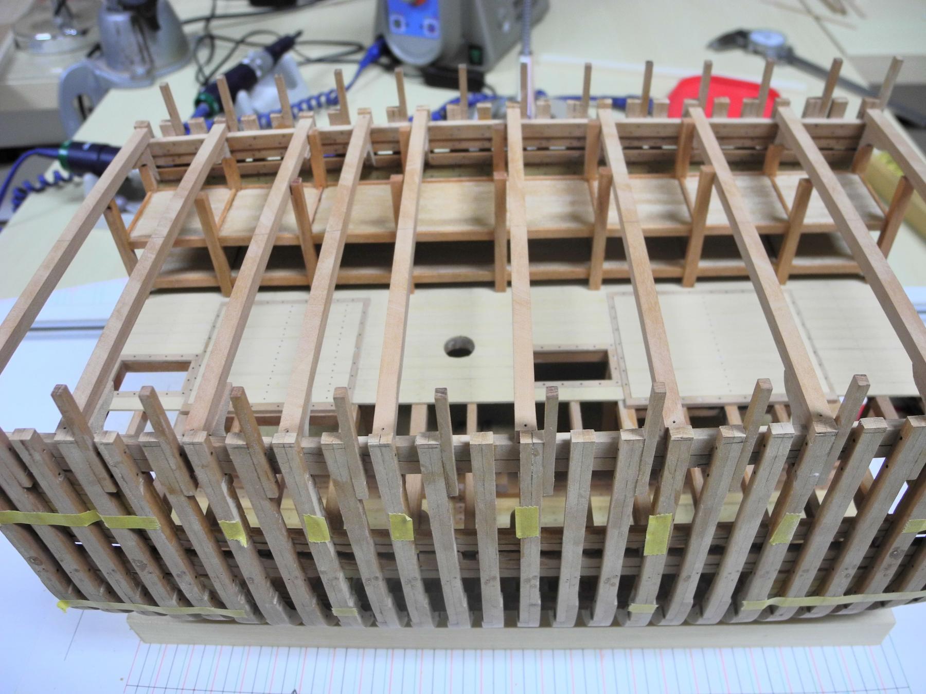
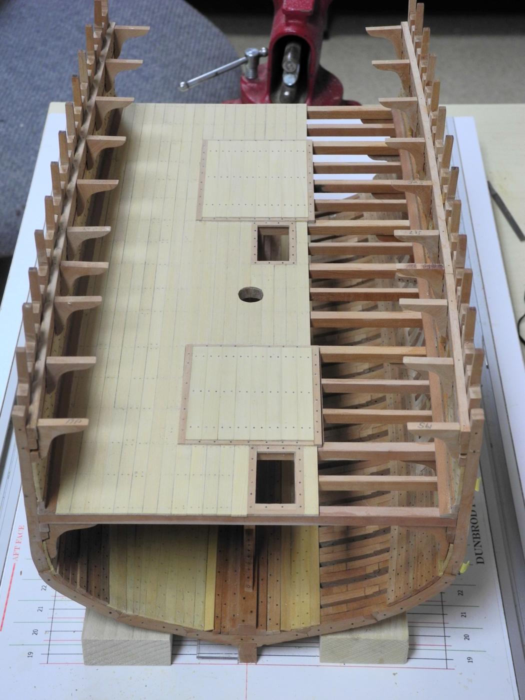
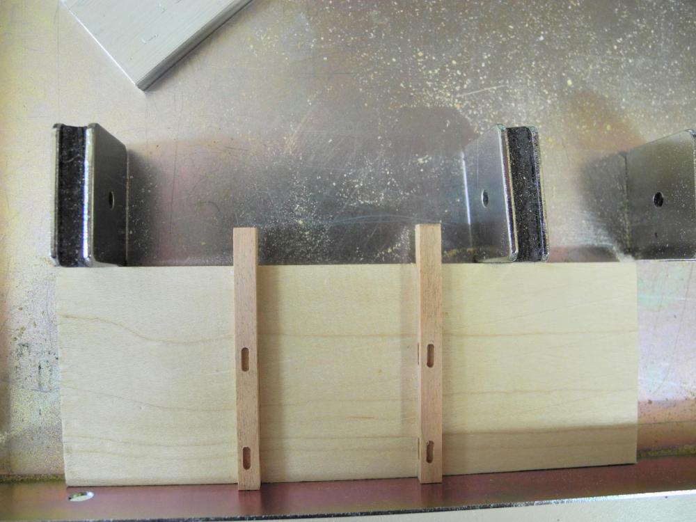
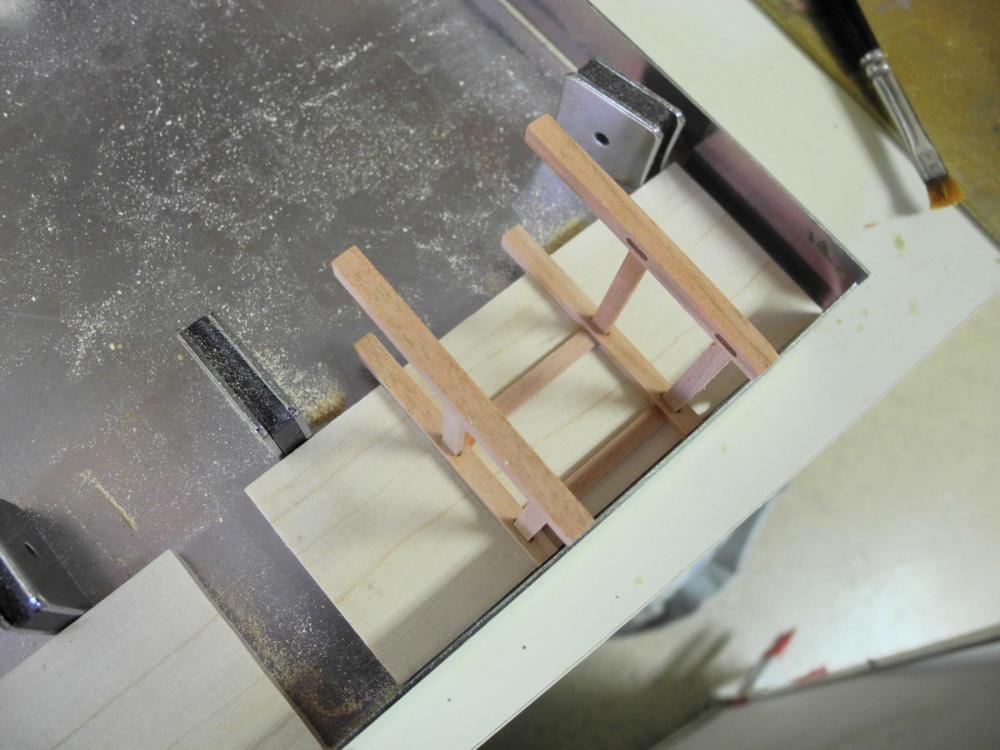
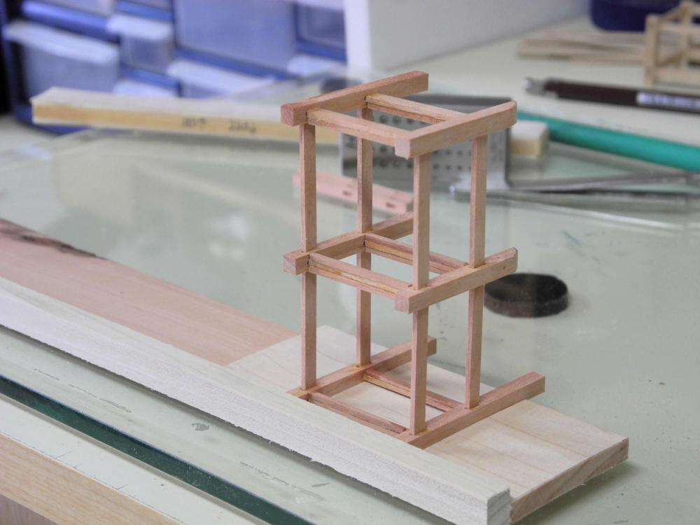
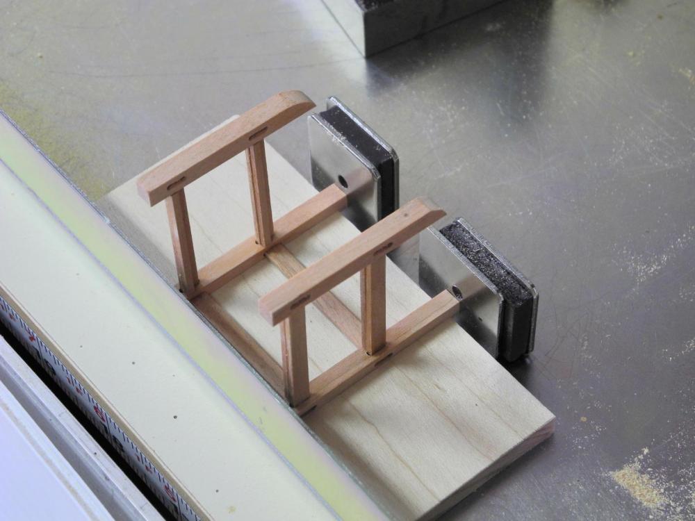
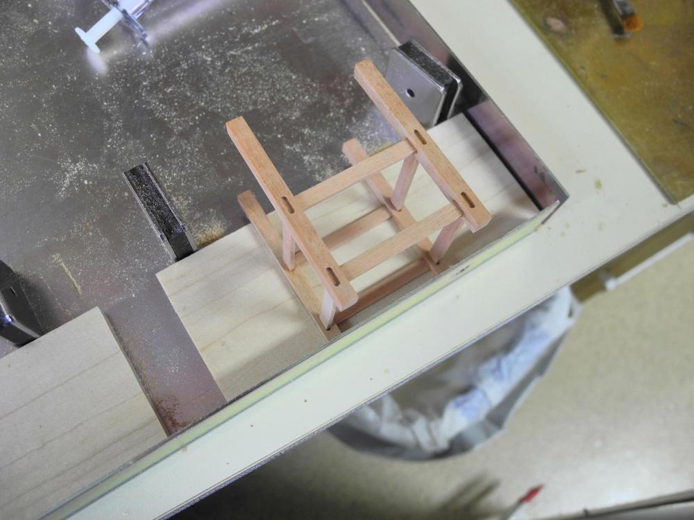
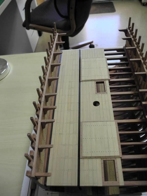
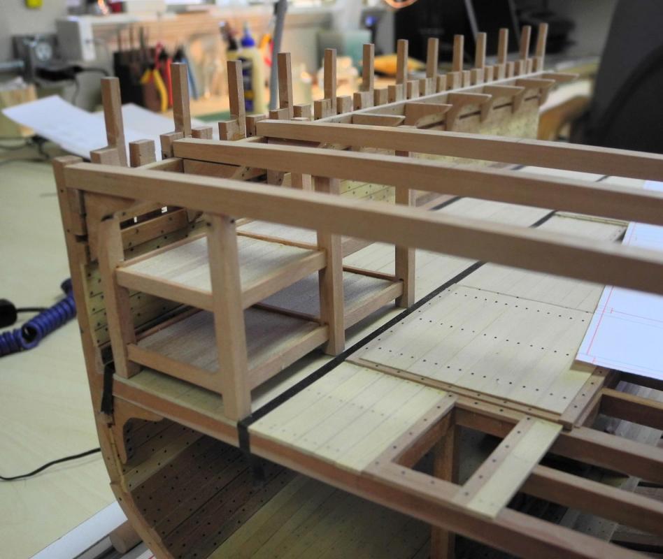
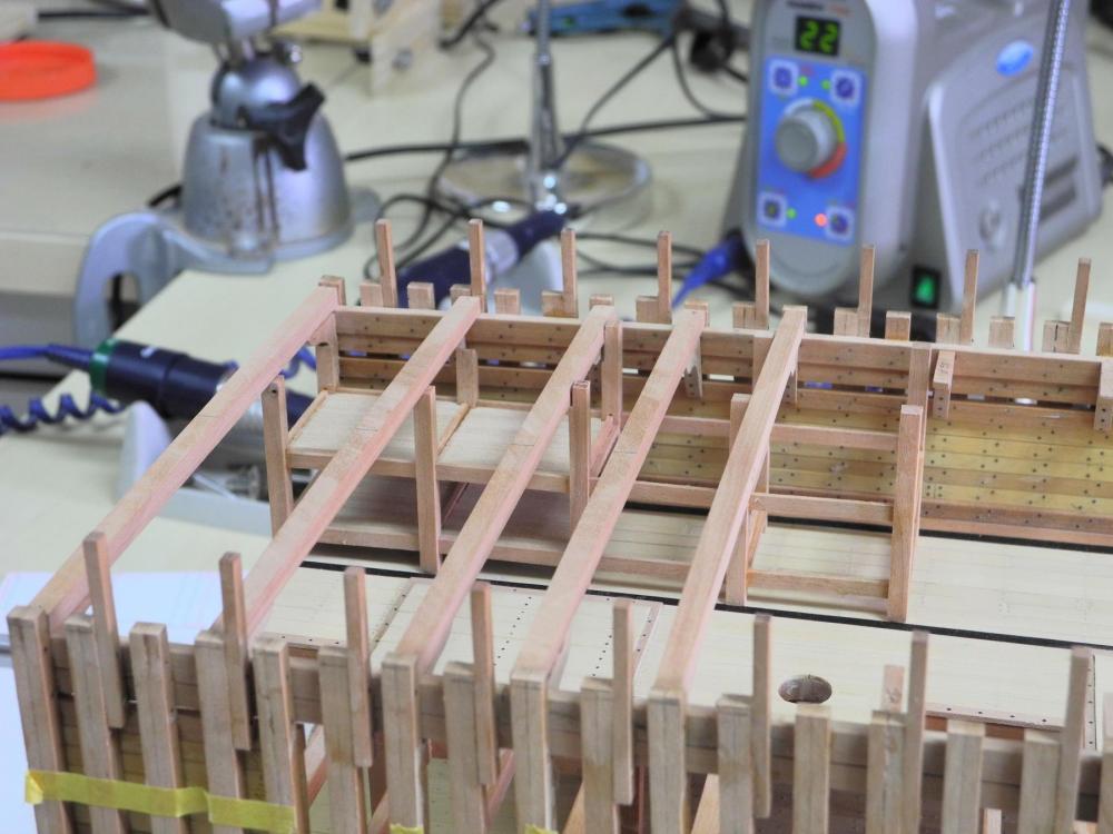
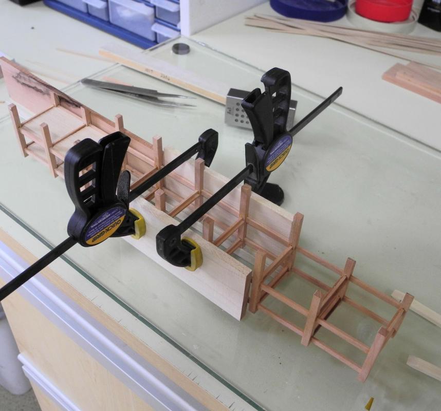
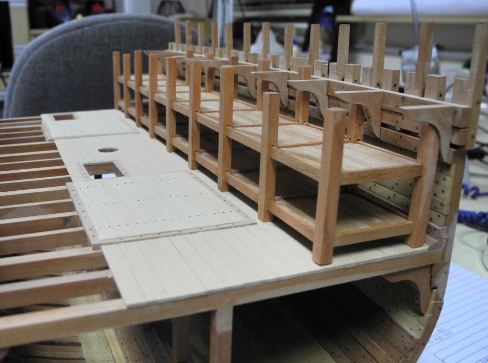
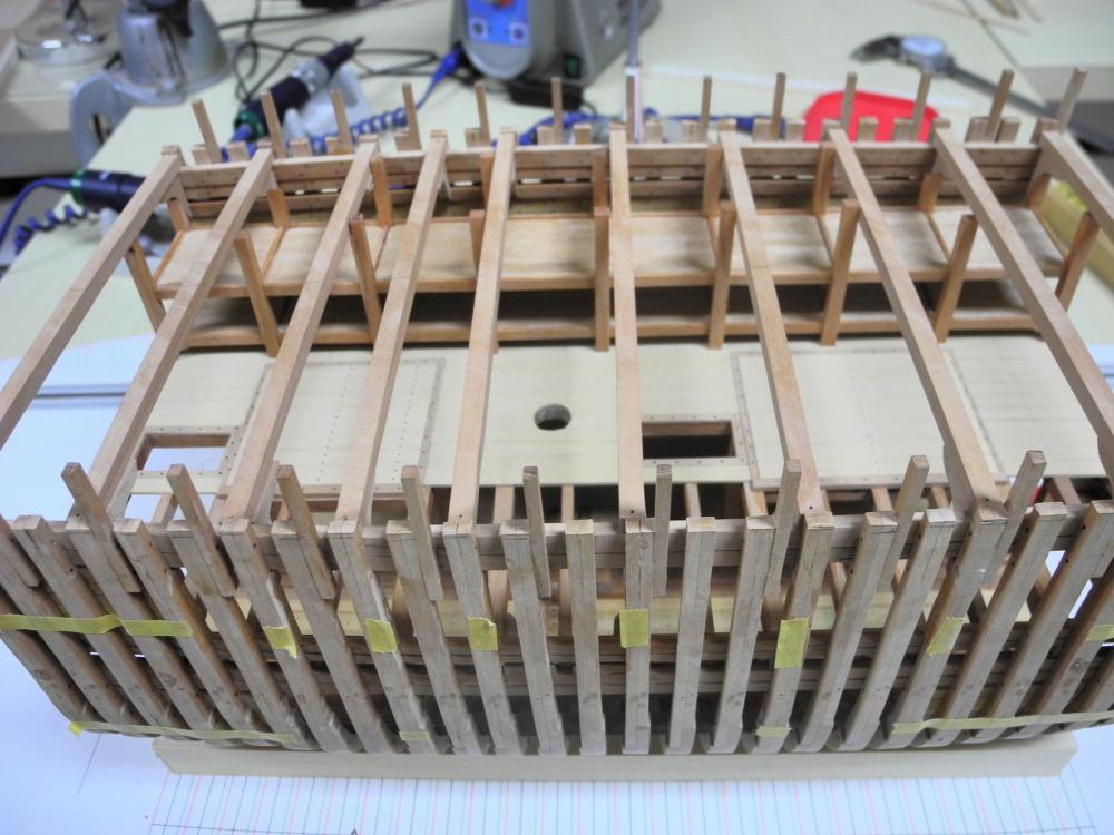
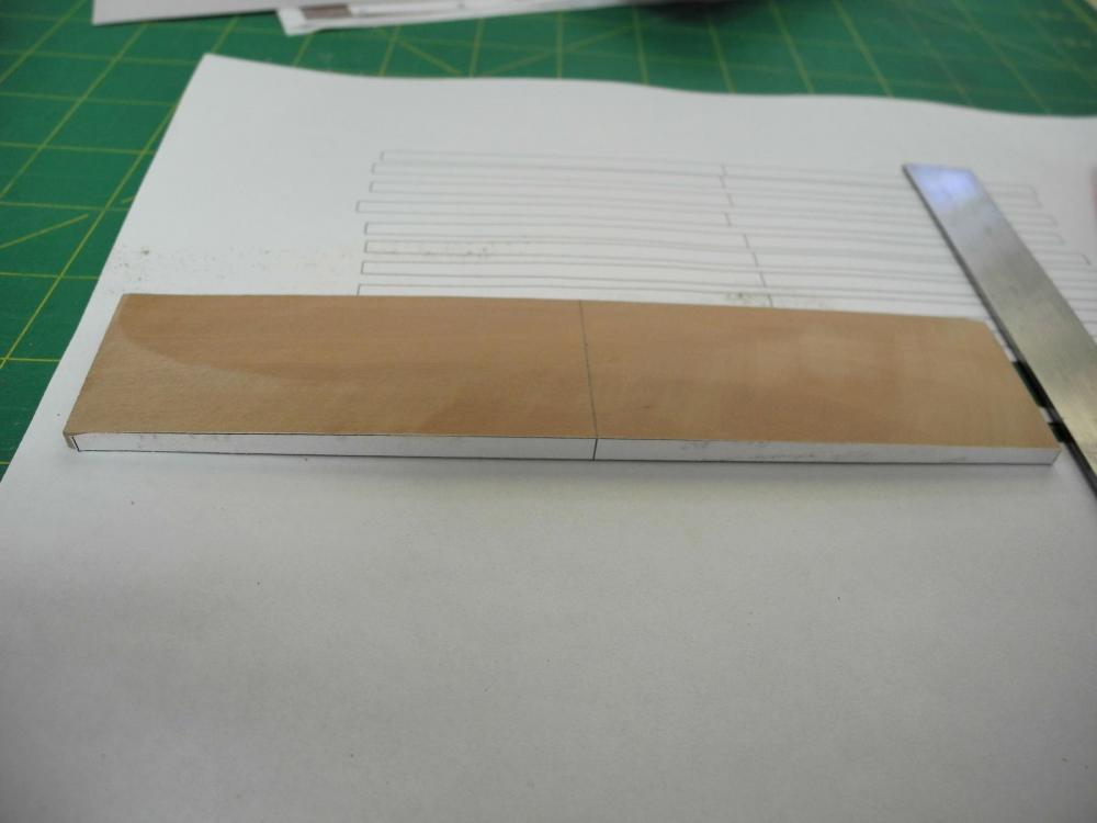
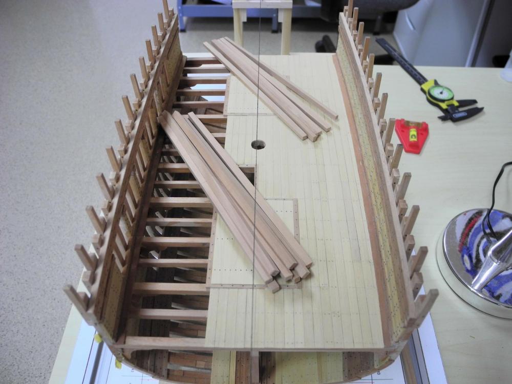
Part 33 – Sleeping Platforms for Emigrants Dunbrody has a total of 44 sleeping platforms, which provided primitive accommodations for the emigrants. These platforms were 6 ft square and were designed to each house a family of four, for a total of 176 emigrants in the allotted space. The platforms were rough-built for each trip, and I imagine they were discarded when the ship reached Canada. The sectional model has enough room for 8 of these platforms, and I decided to use different woods so that they would appear to be different from the permanent parts of the ship. I used cherry for the frames and beech for the planks that made up the floor of each platform. Building these platforms was a complex task, and I tried several different approaches until I found one that I felt I could be successful with. The side and end pieces are 3 inches thick and 8 inches high. The vertical beams are 8.25 inches square, and vary in height depending on location. The side and end pieces of the frame were mortised into the frame’s vertical beams. The end beams had mortises on two sides, while the rest of the vertical beams had mortises on 3 sides. I cut these mortises using a 1/16” end mill. Each sleeping platform needed to be square and aligned with the adjoining platforms. IThis required the use of jigs that would keep the pieces properly aligned while assembling the platforms. The jig was simple – two parallel tracks that were the correct size to snugly hold the vertical beams and were the correct distance apart. The following photo shows one of the jigs in use. I made 2 of these jigs to allow me to work on one platform when another one was being glued. I used these jigs for every mating and gluing process. Completing the first platform confirmed the approach using the jigs. I installed the horizontal planks in the first platforms I made, but then continued by focusing only on completing the frames. Placing the platforms also required some thought. Since the interior walls of the hull followed the curve of the hull, a method of aligning the sleeping platforms so that they were in a straight line was needed. I had developed a CAD drawing of the platforms in order to understand the dimensions required, and I used this drawing as a way to line up the platforms. Once the drawing was in the correct alignment crepe draftsman’s tape was used to mark the boundaries of the platforms. The tape was left in place throughout the construction. Each vertical beam needed to be checked against the height of the nearest main deck beam, and the height of the vertical beam adjusted. The main deck beams were frequently put in place to check the layout of the sleeping platforms as they were built. A majority of the sleeping platform vertical beams were either under or adjacent to a main deck beam and were adjusted accordingly. A few vertical beams are near but not touching a deck beam. In these cases a chock will be used to attach the vertical beam to a deck beam. The first platforms that were completed were the four aftmost platforms. I then worked on the forward platforms, and when three were completed the final platform was created by joining the fore and aft sets. When this was set, I installed the horizontal planks in all of the platforms, and then applied a finish to the sleeping platforms. The following photo shows the completed sleeping platforms. There is still some minor adjustment needed for the placement of the platforms. The following photos show the platforms temporarily installed. From my perspective, completing the sleeping platforms is a major milestone. These platforms are probably the one thing that influenced my decision to build the Dunbrody. It’s hard to imagine sick and starving people living in these conditions during a transatlantic voyage. Thanks everyone for following this build, and for all of your comments, encouragement, and ‘likes’.


- 649 replies
-
- 27
-
-
- dunbrody
- famine ship
- (and 2 more)
-
Ed - glad to see another Young America update. Even on a small task you demonstrate a level of precision I'd love to be able to achieve.
- 3,618 replies
-
- 3
-
-
- young america
- clipper
- (and 1 more)
-
Thanks Ed. Hope your work on the book is progressing well.
- 649 replies
-
- 4
-
-
- dunbrody
- famine ship
- (and 2 more)
-
Thanks again Brian - our little chat helped me think through a lot of things about the work still to come. Thanks Bob. One of these days I'll get up there to see you again - probably in August, since we have a few weeks of vacation coming up. Thanks Toni. It's nice to have a few modelers here in the desert - we get together every so often.
- 649 replies
-
- 3
-
-
- dunbrody
- famine ship
- (and 2 more)
-
Very nice Patrick! The amount of detail in such a small space continues to amaze me.
-
Thanks Druxey. The key was Brian's suggestion about installing the knees first.
- 649 replies
-
- 4
-
-
- dunbrody
- famine ship
- (and 2 more)
-
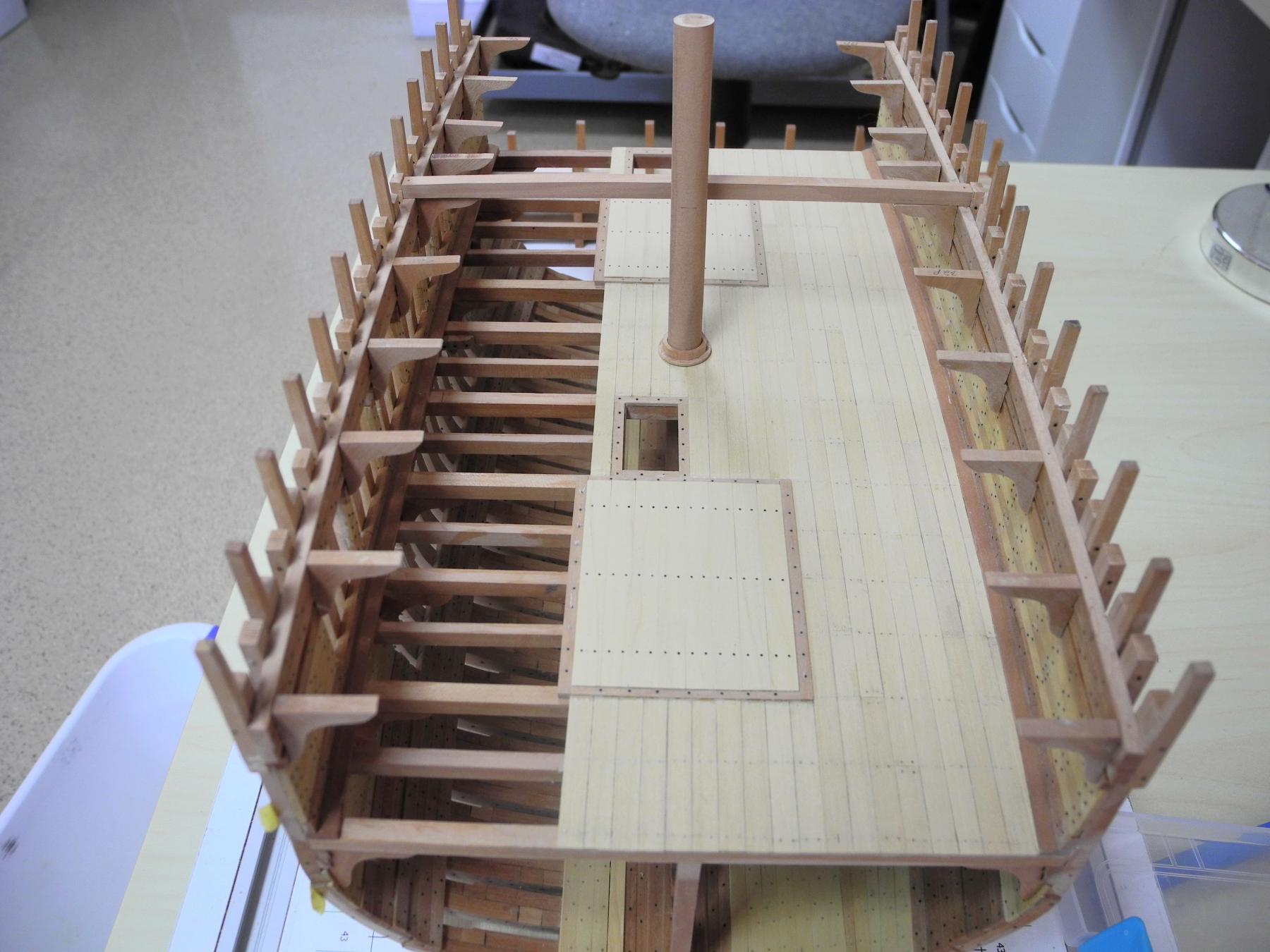
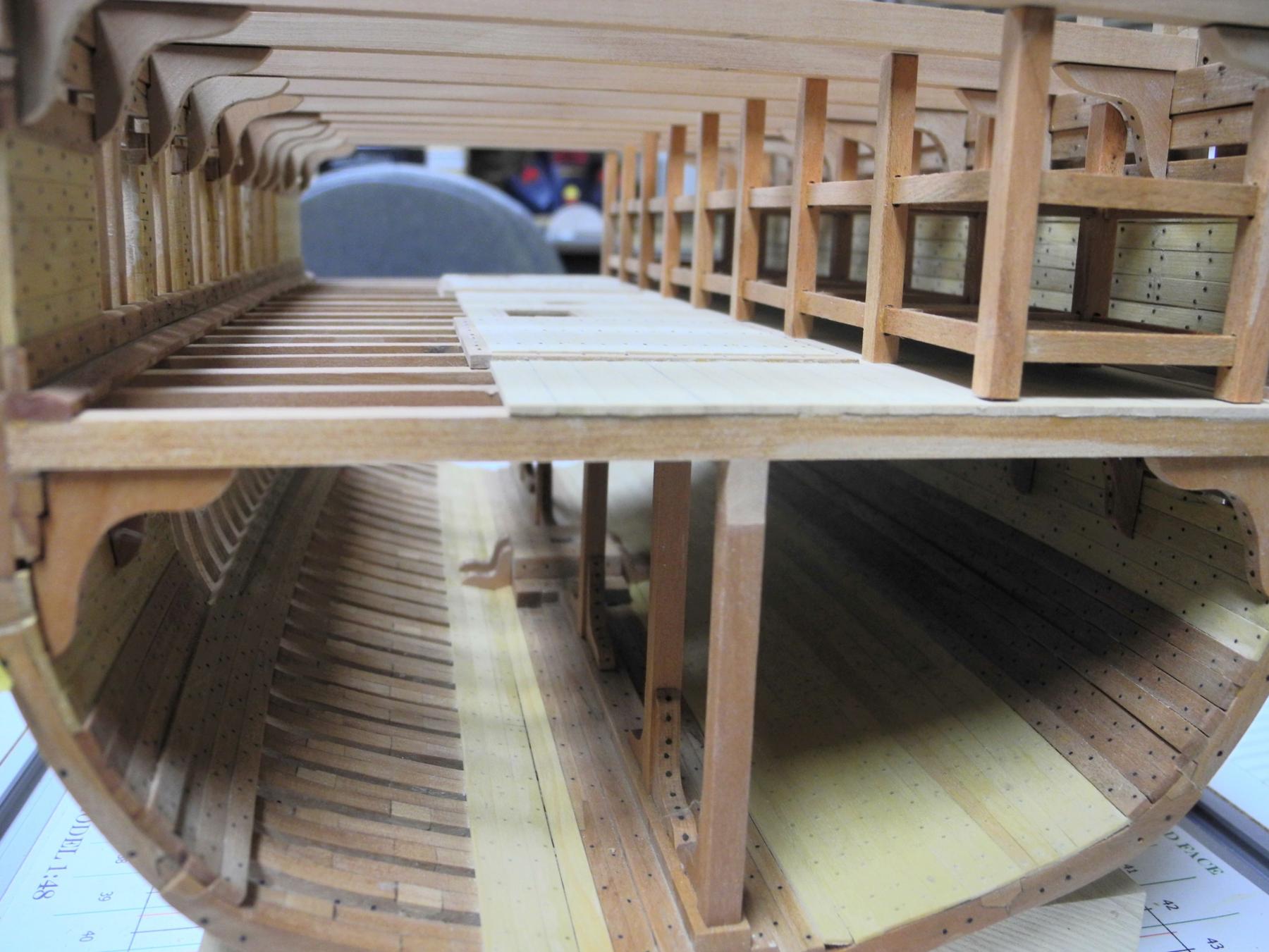
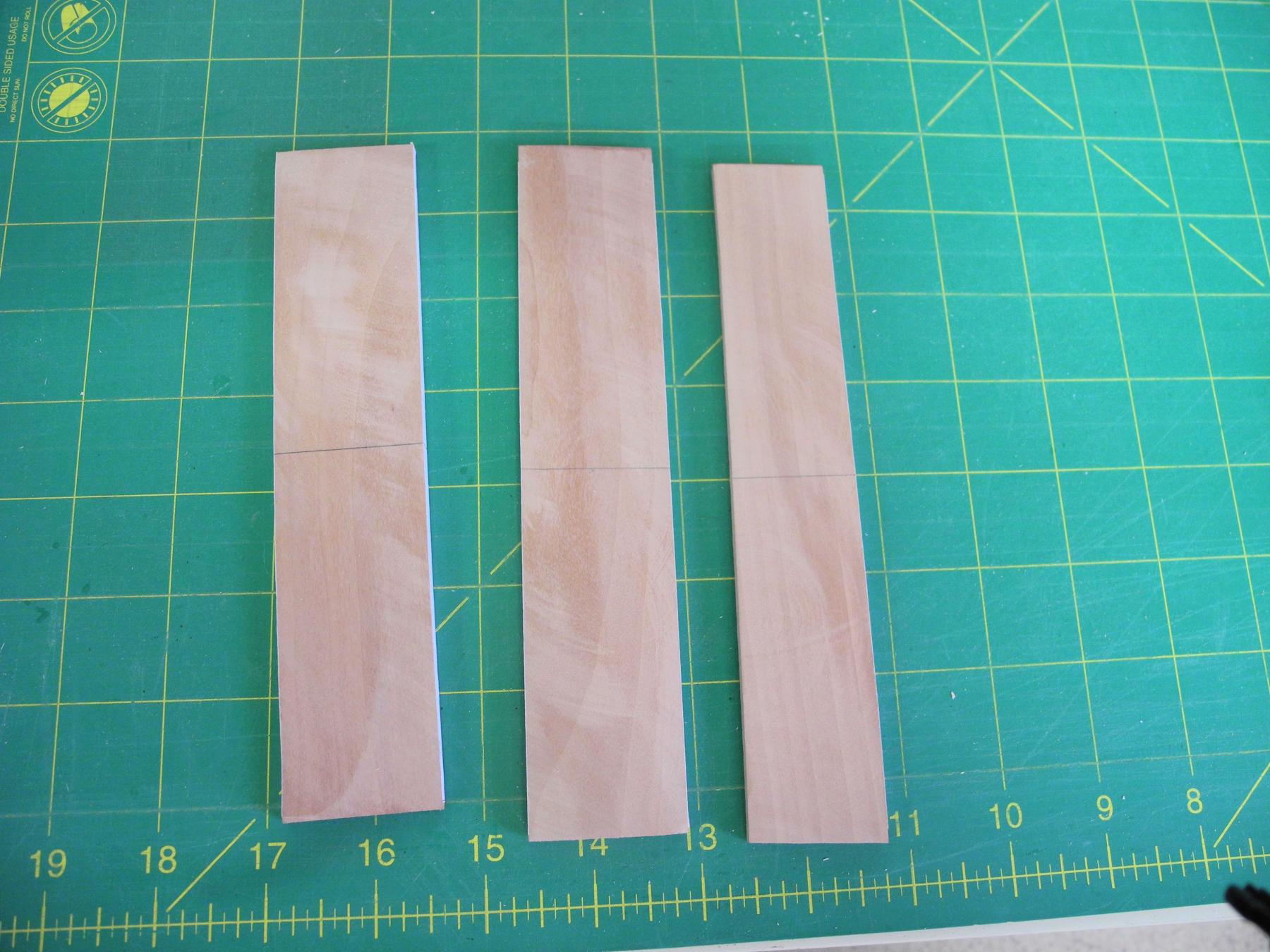
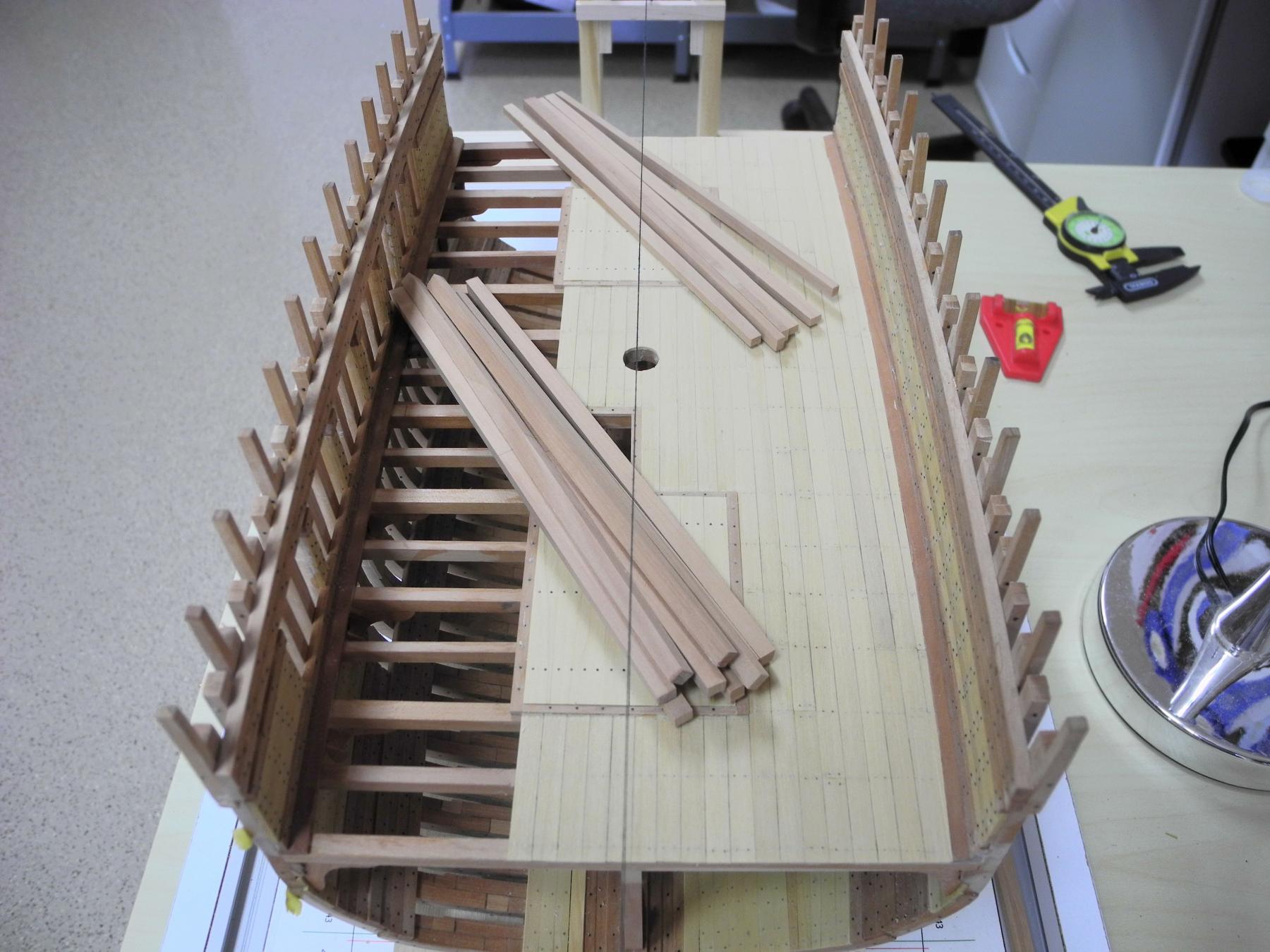
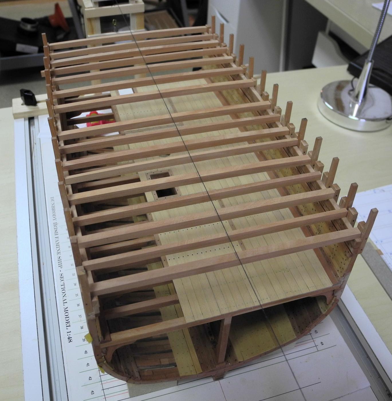
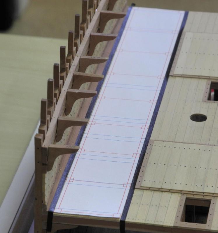
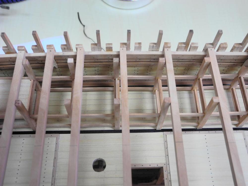
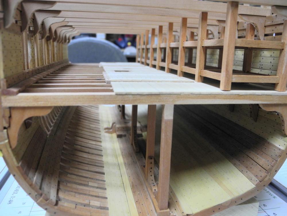
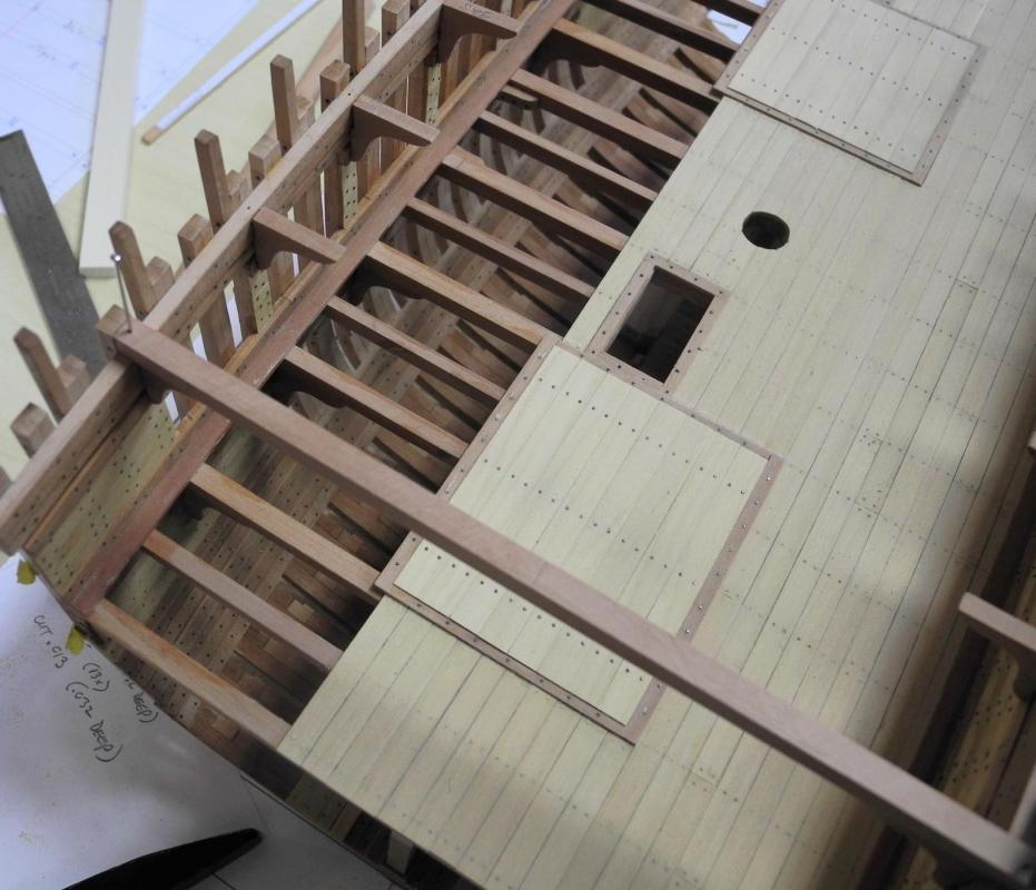
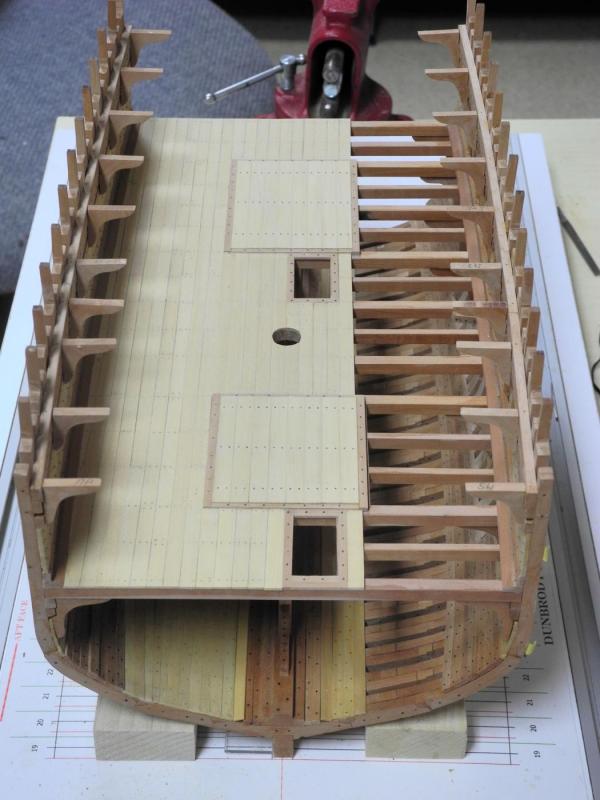
Part 32 – Main Deck Beams and Hanging Knees The Accommodation Deck still has a lot of details to be added: Sleeping Platforms, Bucket Lavatories, Tables and Benches, Companionways (ladders) to the hold, and safety railings around the companionways. In addition to the Accommodation Deck details, the main deck beams and associated hanging knees and lodging knees have to be added. This mix of work to be done leads to the question of what to install first: If the Accommodation Deck details are constructed first, there will be very little room to work on the hanging knees. If the main deck beams and hanging knees are constructed first, then it will be very difficult to install the Accommodation Deck details without risk of damaging knees or beams, or both. In a discussion with Brian (GuntherMT), he suggested that an alternative would be to install the hanging knees without permanently installing the beams, then work on the Accommodation Deck details, and then install the beams when all is completed. This made sense to me, so it’s the approach I’ll be using for fitting out all of the Accommodation Deck details. (Thanks, Brian!) The Main Deck Beams have a slight camber on top but are flat on the bottom. To construct the beams, lumber was milled to be slightly thicker than the moulded dimension of the crown of the deck. I then glued a CAD-produced profile of the deck beam on the front and back of the billet I had produced. The camber for the top of the beams was then shaped by sanding the billet on the disk sander. Since the drawn profile of the deck beam also included a vertical line indicating where the crown of the deck is, this line was used to draw a centerline across the billet. When the beams are parted off, each beam will then have its own centerline already drawn. The required number of main beams and second beams were parted off, leaving the width of each beam slightly larger than needed. The beams were then run through the thickness sander until they were the required thickness. Some of the beams will actually be partial beams – for example at the sides of the main hatch. These beams were cut as full length beams until they are used, and then the correct part of the beam will be used for the partial beam so that the correct camber will be maintained. The beams were then dry-fit in place and marked to indicate which frame position the beam was for, and which side was port vs starboard. Making the hanging knees followed the same process previously described for the hanging knees of the Accommodation Deck Beams. The appropriate Main Deck Beam was temporarily pinned in place to allow fitting of the hanging knees for that beam. The 10 pairs of hanging knees are now installed, and the rest of the Accommodation Deck details can now be worked on. That will be the subject of the next few posts.


- 649 replies
-
- 23
-
-
- dunbrody
- famine ship
- (and 2 more)
-
I like the shot of the model in front of the iPad-based photo - it shows just how great your work turned out. BRAVO!!
-
Thanks Mark. I haven't applied a finish to the deck yet. I expect that when I do the treenails will be more visible, and I hope that still looks ok. Thank you Albert. Dream on, Patrick. There are too many other projects I want to start, so Dunbrody will remain a mid-section. Glad you're enjoying the log. Thanks Druxey. I got those weights from a jeweler friend when he closed his shop, and I've been looking for something to use them for.
- 649 replies
-
- 5
-
-
- dunbrody
- famine ship
- (and 2 more)