HOLIDAY DONATION DRIVE - SUPPORT MSW - DO YOUR PART TO KEEP THIS GREAT FORUM GOING! (Only 36 donations so far out of 49,000 members - C'mon guys!)
×


Mahuna
-
Posts
1,504 -
Joined
-
Last visited
Content Type
Profiles
Forums
Gallery
Events
Everything posted by Mahuna
-
 Beautiful, Ed! Your brass work could pass for jewelry. I agree, it's a shame it has to be blackened.
- 3,618 replies
-
- 7
-

-
- young america
- clipper
- (and 1 more)
-
LOL!! Yesterday I started labelling every sister keelson in light pencil with the side (P or S) and end (F or A) since they all looked the same and I wanted the scarfs in particular places. Seems like something I'll continue doing.
- 649 replies
-
- 7
-
-
- dunbrody
- famine ship
- (and 2 more)
-
Thanks everyone for the encouragement, ideas, and 'forgiveness'. I'm going to try to disguise the scarf under the mast step. This has been another valuable lesson about planning and double-checking. I'm learning something new every day that I work on Dunbrody, whether it's about ship construction, processes, or techniques. Overall, a very enjoyable and challenging experience, even with the boo-boos!
- 649 replies
-
- 11
-
-
- dunbrody
- famine ship
- (and 2 more)
-
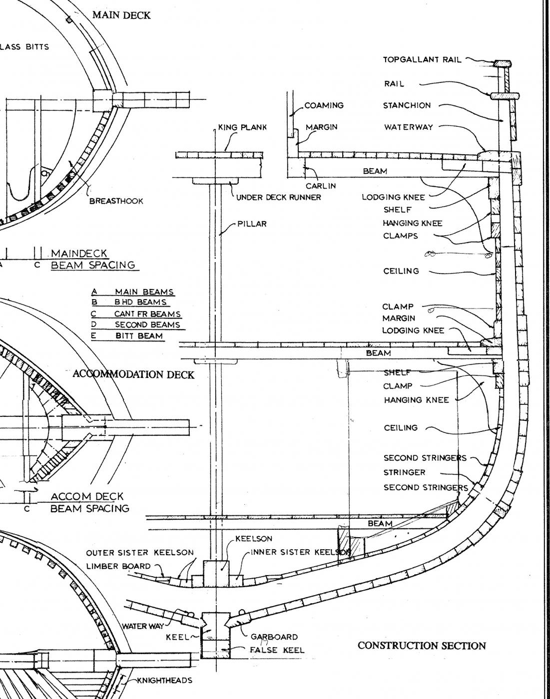
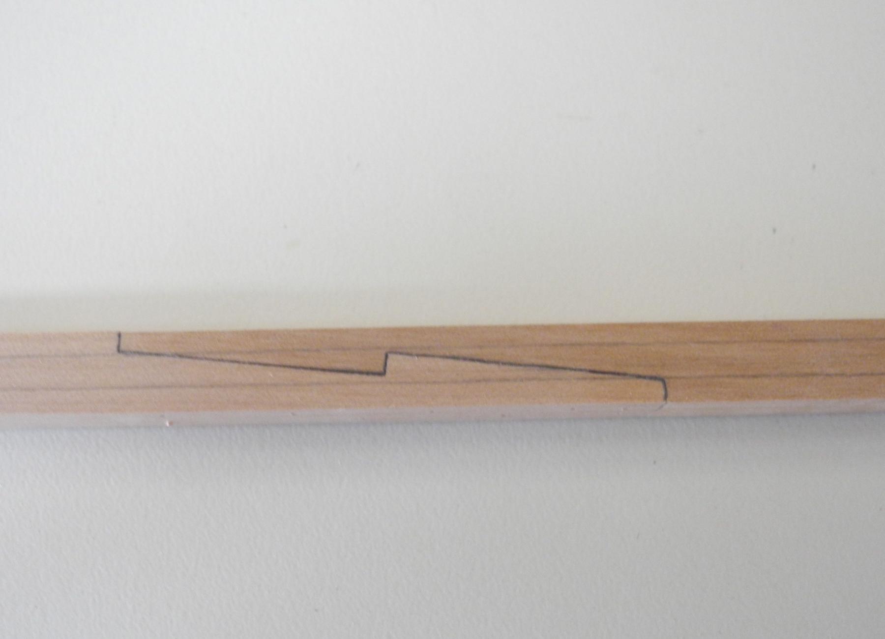
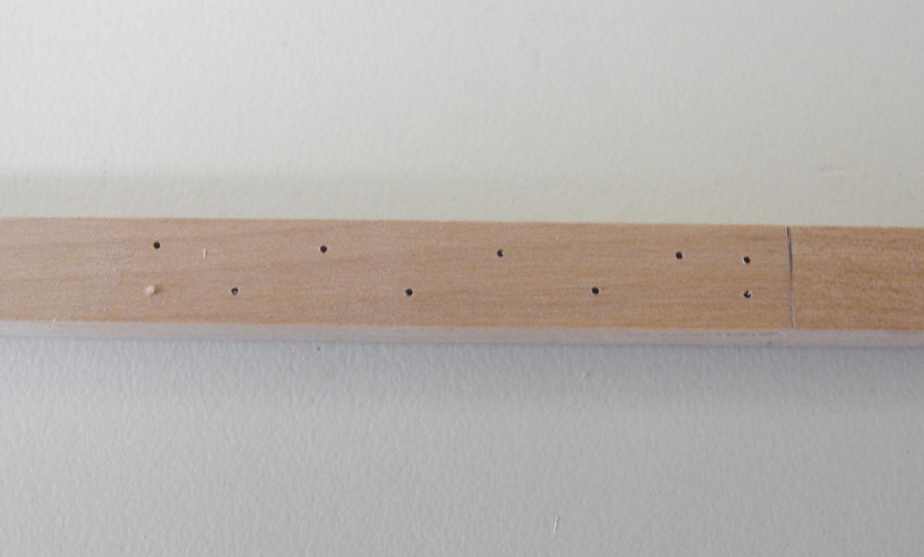
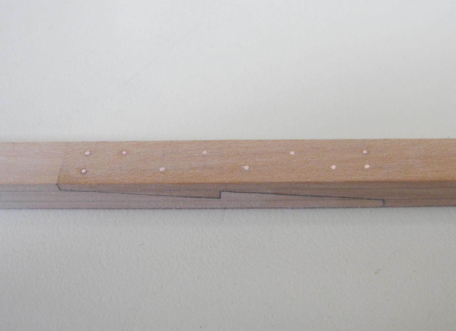
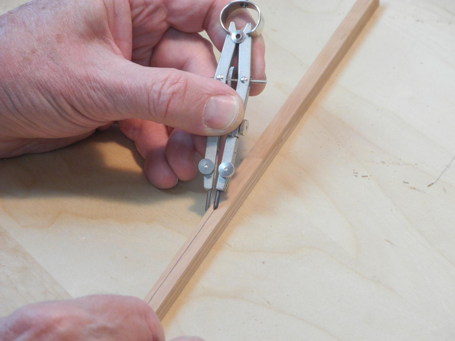
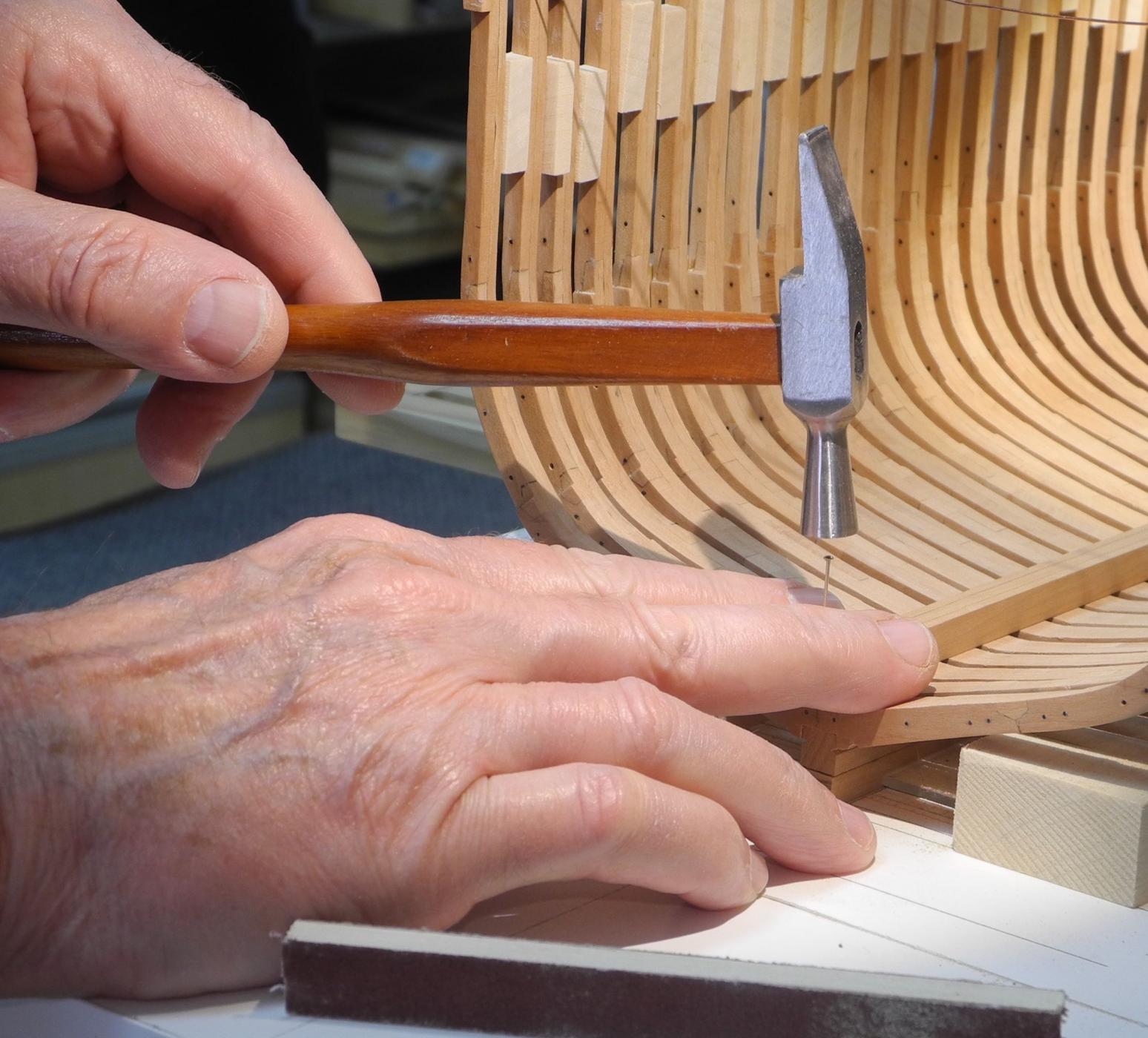
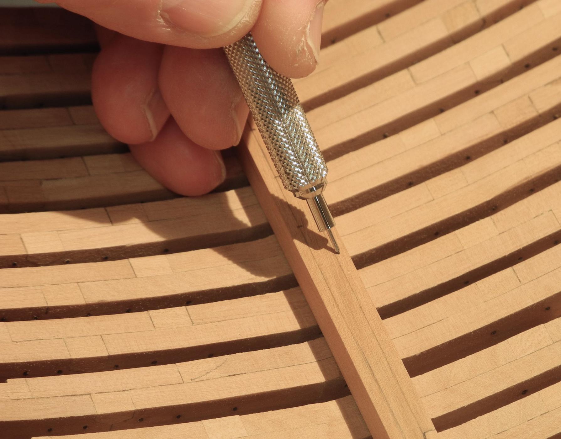
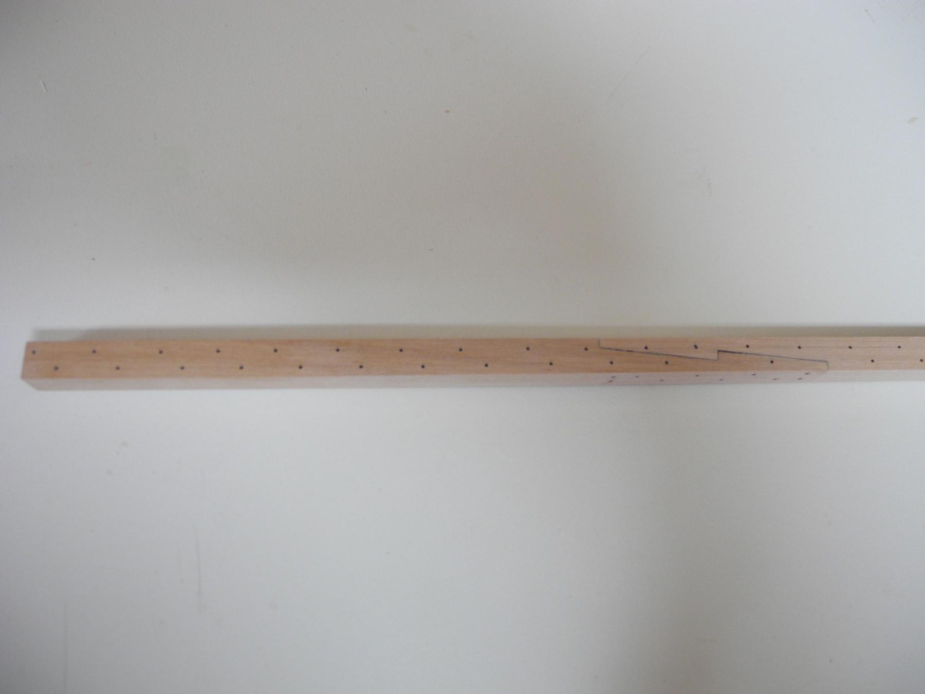
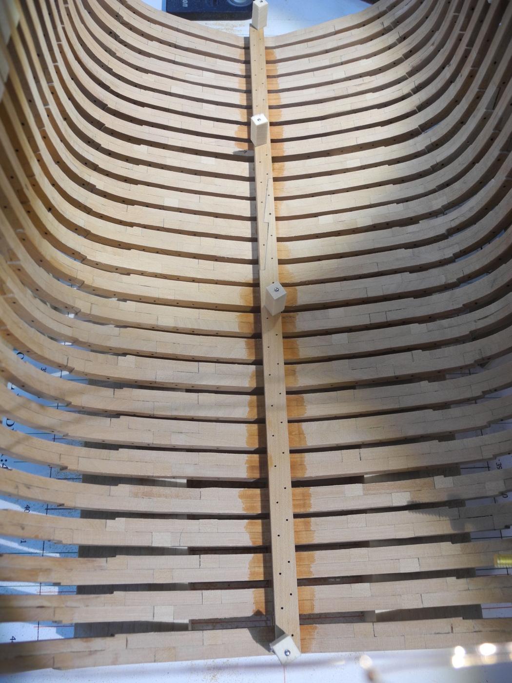
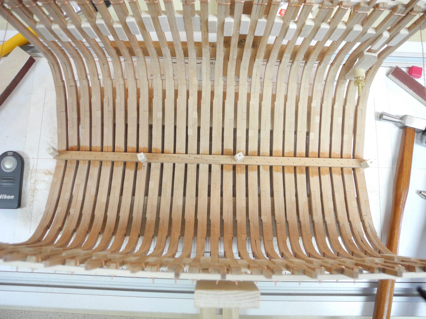
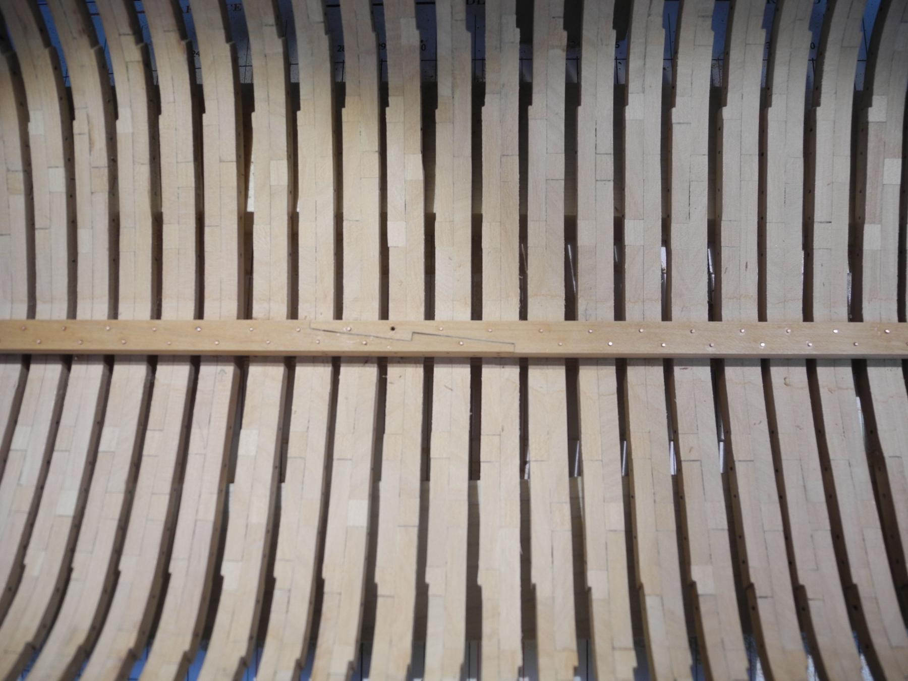
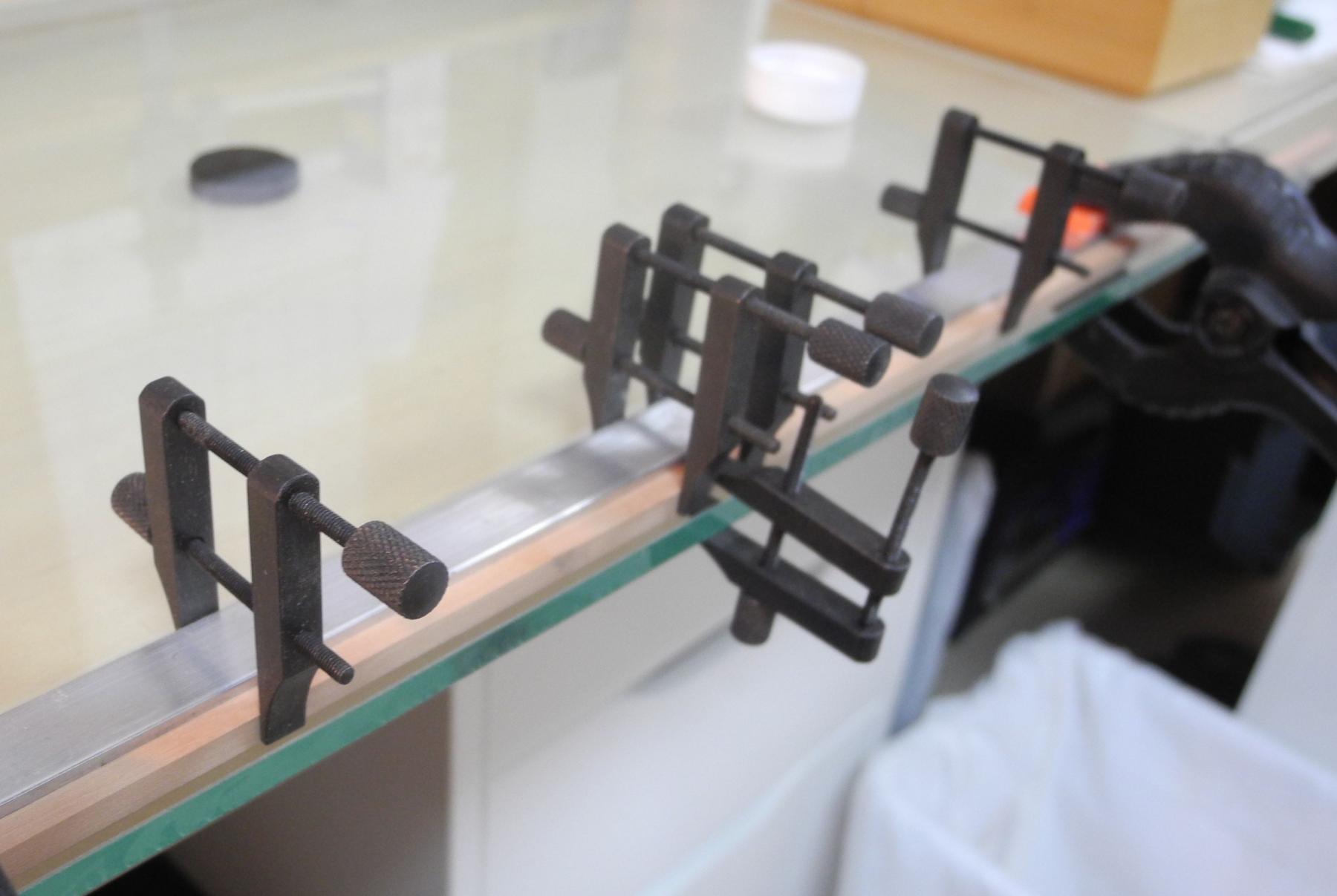
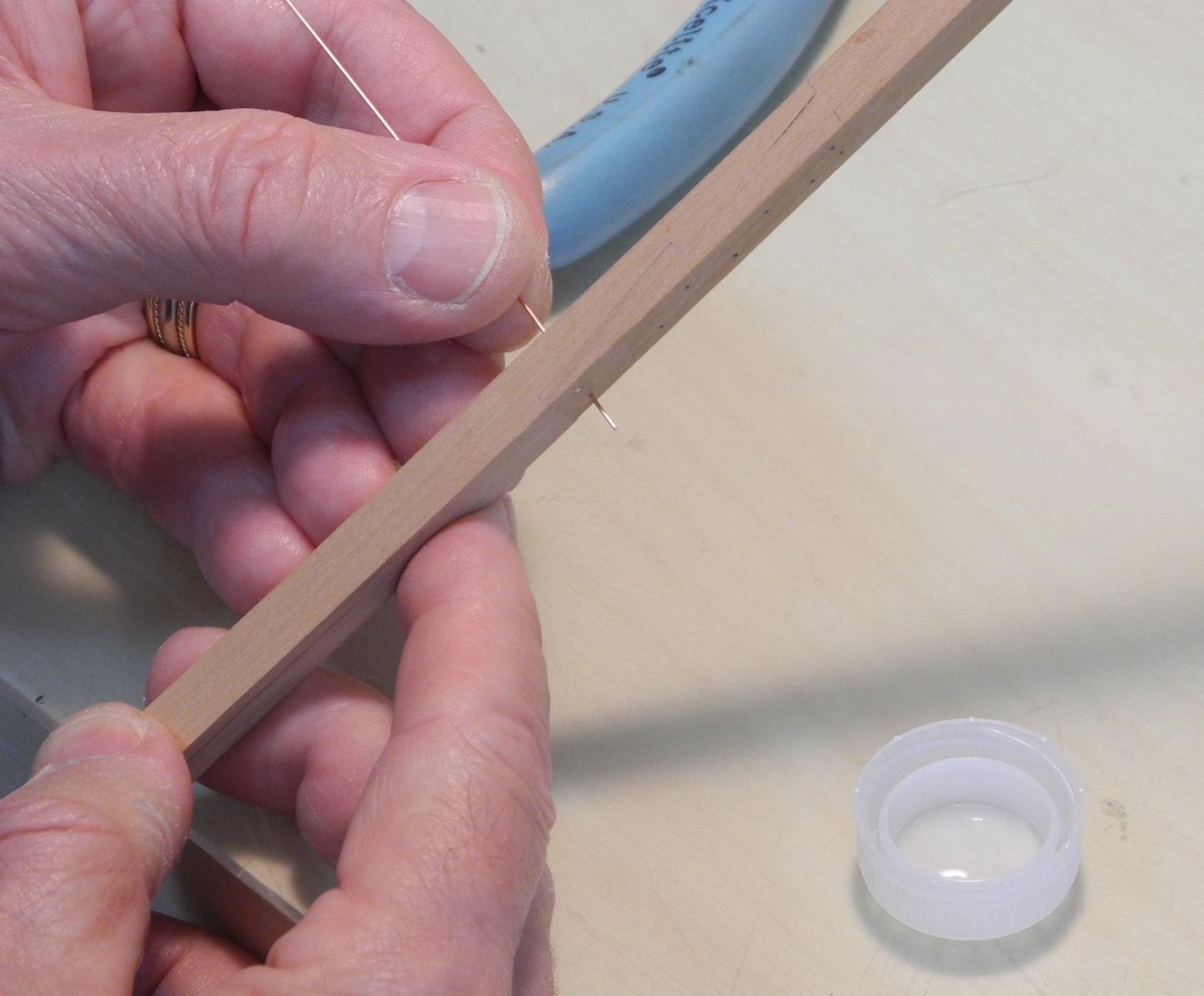
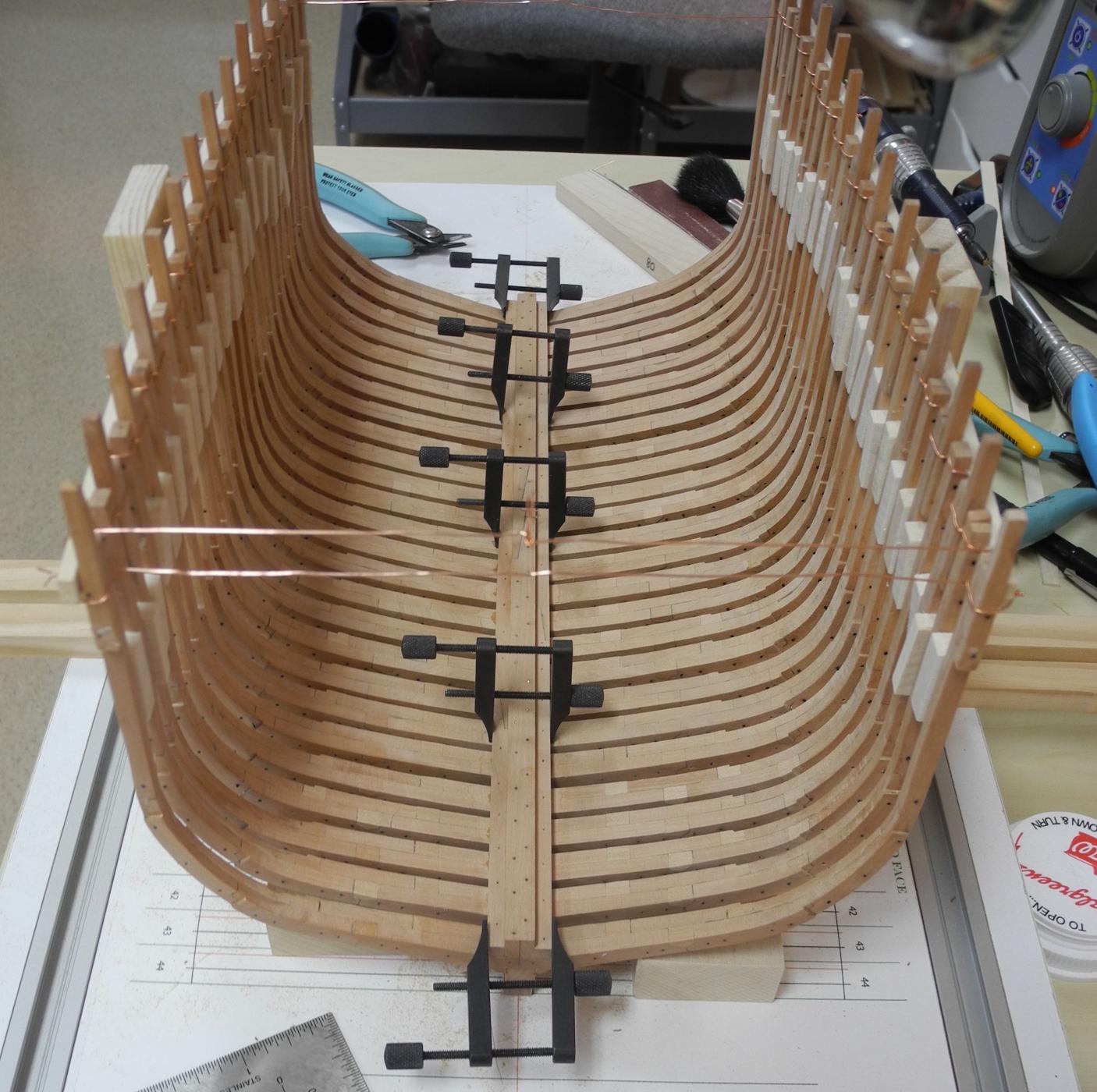
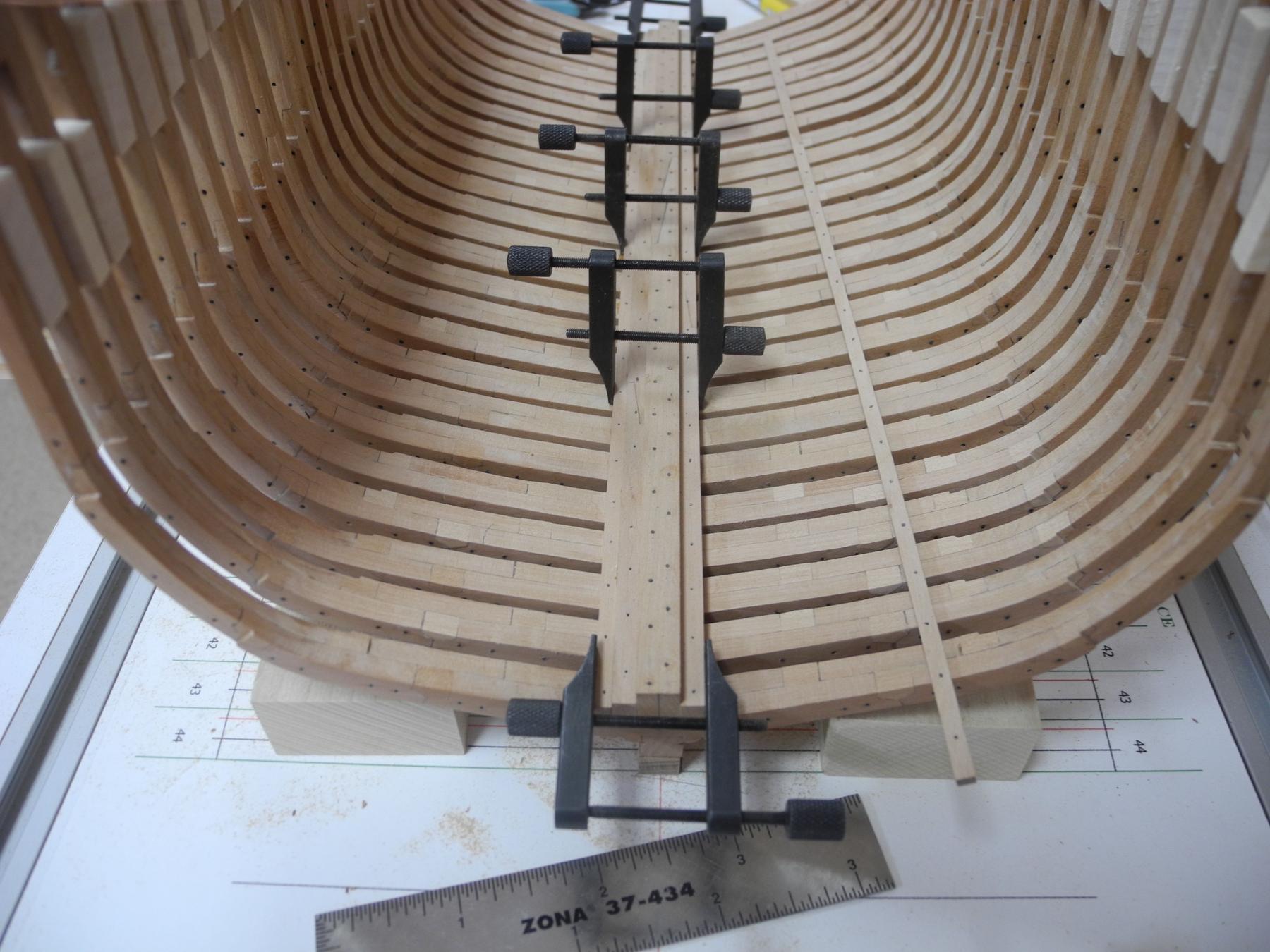
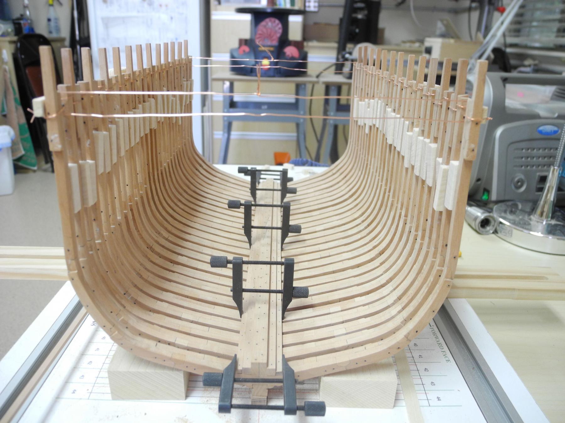
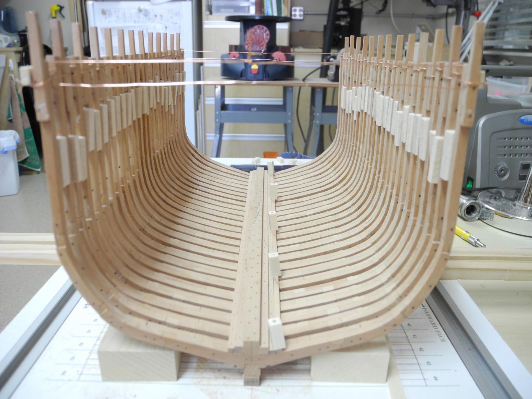
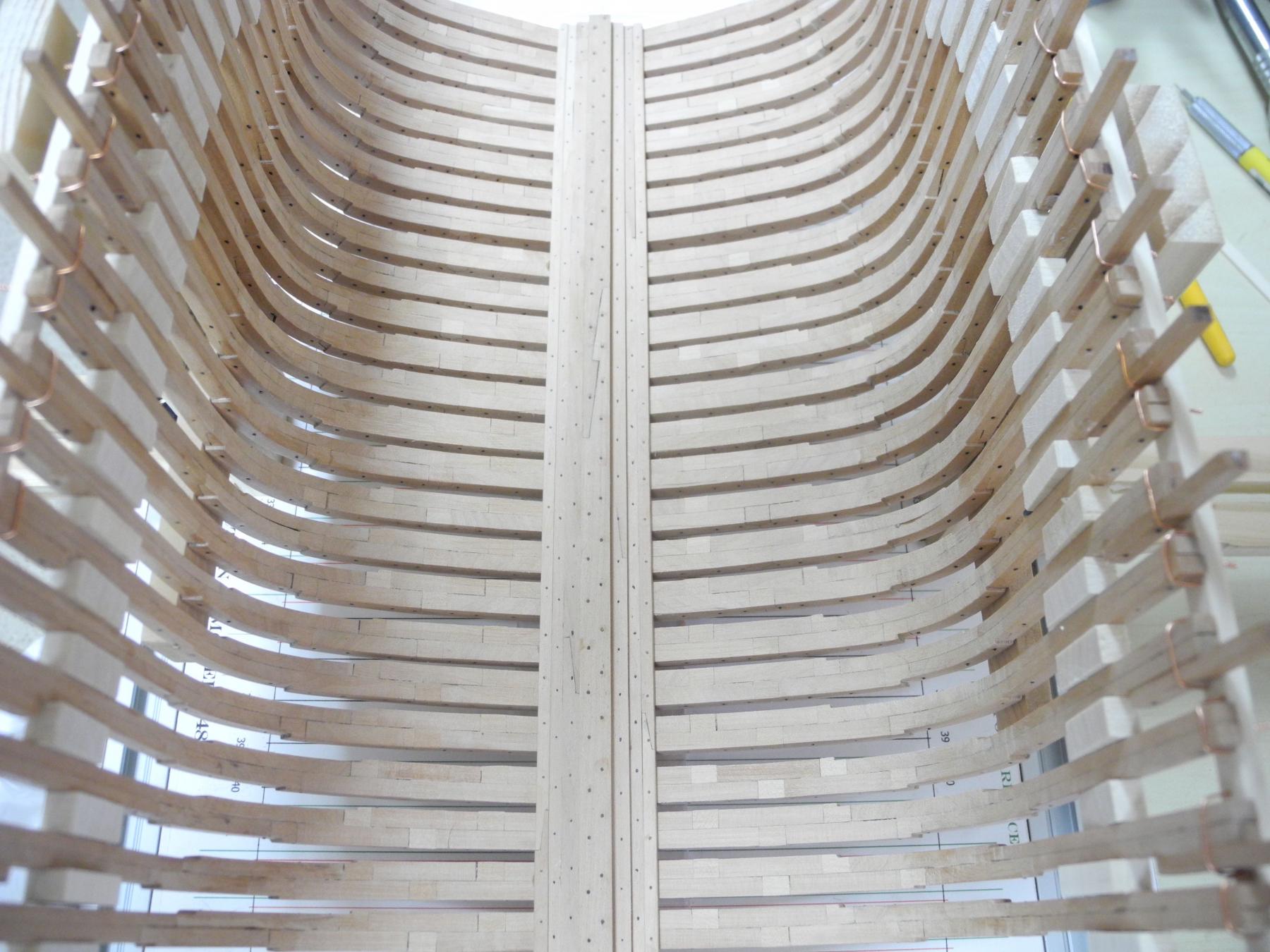
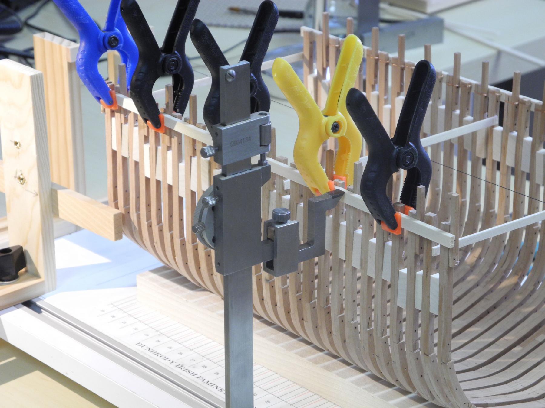
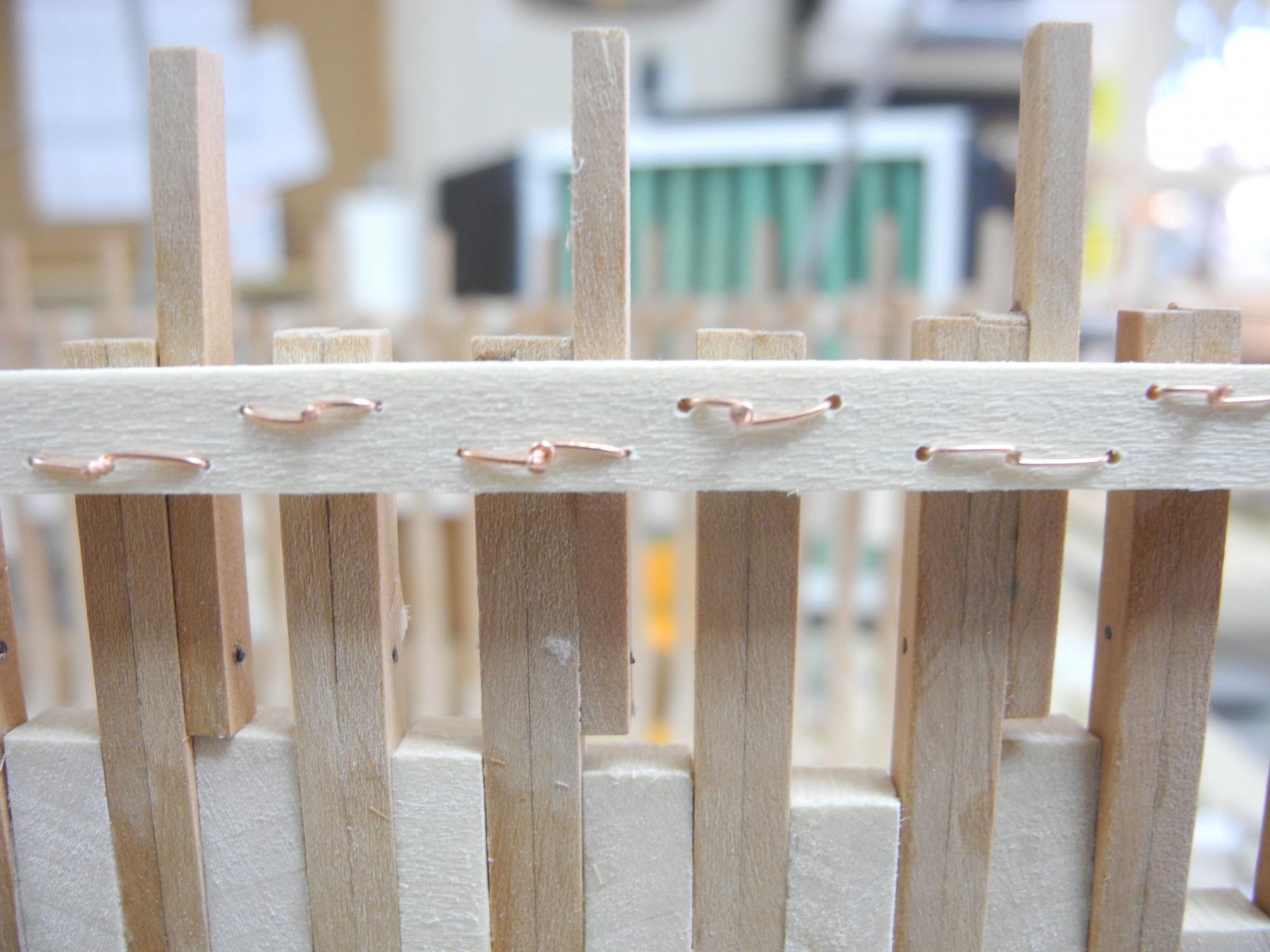
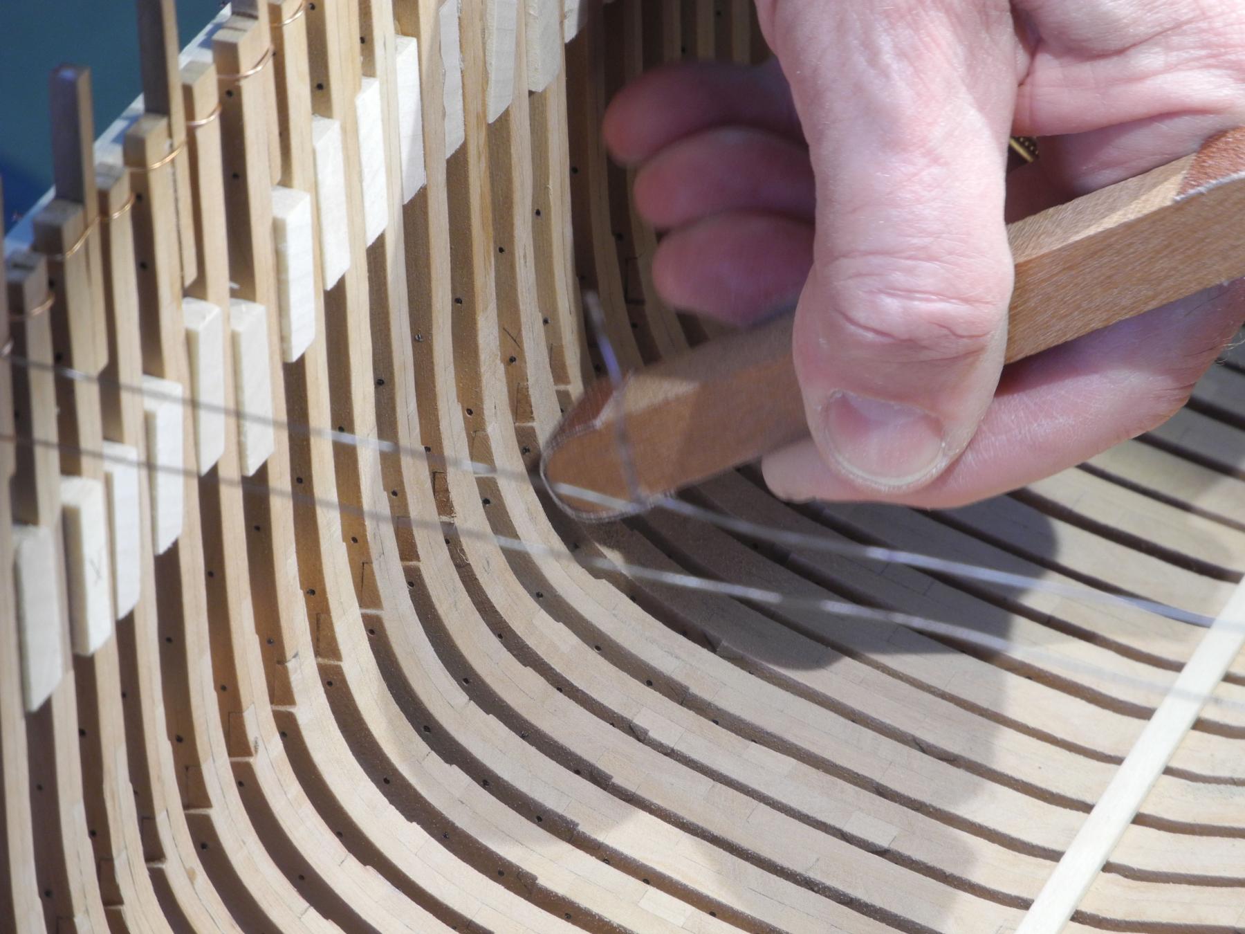
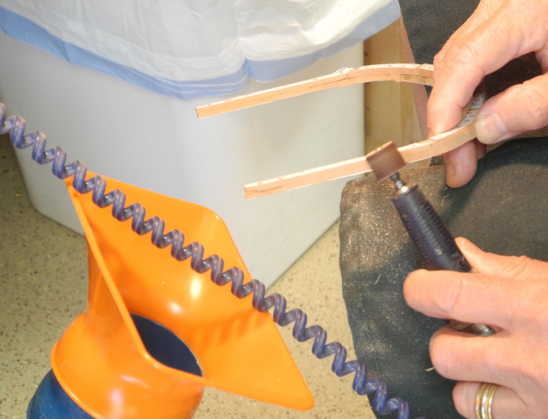
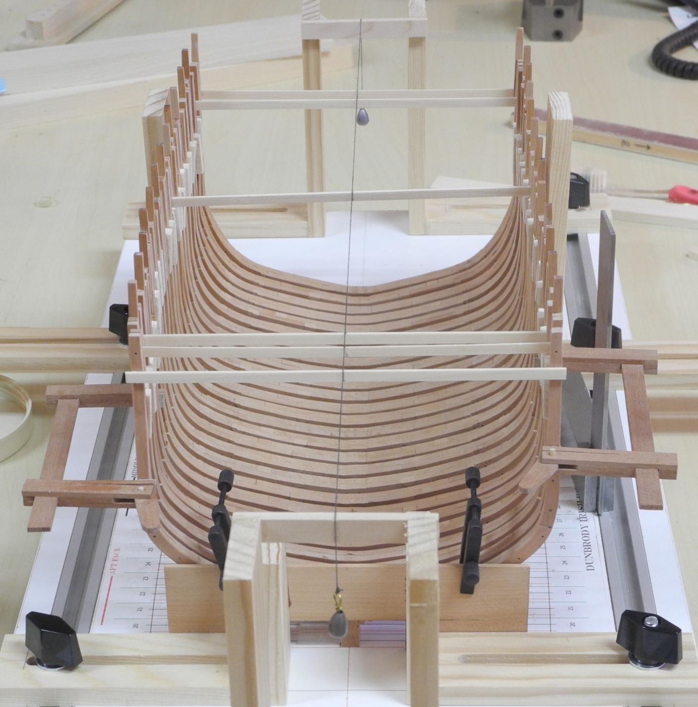
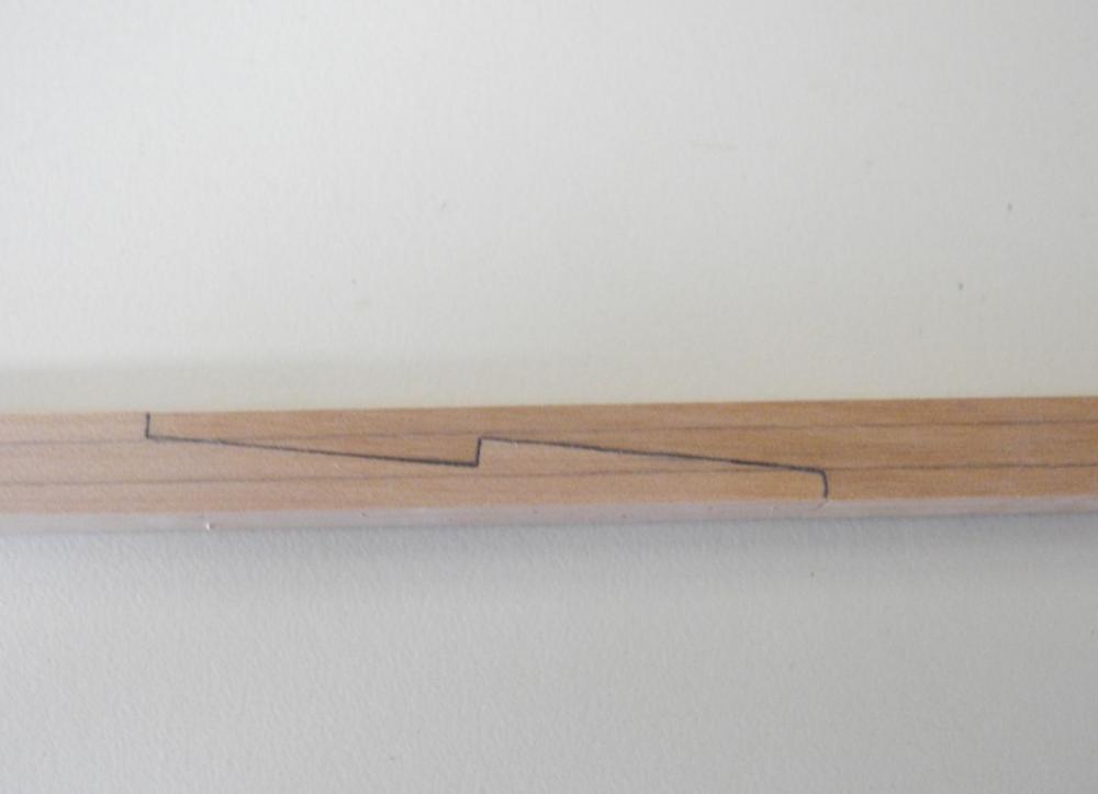
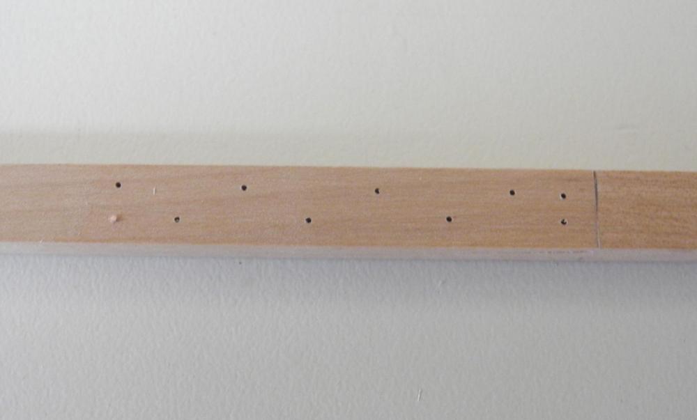
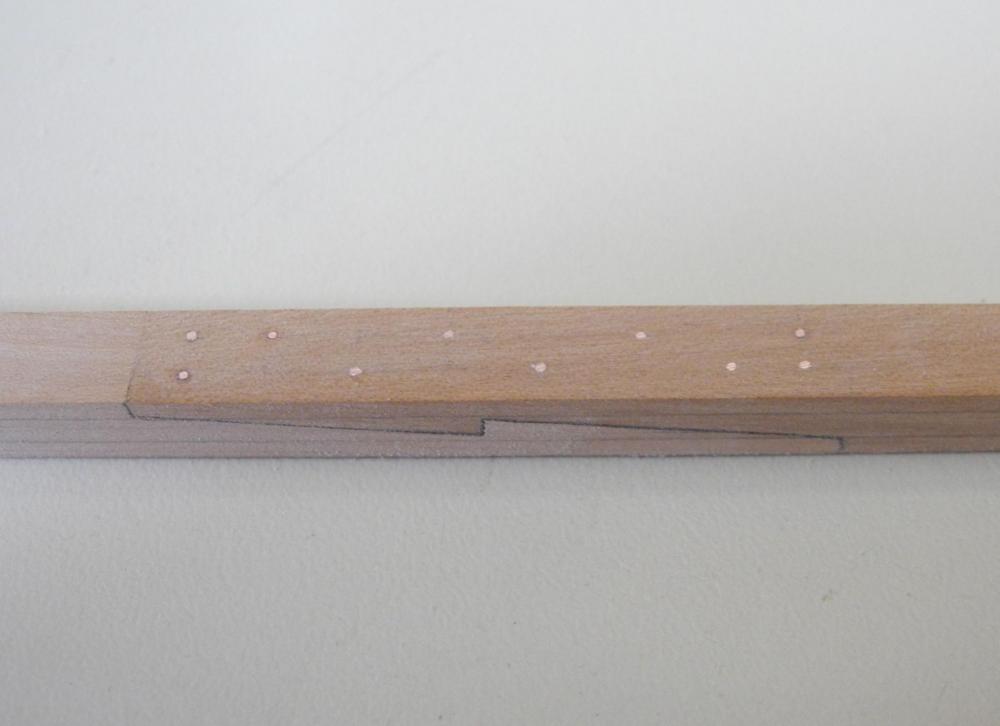
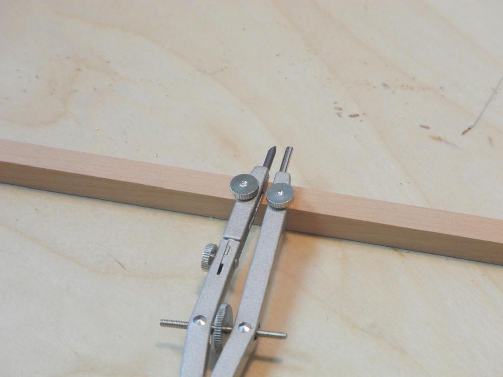
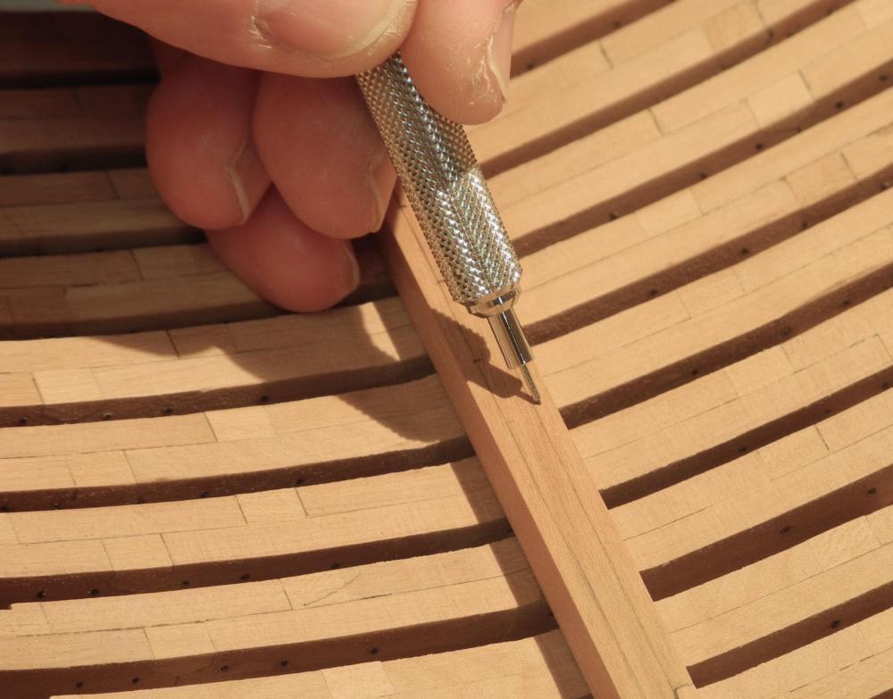
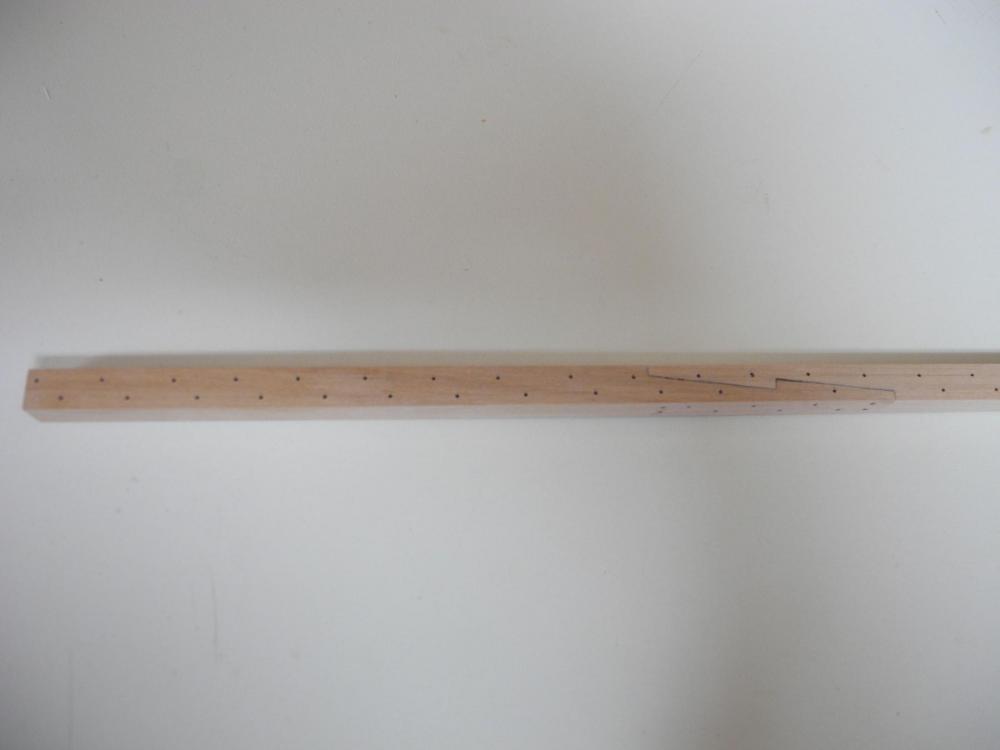
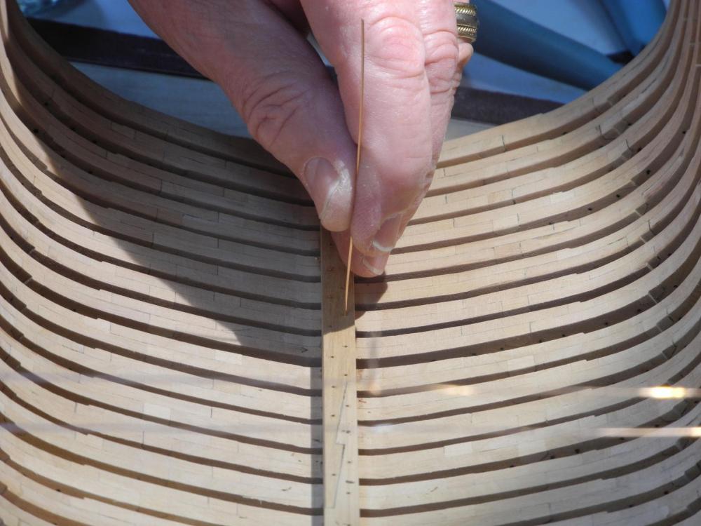
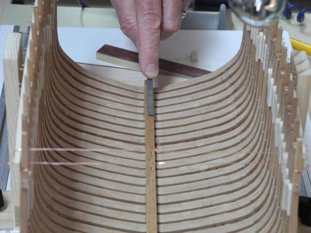
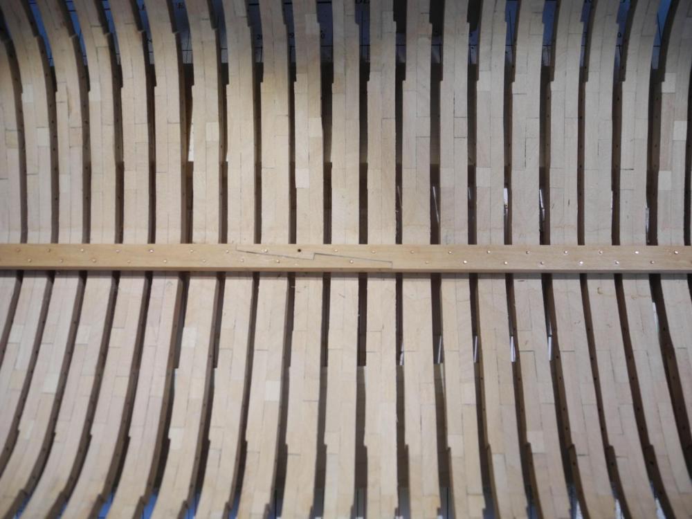
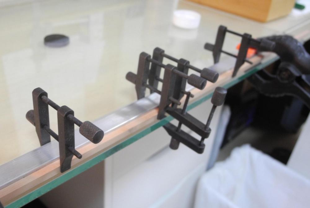
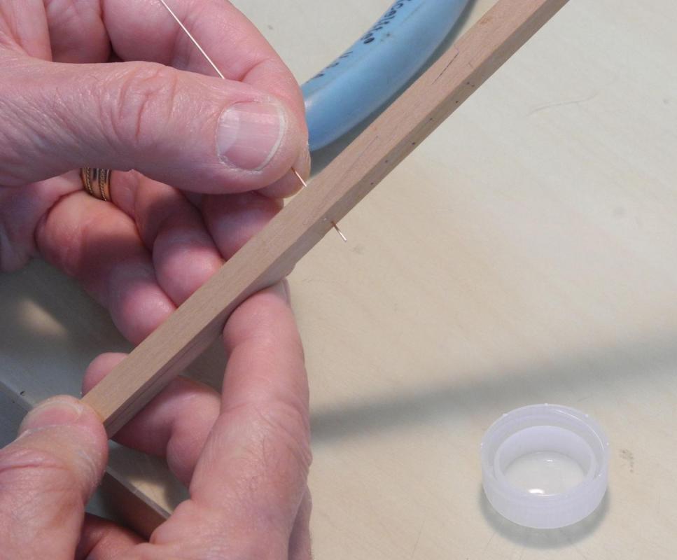
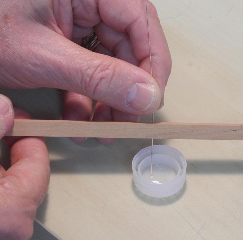
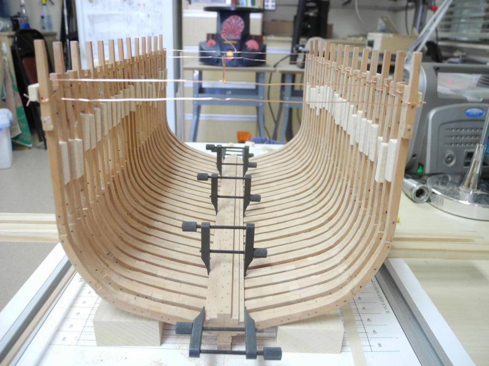
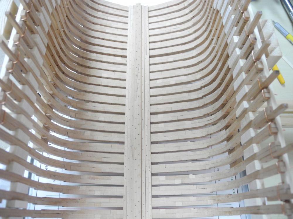
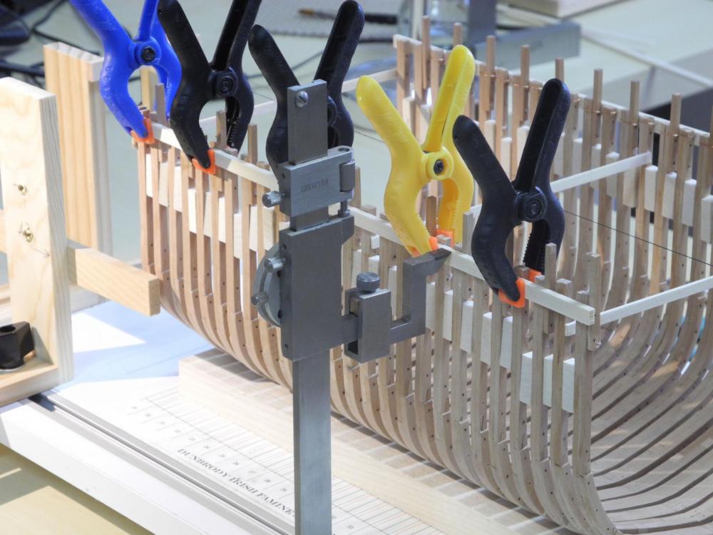
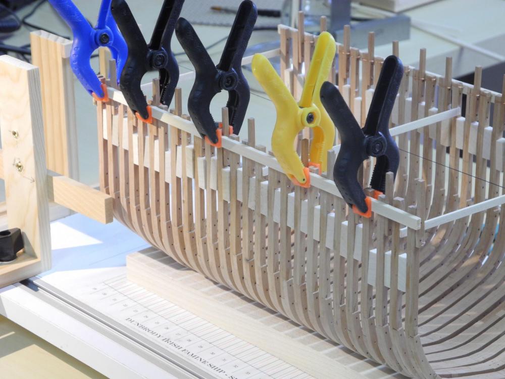
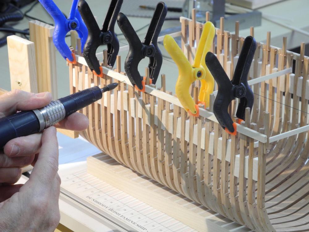
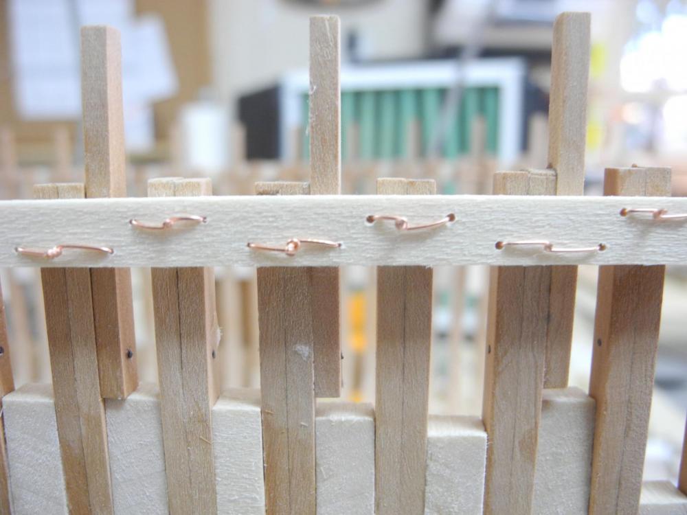
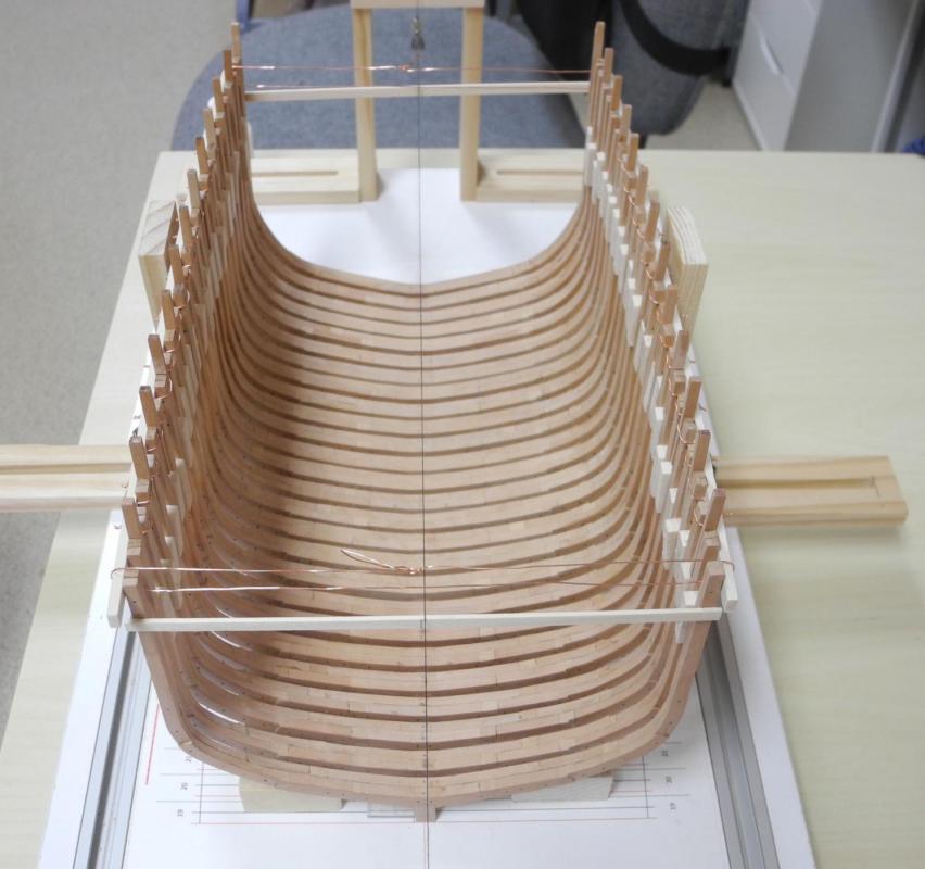
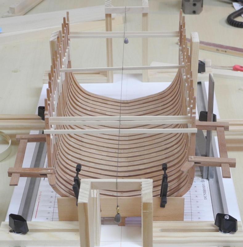
Part 17 – The Keelsons Dunbrody has a single Keelson, and numerous Sister Keelsons. The central Keelson measures 14” x 14”. I rounded all scale measurements to the nearest 64th for accurate milling, so the Keelson scale size is 9/32 x 9/32. The sister Keelsons are arranged as two Inner Sister Keelsons, installed on each side adjacent to the Keelson, with two additional Outer Sister Keelsons on each side. On the hull cross-section in the plans, the Inner Sister Keelsons measure 6” square. This seemed too small, so I increased it to 8” square (11/64 square on the model). Next to the Inner Sister Keelsons are two smaller Sister Keelsons on each side, called the Outer Sister Keelsons (Crothers would call these the ‘Cousin Keelsons’, but what’s in a name?). These Outer Sister Keelsons are 6” x 8”, or 3/32 x1/8 on the model. The following is the cross-section from the plans. Since the length of the all of the Keelsons on the sectional model would be 48 feet, and since available timbers generally were less than 40 feet, each member of the keelsons would require a scarf joint. The scarf for the main Keelson is a horizontal hooked scarf. This scarf joint would be bolted for extra strength, using 1.5” bolts, so a series of bolt holes was drilled. I used 22 gauge copper wire, unhardened but pulled straight. After these bolts were installed in the scarf joint they were filed flush using a riffler, and then were blackened using Liver of Sulphur. In addition to glueing to attach the Keelson to the frame floors, I decided to use functional bolts for additional strength. Since these bolts would be visible on the model they needed to be properly arranged. I used a compass to draw lines parallel to the sides of the Keelson. The small metal piece was reversed so that the flat side, rather than the tapered end, rode on the side of the Keelson. The Keelson was then temporarily pinned to the model so that the bolt holes could be marked. I marked the bolt holes, alternating them between the fore and aft sister frames. The holes were then drilled while the Keelson was still off model. The Keelson was then glued to the frame floors, using pins with spacers to secure the Keelson while the glue set. When the glue set, the bolt holes were extended into the frame floors by drilling. The bolts were then inserted through the keelson and into the floors, then nipped off. The bolts were filed flush using a riffler, and then blackened. Moving on to the Sister Keelsons, the same process was followed, except for the use of functional bolts. All bolts in the Sister Keelsons are simulated and do not penetrate the frame floors. The bolts in the Inner Sister Keelsons are all 1” bolts (22 gauge copper wire that was work-hardened). The bolts in the Outer Sister Keelsons are .75” bolts (26 gauge copper wire, unhardened but pulled straight). Since each Sister Keelson required a scarf joint, I made nibbed scarfs in each, using the setup shown in the following photo for glueing the joints. Of the three central clamps, the two outer clamps ensure that the joint is tight, while the central clamp ensures that the joint pieces are properly lined up. The bolts were inserted into the Sister Keelsons before the timbers were installed. The copper wire was inserted into a drilled hole from the side which would show, and was extended a short way. The protruding end was then dipped into a small puddle of medium viscosity CA glue, and the bolt was then pulled back into the timber and the bolt was nipped off. This avoided any CA stains on the visible side of the timber. The bolts were then filed flush and blackened – all before the Keelson was installed. Installation of the Sister Keelsons was accomplished by using screw clamps where they fit. Where the distance was too great to use these small clamps I needed to use pins with spacers. The pins were inserted into bolt holes that were left open until installation was completed. So all Keelsons are now installed. The keelsons have added strength to the lower level of the model, and will allow me to continue fairing the interior of the hull to the approximate level of the Accommodation Deck. Unfortunately, I discovered a MAJOR error after the Keelson had been fully installed: I had positioned the hooked scarf to be located in the forward third of the model’s hull, since the Mast Step would be located between Frames 30 and 31. This would give me sufficient clearance for the scarf joint. Unfortunately, I lost track of the fore and aft ends of the Keelson, and installed it the wrong way. This positions the scarf joint at almost the same point as the Mast Step. Since the Keelson is now held in place by glue and by functional bolts, any attempt to remove and reposition the Keelson would likely tear the model apart. So, it appears that I have two options – Try to reposition the Mast Step further back in the model to separate it from the scarf joint. This would cause a redesign of the deck structure for both the Accommodation Deck and the Main Deck, resulting in a model that is not true to the Dunbrody plans. Continue on with the build in its current state. Needless to say, I’m very disappointed with this turn of events. My goal, in addition to the primary goal of showing the living conditions of the emigrants, was to build a faithful replica of the Dunbrody while following traditional construction practices. I think my best alternative is to continue according to the plans, and hopefully extend the length of the mast step base to cover the scarf joint. Oh, well. I’ll be out of the shop for the next couple of days on personal business (maybe that’s a good thing!). My next work is to continue fairing the hold area in preparation for the installation of the remaining hold timbers. Thanks for following!


- 649 replies
-
- 20
-
-
- dunbrody
- famine ship
- (and 2 more)
-
Thanks John. Not as well as I wanted, though - as detailed in the following post.
- 649 replies
-
- 2
-
-
- dunbrody
- famine ship
- (and 2 more)
-
Thanks Bob. And I've often thought that the Prescott area would be a great place for second home, especially for the summer. Now .... if only I could afford it.
- 649 replies
-
- 3
-
-
- dunbrody
- famine ship
- (and 2 more)
-
Wow, thanks Ed. I read your comment just before heading to the shop for some more work, and it had me feeling really good. However, I came crashing down to earth when I discovered a MAJOR (and uncorrectable) mistake I made yesterday. Trying to correct it would probably result in the entire model joining the scrap bin. I'll cover it in my next post.
- 649 replies
-
- 3
-
-
- dunbrody
- famine ship
- (and 2 more)
-
Hi Mark & Keith - thanks for the fine words - it's always encouraging to hear from other modelers. I'm learning every step of the way.
- 649 replies
-
- 5
-
-
- dunbrody
- famine ship
- (and 2 more)
-
Hi Brian - your system (and skill) produced a beautiful AVS. If I get a few more key timbers in the hull this week I hope to be able to bring it. I'll be losing a couple of days of modeling with some more medical stuff, so we'll see.
- 649 replies
-
- 2
-
-
- dunbrody
- famine ship
- (and 2 more)
-
Absolutely beautiful! I've enjoyed watching the progress.
- 641 replies
-
- 3
-
-
- greenwich hospital
- barge
- (and 1 more)
-
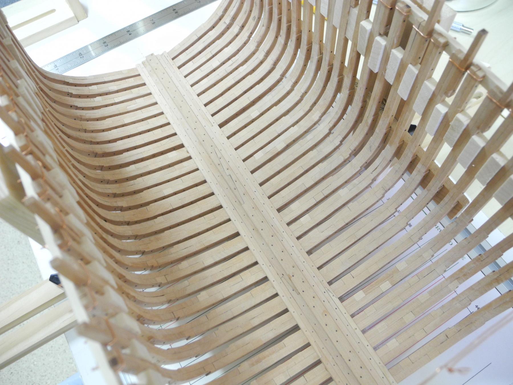
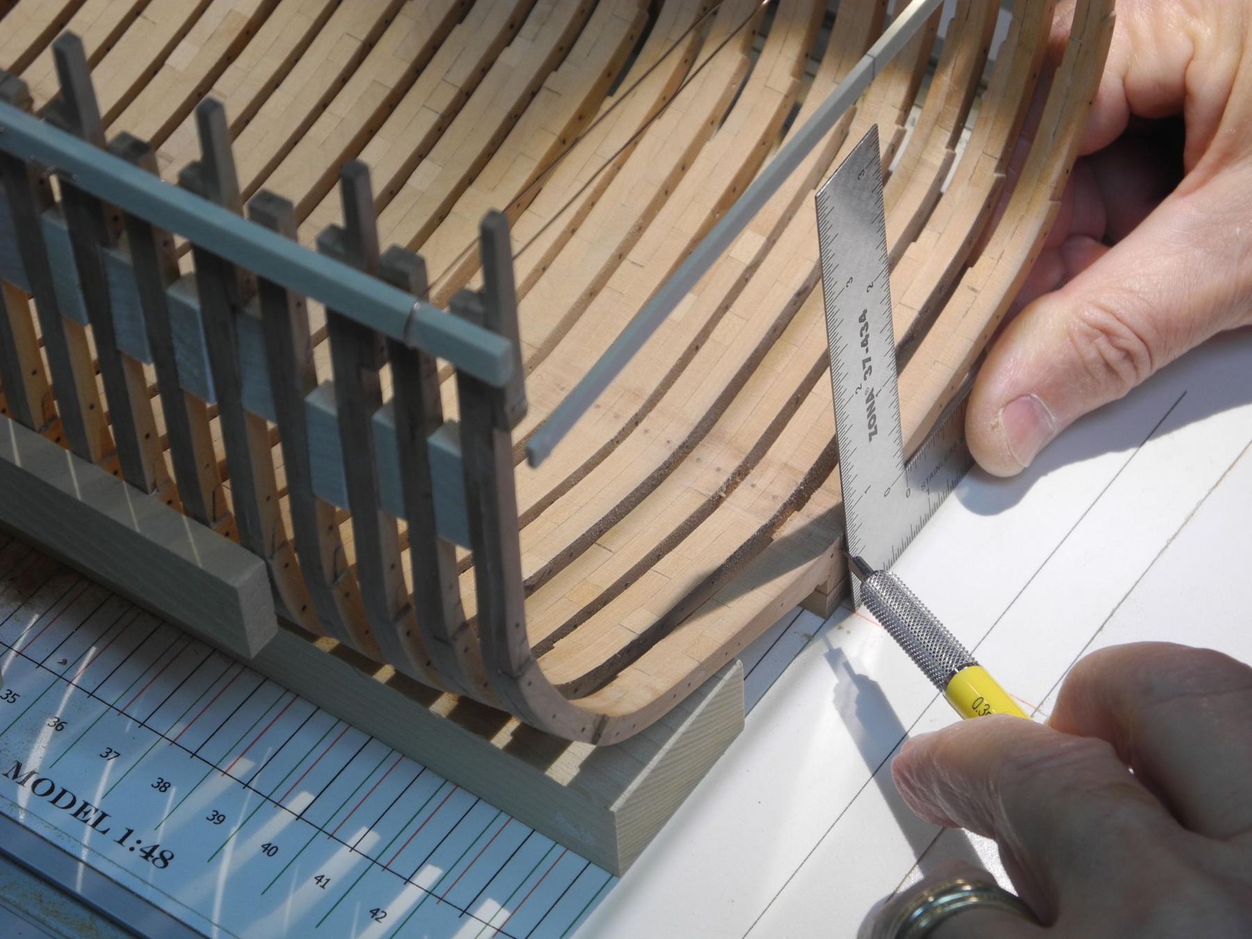
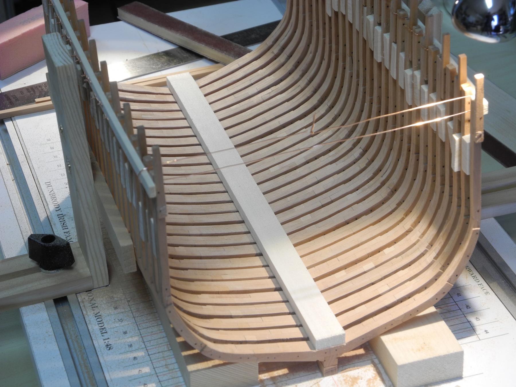
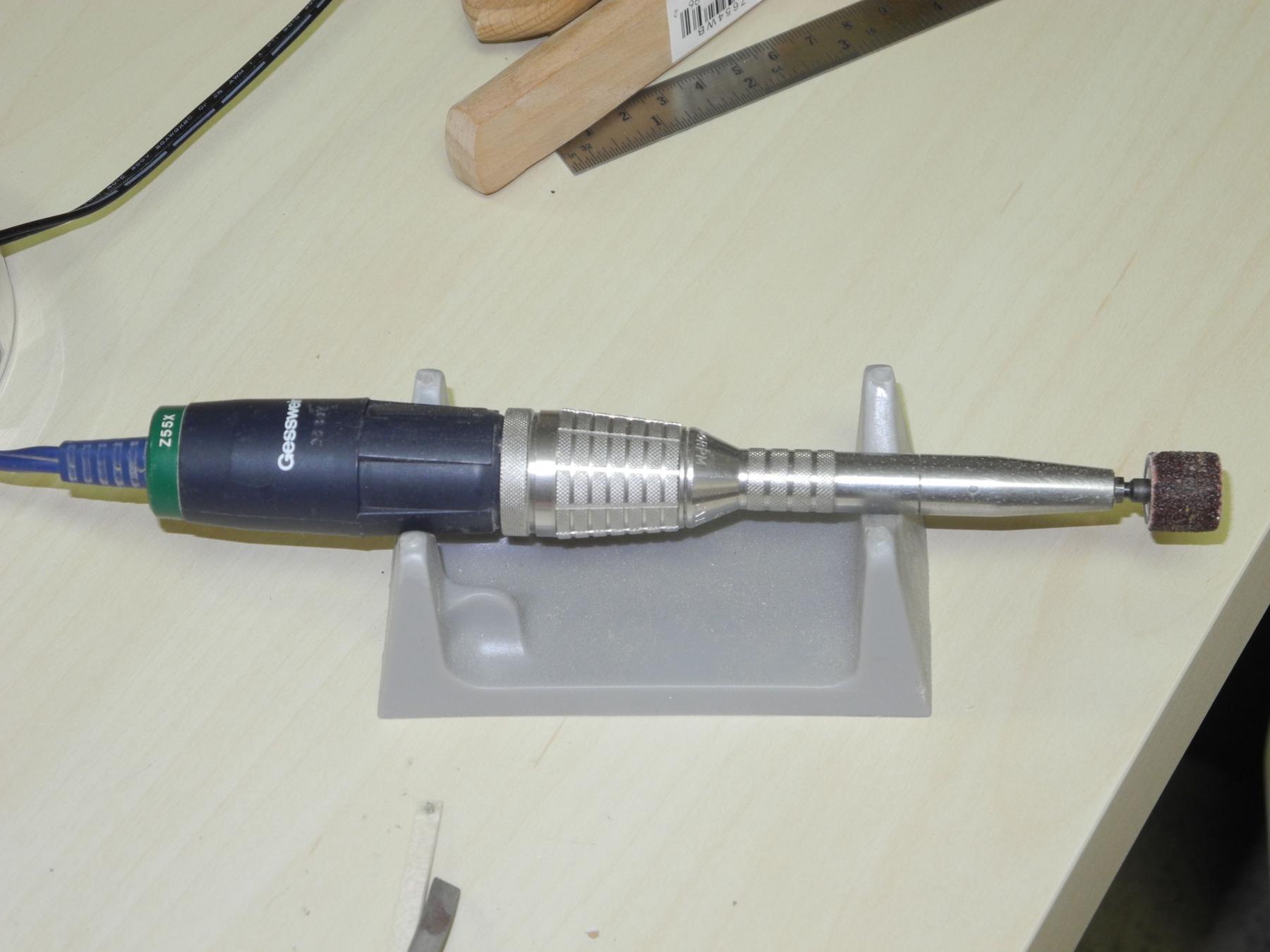
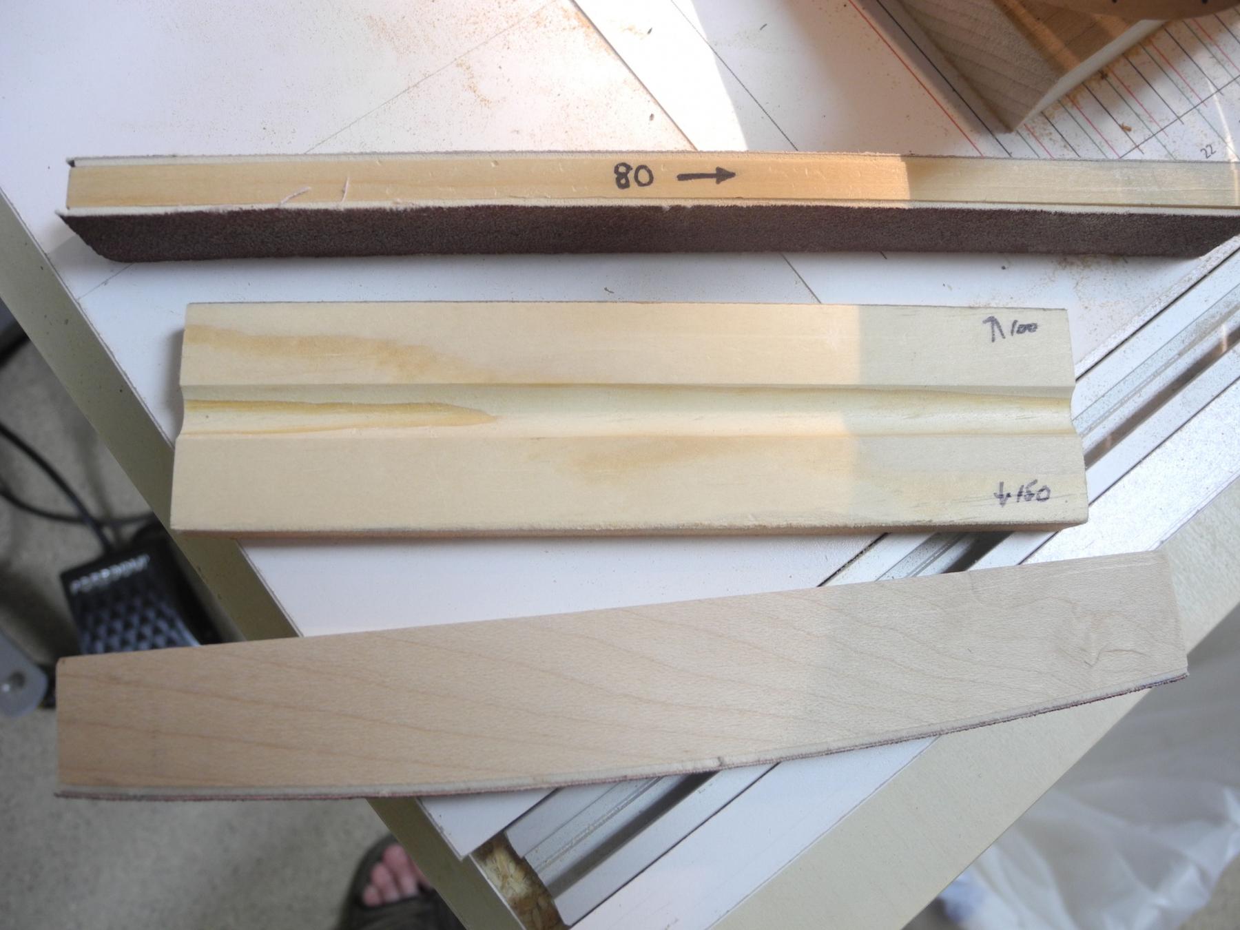
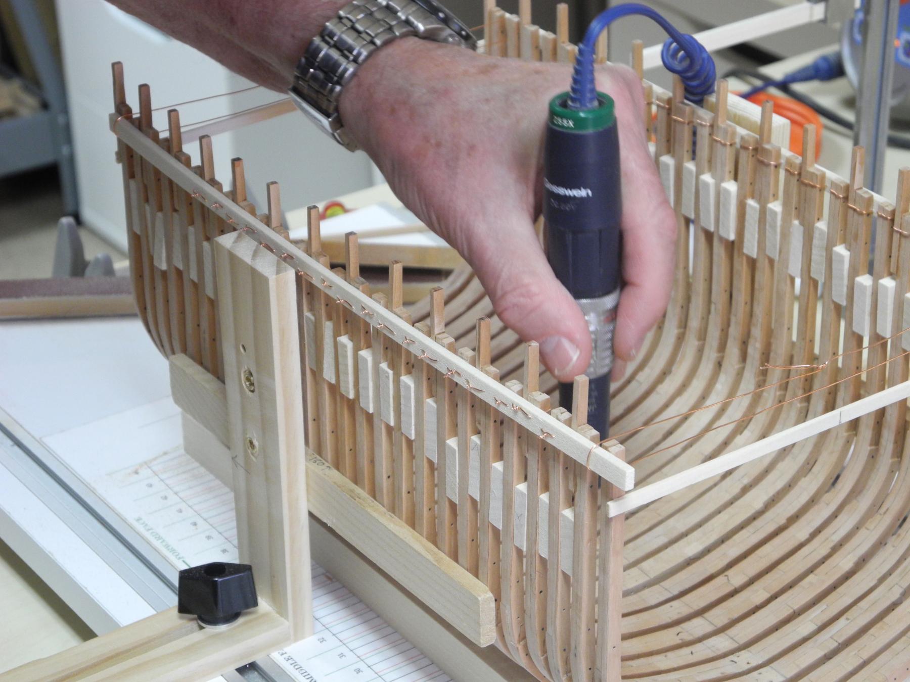
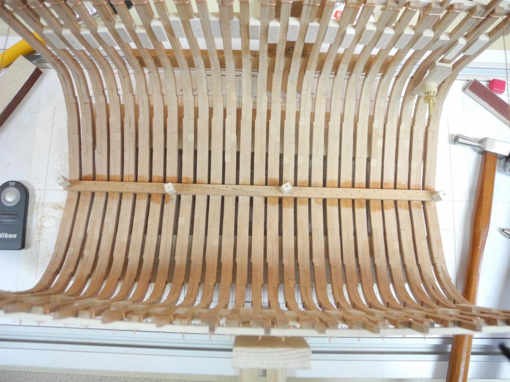
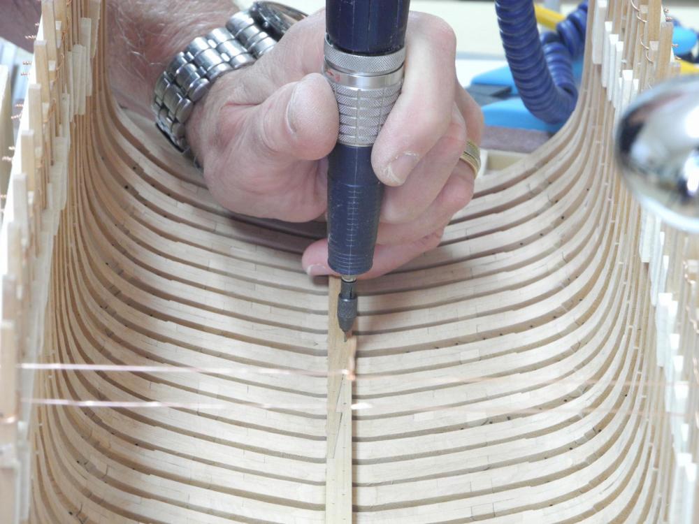
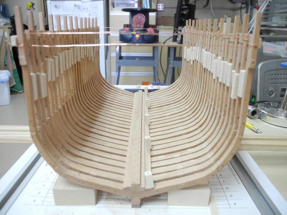
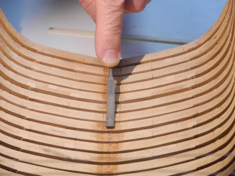
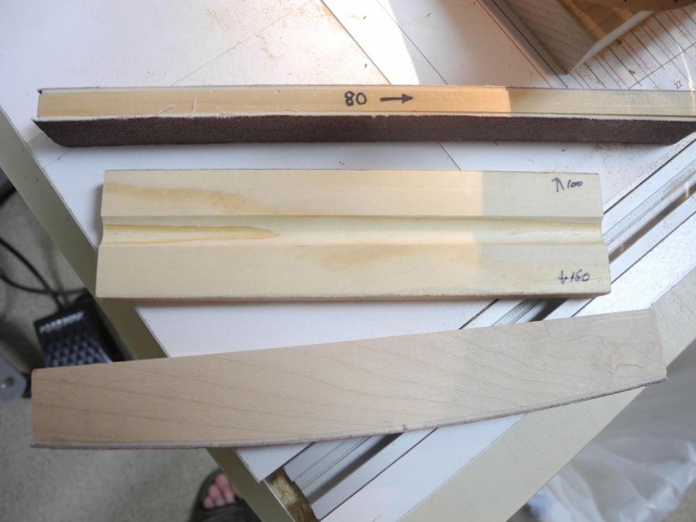
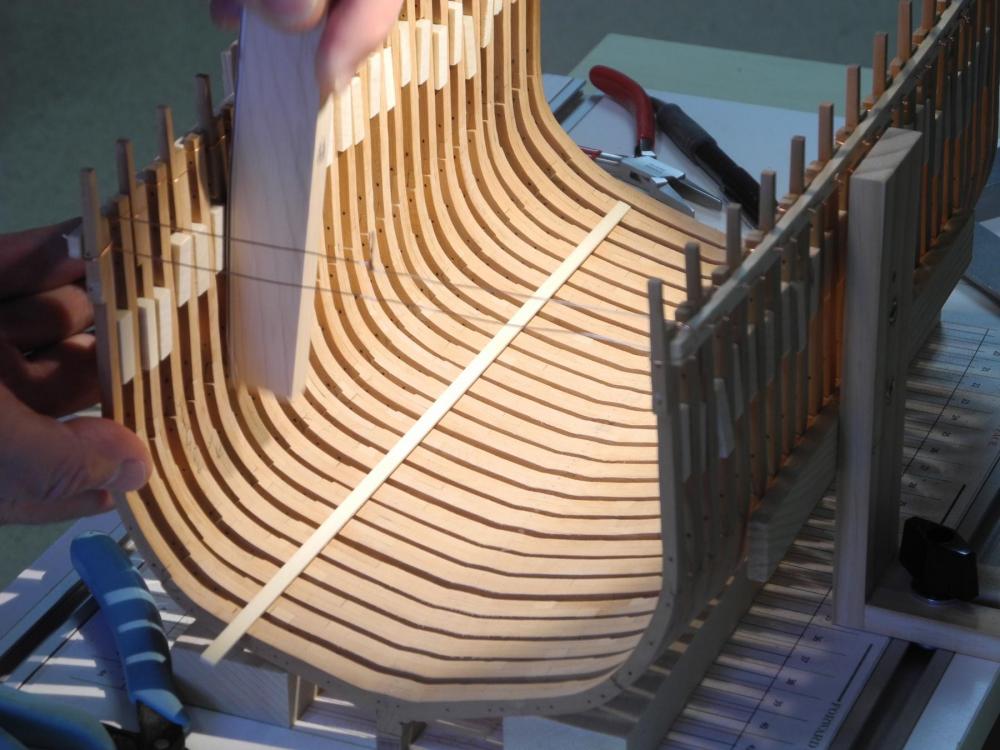
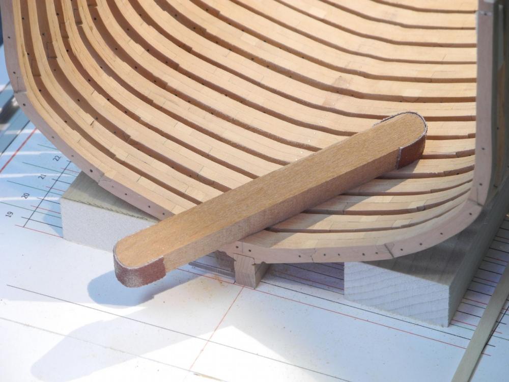
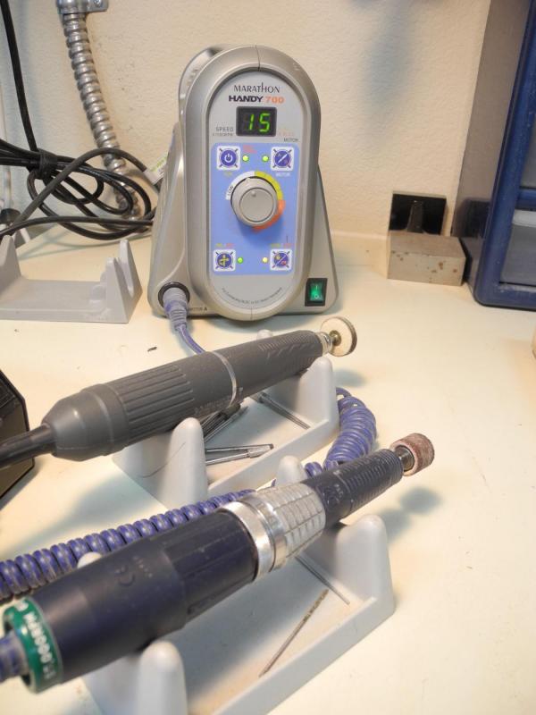
Part 16 – Prepping the Hull Once the frames were installed, a lot of odds and ends had to be addressed. First, I wanted to install a temporary Batten at the planksheer on each side. I didn’t want to make any holes in the frames at this point, so I decided to use copper wire to hold the batten securely. I measured and marked for the planksheer using a height gauge, then clamped the batten in place. I then drilled a hole in the batten on each side of every frame. I inserted copper wire into the hole on one side of a frame, wrapped the wire around and brought it out the hole on the other side of the frame. I then carefully twisted the wires until they were tight, keeping a close watch that the frame remained perpendicular. I cut away the glue on one side of each filler block as I was working, so that the frames could move in or out as required. The hull begins to taper on the fore and aft ends of the sectional model, and this shows up in the size of the 4 frames on each end of the model, which begin to gradually reduce in width. I knew I wouldn’t be able to match the required taper on the batten, so I decided to pull the ends of the battens towards the center of the hull by using copper wire. This brought the battens into proper contact with the narrowed frames and gave me a good taper fore and aft. I made sure to measure the taper on each side of the centerline to keep the hull properly shaped, then reinstalled the cross spalls. I wanted to fair the inside of the hull to the approximate height of the accommodation deck. I didn’t want to proceed above this point, since the frames were only held in place by the glue on the keel and by the battens at the planksheer. I had drilled holes for mounting bolts in each frame, but before I could insert the bolts I need to make sure the cutting down line was flat and level to take the keelson and sister keelsons. When I drafted the frames I used the sizes of the keelson and sister keelsons from the hull cross-section provided in the plans to determine the width of the cutting down line. After reviewing the topic on keelsons in the Crothers book, I decided that the sister keelsons were very undersized and that I would make them somewhat bigger. This necessitated widening the cutting down line and then tapering the frames to that flat area. Using a small square I marked the centerline on the keel. I marked the boundaries of the cutting down line using a piece of stock cut to the proper dimension, and then used that piece to check the level of the line I had sanded. Once the cutting down line was ready, I was able to proceed with installing the mounting bolts. The bolt holes were already drilled in the frames but were not yet in the keel, so I carefully drilled through the frame mounting holes and into the keel. I used 3/64 brass rods as the mounting bolts, since these are functional fasteners. These were glued into the mounting holes using epoxy, and then were snipped close to the frames. After the epoxy set I used a riffler file to smooth the bolts flush with the top of the frames. With the frames now secured to the keel I could begin fairing the frames. Even though the drafting and frame building provided fairly consistent frames I found that a few needed fairing – mainly because of some errors I made in the construction. I used my rotary tool with a Dremel sanding drum to reduce any significant high areas. The motor of the rotary tool has a removable forward piece for changing some accessories. One very useful accessory is the ‘Slender Head’, which allows the rotary tool to be used in tight areas. This allowed me to reach into the hull while keeping the sanding drum fairly level. I also used a variety of sanding sticks for the fairing. The sanding stick with the curved edge (bottom of the following photo) proved very useful in the forward and aft areas where the frames begin to slope upward. It was also useful for carefully sanding the upper areas of the frames. Sanding the tight curves in the bilge area required another type of sanding stick. With all of this sanding going on, I made sure to position my dust collector near the hull to try to capture any stray dust. It’s getting warmer in Arizona and I need to keep the windows closed and run the A/C, so the atmosphere in the shop will get pretty dusty if it’s not filtered. The next part will deal with the installation of the keelsons. Thanks everyone of following!


- 649 replies
-
- 20
-
-
- dunbrody
- famine ship
- (and 2 more)
-
Hi Patrick I'd better be careful on any future comments - you seem to like challenges! Amazing detail in such a small space. Your favorite tools must be magnifiers and tweezers. Excellent work!
-
Thanks Elijah. The repetitive work of building frames is finally over, and now the real fun begins.
- 649 replies
-
- 4
-
-
- dunbrody
- famine ship
- (and 2 more)
-
Hi Gary I'm very impressed with your work on the Naiad. I'm a big fan of Ed's work and, like you, find his books to be excellent guides. Your Naiad demonstrates their value. I plan to follow the rest of your build.
-
Thanks Druxey - that's encouraging, since I'm far from being an expert model maker! Thanks Bob - not perfect, but coming along OK.
- 649 replies
-
- 4
-
-
- dunbrody
- famine ship
- (and 2 more)
-
Thanks, Brian. I'd need to feel confident in taking it off the shipway, so I guess it depends on how much I get done before the meeting.
- 649 replies
-
- 4
-
-
- dunbrody
- famine ship
- (and 2 more)
-
Thanks Mark. I'm hoping the scrap box doesn't grow too much more, but there's still a lot of work ahead, which means many more opportunities for re-do's.
- 649 replies
-
- 4
-
-
- dunbrody
- famine ship
- (and 2 more)
-
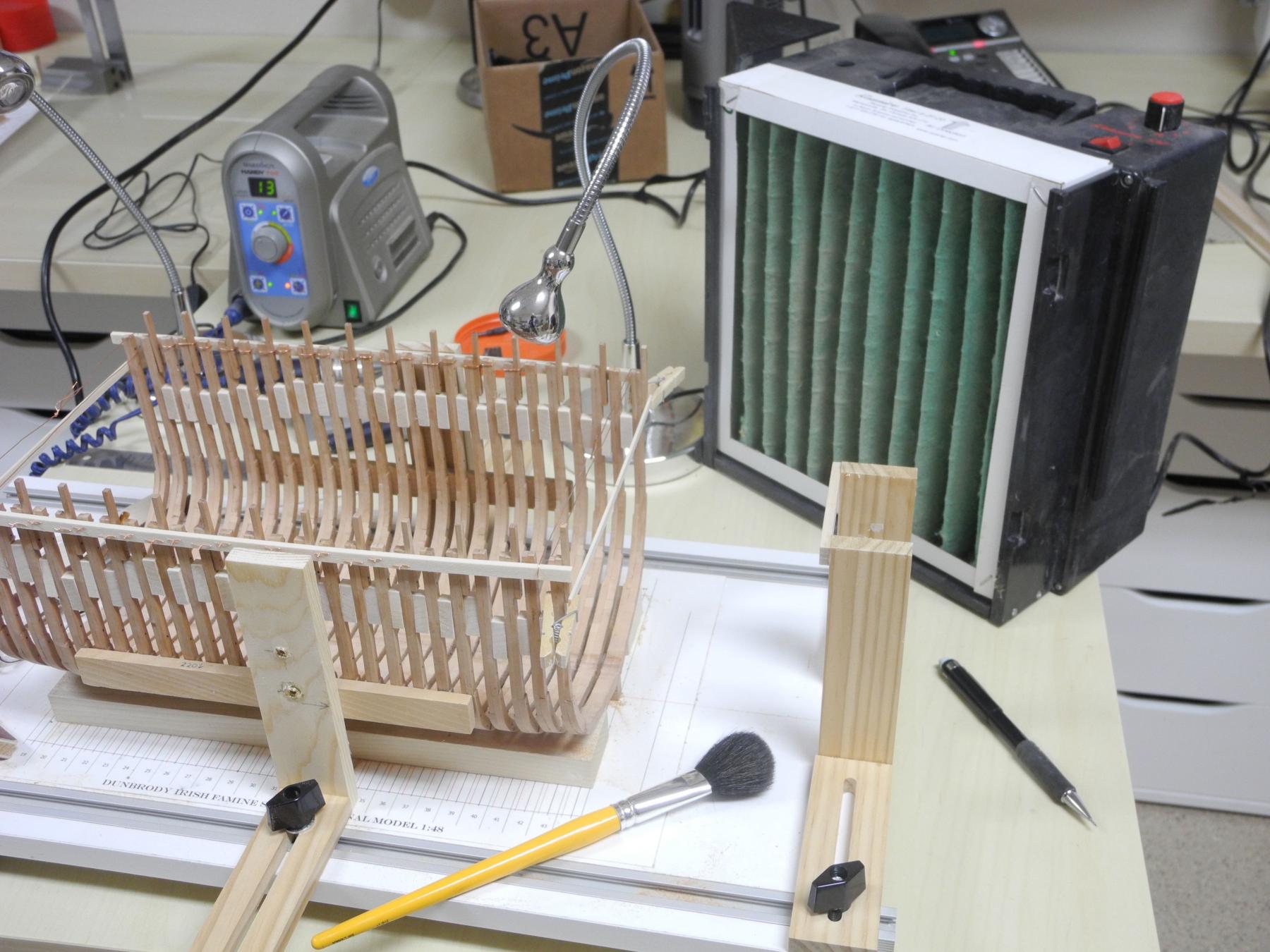
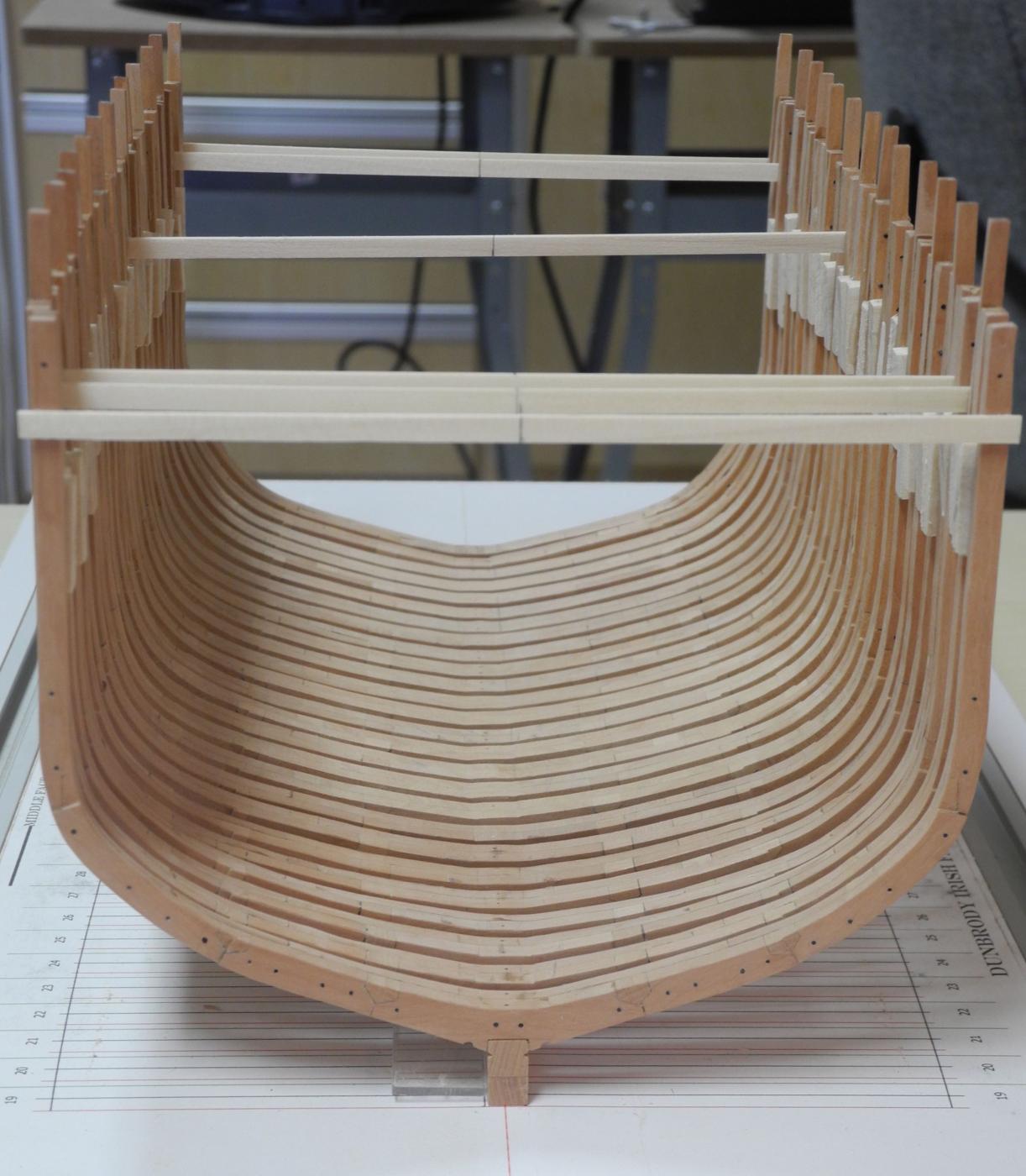
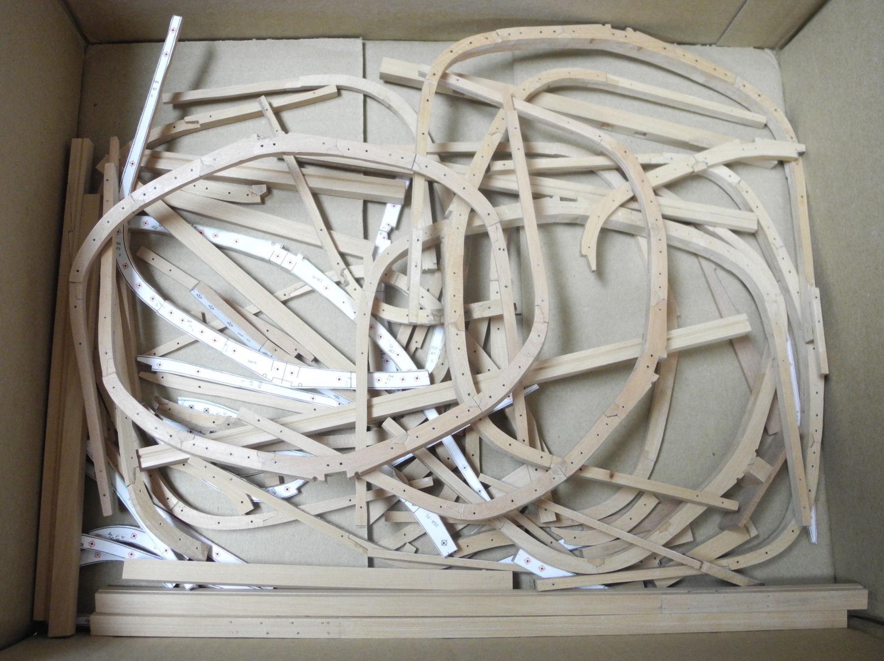
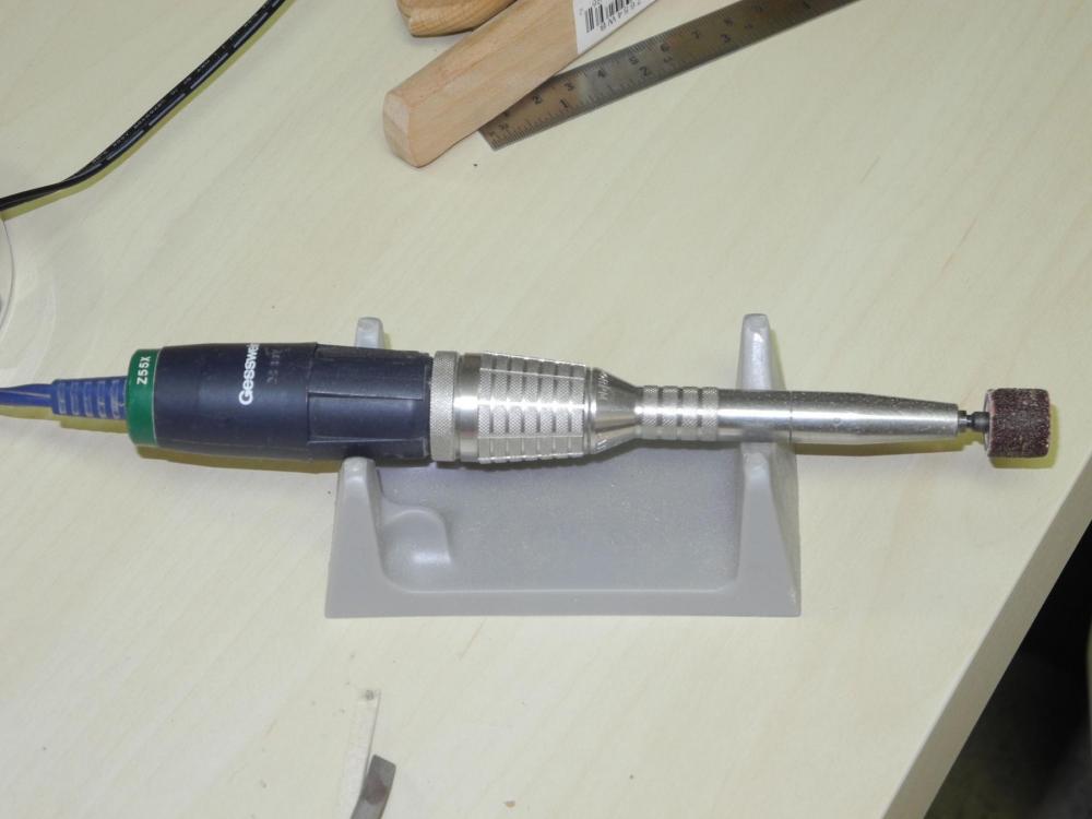
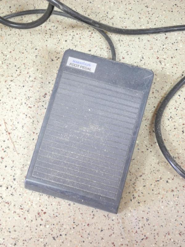
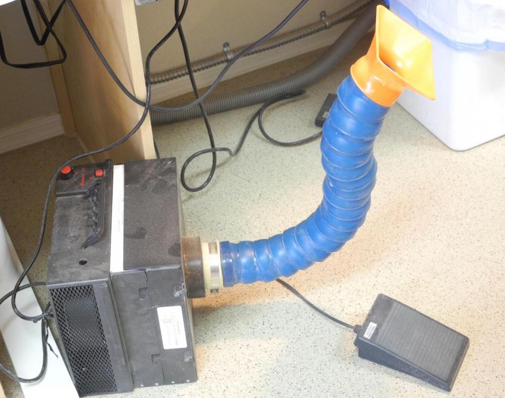
Part 15 – Installing the Frames – completed Since my last post about a week ago, I’ve been focusing on getting the installation of the frames completed. The aftmost frames have a slight bevel, primarily in the bilge area. I beveled the frames using a rotary tool I’ve had for quite a while. The tool is a Marathon Power Hand from Gesswein that I used for bird carving. Bird carving is an exercise in power carving, using a couple of different types of rotary tools. These tools work on the same principle as a Dremel rotary tool, but run much smoother and at much higher speeds. The Power Hand is capable of speeds up to 55,000 RPM. The Power hand has a variable speed foot switch, which gives me a lot of control over the grinding. The frames were sanded to the line for the forward frame sister on the outside of the frame, and then sanded to the line for the aft frame sister on the inside of the frame. Sanding on the outside was accomplished using a combination of the disk sander and the spindle sander. Sanding on the inside was accomplished using the spindle sander only. This left an area on the aft frame sister on the outside of the frame that still needed to be sanded. Similarly, the forward frame sister had an area on the inside edge that needed to be sanded. After the initial sanding mentioned above was completed, the rotary tool was then used to complete the sanding in these areas. Only the edge of the frame was sanded to the line, and then the frame surface was flattened to these lines, resulting in the bevel. The orange funnel in the photo is a port for a portable dust collector, shown in the following photo. This is also a carryover from my days as a bird carver, and is very useful for setting up temporary dust collection for tools that don’t have a dust port, like the scroll saw, milling machine, or lathe. So, after a long process, today I installed frame 19 - the aftmost and last frame in the sectional model. The following photo shows the frame clamped in place and being glued. All told, the 26 frames in the model are made up of 594 individual pieces, including the chocks. They also contain over 700 monofilament ‘bolts’. I have to admit, though, that the last week was spent redoing work on three frames that didn’t come out right (due to a senior moment I had at the end of last week). My scrap box is getting full – all told I needed to replace 5 full frames and numerous individual timbers. This has been a great learning experience. I’m pleased to have reached this milestone (while retaining my sanity, I think). Some of the next work will consist of fairing the inside of the frames, installing mounting bolts to secure the frames to the keel, preparing for the keelsons, and replacing the filler blocks with battens. I’ll post some progress reports as I proceed. Thanks everyone for following!


- 649 replies
-
- 19
-
-
- dunbrody
- famine ship
- (and 2 more)
-
Nice looking progress, Elijah. Congrats on reaching this milestone!
- 701 replies
-
- 3
-
-
- phantom
- model shipways
- (and 1 more)
-
We'll be sending it out in email.
-
Mark - next meeting is 5/21, then we'll probably end for the summer. Hope you can make it.