Mahuna
-
Posts
1,504 -
Joined
-
Last visited
Content Type
Profiles
Forums
Gallery
Events
Everything posted by Mahuna
-
 Thanks Druxey - next time I'll try using just the 99% isoproponal. I thought hot water was part of the debonding process. Although I have had experience with alcohol raising grain on soft woods when bird carving. Bird carvers use tupelo (very much like basswood), and when we think the bird has been thoroughly sanded and smooth we spray alcohol on it (saturating it) and let it sit for a while. When the alcohol evaporates the grain has been raised and the piece needs to be sanded again - this time to a very smooth finish thanks to the alcohol. This probably happens more with soft woods - I'll try it on the castello and madrone I'm using to see what happens.
- 649 replies
-
- 5
-

-
- dunbrody
- famine ship
- (and 2 more)
-
Thanks Alan. With my rate of error, I think you'll be getting even more wealthy (knowledge-wise). Hi Rich - I'd rather my brain worked harder trying to avoid the errors, instead of working to correct them. Thanks David. I complain about the errors (mostly in jest) but I'm really enjoying the challenges in this build. It's also a good learning experience - both in modeling techniques and in ship construction. Glad you're enjoying it along with me.
- 649 replies
-
- 4
-
-
- dunbrody
- famine ship
- (and 2 more)
-
Just a quick update on the Hold Timbers: After a lot of thought I decided to remove the Bilge Ceiling planks. Since they're on the port side they will be very visible through the viewing port. Add to that I'm considering lighting the inside of the model with LED's, and this will accentuate the error I made. One of my (many) objectives in working on this model is to improve my modeling skills. If that means doing something over to get it right then so be it. Once I start thinking "well, that's good enough" it probably isn't. I think I'll be able to save the planks. The water and alcohol have raised the grain, but that should be ok with a little fine sanding. After that I'll need to blacken the bolts again, but that's not a big deal. If I can't salvage the planks I'll make new ones - that will certainly reinforce the lesson learned.
- 649 replies
-
- 12
-
-
- dunbrody
- famine ship
- (and 2 more)
-
Thanks Ed. I thought I was being smart in removing the epoxy with alcohol, but I think you're right about it inhibiting the hardening. I also think I was too impatient and didn't let the epoxy harden completely before removing it. I hope I remember these lessons for next time.
- 649 replies
-
- 4
-
-
- dunbrody
- famine ship
- (and 2 more)
-
Thanks Sailor. I'll have to google the monument you mention, it sounds interesting.
- 649 replies
-
- 4
-
-
- dunbrody
- famine ship
- (and 2 more)
-
Thanks Ed. I glued the keelson bolts with epoxy and washed most of the excess epoxy off with isopropyl alcohol. This seemed to work, but smoothing the bolts with a riffler caused epoxy to load up in the file, and i haven't been able to completely clean the file. How did you avoid this?
- 649 replies
-
- 5
-
-
- dunbrody
- famine ship
- (and 2 more)
-
Hi Brian. No, I'm not doing anything with the edges. I haven't been real happy with using tinted glue, so on the planking I'll let the different hues of the wood (if any) set the planks off. Although I may change my mind as things progress.
- 649 replies
-
- 3
-
-
- dunbrody
- famine ship
- (and 2 more)
-
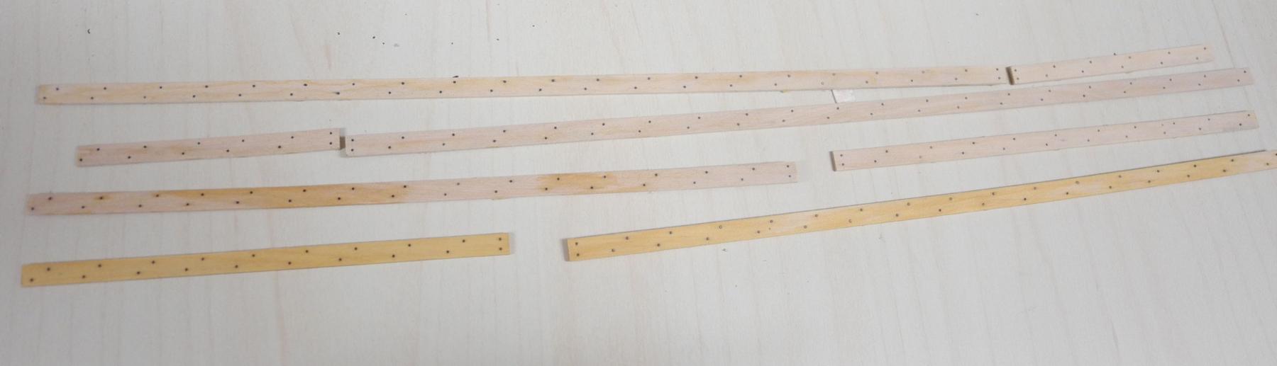
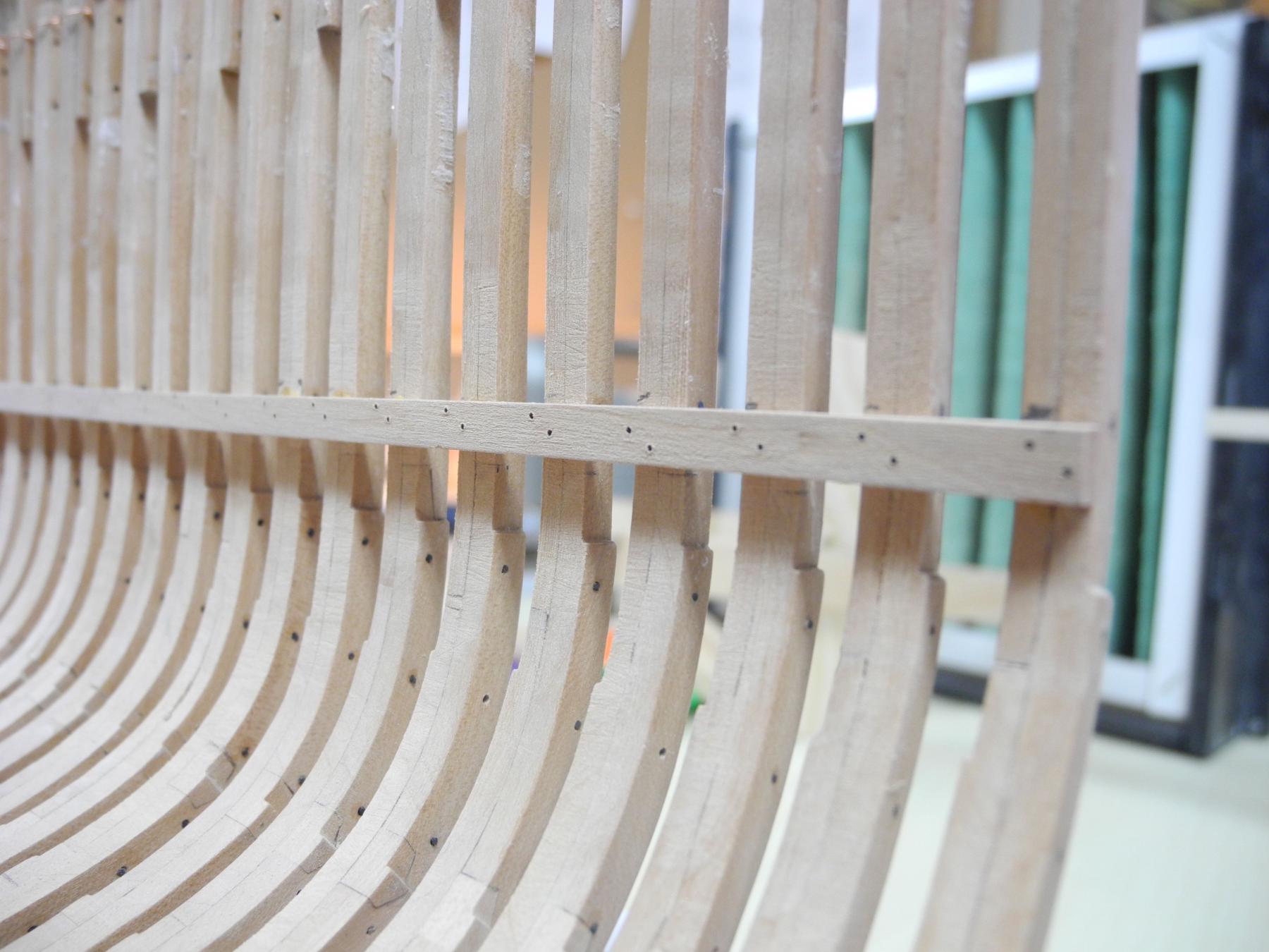
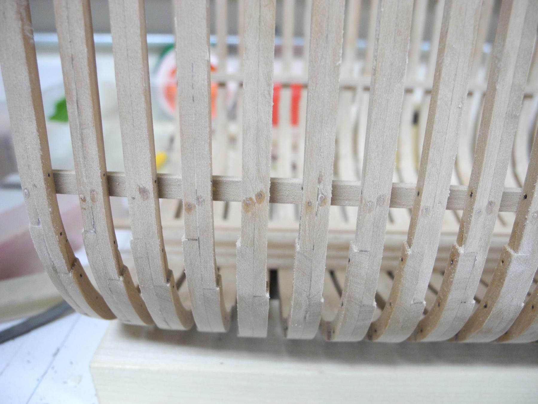
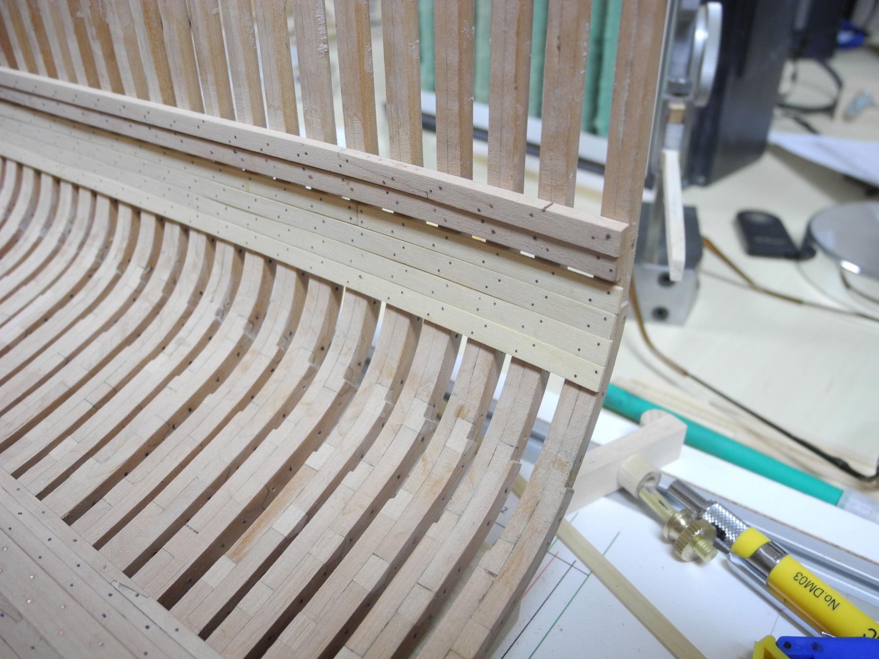
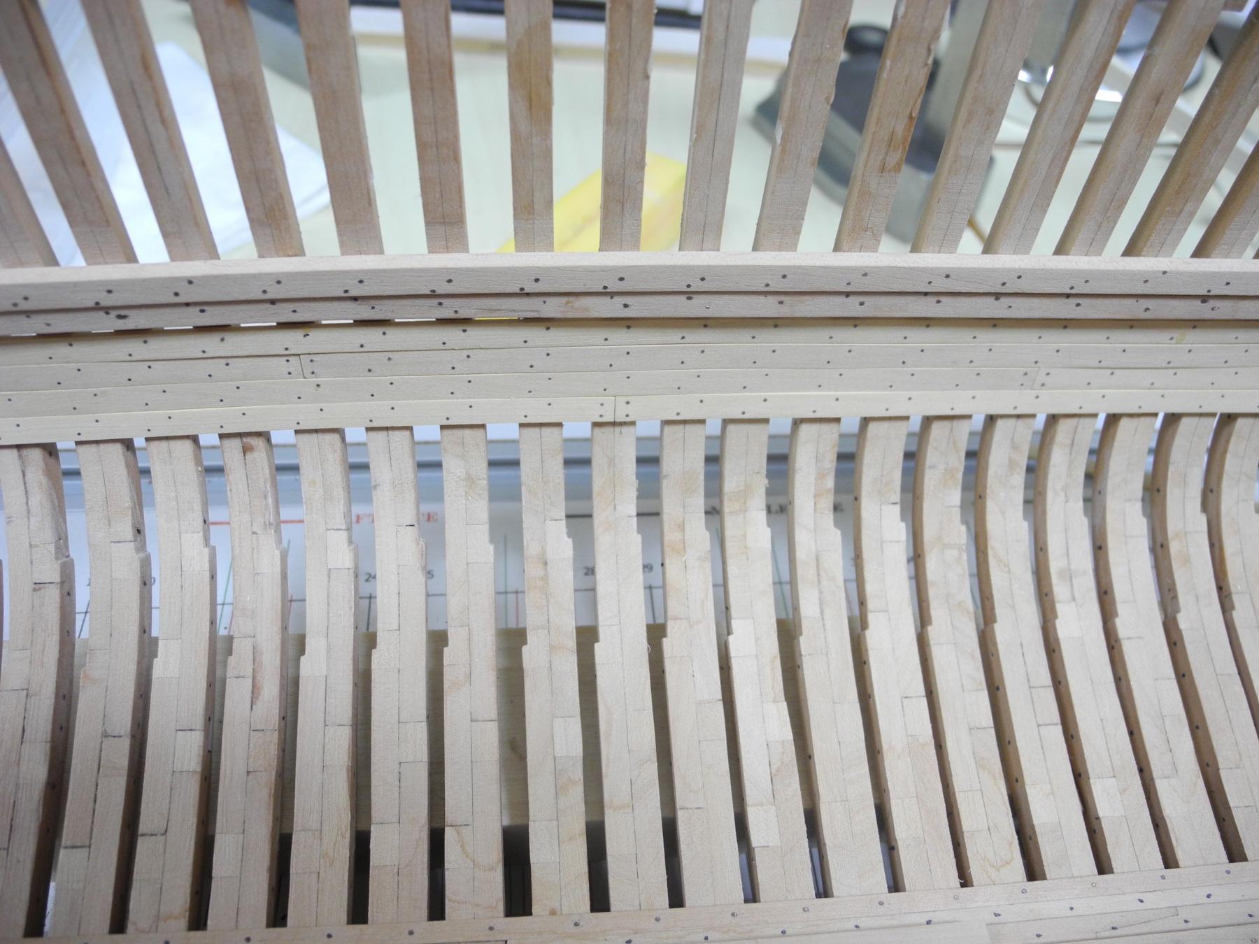
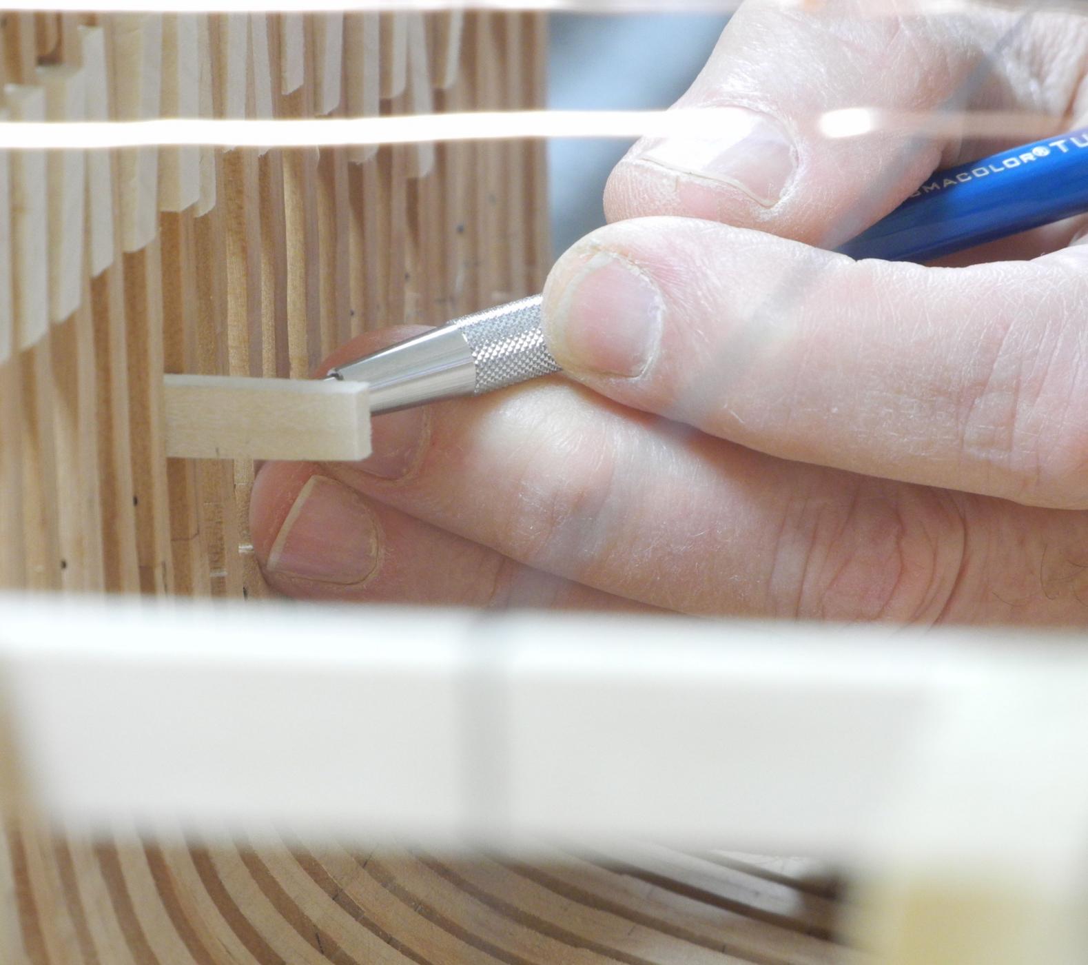
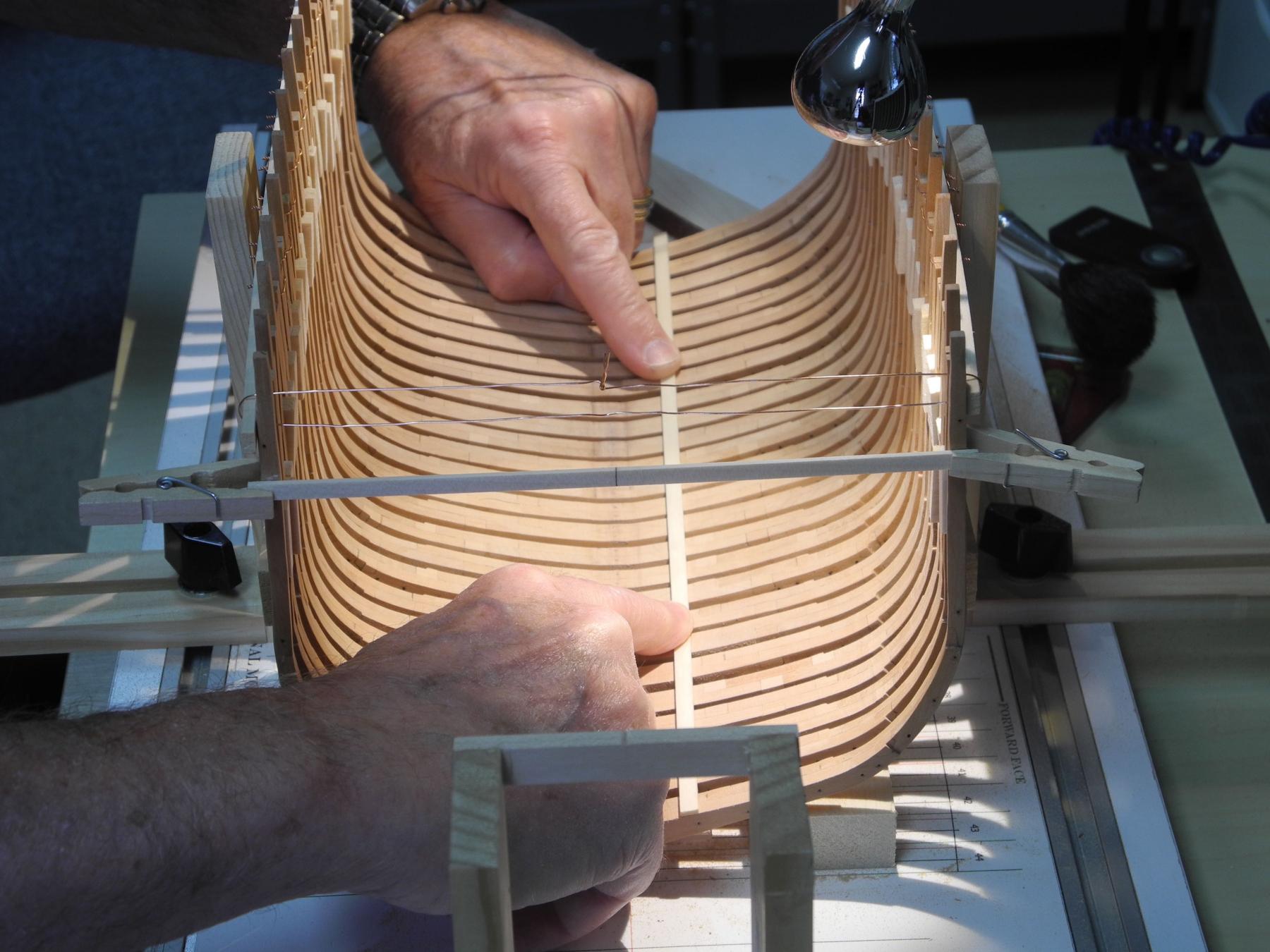
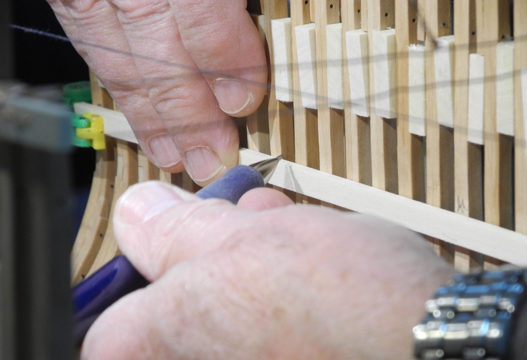
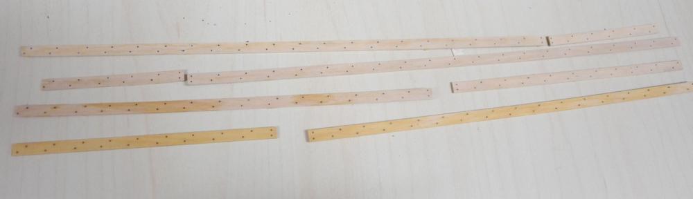
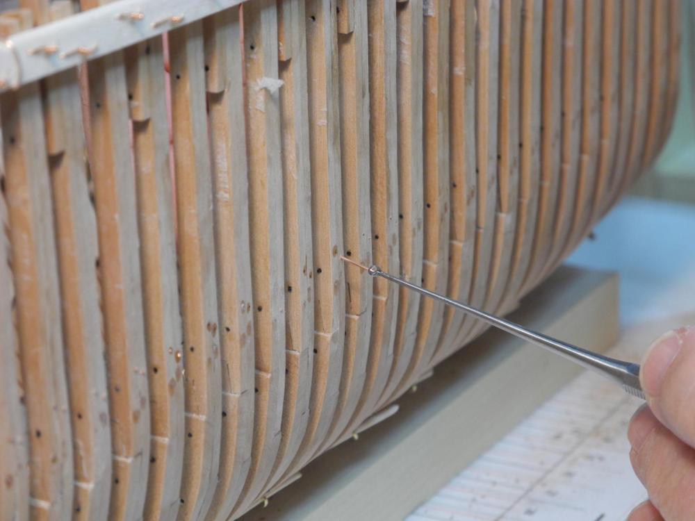
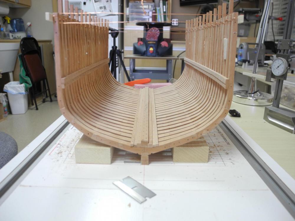
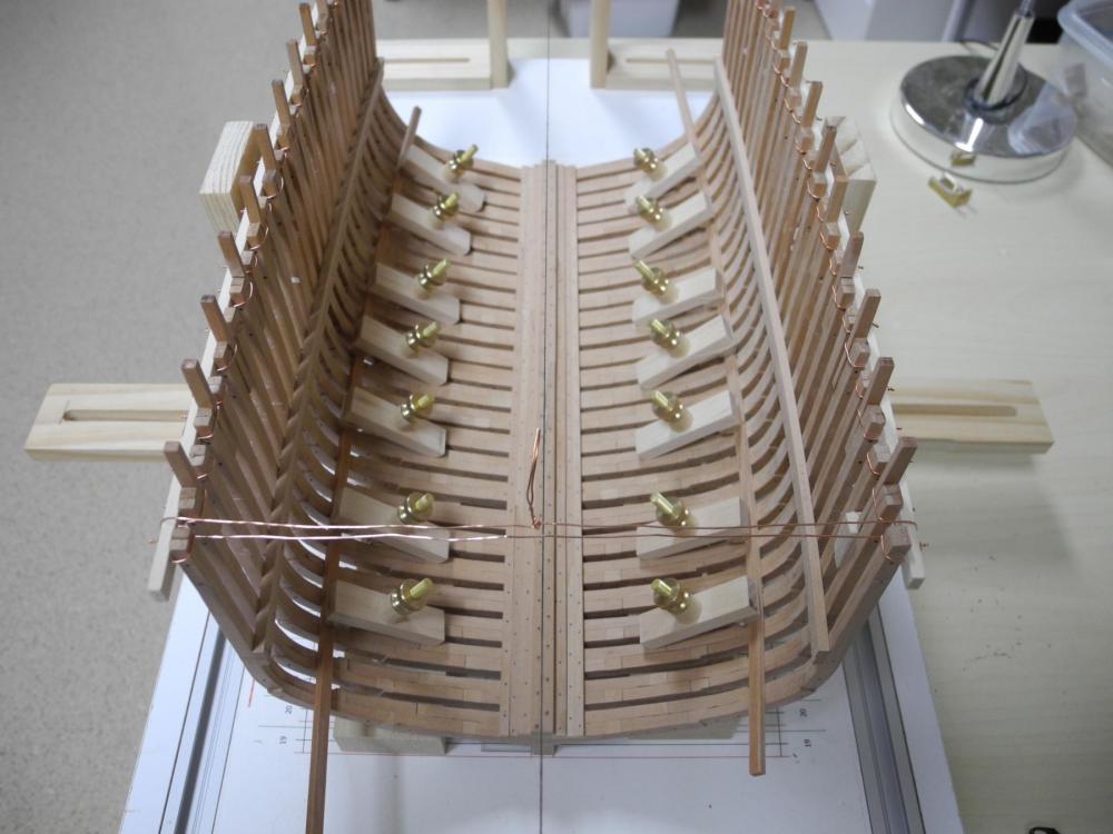
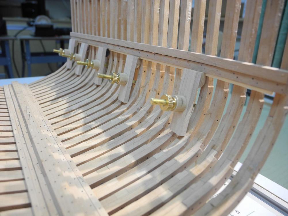
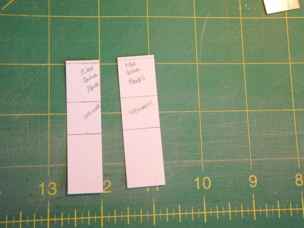
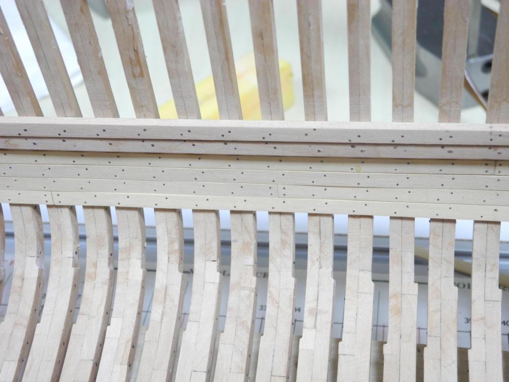
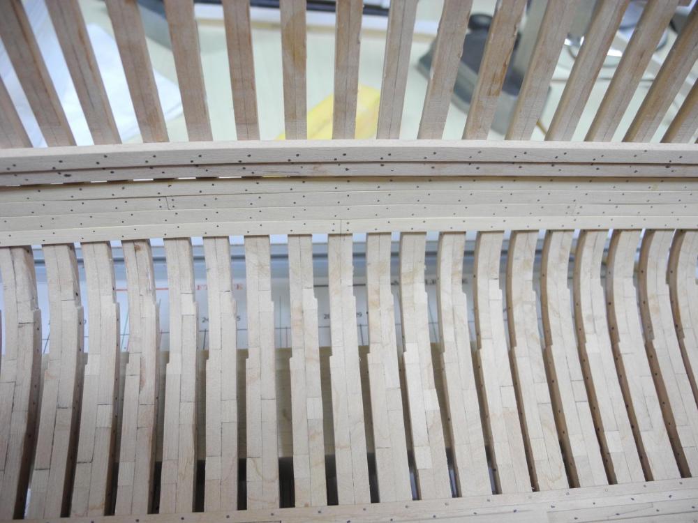
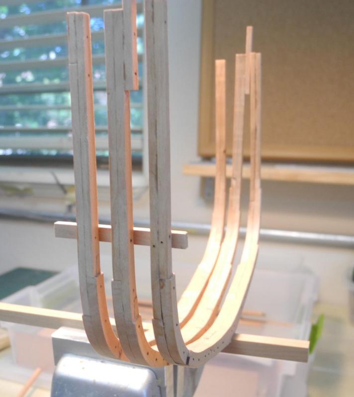
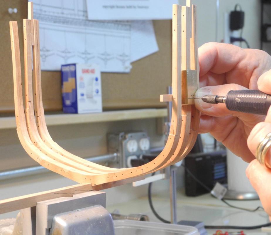
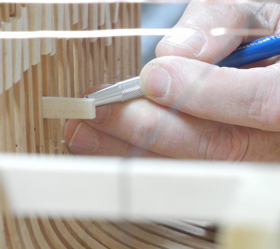
Part 20 – The Hold Timbers I used the drilling fixture discussed in Part 19 to drill holes through the lower deck clamp previously installed. Not all of the holes lined up perfectly – more of an operator problem than a problem with the fixture. I used copper wire as the bolts, feeding it through from the outside, then applying CA glue to the end on the outside and pulling it through until the glue was inside the timber. I wasn’t happy with glue stains, but the external planks will cover the bolts. Dunbrody has a deck shelf sitting on the deck clamp. The shelf is slightly larger than the clamp. These shelves were installed next, and were also bolted to the frames using functional bolts. The hull is now fairly strong after these bolts have been installed. I then tried installing the stringers. These timbers needed to bend both laterally and on their edges due to the shape of the sectional model at its extreme ends. I boiled the timbers and then clamped them in place. After gluing the stringers in place, I wasn’t very happy with the results. The shape of the stringers needed to be absolutely perfect for the adjacent timbers to lie properly, and I could see that there would be subsequent problems if I left them in place. This prompted my question about the Hold Timbers in post #212. After finding the answer in the Crothers book I de-installed the stringers using hot water and alcohol. They came off relatively easily – thankfully I hadn’t used any bolts to secure them. I then decided to work down from the deck clamp, installing the bilge ceiling strakes as the first install. Between the uppermost bilge strake and the clamp there is a small air space to allow air circulation in the hull. This space is 3 inches, which is 1/16 at the model scale. I used 1/16 square strips as a spacer, lightly gluing them in place. Once the first strake of bilge ceiling was installed this spacer could be removed. I knew the measurement for the stringer placement from the plans, but I was concerned that any errors in milling the various timbers might affect the placement. So I stacked the appropriate timbers as they would be installed and created tick strips from the actual configuration. I used these strips to verify the stringer locations – they will be at the correct height. The model will have a viewing port on the starboard side of the hold, so the bilge ceiling strakes will be only partially installed on that side. I decided to focus on the full timbers on the port side first. The bilge ceiling strakes (as in all of the planking for the Dunbrody model) are made of Castello. I drilled bolt holes in the bilge ceiling strakes and installed and blackened the fastening bolts before the strakes were installed. The installation of the strakes was fairly simple, using the planking clamps discussed earlier. I made some mistakes in not clamping the bilge ceiling strakes properly, and I’m not totally satisfied with the way they lay. I may decide to remove the strakes and re-install them. I'll sleep on it and decide tomorrow. Thanks everyone for following!


- 649 replies
-
- 18
-
-
- dunbrody
- famine ship
- (and 2 more)
-
Thanks Mark. I think each meeting (besides being an enjoyable social gathering) provides at least one of us with an answered question, a new technique, or an idea on tools.
- 649 replies
-
- 4
-
-
- dunbrody
- famine ship
- (and 2 more)
-
On re-reading chapter 12 of the Crothers book (Stiffening the Hull; Hold Ceiling) I found the following and I think it's the answer to my question: "The stringer, in general, ran parallel with the lower deck, though at the extremities of the vessel this was not true due to the diminishing size of the knees ..." Since the model is of the midship area, I think my assumption of the stringer being parallel to the clamp is correct. This would imply that the upper 'second stringers' and the bilge ceiling strakes would also be parallel. I would also proceed with keeping the lower 'second stringers' parallel for uniformity, and would only taper the floor ceiling strakes where necessary. Still looking forward to any comments/corrections.
- 649 replies
-
- 6
-
-
- dunbrody
- famine ship
- (and 2 more)
-
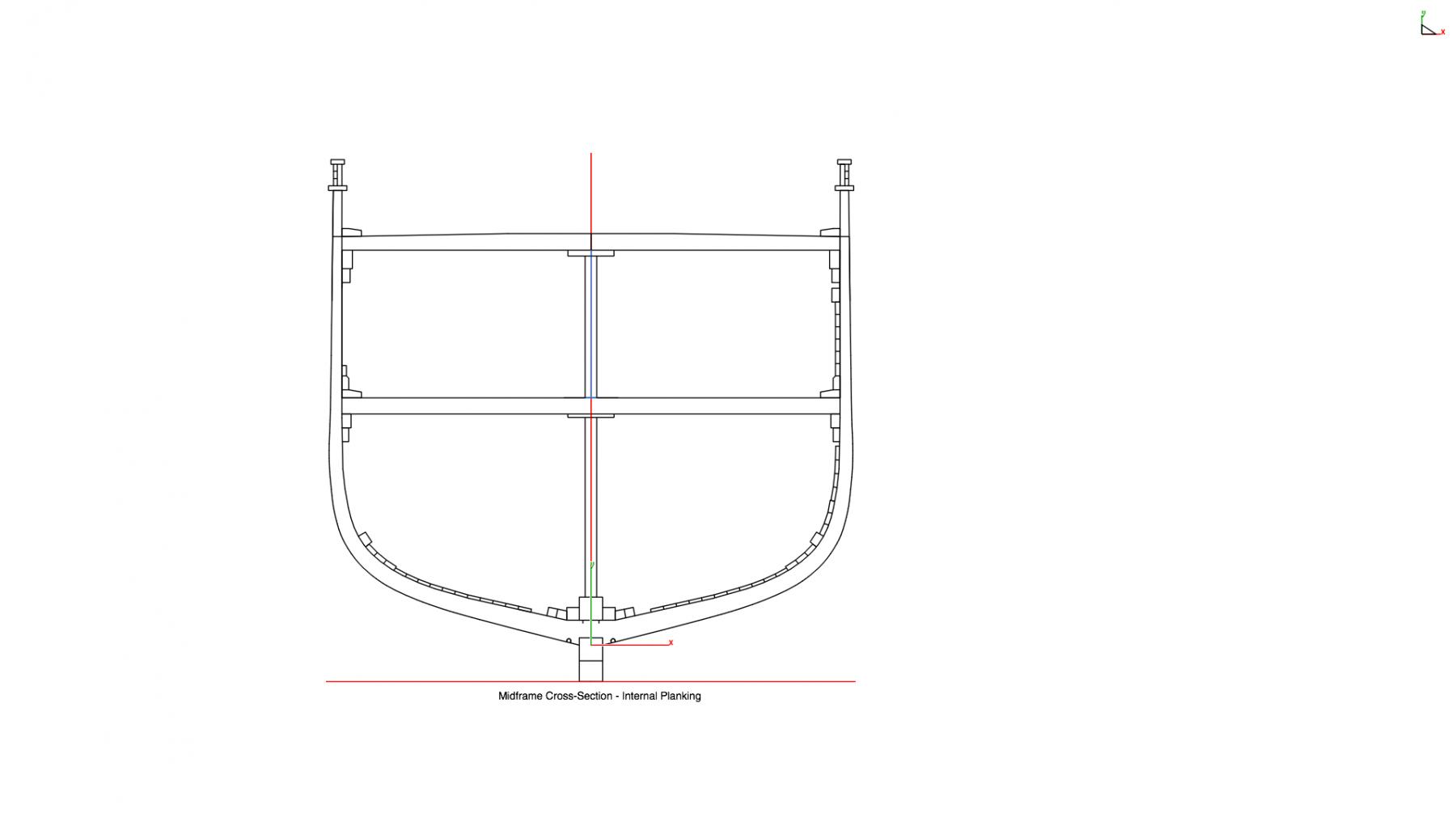
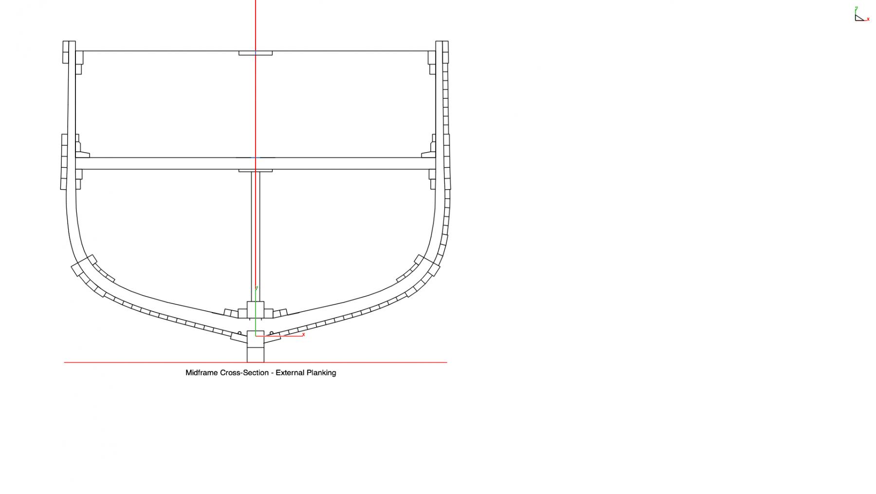
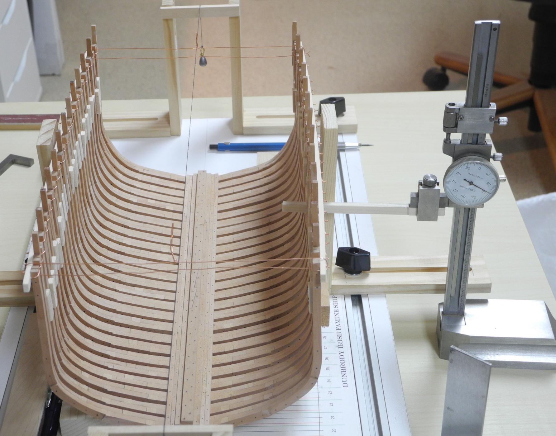
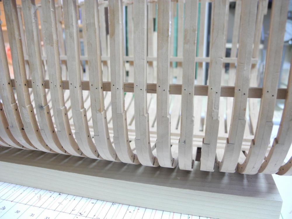
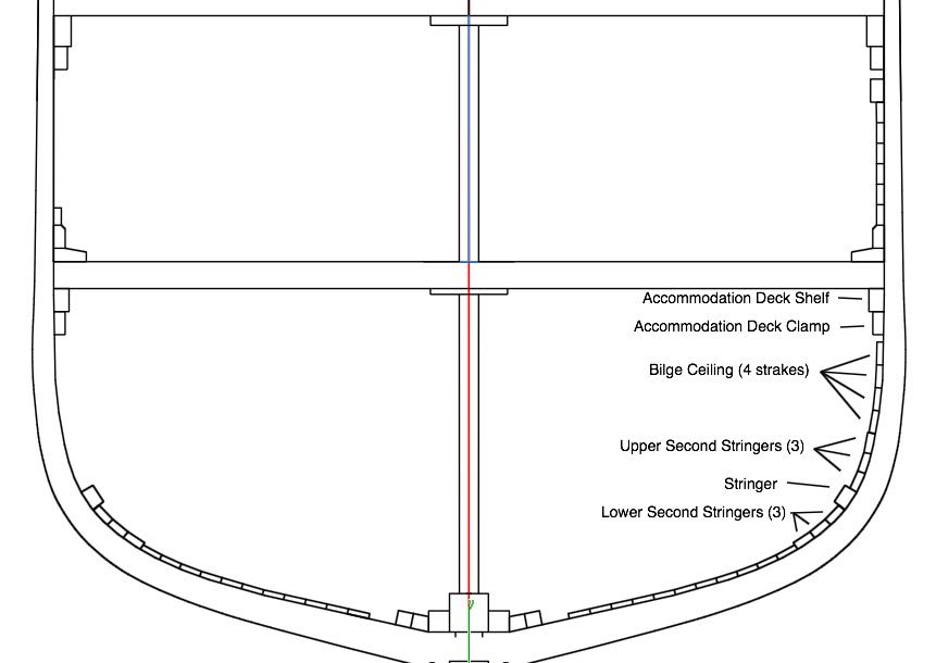
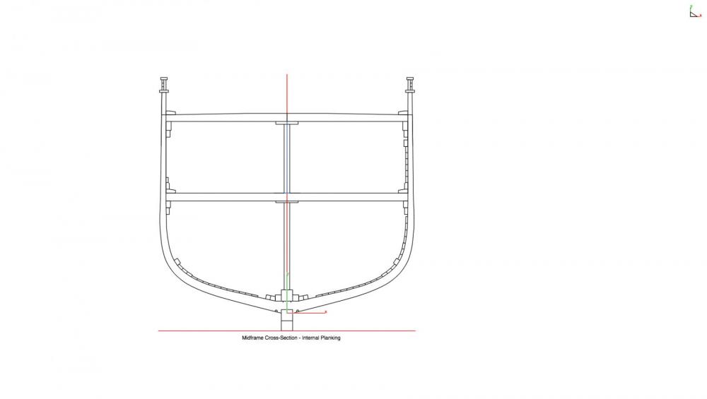
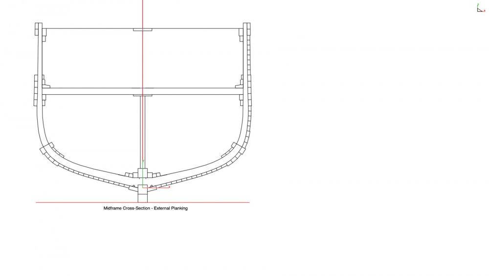
HOLD TIMBERS - QUESTION I've been working on the hold timbers, and need some help/advice before I proceed further. Dunbrody has a deck clamp with a shelf above it. Naturally, these need to be aligned with the accommodation deck, so that the top of the shelf is at the height of the bottom of a deck beam. Below the deck clamp is a small air space, then 4 strakes of bilge ceiling. Under the ceiling is a striger configuration - 3 'second stringers', the stringer itself, then another 3 'second stringers'. Finally, there are 11 floor ceiling strakes and then a limber strake. I've illustrated this configuration in the following photo. I've been assuming that the stringer arrangement, being structural timbers, should be parallel to the deck clamp/shelf arrangement. This would mean that the bilge ceiling would be parallel as well, and that only the floor ceiling strakes would taper toward the bow and stern. I've installed the deck clamp/shelf and the main stringer on each side of the model, and before I go further I would greatly appreciate hearing if my assumption is correct, or if I should taper all of the hold timbers under the deck clamp/shelf. Thanks for following, and thanks for your input.
- 649 replies
-
- 7
-
-
- dunbrody
- famine ship
- (and 2 more)
-
I like it this way, Patrick. As you say, it looks lived in. Now, if there were some towels lying around .... oops, there we go again. By the way, have you ever used the lead foil from the neck of a wine bottle to serve as a fabric? It shapes really well and holds the shape. It's also a great reason to open another bottle of wine, as though we need a reason.
-
Thanks Patrick. I consider this more a 'diary' than a tutorial. It describes the way I do things, including all the do-overs.
- 649 replies
-
- 5
-
-
- dunbrody
- famine ship
- (and 2 more)
-
Hi David - welcome aboard, and thanks for that very interesting photo. I have been to Westport several times, but haven't been there since the early 90's. I don't recall seeing this monument - it might be fairly new. The plans for Dunbrody are from the Ships in Scale magazine, and I recall seeing a POB version in that magazine a few years ago - built by a couple of modelers who worked together on it. Without showing the emigrants experience it's a fairly ordinary ship - that's why I'm doing the sectional model. I plan to show the living accommodations for the emigrants.
- 649 replies
-
- 4
-
-
- dunbrody
- famine ship
- (and 2 more)
-
Thanks Brian - now I get it. It's fairly similar to what I've made, but the four tabs instead of two might make a difference, both good and bad. On the good side it would be a closer fit with less chance of it moving around. On the not so good side it might limit where it can be used. I had to reverse mine in some spots due to the pesky filler blocks (they've now been removed since the clamps are in place and secure).
- 649 replies
-
- 5
-
-
- dunbrody
- famine ship
- (and 2 more)
-
Hi Brian - I guess I didn't understand your idea. I'd love to hear it again - always looking for different and better ways of doing things. Excellent point, Druxey. Thanks, I'll be sure to do that.
- 649 replies
-
- 4
-
-
- dunbrody
- famine ship
- (and 2 more)
-
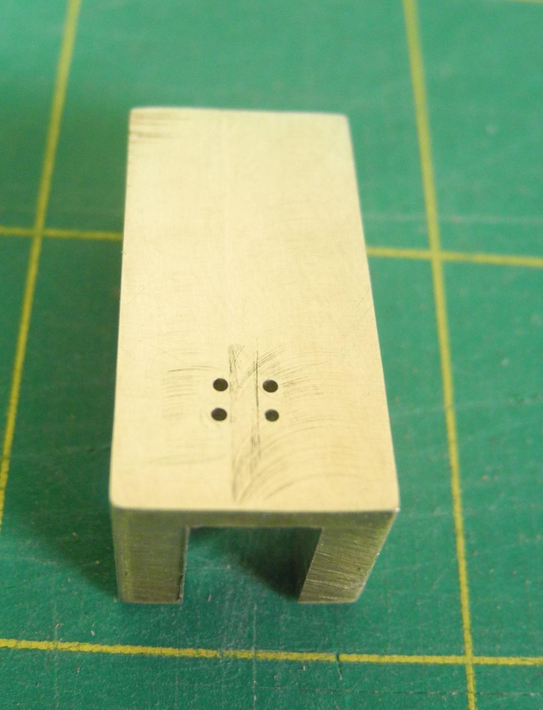
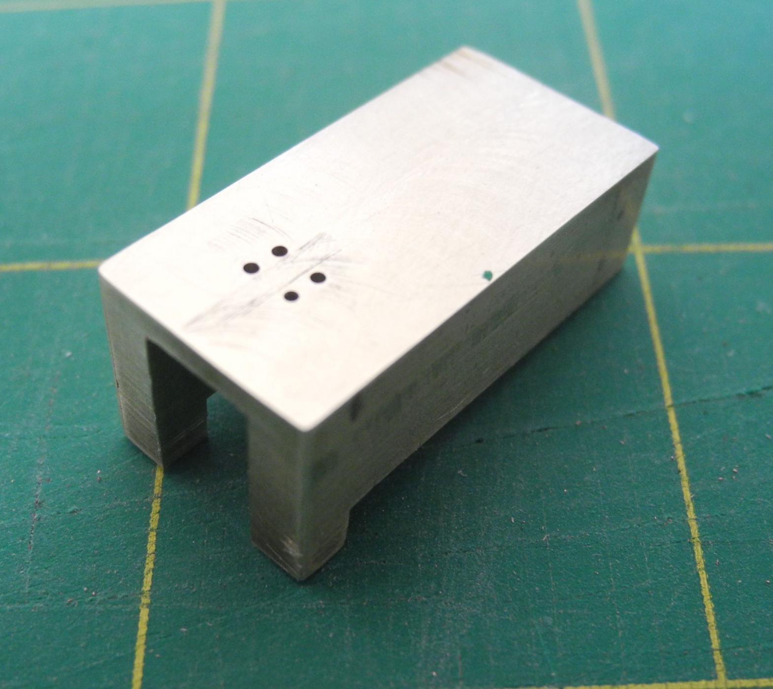
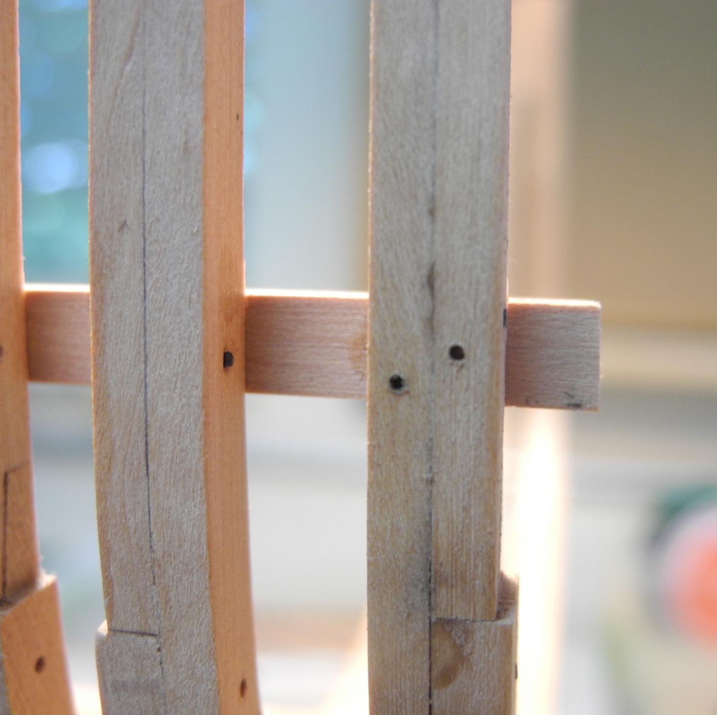
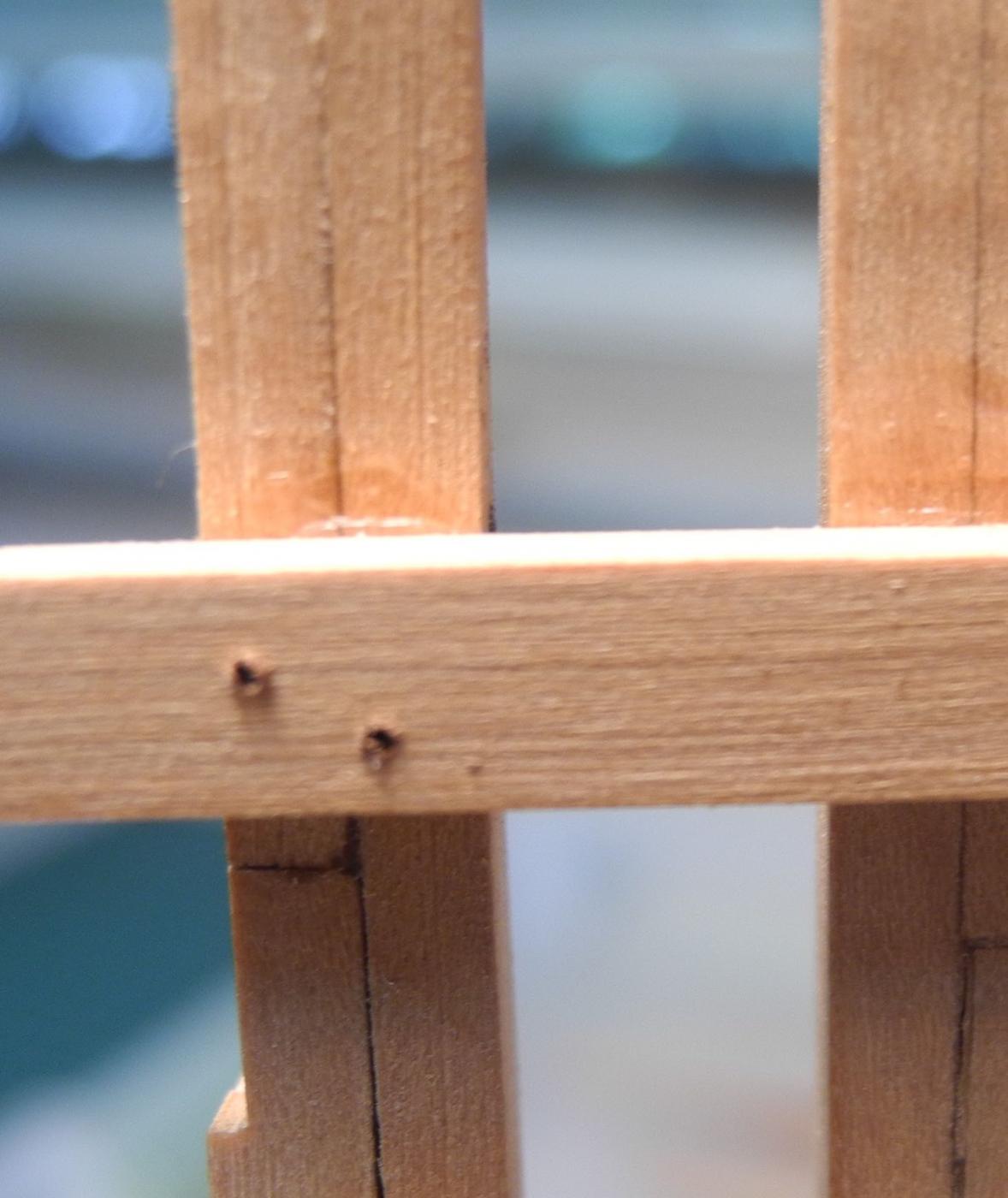
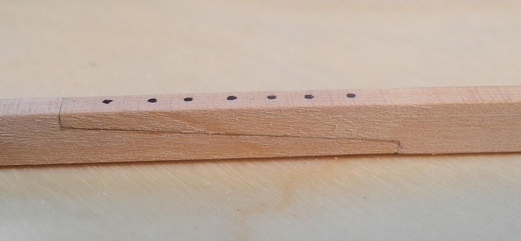
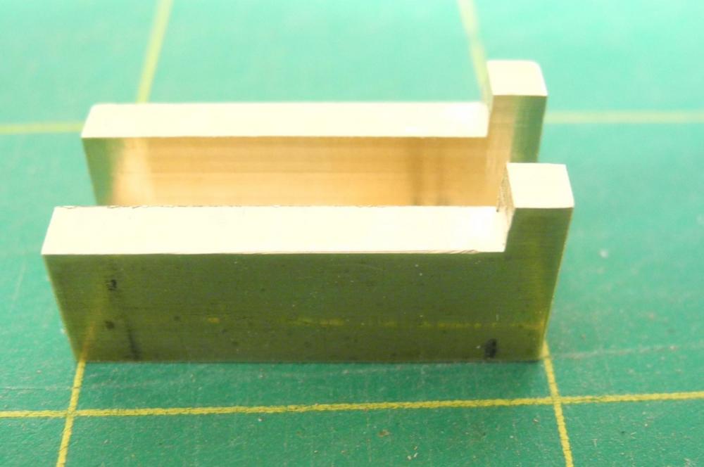
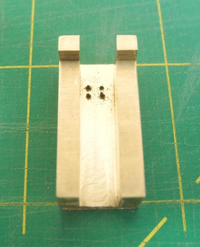
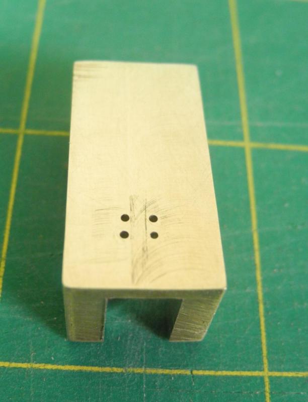
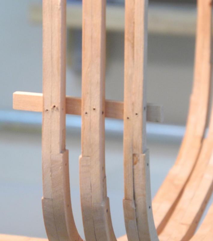
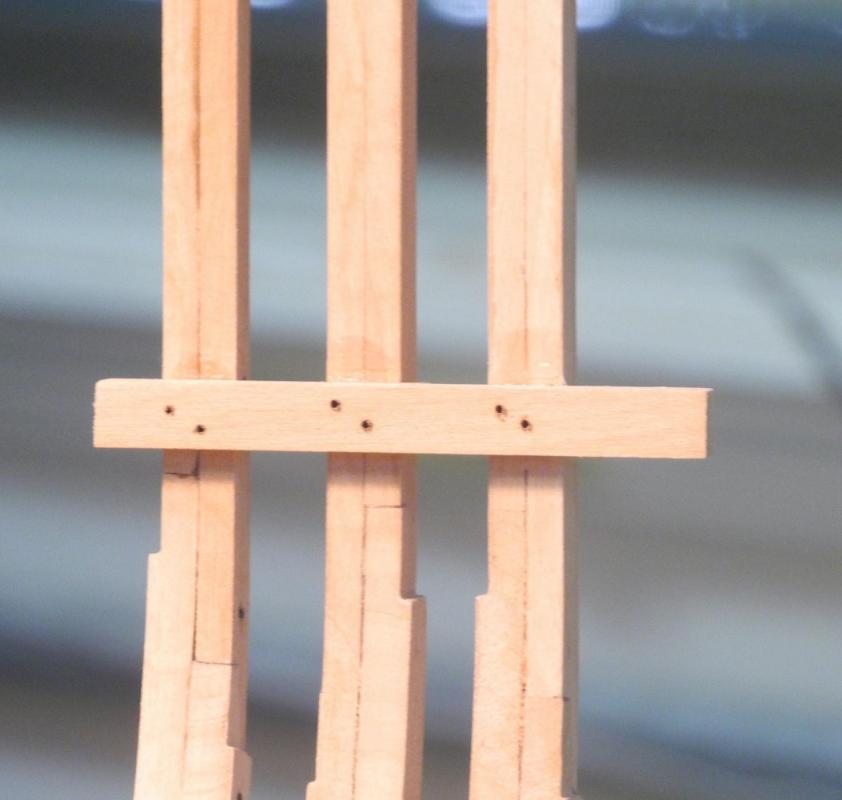
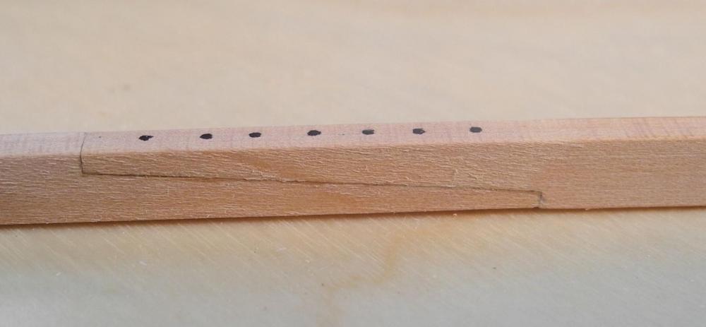
Part 19 – The Lower Accommodation Deck Clamp – Cont’d The Lower Accommodation Deck Clamp is a key structural component for the model and needs to be bolted through the frames as well as being glued. In addition to being functional bolts, these bolts also need to be properly positioned and uniform for a good appearance. Since my last post I’ve been trying to decide how to drill for these bolts. At first I thought I’d lay out and drill all of the bolt holes on the clamp before gluing the clamp to the frames. Then after gluing I would use the pre-drilled holes as guides to drill through the frames from the inside of the ship. The problem with this approach is that my rotary tool won’t fit inside the hull, so this would require using a pin vise to finish the drilling. I could do this, but the clamps aren’t the only timbers that need to be bolted through the frames. This would be a lot of manual drilling. At our ship modelers club meeting on Saturday I described my issue to the other members, and several of them suggested using some kind of a jig to align the holes. We discussed a few approaches, and I decided to make a metal drilling fixture – a wood fixture runs a greater risk of the holes becoming deformed by the constant drilling. I have a brass bar that is 1 inch wide and half an inch thick, so I decided to use a piece of that for a drilling fixture. I milled tabs on one end. These tabs would allow me to hold the fixture against the deck clamp. I milled a groove in the fixture that would fit over the frame. I drilled four holes in a square format using a #72 drill for 1.25 inch bolts. Even though I will only drill 2 diagonal holes per frame, having the four holes would let me change the diagonal on opposite sides of the ship. Making the fixture took a little over an hour, and I had calculated that manually drilling 52 holes in a single clamp would take more than that. If I can use this fixture for the eight clamps in Dunbrody I’ll have saved considerable drilling time. I didn’t want to use the fixture on the real clamp before testing it, so I used some of the discarded frames from the scrap box to set up set of test frames. I think this testing setup will come in handy for more testing in the future – now I feel much better about my scrap bin! My first test was to drill through a single frame. I was pretty happy with the results. The first photo is the holes from outside. And the next photo is of the holes viewed from inside the hull. Using the fixture is fairly simple. I drilled the holes in all of the test frames, and was happy to see they lined up pretty well. So now I can proceed with gluing the Accommodation Deck Clamps in place. A big Thank You to my fellow club members for getting me thinking the right way – and thanks to everyone for following.


- 649 replies
-
- 17
-
-
- dunbrody
- famine ship
- (and 2 more)
-
Super, Patrick. Your work continues to amaze me - you fit so much into a tiny space. On first viewing the photo with the apple I thought "that's an amazingly large apple!"
-
Filling - How do you do it?
Mahuna replied to mikiek's topic in Painting, finishing and weathering products and techniques
I use wood dust and glue for small areas like a seam that is too big. Since you're going to paint the hull, you might try acrylic modeling paste to fill in depressions.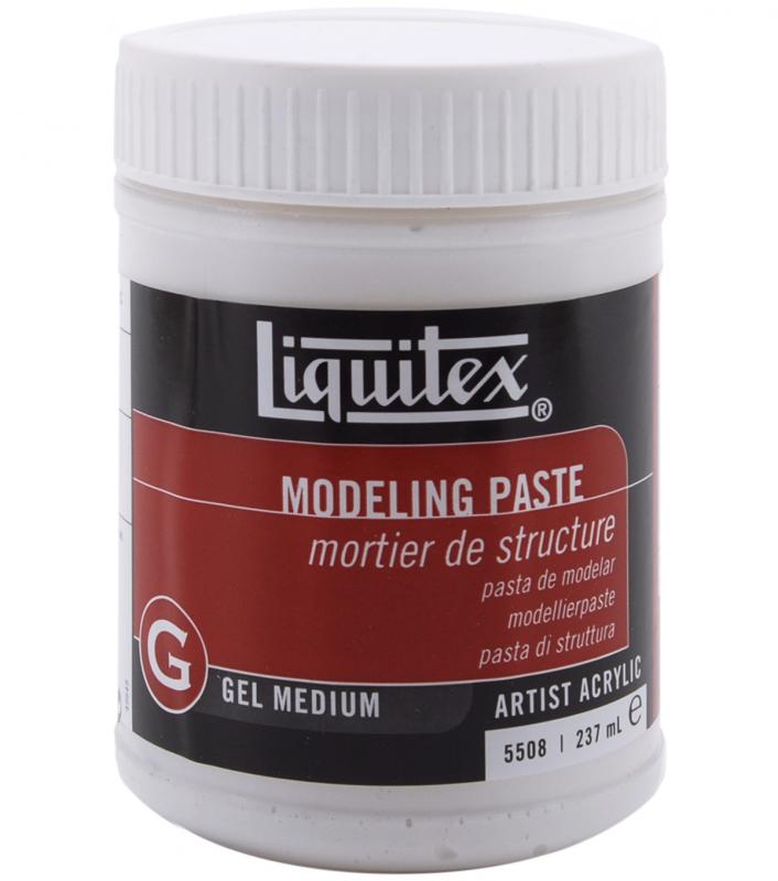
-
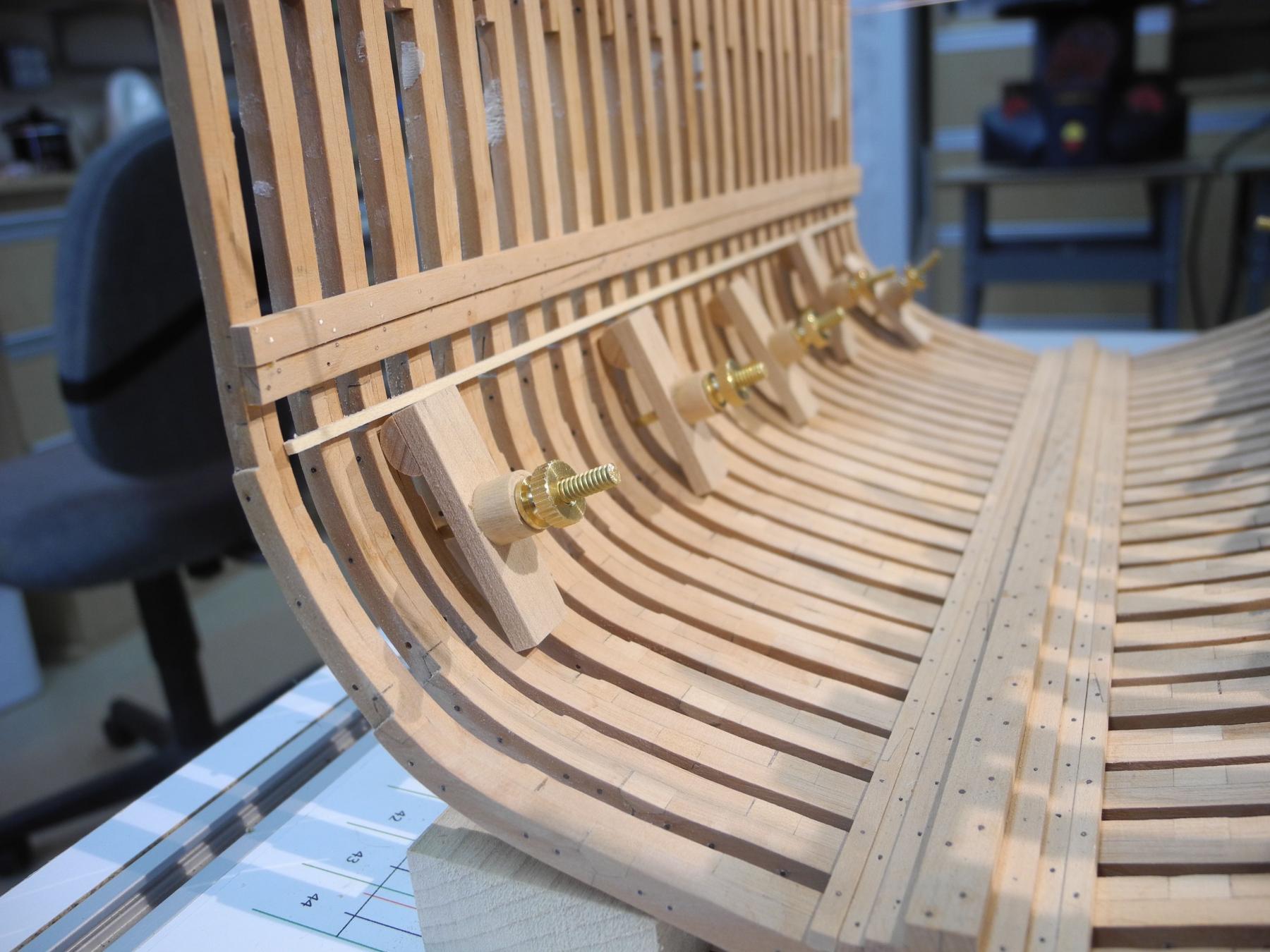
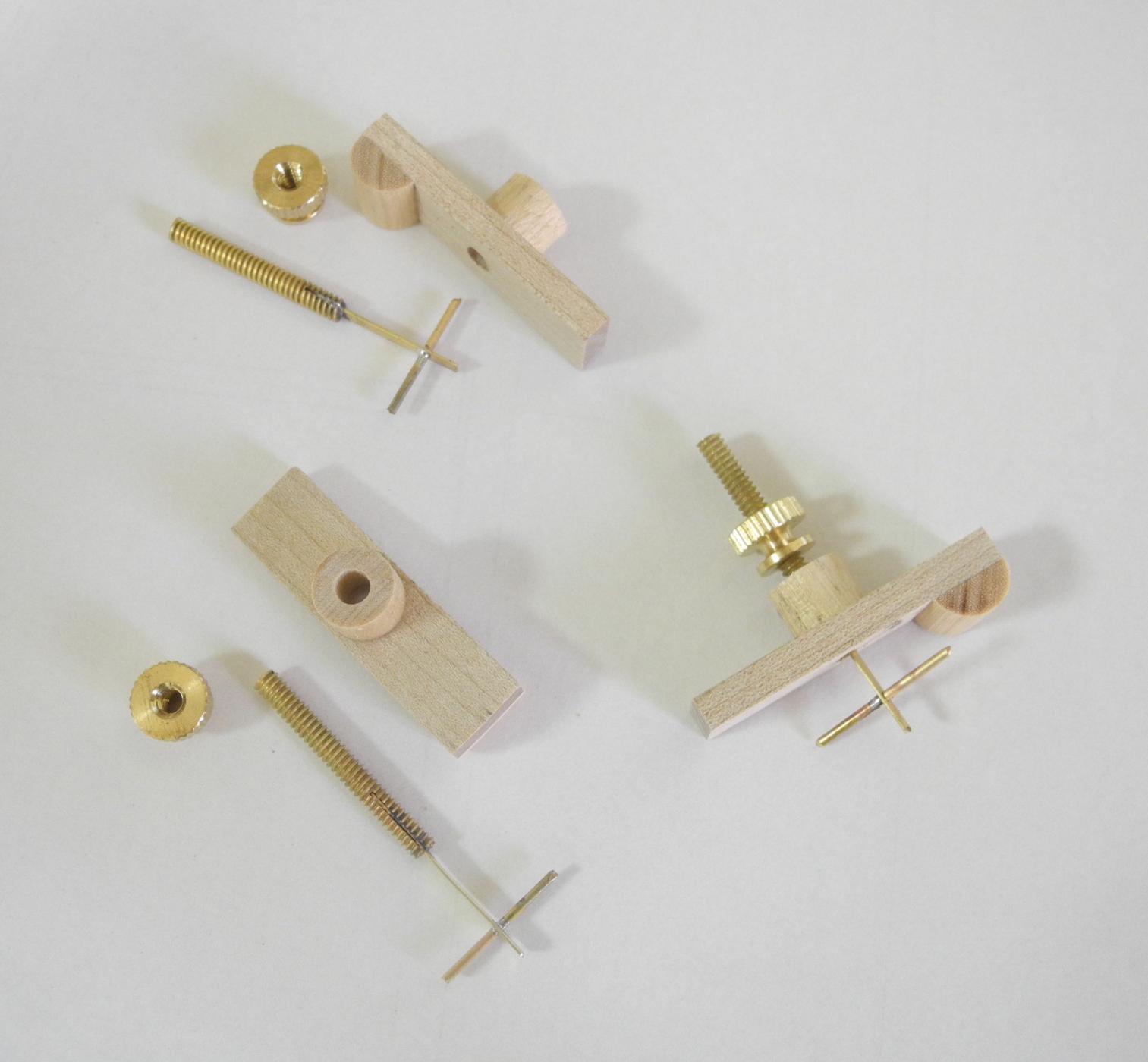
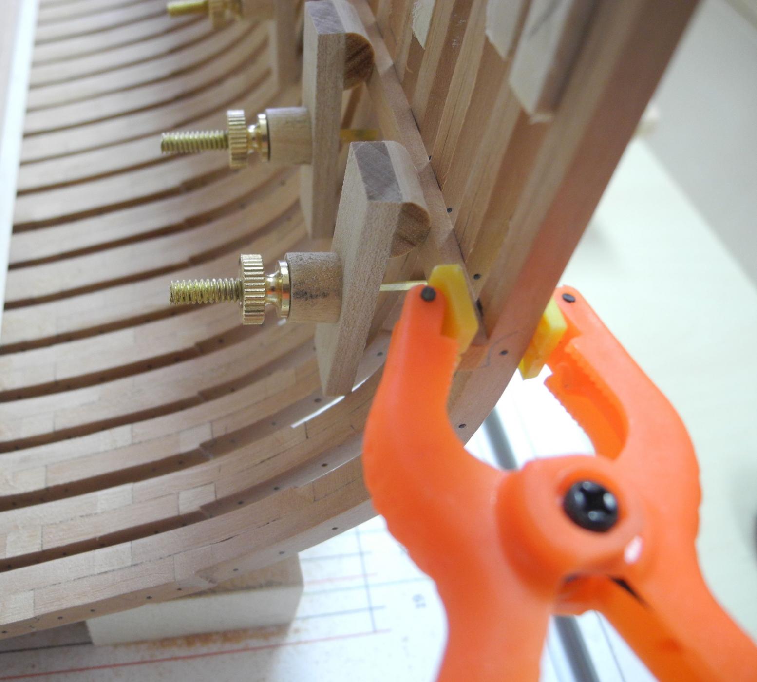
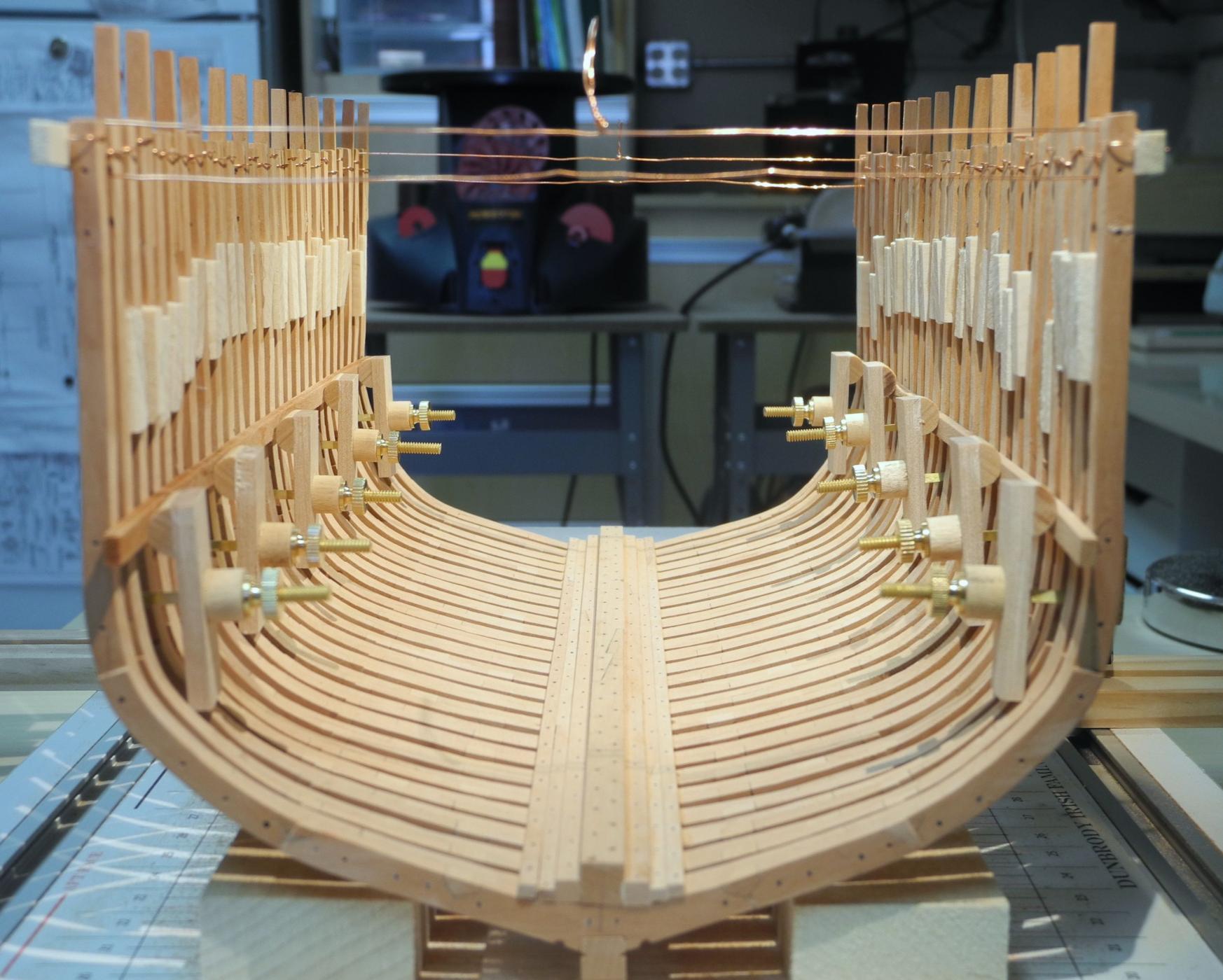
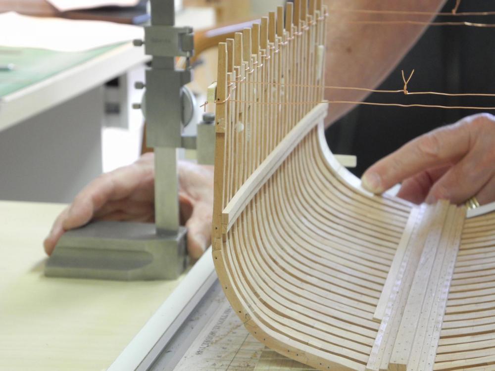
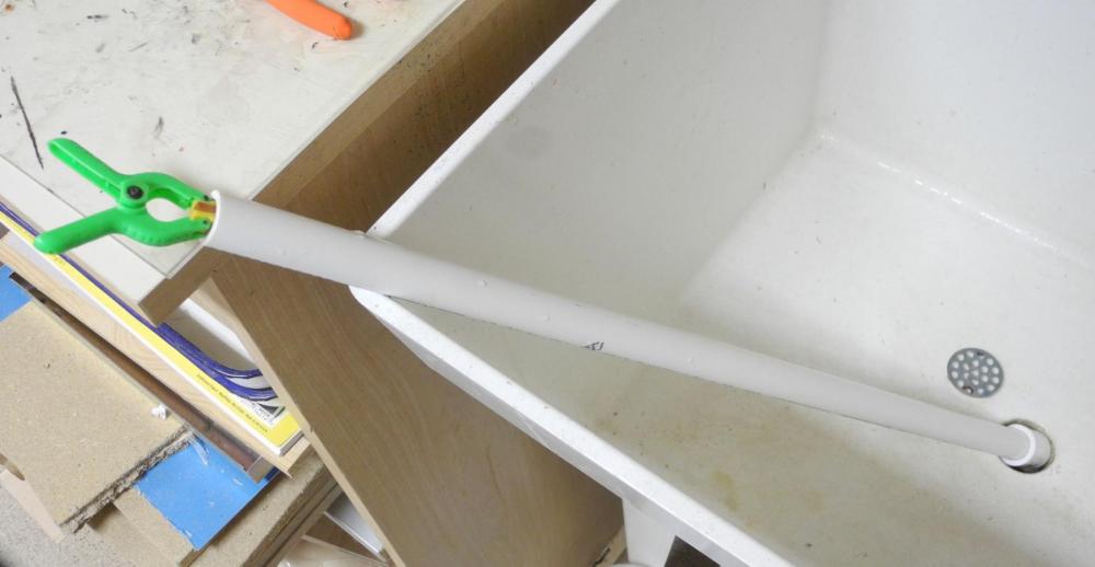
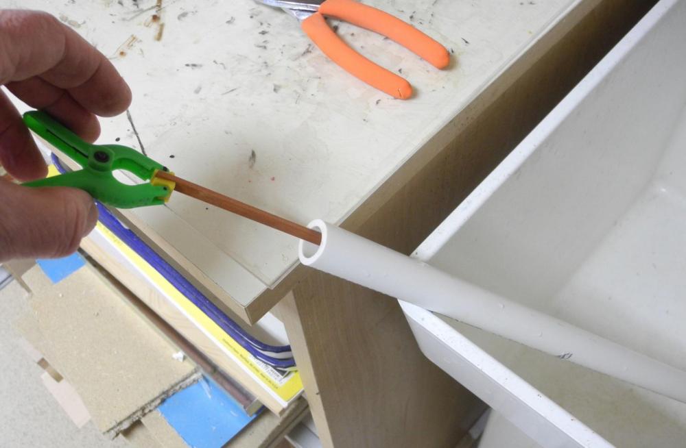
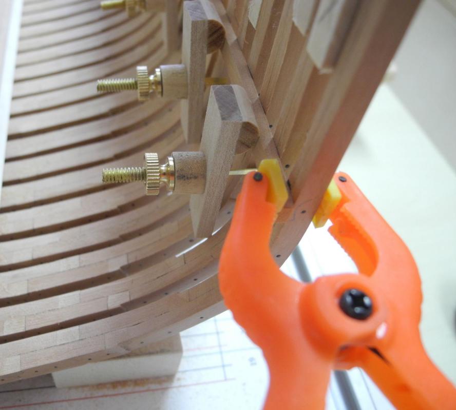
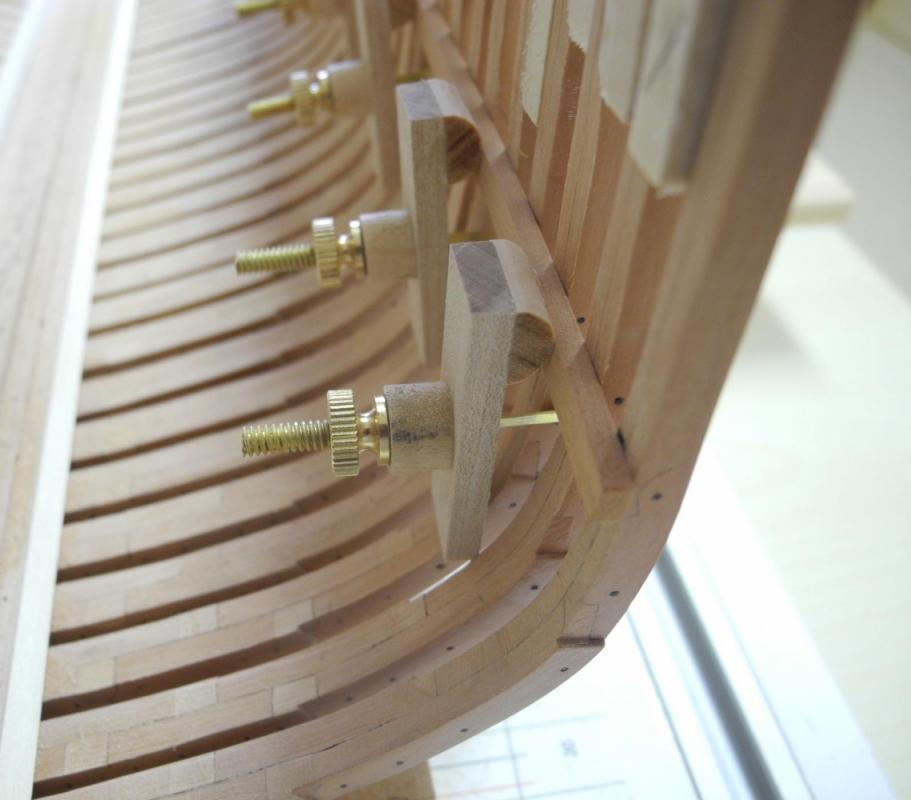
Part 17 – The Lower Accommodation Deck Clamp I had a medical procedure done on Tuesday, and as a result I was NOT PERMITTED to work in the shop (by my live-in nurse). While I was being good I decided to draft the planking for Dunbrody. I measured the cross-section provided by the plans and converted it into plank sizes for the model. I used these measurements to tune the Table of Scantlings that I had prepared during my planning exercise. This will prove useful when I’m milling the individual planks. Now I’m back to work in the shop, and I’m focusing on the lower deck clamp for the Accommodation Deck. Once this clamp is installed I’ll feel a lot more confident that the hull will retain its shape and the individual frames will stay perpendicular. As in all other longitudinal timbers, this deck clamp has a scarf. Since the clamp will also be bent to conform to the hull, I decided to use some ‘bolts’ to keep the scarf from separating during bending. I’ll probably use this approach for all of the major longitudinal timbers. I made an arm for the height gauge that would fit between the frames and was long enough to reach the inside of the hull from the work table – there isn’t enough room on the shipway surface for the base of the height gauge (another lesson learned). I will adjust all heights by adding the height of the shipway surface from the work table surface. Using measurements from the drawings I had prepared above, I marked the height of the Lower Clamp for the Accommodation deck. The internal surfaces of the frames needed to be faired to accept the clamp, so there was a lot of time spent in Checking the fairness from frame to frame Marking high spots and sanding the frames. When I was satisfied with the frames I soaked the clamp in boiling water. I use a length of PVC pipe with a cap on the end as a container, so I can fit a fairly long timber in my soaking pipe. Since the wood wants to float to the surface, I use a small spring clamp to weight it down. I had made some small planking clamps using the design EdT has in his Naiad Vol 1. Since I only had 6-32 knurled nuts I made the clamps somewhat smaller than Ed’s, and needed to solder 3/64 brass rod as the cross-pieces. These clamps work OK, but I intend to make larger clamps that will be able to use round toothpicks as the cross-pieces. When clamping the timber, I started by clamping the ends of the timber to the position markings using spring clamps, then installed the planking clamps at intervals. When the timber was fully clamped I removed the spring clamps. Both Lower Clamps for the Accommodation Deck are now temporarily in place for drying. I intend to install them over the weekend and hope to get some other key longitudinal timbers installed. It feels good to be back to work on Dunbrody after the short enforced break.


- 649 replies
-
- 20
-
-
- dunbrody
- famine ship
- (and 2 more)
-
Beautiful, Ed. The finish on the anchor is perfect. I don't recall you mentioning the TIVA cleaning solution before - what role does it play in the finish?
- 3,618 replies
-
- 4
-
-
- young america
- clipper
- (and 1 more)
-
Nice start, Brian. Hope to see it on Saturday.
-
ancre La Salamandre by tadheus - 1:24
Mahuna replied to tadheus's topic in - Build logs for subjects built 1751 - 1800
Very nicely done, Paul. I have the same kind of plane, and like it very much. -
Nice progress, Bob. I'll have to come up for a visit soon to take a close look.
- 348 replies
-
- 2
-
-
- pequot
- cable ship
- (and 1 more)