Mahuna
-
Posts
1,504 -
Joined
-
Last visited
Content Type
Profiles
Forums
Gallery
Events
Everything posted by Mahuna
-
 Hi Bill I quickly became frustrated with kits myself and started scratch building - don't plan to go back to kits. I'm looking forward to watching your progress.
 -
Hi Popeye - no competition, just displaying the models. I'm looking forward to seeing all the models.
- 649 replies
-
- 6
-

-
- dunbrody
- famine ship
- (and 2 more)
-
Beautiful, Ed. The realism in Young America continues to amaze me.
- 3,618 replies
-
- 6
-
-
- young america
- clipper
- (and 1 more)
-
Thanks Patrick. I'm looking forward to the conference. Thank you, Christian.
- 649 replies
-
- 4
-
-
- dunbrody
- famine ship
- (and 2 more)
-
Thanks Druxey. I'm disappointed you won't be there. Would have appreciated any observations you had to offer.
- 649 replies
-
- 4
-
-
- dunbrody
- famine ship
- (and 2 more)
-
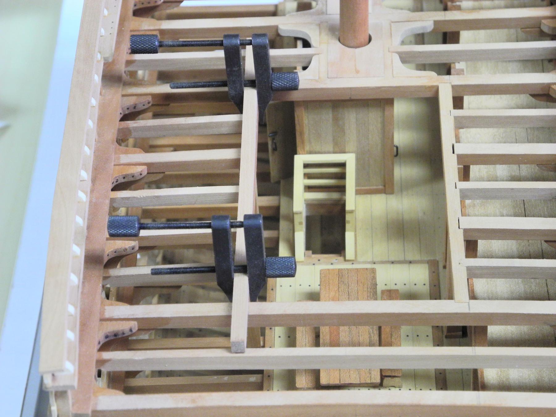
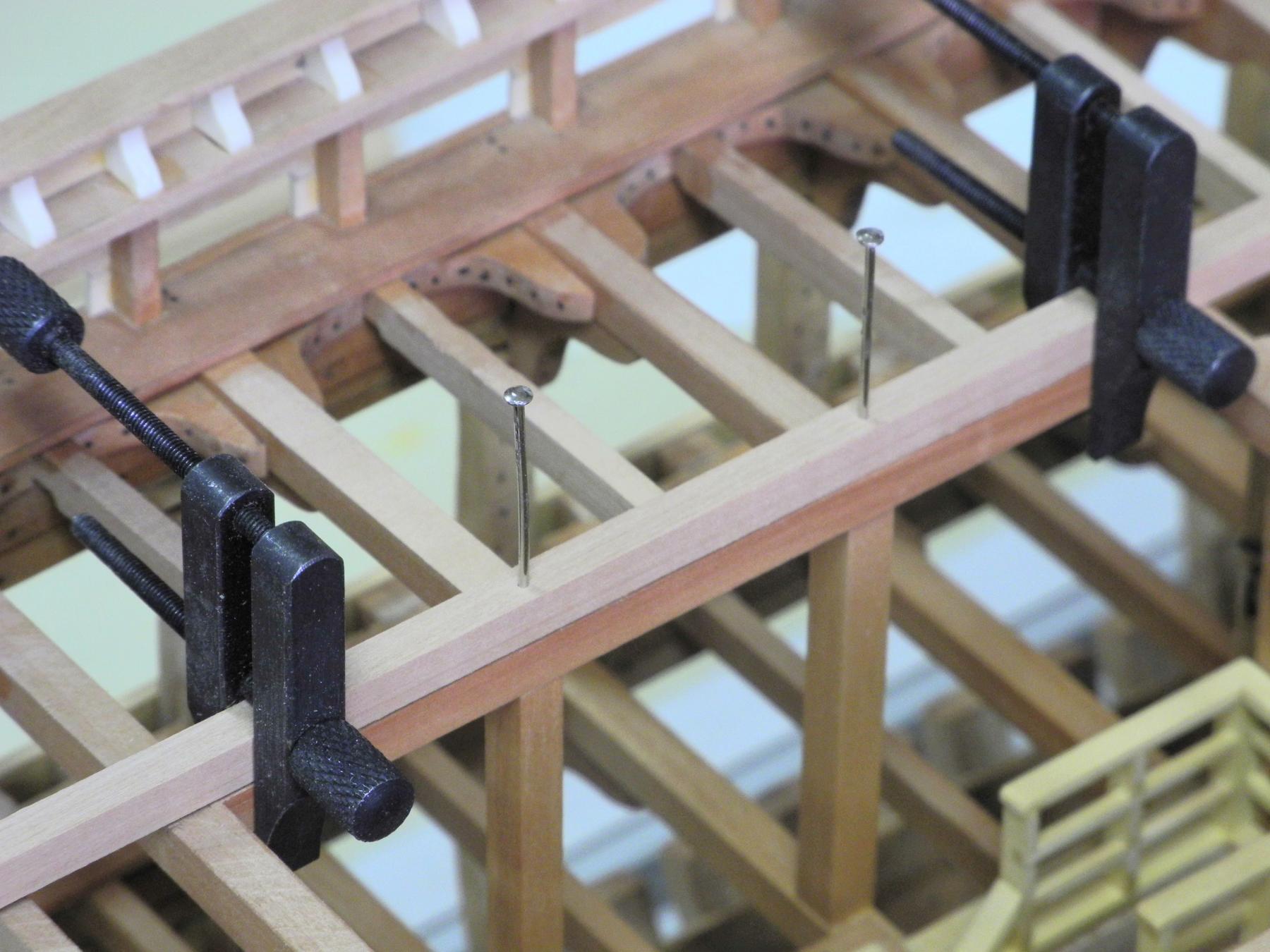
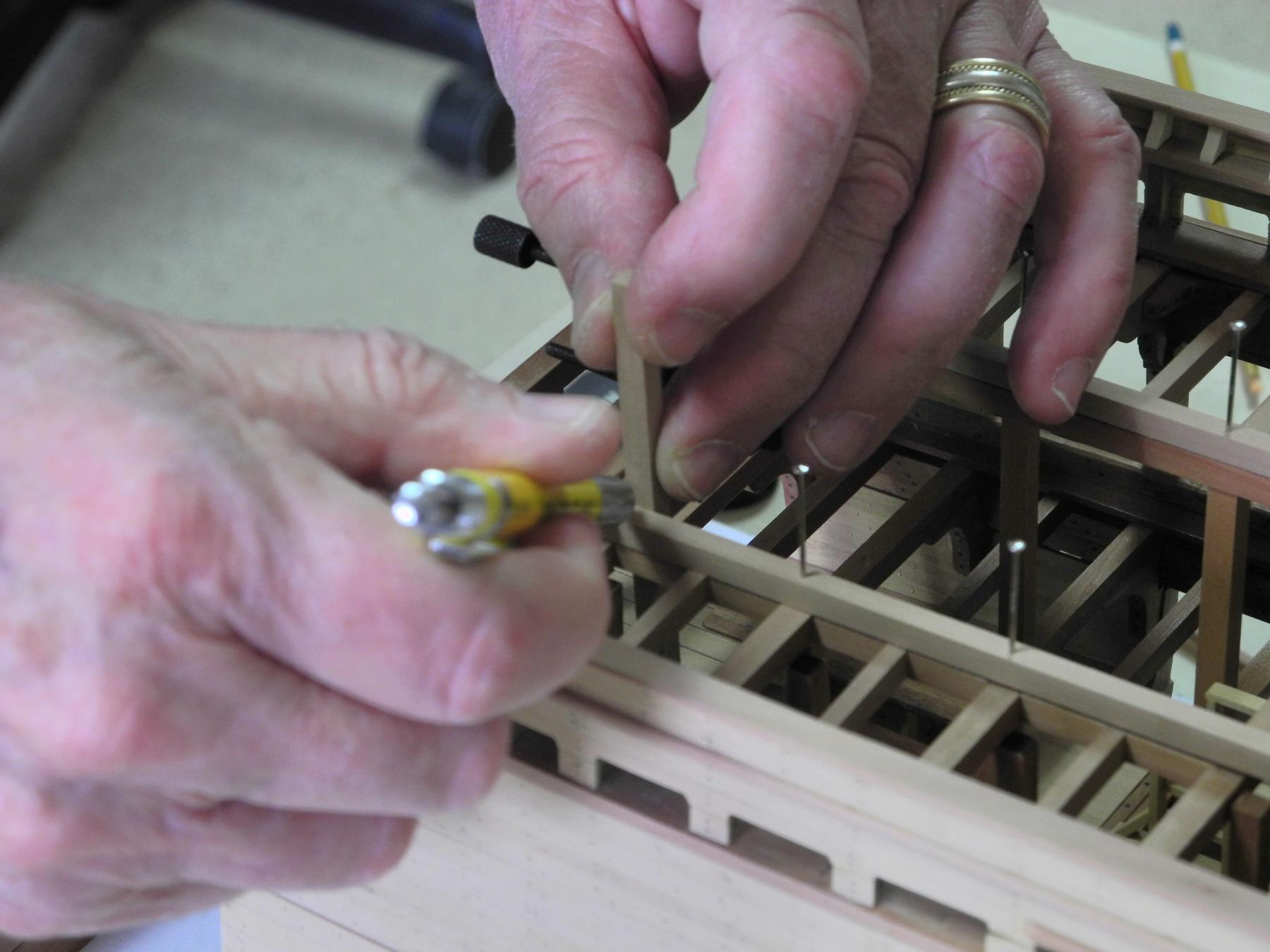
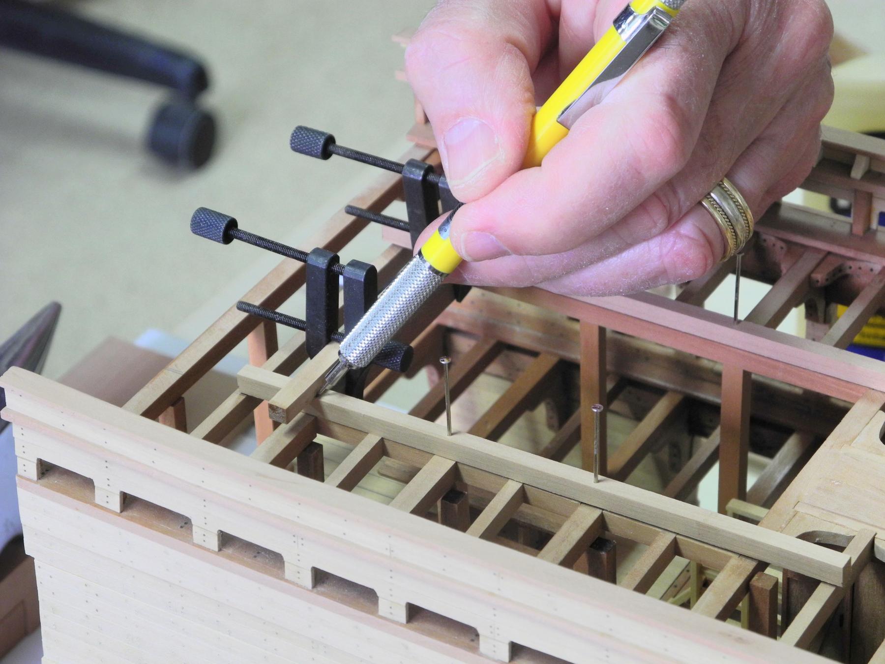
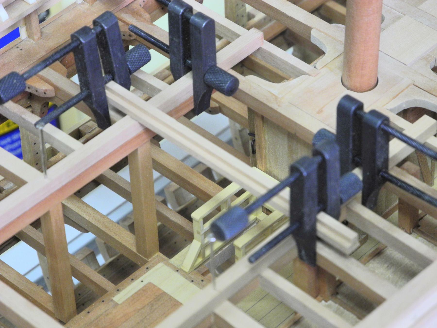
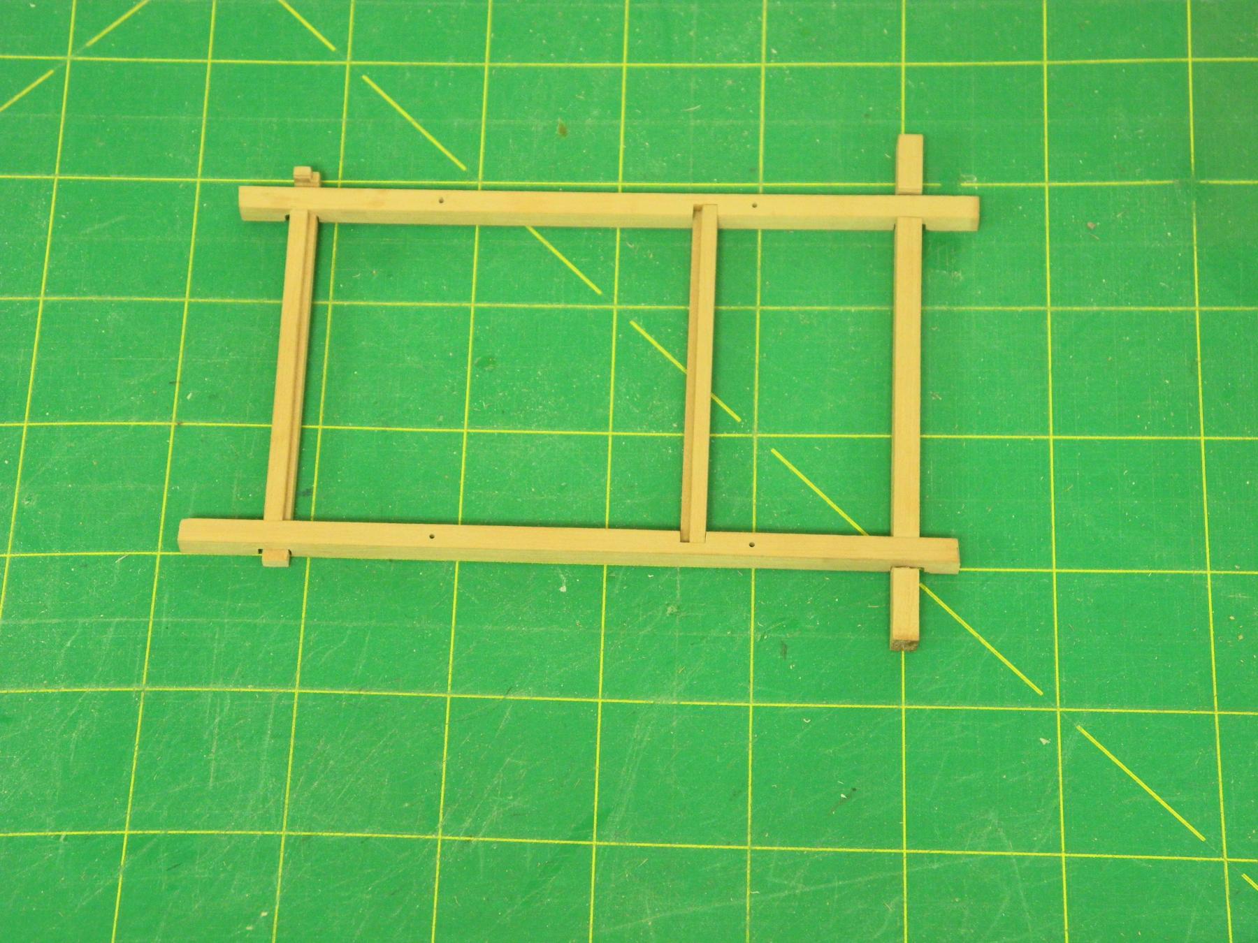
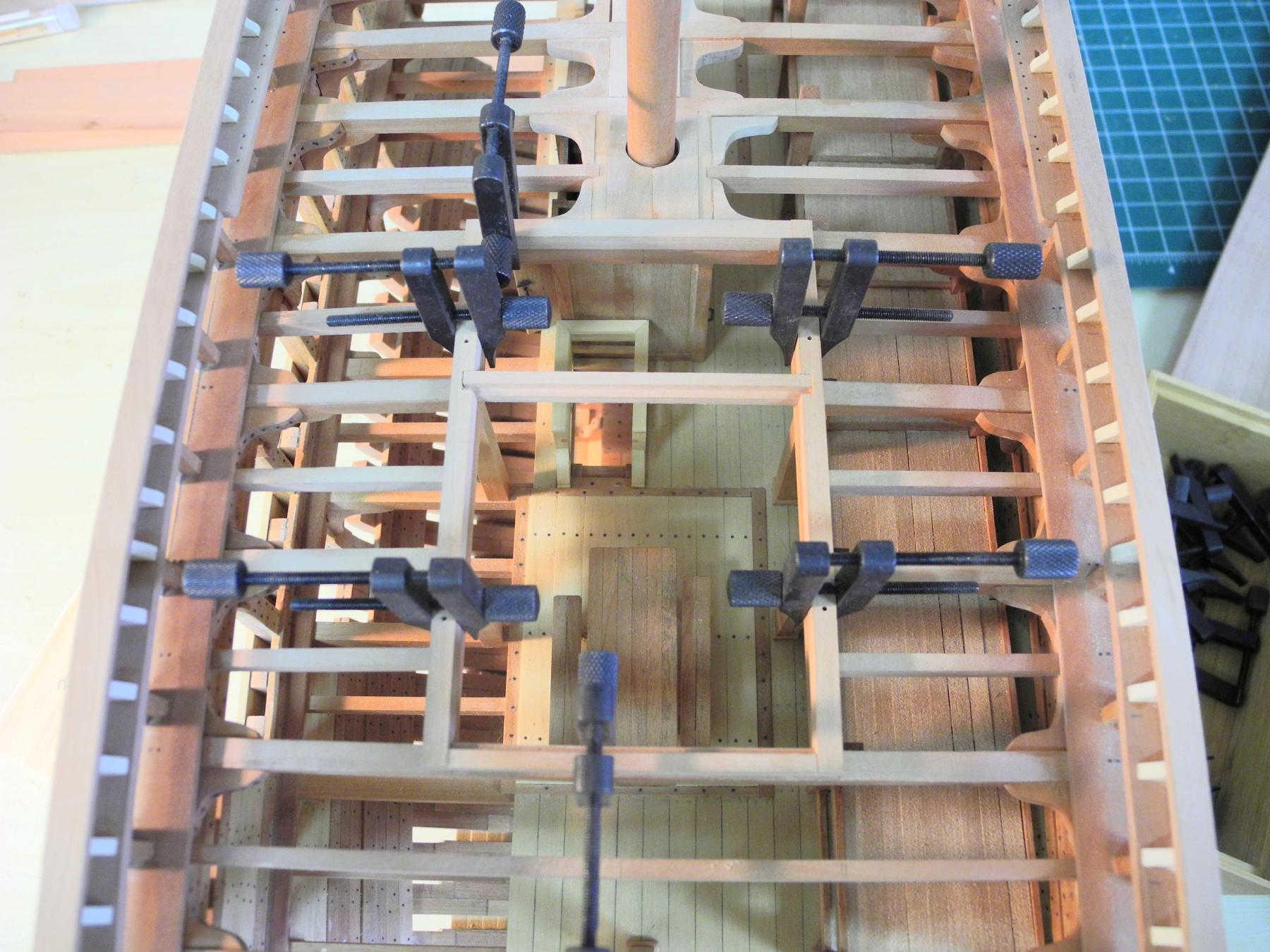
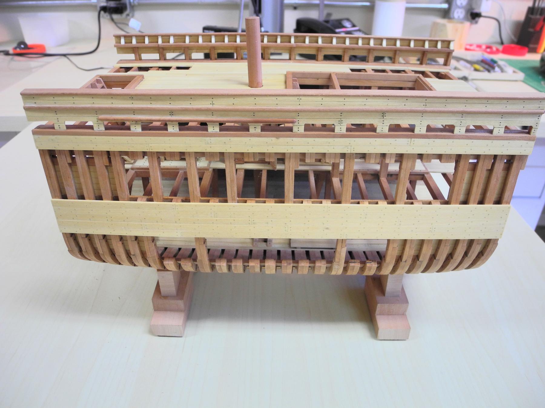
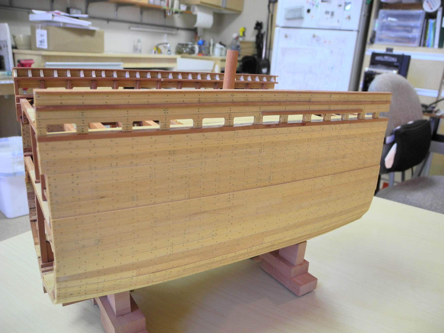
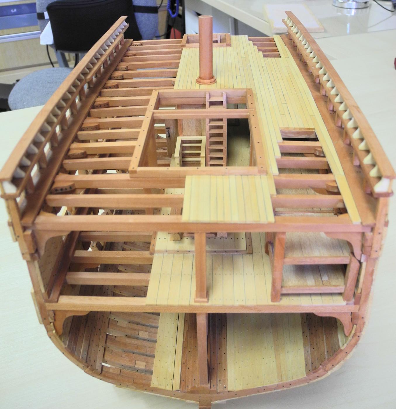
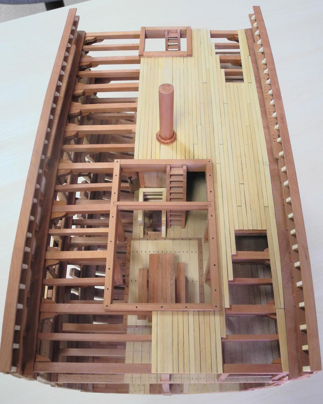
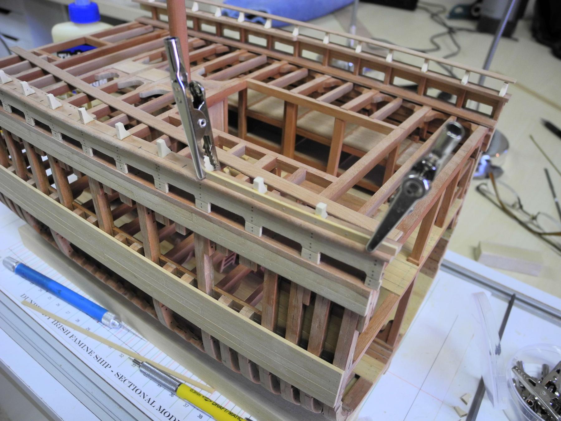
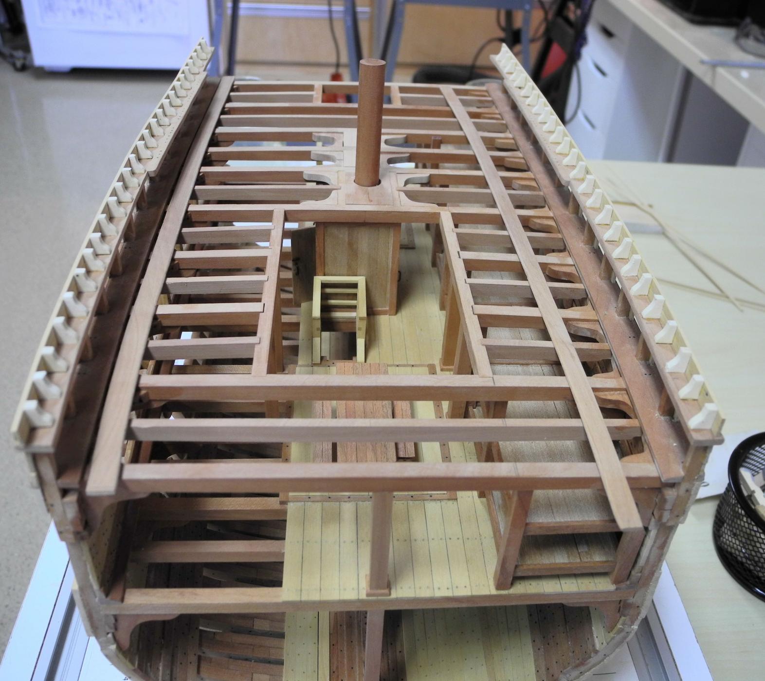
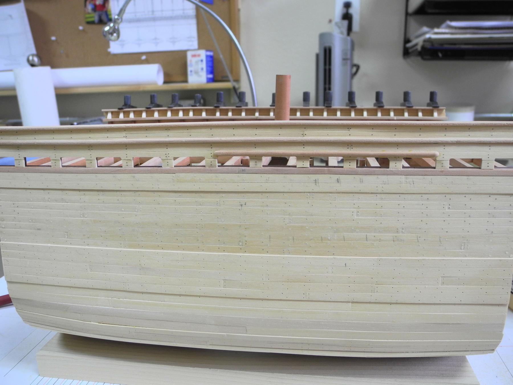
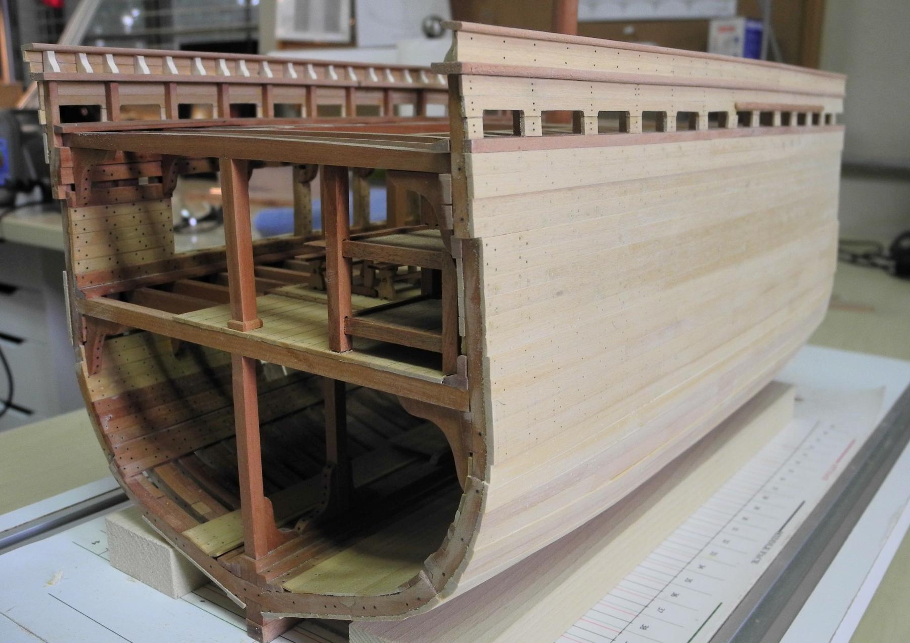
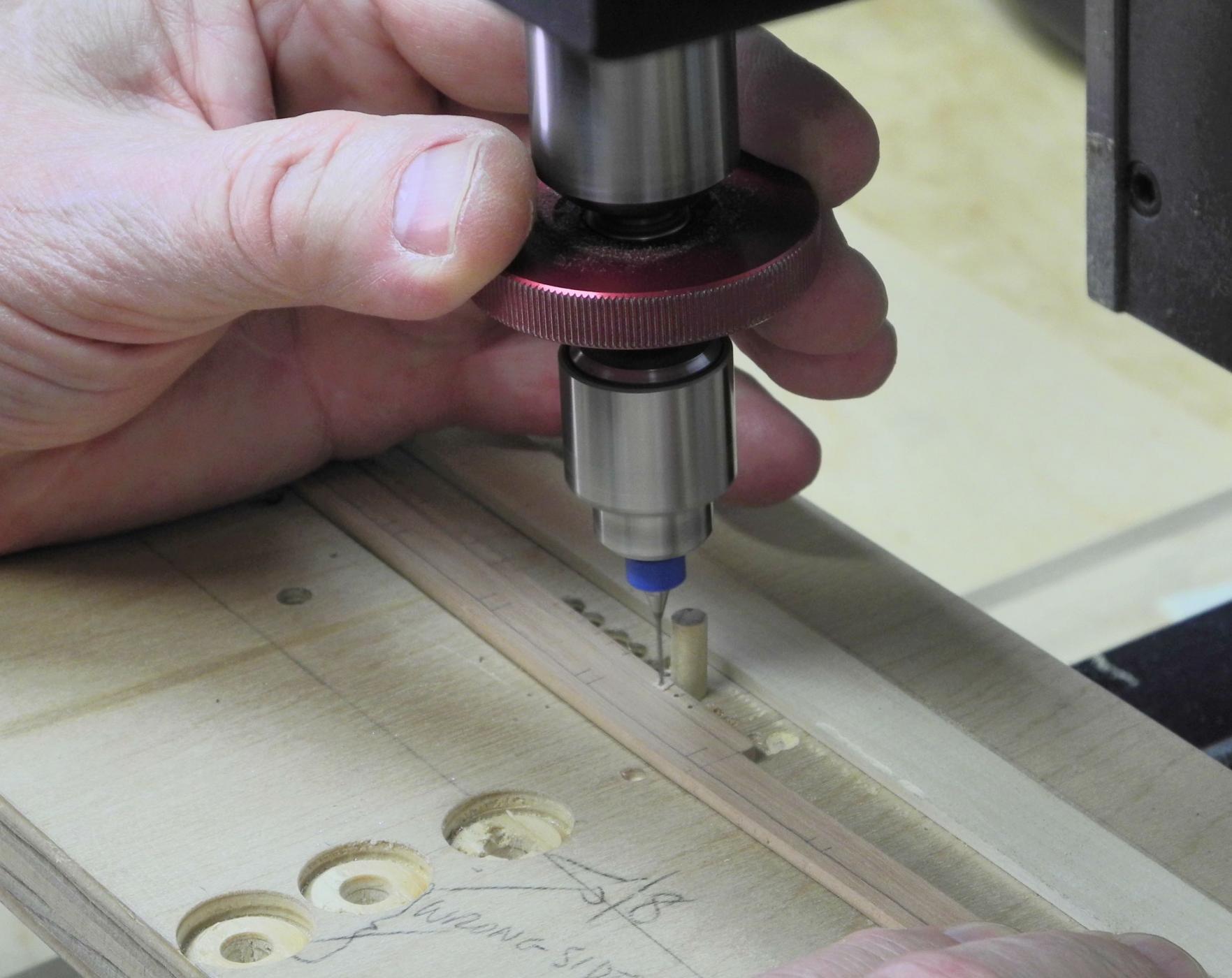
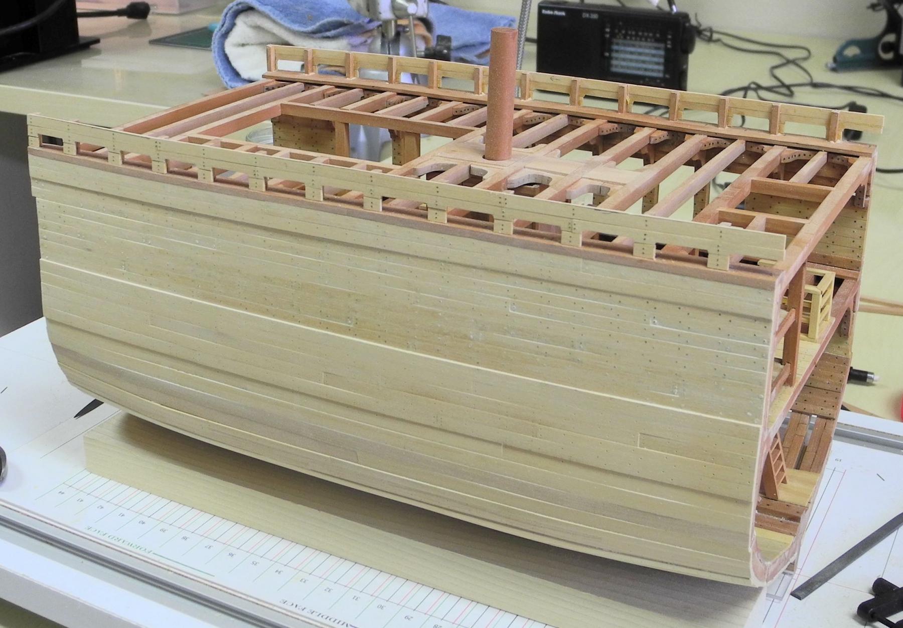
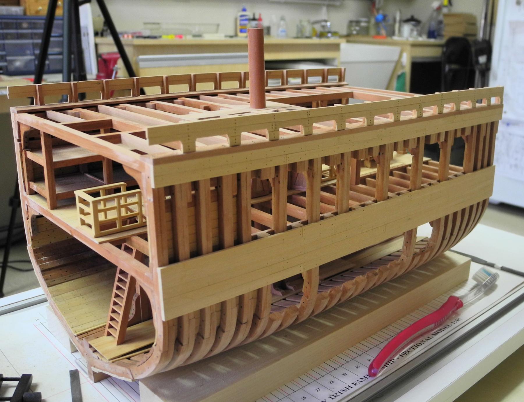
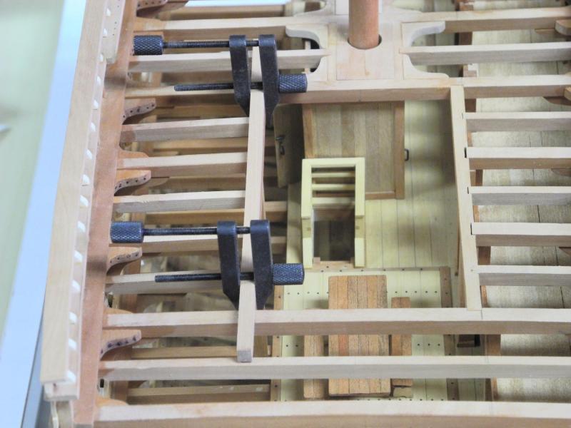
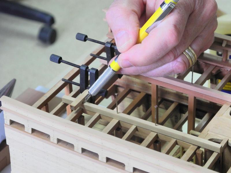
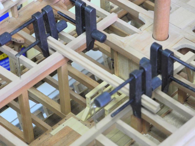
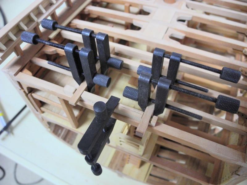
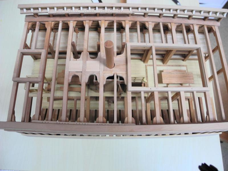
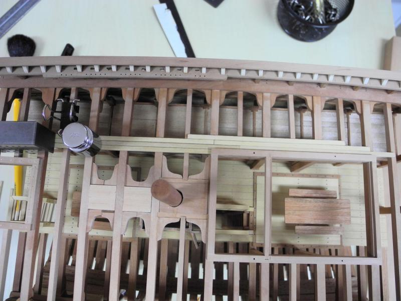
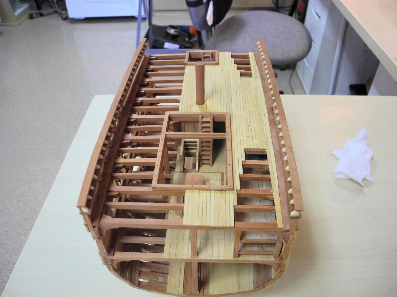
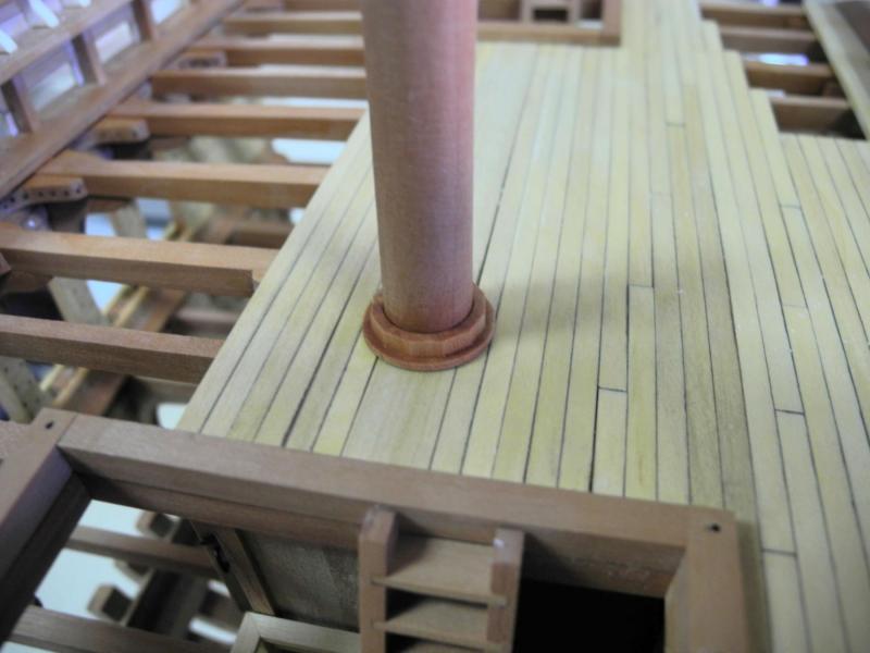
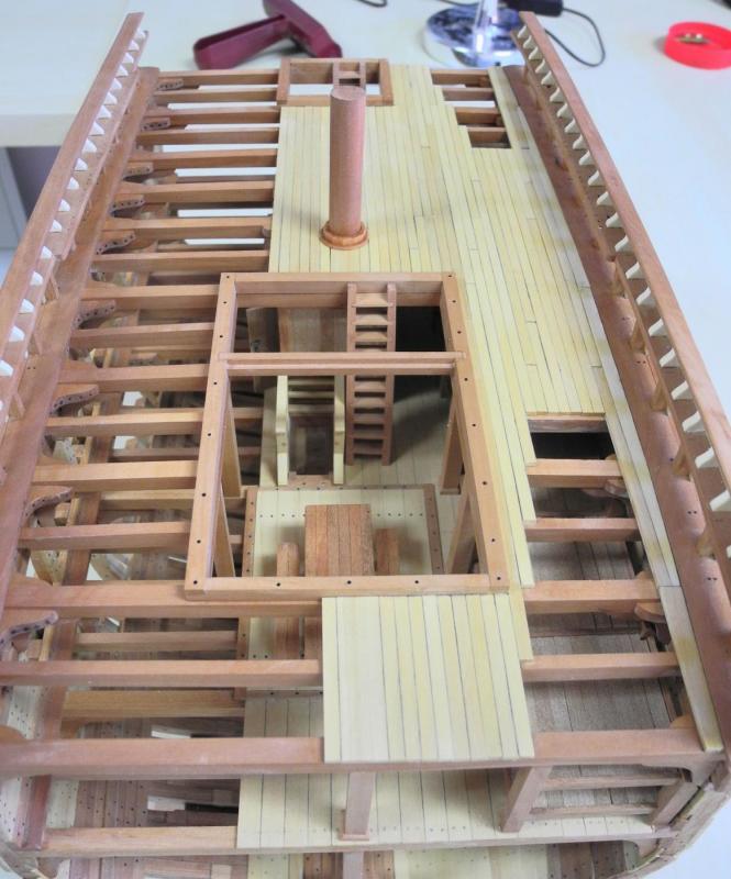
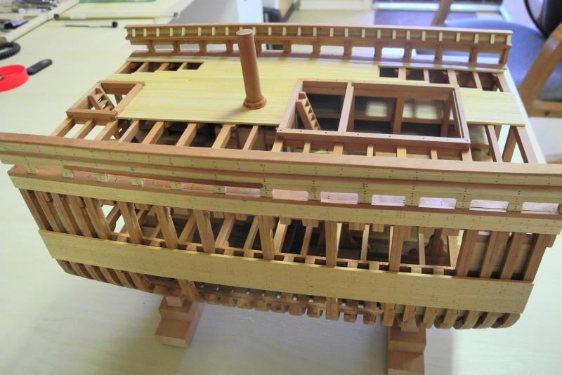
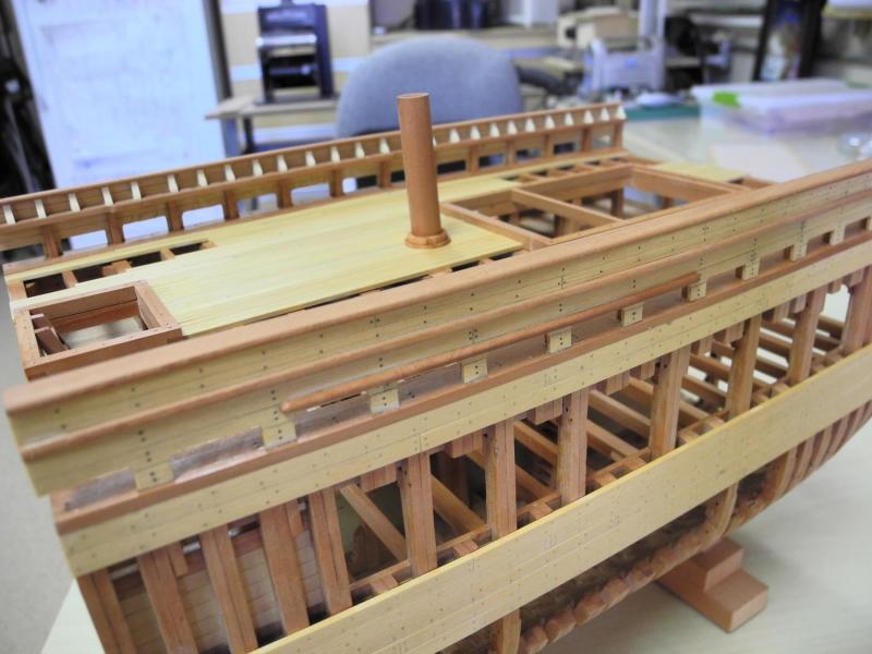
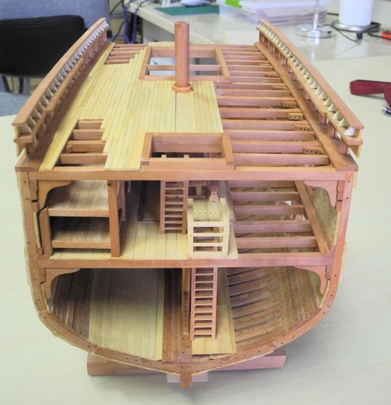
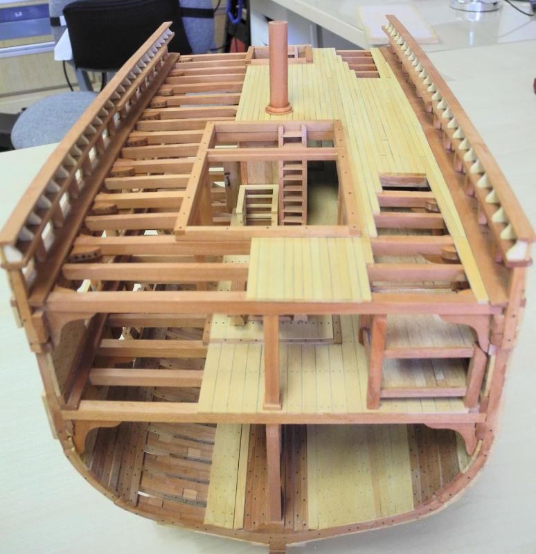
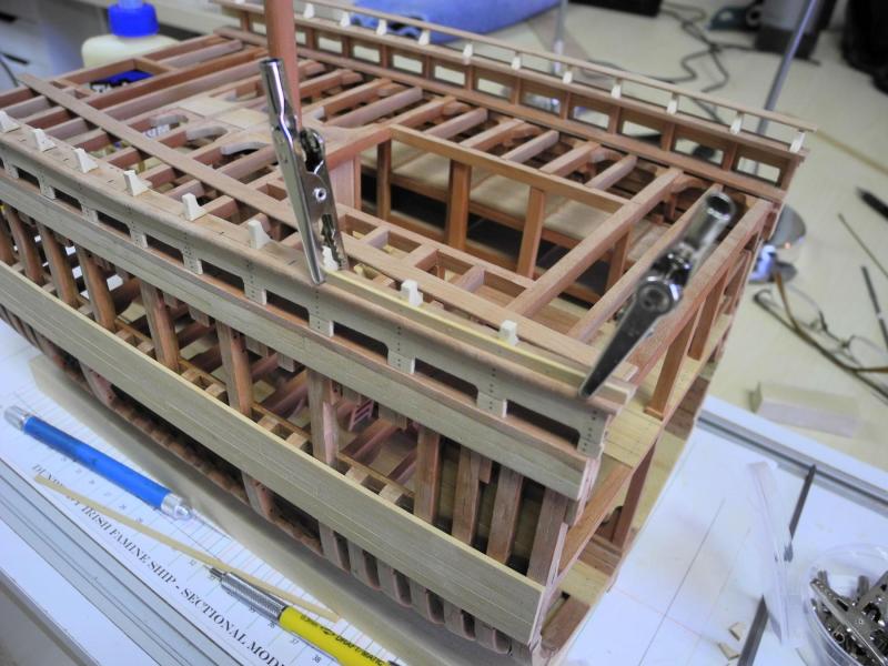
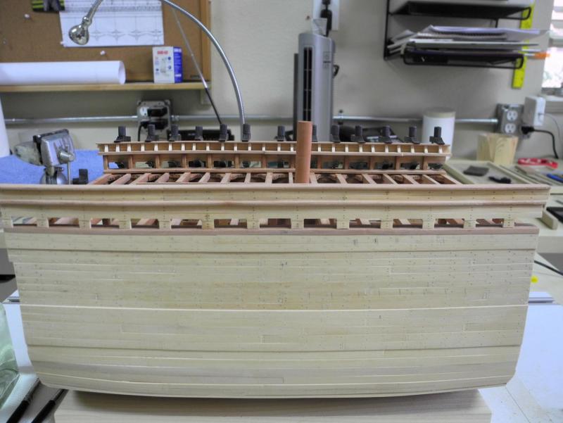
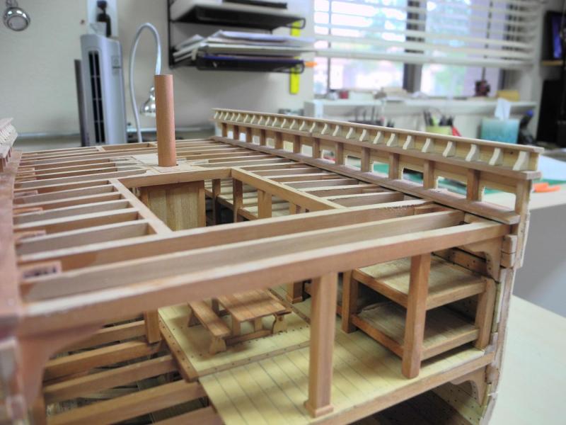
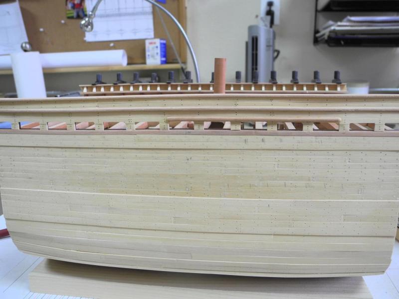
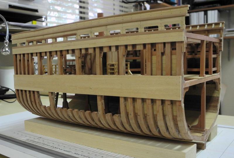
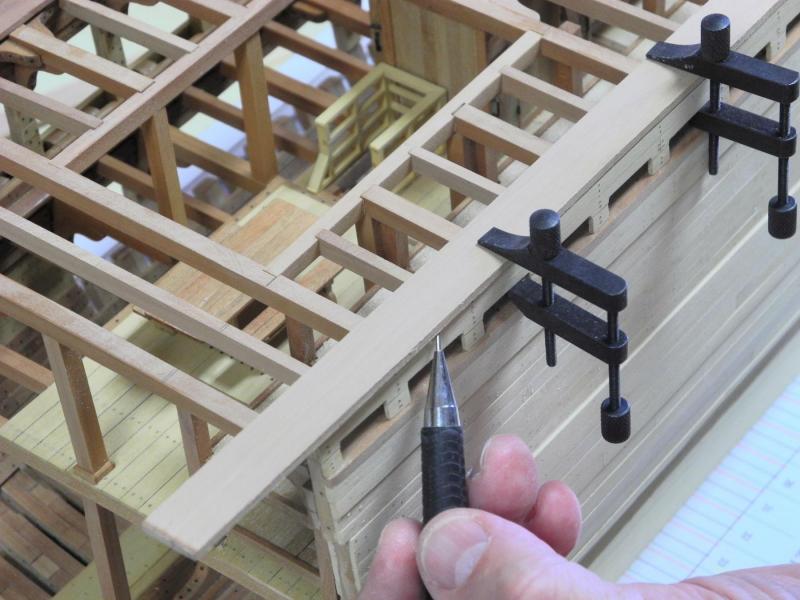
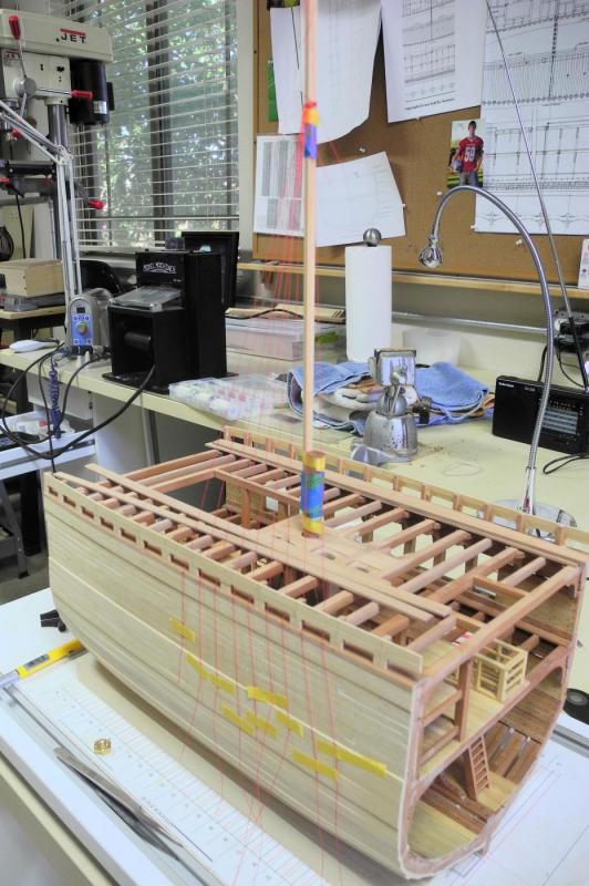
Part 47 – Main Deck Coamings, Ladders, etc. I’ll be bringing Dunbrody to the NRG Conference in San Diego later this week, so since the last post I’ve been focused on getting Dunbrody to a semi-completed state. The hatch coamings for the main deck were completed. Work began by clamping the coaming timbers (those that are longitudinal to the hatch) to the carlings underneath. Since both items were the same width, this kept the sides of the coamings flush with the carlings, so that there were no obstructions in the hatch opening. The coamings were temporarily pinned to the carlings to keep them in place. Marks were made on the coamings to indicate the position of the lap joints. Markings were also made on the ledge timbers (the hatch timbers that run athwart ship). These ledge timbers are so-called because they have a ledge for supporting the planks that would serve as hatch covers. These ledges were cut in on the milling machine set up as a router, as previously shown. The hatch timbers were assembled off the ship, with excess length left in place for trimming later. After the hatch frame was trimmed it was then glued and clamped in place. The same process was followed for the aft hatch, except that no ledges were cut since the aft hatch area will be fully occupied by the aft companionway. The forward of the two hatches (the main hatch) will also support a companionway towards the rear of that hatch. The aftmost ledge timber for the hatch itself can be seen on the following photo approximately two thirds behind the front of the hatch. Deck planking was begun after the hatch coamings were installed. Planking started at the port edge of the main hatch. The starboard side of the deck will be left open, following the approach that has been used throughout the model. Some planking was also left open in the area above the sleeping platforms, to allow better viewing of the Accommodation Deck structures. The main hatch will also be left open for this purpose. At the same time that deck planking was under way, ladders were made for the fore and aft companionways, for access to the Accommodation Deck from the Main Deck. The process for making ladders was explained in an earlier post. The hull planking was also treenailed during this work. Treenails were made from bamboo skewers, which were split down and pulled through a Byrnes drawplate. Finally, a mast coat with wedges was made, following the same process that was used on the Accommodation Deck. A finish of wipe-on poly was applied to the entire hull, main deck, and railings. Dunbrody has been mounted on its building board during the entire construction process. This building board is too large for display at NRG, and it is less secure than would be appropriate for a long drive from Phoenix to San Diego. The plans are for Dunbrody to sit on a base that is constructed as a traditional Launching Way, consisting of slipways and a launching cradle. Since this base has not yet been started, a temporary base was constructed. This new base was made from fairly thick timbers and has some padding for Dunbrody to sit on, so that the base can be used during any subsequent construction. So now Dunbrody is ready for the trip to NRG. There’s still a lot of work to do, once Dunbrody is back home: Companionways fore and aft; deadeyes and chainplates for the port side; a fife rail for the main mast; spider band on the main mast; belaying pins for the pin rails, fife rail, and spider band; bollards and mooring openings; and, finally, the permanent base as described above. In the meantime, thanks everyone for being part of this enjoyable build, and I hope to see some of you in San Diego.


- 649 replies
-
- 24
-
-
- dunbrody
- famine ship
- (and 2 more)
-
Looks great Bob. Can't wait to see it in real life in a couple of weeks.
- 348 replies
-
- 3
-
-
- pequot
- cable ship
- (and 1 more)
-
LOL! - thanks Brian I'm looking forward to seeing the Pequot. Thanks Popeye.
- 649 replies
-
- 7
-
-
- dunbrody
- famine ship
- (and 2 more)
-
Thanks Patrick! I do like the look of the little topgallant stanchions - they finish off the railings nicely.
- 649 replies
-
- 5
-
-
- dunbrody
- famine ship
- (and 2 more)
-
Hi Brian: A while back you told me about the advanced uploader and I tried it. I was able to use it successfully for a couple of weeks, but then it stopped working and I had to go back to the basic uploader - one photo at a time. I'm a Mac user and prefer to use Safari. I've tried updating Flash in Safari several times, to no avail. Today I decided to try Firefox from Mazilla and the advanced uploader worked fine. If anyone reading this topic is also a Mac user but is able to use the advanced uploader in Safari I'd like to hear from you so I can learn if there are any other settings needed in Safari for the advanced uploader to work.
-
Great work, as usual, Ed. Hand- shaping the whisker booms must have been difficult. I'd love to see any holding device you used while working on the booms.
- 3,618 replies
-
- 4
-
-
- young america
- clipper
- (and 1 more)
-
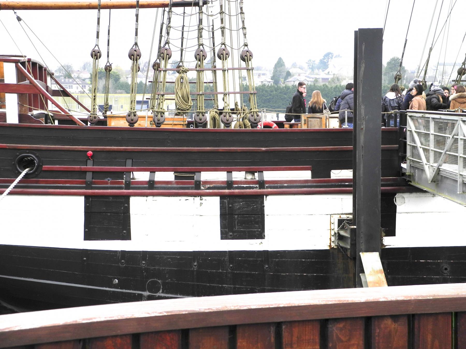
Thanks Bob - yes, I'm really pleased with the look now. After the NRG Conference I'll try to get up your way and I'll bring Dunbrody. Thanks Ed. Without the photos I don't think my Dunbrody model would be very interesting. The plans don't show the detail that's on the replica ship, so the photos have been a big help. I only wish I had known a little more about ships and ship modeling when I toured Dunbrody. There are a lot more photos I would have taken. Thank you, Albert.
- 649 replies
-
- 7
-
-
- dunbrody
- famine ship
- (and 2 more)
-
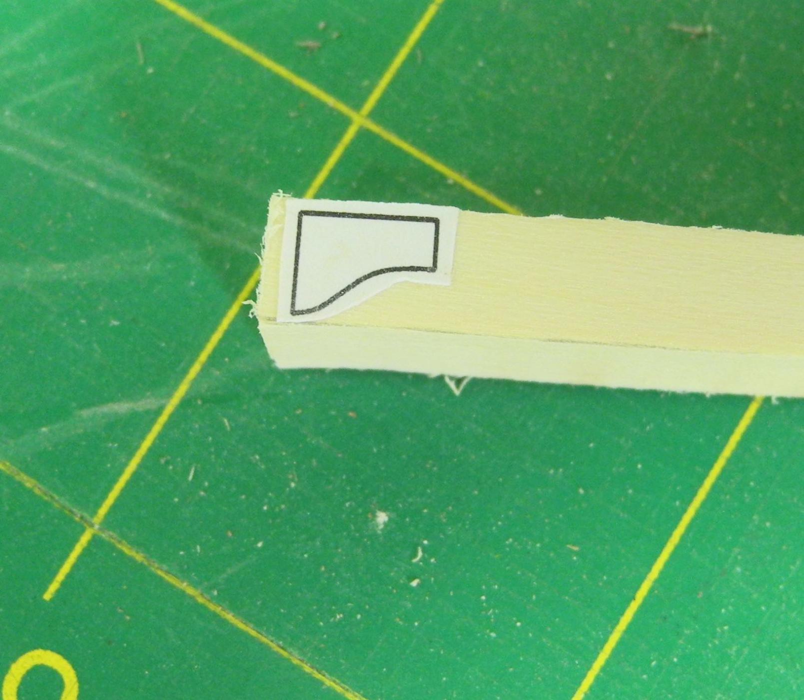
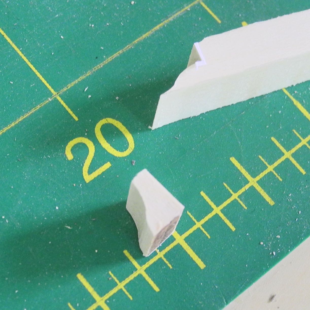
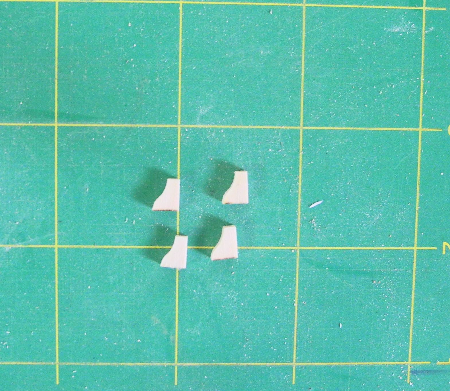
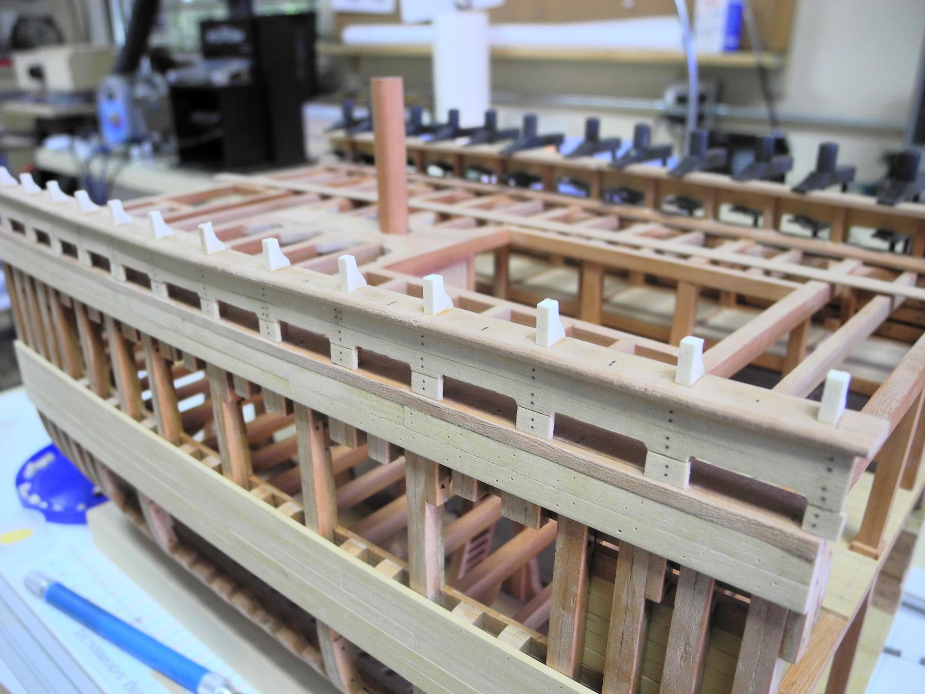
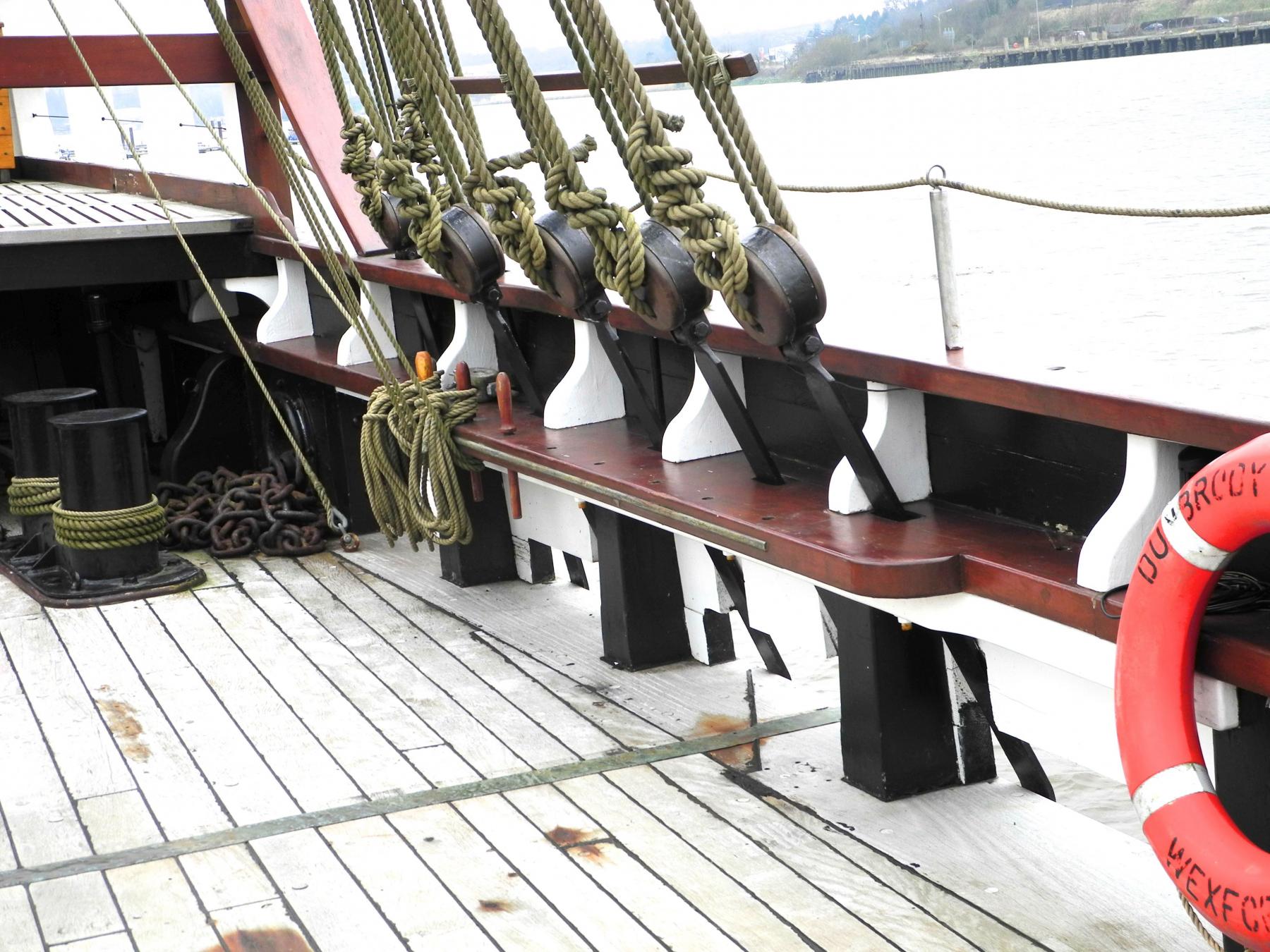
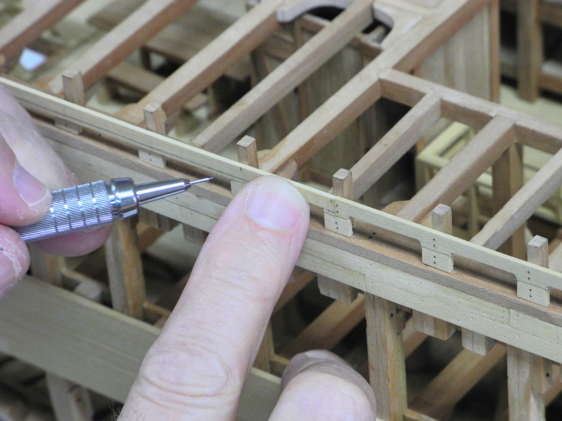
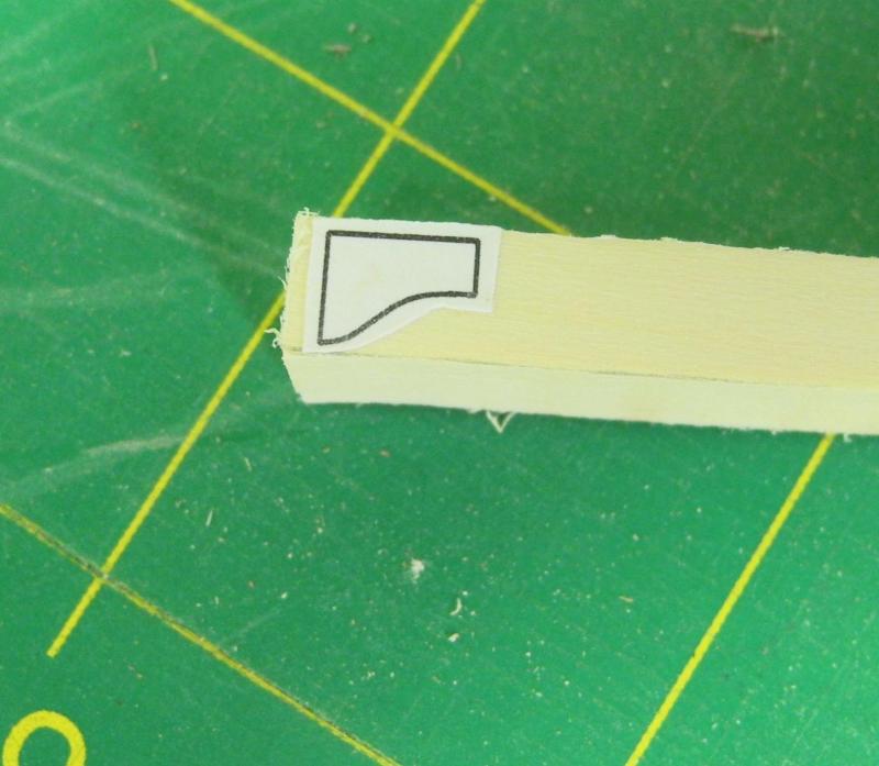
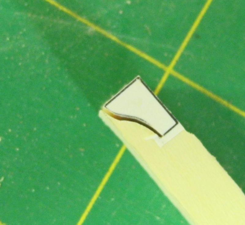
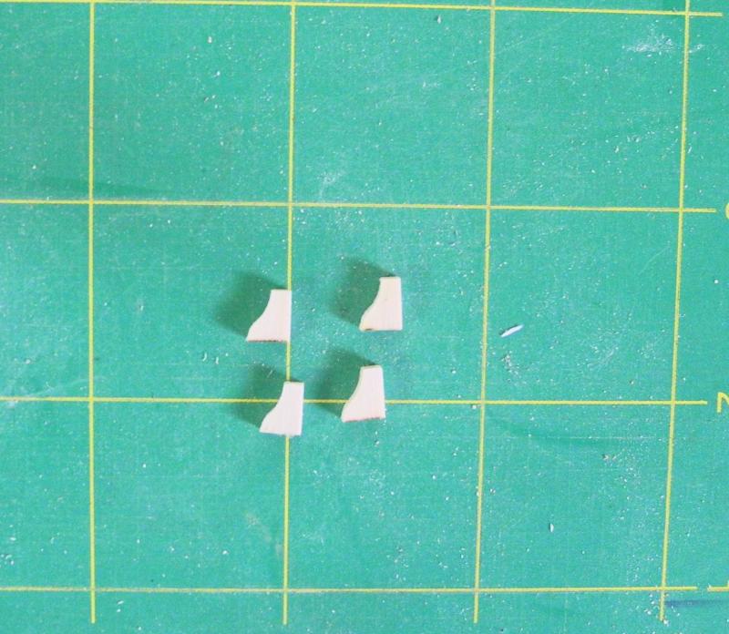
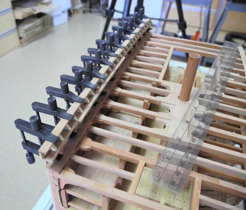
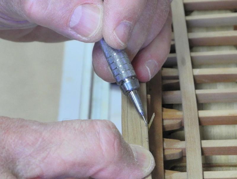
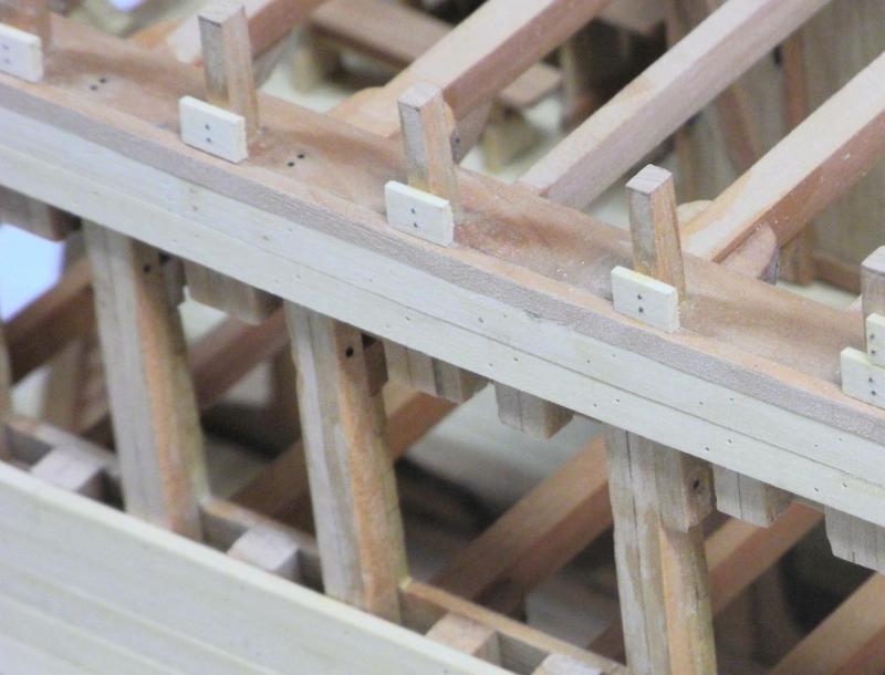
Part 46 – TopGallant Rails The topgallant rails are 3 inches thick (1/16 on the model). I decided to also make them from a single piece of stock for simplicity. The curve of these rails was taken from the main rails before those rails were installed. The topgallant rails are supported by a large number of oddly shaped stanchions. These stanchions appear to be above each of the main stanchions, plus additional topgallant stanchions between these. I think these topgallant stanchions will be a striking part of the model, so I wanted them to stand out. On the replica ship these stanchions are painted white, so I decided to use holly for them. Since there are so many stanchions (52 in all) I used 4 pieces of holly glued together with ambroid glue, so that 4 were made at a time. A piece that was slightly larger than the width of a stanchion was parted off, and a drawing of a stanchion was glued to it. The bottom and the straight side were shaped using the disk sander, and the curved side was cut on the scroll saw. These stanchions are so small there was no opportunity to do any final shaping, so accuracy in cutting the curved side was critical. The set of stanchions was then parted off, leaving a little height on the stanchions for shaping later. The set of 4 stanchions were then immersed in acetone (in a closed container) for a few minutes to dissolve the glue. This process only took a couple of hours, since making 4 stanchions at a time reduced the amount of effort involved. Once all of the stanchions were manufactured, installation could begin. A line had been drawn on the edge of the main rail to indicate the location of the outside edge of each stanchion. The topgallant stanchions that would be located over the main stanchions were installed first. Since there was no opportunity to clamp or pin these stanchions due to their small size, a different gluing technique was used. Glue was painted on each surface with a fine brush, and was left to set up for a few moments. The stanchions were then pressed in place and left to dry. This approach made the PVA glue act like a contact cement, and the stanchions were securely held in place. Once the glue had dried sufficiently the bulwark planks were installed. As with the other bulwark planks, these were first marked, pre-drilled, and copper simulated bolts were installed prior to installing the planks. Alligator clips were used to clamp these planks in place. None of the stanchions came loose during this clamping – proving the strength of the bond described above. After all of the planking had been installed the remaining stanchions were then installed by gluing them to the main rail and to the bulwark planking. The tops of the stanchions had been left slightly oversized. This was reduced to the final height by filing the stanchion down to the top of the bulwark planks. The topgallant rails were then installed by gluing to the top of the stanchions and the top edge of the bulwark planks. The replica ship has a piece of molding located above the scuppers in the area of the chainplates. This molding was created by parting off the shaped edge of a piece of extra main rail stock, and was glued in place. The railings are now complete. I especially like the effect on the unfinished starboard side – it no longer looks as rough as it has. Now that the rails are finished I can turn to the details on the main deck itself. The hatch coamings and planking need to be done before the chainplates and deadeyes can be installed. Thanks everyone!


- 649 replies
-
- 26
-
-
- dunbrody
- famine ship
- (and 2 more)
-
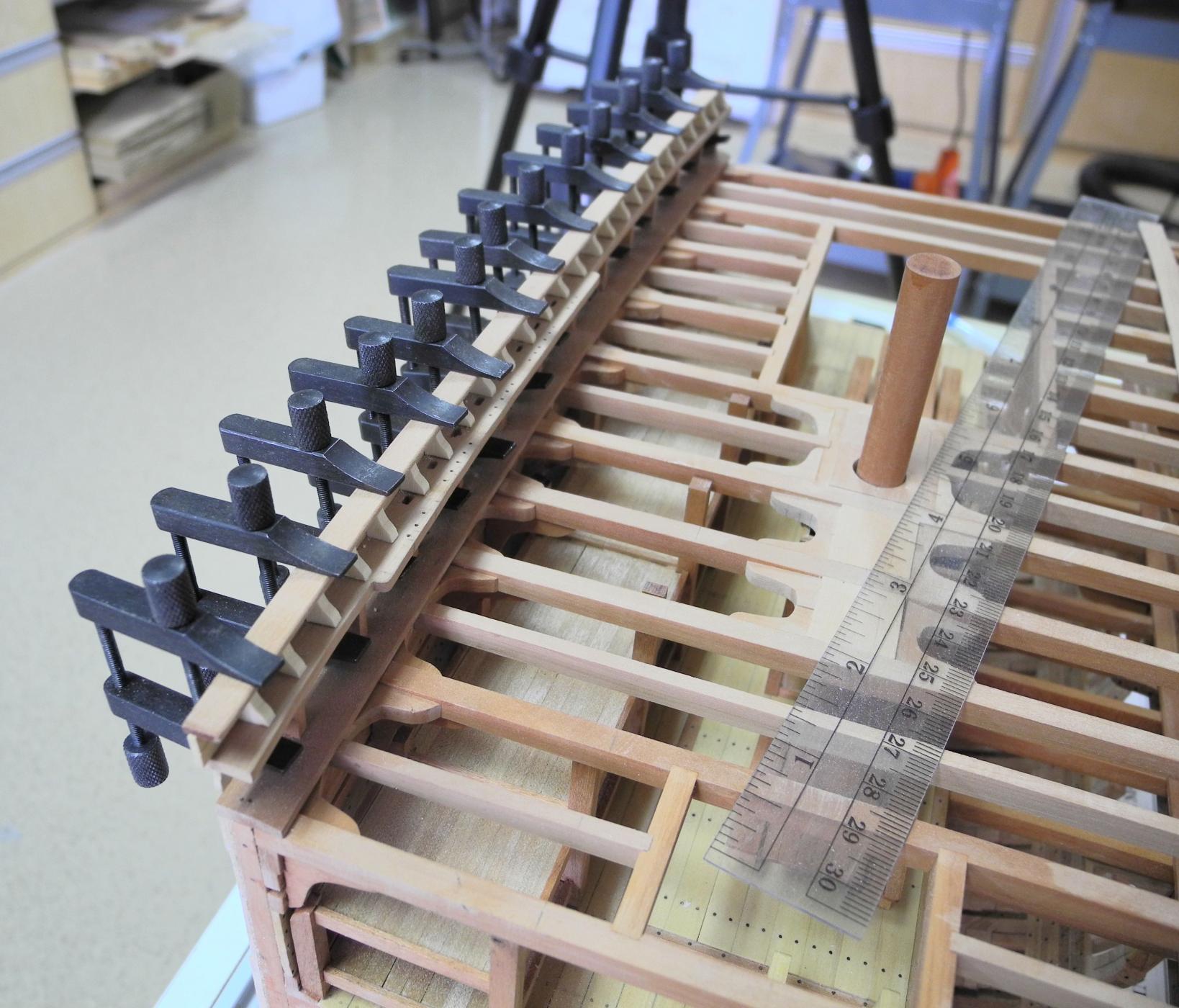
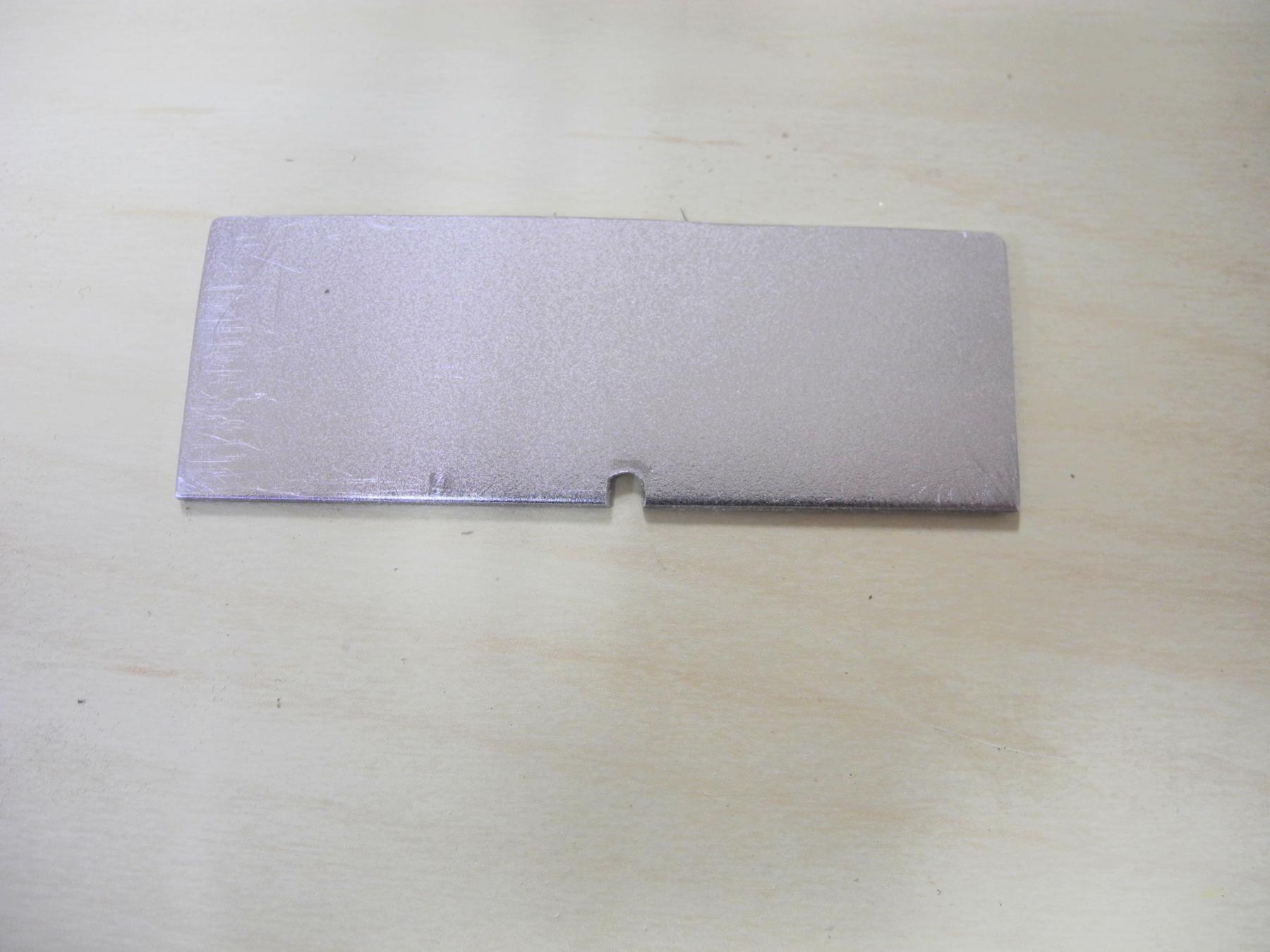
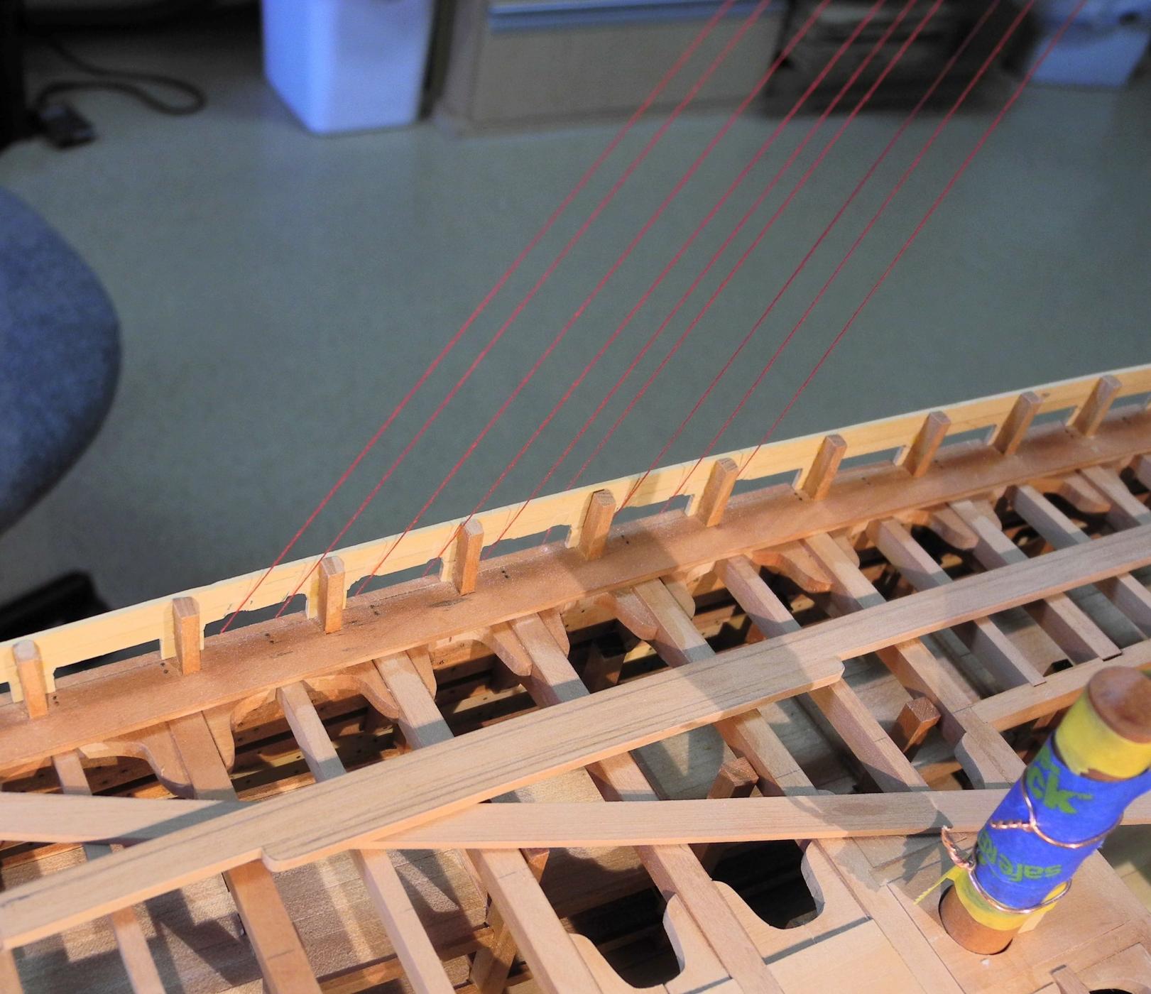
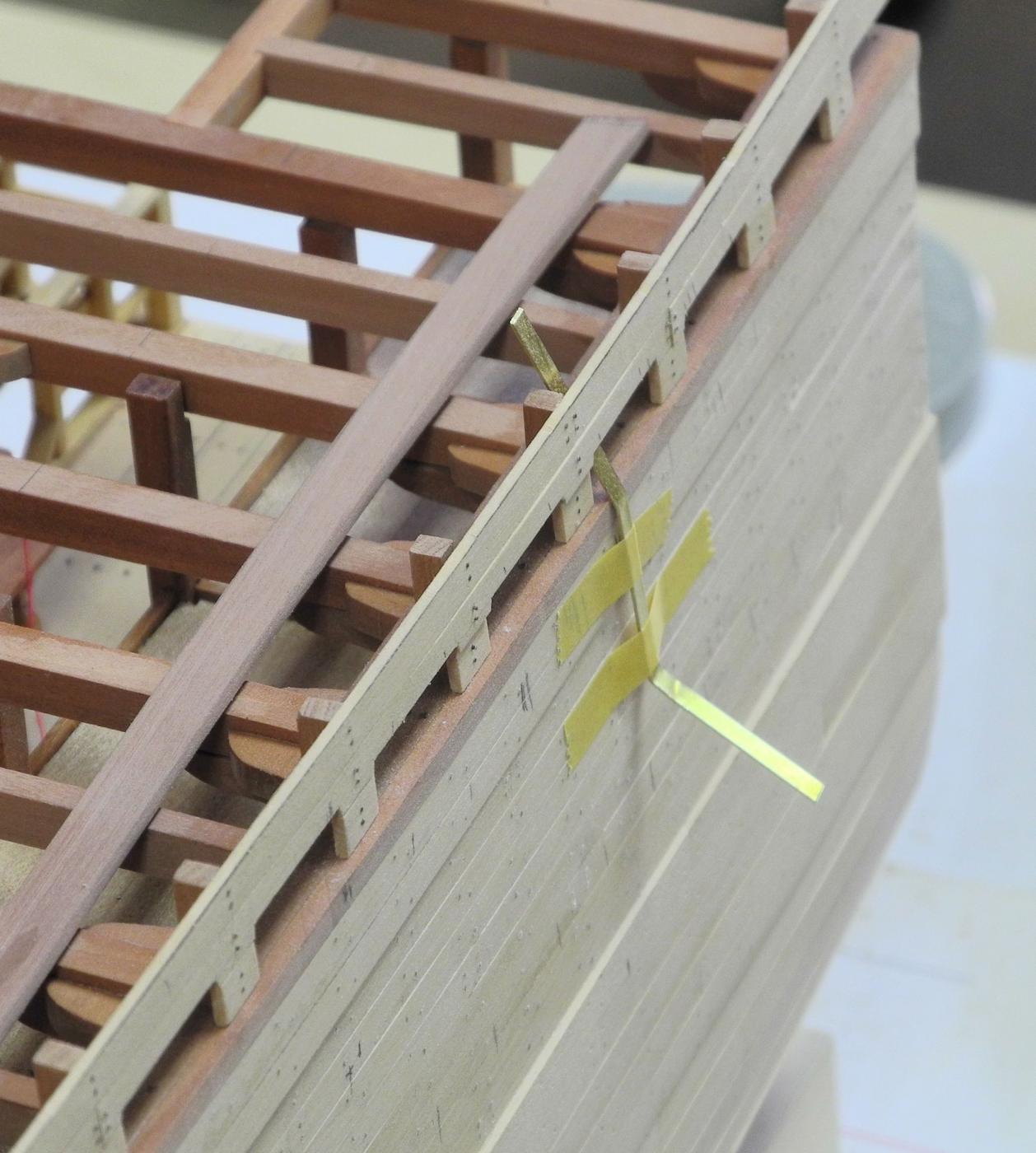
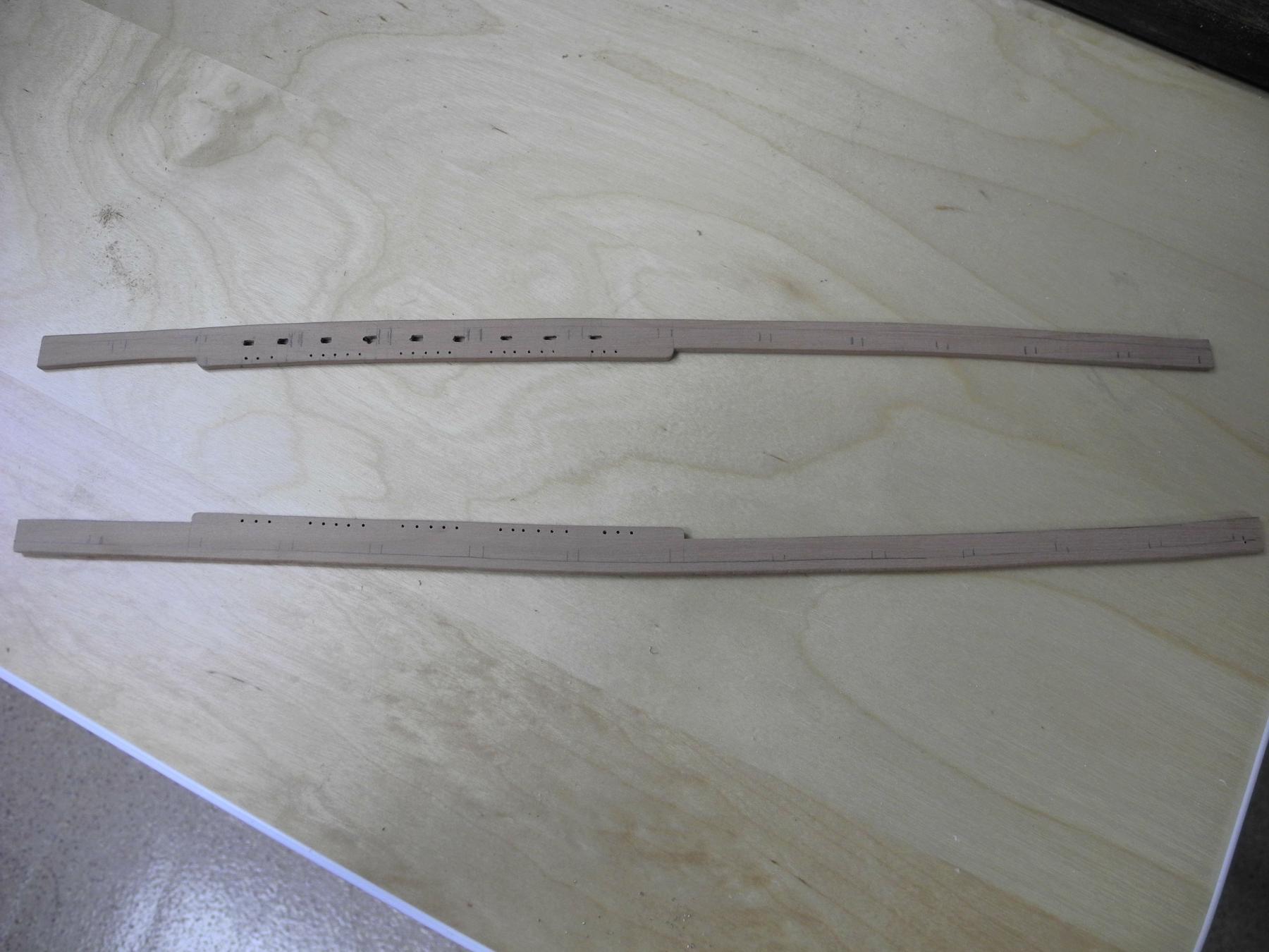
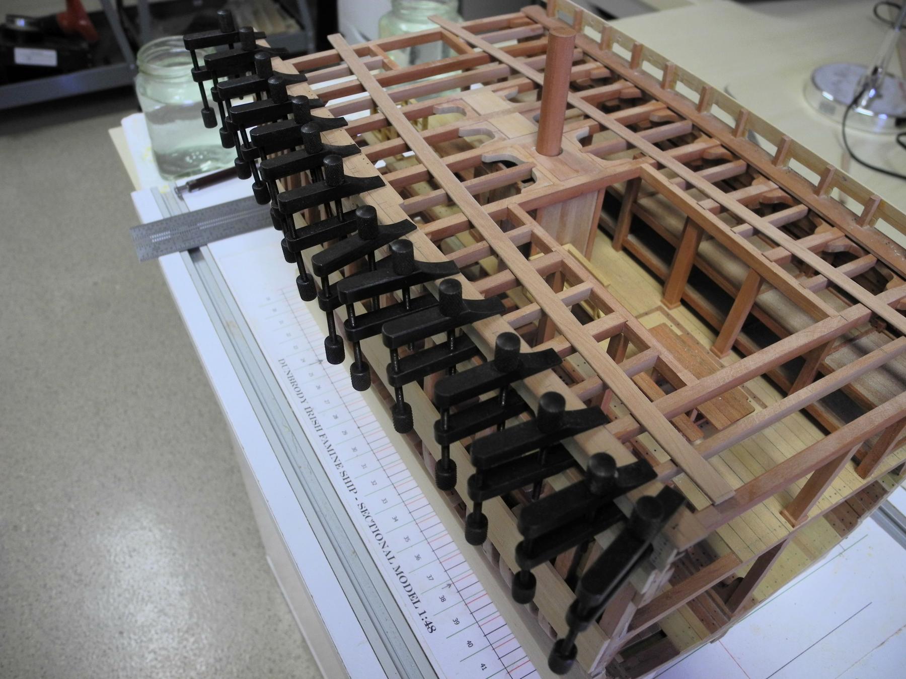
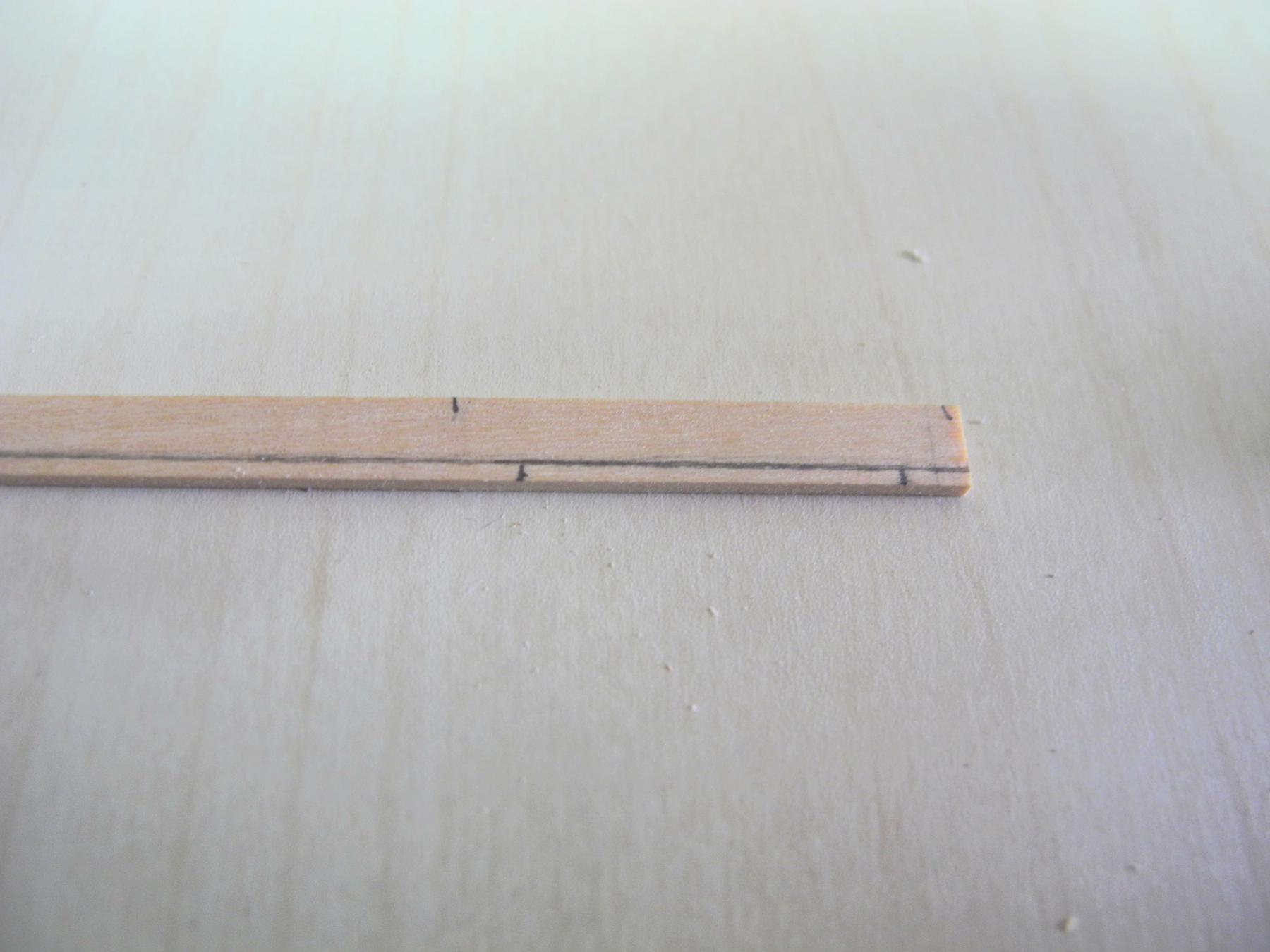
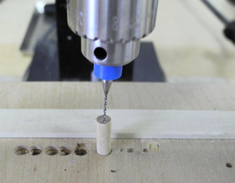
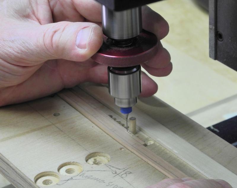
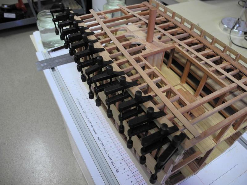
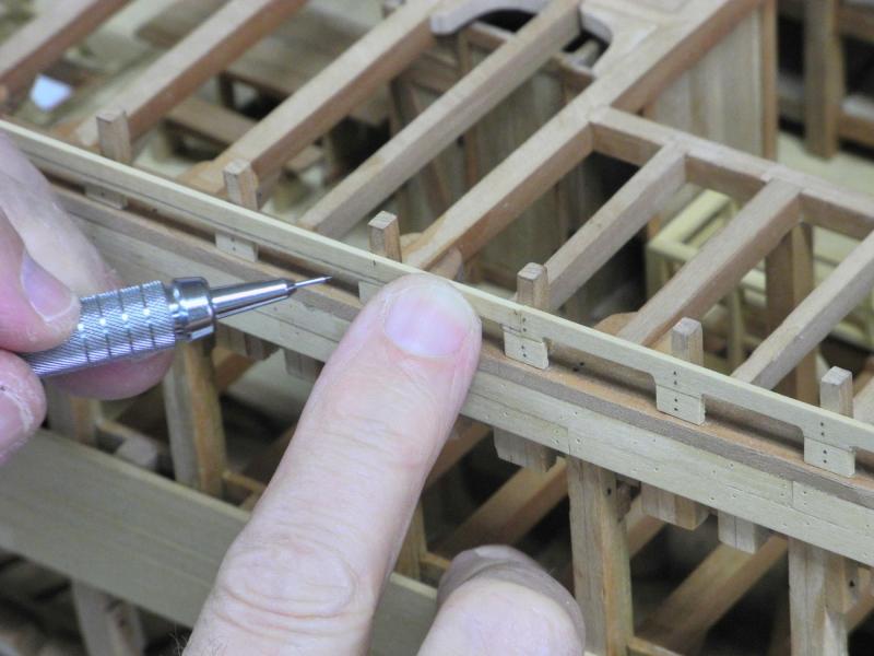
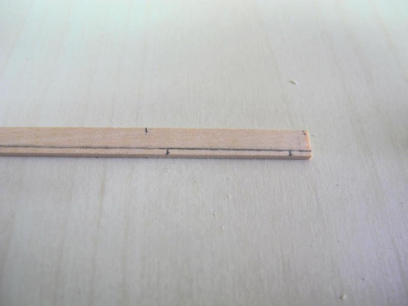
Part 45 – Main Rails The main rails are 4.5 inches thick (3/32 on the model). I decided to make them from a single piece of stock for simplicity. The stock was clamped in place and a line was drawn following the contour of the outer side of the bulwark planks. This edge was cut and sanded to shape. The outboard edge of the rail is rounded, while the inside edge is squared off. To make the profile for the outer edge a scraper was cut to the correct shape. The scraper was drawn along the outer edge until the edge was properly rounded, and then light sanding finished the edge. The chainplates will protrude through holes that are cut into the rails. In order to properly locate the chainplates a simulated mast and shrouds was used. The thread simulating the shrouds was fed through the scuppers to indicate the location of the chainplates. The bulwark planks are notched to allow the chainplates to sit properly. These notches are also needed on the model, and were cut in with small files. (Thankfully these notches will not be visible once the chainplates and rails are installed) Pin rails are integrated into the main rail in the area of the shrouds. Lines were dawn on the rails indicating the inside edge of the rail and the location of the pin rails. Once these were cut the location of the pins was marked on the pin rails for drilling. Since the inboard edge of the rail is a convex curve, a peg was used in the drilling station as a stop for the rail – this allowed drilling the holes at a consistent depth from the edge. A piece of brass stock of the dimension to be used for the chainplates was bent to the angle of the chainplate, and was attached to the exterior at the location of each chainplate. This was used to mark the location of the chainplate on the rail. Since the chainplates will only be installed on the finished port side of the model, the port rail was cut for the chainplates to pass through. Again, thankfully these holes will not be visible once the chainplates and topgallant rails are installed. The rails were then glued to the stanchions and the upper bulwark plank. A large number of clamps was used to ensure that the rails conformed to the sheer of the deck. Now the topgallant rails, including the bulwark planking and the small stanchions for the rails, need to be installed. This will be the subject of the next post. Thanks everyone!


- 649 replies
-
- 25
-
-
- dunbrody
- famine ship
- (and 2 more)
-
Hi Bob. On the replica ship there are many more upper stanchions than lower. The construction plans don't show the upper stanchions at all. In the photos of the replica ship some of the upper stanchions appear to loosely line up with the lower stanchions, and then additional upper stanchions are located between them. My approach will be to first line up the upper with the lower stanchions, and then to position the additional upper stanchions between them. Thanks Albert. Thanks Rich.
- 649 replies
-
- 4
-
-
- dunbrody
- famine ship
- (and 2 more)
-
Hi Patrick. Shadow looks to have beautiful lines. The extra care you're taking in lining everything up will definitely pay dividends.
-
Thanks Brian. I'm still thinking on the chainplates - may take a little while before they're done. Thanks Patrick. I'm enjoying most of it!
- 649 replies
-
- 4
-
-
- dunbrody
- famine ship
- (and 2 more)
-
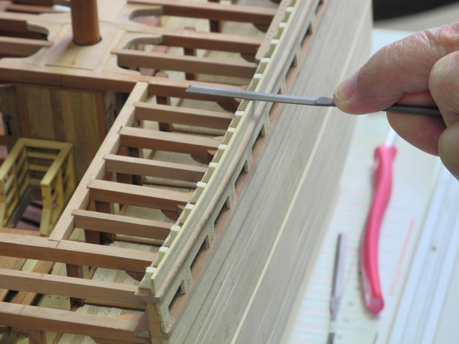
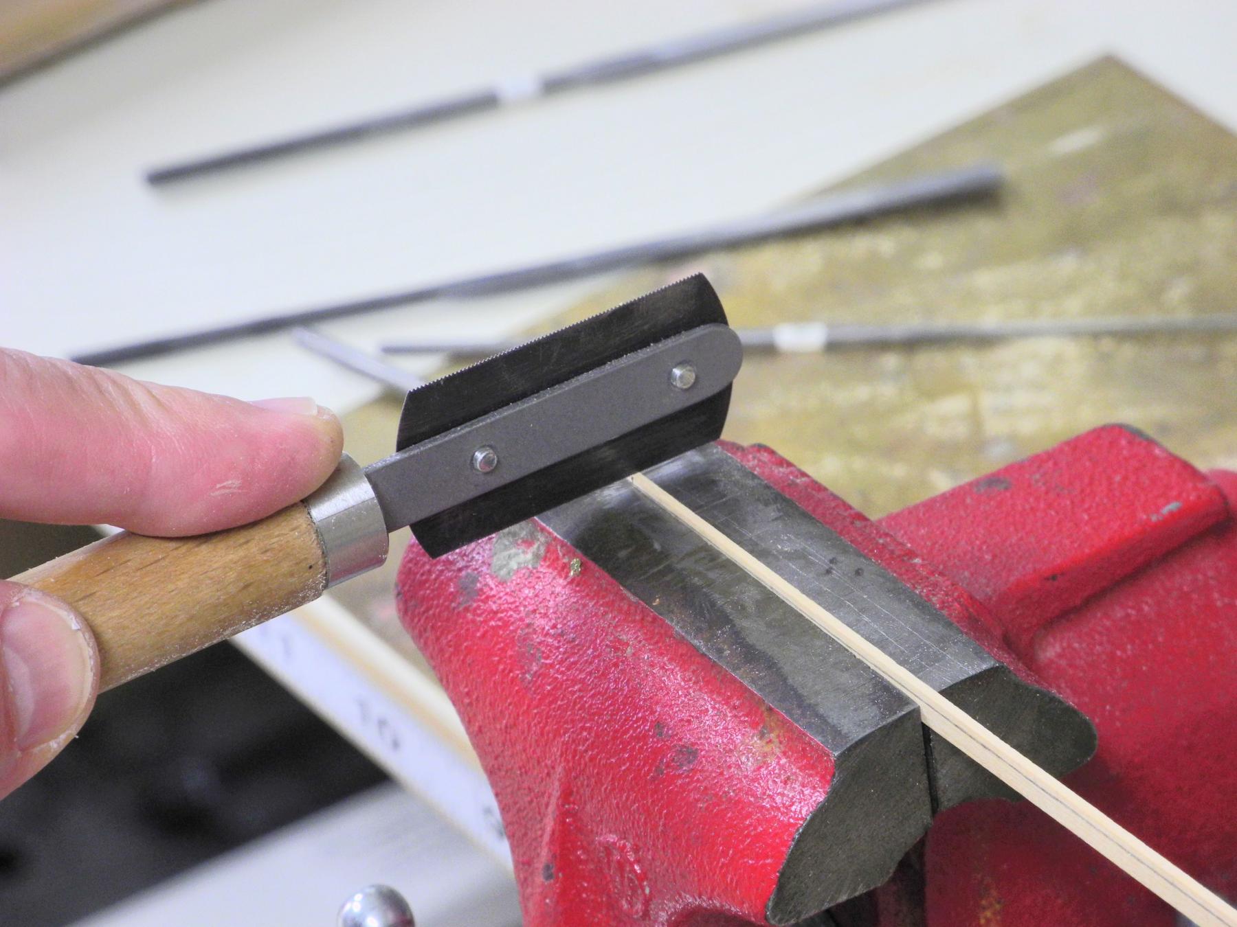
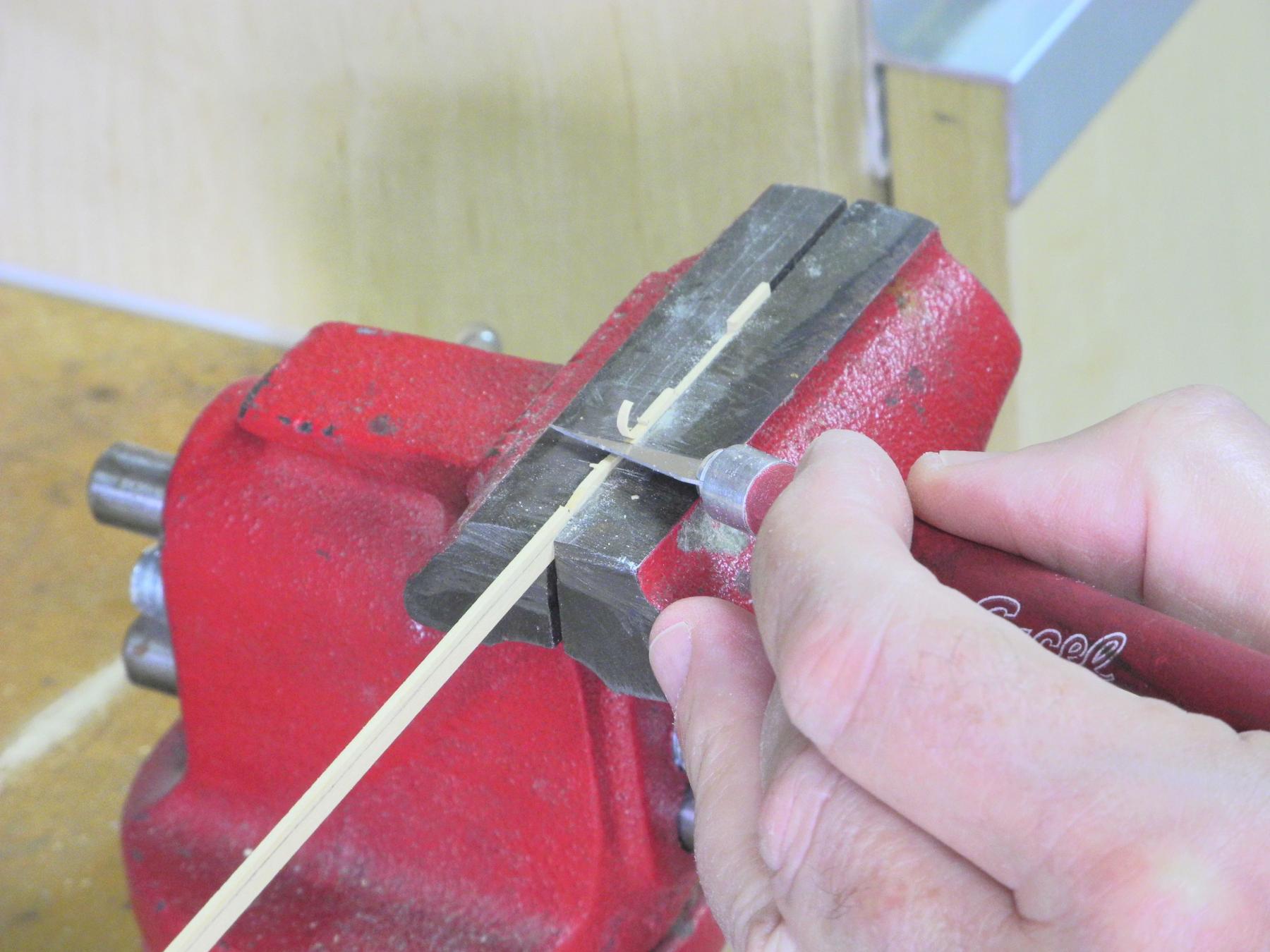
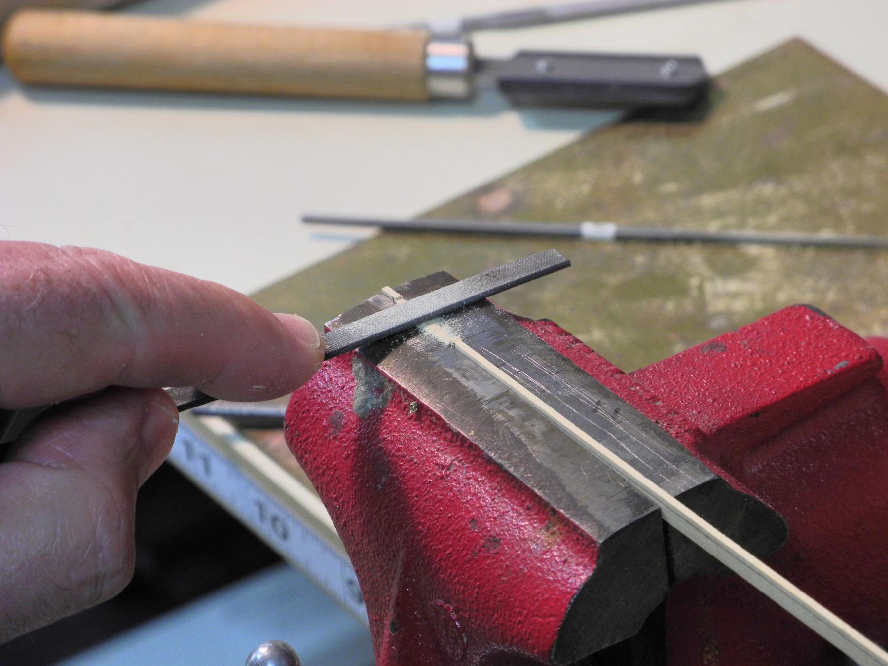
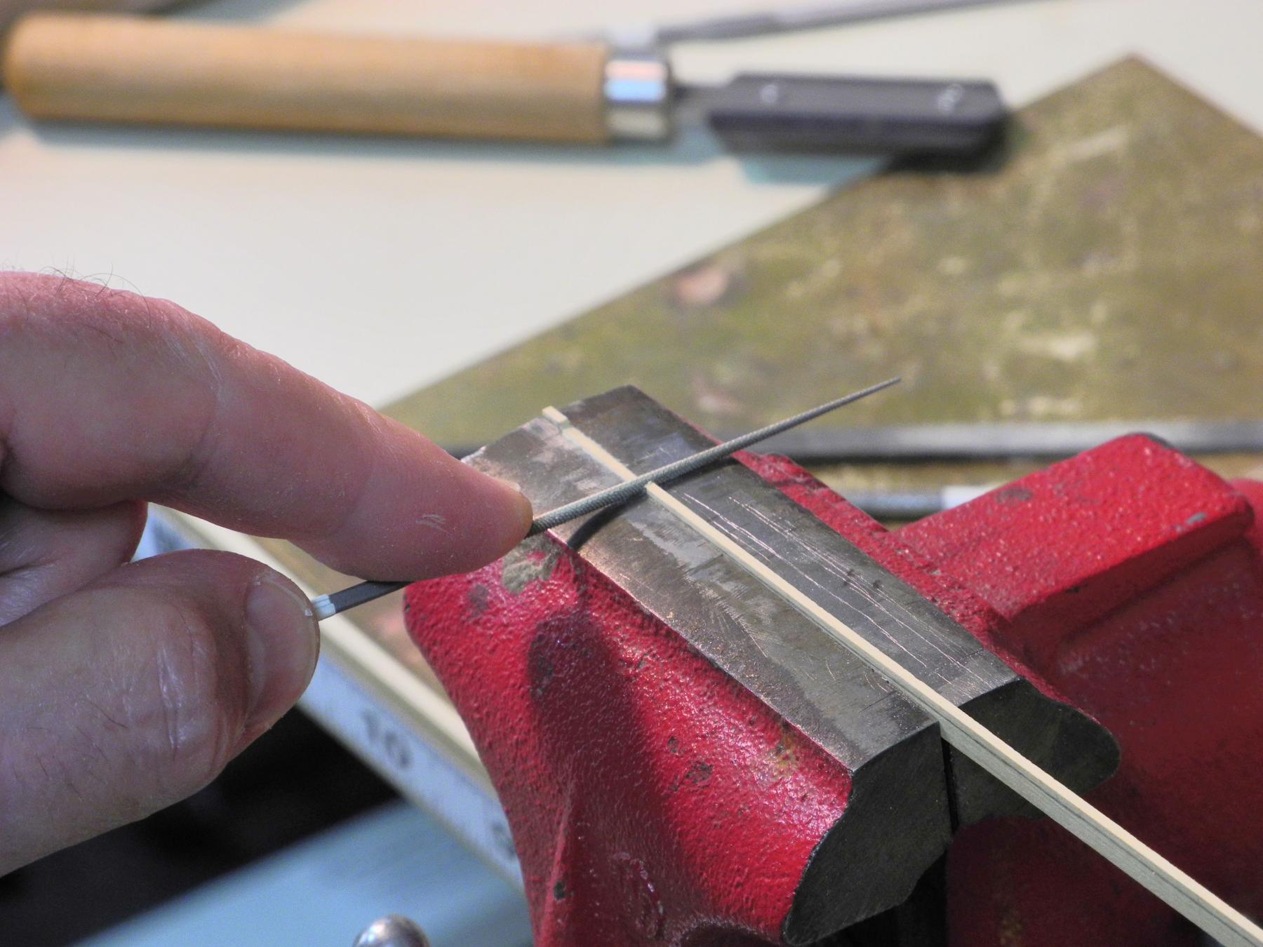
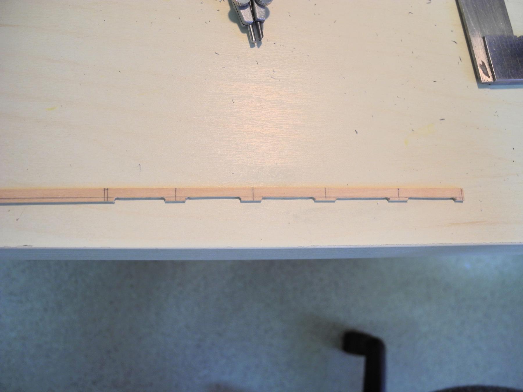
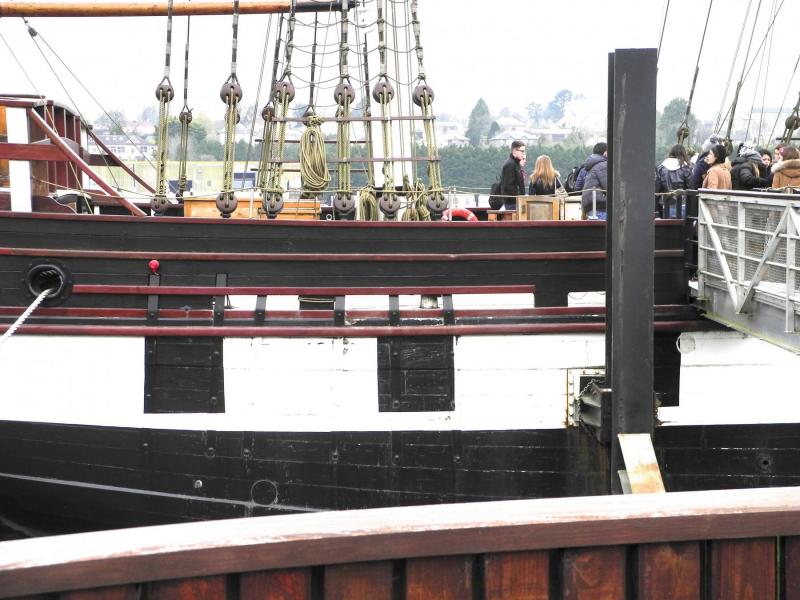
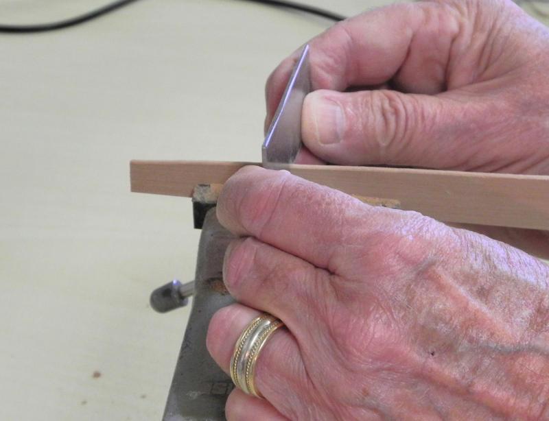
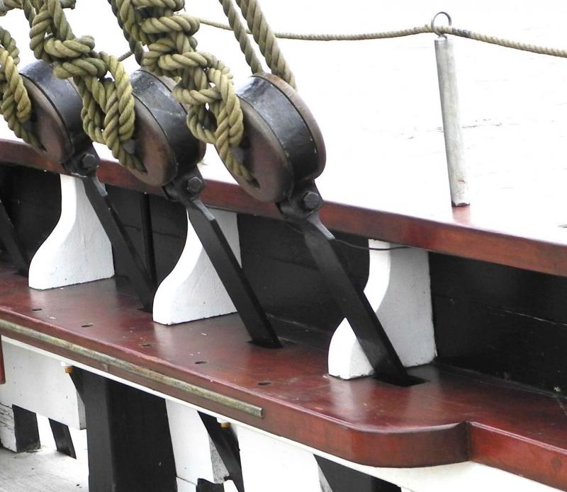
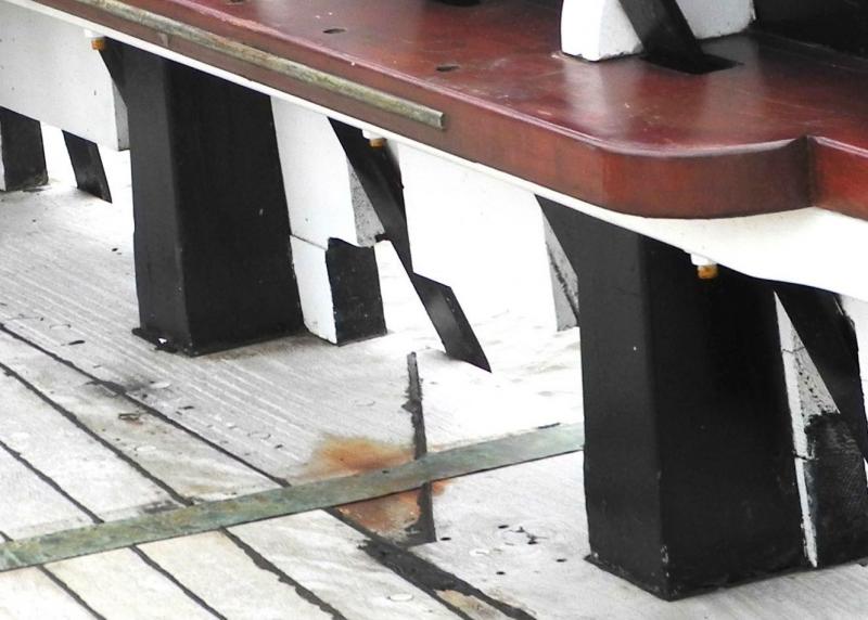
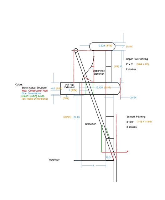
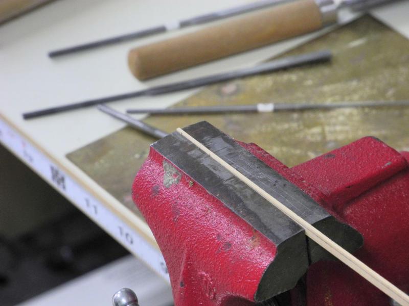
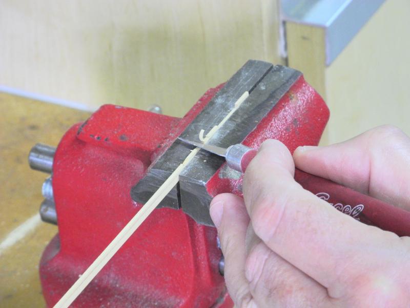
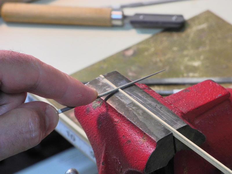
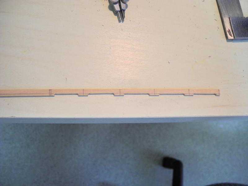
Part 44 – Bulwarks As shown in the final photo of my last post, the main deck railings are fairly complex. Scuppers are cut through the lowest bulwark plank, and partially into the next higher strake. The upper corners of the scuppers are rounded. The chainplates come through these scuppers, and are partially cut into the next higher strake of bulwark planks. There are partial planks located at each stanchion, presumably to serve as spacers for aligning the next higher strake of planks. The first order of business was to draft the construction of the main deck rails, as seen in the following photo: This drawing will help to determine several things: the angle of the chainplates, the depth of the rails and pin rails, and the size and shape of the smaller stanchions supporting the topgallant rail. With all of this in mind, I decided to install the bulwark planks prior to any other work on the main deck rails. The first step was to install the spacers, or pieces of what would have been the first strake of planks. The scuppers were then marked on the plank that would form the second strake. Since the scuppers are partially cut into the plank, a line at the correct depth was drawn across the entire plank. Then marks indicating the fore and aft sides of the scupper were made. The strake was then held upside-down in the vise, located so that the bottom horizontal drawn line was aligned with the jaws of the vise. Stop cuts were made with a razor saw, slightly inside the marked lines. The plank was carefully pared back to the stop cuts. The end of the scupper was then rounded, using a small round escapement file. The horizontal border of the scupper was then filed down to the jaws of the vise. The plank was then held against the stanchions and the locations of the bolt holes were marked. The bolt holes were drilled, copper wire was inserted as simulated bolts and blackened with liver of sulphur. The strake was then glued in place. After the strake with scuppers was completed, the top strake of the bulwark planks was installed. The next step will be shaping the main rail and topgallant rail, followed by creation and installation of the small stanchions that will support the topgallant rail. In the meantime, installation of treenails in the hull planking is continuing. Thanks everyone for the ‘Likes’ and comments.


- 649 replies
-
- 18
-
-
- dunbrody
- famine ship
- (and 2 more)
-
Hi there Popeye! Great to have you aboard. Thank you so much for the great comments and all of the 'Likes'. The scarf joint wasn't the only error by far - my scrap box can attest to that. Some errors I've been able to do-over, while others can't be fixed and will always be there to make me cringe.
- 649 replies
-
- 6
-
-
- dunbrody
- famine ship
- (and 2 more)
-
Hi Alan. These clamps will hold planks in place, but they don't have the force of other clamps so they don't impart much pressure on the joint. That being said, they are useful in some situations.
- 649 replies
-
- 6
-
-
- dunbrody
- famine ship
- (and 2 more)