Mahuna
-
Posts
1,504 -
Joined
-
Last visited
Content Type
Profiles
Forums
Gallery
Events
Everything posted by Mahuna
-
 Thanks Brian. My better half agrees that I should leave the knees, so I'm leaning that way. By the way - the passengers didn't get into the hold, I think. Thanks Patrick. I was happy to see Magellan again.
- 649 replies
-
- 6
-

-
- dunbrody
- famine ship
- (and 2 more)
-
Well done Patrick - looks as good as new. I've missed the Magellan updates and I'm glad it's back on track.
-
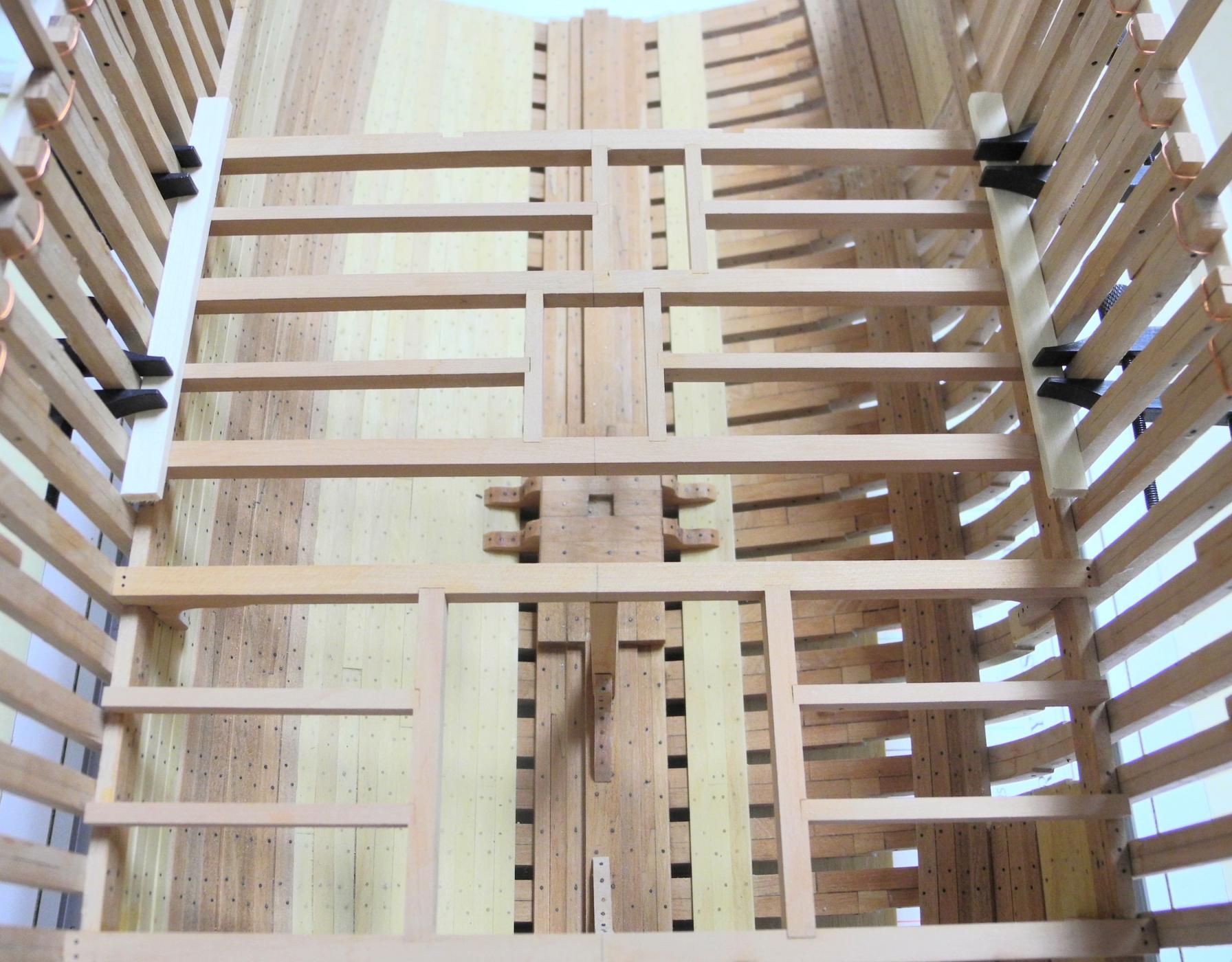
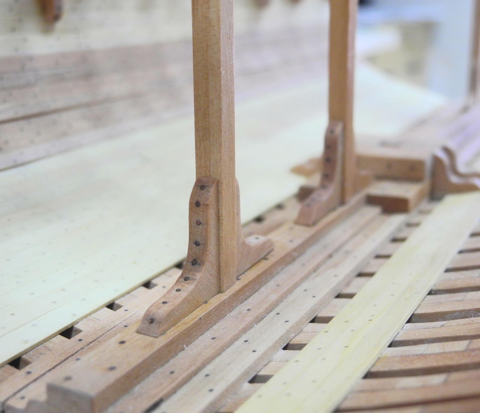
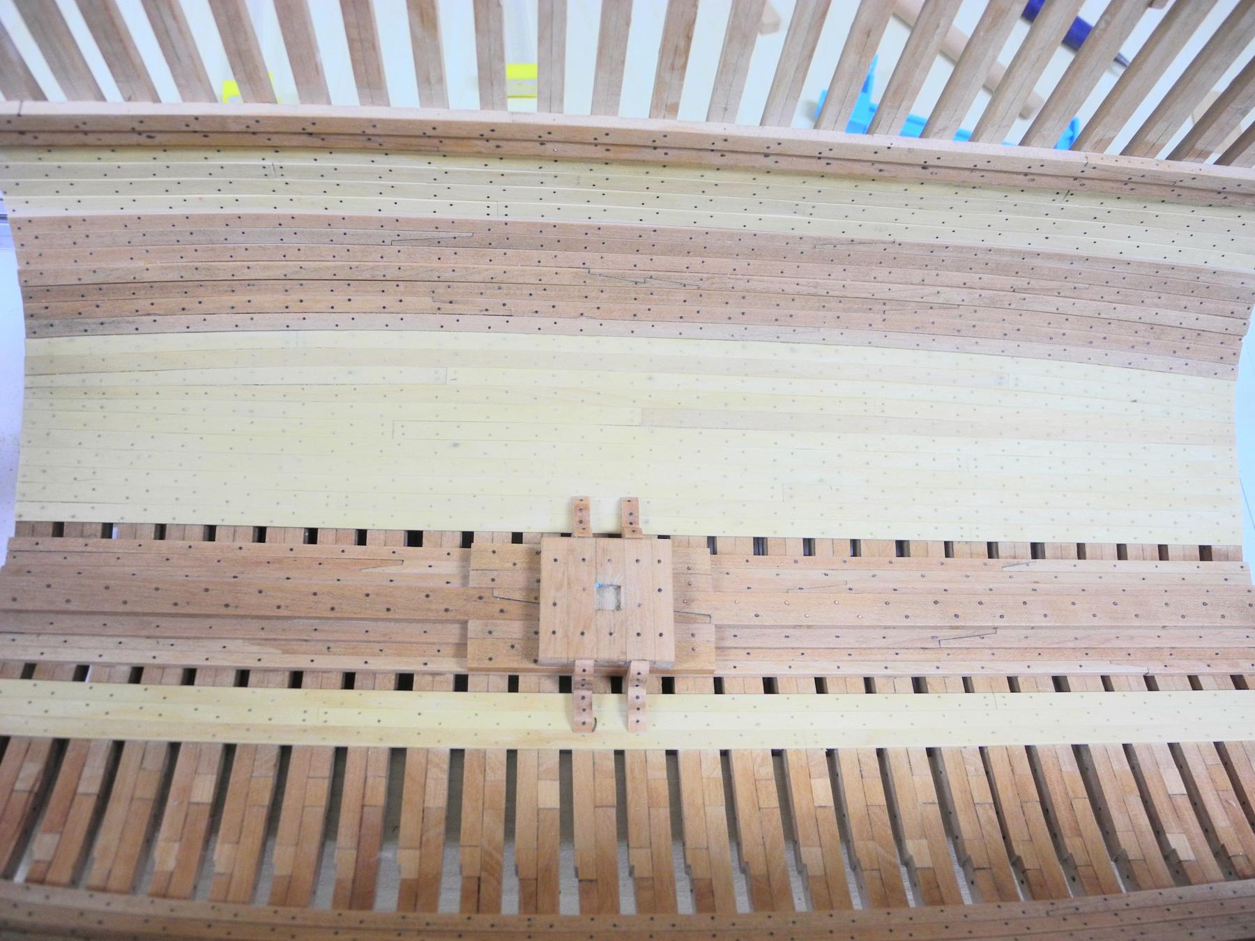
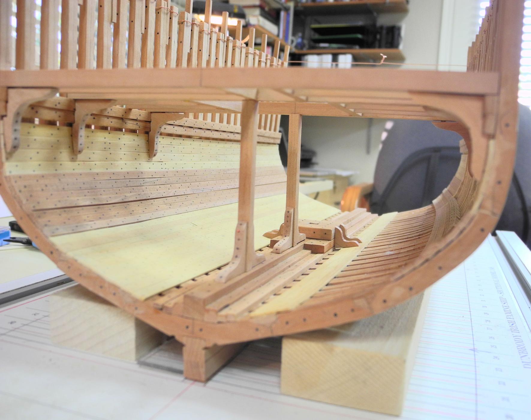
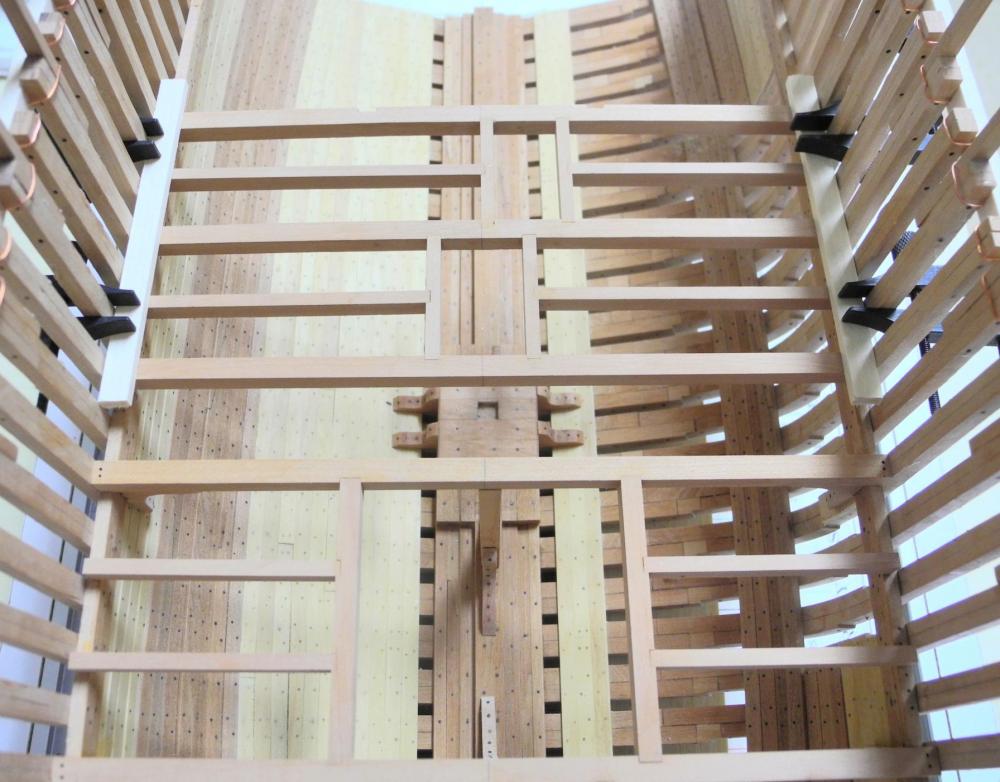
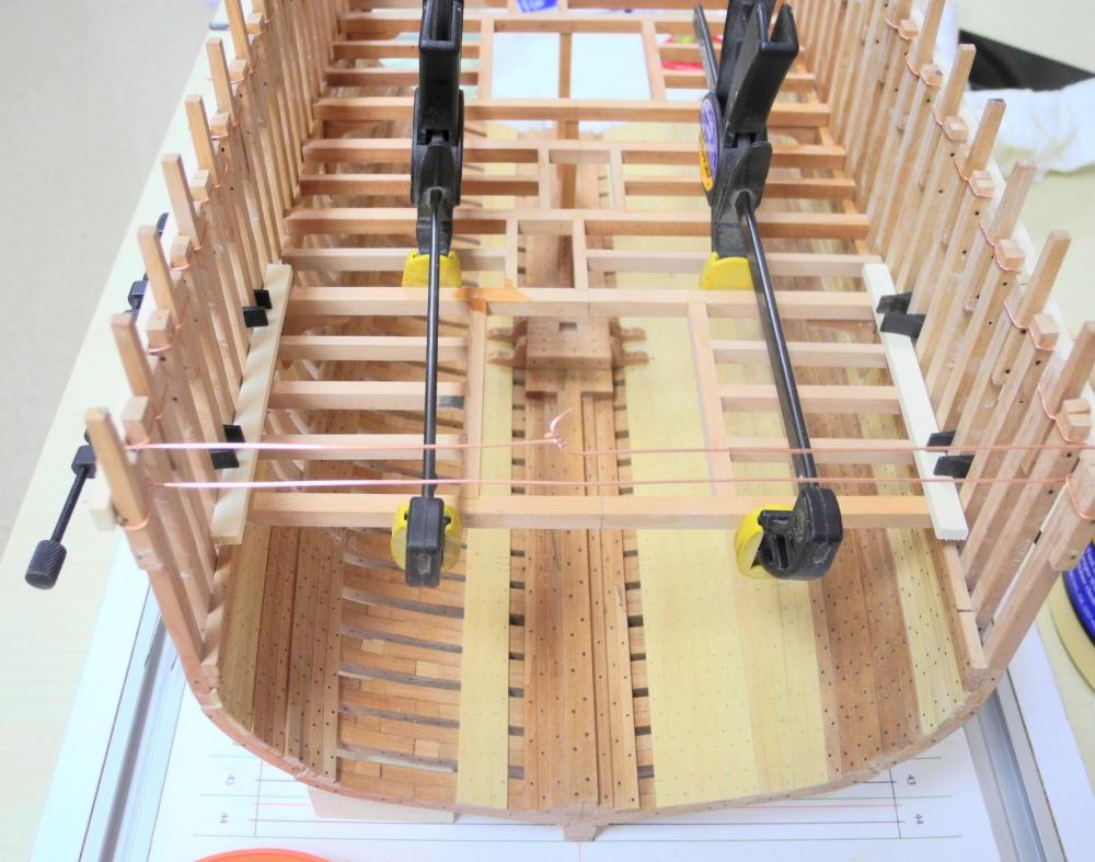
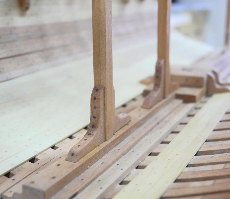
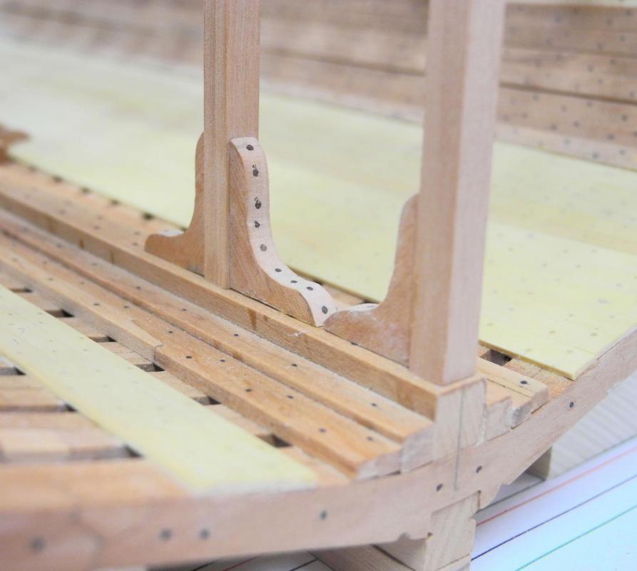
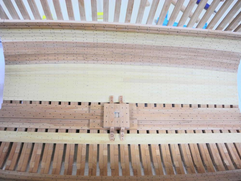
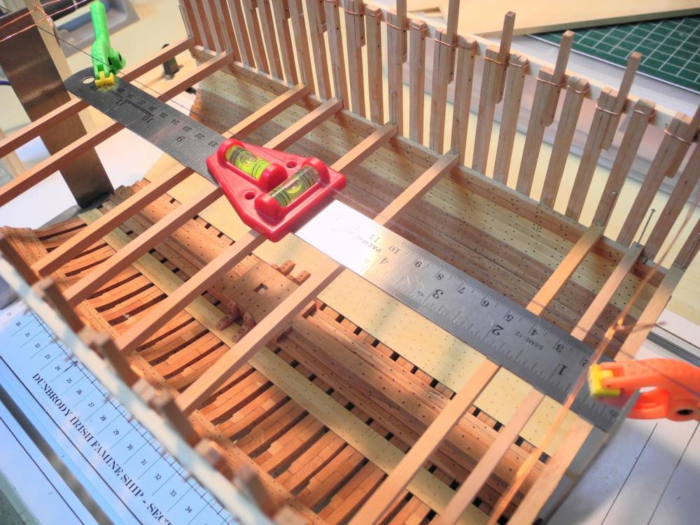
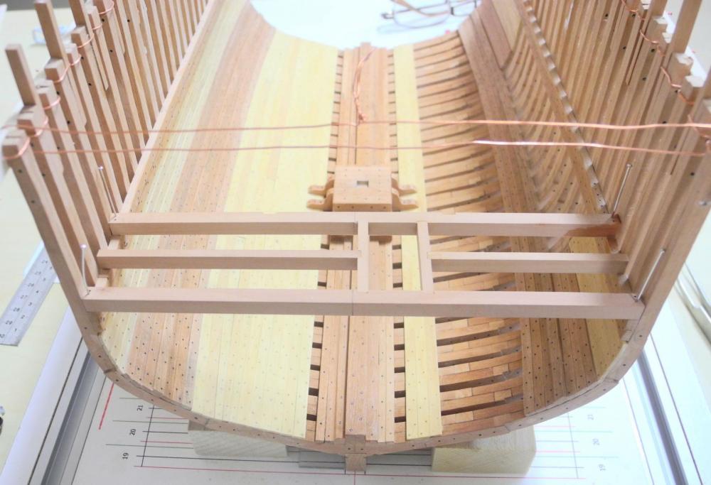
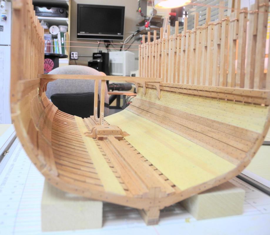
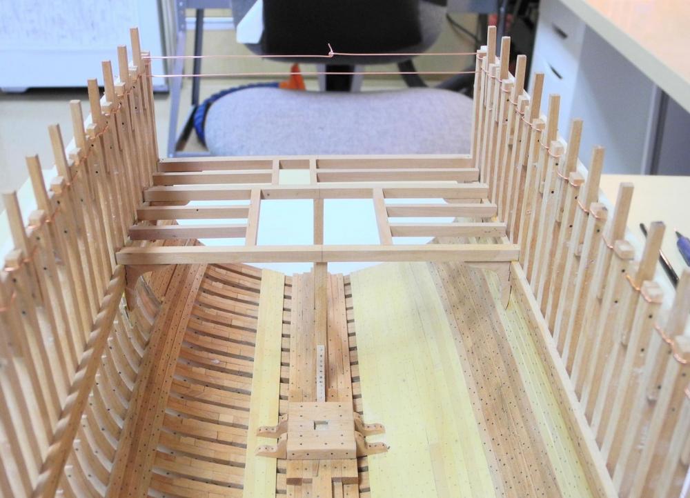
Part 27 – Accommodation Deck Beams Cont’d I’ve had a few days out of the shop, but now I’m back to work. Installation of the beams for the Accommodation Deck has continued. I was able to glue up the next beams – those for the mast partners and the forward companionway – off the model, and then to install them as a sub-assembly. To ensure that all beams were properly seated on the shelf, I laid a straight piece of stock across all of the beam ends, and then used the small machinist clamps to press down on that stock. The forward-most beam in that sub-assembly also forms the aft beam of the forward hatch. I assembled the rest of the hatch beams and glued them together off the model. When they were set they were added to the deck as another sub-assembly, using the clamping arrangement in the following photo. Hanging knees were installed in the middle of the forward hatch, and also to the forward-most beam of that hatch. A stanchion was also installed at the forward-most beam of the hatch. The last two beams to be installed were single beams – not part of any assembly. The forward –most beam has hanging knees and a stanchion. This completed the installation of the Accommodation Deck beams. There are gaps between some of the hanging knees and the beams above them. The gaps can be seen in the photo above, but they are difficult to see when looking at the model – some contortions would be required to pick them out. I’ve been wrestling with a question about the stanchions and I’m open to comments and suggestions on how to proceed: During the period when Dunbrody was built, stanchions were held in several different ways: by standing knees as I used in the model; by iron straps and clasps at the base and top of the stanchions; and by simply bolting them in place. Unfortunately, the construction plans don't provide any information that would indicate the method of supporting the stanchions. I decided to use the knees because I thought it would look more complete, and I used the proportions shown in some drawings from the Crothers book (the height of the knees is 20-25% of the height of the stanchions.). The knees looked too big when I first constructed them and I reduced them in size. I’m still concerned that the knees might be too much of an obstruction in the hold. The model is at the point where the stanchions and knees could still be removed and the stanchions redone. I think if I did away with the knees I’d try to make straps for the base of the stanchions but probably not for the top. If anyone has an opinion or suggestion on how I should proceed with the stanchions (leave the knees in or replace them with straps or bolts) I’d appreciate hearing from you. Thanks for following this build , and thanks for the continued encouragement.


- 649 replies
-
- 18
-
-
- dunbrody
- famine ship
- (and 2 more)
-
Hi Rich. Thanks. Progress has slowed for the last few days due to out-of-town company (I guess New Jersey wasn't hot enough), but I'll be back in the shop tomorrow and hope to post some more updates soon.
- 649 replies
-
- 4
-
-
- dunbrody
- famine ship
- (and 2 more)
-
Beautiful work Glenn. With each post you inspire me to do my work as cleanly as possible, trying to achieve your level of craftsmanship.
-
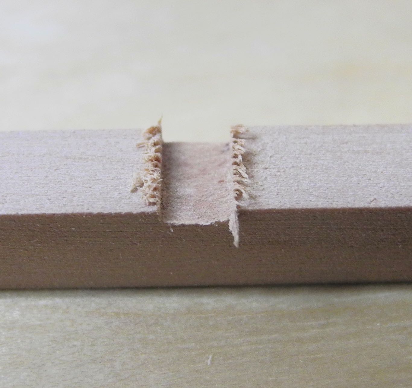
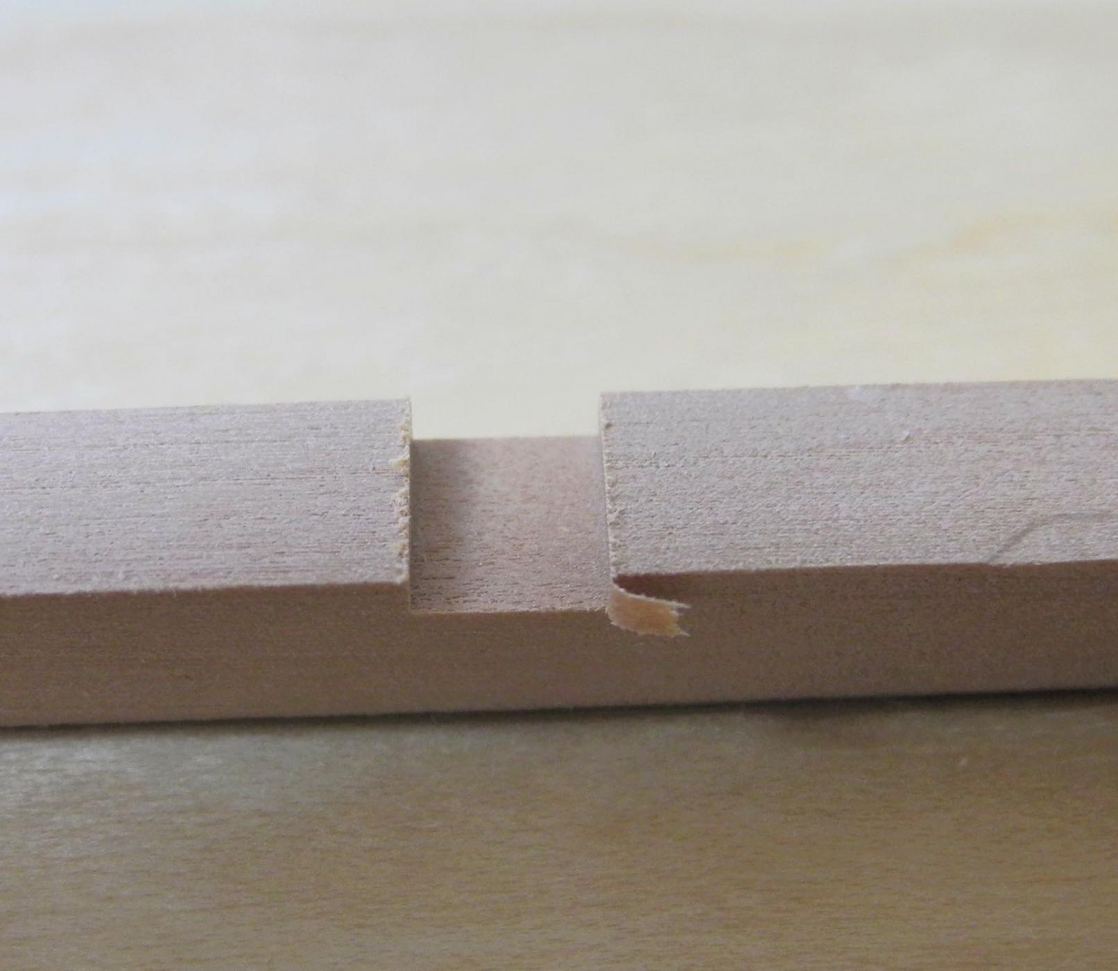
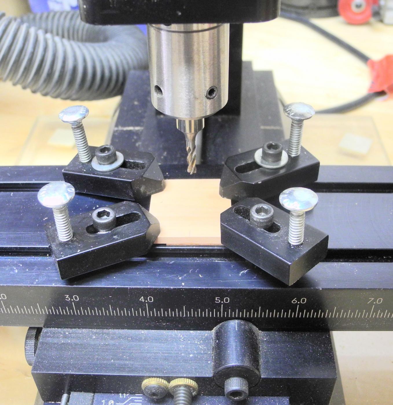
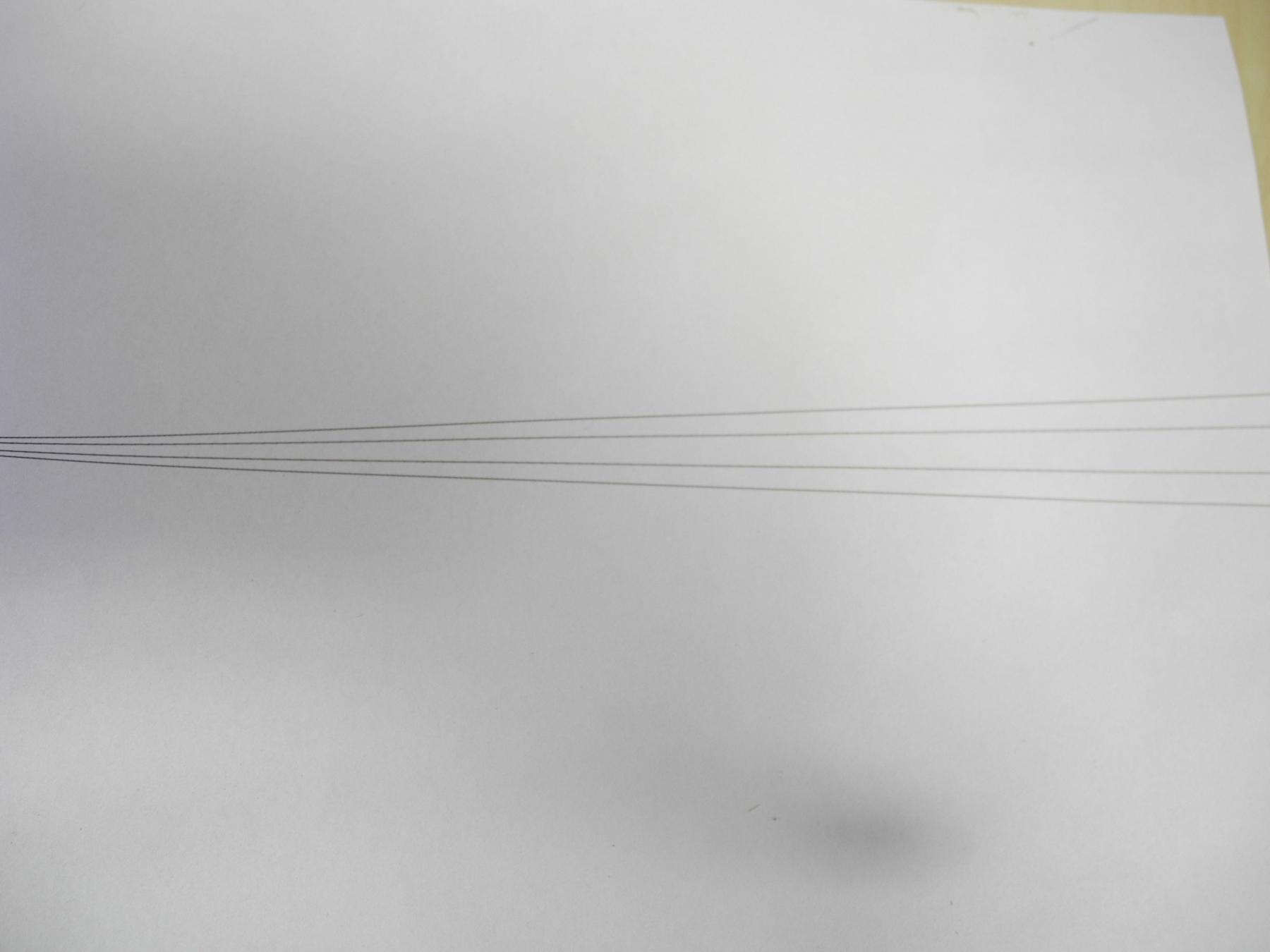
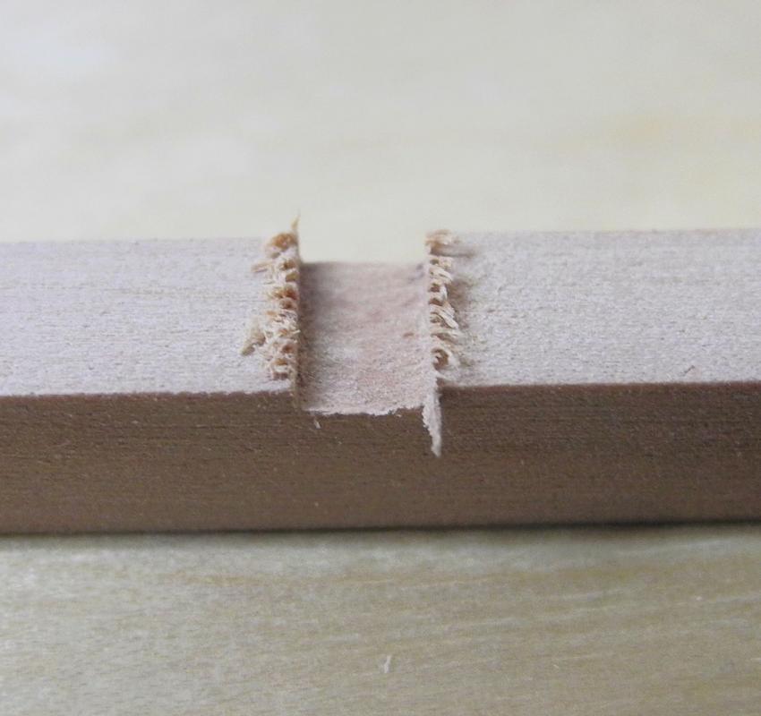
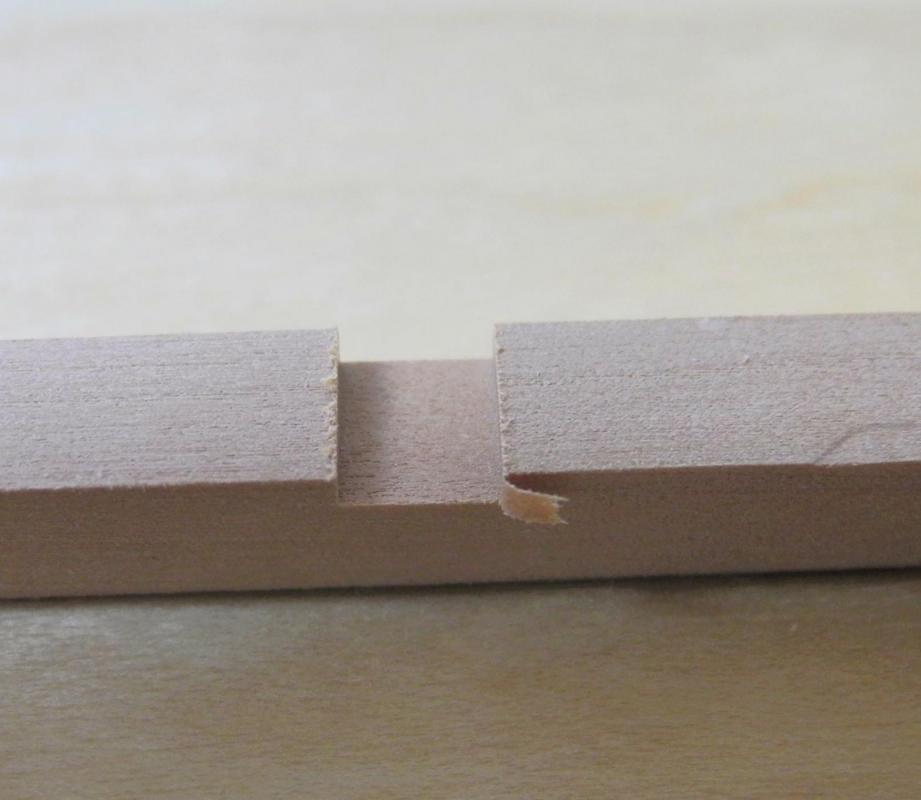
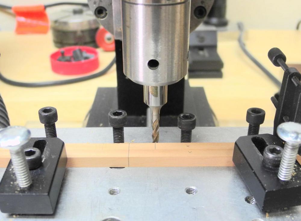
Just thought I'd share a little lesson I learned this week. My milling machine and all of the related tools were bought as used equipment - in the neighborhood of 15 years old when I got them. The end mills all seem to cut metal OK, but cause a lot of tear-out in wood. I thought this was normal, until I had to buy a new end mill of a size I needed and didn't have. The difference in cut is amazing, so I think the old end mill must be dulled by years of use. Here's a cut using an old cutter. And here's a cut with the new cutter. Lesson learned - use a sharp end mill for cutting wood.
- 146 replies
-
- 11
-
-
Thanks Druxey. When I took the photo in the previous post I was mainly interested in the emigrants' sleeping quarters and wasn't even thinking about the knees (didn't know enough at the time to even consider it). It would be very interesting if there were details of the changes that took place in sailing ships from the napoleonic wars to the age of the clippers. The major changes in hull design and sail plans are obviously well-documented, but details like this one we wrestled with are hard to find - and it would be great to get answers to 'why' and 'when'.
- 649 replies
-
- 6
-
-
- dunbrody
- famine ship
- (and 2 more)
-
Welcome, Boyd. Thanks Bob. By the way, it looks like I may get up to your area sometime in early July. I'll bring Dunbrody with me.
- 649 replies
-
- 5
-
-
- dunbrody
- famine ship
- (and 2 more)
-
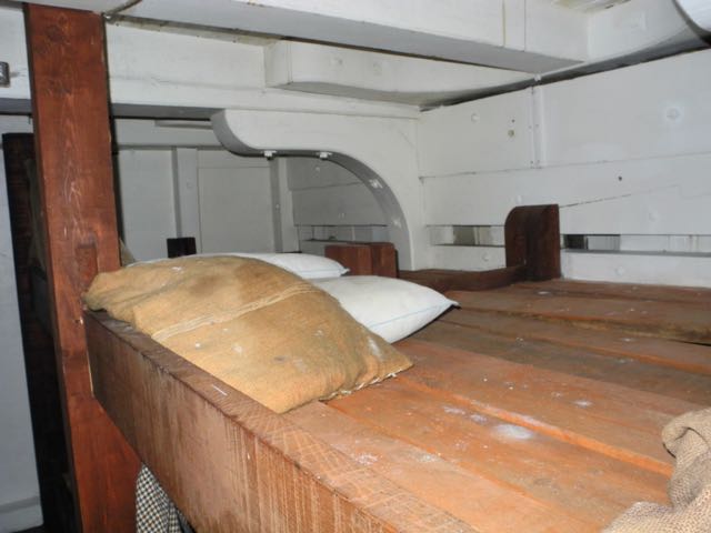
This has been a very interesting and informative discussion - thanks everyone - and it demonstrates one of the great benefits of this forum: the exchange of ideas. It also illustrates the need for research when building a model. I looked through my photos of the Dunbrody replica ship in New Ross, Ireland, and found this photo taken in the emigrants' living quarters on the accommodation deck. It clearly shows the hanging knee under the beam and the lodging knee on the side of the beam.
- 649 replies
-
- 16
-
-
- dunbrody
- famine ship
- (and 2 more)
-
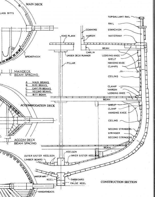
Hi Druxey: The Desmond book deals primarily with wooden ships. In his book, Crothers cites the Chatsworth, a ship-rigged packet built in 1854 as having between 11,000 and 12,000 'riveted bolts'. Here is the cross-section of the mid frame, showing the hanging knee under the beam. There are many similar pictures of various ships in the Crothers book - all with hanging knees shown the same way. If the knee were to be attached alongside the beam I would expect the drawing to show the upper part of the knee (probably as dashes) in at least one of those drawings.
- 649 replies
-
- 10
-
-
- dunbrody
- famine ship
- (and 2 more)
-
Druxey - I checked Ed's Naiad books (only books I have on Age of Sail warships) and found that the hanging knees are indeed installed as you said. I then checked the Desmond book on later period wooden ships and found the following: "The hanging knees are fitted to the underside of beams and to the side of vessel and fastened with through rivets driven at varying angles". So it seems to me that the method of installing hanging knees must have changed sometime in the 1800's. It's odd that neither of the books I'm using as references refer to the change. Thanks for bringing up a very interesting point.
- 649 replies
-
- 7
-
-
- dunbrody
- famine ship
- (and 2 more)
-
Thanks Mark - I found the laser at LittleMachineShop.com Thanks Ed. Your books and logs have been a marvelous help in the learning process. Thanks Druxey. The construction plan shows the knees under the beams. Also, Crothers says "The Hanging Knees, installed under the beam ends ..." - so I think they're in the right place.
- 649 replies
-
- 4
-
-
- dunbrody
- famine ship
- (and 2 more)
-
Thanks Brian. Hmm, I hadn't thought of that for the hatches.
- 649 replies
-
- 4
-
-
- dunbrody
- famine ship
- (and 2 more)
-
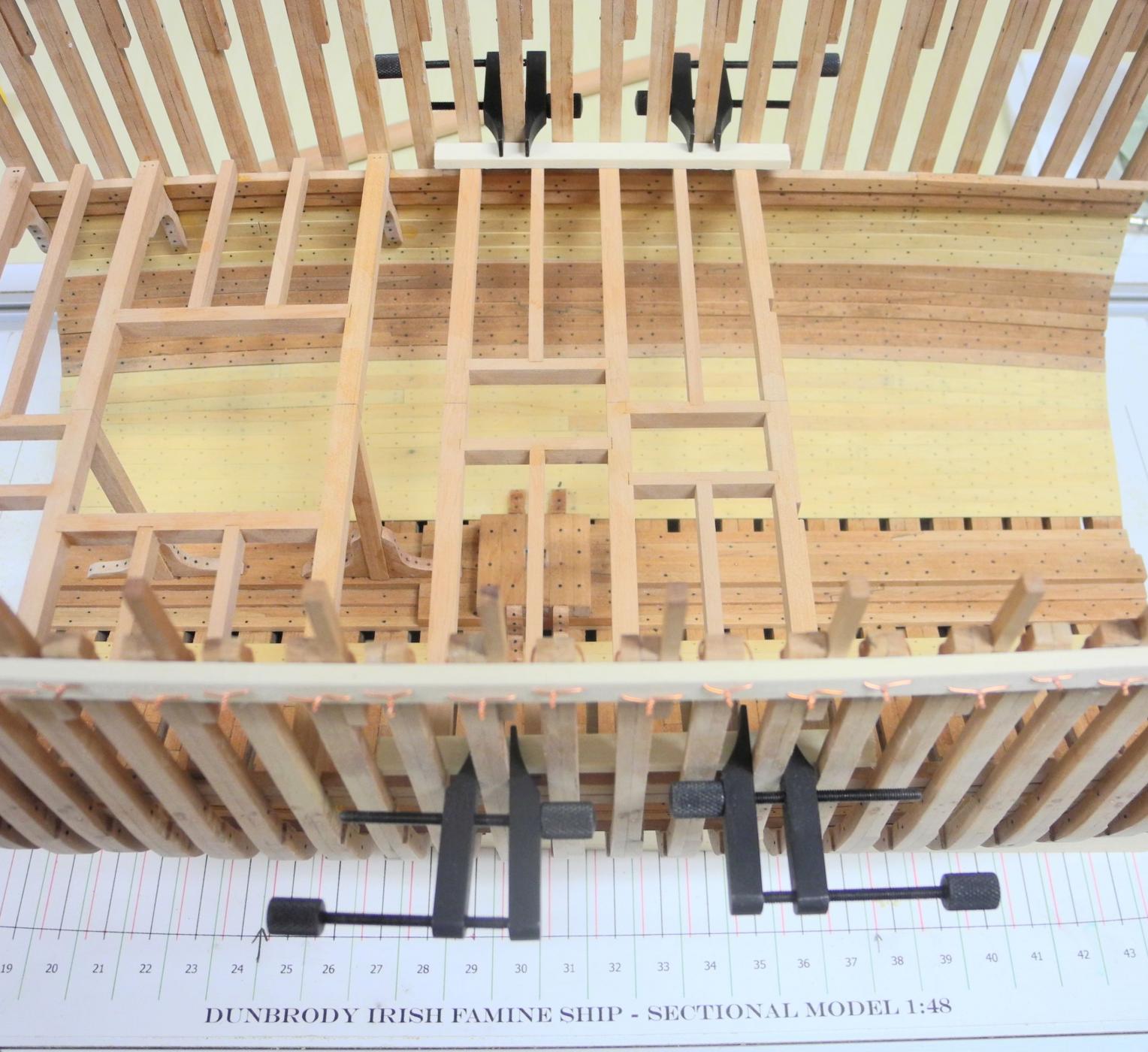
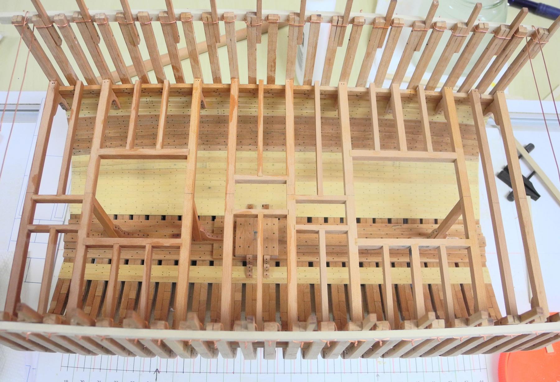
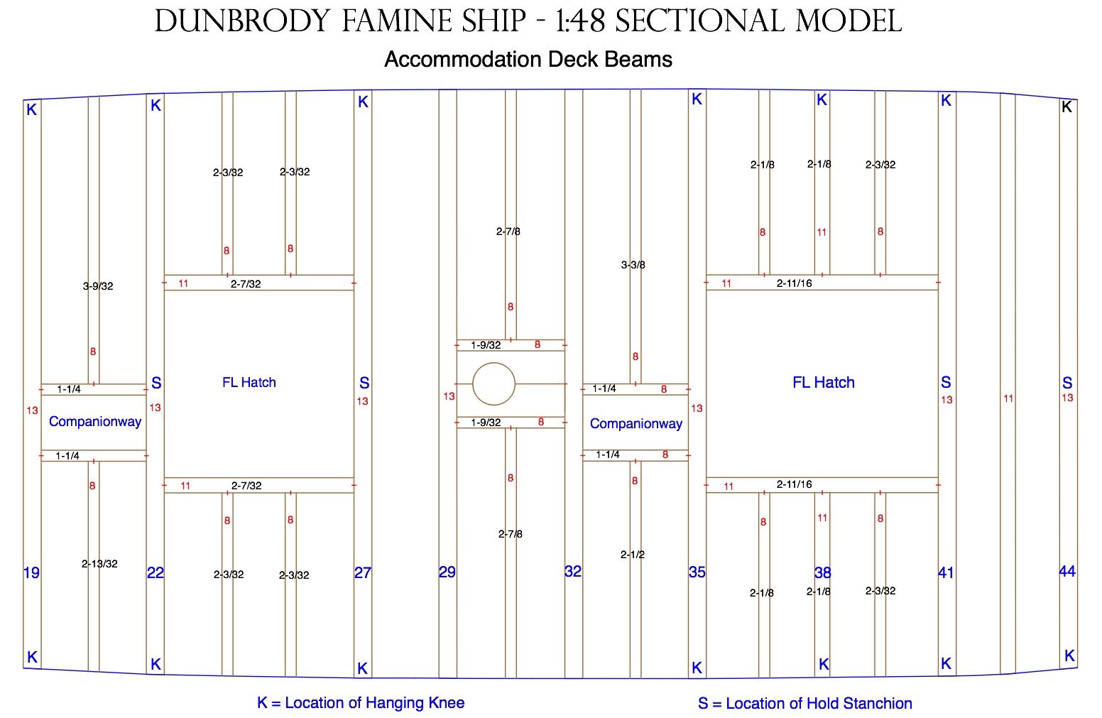
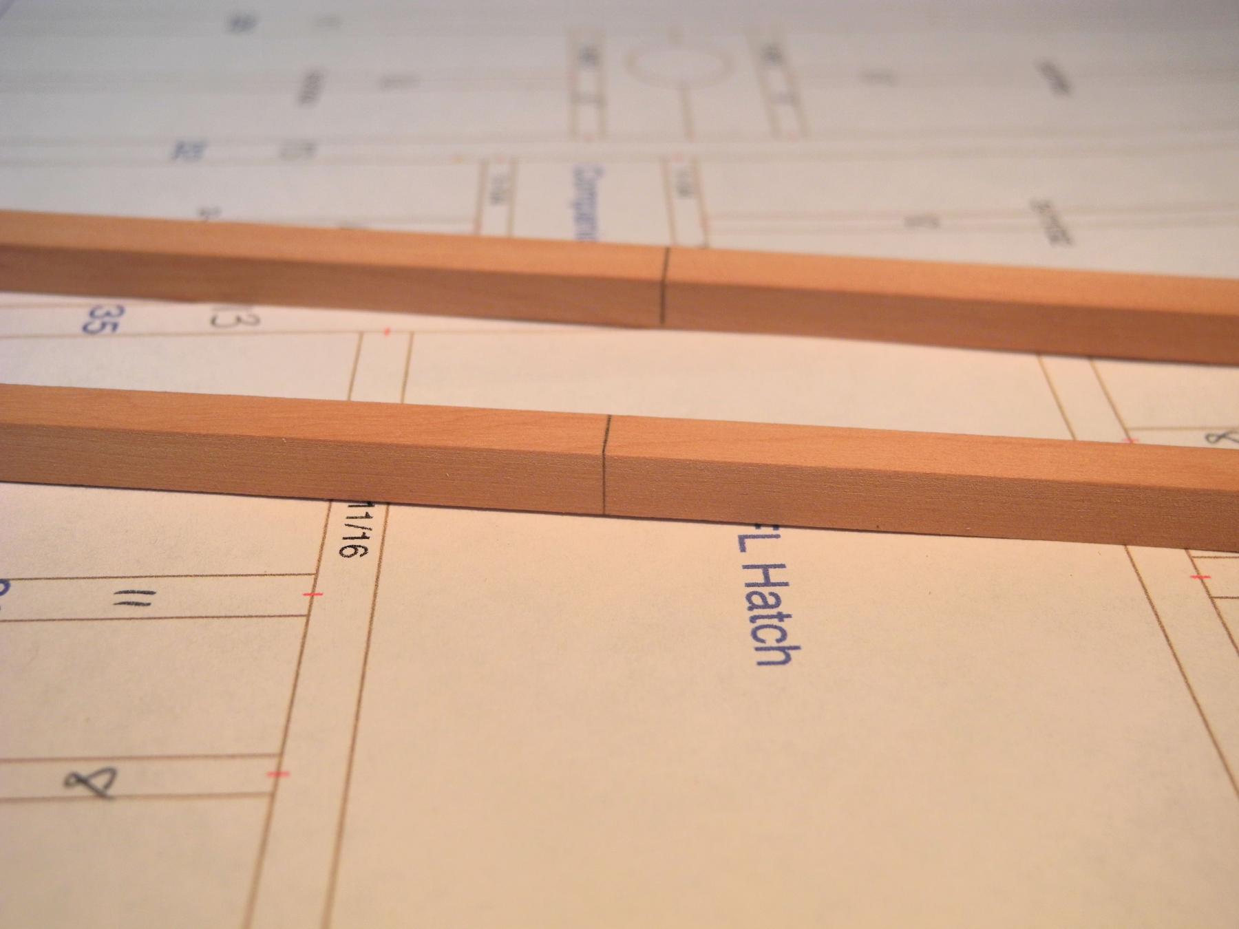
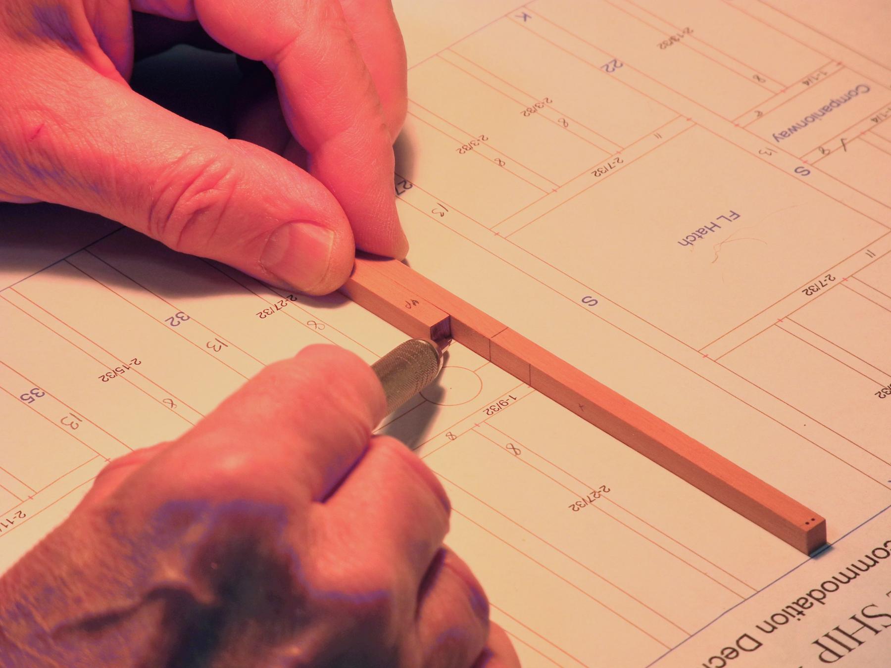
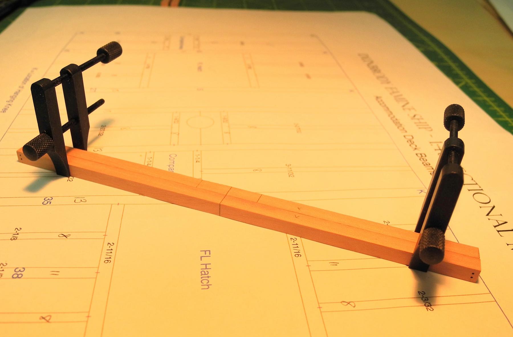
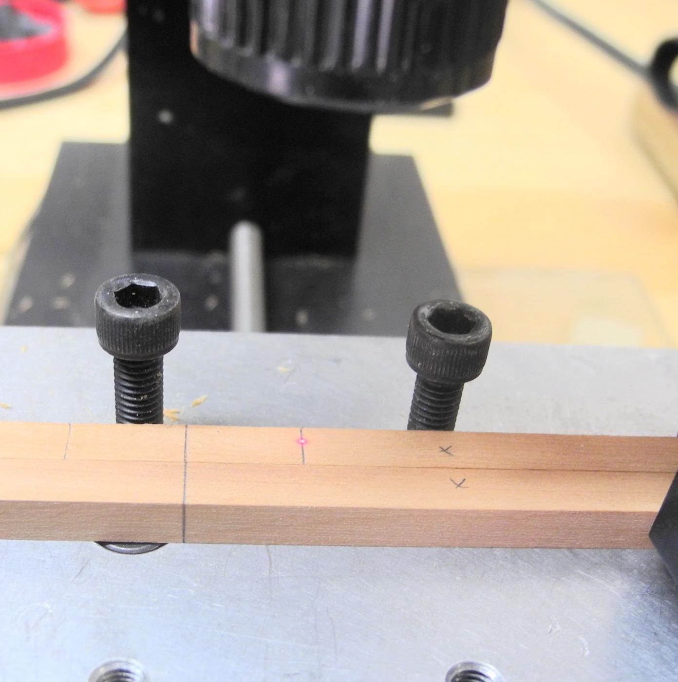
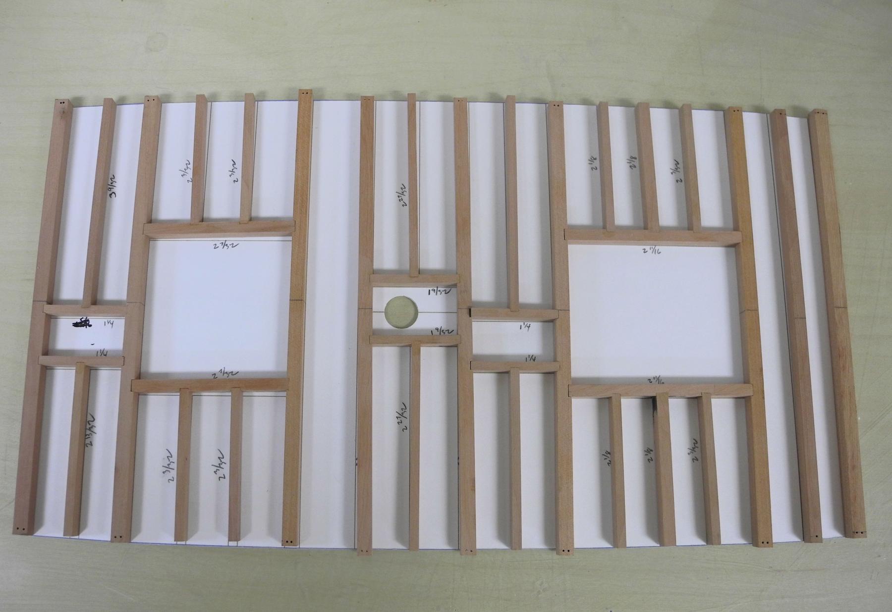
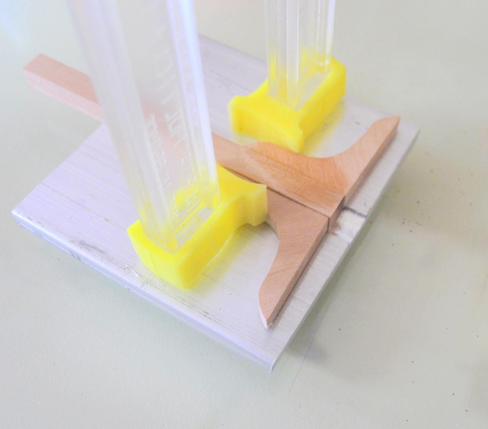
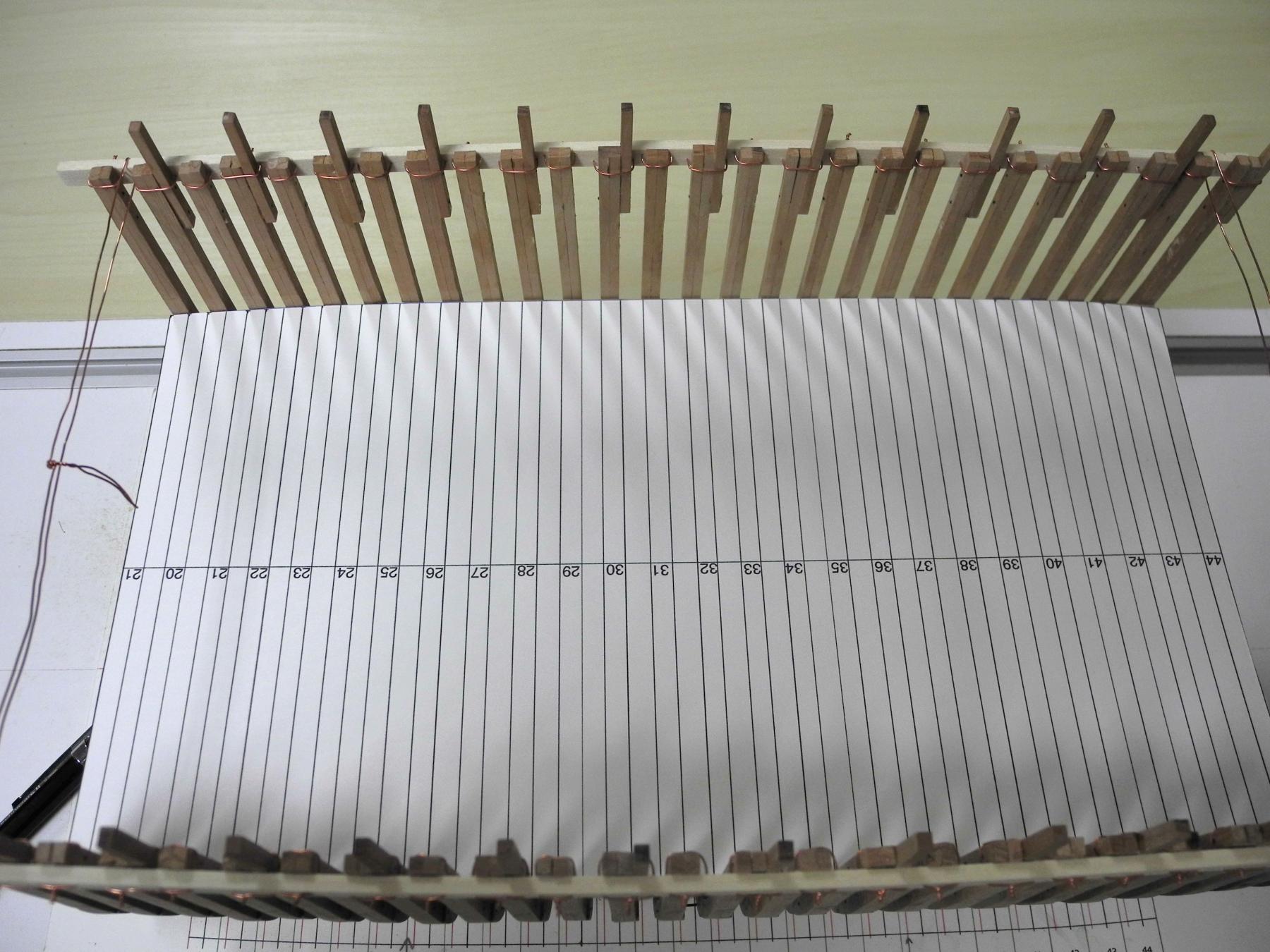
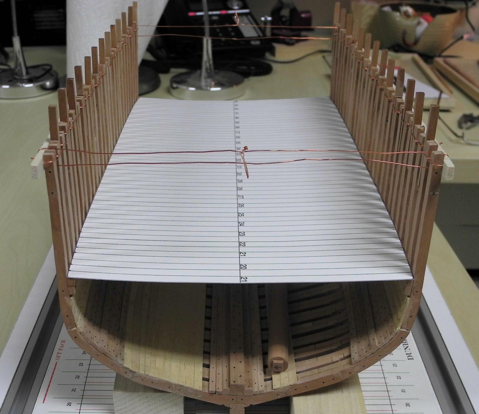
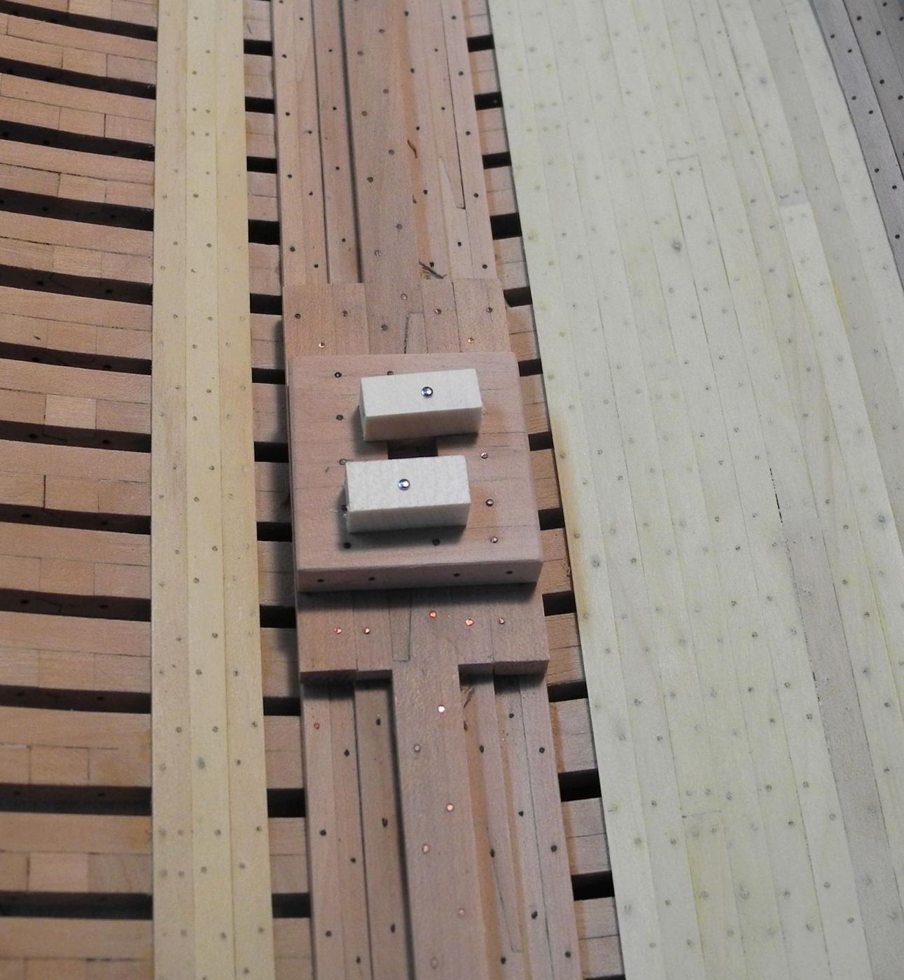
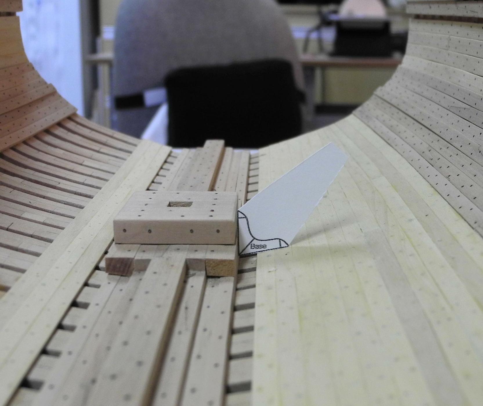
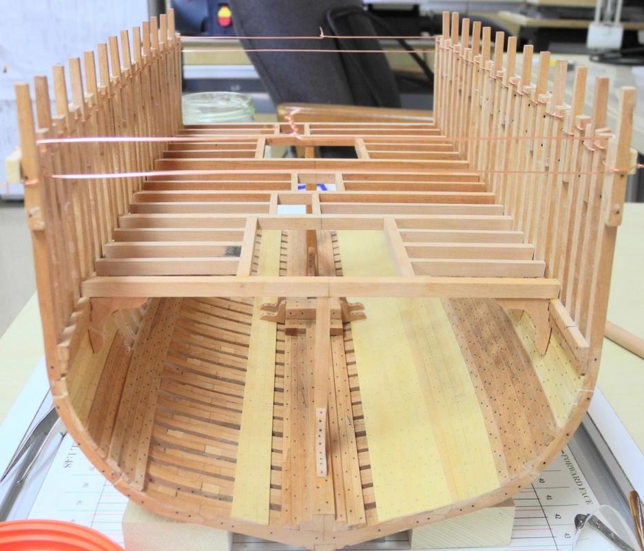
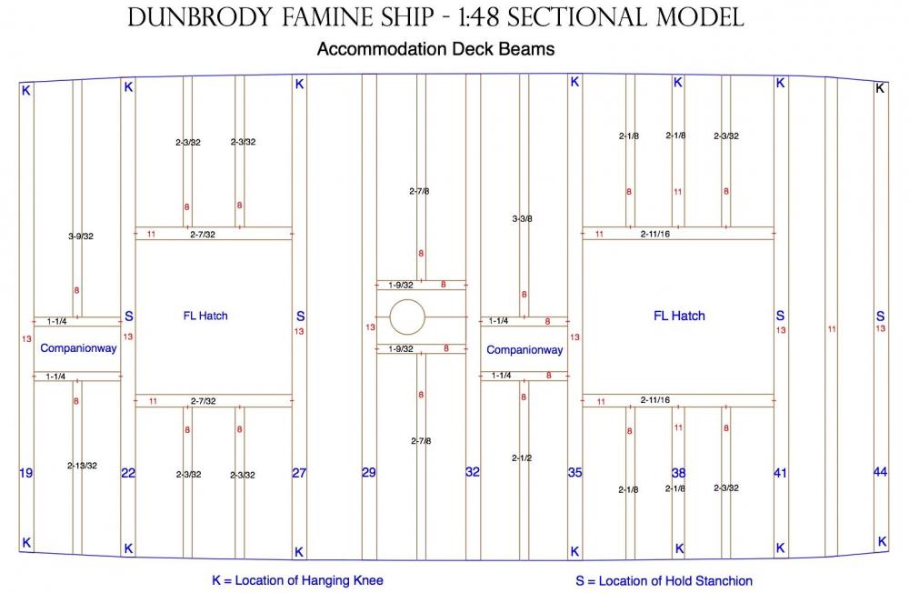
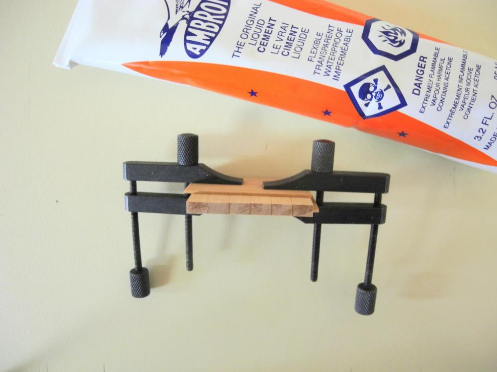
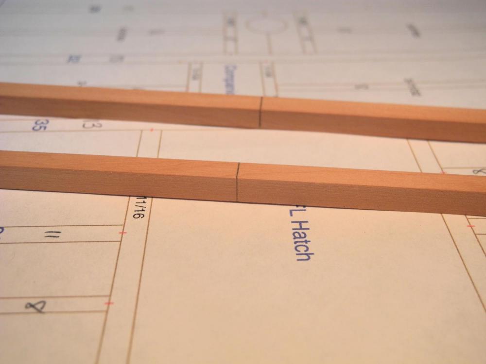
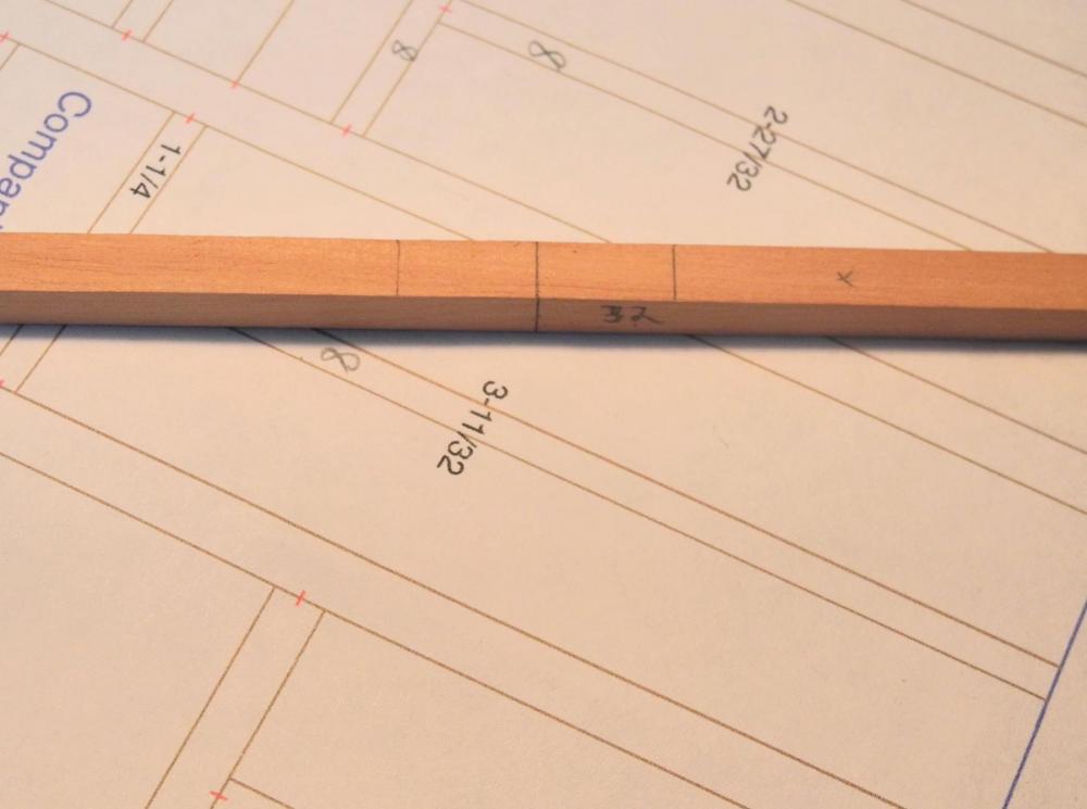
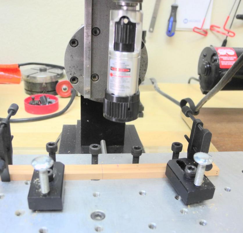
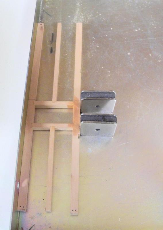
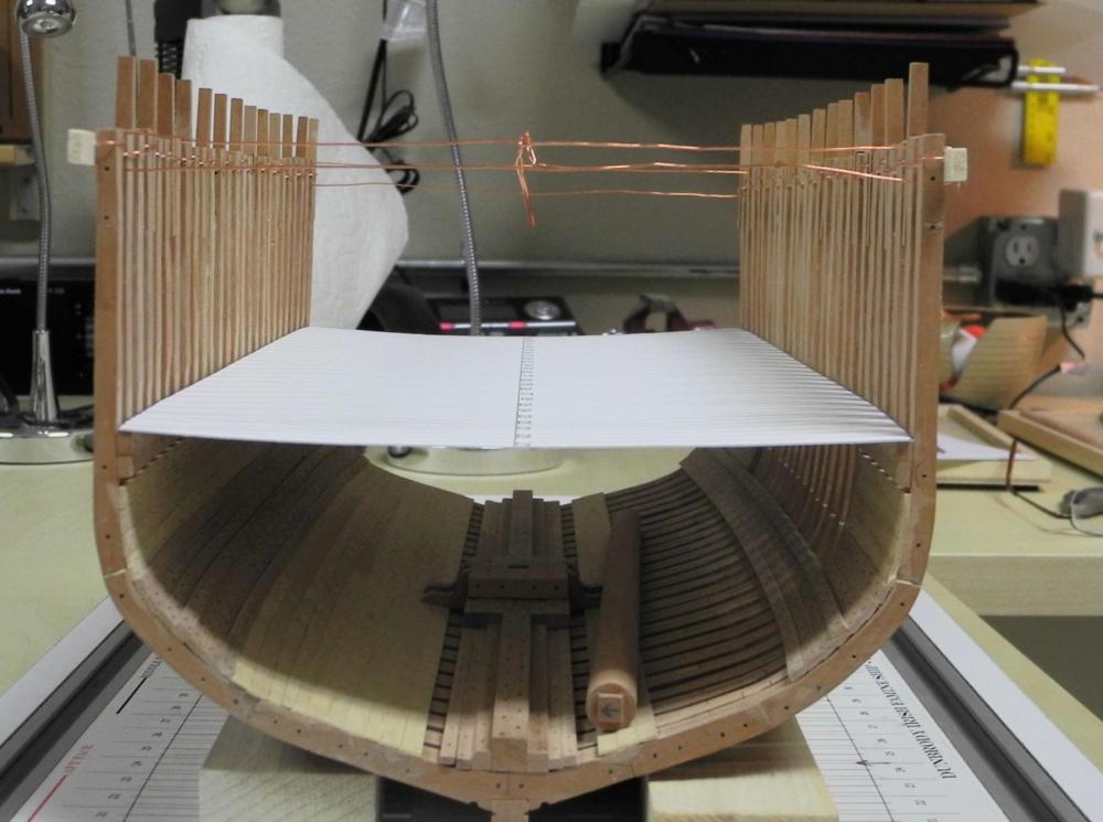
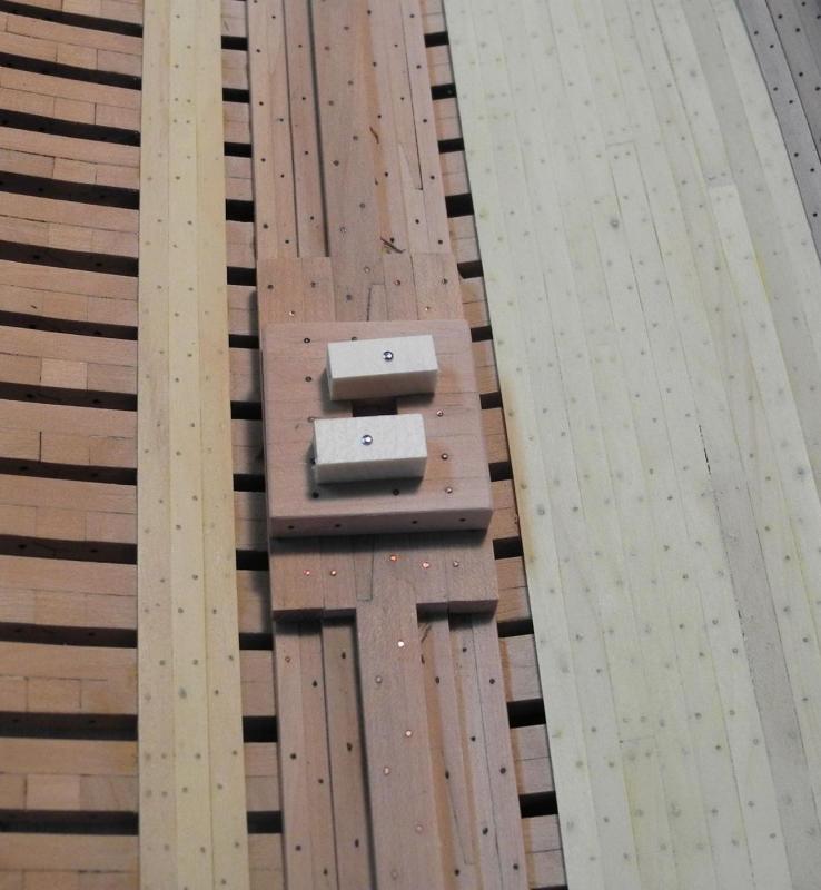
Part 26 – Accommodation Deck Beams After preparing the frame layout shown in my last post I spent some time drafting the beam configuration for the Accommodation Deck, using the Dunbrody construction plan as a guide. The Construction Plan classifies the deck beams as Main Beams and Second Beams. There are also Bulkhead Beams, but these are for the modern steel bulkheads, which won’t be included in the model. I substituted Main Beams for these. All deck beams have a moulded dimension of 10.5 inches. The sided dimension of the Main Beams is 9.75 inches, and the Second Beams are sided 8.25 inches. The small partial beams used in hatches and the mast partner are sided 6 inches. The following photo is the plan for the Accommodation Deck beams for the sectional model. The small red numbers on each beam are the actual sided dimension of each beam, expressed in 64ths, and the small black numbers on the beams is the length of that particular beam. NOTE – there are two hatches shown on the plan, both labeled FL Hatch – I have no idea what the ‘FL’ refers to, so if anyone has an idea of the meaning I’d appreciate hearing it. The Dunbrody replica ship in Ireland didn’t seem to have any hatches on the Accommodation Deck, but since the original ship was designed to carry lumber and other freight it makes sense that there are hatches. I don’t imagine that the ship’s captain worried too much about making the deck friendly for the emigrants, so I plan to make the hatch covers and associated hardware, rather than simply planking over the hatches. Before starting on the deck beams I applied wipe-on poly to the deck clamp and shelf, stringers, ceiling, and keelsons. The first step was to mill all of the required lumber. I then created each full-length deck beam, fitting the ends to the hull’s taper where necessary. I pre-drilled bolt holes in the ends of the beams. Using the bolt holes, I temporarily pinned each beam in place and marked the centerline on each beam using the setup shown in the following photo. This centerline will be a key in lining up the slots to be cut in the beams. The four headers for the two companionways in the sectional model are all the same size, and the partial beams that intersect them are all located in the center of the header, so the notches for the intersecting beams were all cut at the same time. The first step was to temporarily glue these headers together using Ambroid glue. Since the narrow sided dimension needed to be glued together, a flat piece of thin stock that spanned all four timbers was used as a base, and was part of the glue-up. Another piece of thin stock was also used on the opposite surface, but was not glued. The ‘sandwich’ that was created kept the timbers flush and level. When the milling was completed, the pieces were separated by a quick bath in acetone. The beams and partners were normally joined using a lap joint, but since only the top of the joint would be visible I decided to use a full slot for these joints, cutting the slots on the milling machine. The following photo shows the setup used. The beams needed joints as well. The centerlines marked on each beam were used to align the beams for milling. First the centerline was carried around each beam so that it was visible from each side of the beam. Every beam, header, and partner on the plan has a midline marked. The beam being worked on was then laid on the plan with the centerlines aligned, and the location of the midlines of the associated timbers was marked on the beam. The two beams that will be slotted were then clamped together with the centerlines aligned. The milling was done on a tooling plate, and I used screws inserted in the tooling plate as a ‘fence’, since these screw holes are already aligned. The first action was to align the milling head with the line for one of the slots. This was done using a laser centering device. I find this tool to be extremely useful and accurate, and worth the cost. With the head properly aligned the x-axis was locked in place, the laser was replaced with an end-mill, and the slot was milled. All of the beams and associated timbers were cut to size and the appropriate slots cut. All pieces were then dry-fit on a copy of the plan. After seeing Glenn’s work on the Heroine deck I was hoping to glue the hatch assemblies together off the model and to then install them as ‘modules’, but the slight tumble-home prevented me from doing this. I was able, though, to make some ‘sub-assemblies’ off the model. Seven of the deck beams each have a pair of hanging knees. Since the knee will cross the deck shelf, deck clamp, and bilge ceiling – all of different moulded dimensions – creating these knees was fairly complicated (and error-prone). There are also 4 hold stanchions (pillars) in the model – these were more straight-forward. The stanchion knees are held in place using a restorer’s clamp (from Lee Valley). The moulded dimension of the knees is smaller than that of the stanchion, so I needed a way to ensure that the knees were correctly centered. I milled a piece of aluminum stock so that the groove is approximately the same width as the stanchion, and the depth is one-half of the difference between the stanchion size and the knee size. – the assembly is resting on the jig in the above photo. The following photos show the current status of the model – the forward hatch assembly is in place, including three pairs of hanging knees and two hold stanchions. Thanks everyone for following, and for the comments and ‘Likes’ – all are much appreciated.


- 649 replies
-
- 19
-
-
- dunbrody
- famine ship
- (and 2 more)
-
Welcome back, Ed (and happy Father's Day). I've been suffering YA withdrawal and looking forward to your next update.
- 3,618 replies
-
- 4
-
-
- young america
- clipper
- (and 1 more)
-
Beautiful work Glenn. Can you give us a few details on how you created the profile for the nosing you show in photo #3, and how you cut that perfect hole for the post shown in the same photo?
-
Hi Neal I agree that Box and Pear are the traditional hardwoods used. However, there are some other alternatives that are very similar but more readily available and much less expensive. Castello and Pau Marfin (also know as Guatambu) are good substitutes for Box, and Madrone is very similar to Pear. I've also used African Pear, which is somewhat darker than European Pear but has a nice tight grain. Most of these woods can be found in stores such as Woodworkers Source or from lumber suppliers online. I can send you a PM with my wood sources if you'd like. Hope this helps.
-
LOL - I just noticed a misprint on the layout - I have two frame #21's instead of a #19!
- 649 replies
-
- 7
-
-
- dunbrody
- famine ship
- (and 2 more)
-
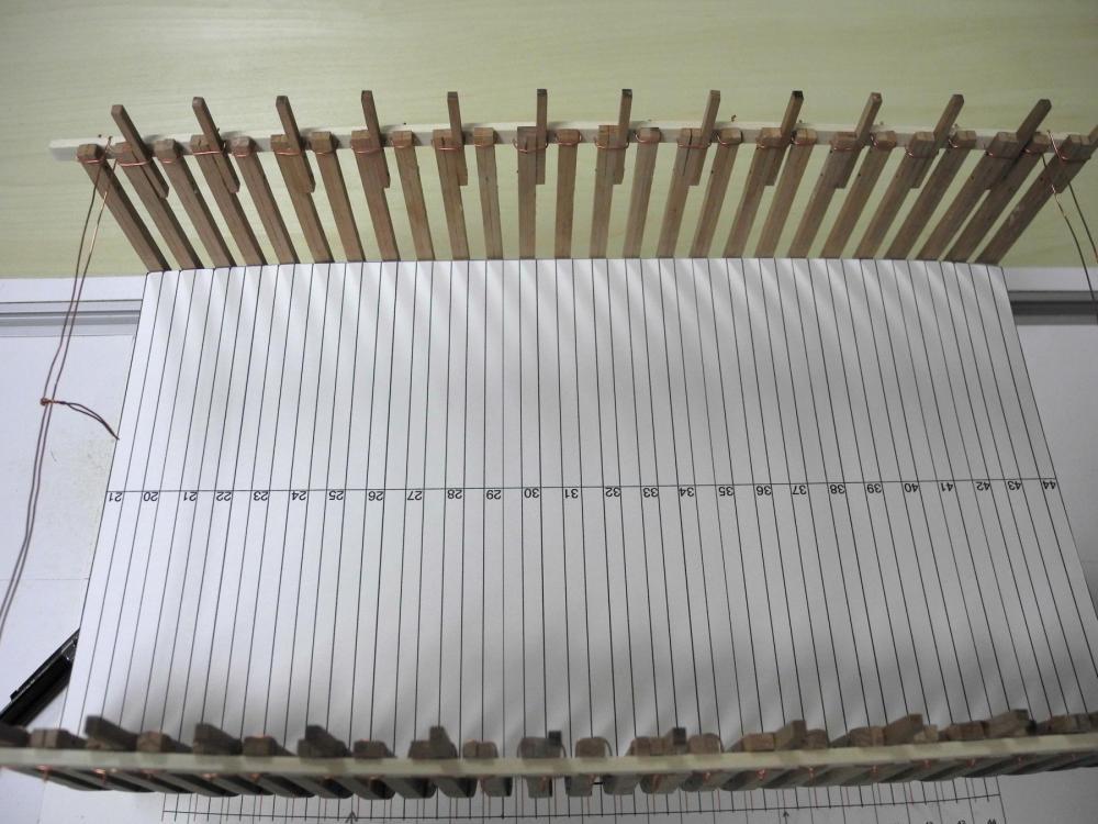
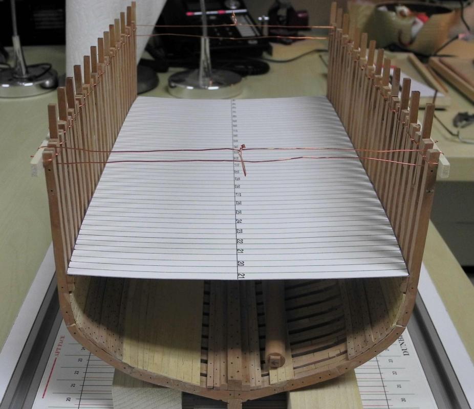
Part 26 – Planning The Accommodation Deck In thinking about drafting the Accommodation Deck beam structure, one of the things that concerned me was having a good foundation for the drafting. What I mean by that is having an accurate layout of the framing so that the beams can be laid out accurately. Even though the layout of the frames as I originally drafted in CAD is precise (because of CAD) I also knew that there were a lot of errors that crept in during the build and installation of the frames. I needed a way to make sure that the plans for the Accommodation Deck took these errors into account. I decided the best way to do that was to measure all of the frames and the spacing between the frames at the level of the Accommodation Deck, and to use these measurements for planning the build of the deck structure. I measured the span of each of the frames at their fore and aft faces, adjacent to the top surface of the deck shelf. I also measured the sided dimension of each frame at the same location, and the spaces between each of the frames at that location. I used these measurements to draw a layout of the actual model at the level of the Accommodation Deck, and I’m very pleased with the results – this will form a good foundation for accurately laying out all of the beams for the deck. I printed the layout on a heavy card stock and laid it in place to see how it worked out. I had to make a few adjustments to account for some errors in measuring, but after a couple of iterations I now have a workable base for planning the beams. So now I’ll start drafting the beams for the deck, and I should be able to get back to making some more wood dust fairly quickly. Thanks everyone!
- 649 replies
-
- 20
-
-
- dunbrody
- famine ship
- (and 2 more)
-
Hi Glenn - that's one of the great things about build logs - we get to see new (to us, anyway) ways to do things. Your Heroine build has given me lots to think about, and right now I'm thinking of trying your approach for building the deck structure.
- 649 replies
-
- 4
-
-
- dunbrody
- famine ship
- (and 2 more)
-
Thanks Patrick. I guess my life in information technology conditioned me to details. I learned the process for making spars in a seminar by David Antscherl, and enjoy making masts and yards that way.
- 649 replies
-
- 6
-
-
- dunbrody
- famine ship
- (and 2 more)
-
Hi Brian - the decks will look great - I like your decision to use a quality wood and leave it natural.
-
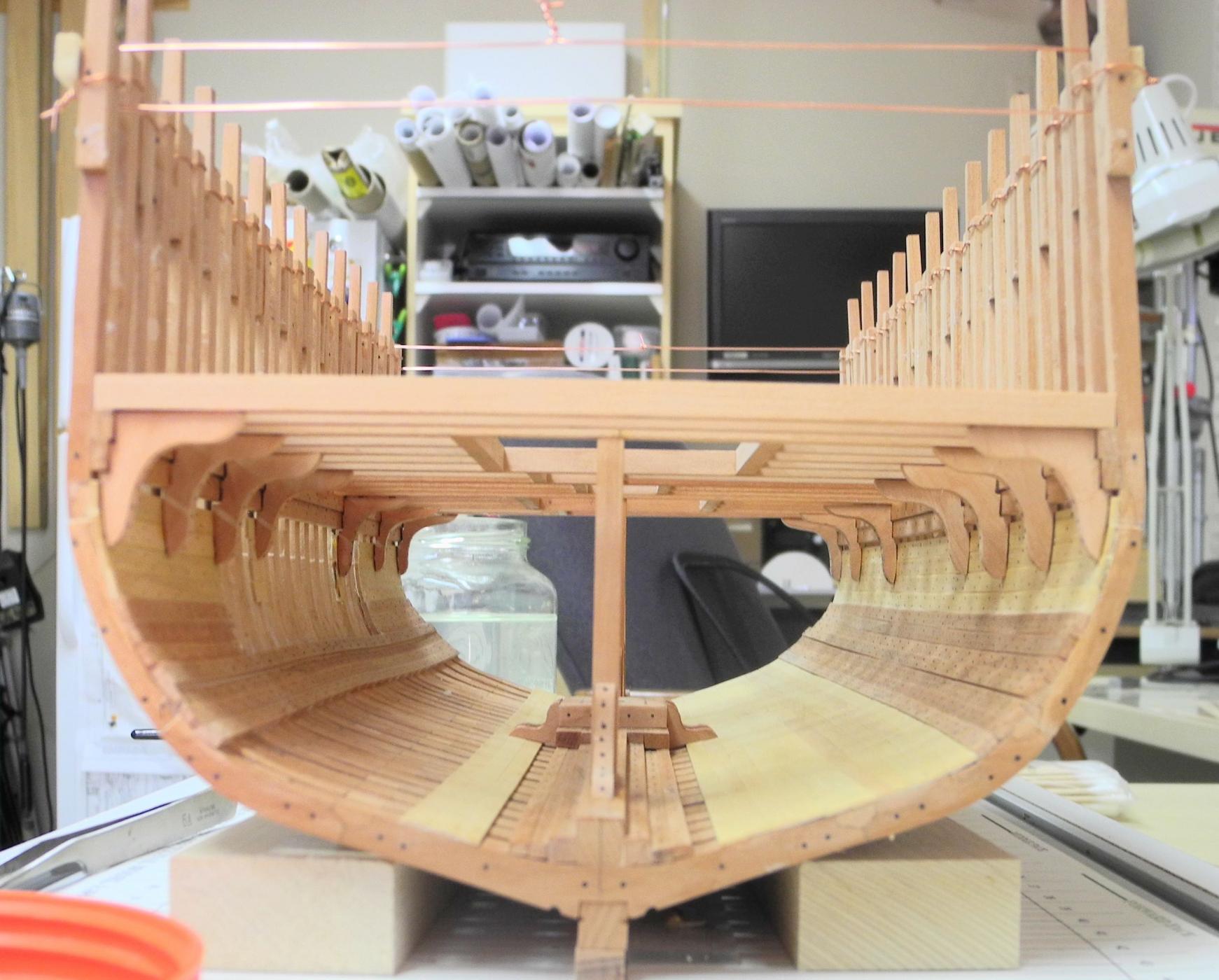
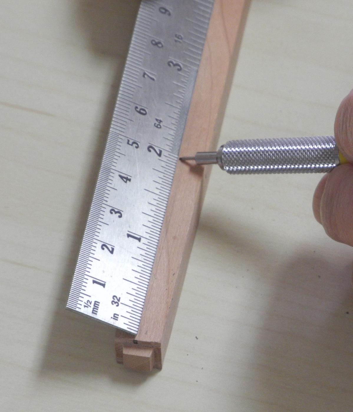
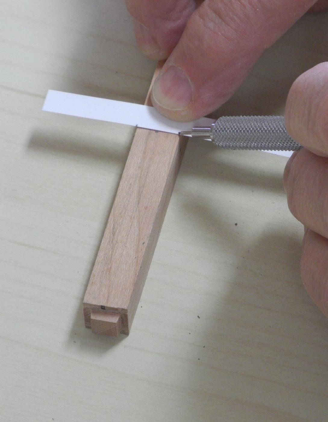
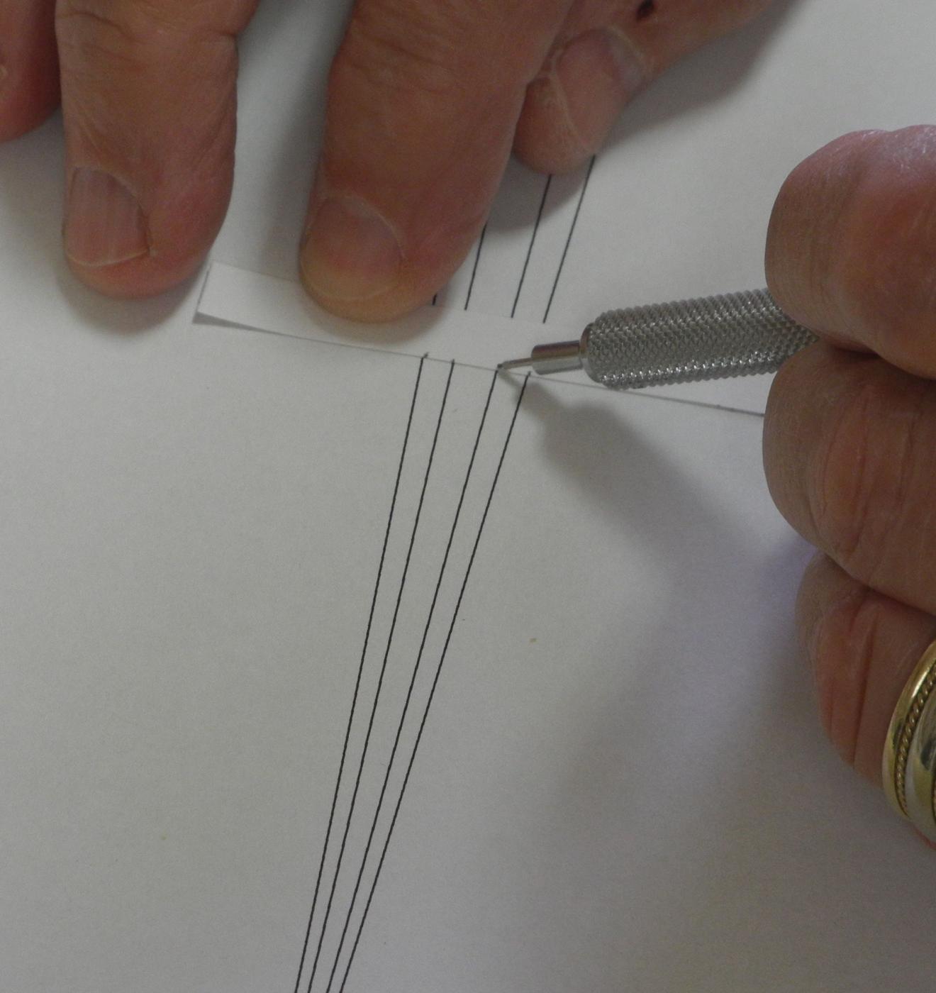
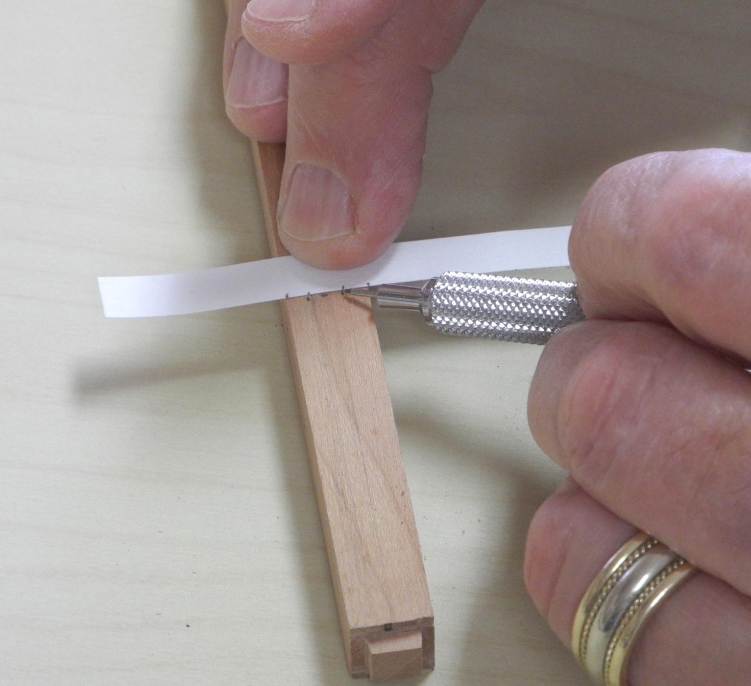
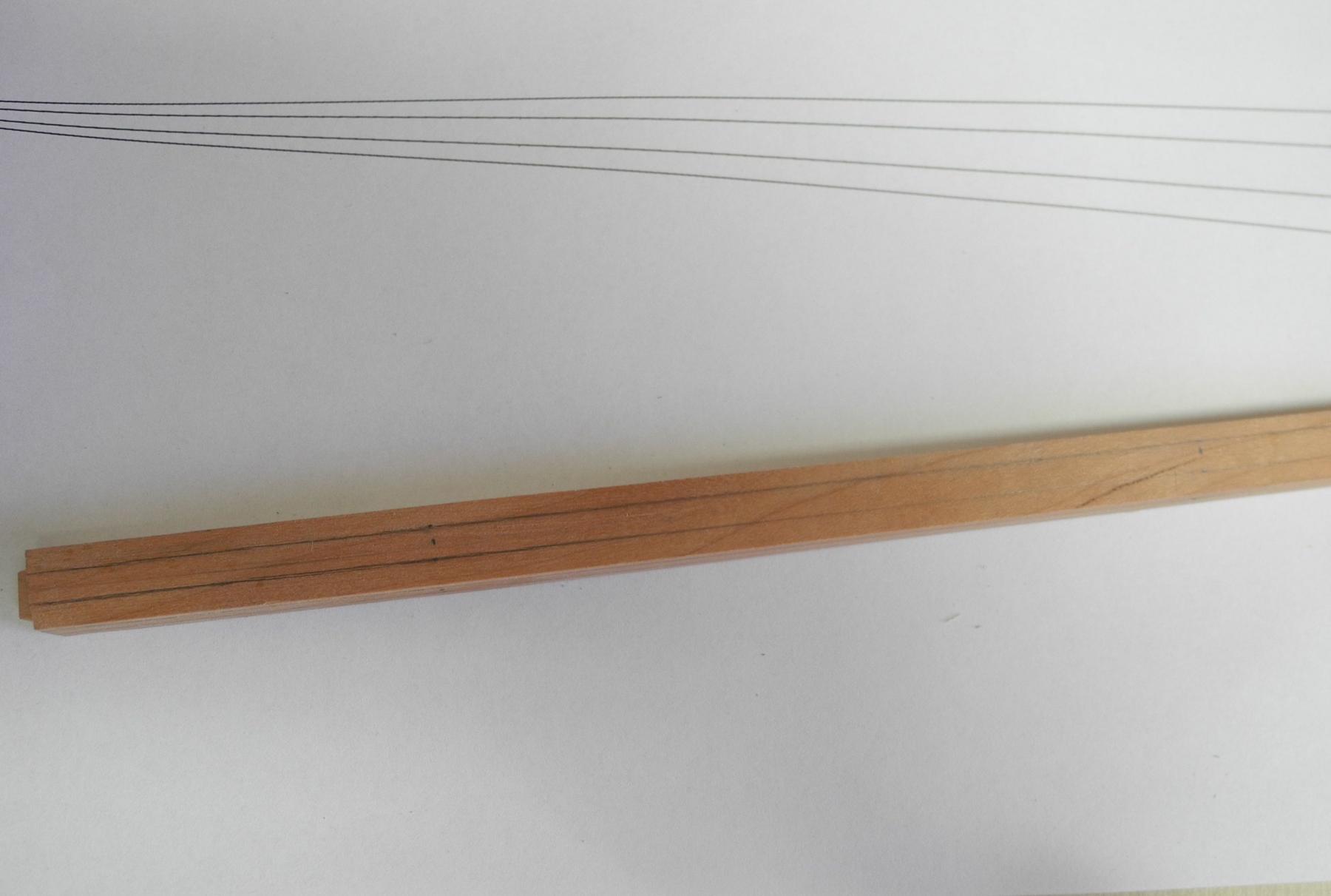
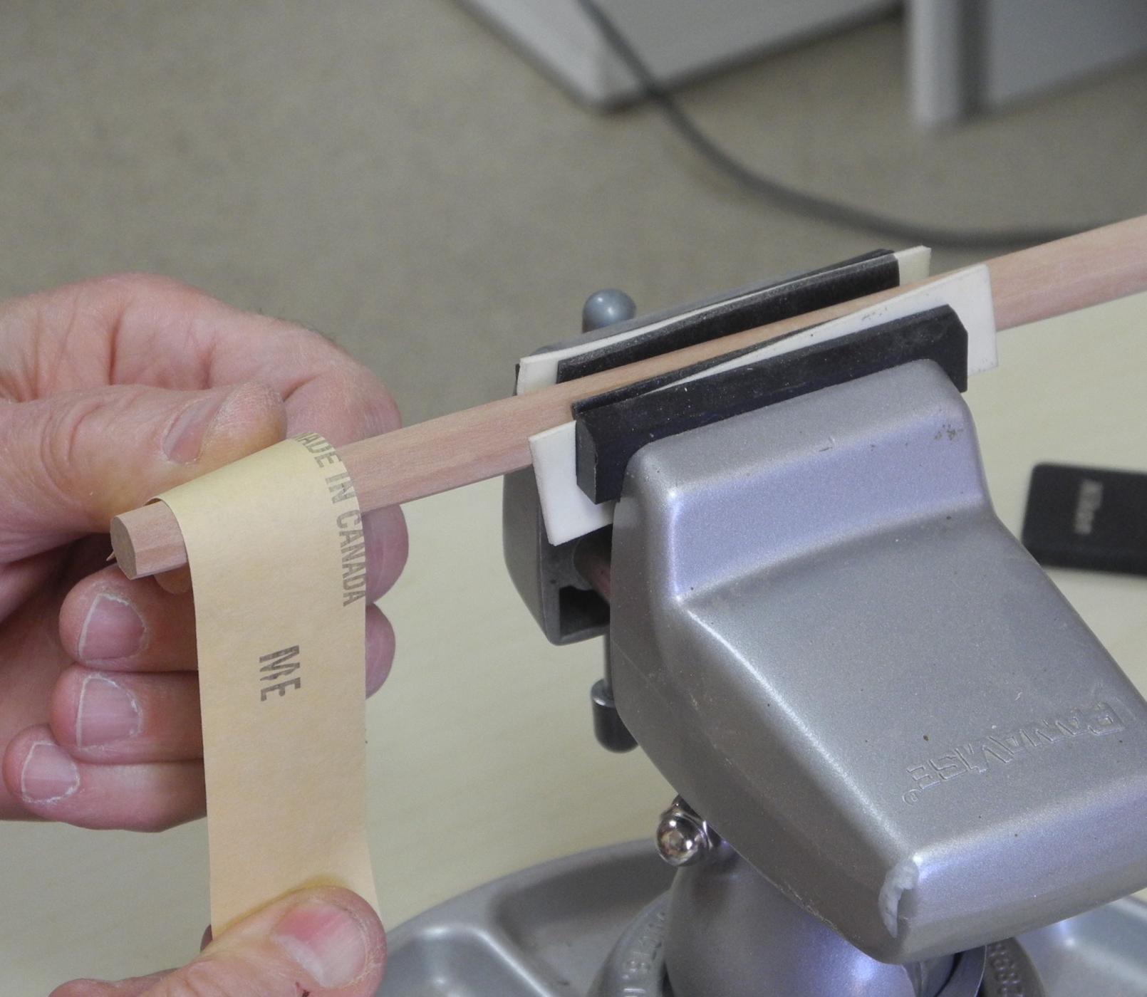
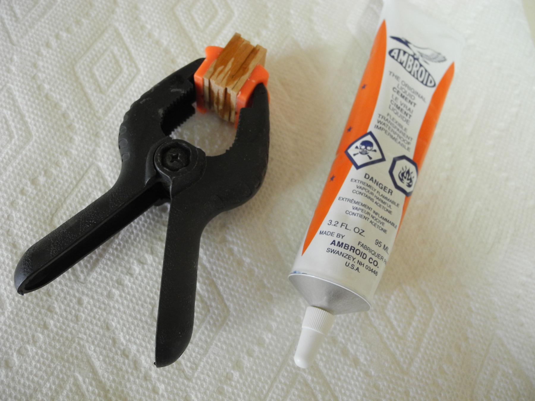
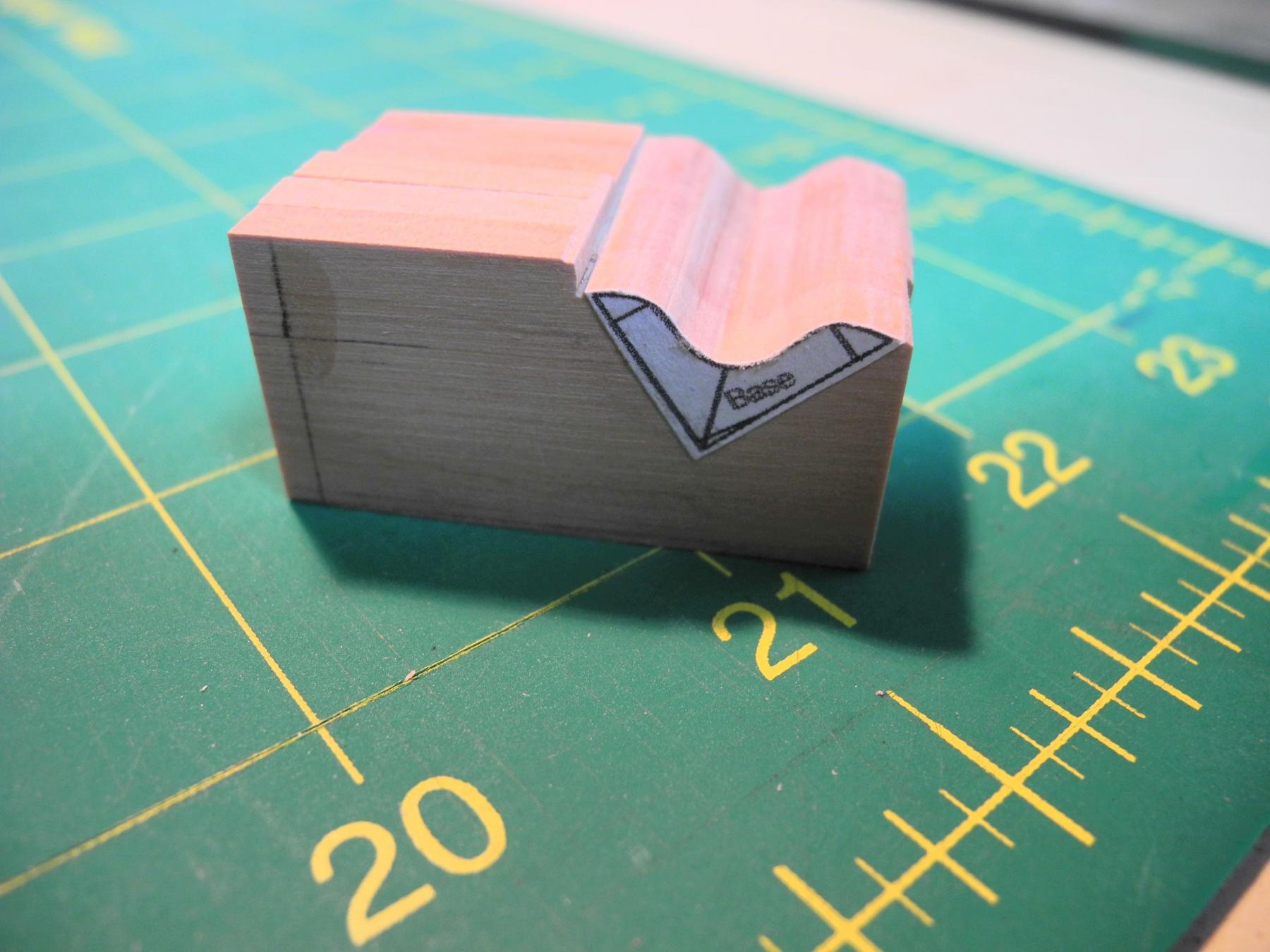
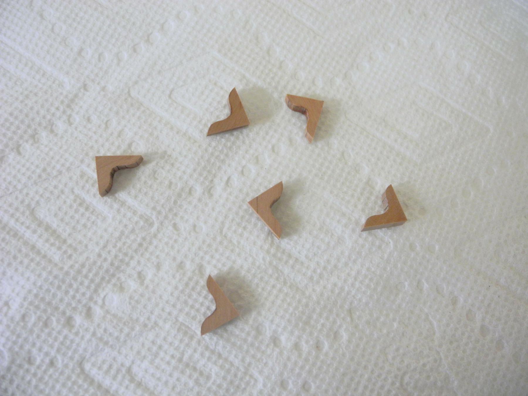
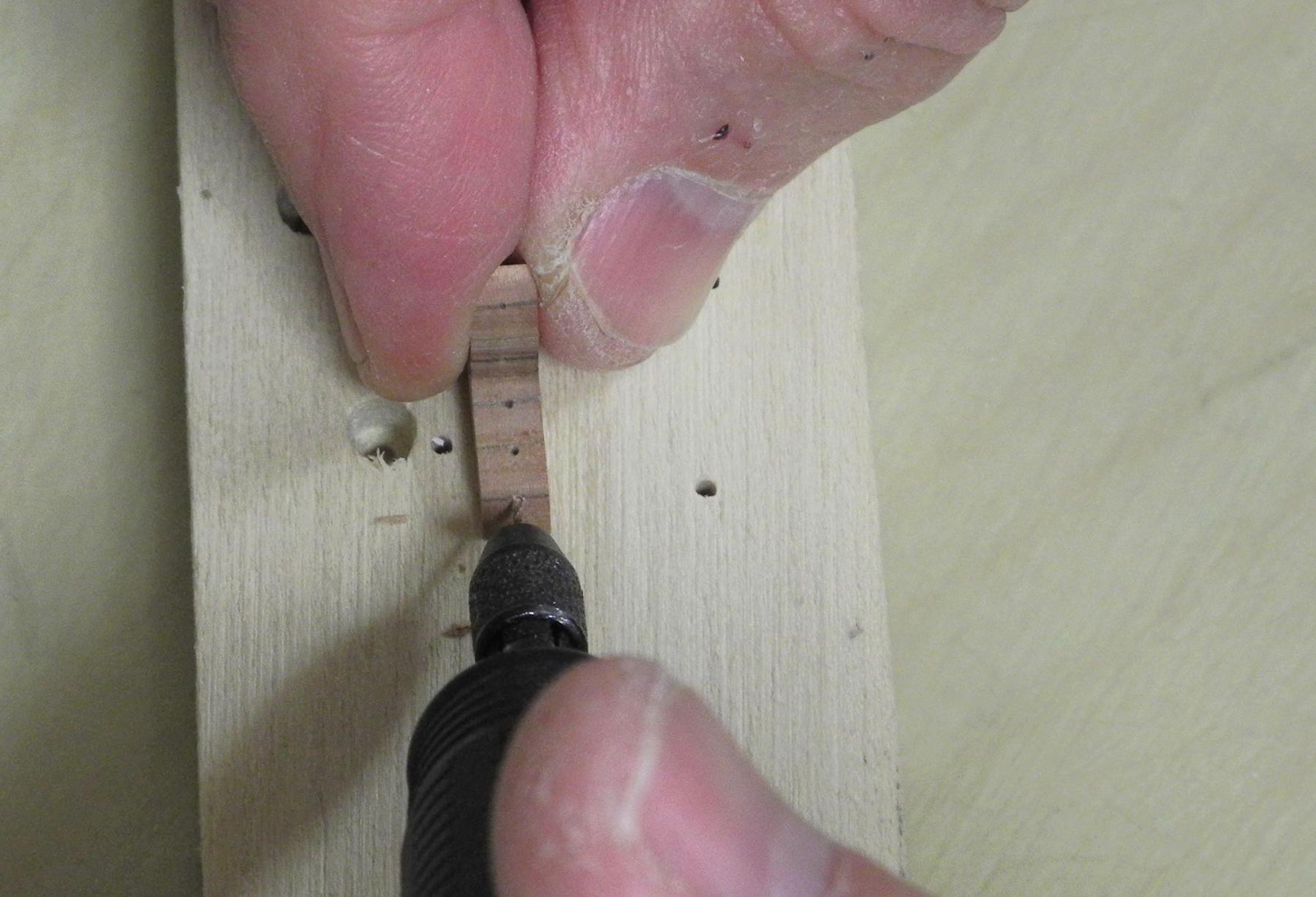
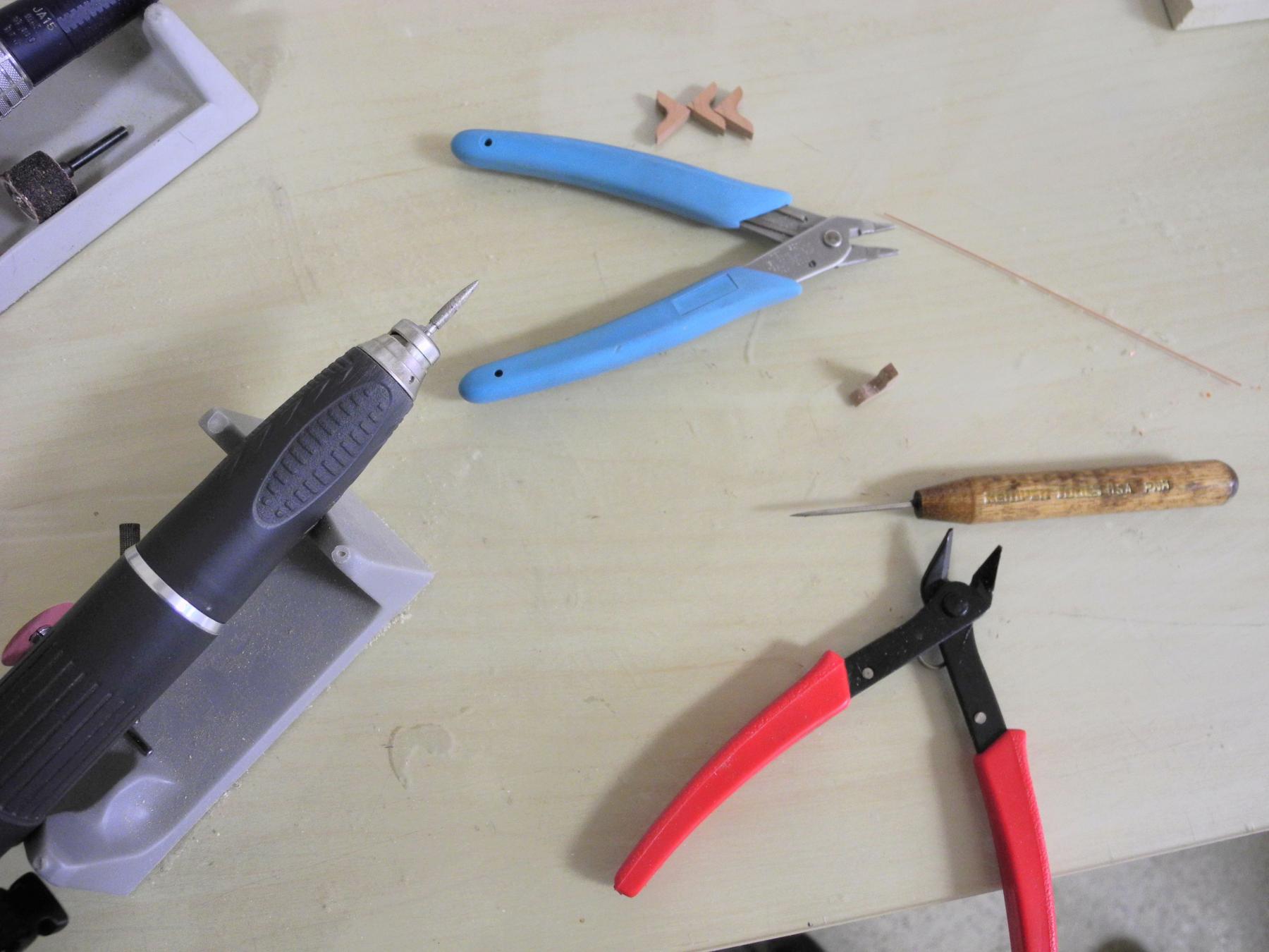
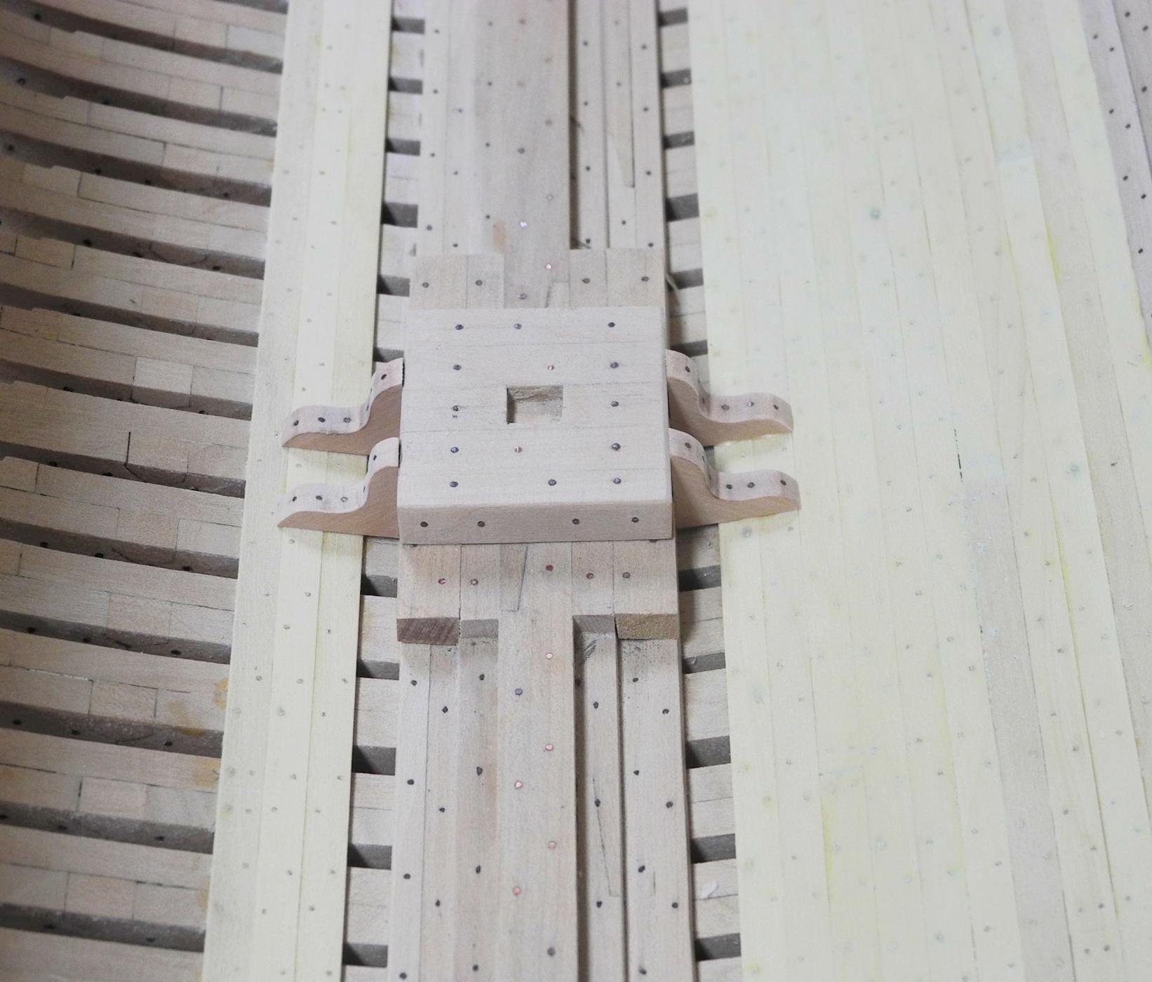
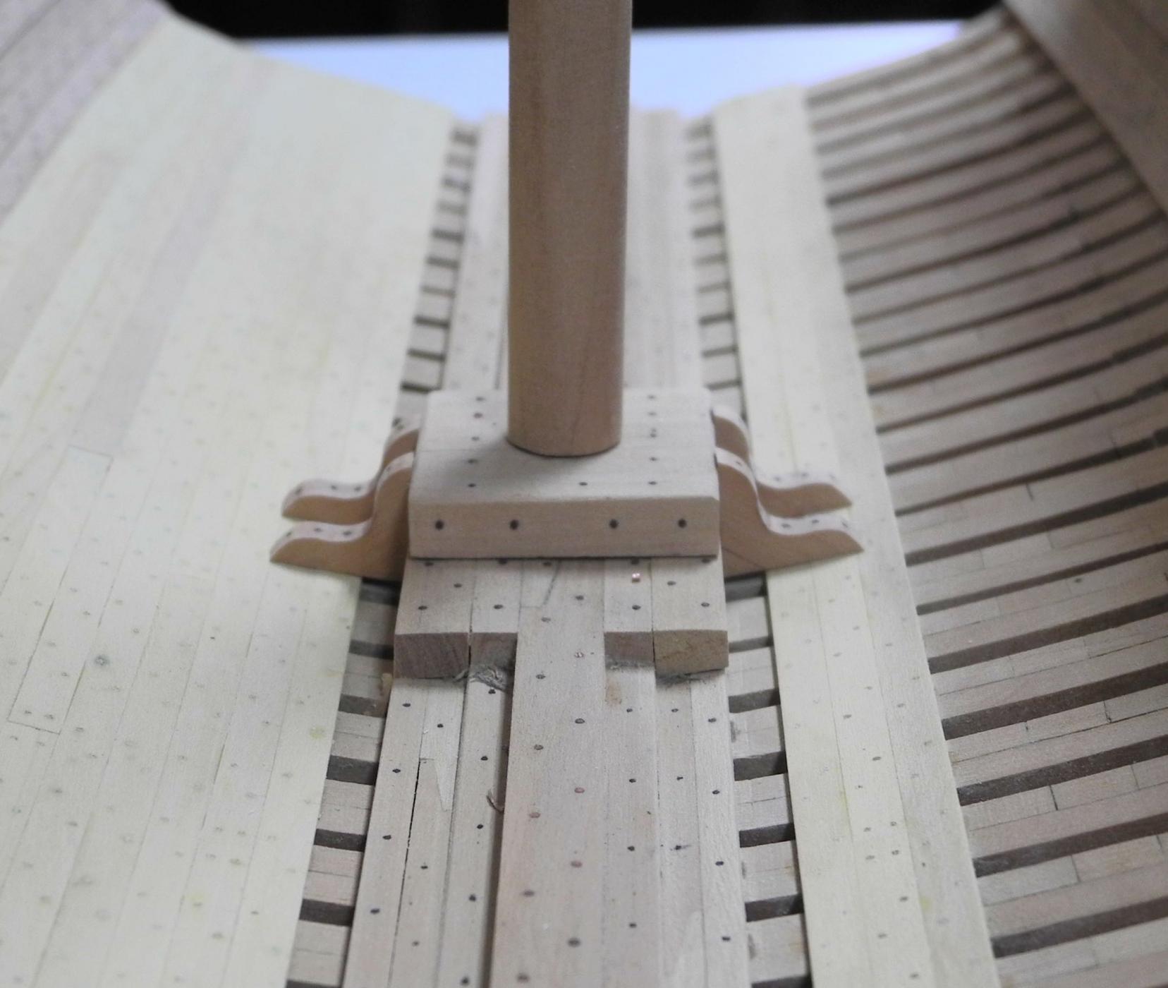
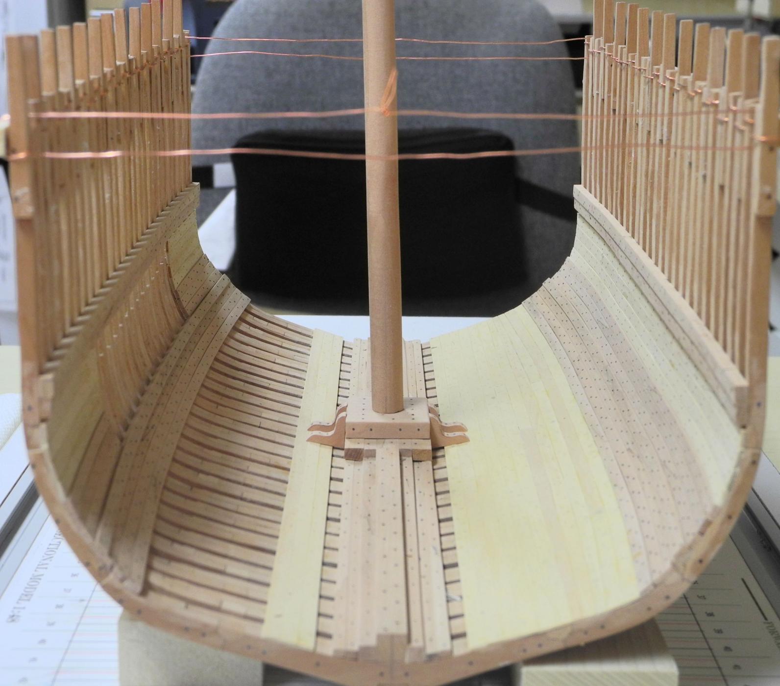
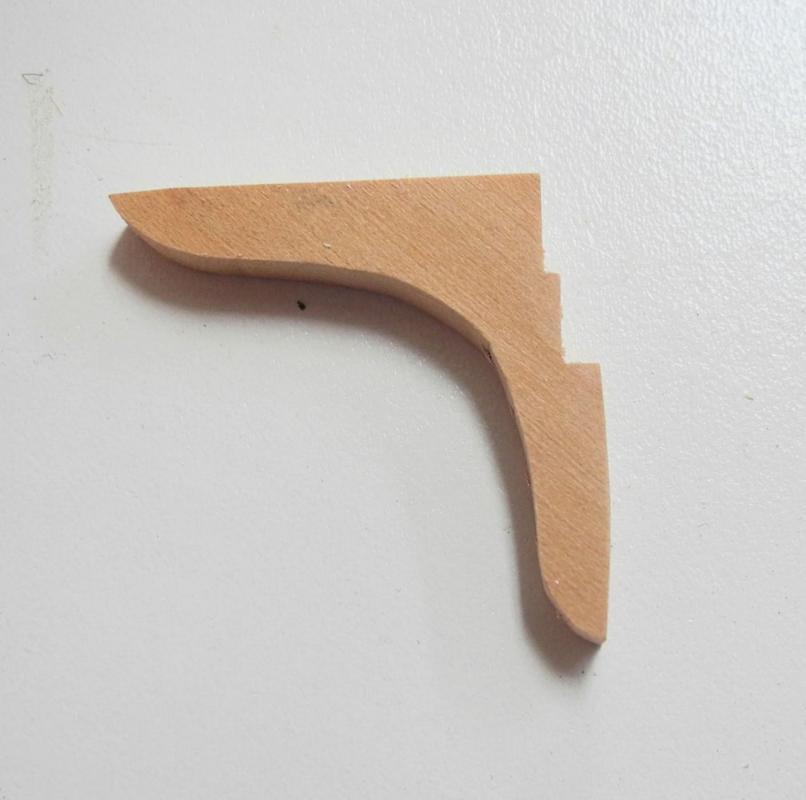
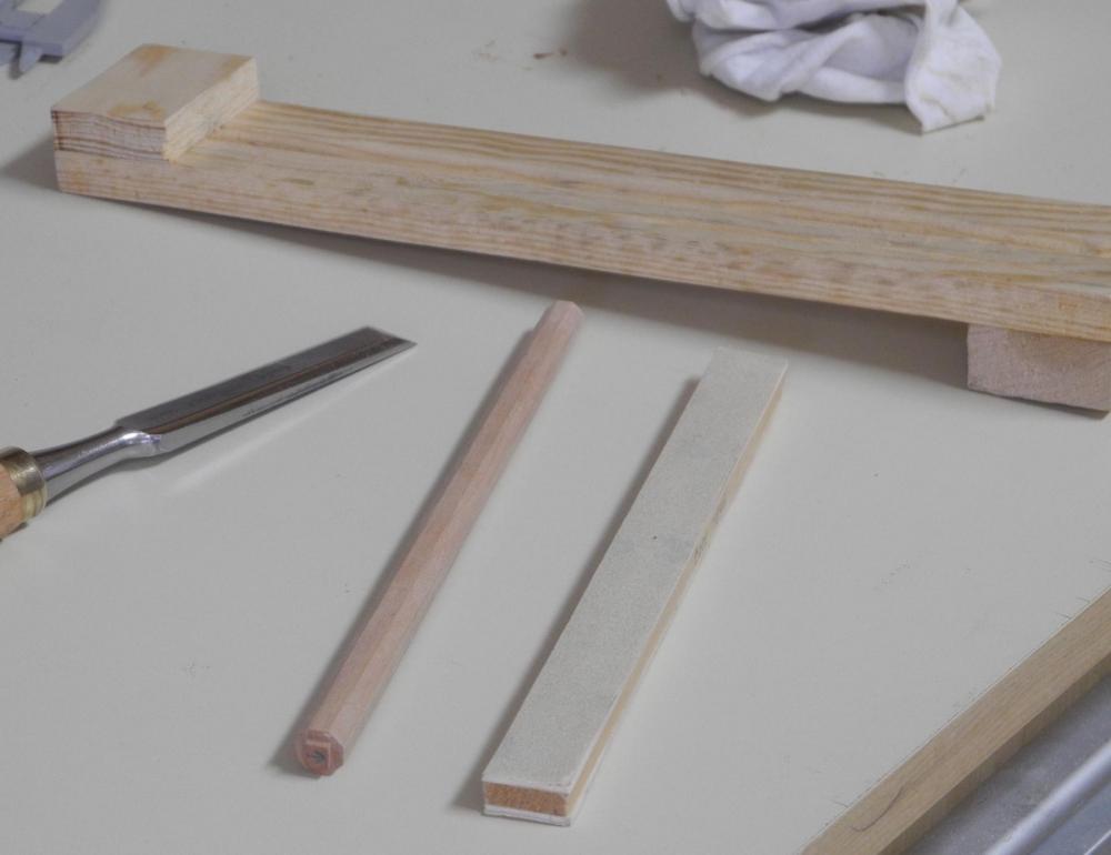
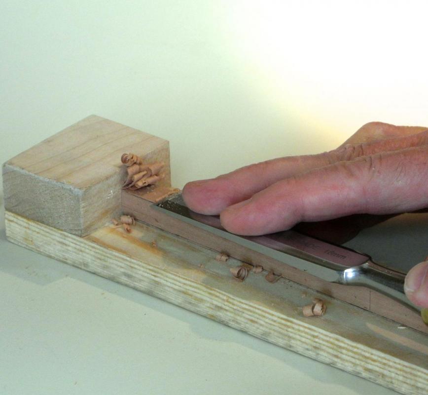
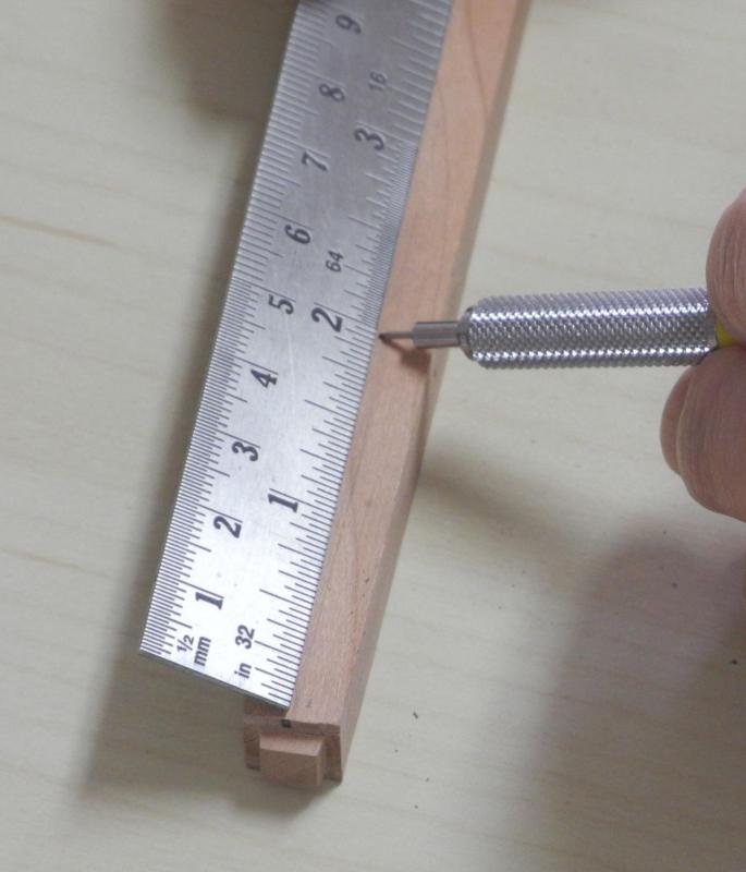
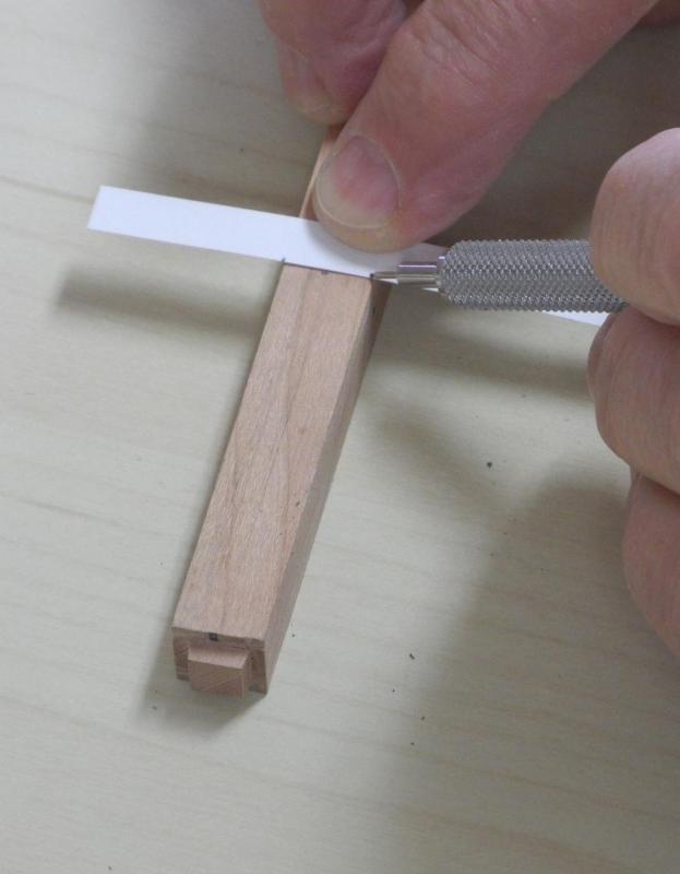
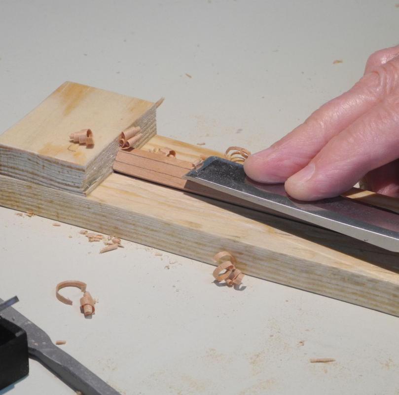
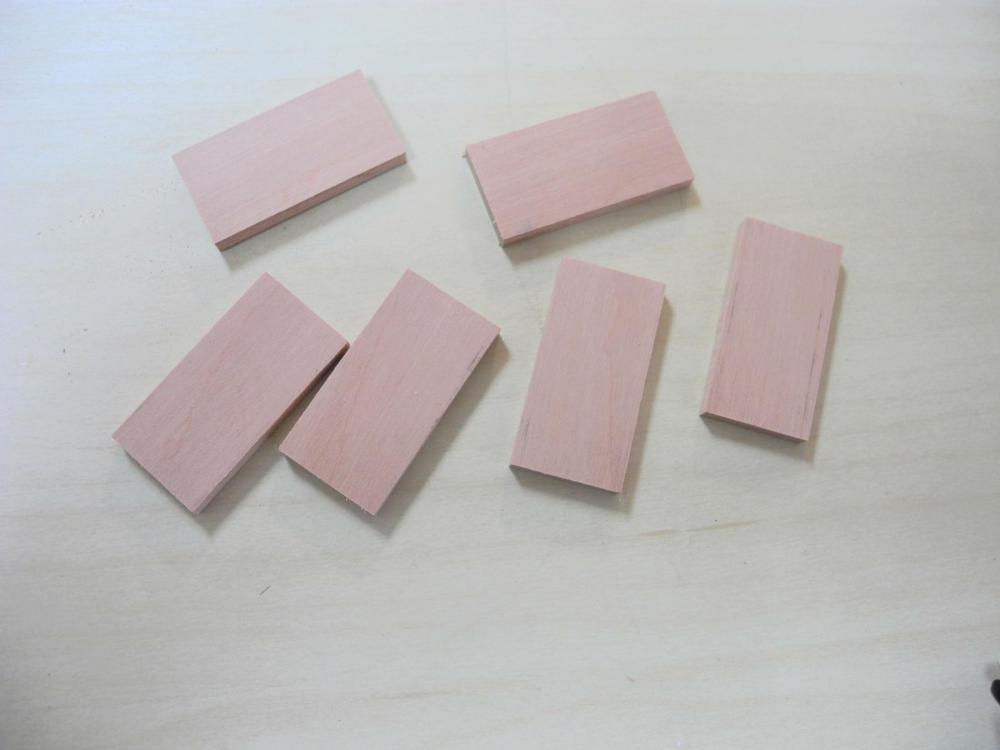
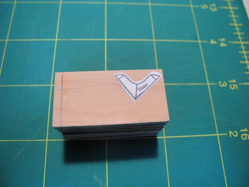
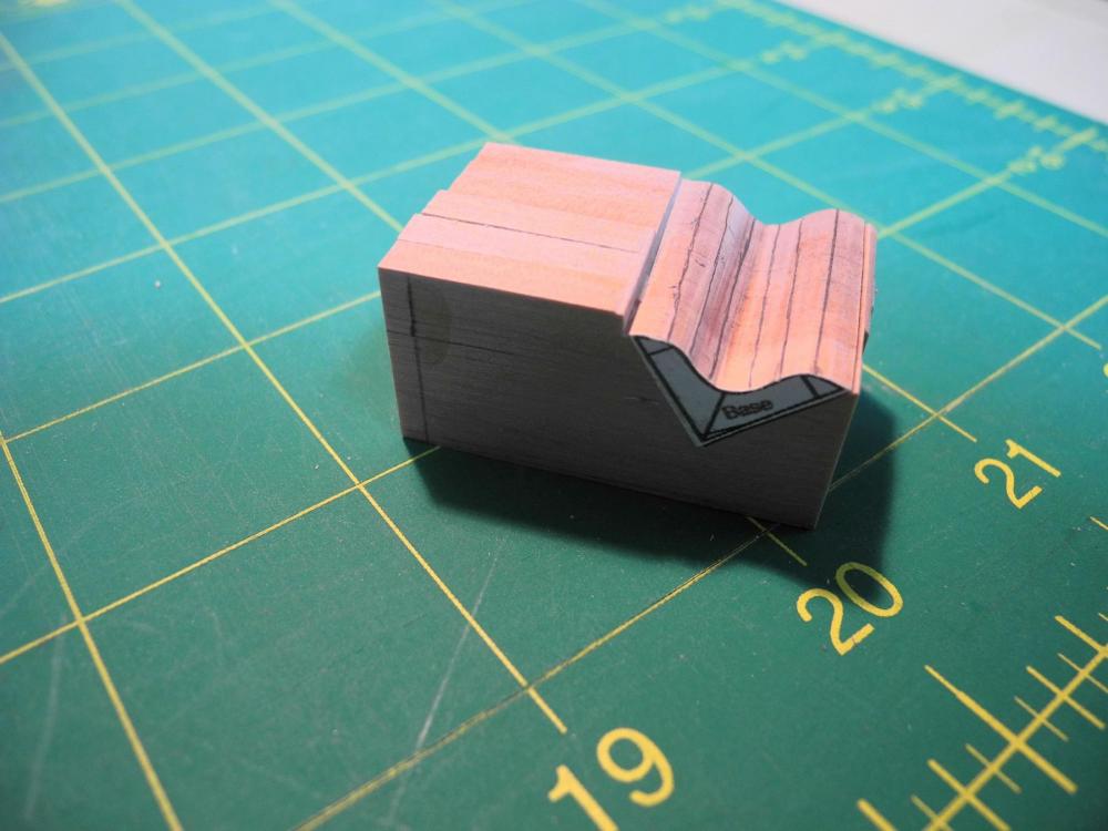
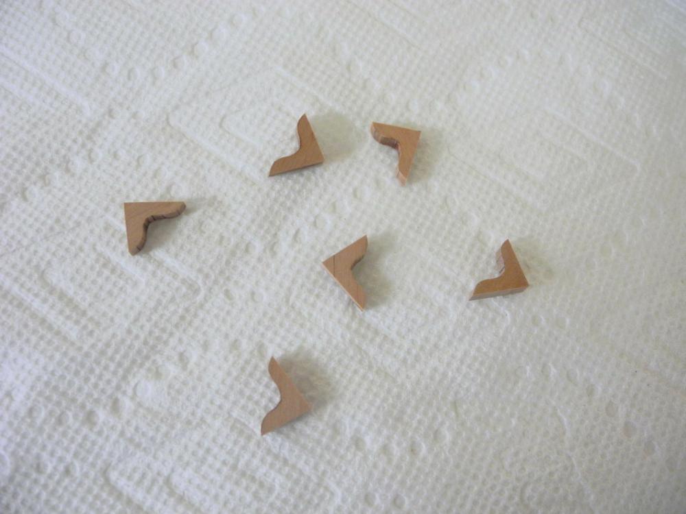
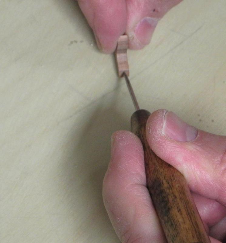
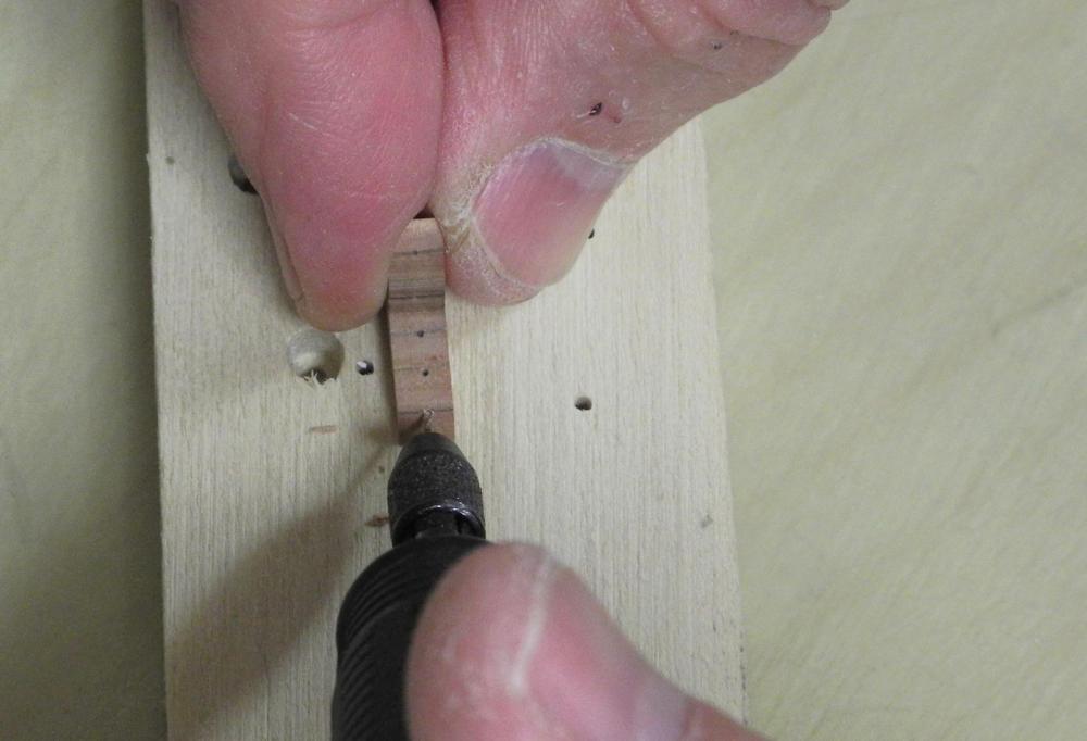
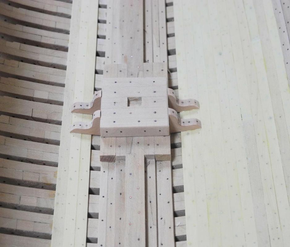
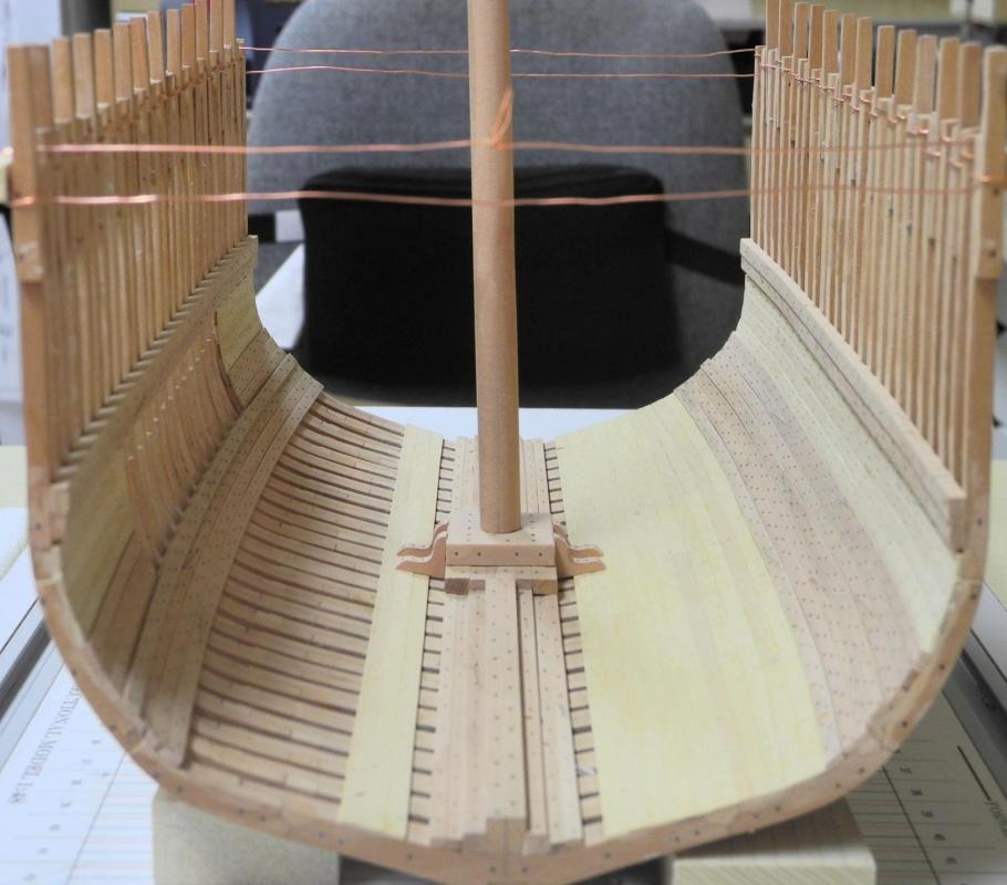
Part 25 – Mast and Mast Step Cont’d Making the mast out of square stock consists of first cutting the mast to the proper taper and then making the mast octagonal. Once the mast is octagonal it can be sanded to the final round shape. The tools used for shaping the mast are a good paring chisel (kept sharp), a jig for holding the stock steady while paring it, and a good sanding stick for finishing off the cuts. The jig has a flat surface on one side and a v-groove on the other. The mast stub for Dunbrody has a very slight taper, starting at 19.5 inches diameter at the foot, tapering to approximately 18 inches at the height of the main deck, and then continuing that taper to the end of the stub (I haven’t yet decided how high from the deck the stub will end, so I made it fairly generous). Once the taper is marked on the mast, it is placed on the flat side of the jig and pared to the marks. Then a 7-10-7 fan is used to mark the octagonal lines on the mast stock. I marked the mast at 2 inch increments and carried these marks around all sides using a square. Then the dimension of the mast at each of these points is marked on a tic strip The tic strip is then moved to the appropriate spot on the 7-10-7 fan and the inner lines are marked on the tic strip… ..and the marks are transferred to the mast. Once all these points have all been transferred to the mast on all sides the points are joined by continuous lines drawn on the mast. The mast is placed in the jig with a corner in the v-groove of the jig to hold the stock steady, and the corners of the mast are pared off to the lines, forming the octagonal mast. 9 This octagonal mast is then sanded to a round shape. After the mast was completed, the platform of the mast step was drilled for bolts. Two of the bolt holes were left open for pinning and the rest of the holes were filled with copper wire for simulated bolts. The platform was then glued and pinned in place. The last step is making knees for the Mast Step. These knees help to distribute the weight of the mast across the frames and are bolted through several of the floor ceiling planks. The first step is to create a CAD drawing of the knees and to test it for a good shape and fit. A tab was left on the drawing of the knee for handling, since the knee is only about ½” on each axis. I decided to use oversized blanks of 5/32” stock for the knees to allow me to grip them while cutting them out on the scroll saw. The blanks were glued together using Ambroid glue and clamped for drying. After the blank set was dry the drawing of the knee was glued to the stack of blanks using a glue stick. The first cut was the shape of the curve of the knee. While the blanks were still glued as a set I marked the approximate location of the bolts, so that the knees would appear to be consistently bolted. The remaining straight cuts were made, and the knees were separated by a quick bath in acetone (in a closed container). Pilot holes were marked on each knee using a small awl … …and the bolt holes were drilled in the knees. The work-hardened copper wire was 20 gauge, and the drill used was a #70. The fit was tight enough that no glue was required to keep the wire in place. I simply grabbed the wire near its end and pushed it into the hole as far as it would go, then nipped off the end of the wire. The last step was to smooth the end of the bolts using a diamond bit in the rotary tool. With the knees glued in place the mast step is completed, and all work in the hold is finished. The next step is to begin working on the beams, stanchions, and knees for the Accommodation Deck. Some drafting is required, so it will be several days before I have any more progress to post. In the meantime, thanks everyone for following, and for the “Likes” and comments.


- 649 replies
-
- 28
-
-
- dunbrody
- famine ship
- (and 2 more)
-
Thanks Druxey. I actually tapered the tenon on the first mast that I made but I decided that, given the shallow depth of the tenon, it would fit more securely if I left the sides straight.
- 649 replies
-
- 3
-
-
- dunbrody
- famine ship
- (and 2 more)