Mahuna
-
Posts
1,504 -
Joined
-
Last visited
Content Type
Profiles
Forums
Gallery
Events
Everything posted by Mahuna
-
 Thanks Bob. It was great seeing you on Wednesday, and seeing Pequot in person - beautiful work! It's even better in person than in the photos.
- 649 replies
-
- 4
-

-
- dunbrody
- famine ship
- (and 2 more)
-
Thanks Carl - I made frequent checks using a digital caliper. Thanks Ed.
- 649 replies
-
- 4
-
-
- dunbrody
- famine ship
- (and 2 more)
-
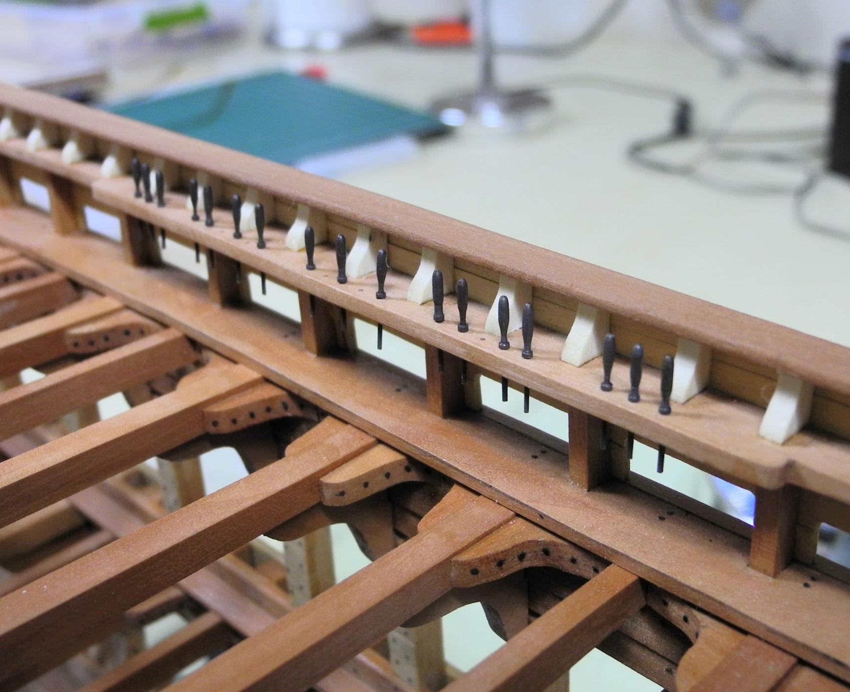
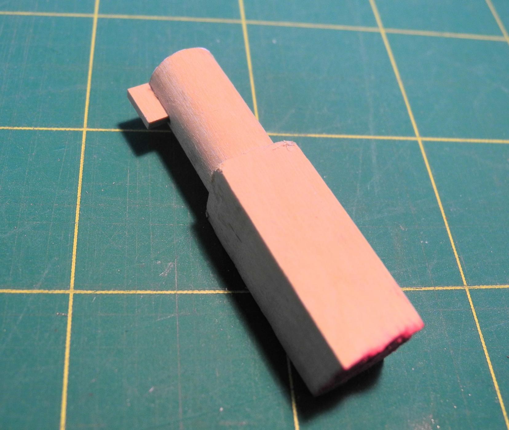
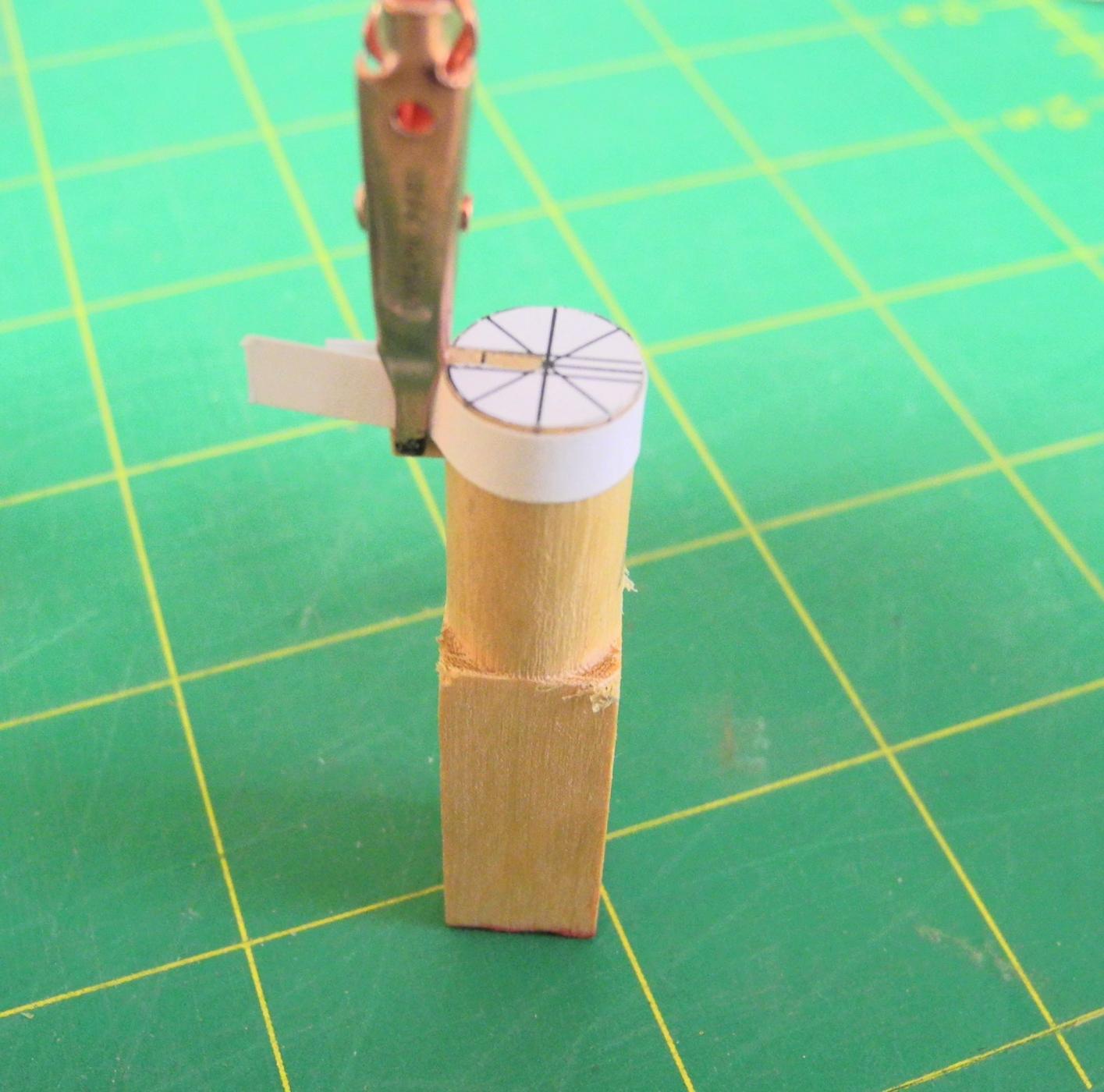
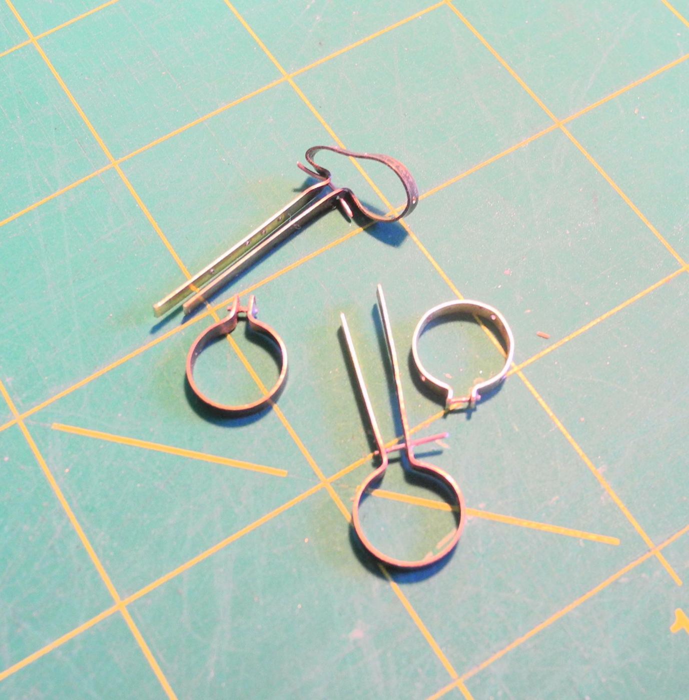
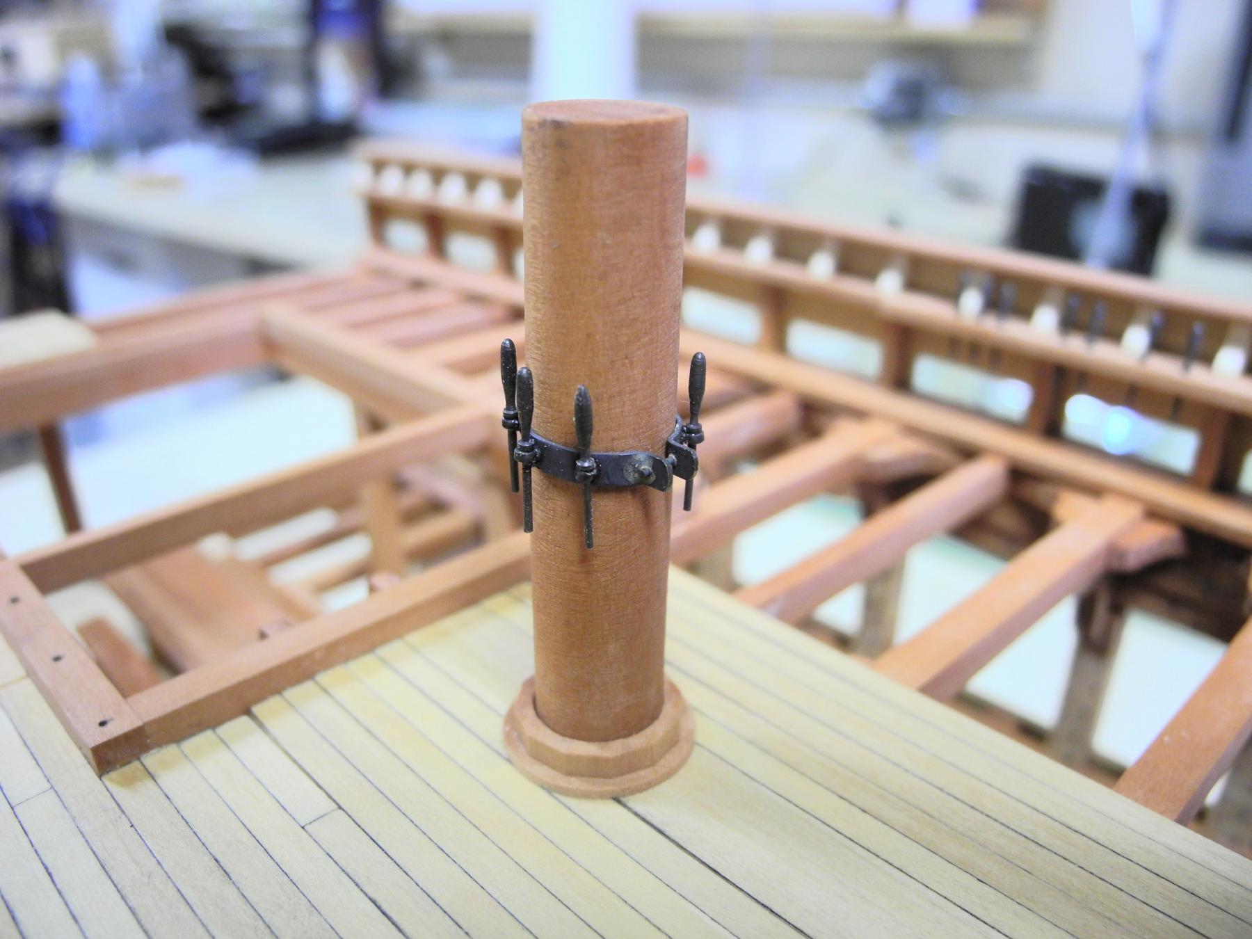
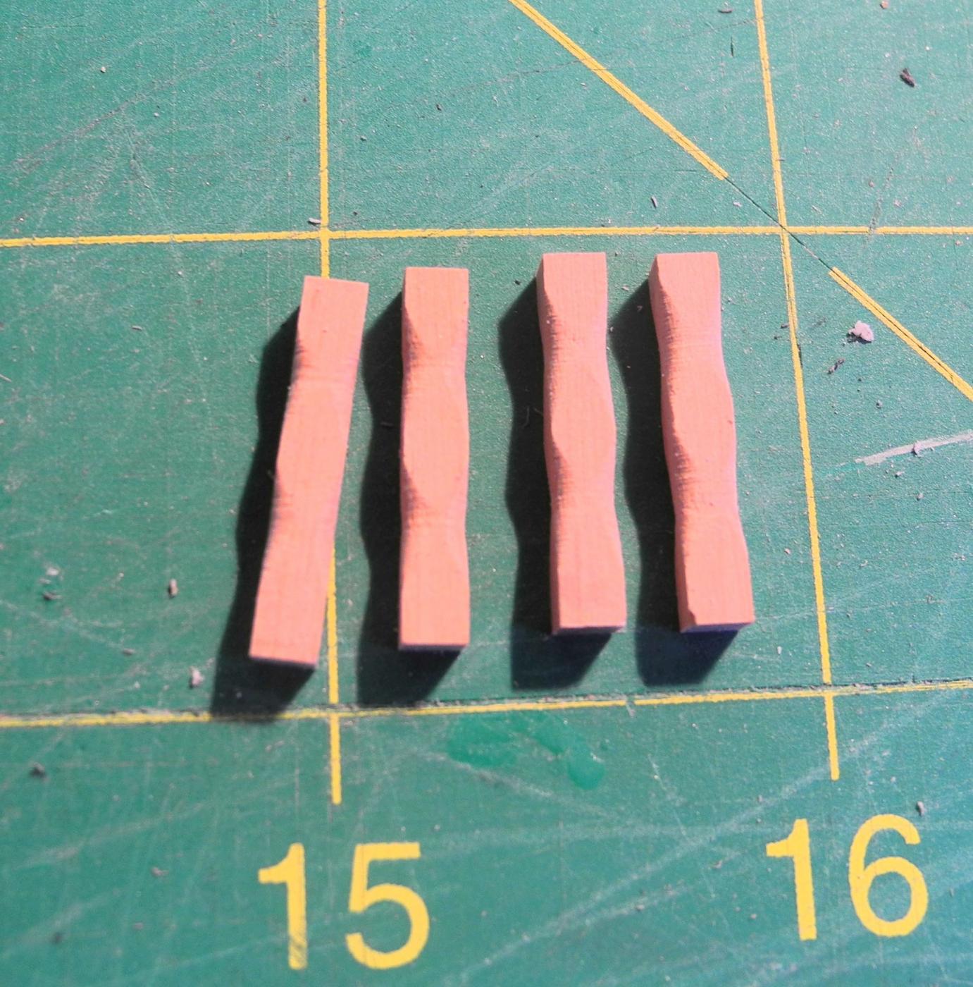
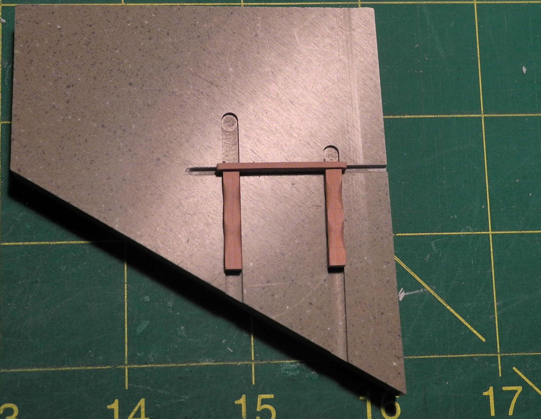
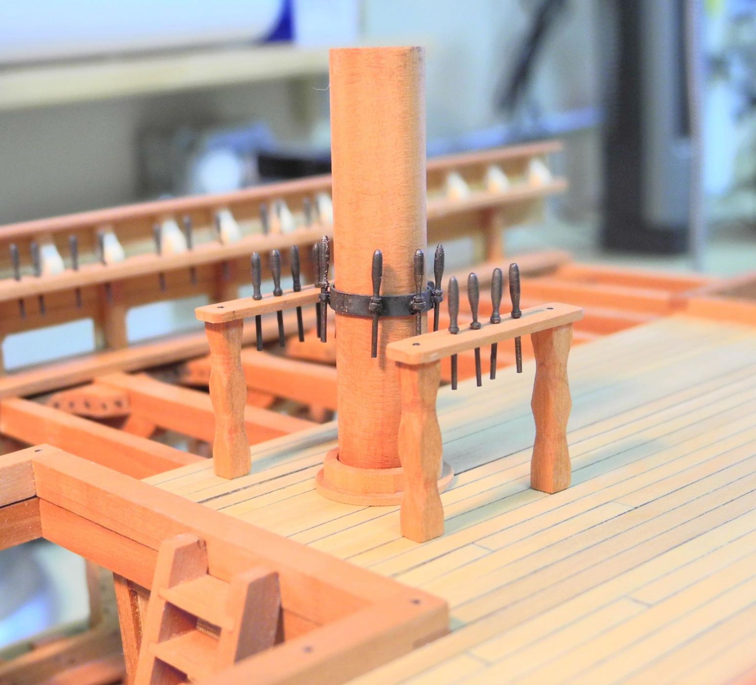
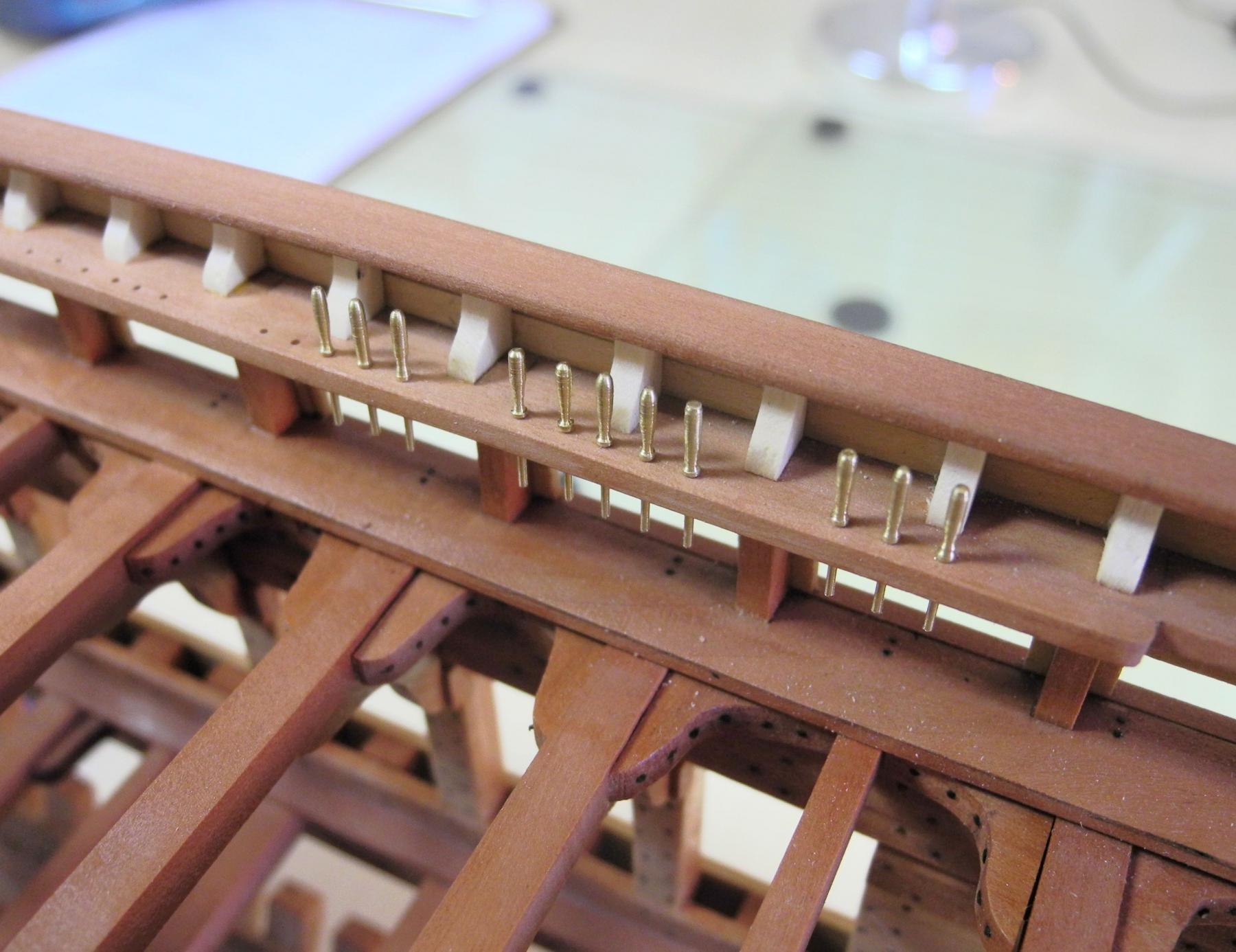
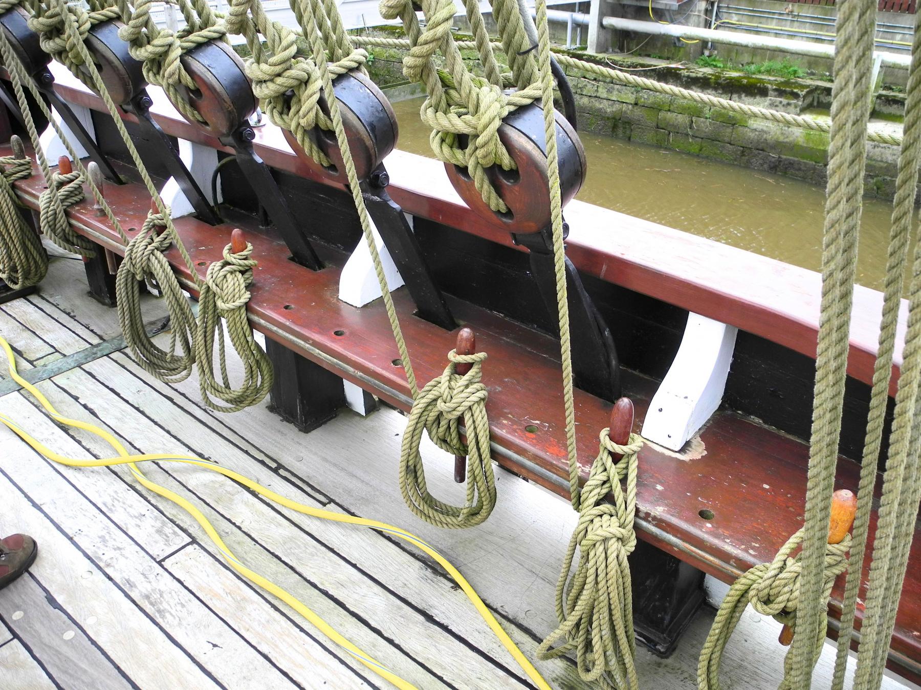
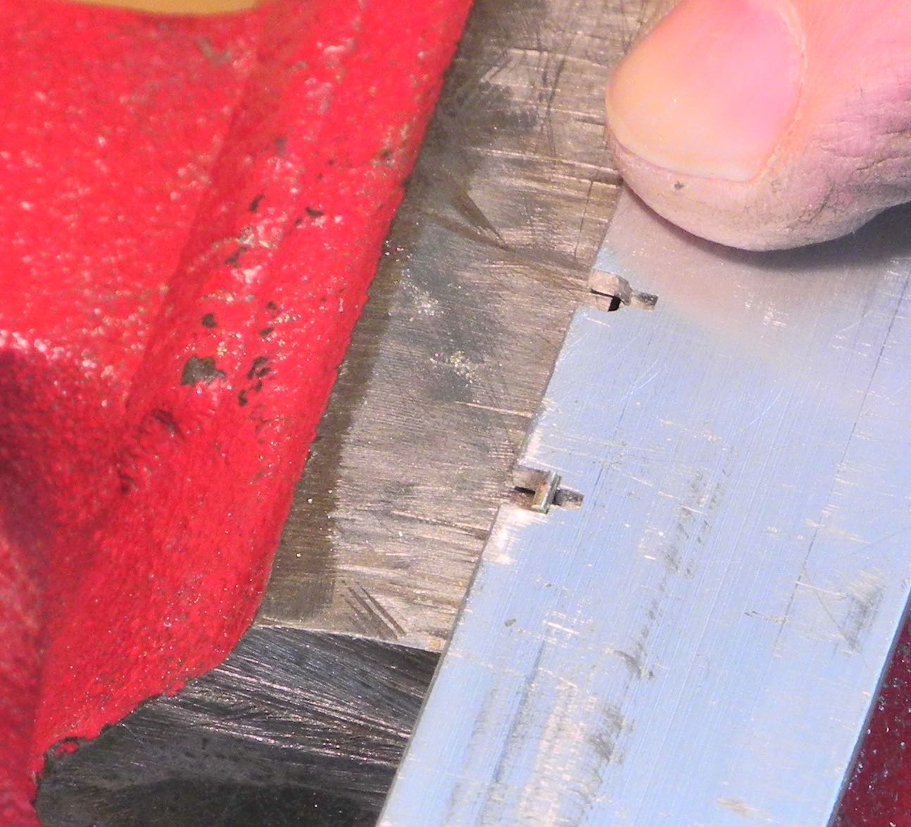
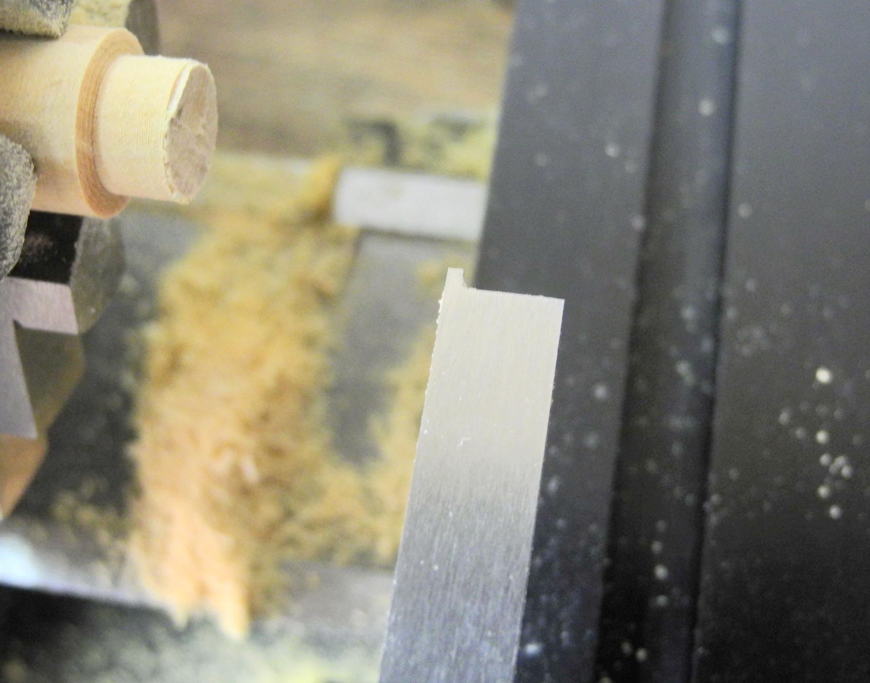
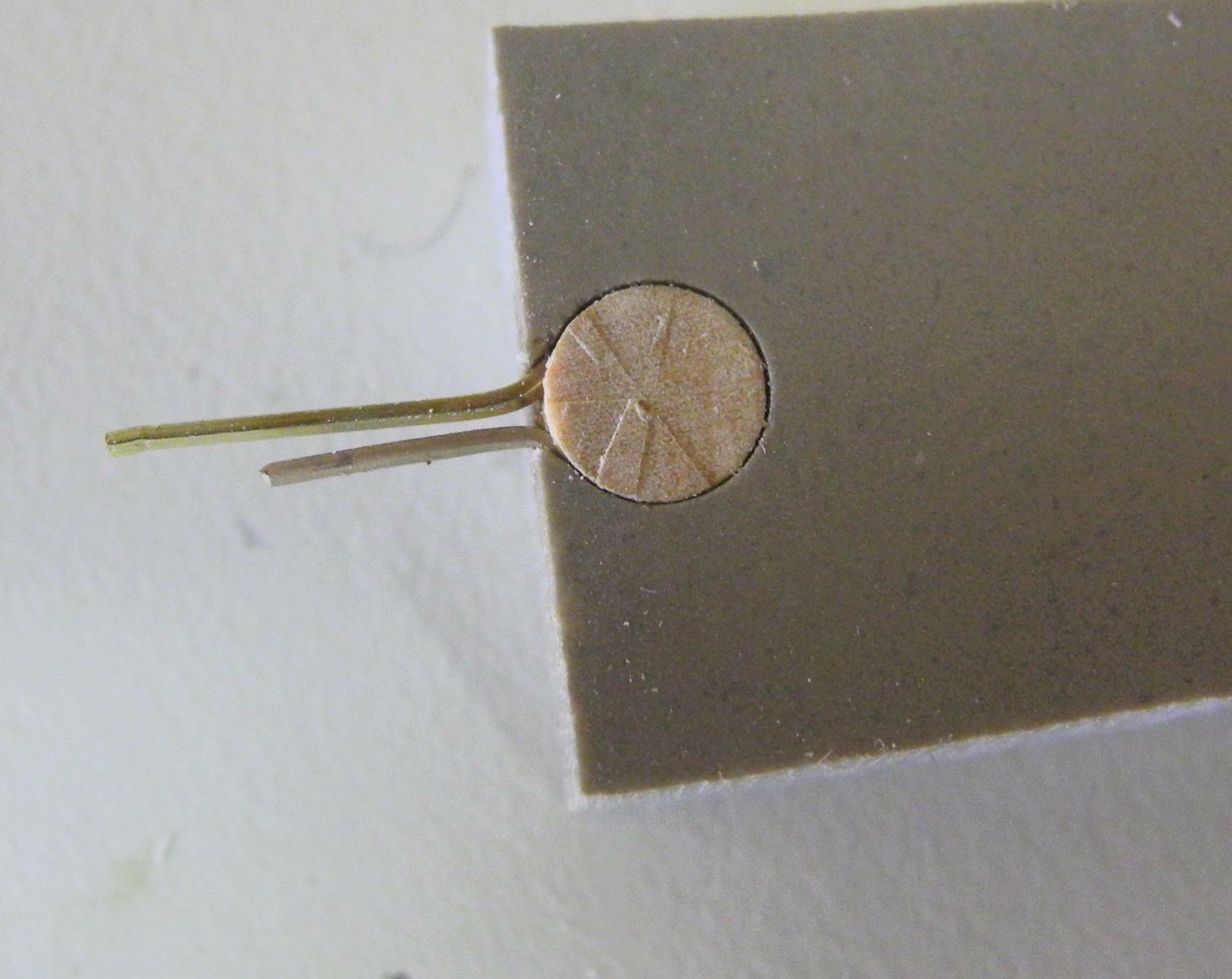
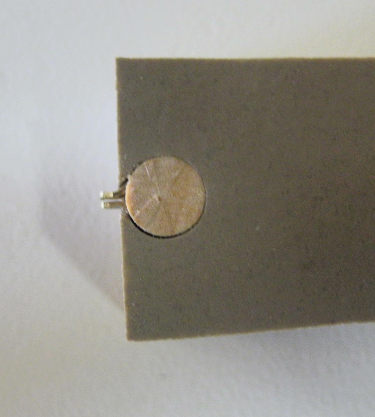
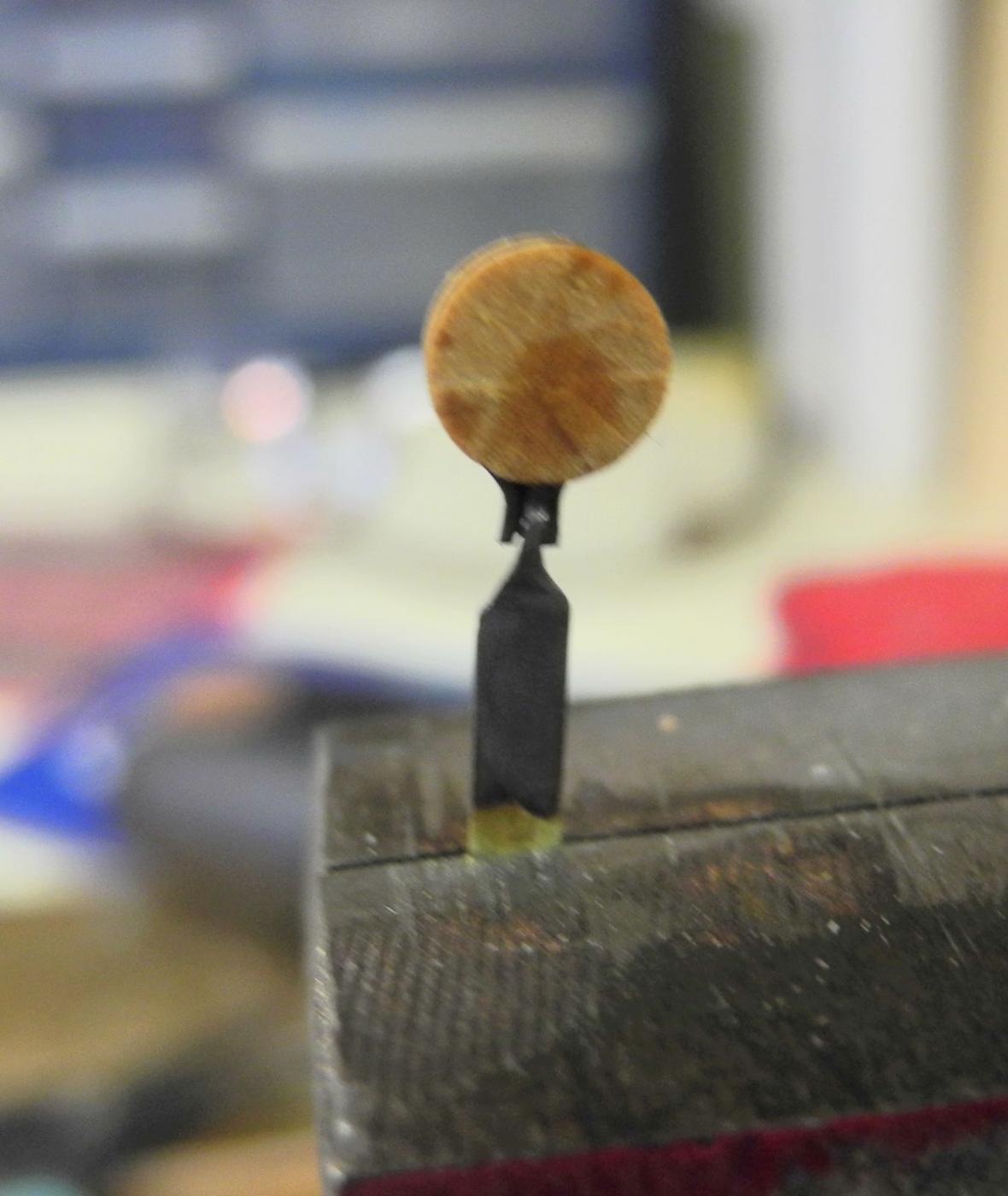
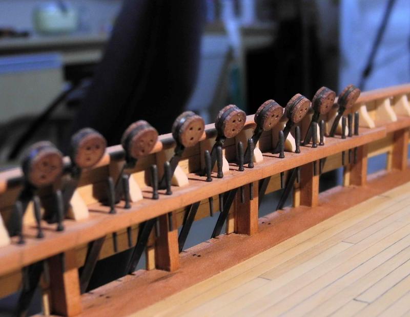
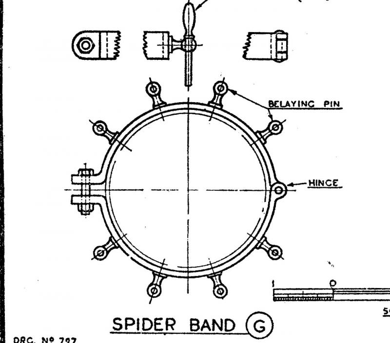
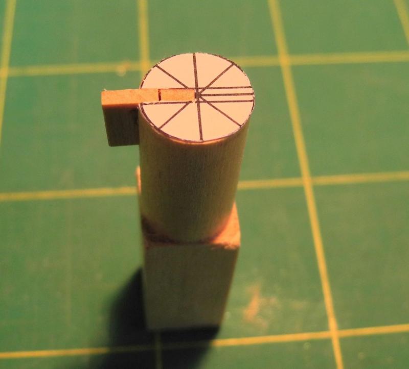
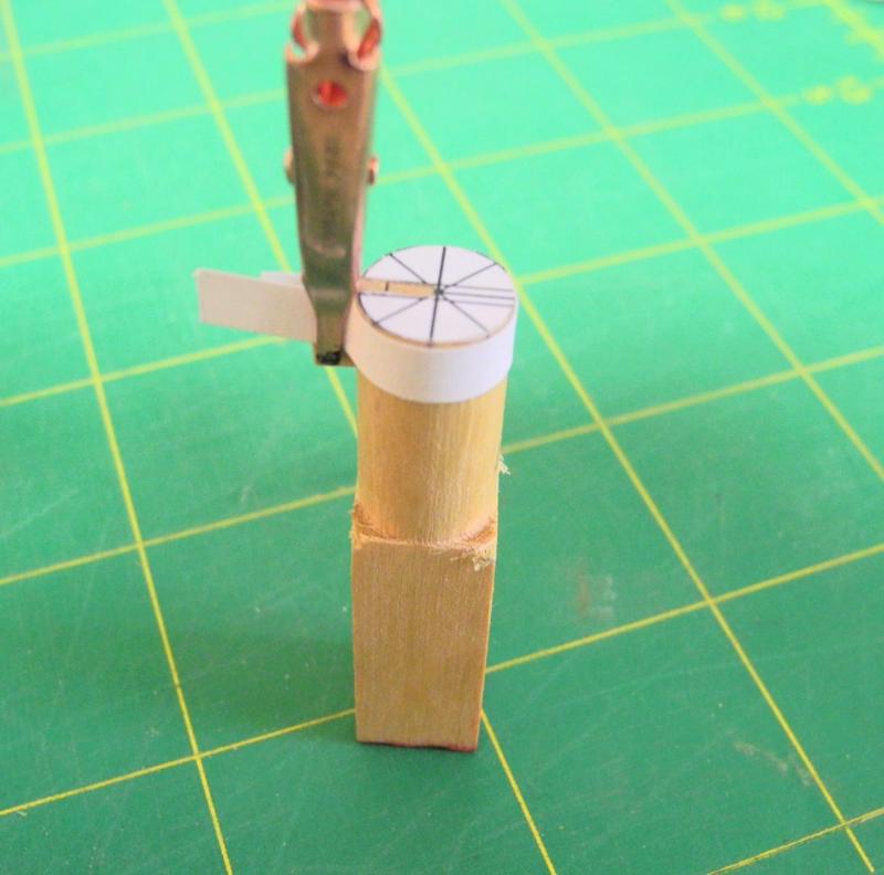
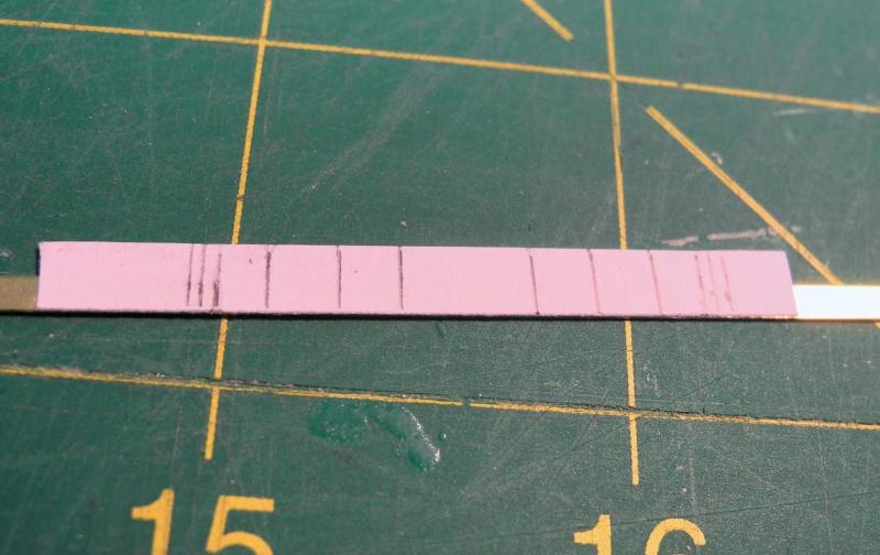
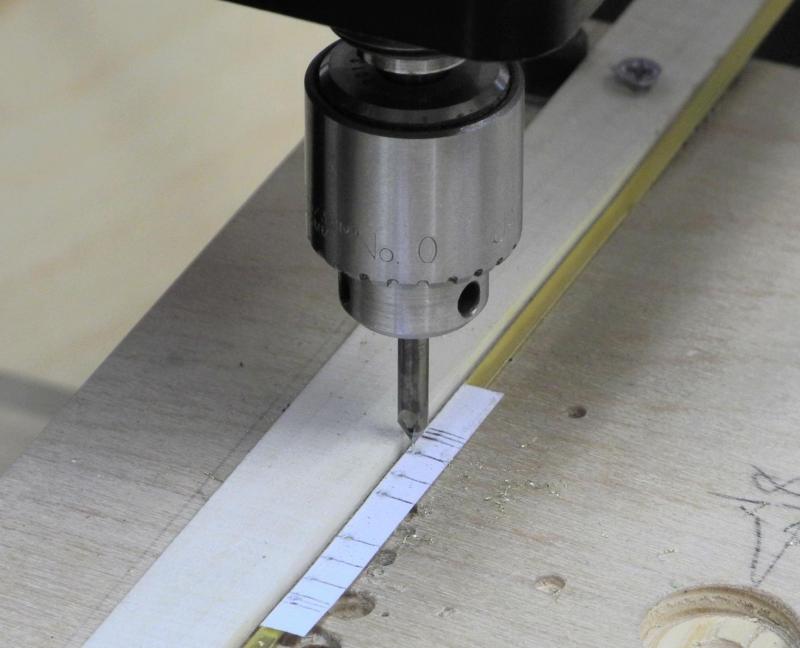
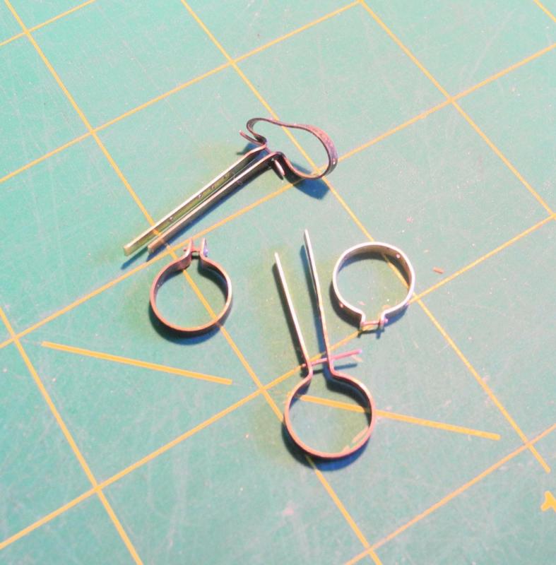
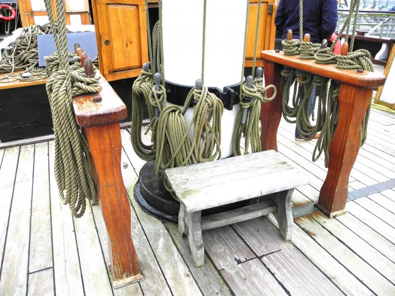
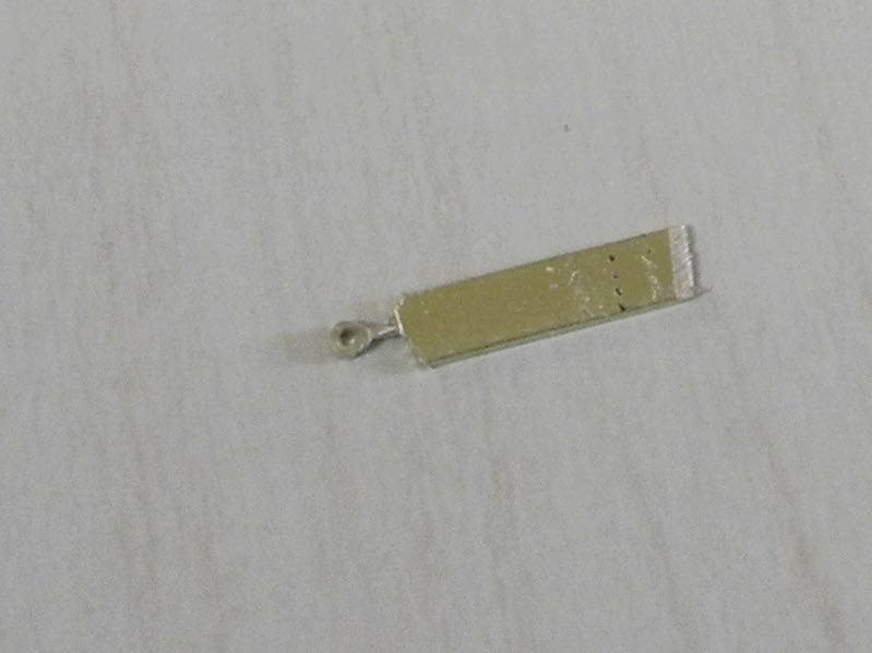
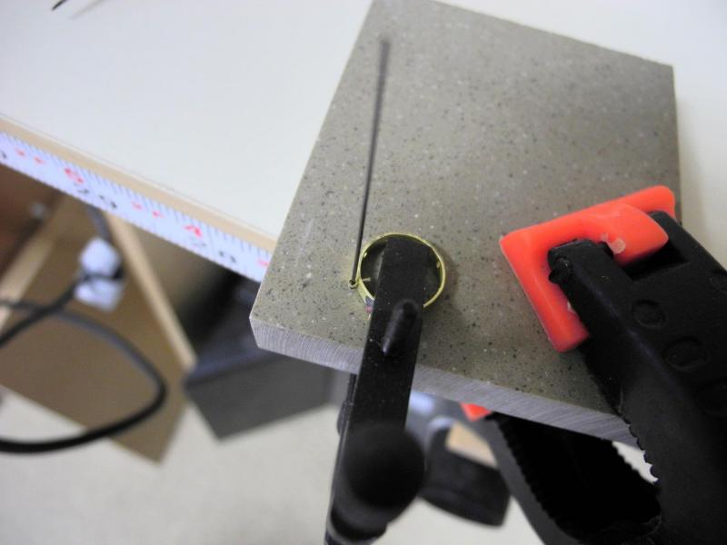
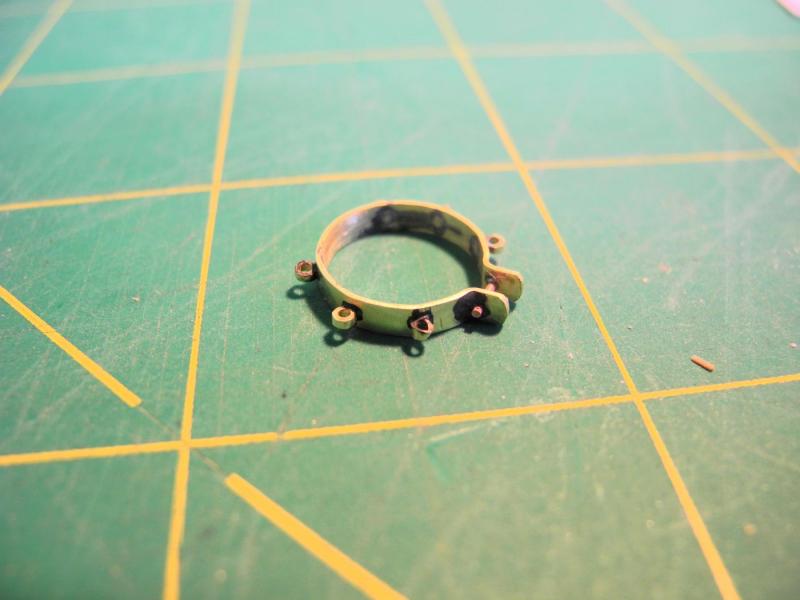
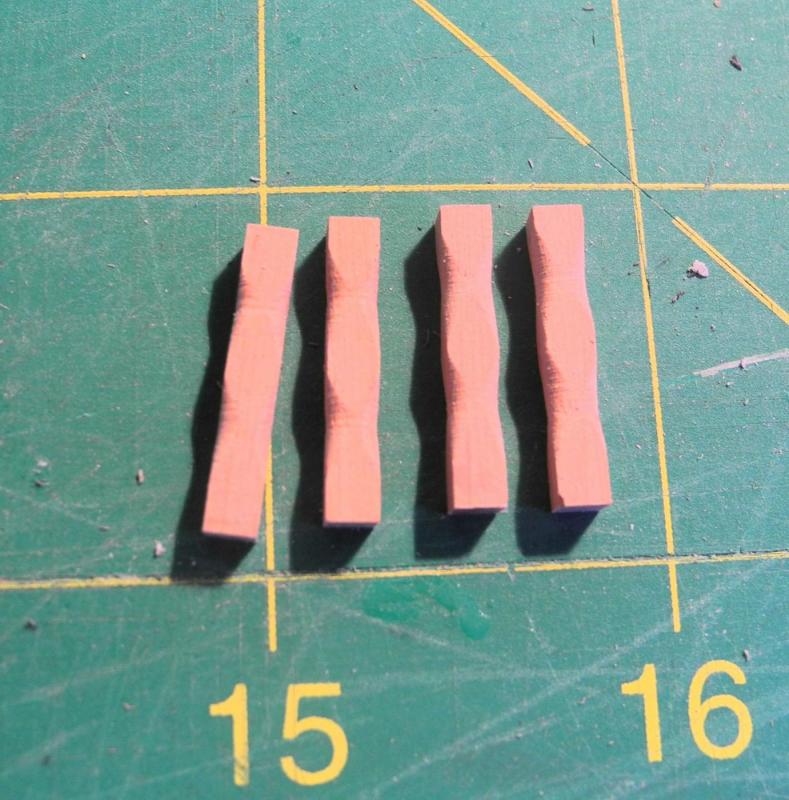
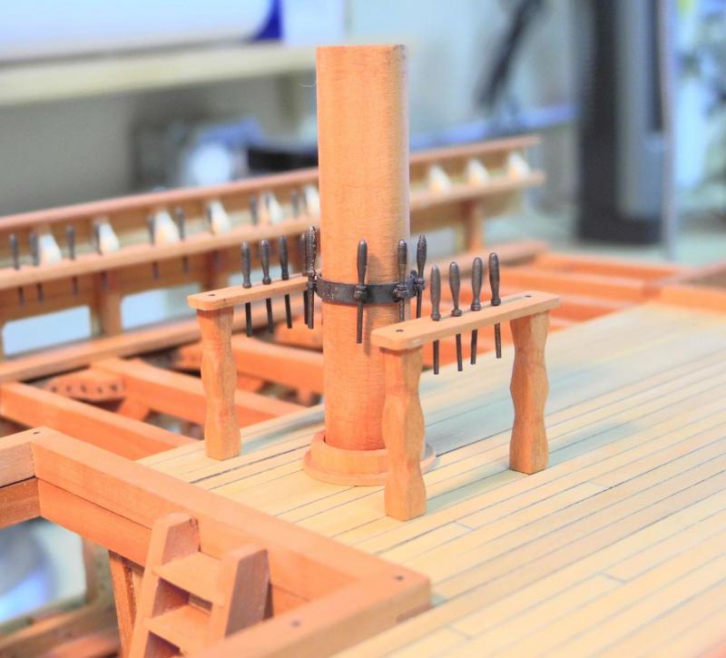
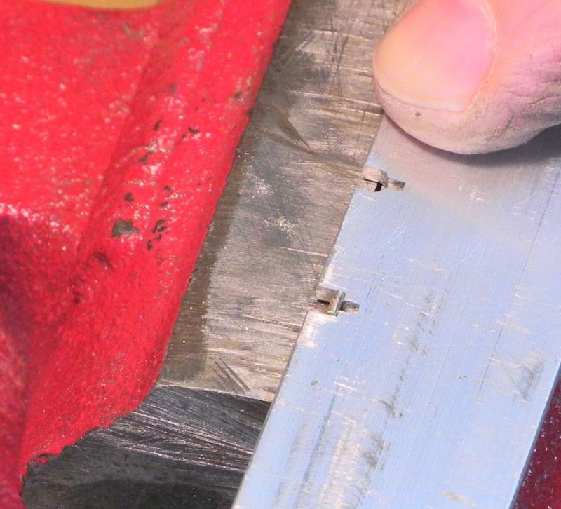
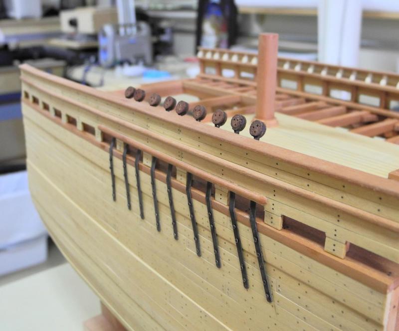
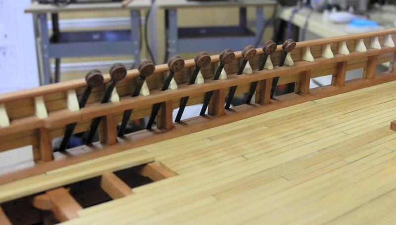
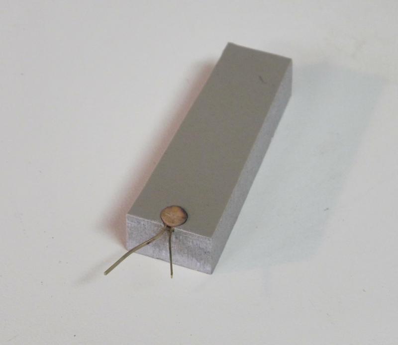
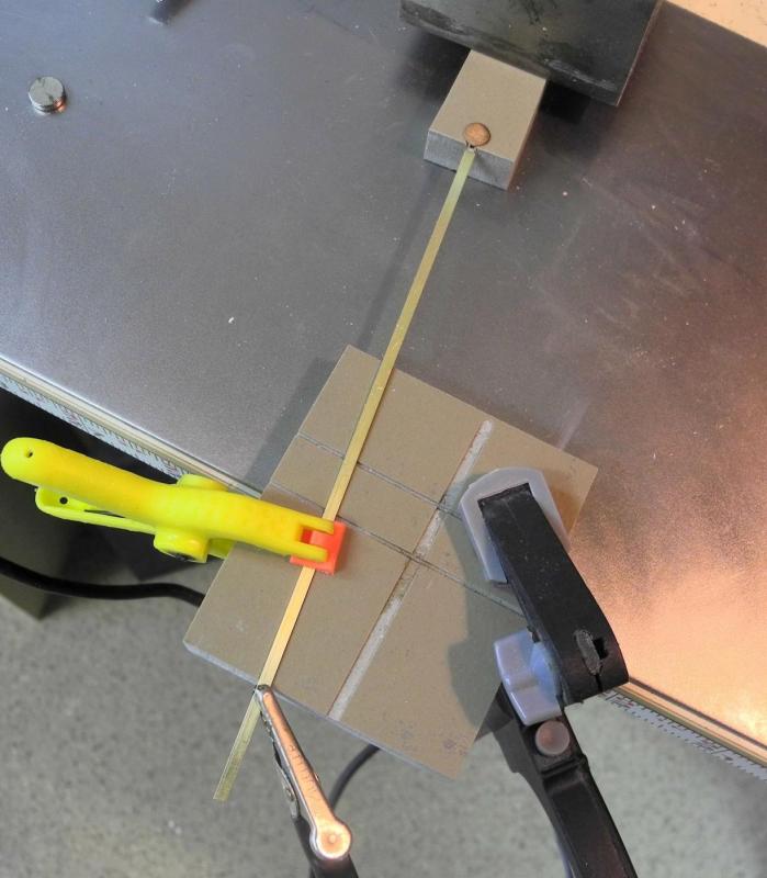
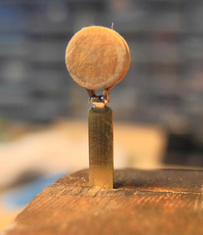
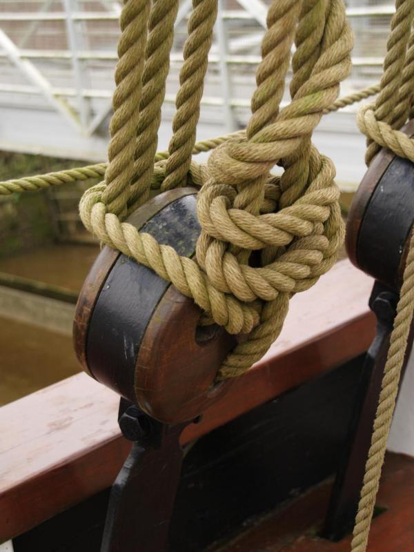
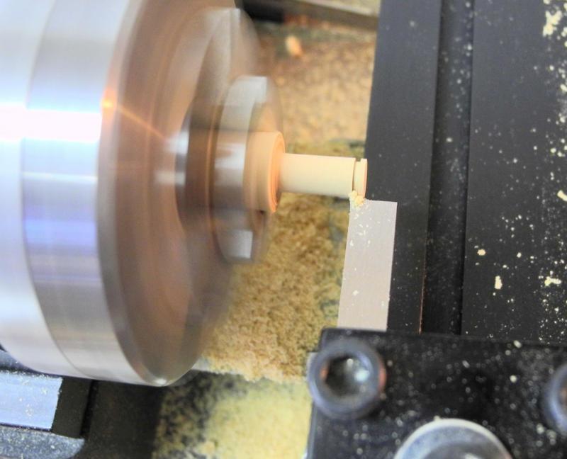
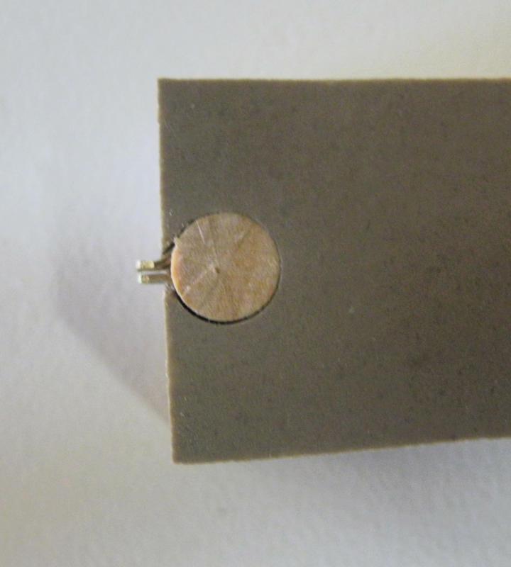
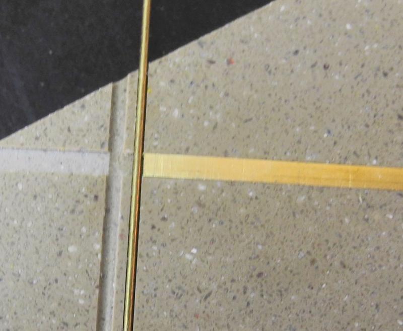
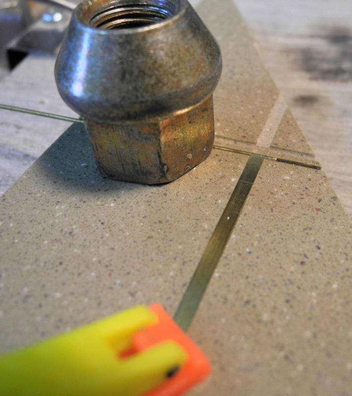
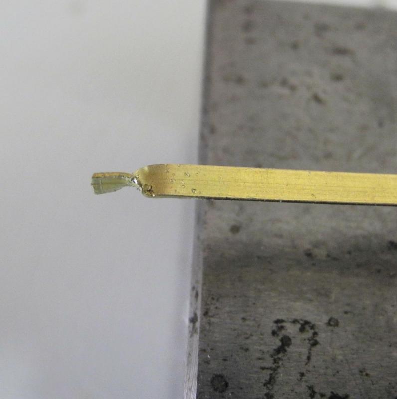
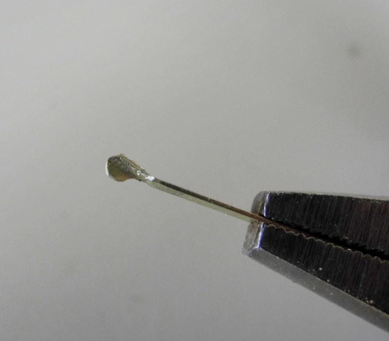
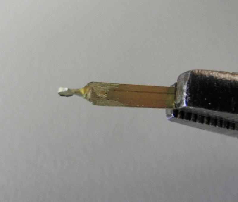
Part 52 – Pin Rails, Spider Band, and Fife Rails In the last post I questioned whether I should fully populate the pin rails or leave some positions open. I received several different comments and opinions, which I greatly appreciate. I decided to populate most of the pin positions, leaving several open. The following photos show the results: Dunbrody has Spider Bands on each of her masts - these are iron bands with sockets for some belaying pins, as shown in the following photo of the replica ship. Also note the simple fife rail configuration. I found the following drawing of a spider band in Harold Underhill’s book ‘Masting and Rigging’, and used it as the basis for making the spider band. The bands would be made by annealing a brass strip and bending it to form the band. The jig shown in the following photo was used to make the band. The jig was turned to the same size as the mast, and the protrusion is used to bend the projecting pieces of the band at the proper locations. A CAD drawing was made to identify the locations of the holes for the pin sockets and was pasted to the top of the jig. A strip of medium card stock was formed around the jig, and the hole locations were marked on the card stock. This strip was then glued to a brass strip and the holes were drilled. A centering drill was used to make the initial hole, and the final drilling to the correct size was done with a rotary tool. After several trial and error attempts An acceptable band was produced. There were several attempts to make pin sockets. I made some small rings from copper wire, but these didn’t hold the pins in a vertical position. I tried bending 1/64 x 1/32 strip around a drill of the appropriate size, but the socket holes were elliptical rather than round. I finally decided to form the pin sockets by shaping them with a rotary tool and diamond bits. 1/8 x .025 strip provided the correct depth. The strip was first drilled for the correct socket size, and the socket was then formed as shown in the following photo sequence: The outside diameter of the socket is .055, and the hole for the pin is .025 – the thickness of the pin socket is then .015, or slightly smaller than 3/4" in actual terms. The pegs for the sockets were shaped to .025. The sockets were then individually soldered onto the band using the following setup. The vertical piano wire was used to ensure that the sockets stayed horizontal during the soldering. The following photo shows the completed Spider Band before blackening. After blackening the Spider Band was installed on the mast and pins were added to the band. The final work involving the belaying pins was the manufacture and installation of the Fife Rails. As shown in the earlier photo, these are fairly simple affairs. The legs are not turned as spindles but are simply shaped. This was performed on the lathe with an appropriate sized file. A jig was used to ensure that the fife rails were square and that the legs were centered on the rails. Black monofilament was used to simulate the bolts that hold the rails and legs together, and belaying pins were added to the rails. This completes the work related to the belaying pins. So Dunbrody is now on the final stretch - the remaining work consists of creating the companionways, making and installing a bollard on the port side, and making and installing a capstan. Thanks everyone.


- 649 replies
-
- 25
-
-
- dunbrody
- famine ship
- (and 2 more)
-
Thanks Druxey - although when the work gets a little tedious I sometimes feel like the ship is my master! Hi Michael. I've been doing some more reading, and it looks like every pin location should have a specific purpose and therefore I would expect it to have a pin in it when under sail. Since my Dunbrody looks like it's in dry dock, I guess it really is my choice.
- 649 replies
-
- 9
-
-
- dunbrody
- famine ship
- (and 2 more)
-
Hi Chuck - great work. If you have a rotary tool you could try using a small ceramic stone for final shaping. They're available in white, green, and pink. The white stones are the finest. All of these stones can be shaped using a small diamond sharpening stick, so you could bring them to a very fine point for getting into tight areas. Most of these stones have 3/32 shafts, rather than the 1/8 found on Dremel, and can be found in a wood carving supply site. They're used extensively by bird carvers and other power carvers. I can send you more info if you want.
-
Thanks Carl. I used brass because I thought it gave me the best chance for success. I might give wood a try, though, based on your question. Thanks Ed. I've learned so much by reading your build logs and books.
- 649 replies
-
- 6
-
-
- dunbrody
- famine ship
- (and 2 more)
-
Thanks Druxey. Do you have an opinion on whether I need to put a pin in EVERY hole in the pin rails?
- 649 replies
-
- 4
-
-
- dunbrody
- famine ship
- (and 2 more)
-
Thanks Brian. That's what I'm seeing too, when I look at ship photos where you can see the pin rails. Also, when I look at the pins I've temporarily installed I'm thinking the pin rails will look overcrowded if every hole has a pin in it. So I'm leaning towards having some random empty holes in the pin rails. Waiting for more comments, though.
- 649 replies
-
- 4
-
-
- dunbrody
- famine ship
- (and 2 more)
-
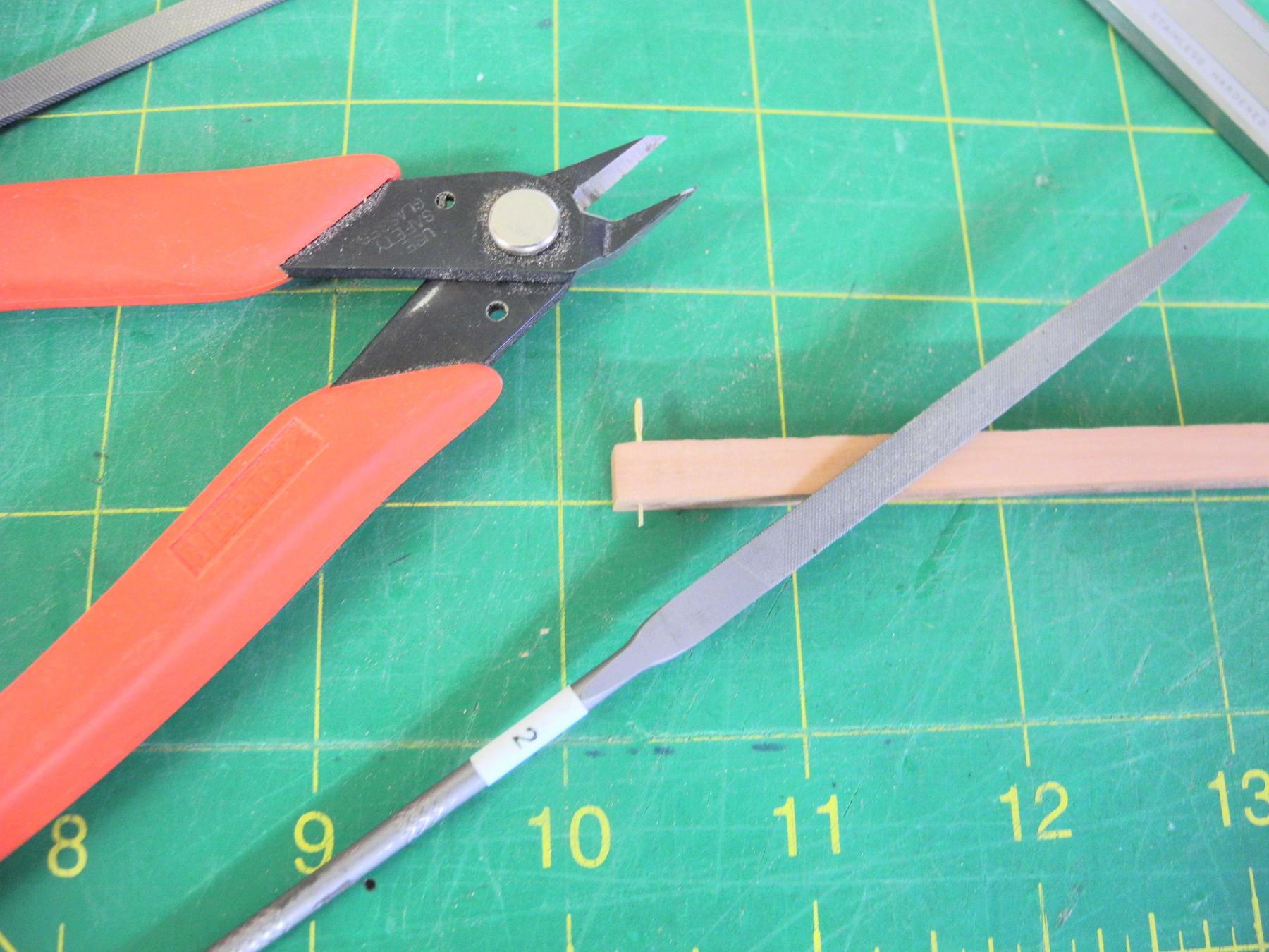
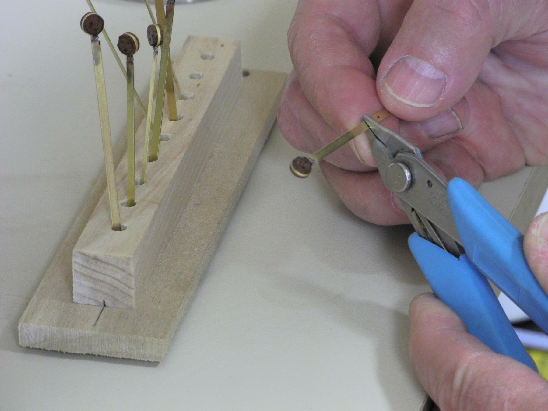
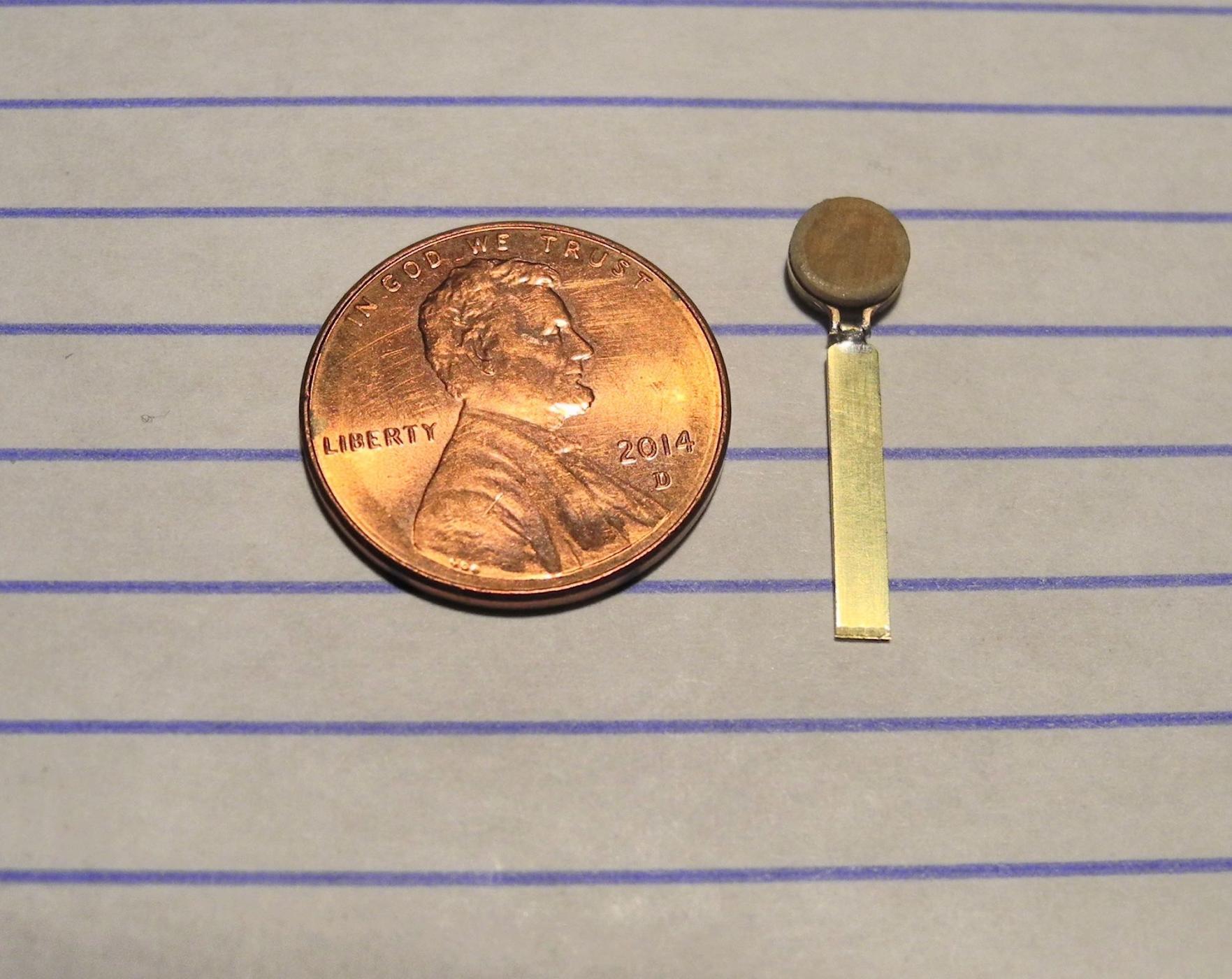
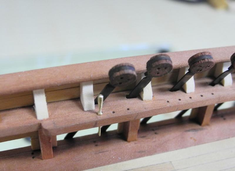
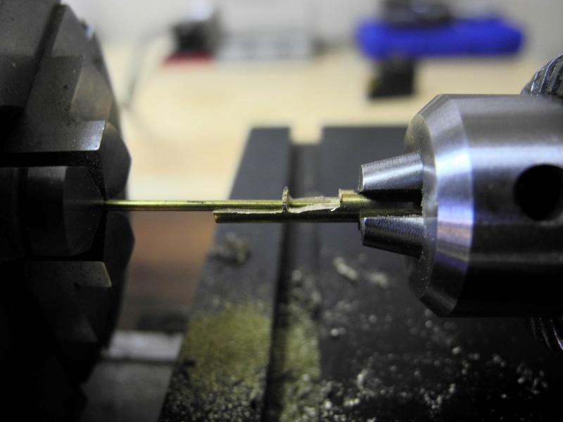
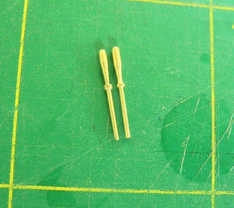
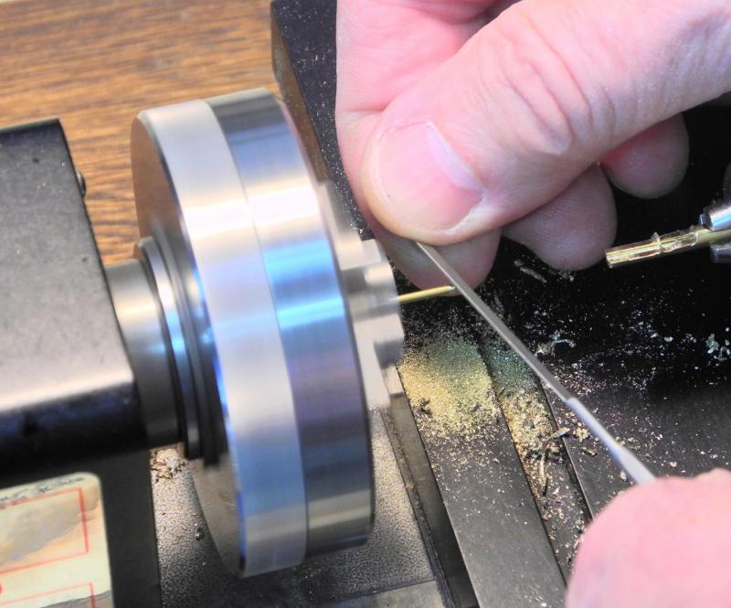
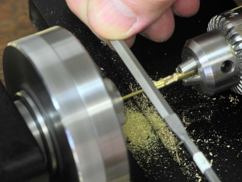
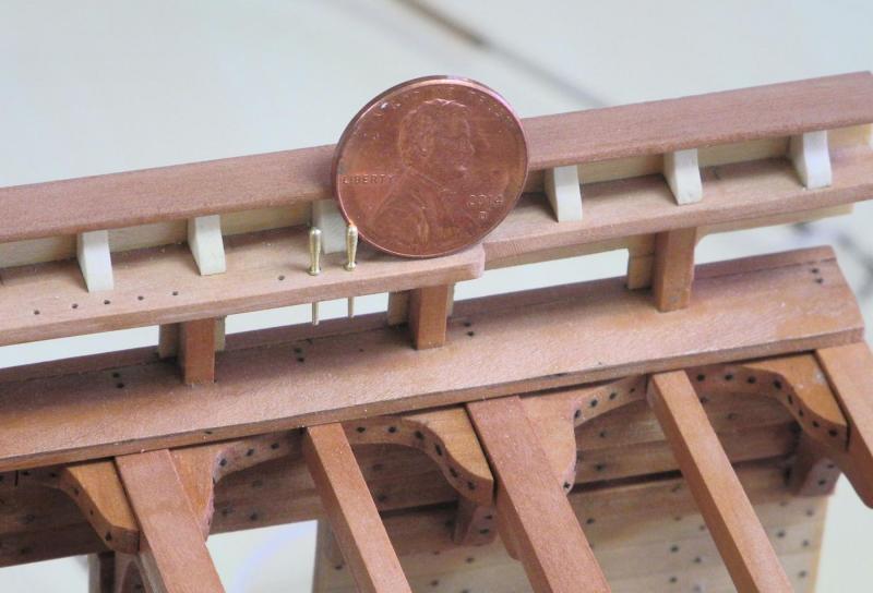
Part 51 – Belaying Pins Even though there will be no actual rigging on the Dunbrody sectional model, I think it’s still appropriate to have belaying pins in the model. I like EdT’s method of making belaying pins, as I think it gives me the best chance to make reasonable-looking pins. I followed Ed’s lead, and first drew a belaying pin in CAD – I decided on an 18-inch overall pin length, with a 12-inch shaft. After converting the full-size measurements to 1:48 scale, detailed measurements were used to make the pin-making fixture on the milling machine as described in Ed’s Young America post. The stock used for the belaying pins is 3/64 round bar. My very first attempt at using the fixture was pretty successful. The following photo shows the first pin – the prototype. The following photo shows the pin-making fixture, based on Ed’s design. After making a couple more prototypes it became apparent that some changes needed to be made to achieve a consistent size. The hole that had been bored for the bar was too long, so the handle length varied noticeably from pin to pin. The shafts of the pins were also noticeably different lengths. To correct the first issue, the hole was blocked off so that the length of the handle was fixed. The second issue was addressed by making a ‘measuring fixture’ for the shaft – really just a piece of wood of the correct thickness with a hole drilled through it. The new pin is inserted in the hole, the excess shaft length is clipped off, and the remaining shaft length is trimmed to the proper length by filing. The following photo shows the first two pins made with these corrections. In the photo enlargement it’s apparent that the collar of the pin is a different size between the pins. This resulted from misalignment of the pin after removing the fixture for measurement of the pin and then resetting the fixture (the pin wasn’t inserted into the fixture completely). The variance isn’t apparent in regular viewing, but it’s something that’s easy to watch for and prevent. The manufacturing process starts by filing the end of the handle to a nice round shape. All steps use different grades of files, starting with coarse (either a grade 0 or 2) then progressing to fine (grade 4) and finishing with an extra fine file (grade 6). The pin is then inserted in the fixture and the flat is filed down to the correct thickness. A caliper is periodically used to measure the thickness until the correct .025” thick shaft is created. This step takes the most time and uses the coarsest files at the beginning of the step. The following photo shows the first pins inserted in the pin rail, along with a penny to illustrate the size of the pins. The first day’s production of belaying pins totaled 11 pins. With more experience I think I’ll be increasing production, but there are still a lot of pins to be produced. This leads to a question I have: should all of the pin holes in the pin rails be populated with pins? There will be 8 pins across the two fife rails, and another 8 will be in the Spider Band. Each pin rail on the model has holes for 22 pins (this is from the construction plan, but seems excessive to me), so populating all of the pin holes would result in 60 belaying pins (assuming belaying pins in the unfinished starboard side). The photos taken on the replica ship show a lot of open holes in the pin rails. I’d appreciate comments and suggestions on this question – but I’ll continue to make the belaying pins for the next few days (maybe longer). Since this work is very repetitive I’ll probably occasionally interrupt it to work on some other remaining tasks in order to break the monotony. Thanks everyone!


- 649 replies
-
- 22
-
-
- dunbrody
- famine ship
- (and 2 more)
-
It looks great, Bob. Looking forward to seeing it (and you) next week.
- 348 replies
-
- 5
-
-
- pequot
- cable ship
- (and 1 more)
-
Thanks Bob. I'll definitely bring it. Thanks, Tom. Took a lot of trial and error, but that's always worthwhile.
- 649 replies
-
- 4
-
-
- dunbrody
- famine ship
- (and 2 more)
-
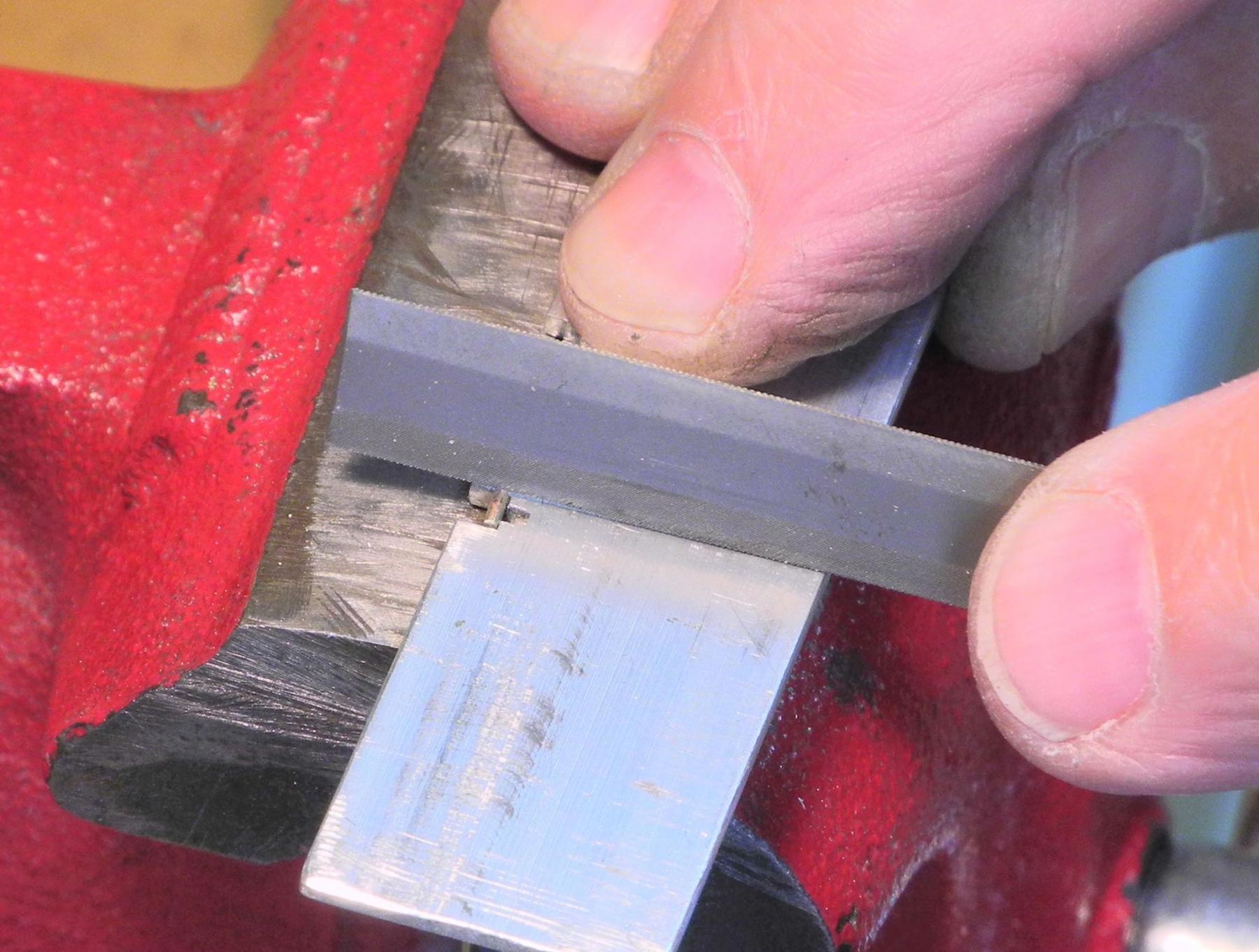
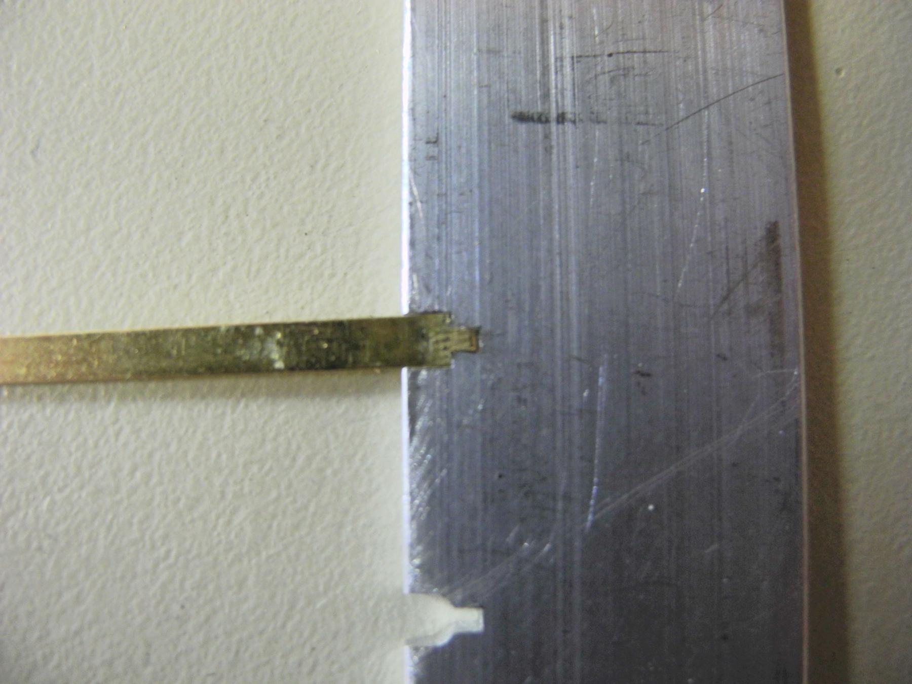
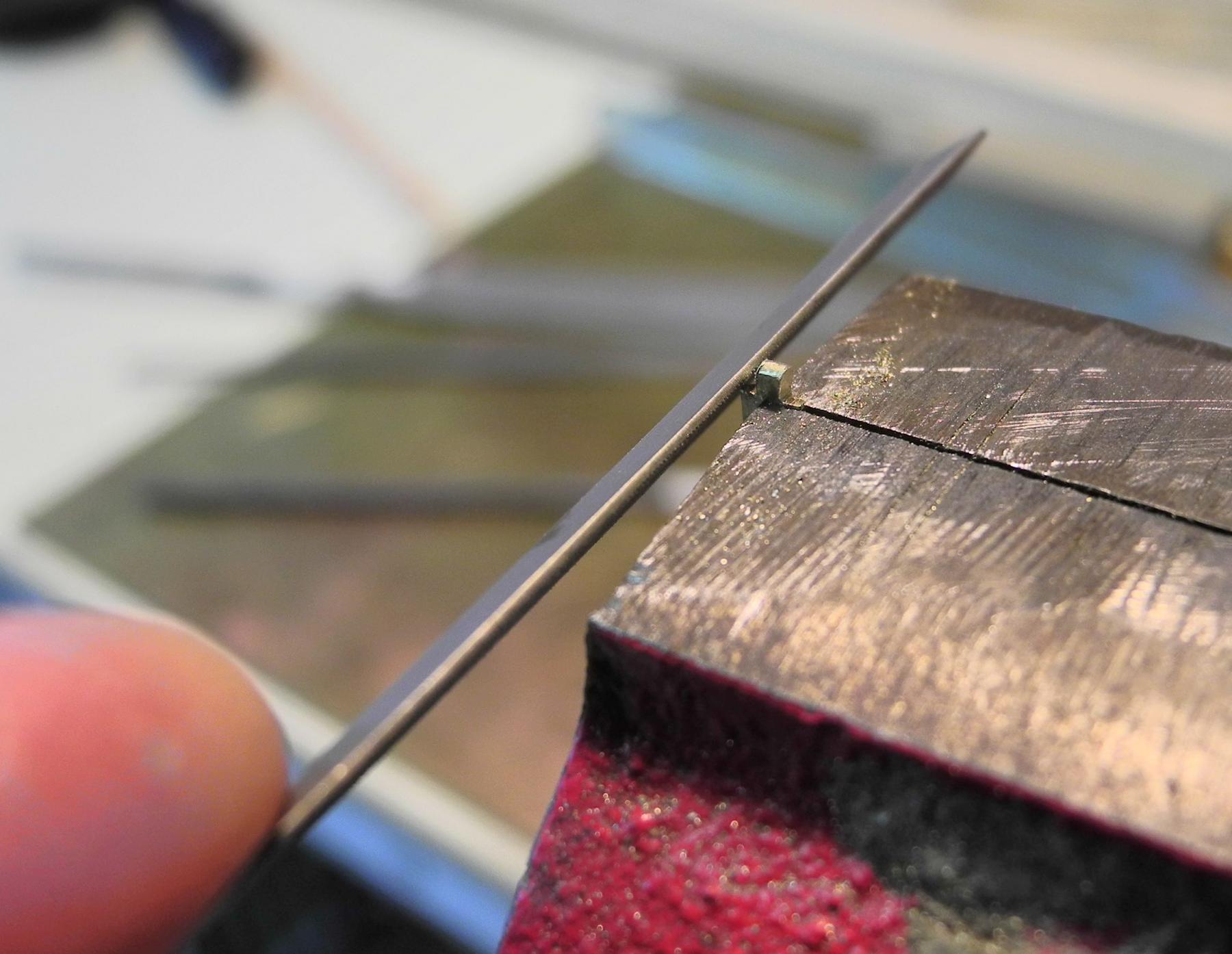
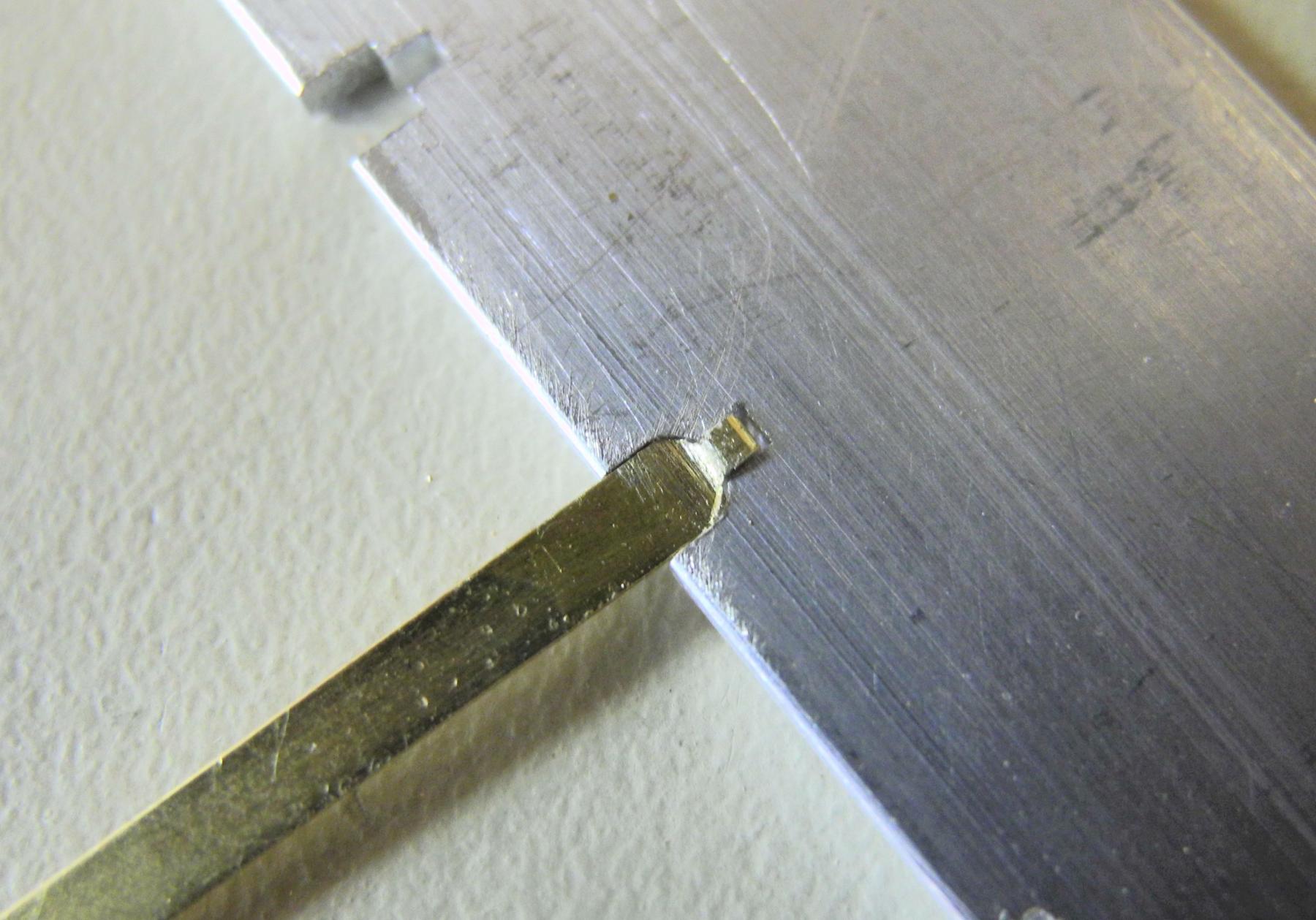
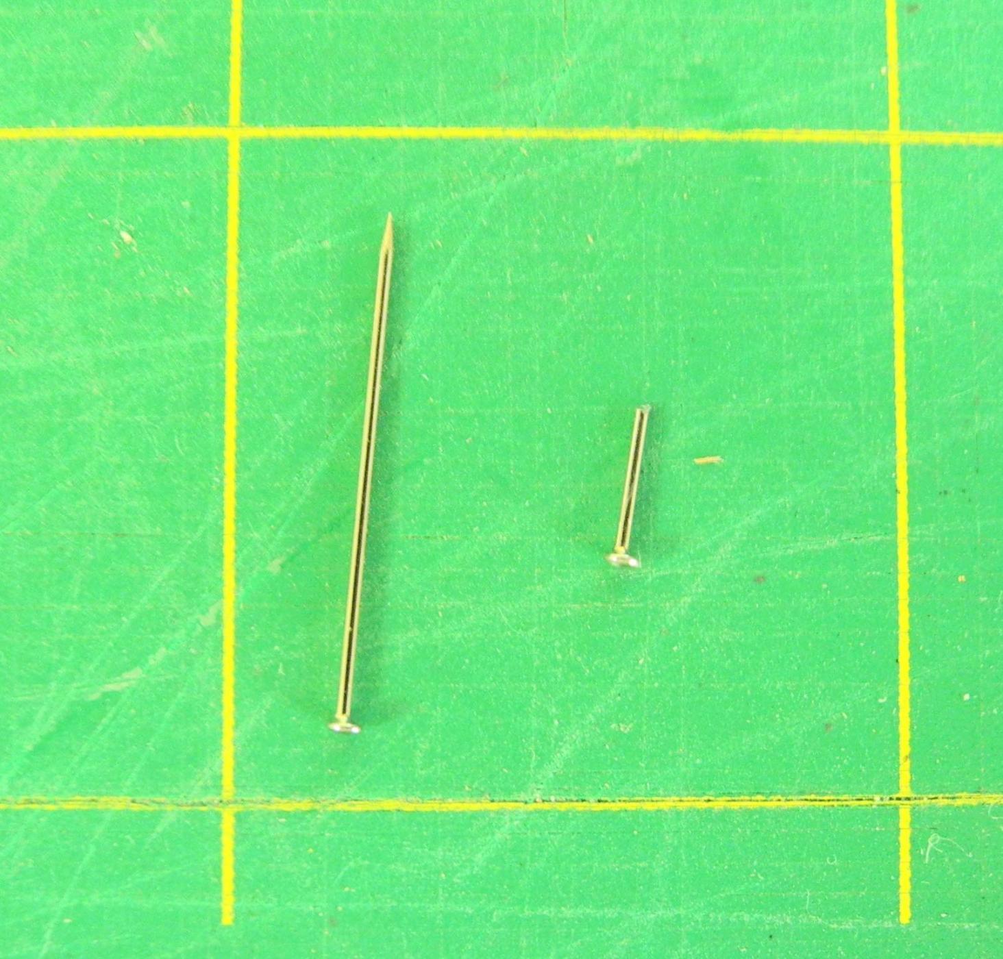
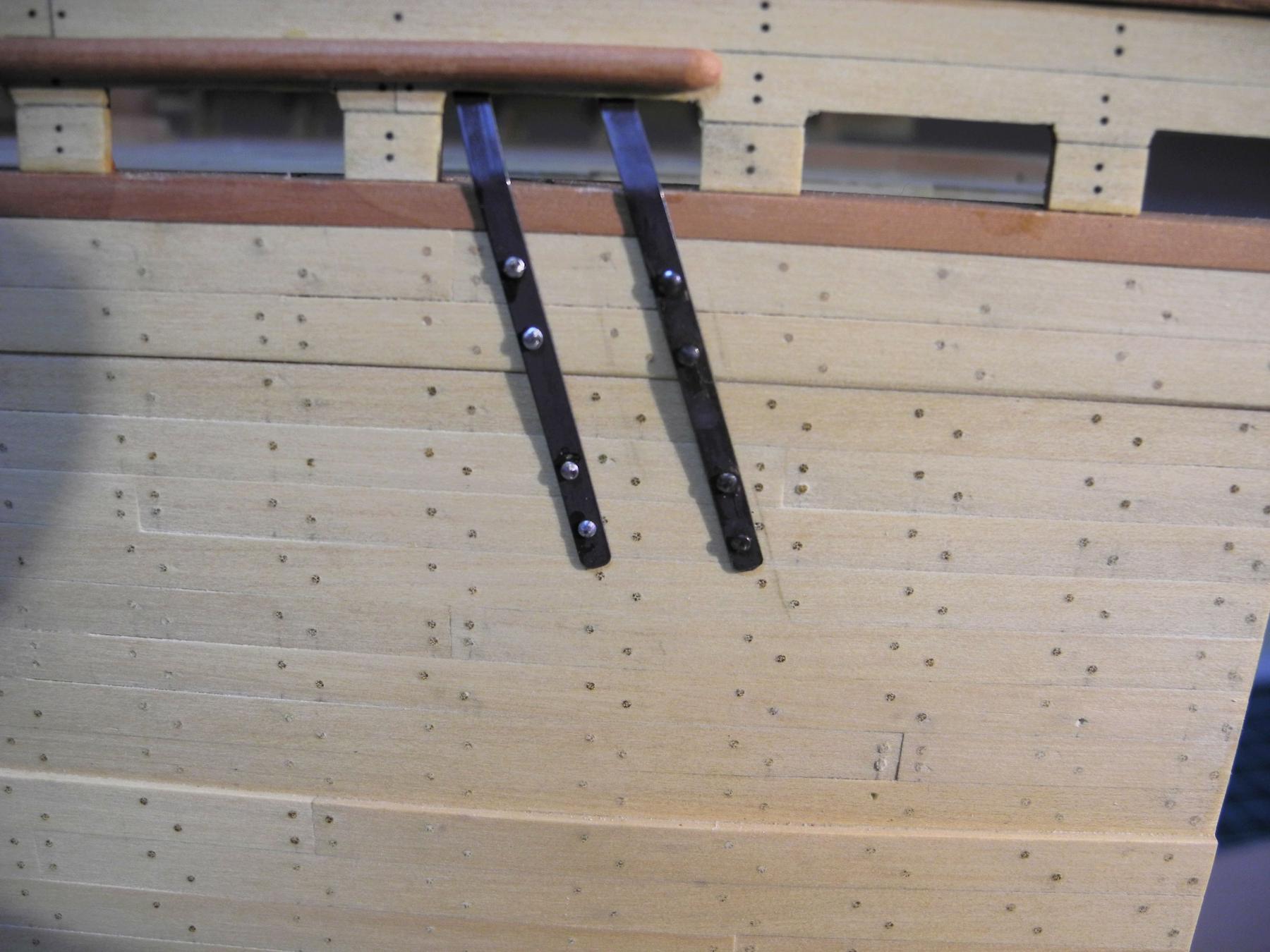
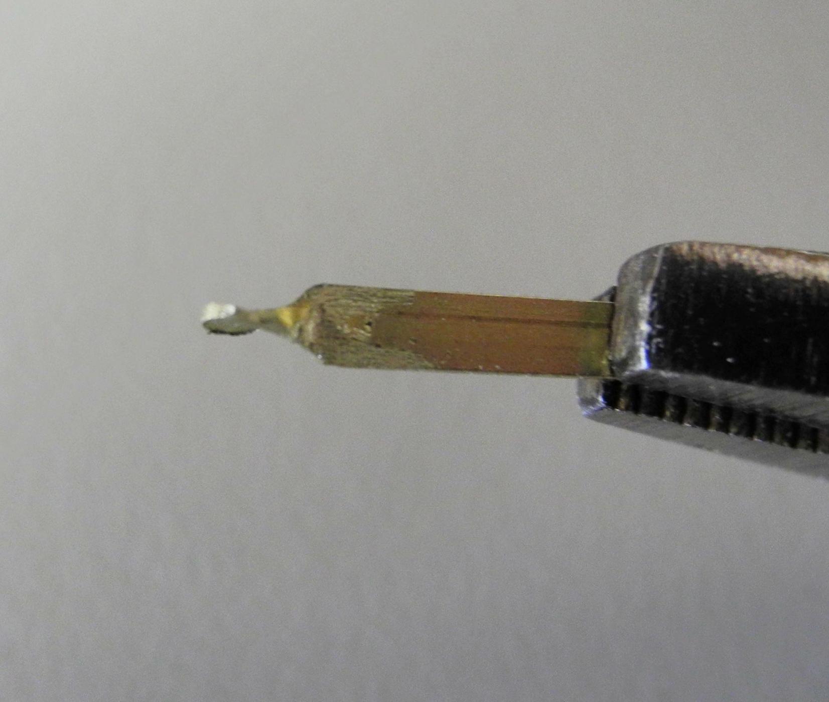
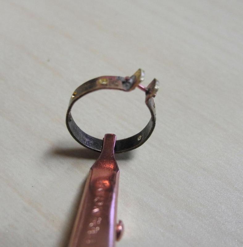
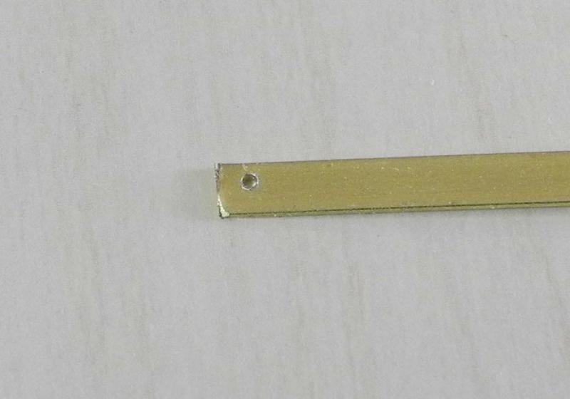
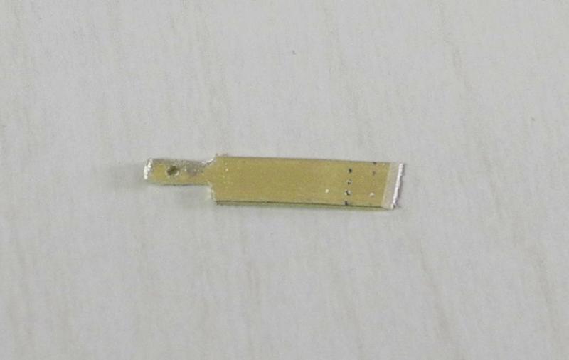
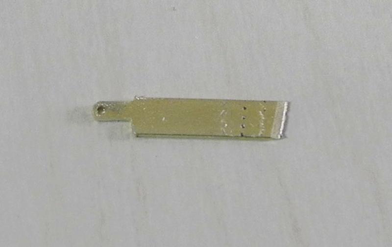
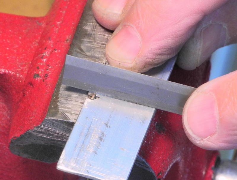
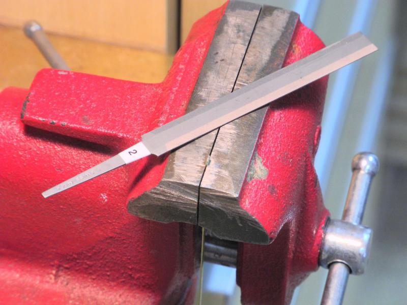
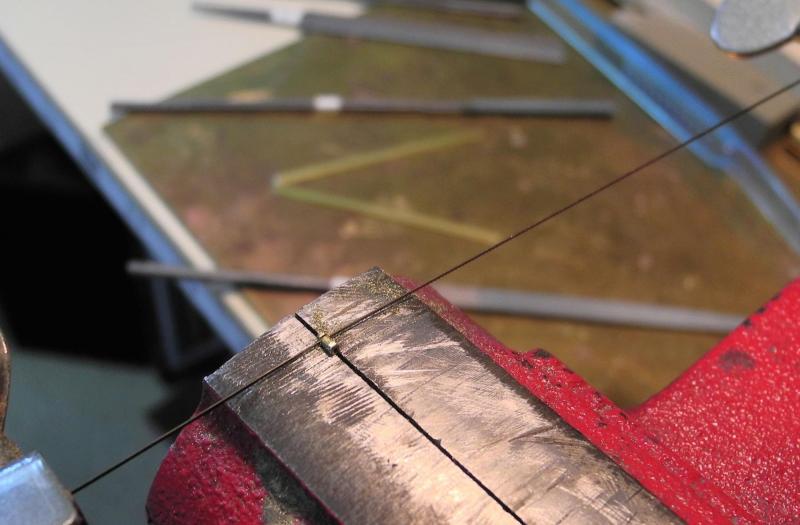
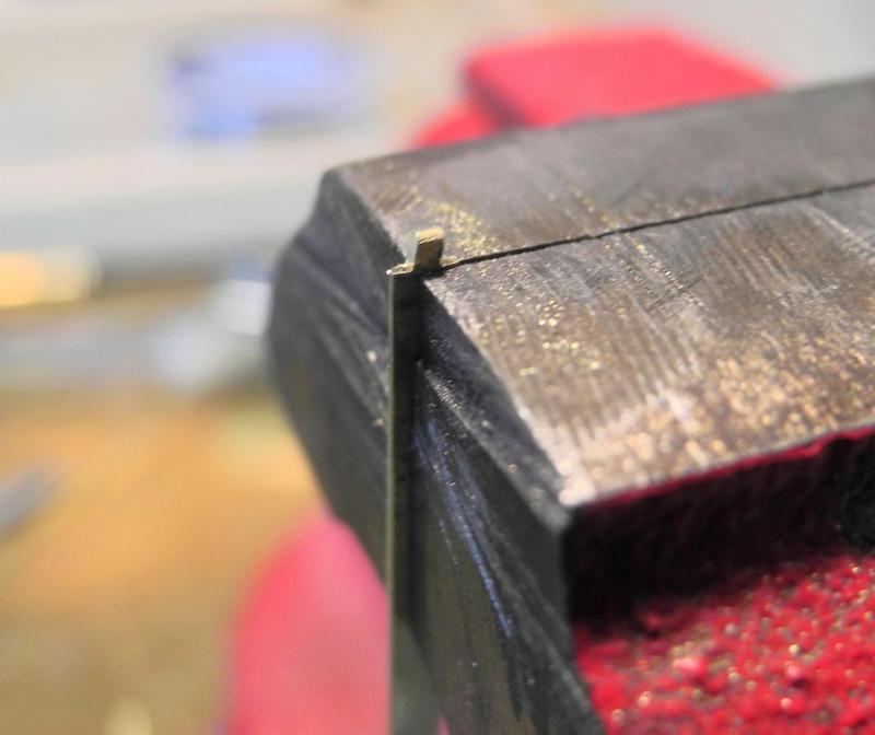
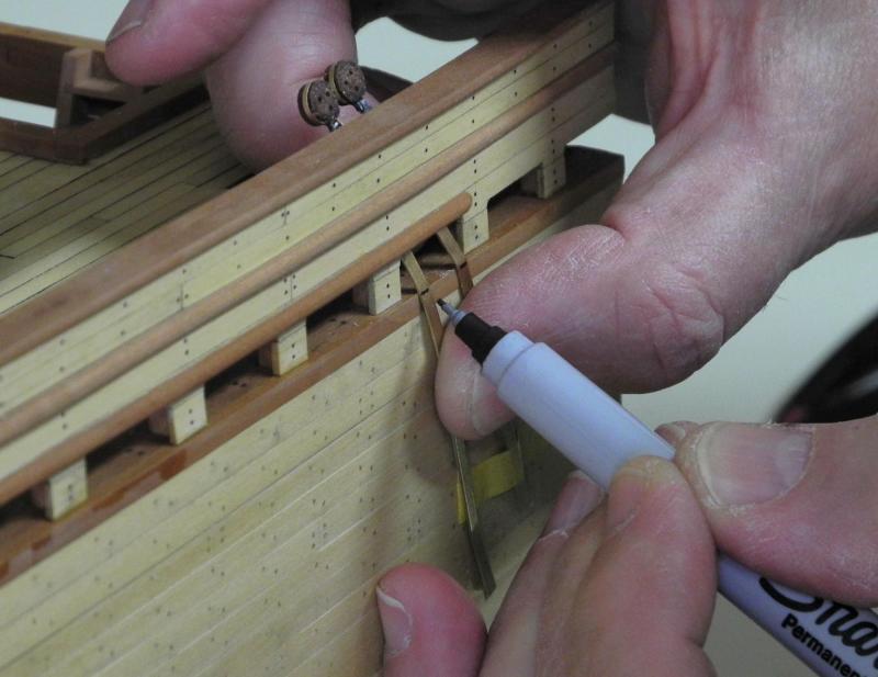
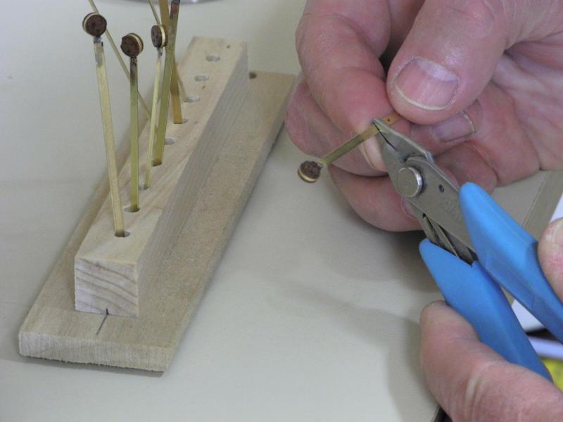
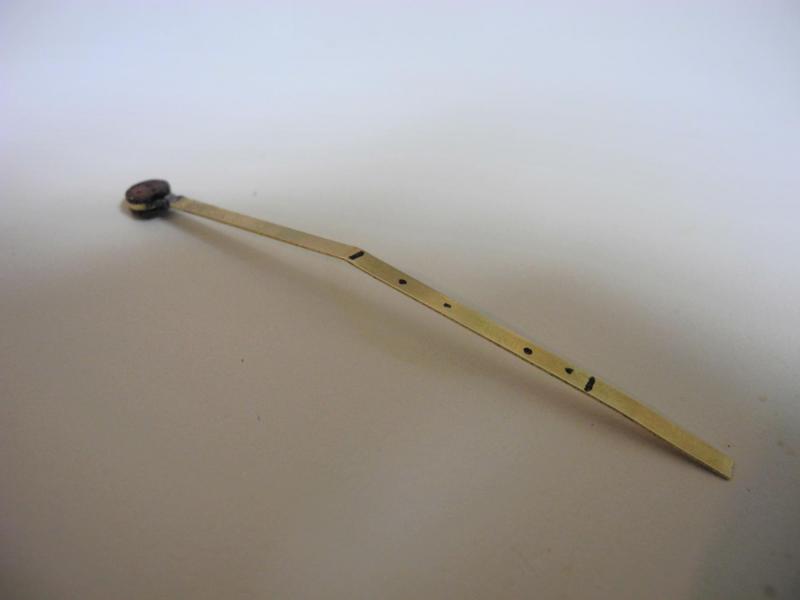
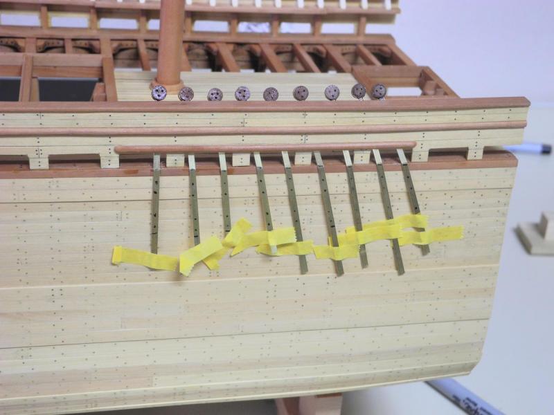
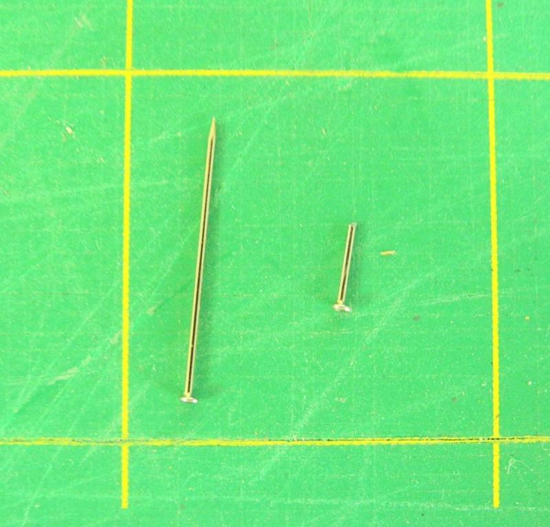
Part 50 – Deadeyes and Chainplates Version 3 Making the deadeyes and chainplates became more of a trial than I expected. It became clear that soldering a small round bar to the top of the chainplate wasn’t a good solution, since the heat for soldering the stropping band to the chainplate was too close to the previously soldered joint, and often caused the joint to fail. So another approach was needed. The new solution called for only one soldering process. The simulated bolt at the top of the chainplate was created by annealing the end of the chainplate, folding the end over on itself, and then filing it to shape. In this way there is still only a single piece of stock, with no soldered connections to come loose in subsequent soldering. Once the simulated bolt was ready, it was placed in the vise and the shaping template was placed over it. The boundaries of the ‘bolt’ were then marked with a screw slotting file. These files (shown in the next photo) have cutting surfaces on the edges only, and can be used to cut a fine line. The boundary lines were used as guides for a jewelers saw, used to remove the waste. After the initial shaping via the saw, the shaping of the end of the chainplate was finished with a fine file – using the template as a frequent check for fit. The shoulders of the chainplate still needed to be shaped. The chainplate was held in the side of the vice, with the shoulder exposed. The shoulders were shaped with a fine file, and were frequently checked against the template. Once shaping was completed, the chainplate was ready for the deadeye to be attached. The deadeyes were soldered to the chainplates as described in the prior post. When all deadeyes were attached to the chainplates they were then fitted to the side of Dunbrody. Each chainplate had a unique angle, so each chainplate was marked for the bend that was required at the waterway. A small smooth-jawed pliers was used to make the bend. The chainplates were also marked for the bolts that would hold them to the hull, and for the bottom end of the chainplate. All of the chainplates were positioned and held by masking tape, to check the final appearance of the chainplate configuration. I spent some time trying to decide what type of bolts to use. Since I didn’t have any brass pins or nails, I tried my hand at making some. When that didn’t work, I tested some small steel pins to see if they would blacken, and the blackening solution (JAX Pewter Black) was able to blacken them after they had been lightly sanded with 400 grit wet/dry sandpaper. The pins that were used are applique pins, and the pinheads are slightly larger than I would have preferred, but I felt they were still acceptable. The following photo shows one of the pins along with one that had been clipped short for use on Dunbrody. The following photo shows two chainplates installed. The one on the right has already been blackened, while the one on the left still needs blackening. Blackening of the pins was done in place using a small artists brush to apply the blackening agent. All of the chainplates and deadeyes are now installed on the finished port side. The starboard side will remain unfinished, so no deadeyes will be installed on that side. When comparing the interior view of the model to the photos of the replica ship I’m satisfied with the results. The fife rails and the spider band will be made soon. Since these new items, along with the pin rails, will need belaying pins I’m going to try making my own, following the process that EdT shows in his Young America build log. Thanks everyone!


- 649 replies
-
- 20
-
-
- dunbrody
- famine ship
- (and 2 more)
-
Getting better and better, Patrick. I've been waiting for an update, and this one didn't disappoint.
-
Hi Gary I too enjoyed meeting you at the conference. Your craftsmanship on the ship AND the workstation is superb.
-
Thanks, Glenn. Speaking of "seeing in person" - I'd love to see Heroine some day.
- 649 replies
-
- 6
-
-
- dunbrody
- famine ship
- (and 2 more)
-
Hi Greg - and thanks. Resistance soldering can use any type of solder. The heat is generated by the electrical connection and is very localized, but doesn't require any specific type of solder, so I think it can be used for silver soldering. The silver bearing solder I use holds quite well - it requires some force to separate two pieces that were joined with very little solder - and I'd be confident that it would hold pieces that had some stress on them from rigging, as in chainplates. I agree Bob - most solutions seem to come from the subconscious. Early in my working career I was a programmer, and answers to tricky logic problems always seemed to come in the middle of the night. Thanks Rich (your posts always give me a chuckle)
- 649 replies
-
- 4
-
-
- dunbrody
- famine ship
- (and 2 more)
-
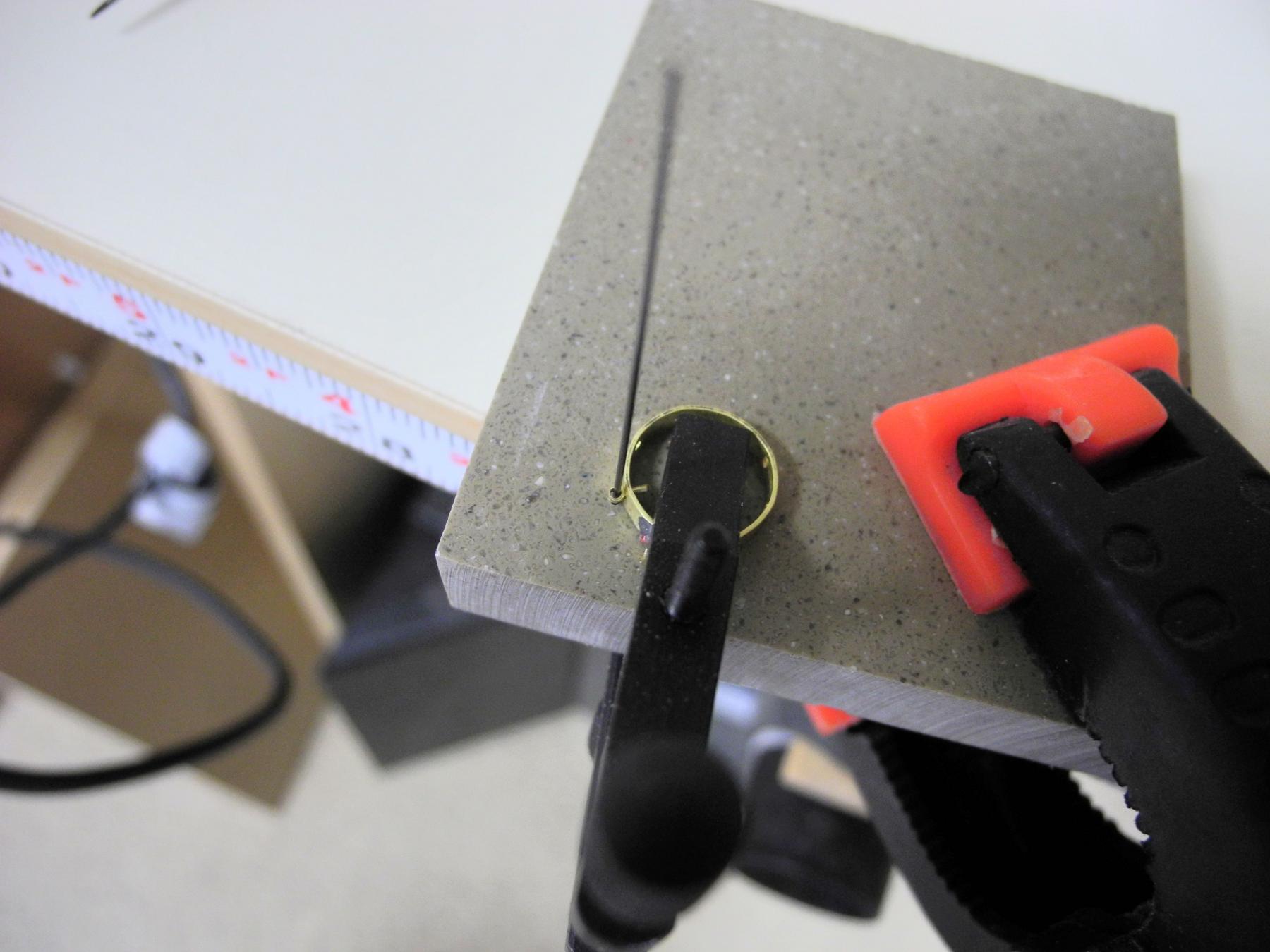
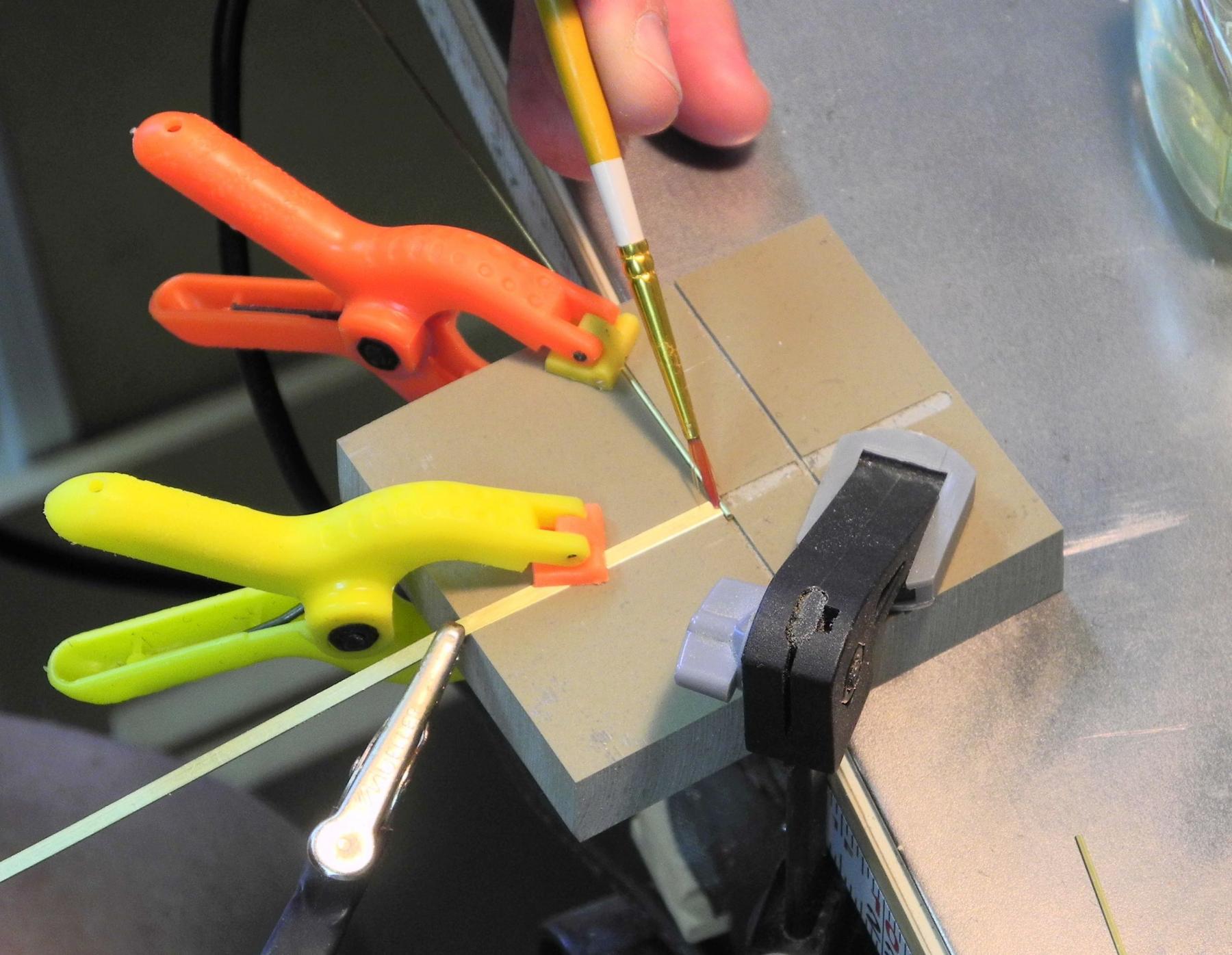
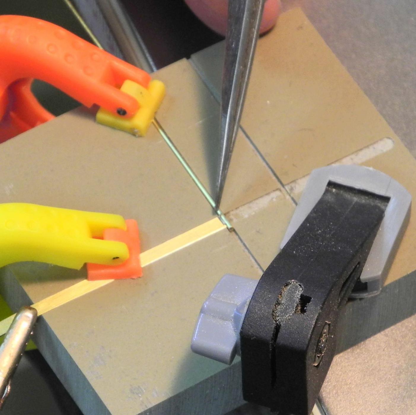
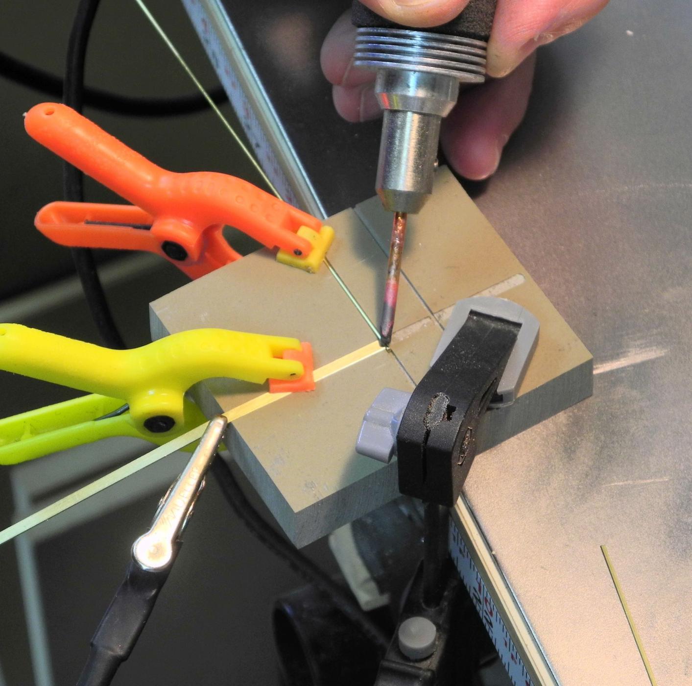
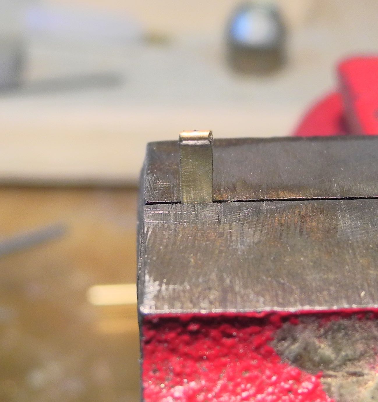
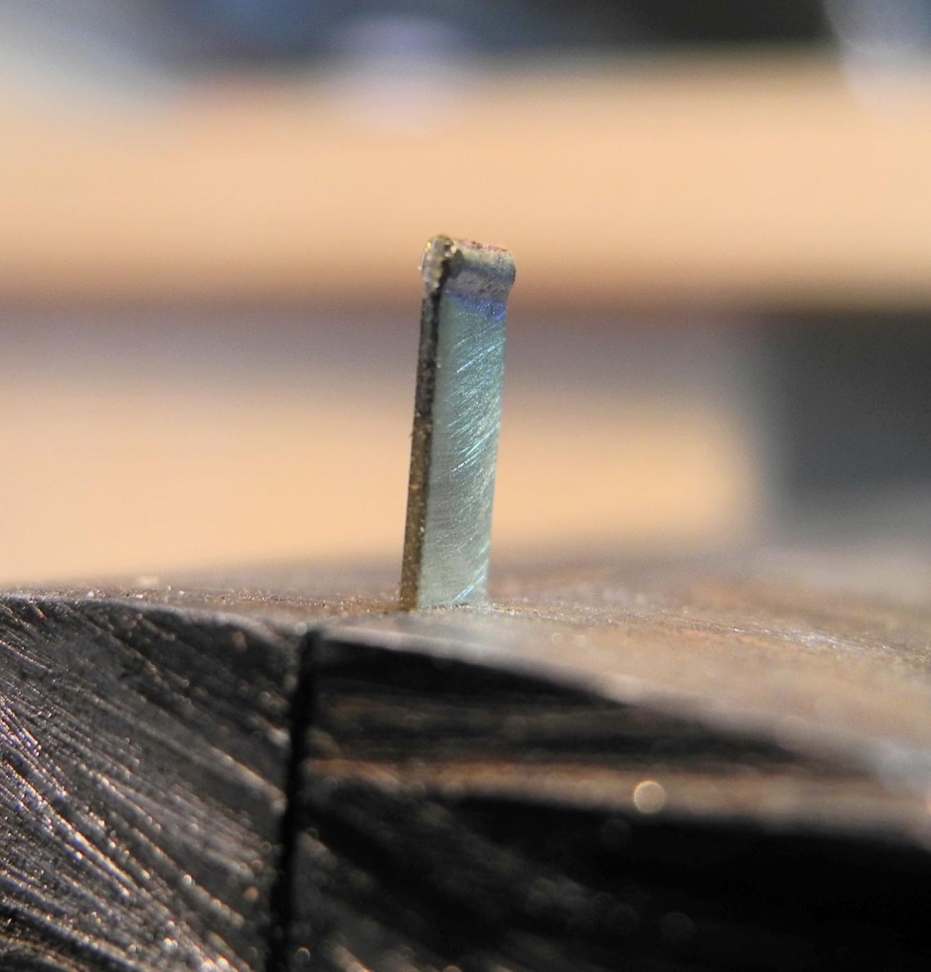
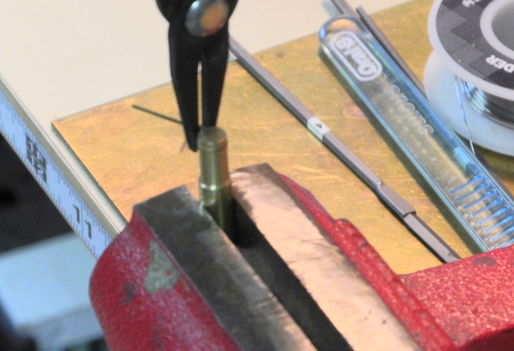
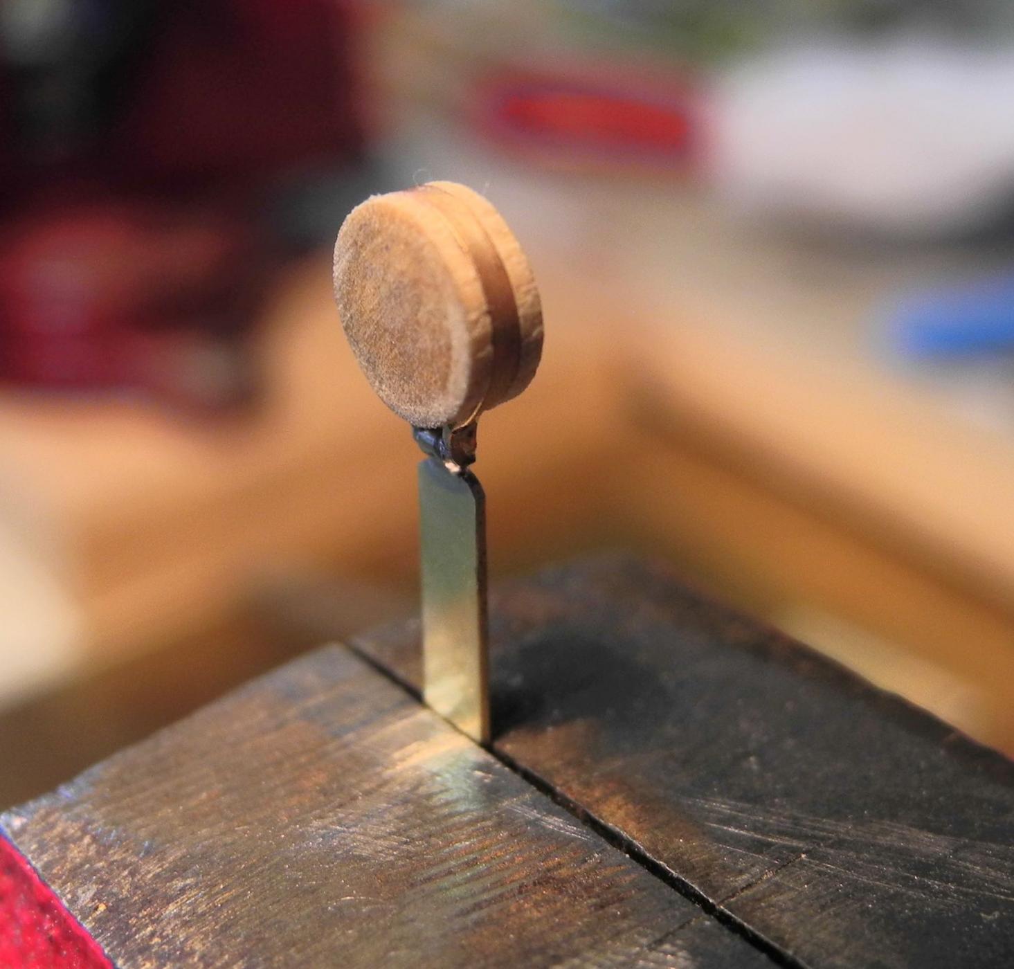
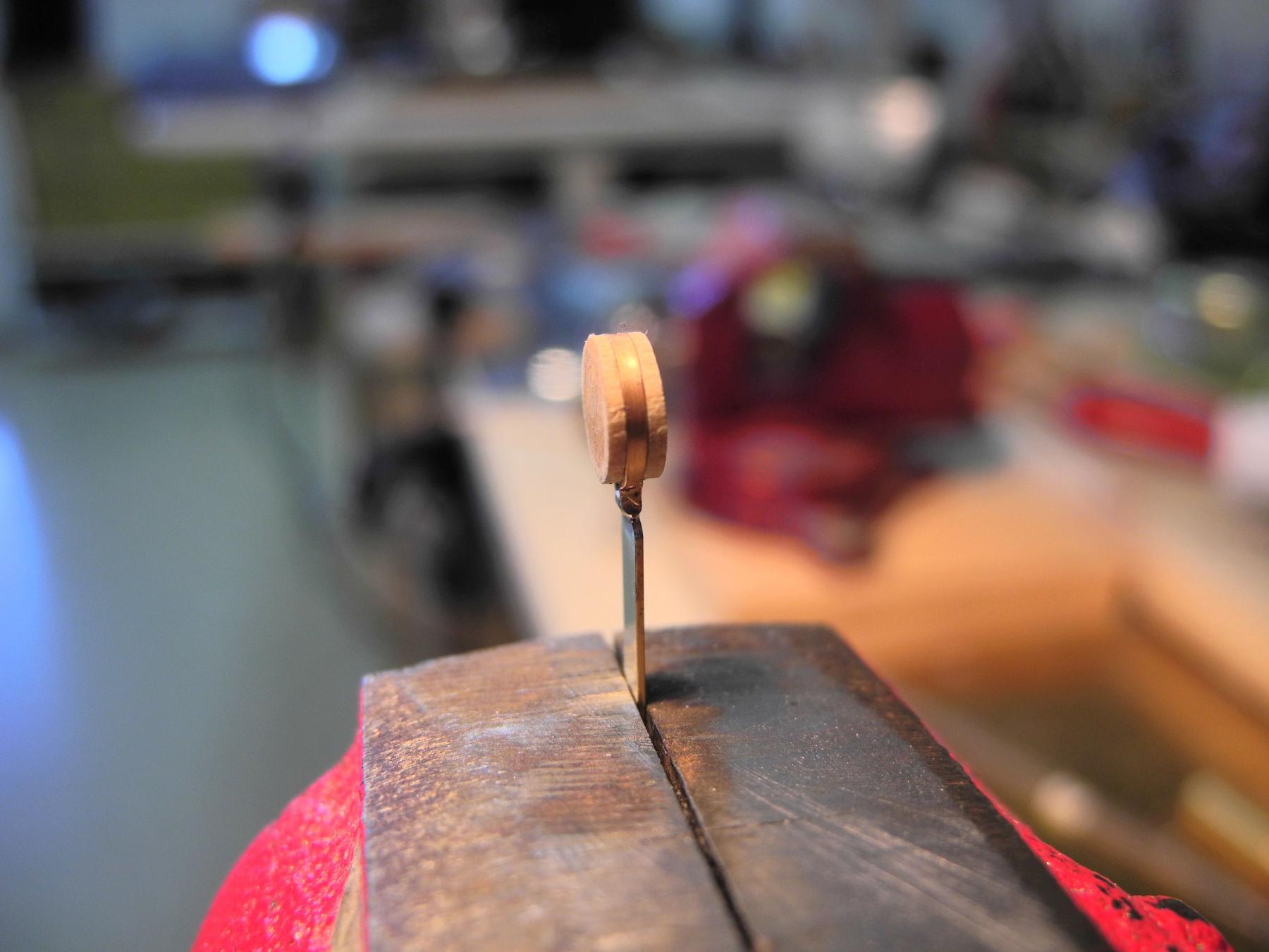
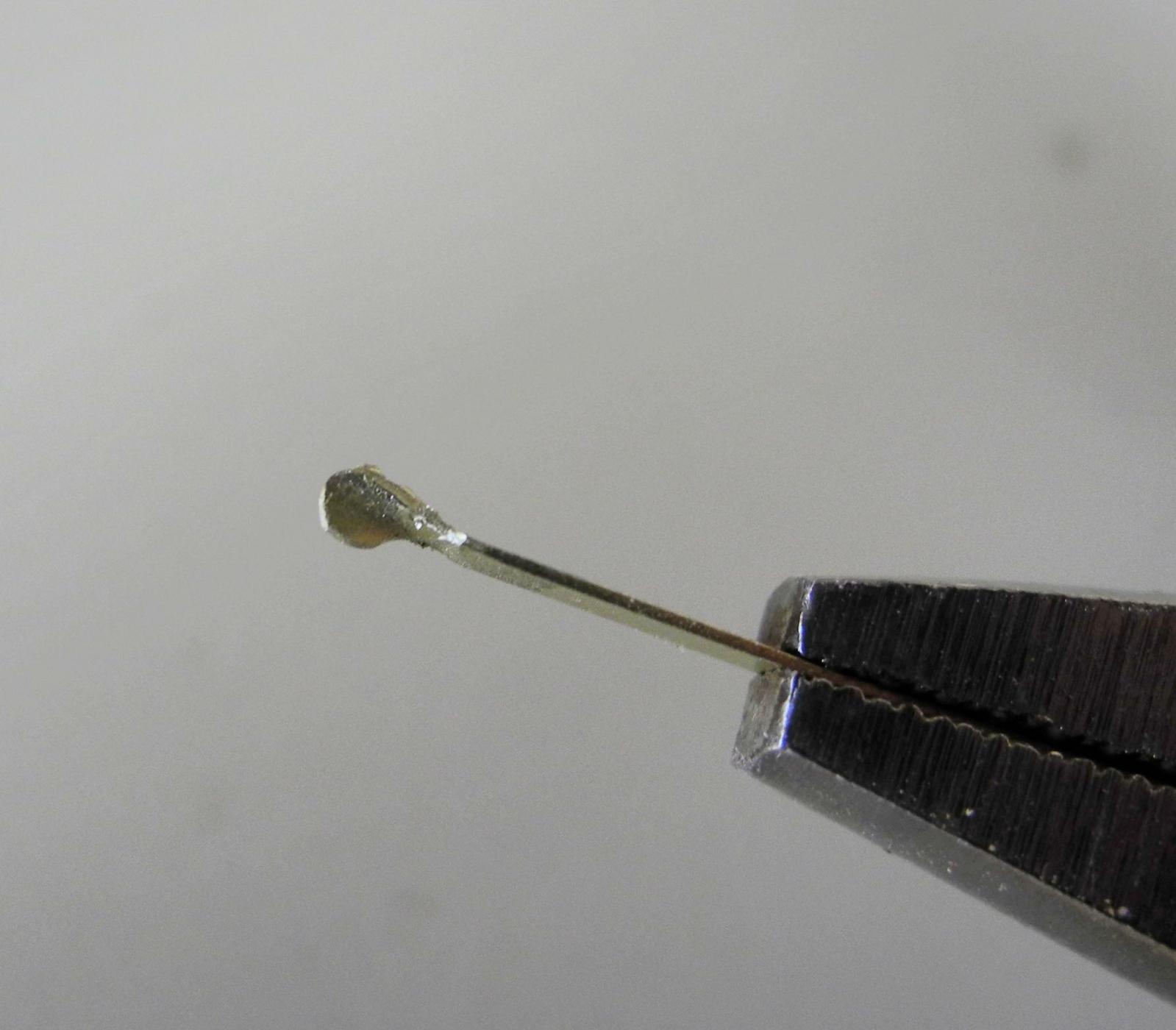
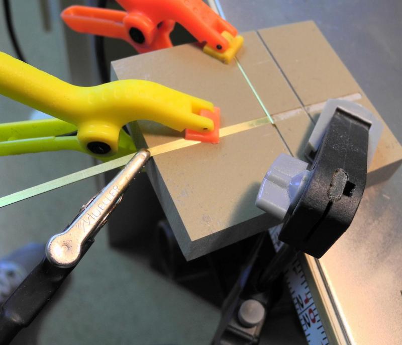
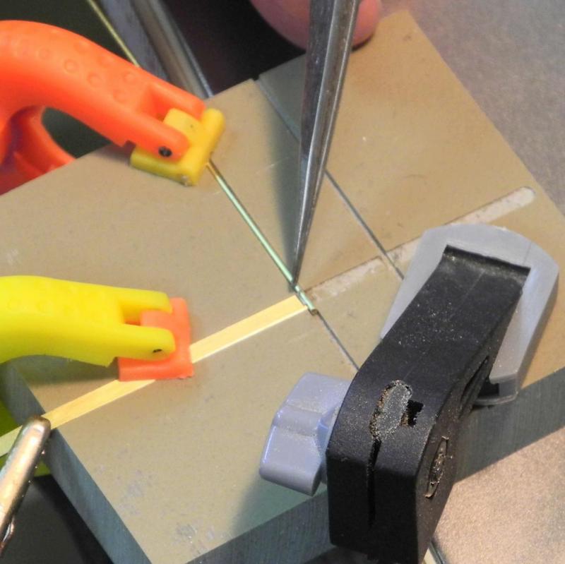
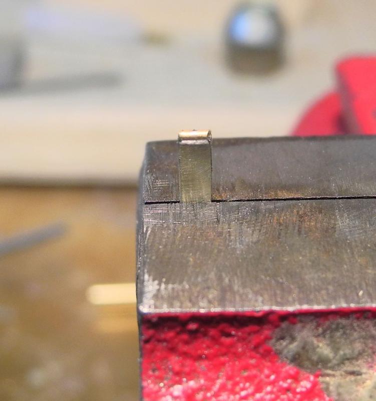
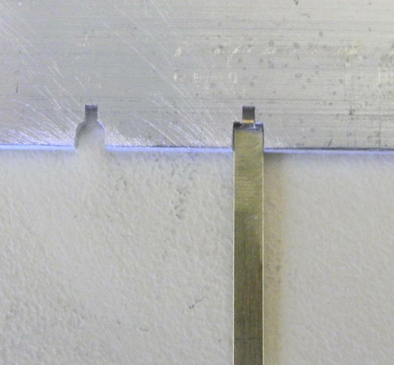
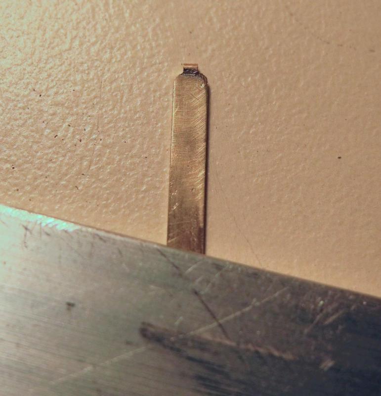
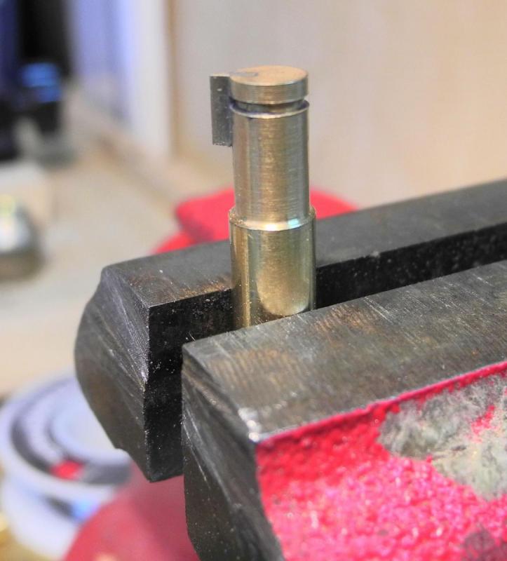
Part 49 – Deadeyes and Chainplates Version 2 I wasn’t really happy with the results of my first try at making the deadeyes and chainplates for Dunbrody. After lots of thought (much of it in the middle of the night when I should have been asleep), I decided that a couple of jigs would help with the precision. Twisting the chainplate to form the hinge, as in the prior attempt, would most likely result in a number of variances from one deadeye to another. When viewing a single deadeye the result might be acceptable, but when 6 or 8 deadeyes are lined up next to each other the differences would surely stand out. The original attempt started with soldering a piece of 1/32 round bar to the chainplate, which is 3/32 x 1/64. This gave a good impression of a hinge, but centering and shaping the hinge and the shoulders of the chainplate was problematic, and that’s when I decided to twist the chainplate stock to form the hinge. The new process starts with the round bar, and I thought some viewers may be interested in seeing how resistance soldering works. The first photo shows the soldering setup. The jig consists of a piece of corian milled so that the groove for the chainplate is the same depth as the thickness of the stock, and the groove for the round stock is the correct depth for the chainplate to lie at the center of the round stock. The large black clamp simply holds the jig on the table. The yellow plastic clamp is holding the chainplate to the jig, and the orange plastic clamp is holding the round bar stock to the jig. The alligator clip attached to the chainplate is the negative electrode attached to the resistance soldering power unit. After the setup is secured, flux is applied as in any other soldering process. I’m using Stay-Clean flux – this normally comes with Sta-Brite solder. I use a silver-bearing solder from Radio Shack, mainly because it comes as a very thin wire, so it’s easy to clip off a very small piece and avoid wasting solder and making cleanup harder. In the following photo you may be able to see the very small piece of solder pointed to by the tweezers. Heating the solder is accomplished by holding the positive electrode to the workpiece – normally at the thickest part – and depressing the footswitch. With pieces this small the soldering takes only a few seconds. The piece cools down almost immediately, so it’s not necessary to wait or to immerse the piece in a cooling bath. The next step is to clip off the excess round bar. Shaping a piece this small by eye so that it is symmetrical and repeatable is very difficult. A shaping template was made on the mill so that the piece could be tested as it was being shaped (shaping was done with a small parallel Barrette file – number 4). The square hole on the left is for the initial shaping to get the size of the hinge consistent and centered. The hole on the right was shaped using a rounded end mill and indicates the shoulders of the chainplate. The following photo shows the first step in shaping the hinge. After the shoulders were rounded the profile of the hinge is finished. The strop is a piece of 1/32 x 1/64 flat bar stock. The strop is annealed (heated to a red color and then quenched) to soften the stock and make it easier to bend. During my first attempts I bent the strop around the deadeye itself. This resulted in the strop being completely around the deadeye with little or no room for the hinge arrangement. I decided to make a bending jig that would ensure a sufficient opening in the strop. This jig consists of a piece of round brass stock shaped to the proper diameter on the lathe and with a groove cut in for the strop. It also has a piece of flat stock of the same thickness as the hinge soldered into a slot that was cut into the jig. The strop is bent around the jig and tightened by squeezing the ends to the protruding piece. The strop is then added to the deadeye and the assembly is placed in the jig for forming the assembly (same jig as previously used). The deadeye being used in the picture has been used in several previous attempts, so is discolored. This won’t be an issue when the ‘production’ deadeyes and chainplates are being assembled. The ends of the strop are then clipped down to the finished length and the protruding ends are rounded. The chainplate is then soldered to the deadeye hinge, using the setup shown in the following photo. I’m much happier with the results of this new process. Making a single deadeye/chainplate combination takes less than an hour with this new process, and is very repeatable. The shaping definitely requires the use of an Optivisor, since these deadeyes are fairly small. So now I guess I’d better start making the ‘production’ deadeyes before I forget how! Thanks, everyone!


- 649 replies
-
- 24
-
-
- dunbrody
- famine ship
- (and 2 more)
-
Hi Bob - the drilling approach was what I first considered, but quickly decided it was not in the cards for me. Center drilling a piece of 1/64 round stock isn't something I want to play with right now! Most of the other steps (which will be shown in my next post) would still be the same. Thanks Alan - more to come!!
- 649 replies
-
- 6
-
-
- dunbrody
- famine ship
- (and 2 more)
-
Thanks Ed. There were some really outstanding models at the conference and they made me realize that I still have lots of room for improvement. As I said above, I'm not too happy with these first attempts at chainplates. I spent some time last night thinking of some better ways to hold and form the brass (at 3 AM instead of sleeping!), and will be trying them out in the next couple of days. The use of corian for jigs was an idea I got from a modeler friend, and it's a really good one. I visited a local kitchen counter shop and asked them if I could go through their scrap bin. Corian cuts with the band saw, and mills nice and clean.
- 649 replies
-
- 8
-
-
- dunbrody
- famine ship
- (and 2 more)
-
Thanks Carl. Since I'm using resistance soldering the heat is very localized and the wood doesn't burn. The prototype has a little char because it was used several times and some of the fluxing and soldering wasn't too precise. Since I posted the latest update I've been thinking of some ways to get improved precision in fabricating the chainplates and will continue the experimenting over the next few days. Hi Druxey. I'm using a silver-bearing solder (from Radio Shack) and other joints I've made with it are quite strong. That being said, there won't be any tension on these joints since the model won't be rigged. There will only be the lower deadeyes showing.
- 649 replies
-
- 6
-
-
- dunbrody
- famine ship
- (and 2 more)
-
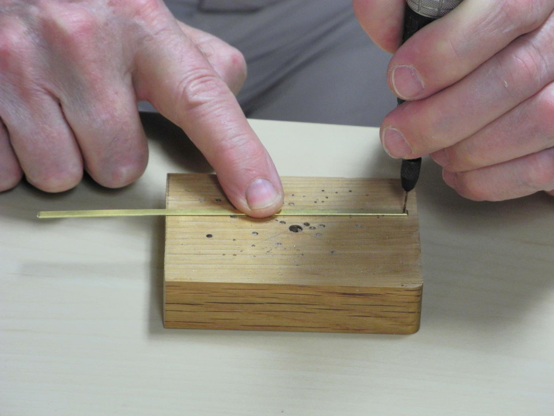
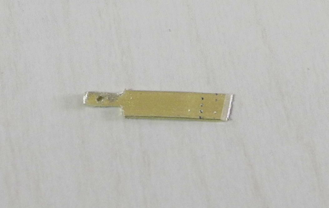
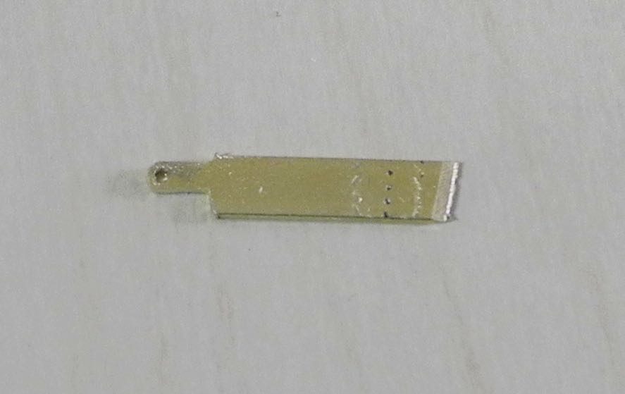
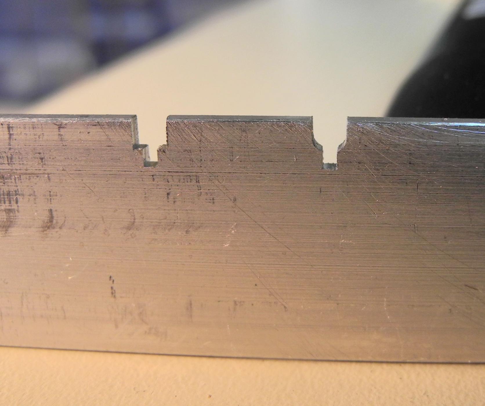
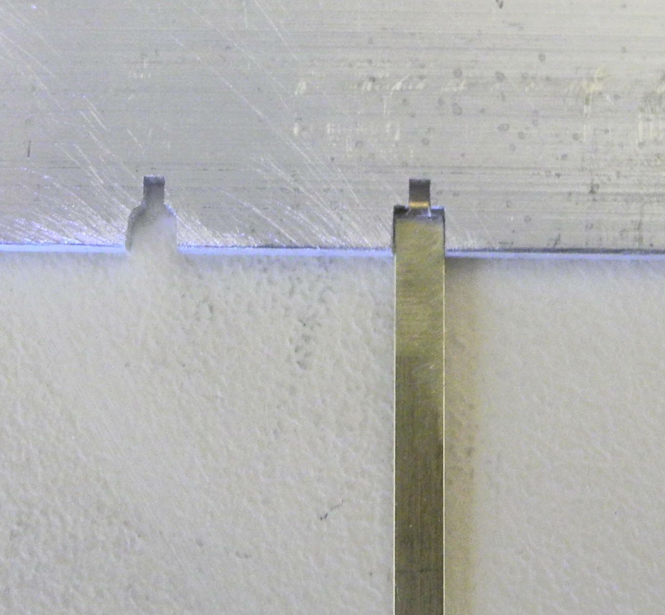
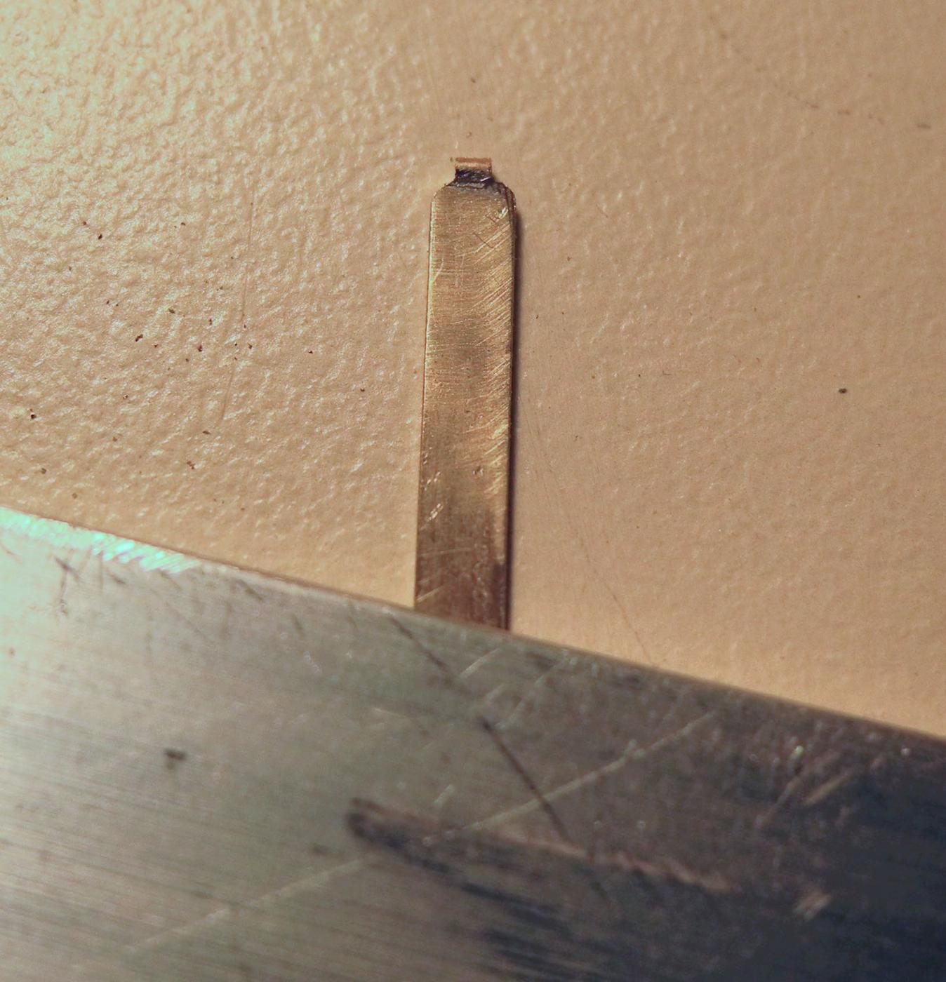
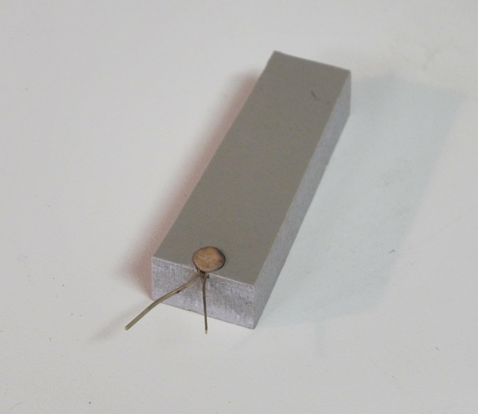
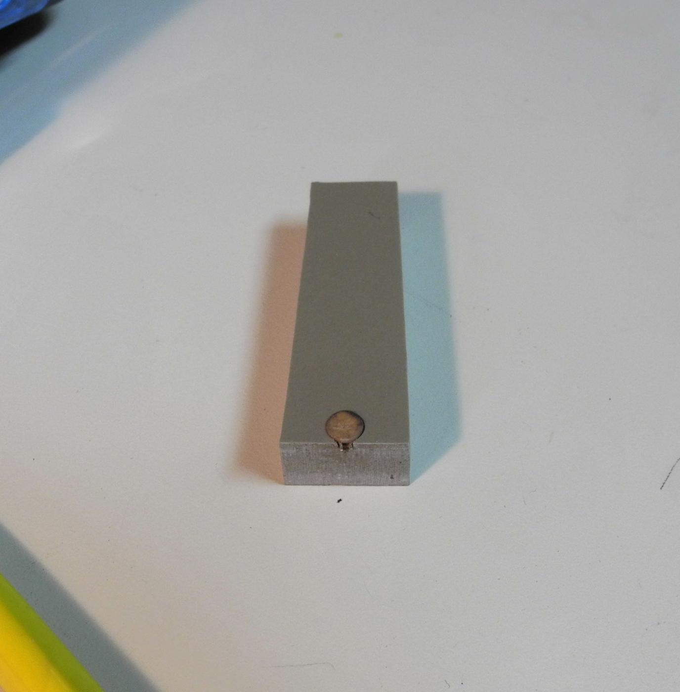
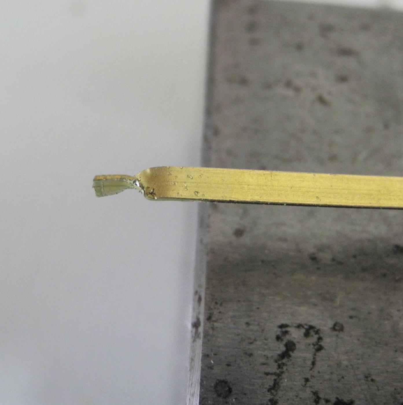
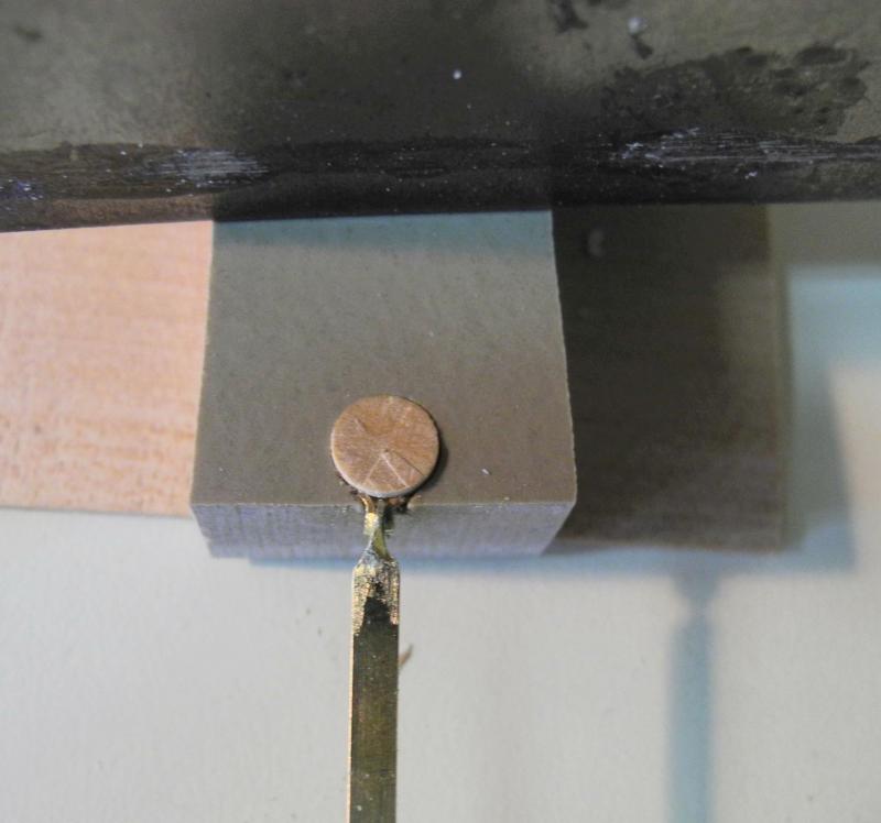
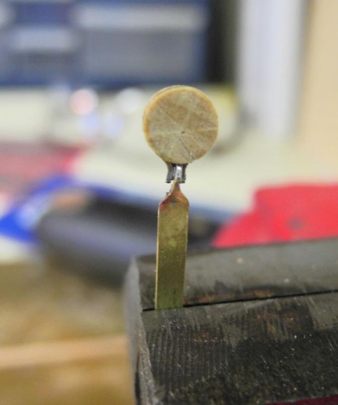
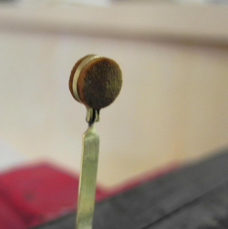
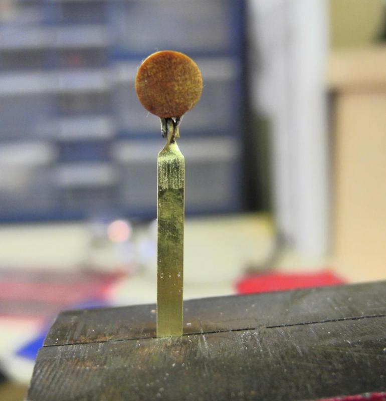
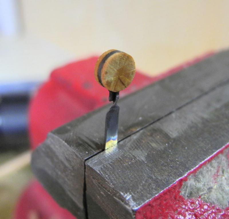
Part 48 – Deadeyes and Chainplates Well, I’m back from the NRG Conference. There were parts of it that were very enjoyable, especially the sail on the Californian, a replica of a Revenue Cutter based on a ship from the mid-1800’s. There were some really nice models on display at the conference, and it was good to meet some of the modelers I’ve gotten to know through MSW. After returning home over the weekend I spent a few days catching up on some chores that I’ve neglected. The last few weeks (or months?) have been focused on trying to get Dunbrody to a point that would make a decent display, and a lot of chores had piled up. So now I’m ready to get back to work on Dunbrody. I’ve decided to try making the deadeyes and chainplates. The deadeyes that can be seen on the replica ship are somewhat different from those I normally see. The deadeyes are stropped with a flat iron band, and the deadeyes are fairly flat all the way to the outer edges. I spent the day experimenting with some alternative ways to model the chainplates. The deadeyes are 10.5” in diameter (7/32 on the model), based on the rule of thumb that they should be ½ the diameter of the associated mast. The trial deadeye was turned from a piece of castello. A lathe tool was shaped for cutting the flat depression for the stropping band. The iron stropping band is made form 1/32 x 1/64 flat brass stock annealed to make the bending more manageable. A holding jig was made on the mill from a scrap piece of Corion – this is a material used for countertops, and is a good material for soldering jigs. This jig has a hole the same size as the deadeye, and a small channel for the ends of the strop to protrude. As can be seen from the photo, the deadeye has not yet been drilled for lanyard holes, nor has it been smoothed after coming off the lathe. It was parted using a small razor saw, so normally these deadeyes would be finish-sanded. Since this was a prototype those steps were omitted. The ends of the strops were cut down to the final length, and were rounded. This work was done with a high-speed rotary tool. The chainplates will be made from 1/8 x 1/64 brass strips. I started by soldering a 1/32 round bar to the end of the strip, to simulate the hinge that attaches the strop to the chainplate. I made a jig with a rounded groove for the round bar to sit in and a 1/64 groove for the strip to sit in. The jig worked well, and since I use resistance soldering I was able to hold the strip to the jig with a plastic clamp with no heat-related problems. Unfortunately, the round hinge made it very difficult to connect the deadeye to the chainplate. After a lot of frustration, I tried a different approach. The end of the brass strip was twisted 90 degrees. It was then smoothed and shaped using the rotary tool with a diamond bit. The chainplate was soldered to the deadeye using the holding jig to keep everything aligned. A final shaping was done for the deadeye/chainplate combination. JAX brass cleaner was used to clean off the chainplate. After using the cleaner the whole assembly was cleaned under running water. This soaked into the wood of the deadeye, but dried to a natural color. After cleaning, the assembly was blackened using JAX Pewter Black and was rinsed again in cold water. The wood was still wet when these photos were taken, but the deadeye again dried to a natural color. The real deadeyes will be darkened with stain or paint before installation, so any kind of discoloration would not be a problem in the finished deadeyes. The photos show some lack of symmetry, but the assemblies look good to the naked eye (without magnification!). When the real deadeyes are made I’ll take more time to get them as symmetrical and smooth as possible. I still like the idea of the rounded hinge better than the successful approach, so I’ll continue to play with that alternative for a while. Thanks everyone!


- 649 replies
-
- 21
-
-
- dunbrody
- famine ship
- (and 2 more)