Mahuna
-
Posts
1,504 -
Joined
-
Last visited
Content Type
Profiles
Forums
Gallery
Events
Everything posted by Mahuna
-
 Thanks Bob. I always appreciate seeing photos of work progression on other build logs, so I thought I should do the same.
- 649 replies
-
- 5
-

-
- dunbrody
- famine ship
- (and 2 more)
-
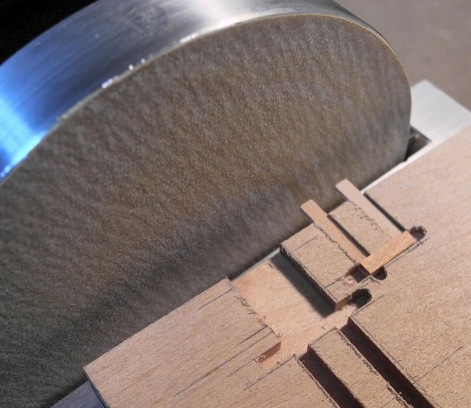
Very nice, Ed. I especially like the way you sliced off these very small parts, particularly using the sacrificial fence. I imagine that helped to keep those very small pieces from flying off.
- 3,618 replies
-
- 5
-
-
- young america
- clipper
- (and 1 more)
-
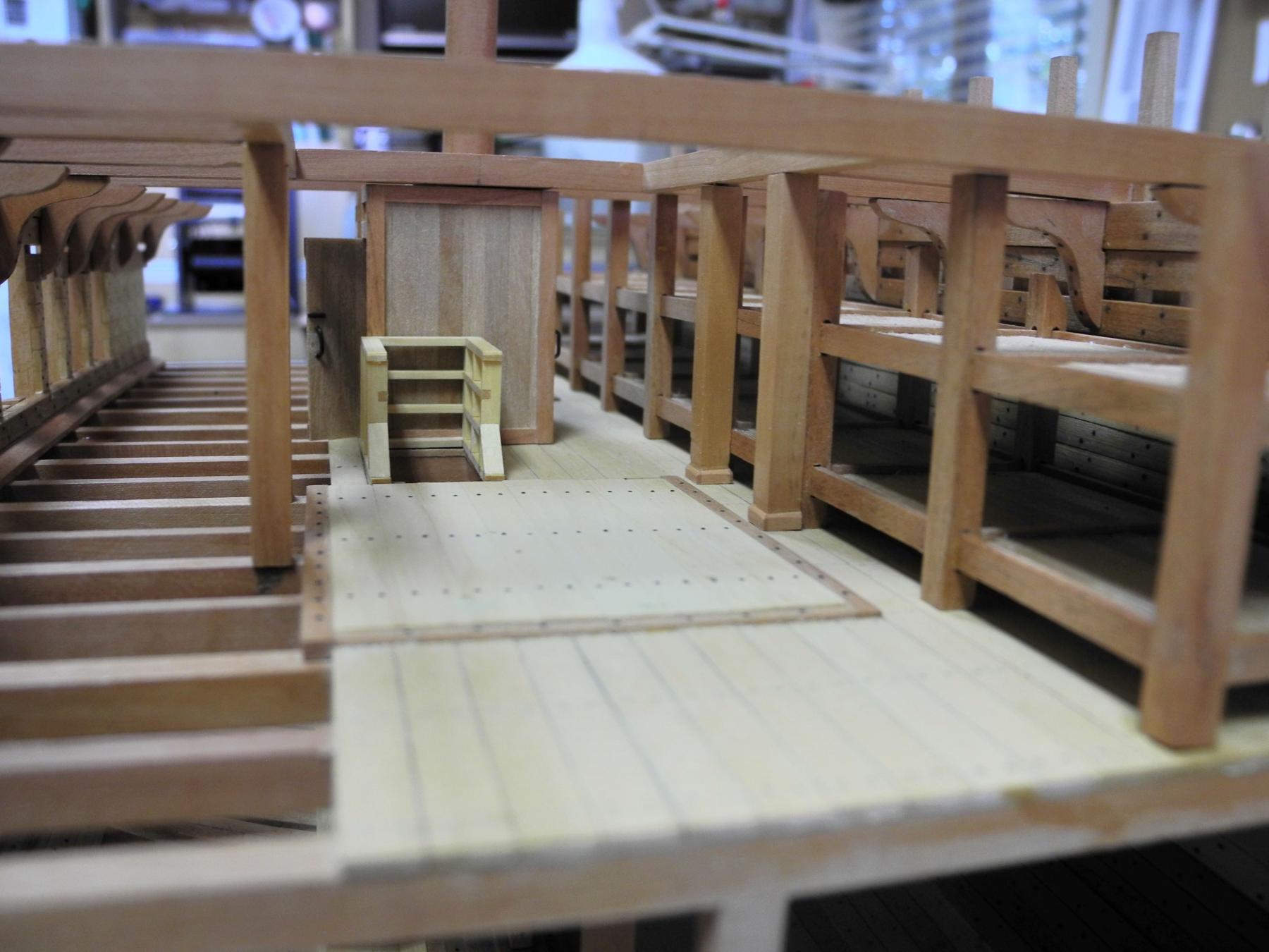
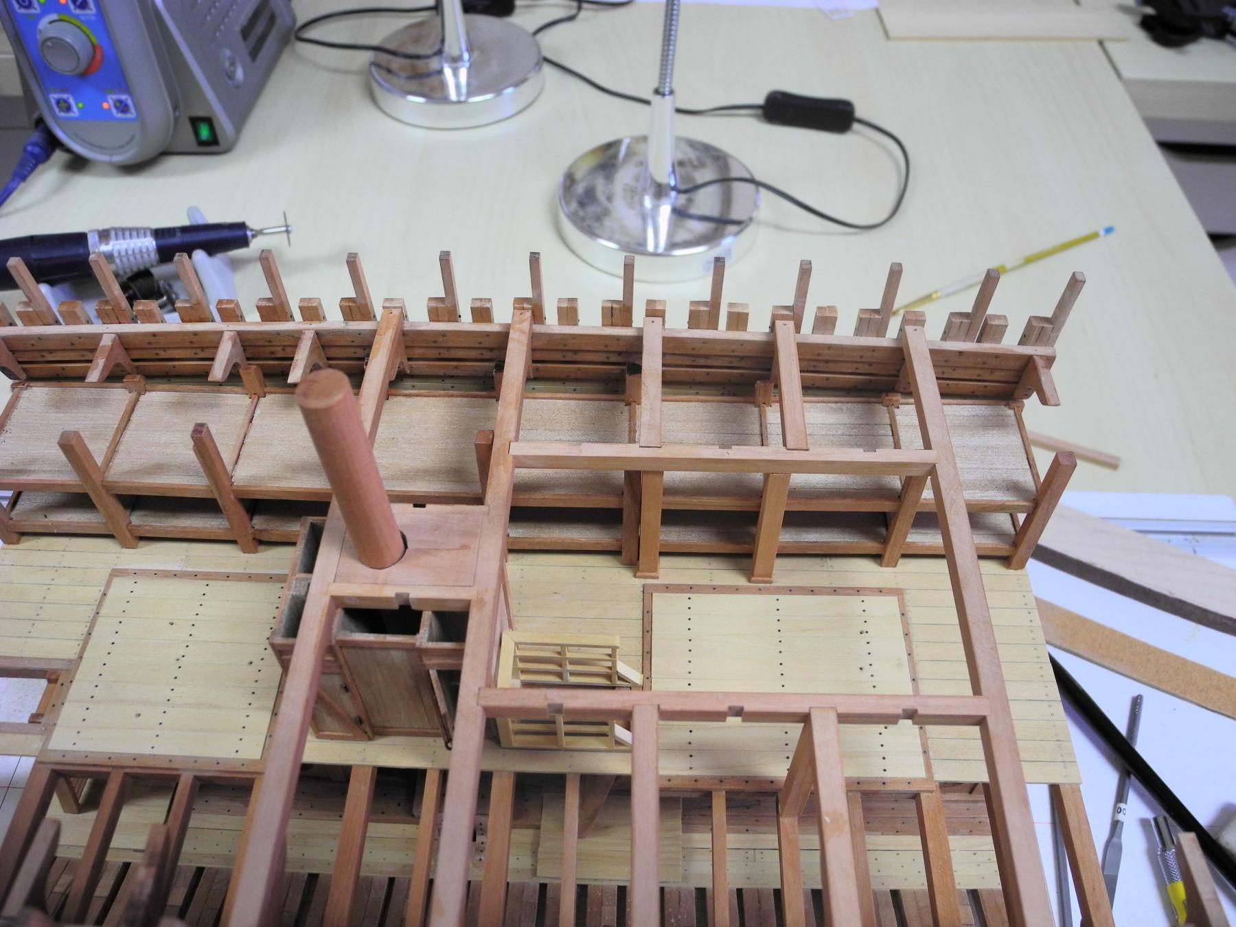
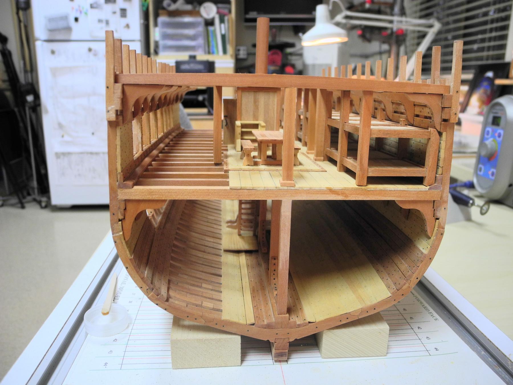
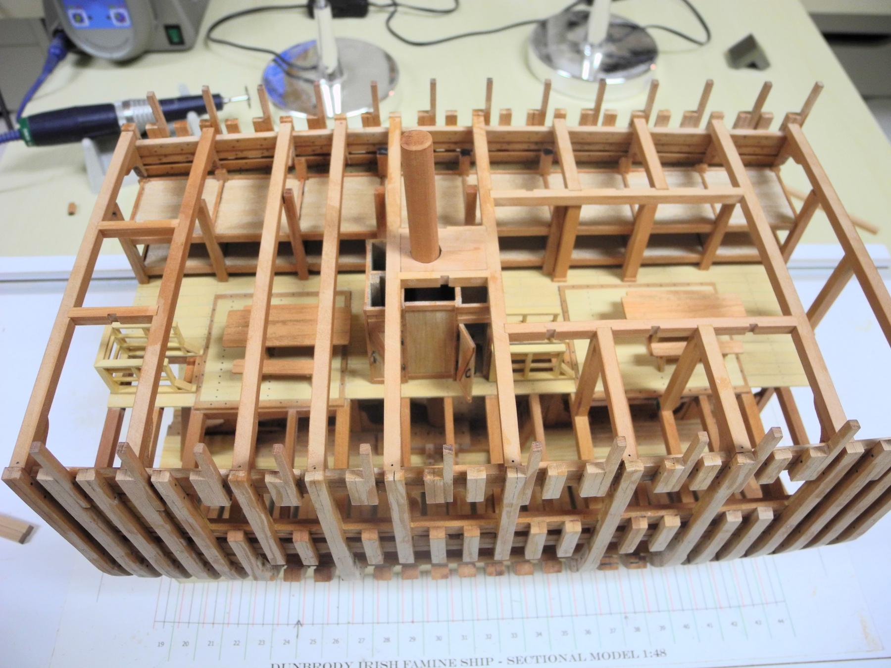
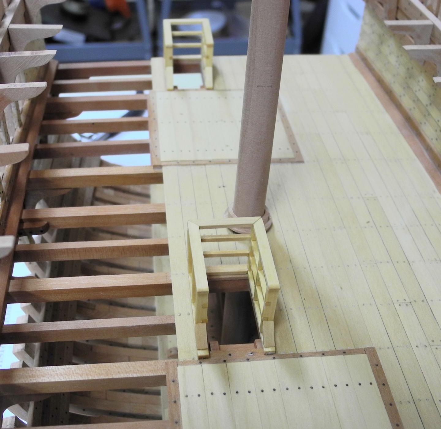
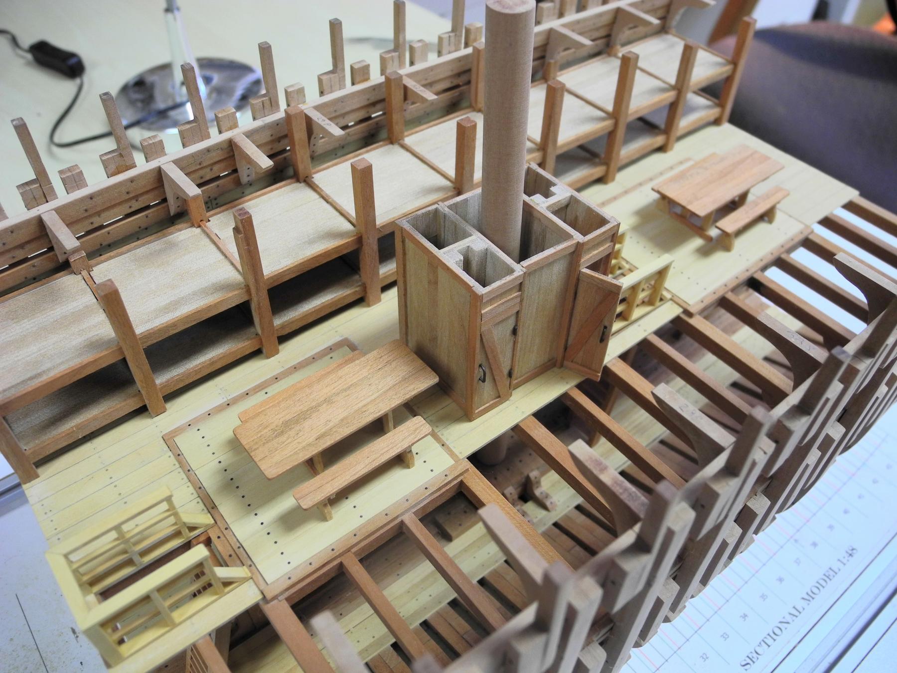
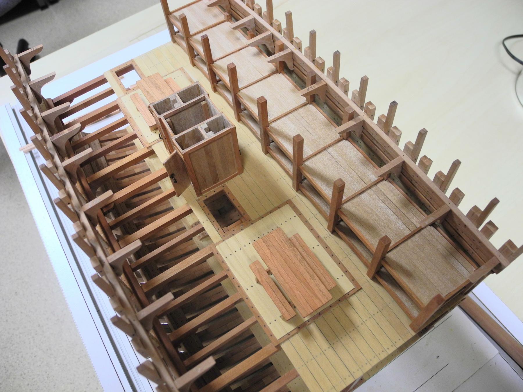
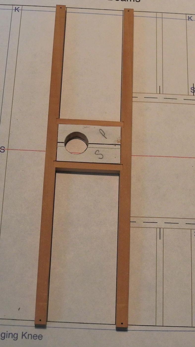
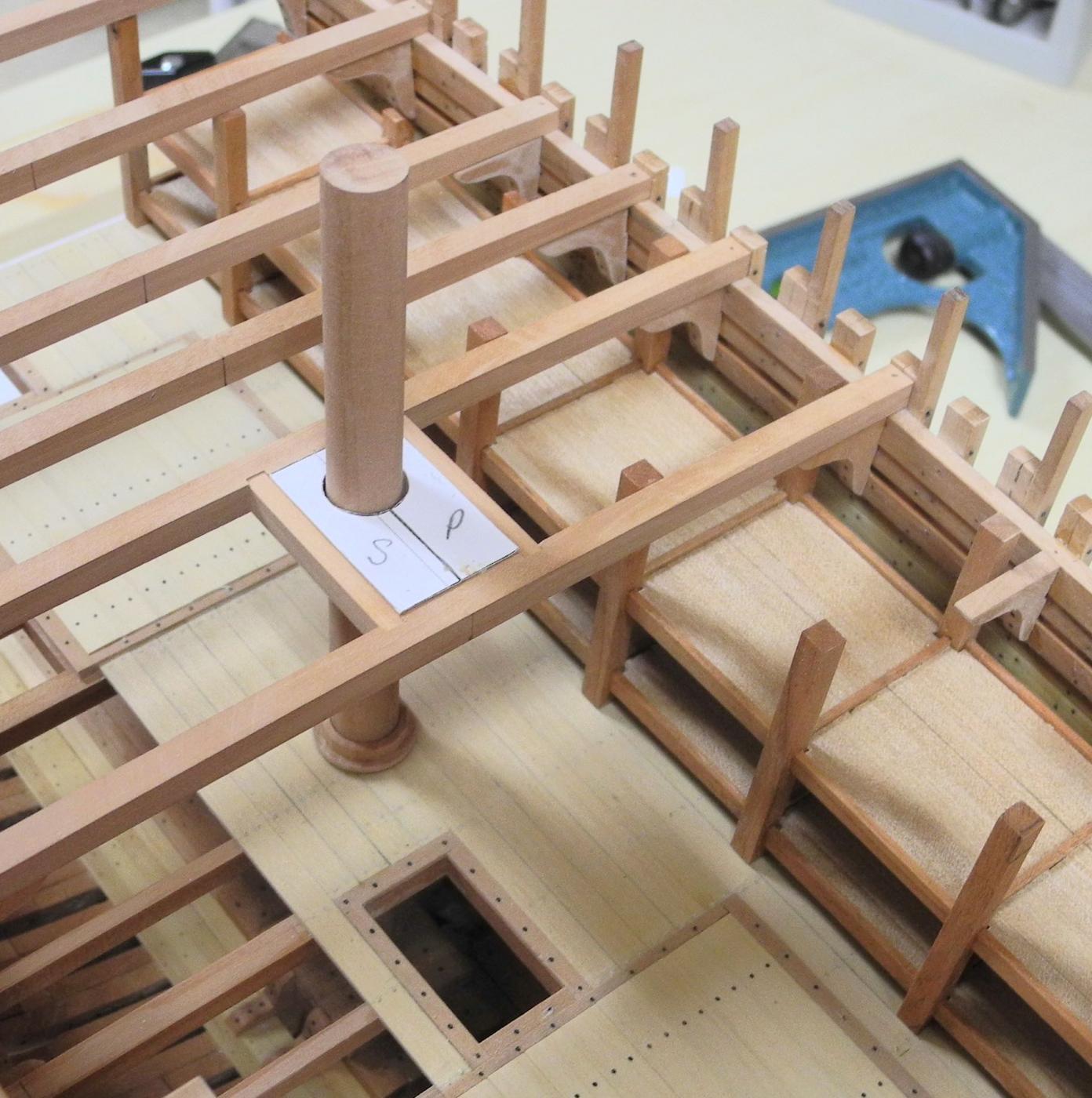
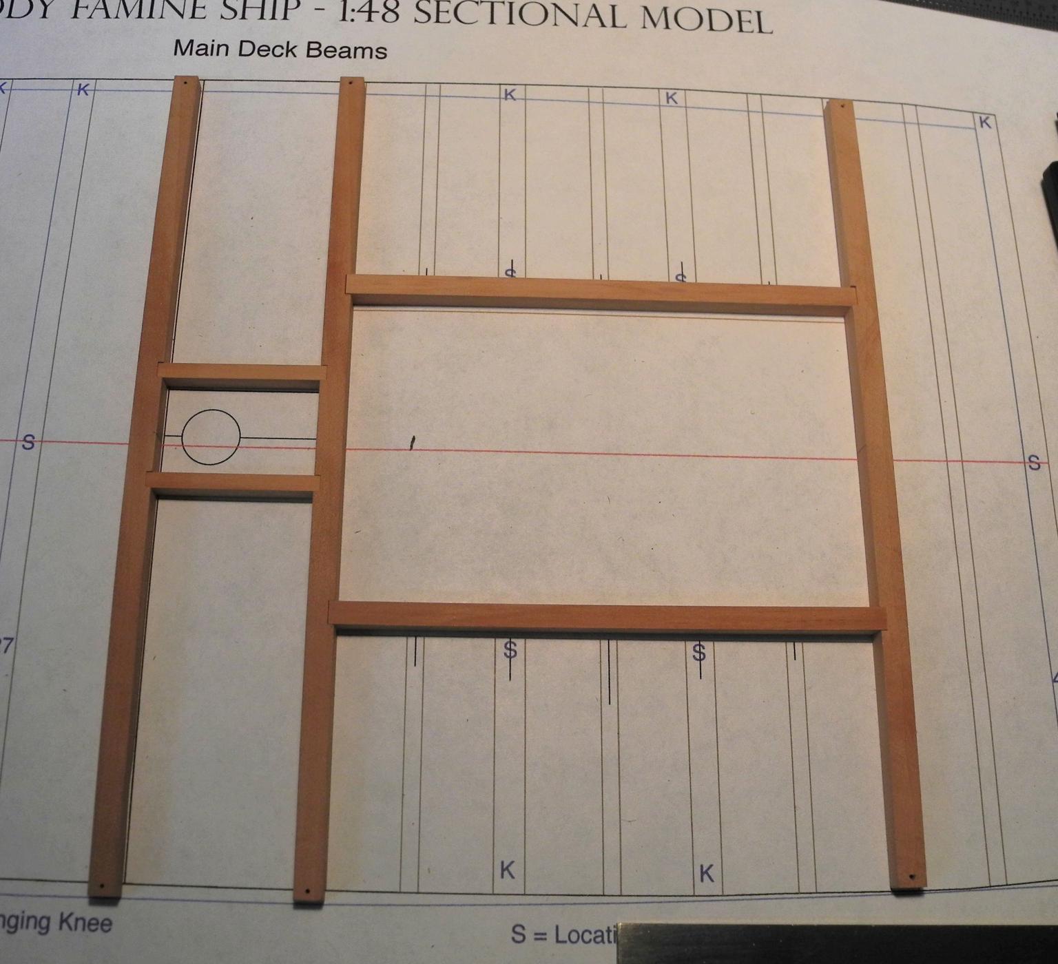
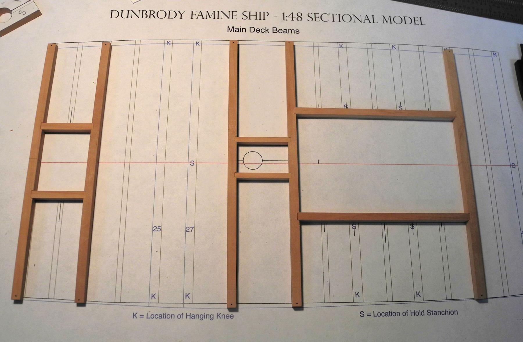
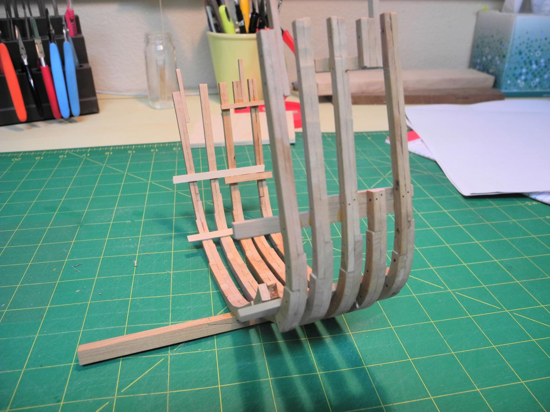
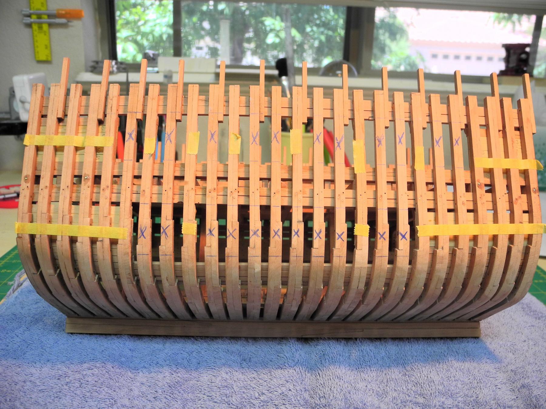
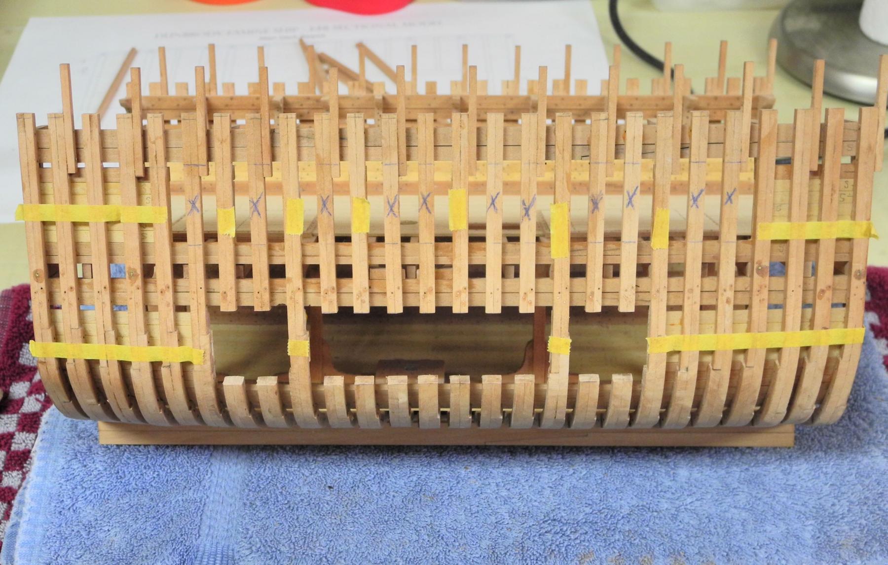
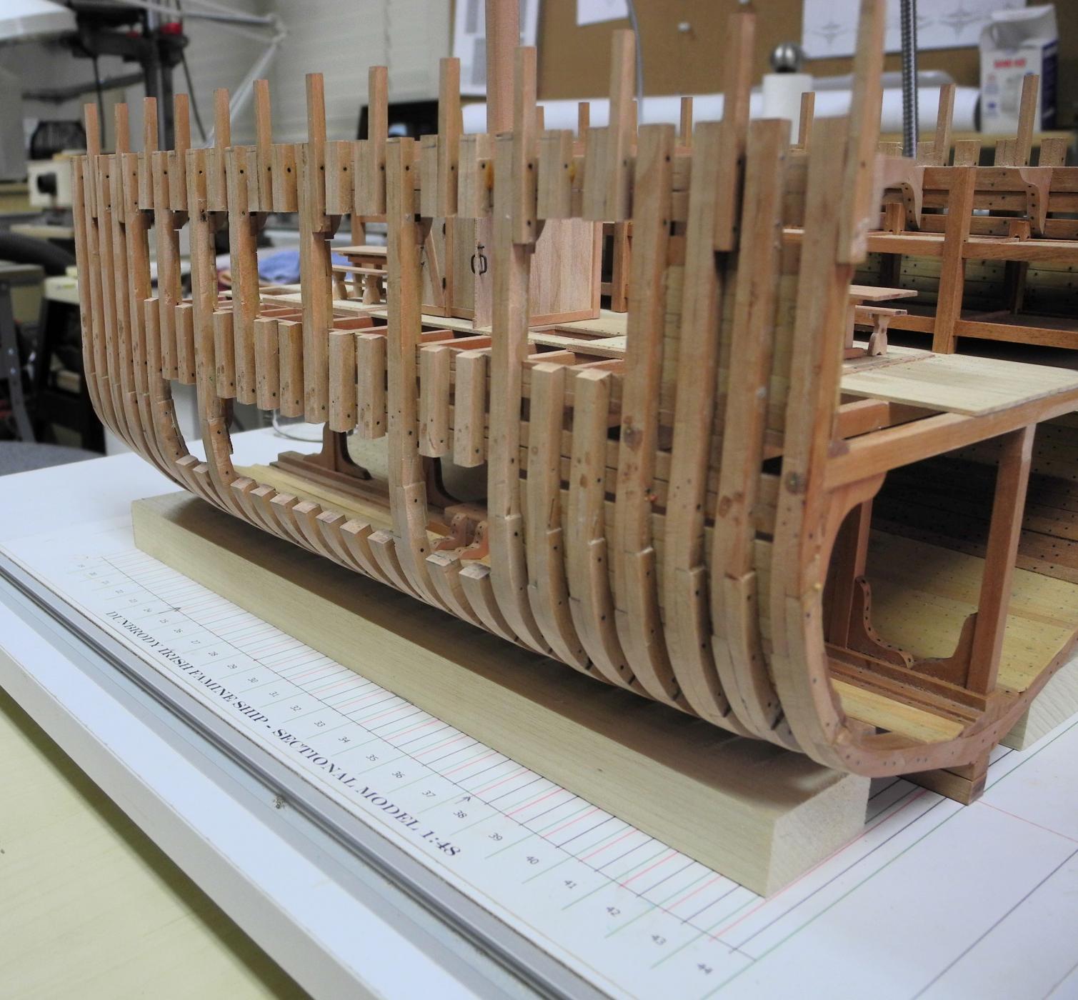
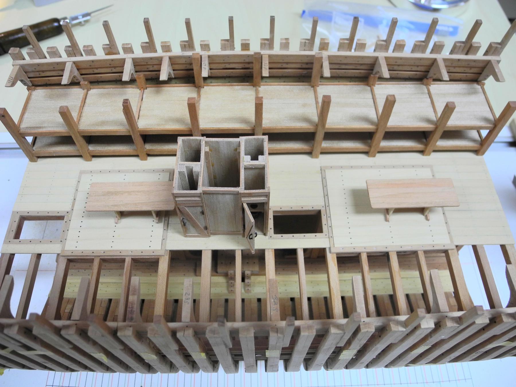
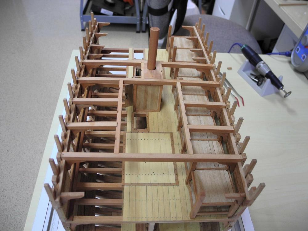
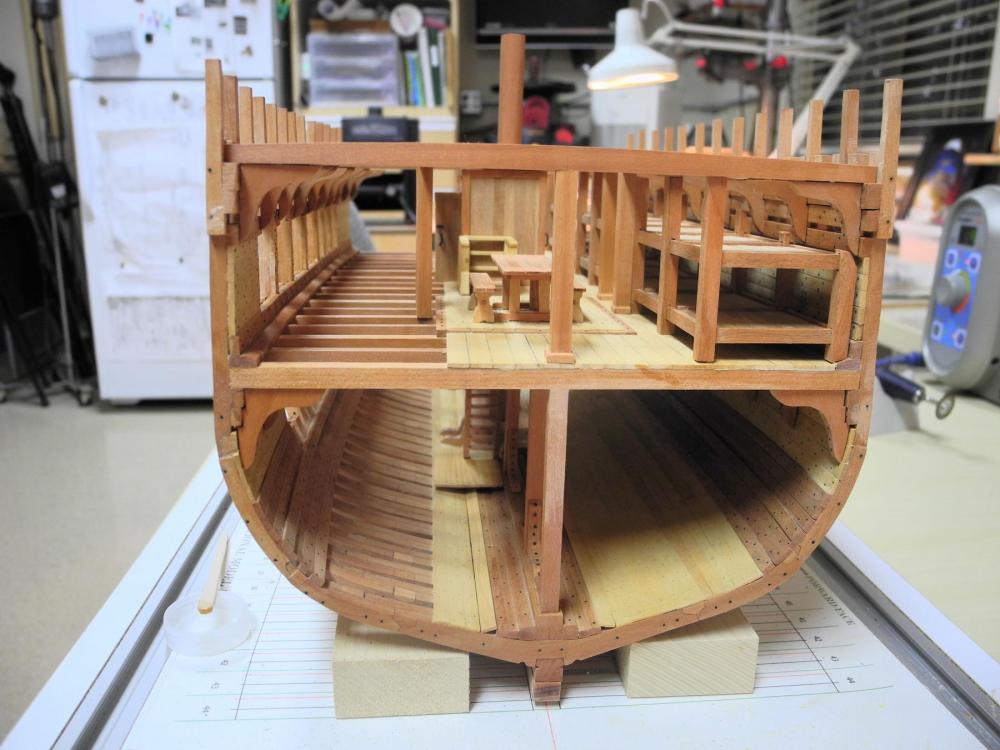
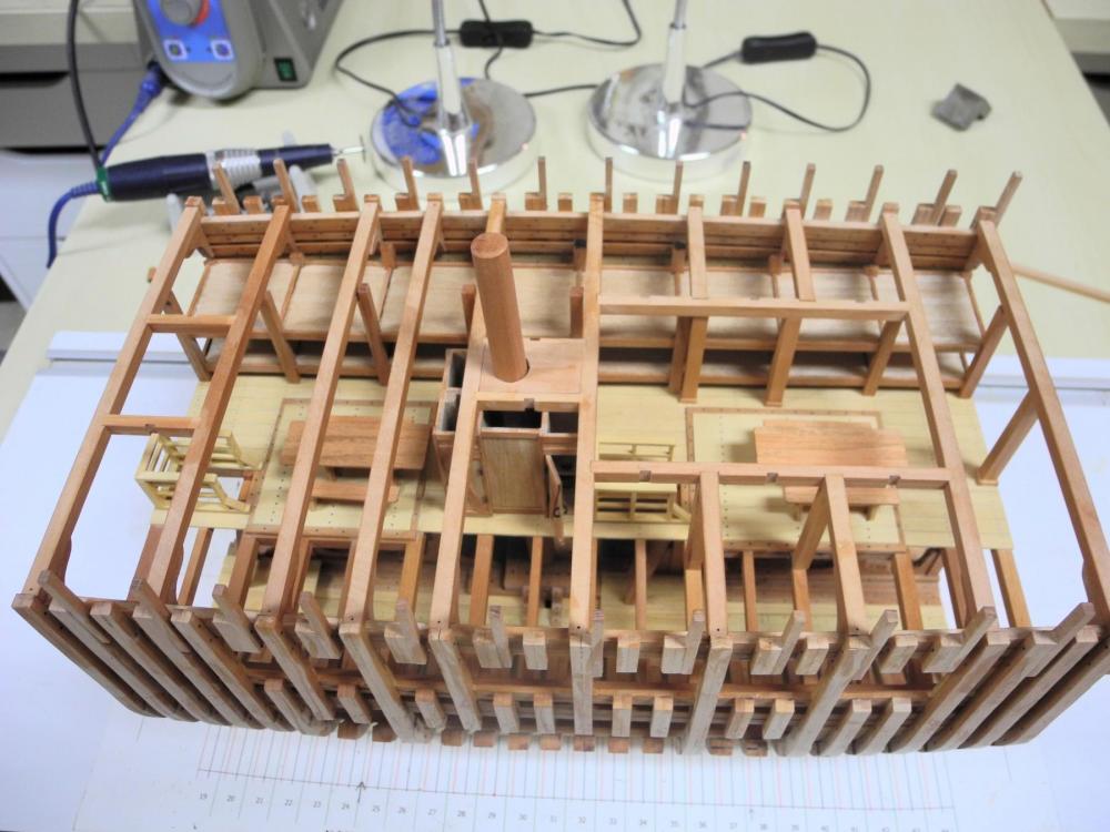
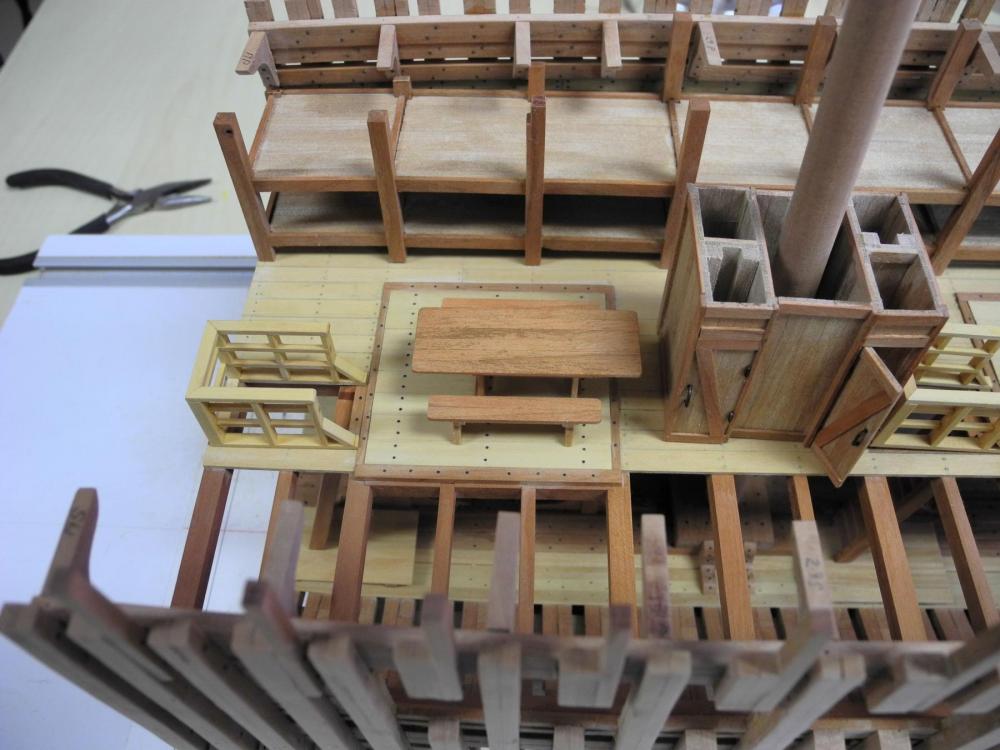
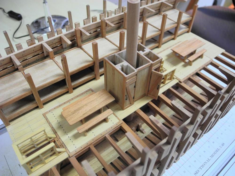
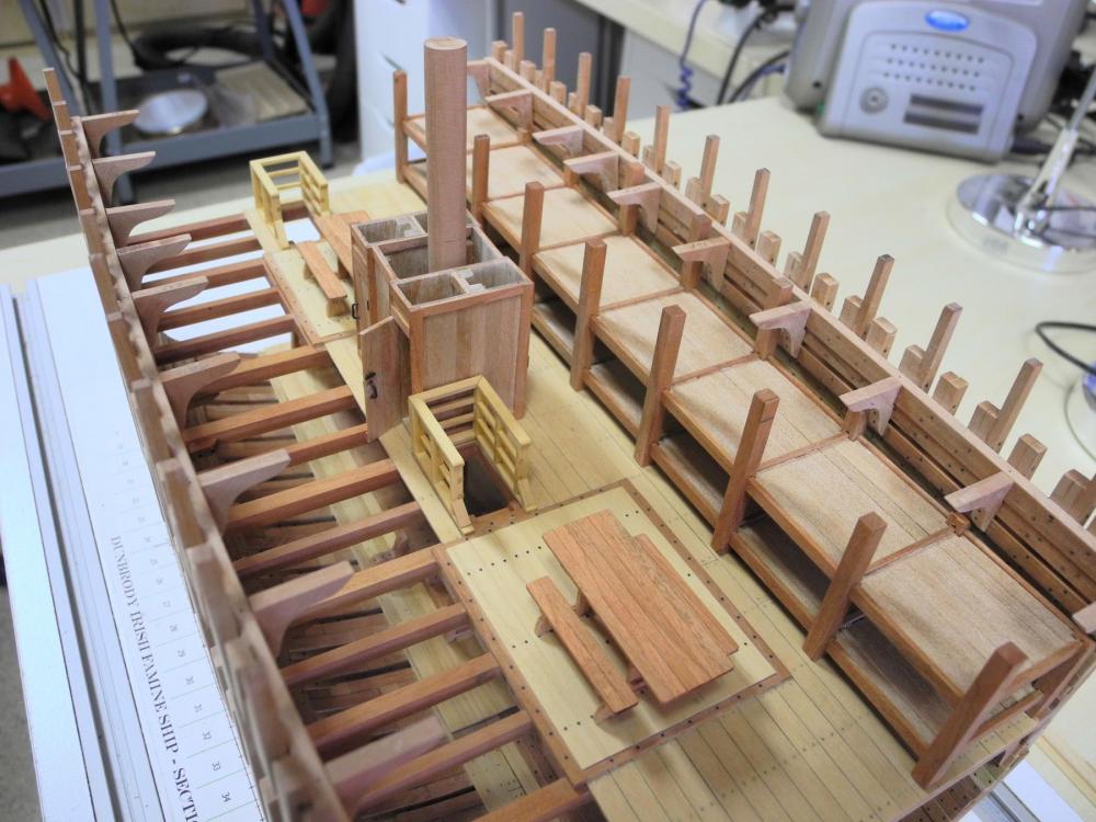
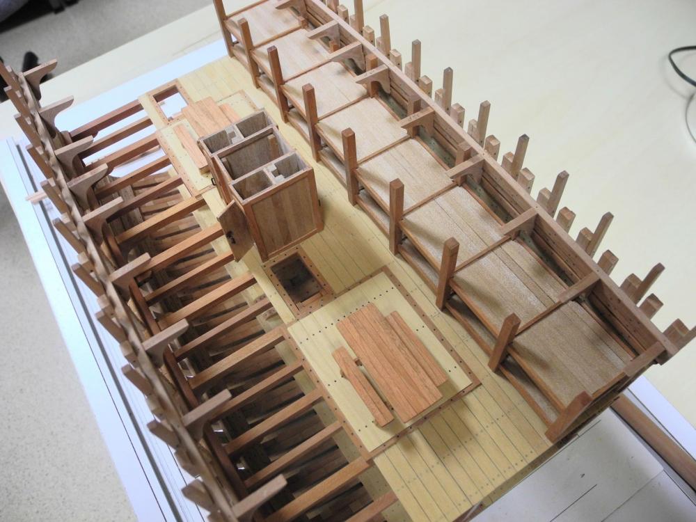
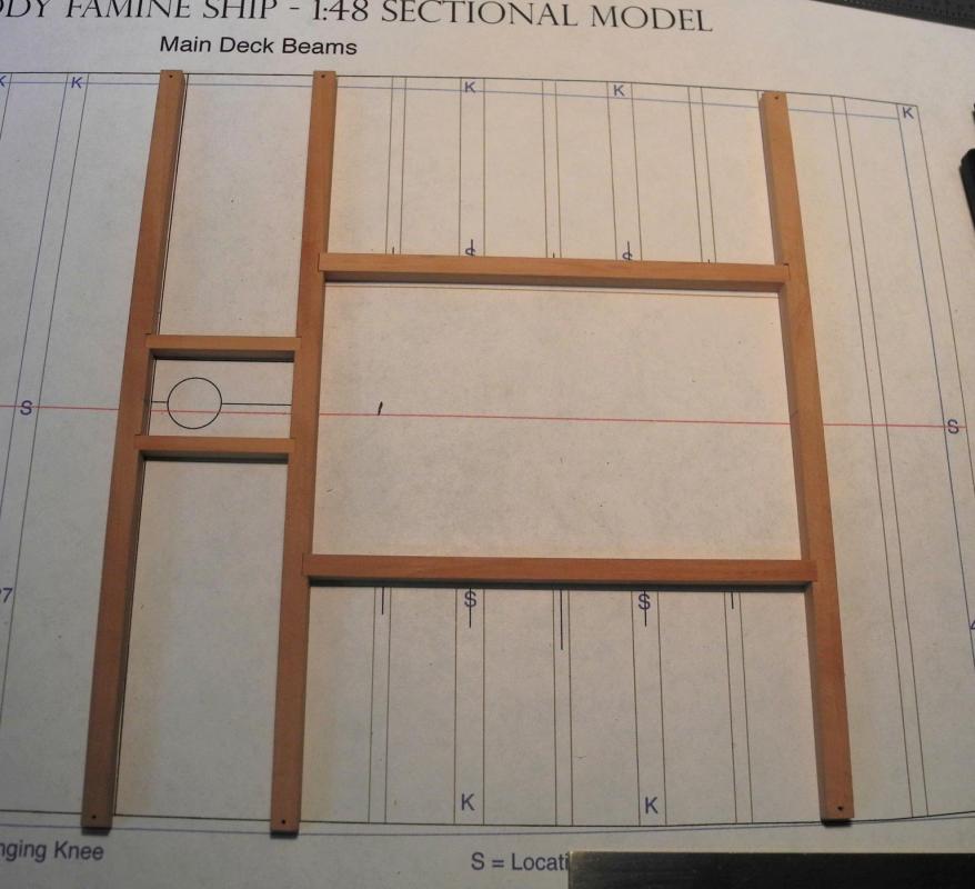
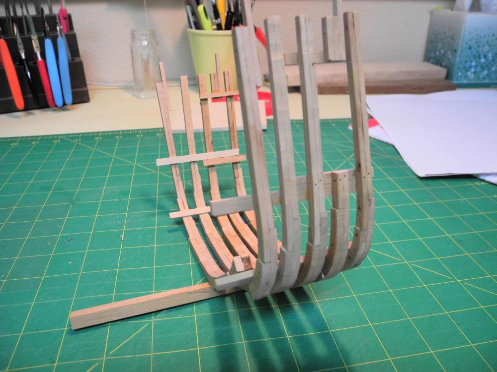
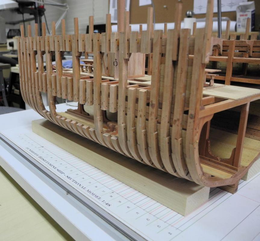
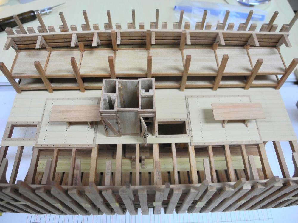
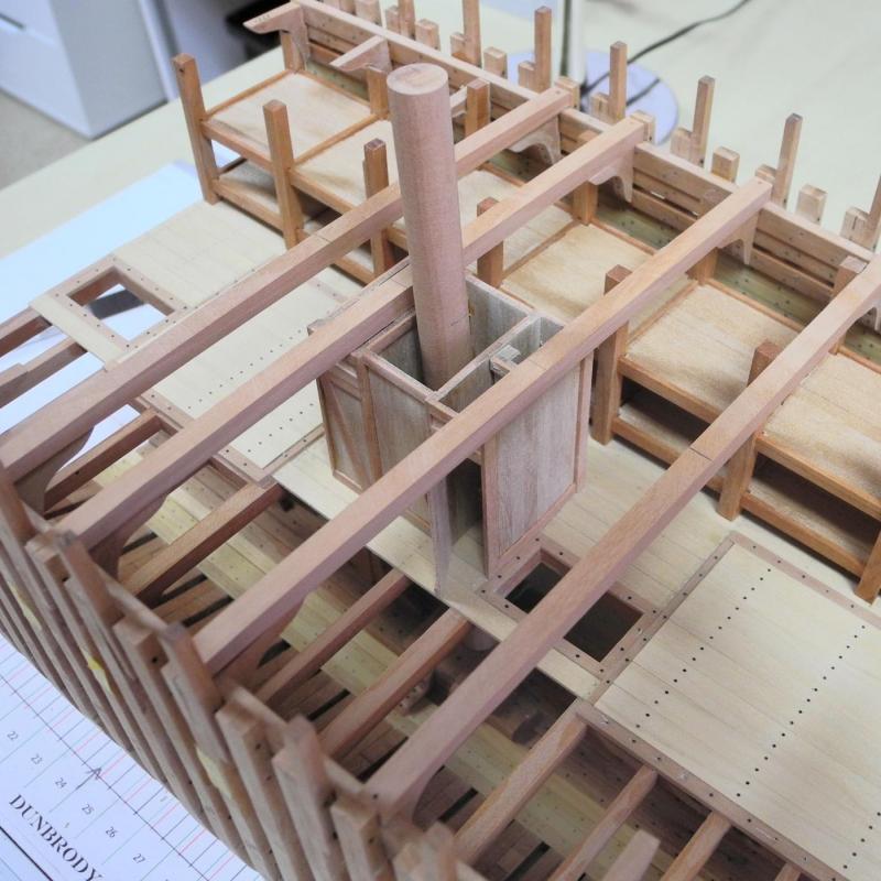
Part 40 – Main Deck Beams A lot of progress on Dunbrody today. I had previously made the deck beams for the main deck, and spent today installing the primary deck beams. This included epoxying the Accommodation Deck furniture in place. Work started with securing the sleeping platforms, the mast stub, and the bucket lavatories. Then the mast partners for the main deck, with the associated beams were installed. After that, the beams for the main hold forward of the main mast were installed. The forward safety railing was then glued in place. There are stanchions or pillars that support the main hatch – these were installed next. A molding was added to the pillars that are in the planked part of the deck. Once the Main Hold was framed out I was able to fix the forward table and benches in place. Then the forward-most beam was installed and a pillar was placed under the beam. Turning to the aft section, the table, benches, and safety railings were installed, followed by the framing for the aft hold and companionway. So now Dunbrody is ready for the lodging knees and the secondary beams for the main deck. I expect this work will take several days to complete. Thanks everyone!


- 649 replies
-
- 28
-
-
- dunbrody
- famine ship
- (and 2 more)
-
Thanks Brian. That's one of the things I really enjoy about the hobby - the exercise for the old grey matter. Thanks Albert!
- 649 replies
-
- 3
-
-
- dunbrody
- famine ship
- (and 2 more)
-
Thanks Alan. These jigs save a lot of alignment problems. I think I'd try to make them even if I didn't have the milling machine - it just makes it easier to make them.
- 649 replies
-
- 6
-
-
- dunbrody
- famine ship
- (and 2 more)
-
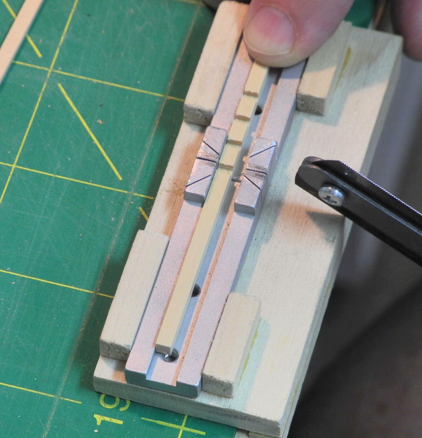
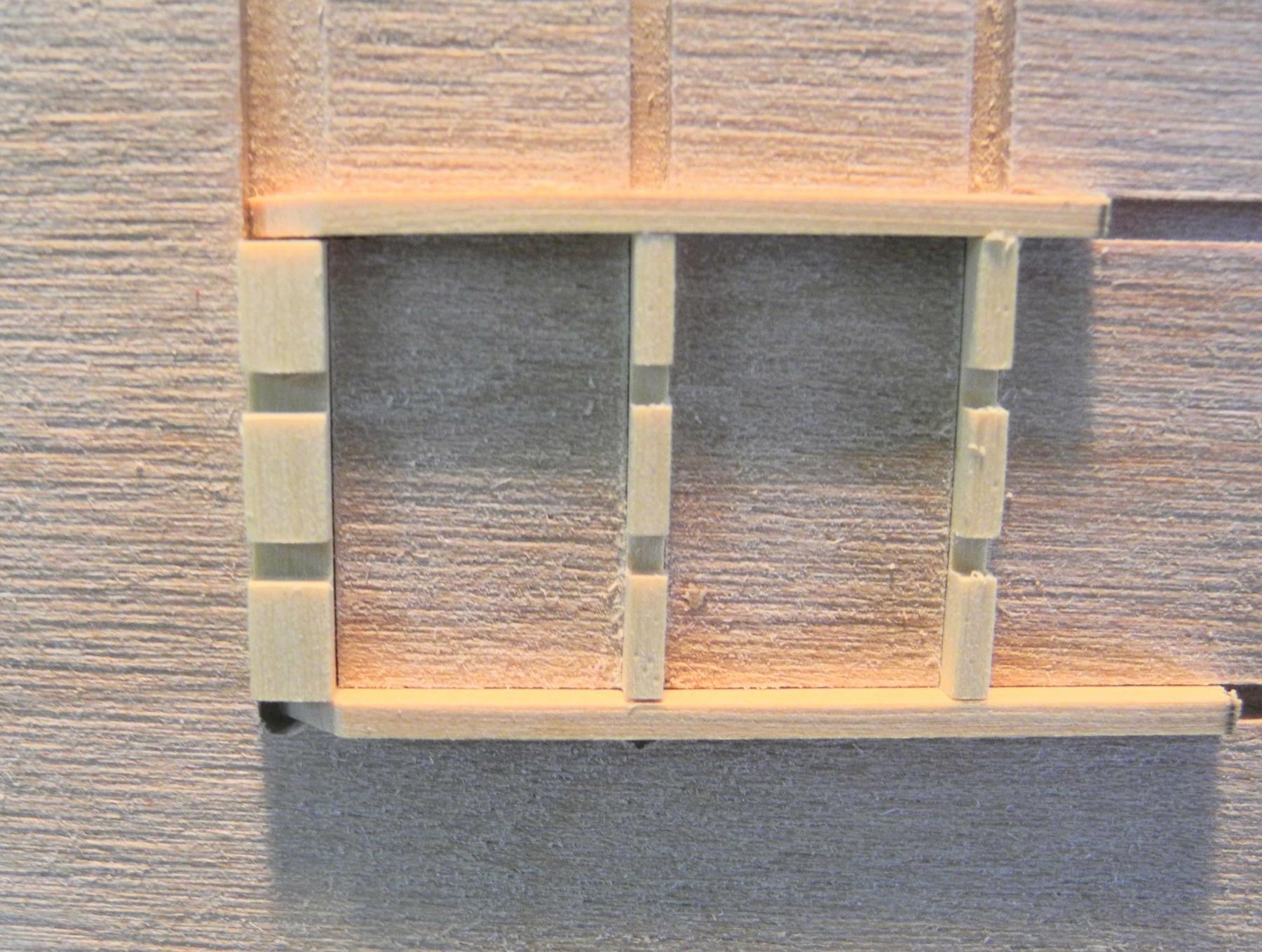
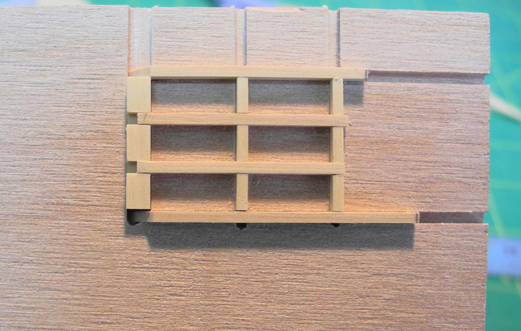
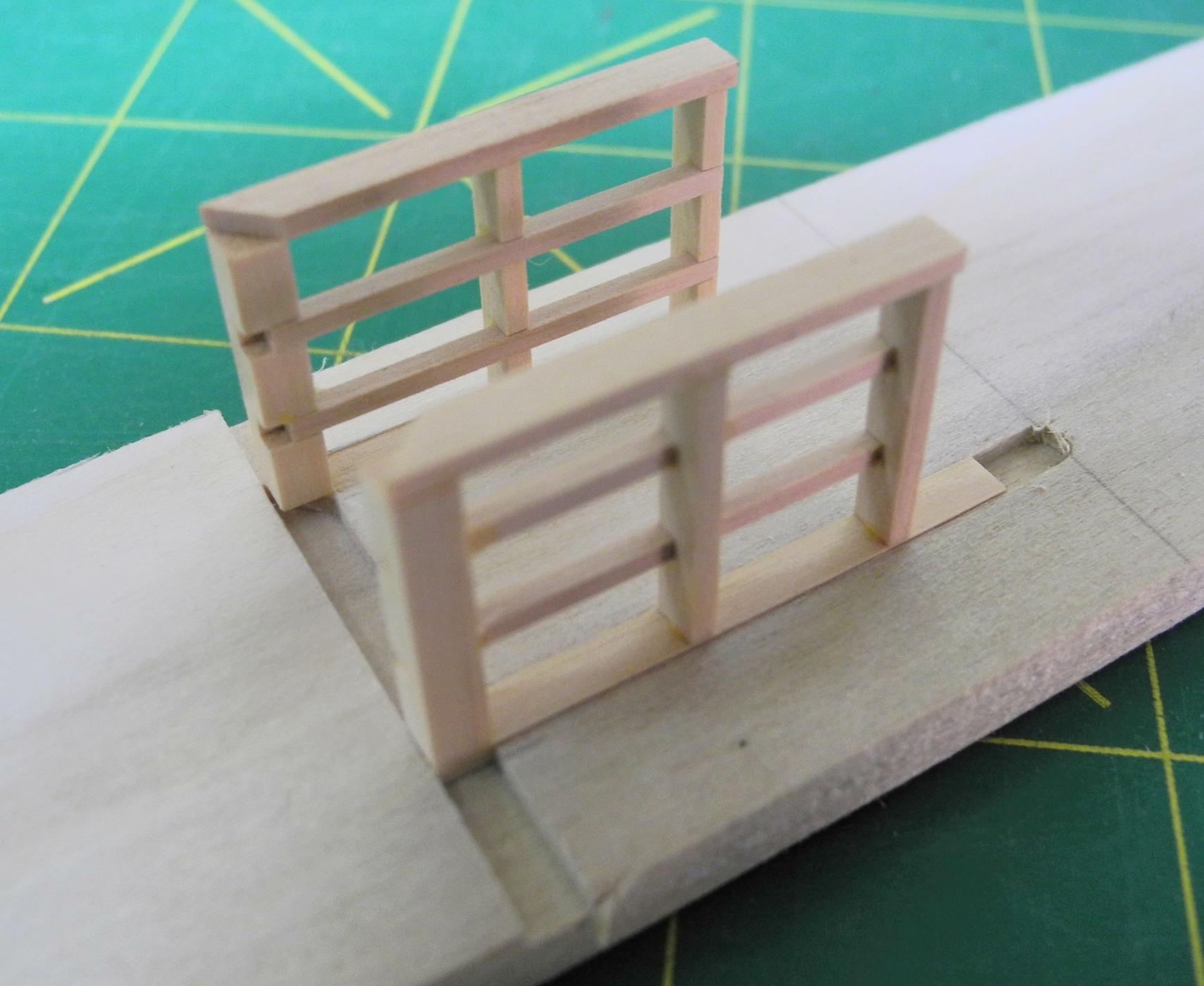
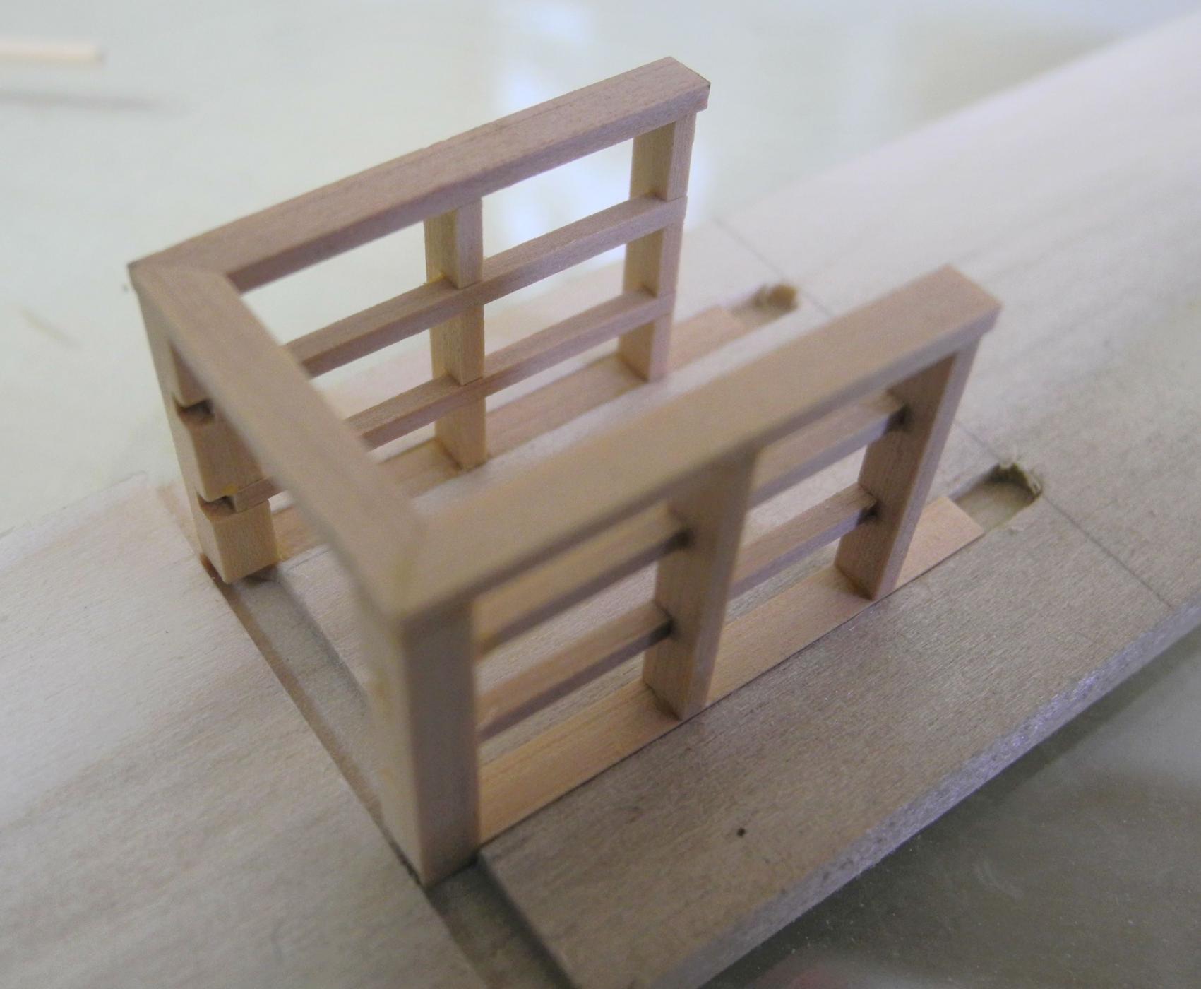
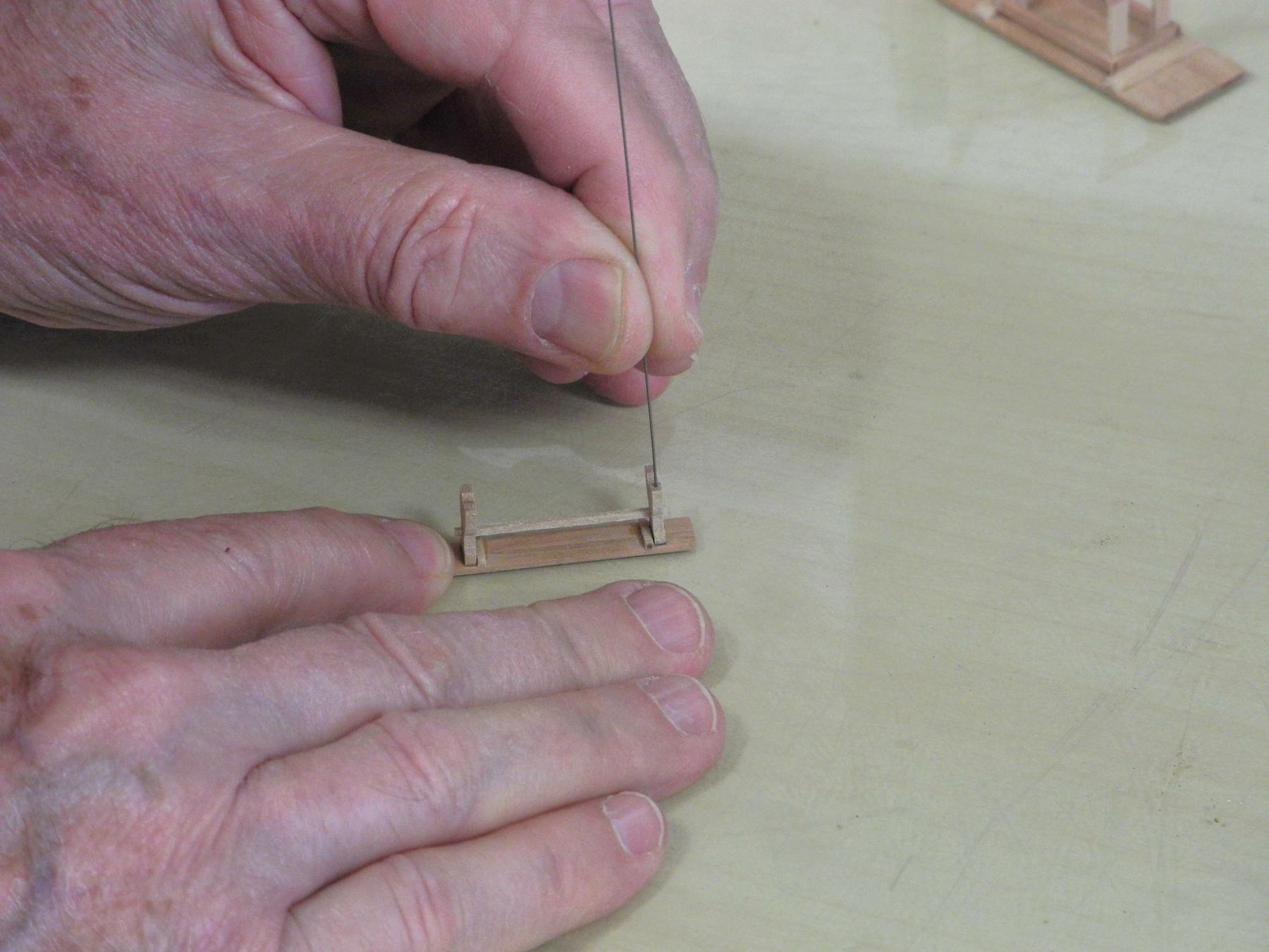
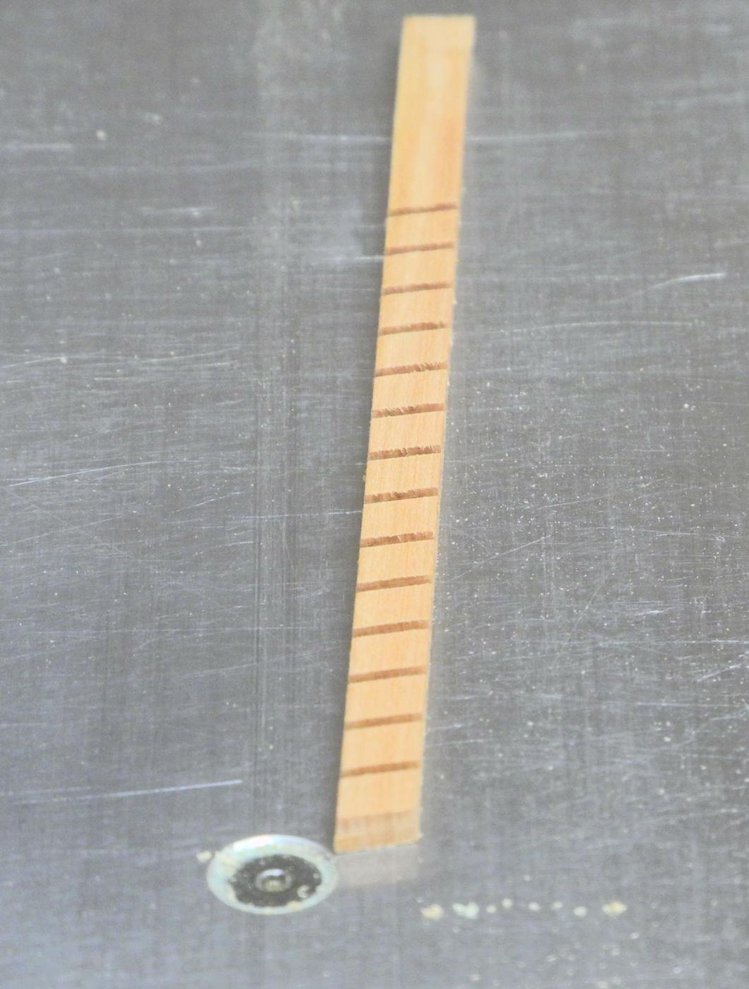
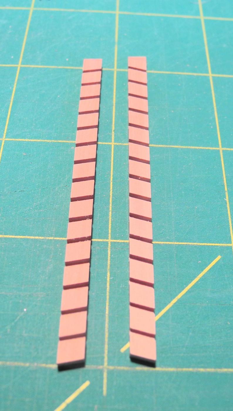
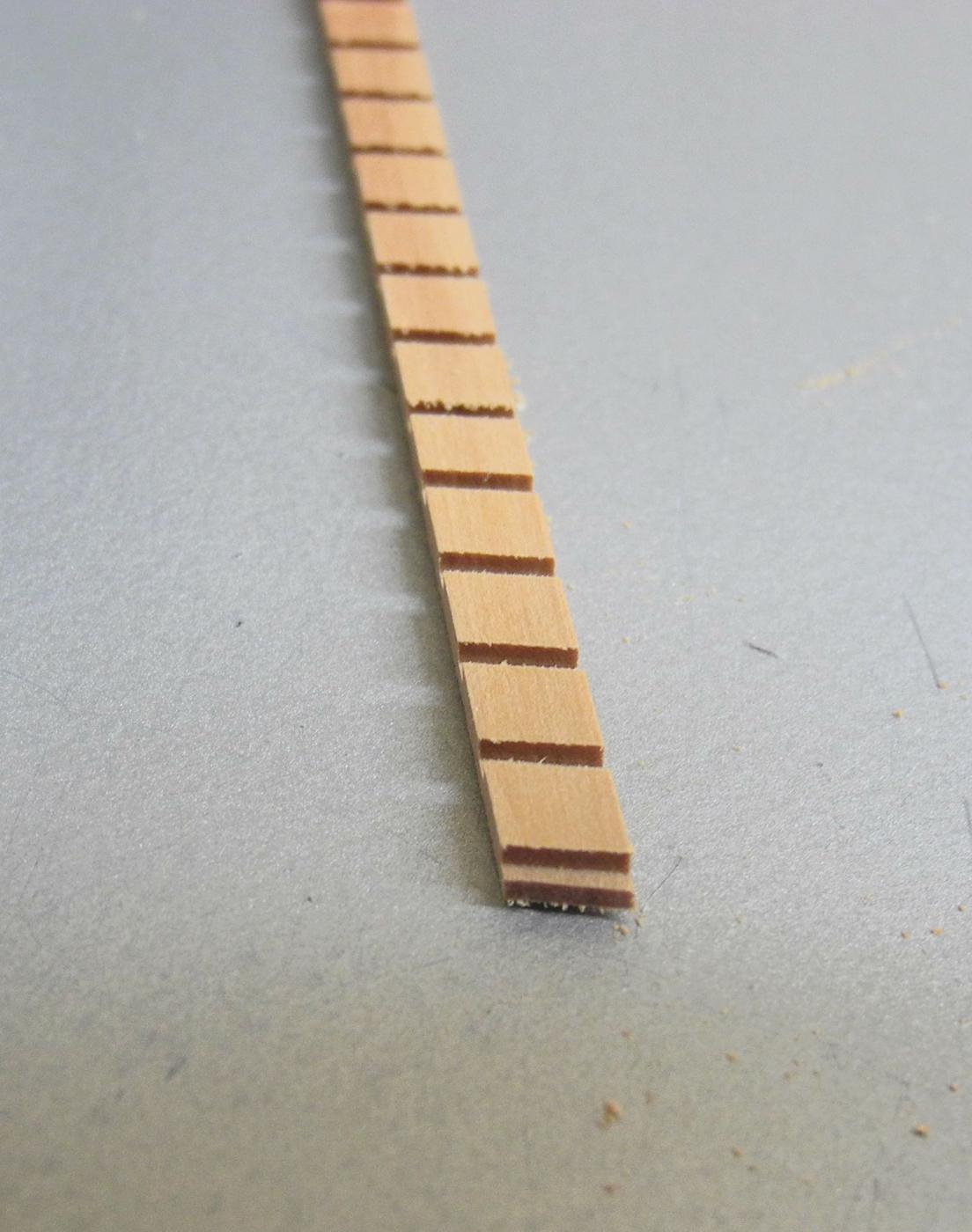
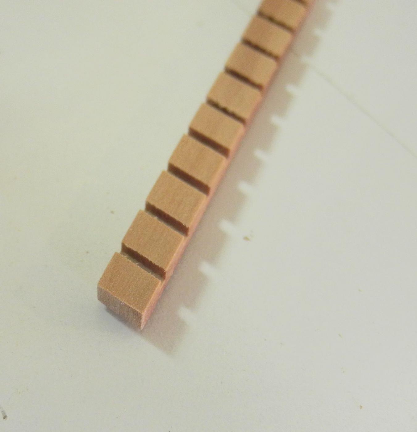
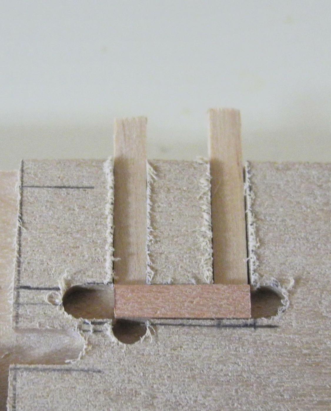
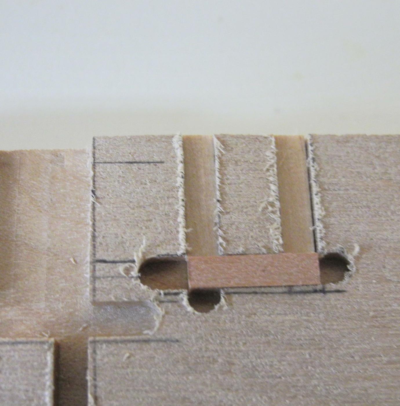
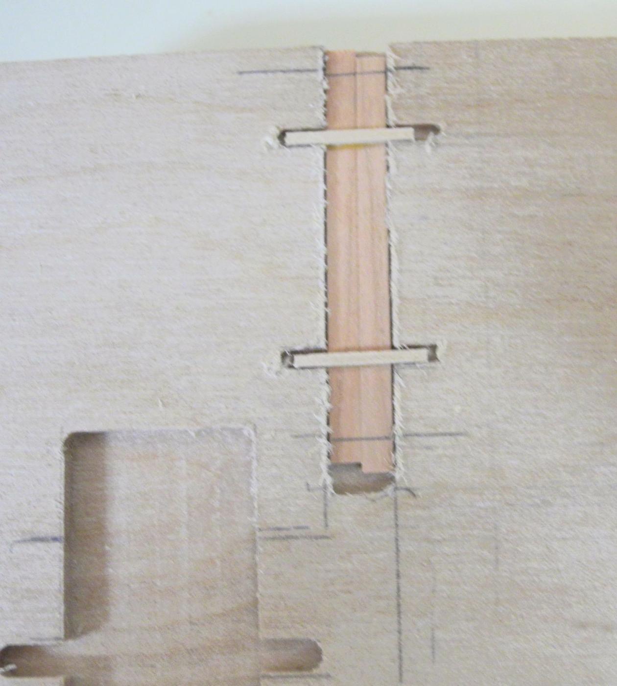
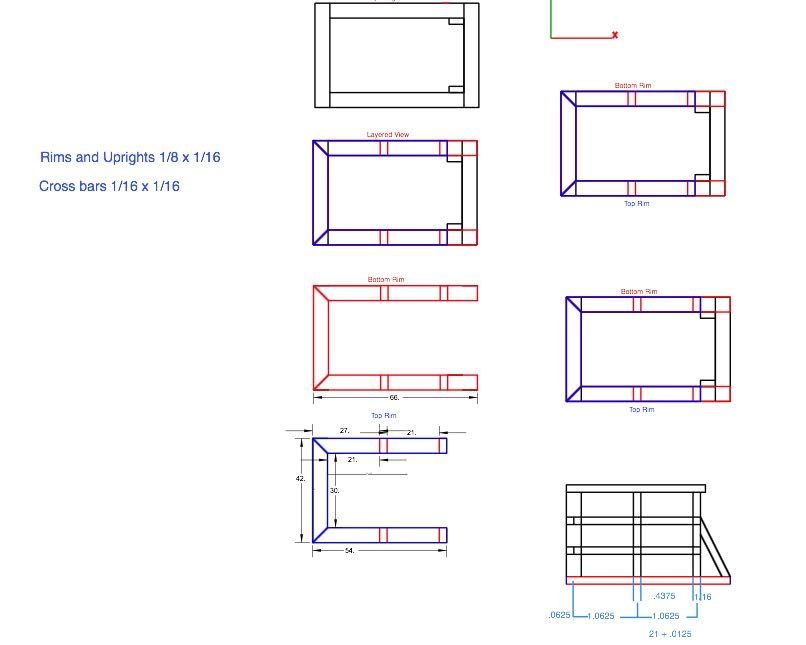
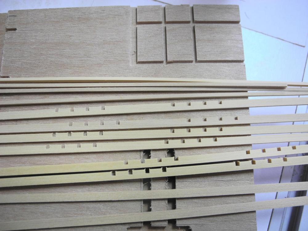
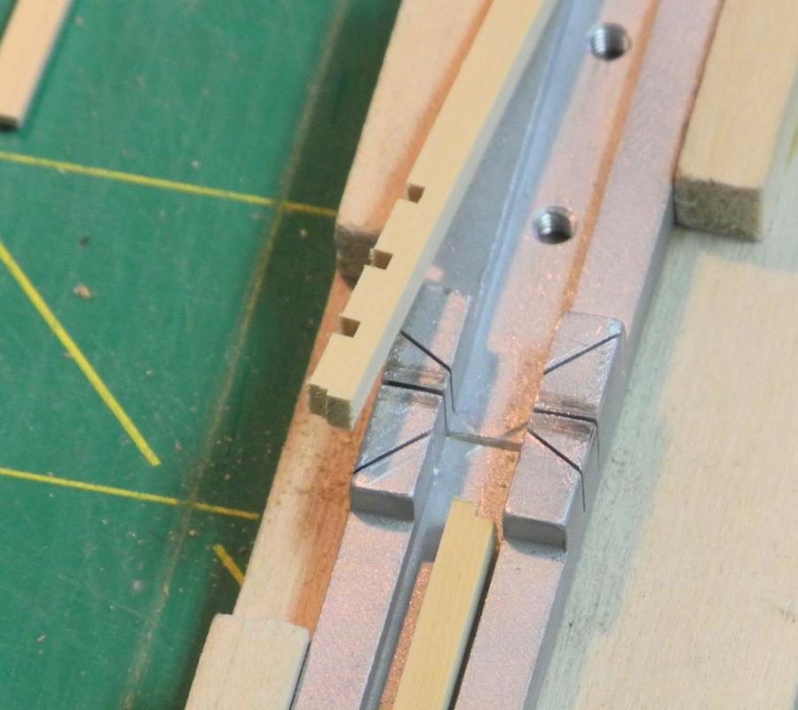
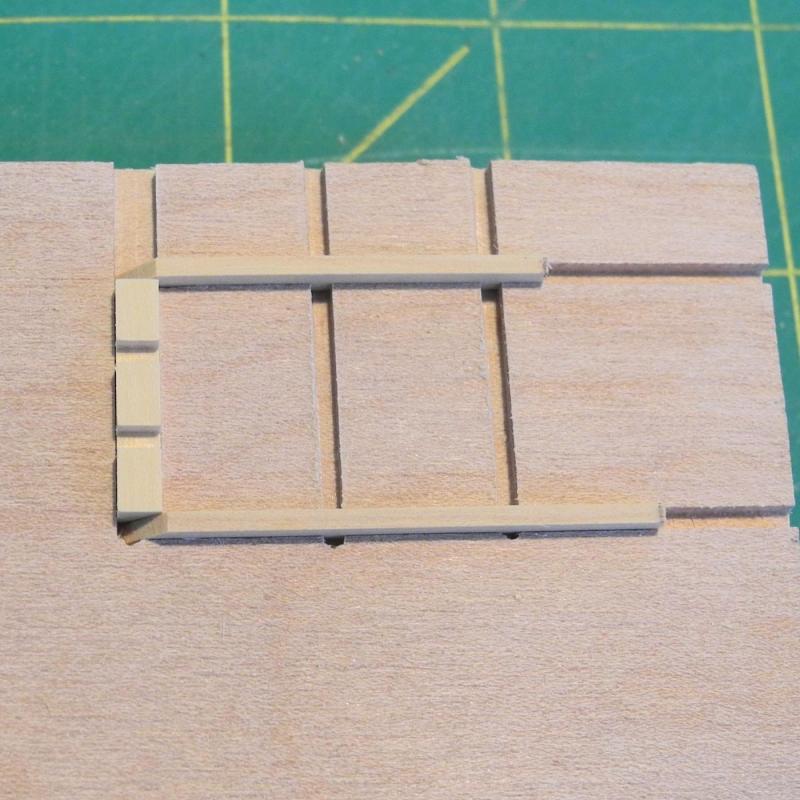
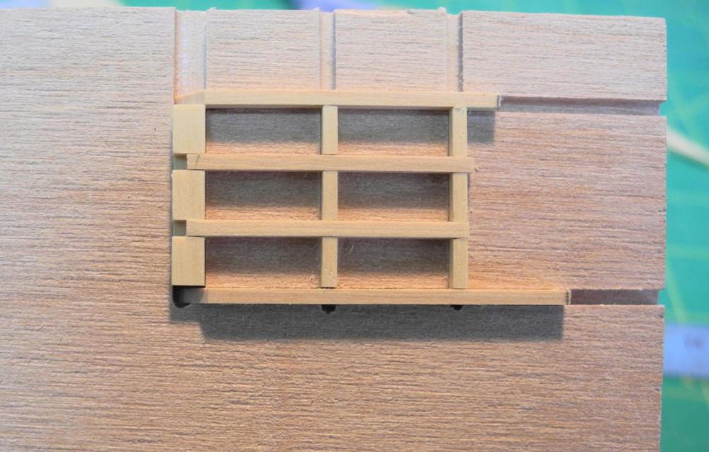
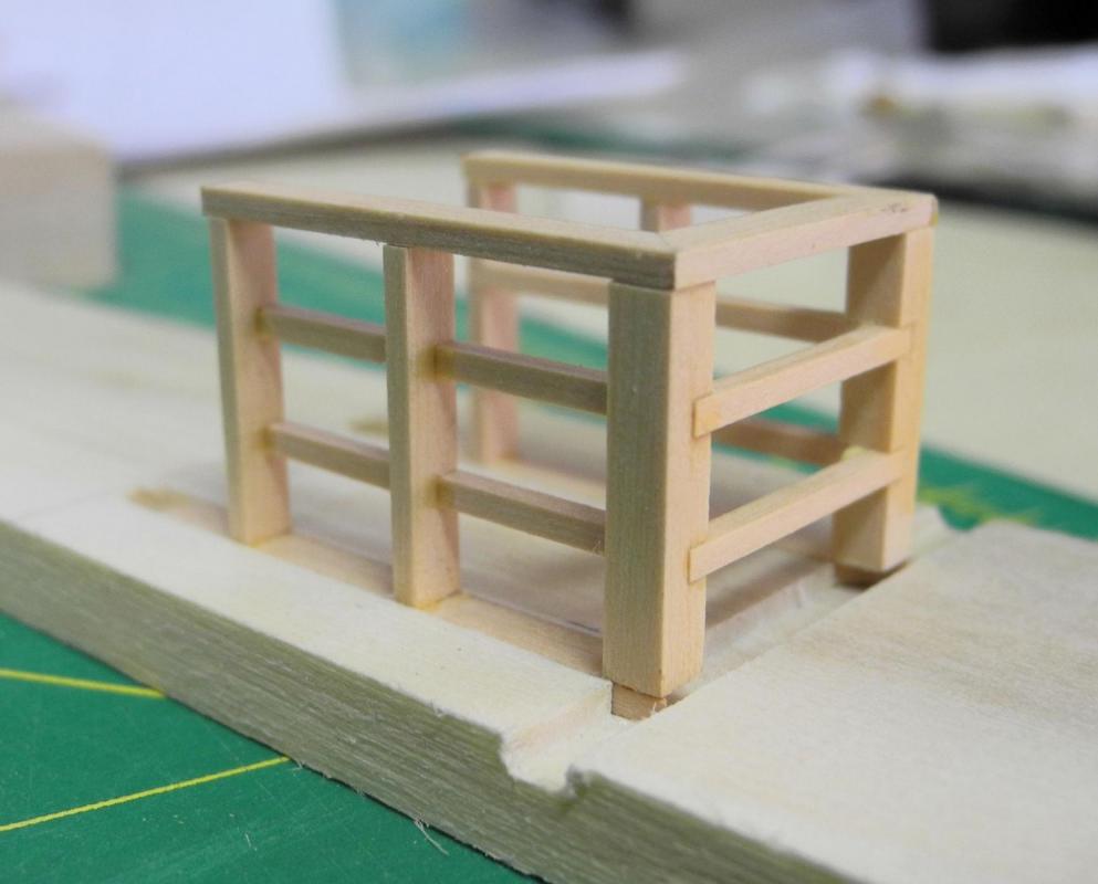
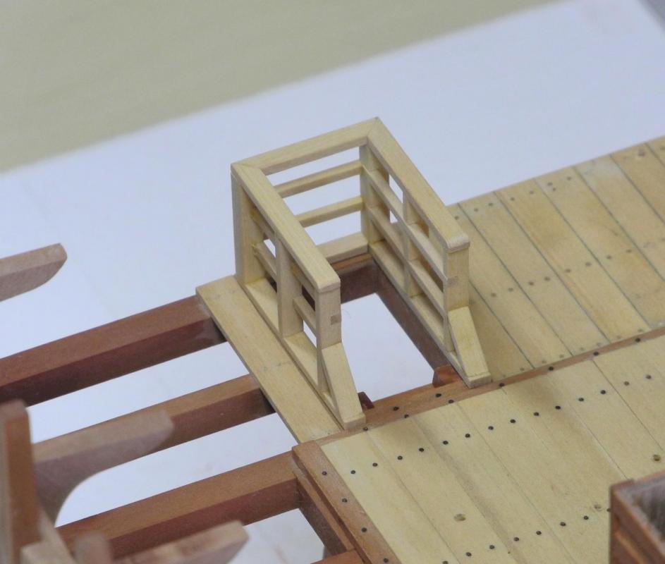
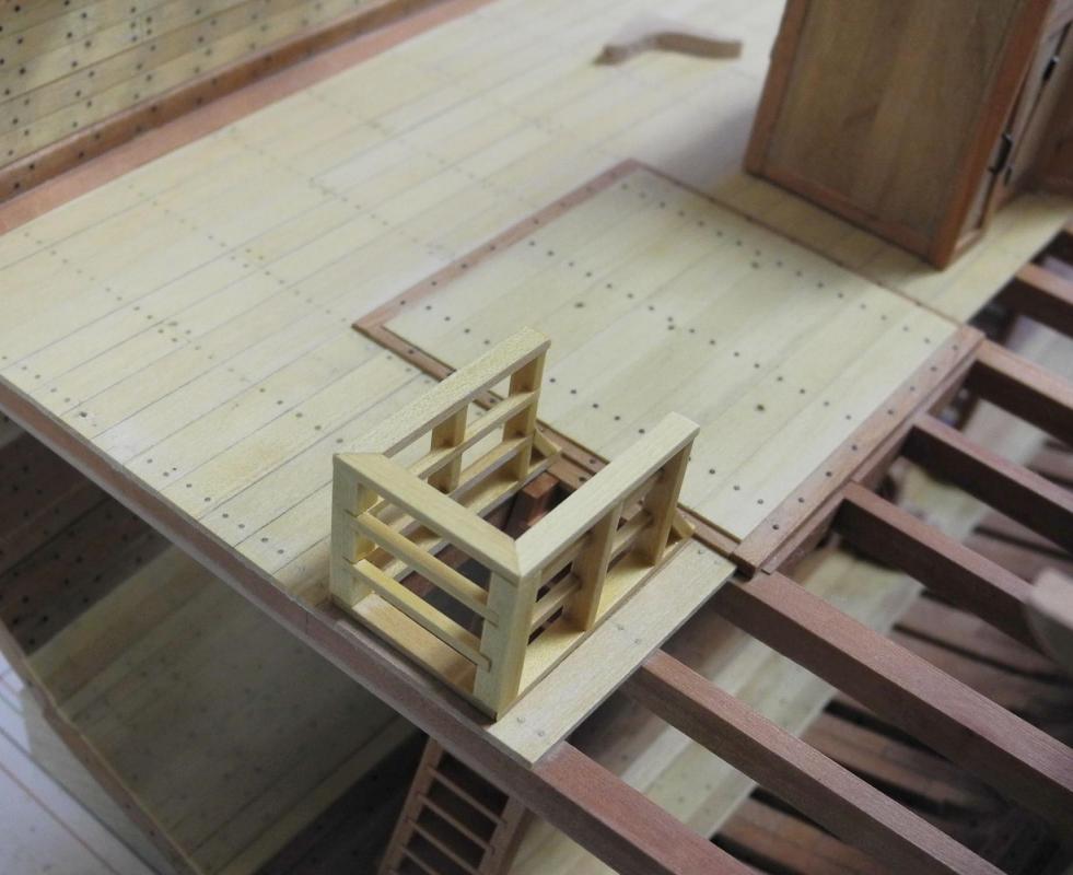
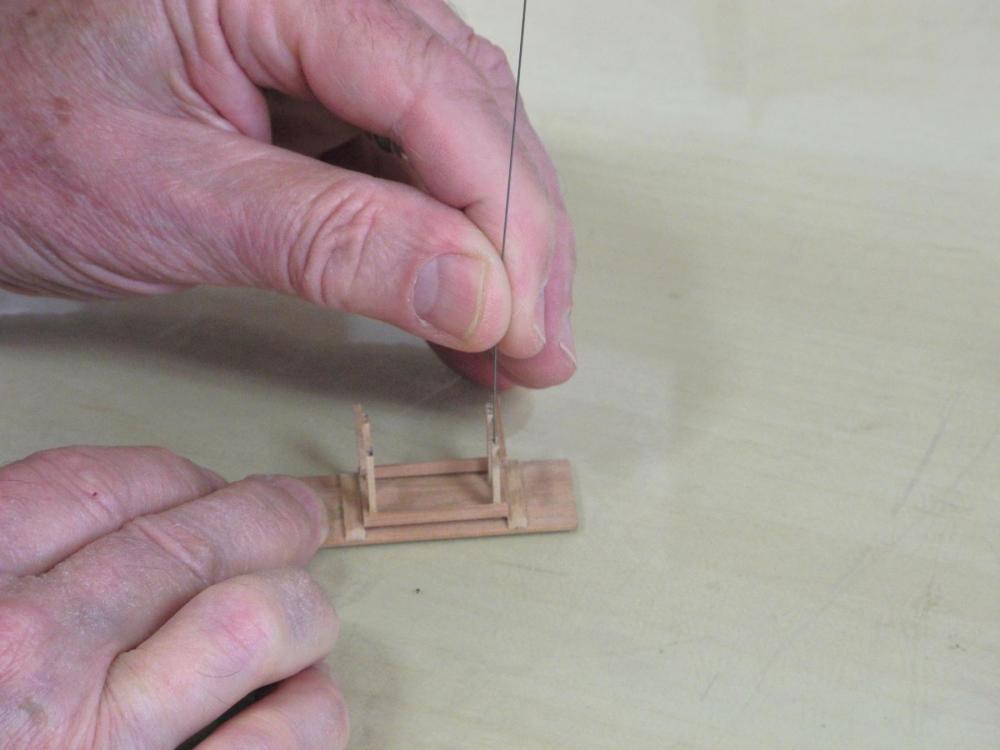
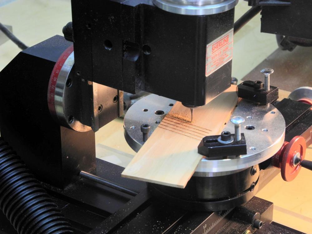
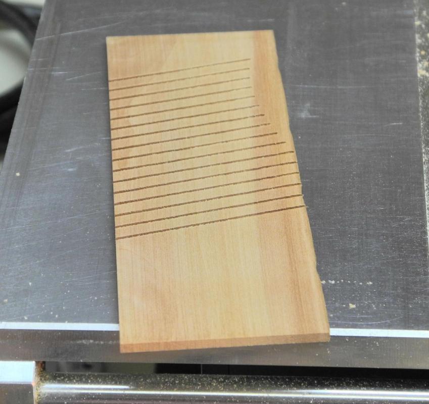
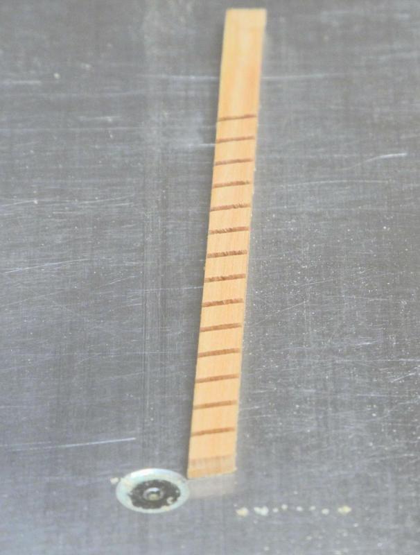
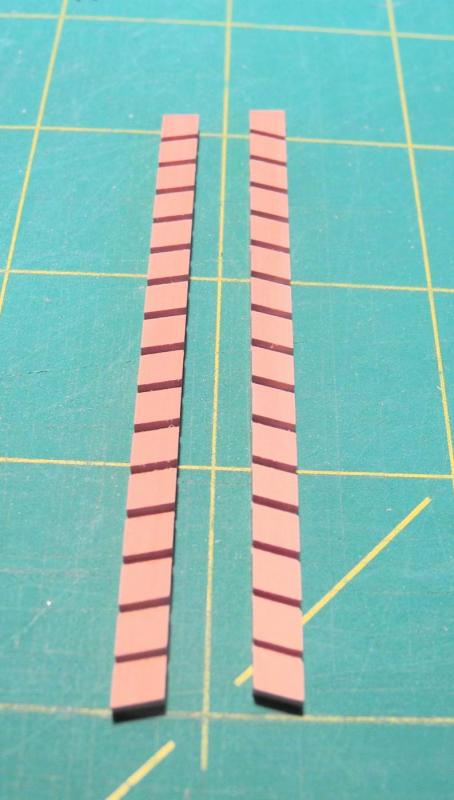
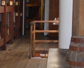
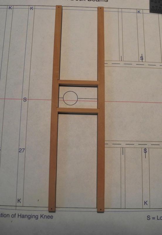
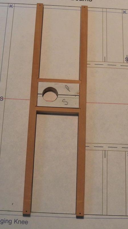
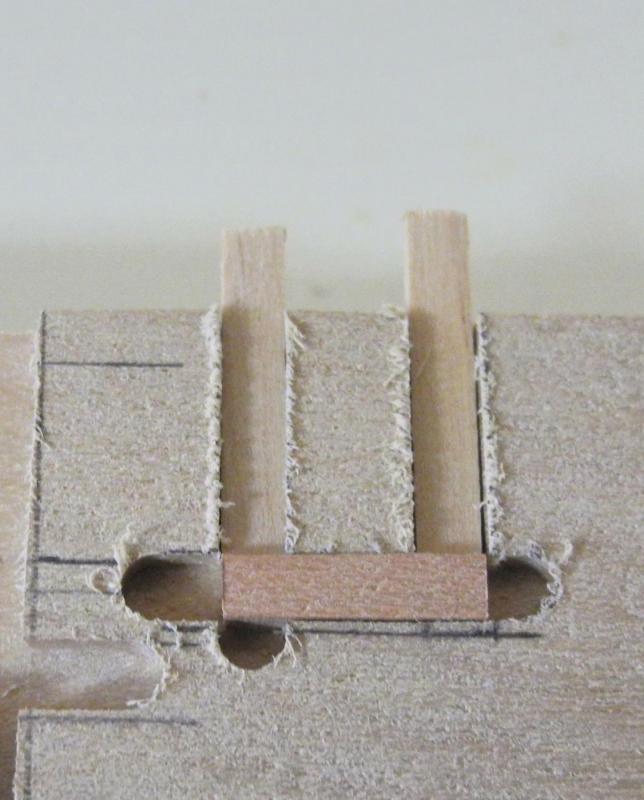
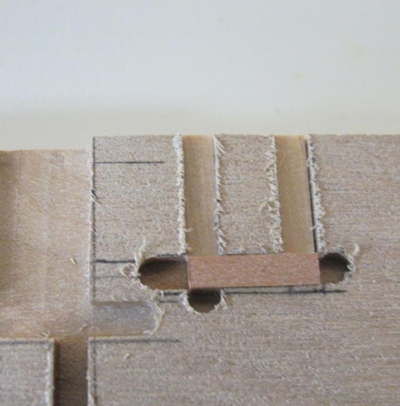
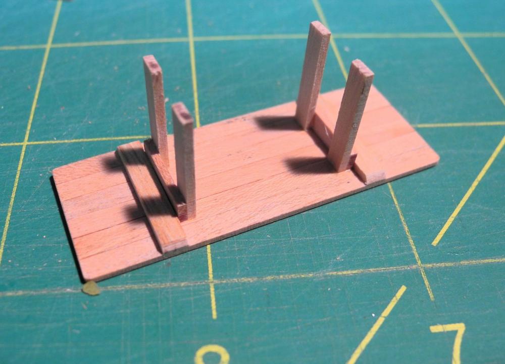
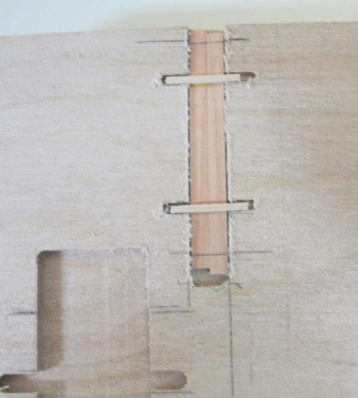
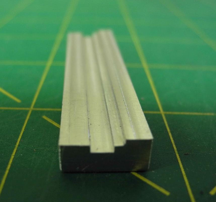
Part 39 – Safety Railings As shown in the last post, the replica ship has safety railings around the companionways for access to the hold. As discussed in previous posts these railings may only be part of the modern replica ship, but my feeling is that the crowded Accommodation Deck would have made the companionway openings quite dangerous, and the railings may have been at least temporary installations during the emigrants’ voyage. So I decided to build them. The railings were sized to fit over the framing on the companionways, and CAD plans were developed The railings were made from 3 x 6’s (1/16 x 1/8). The upright members would be notched for the horizontal railings, so these notches were cut into a 1/8 thick billet using the milling machine. Timbers were then parted off and shaped to the final dimensions in the thickness sander. A jig for assembling the pieces was needed to keep everything properly aligned. The jig was made on the milling machine and can be seen in the above photo. The individual pieces of stock had 5 grooves cut in them. The first and last grooves were for cutting out the part. The top rail and the bottom rim were mitered and placed into the jig. Then the individual pieces were added to the jig. Then the horizontal braces were glued into the notches in the vertical pieces. When dry, these side pieces were removed from the jig and the top rail and bottom rim were glued to the sides. These sides were then placed in a separate jig that was designed to hold the sides square to each other. A mitered top cross-piece was glued in place, followed by the horizontal braces for the front of the assembly. The assembly was then removed from the jig and the bottom mitered cross-piece was glued in place. Small ‘bumpers’ were added to the bottom rim. The following photos show the completed railings in place. All of the individual components for the Accommodation Deck are now completed, and installation of the Main Deck beams can begin. Thanks everyone, and enjoy the weekend!


- 649 replies
-
- 27
-
-
- dunbrody
- famine ship
- (and 2 more)
-
Hi Bob. That's a good thought, and I debated whether to build the safety railings. Thinking of the deck being crowded with people and the tables and benches being only a few feet from the companionways down to the hold, I thought it would be better to have them. Besides, it's another little finicky detail I can stress over.
- 649 replies
-
- 5
-
-
- dunbrody
- famine ship
- (and 2 more)
-
Hi Patrick. It would be nice to think so, but there's still the main deck to build, including hatchways, companionways, railings, etc, etc. Not to mention exterior planking on the port side, and I still need to design and build the display stand (hopefully a simulated launching ways).
- 649 replies
-
- 4
-
-
- dunbrody
- famine ship
- (and 2 more)
-
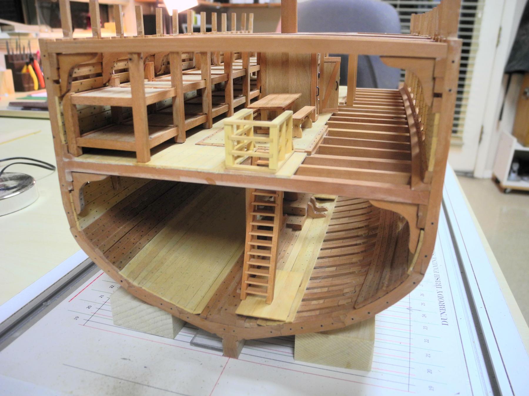
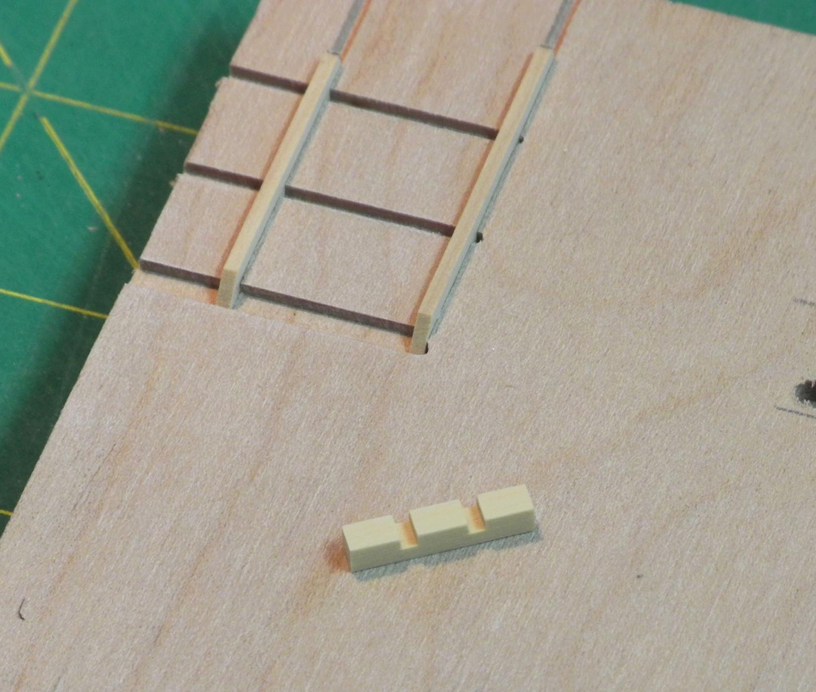
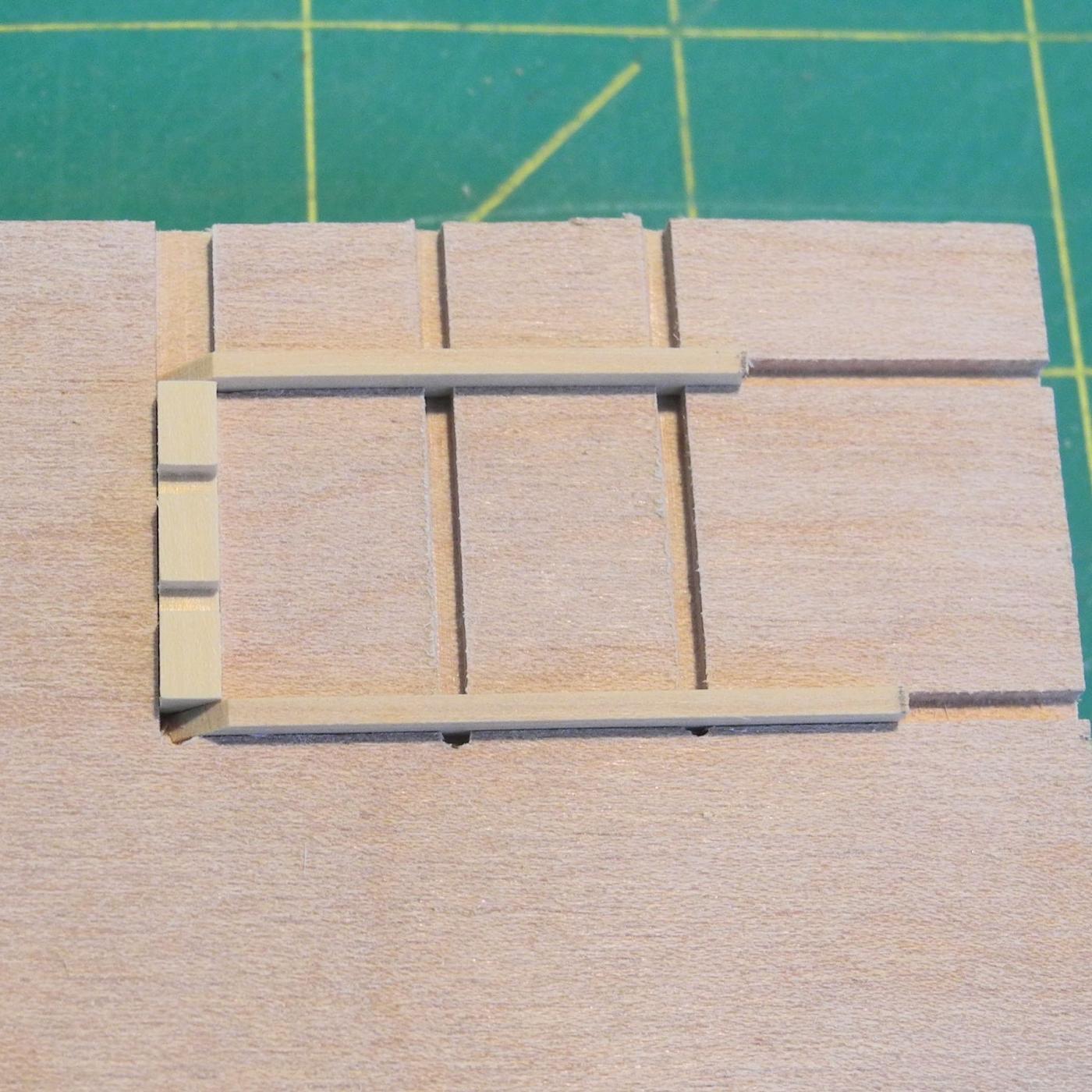
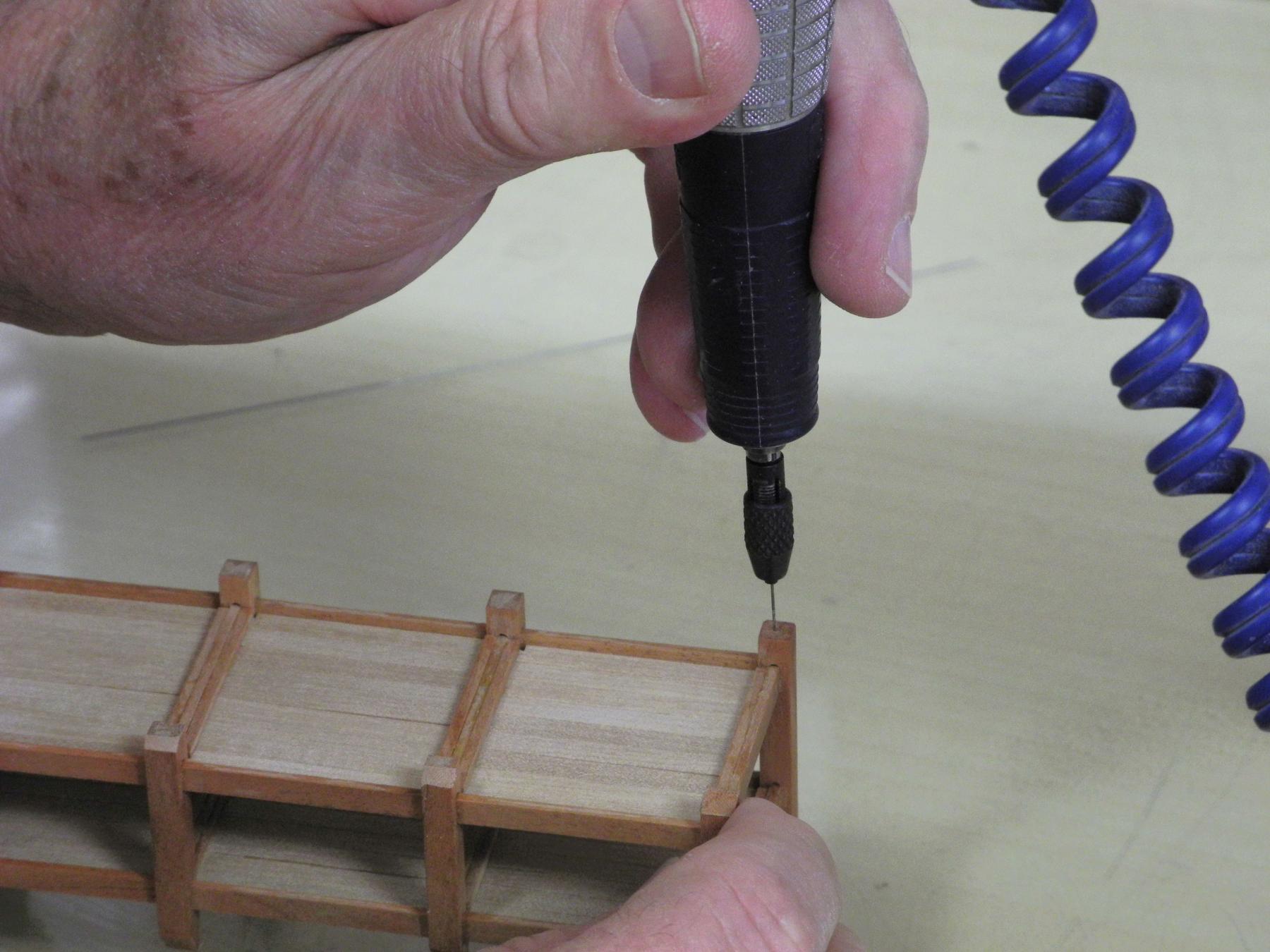
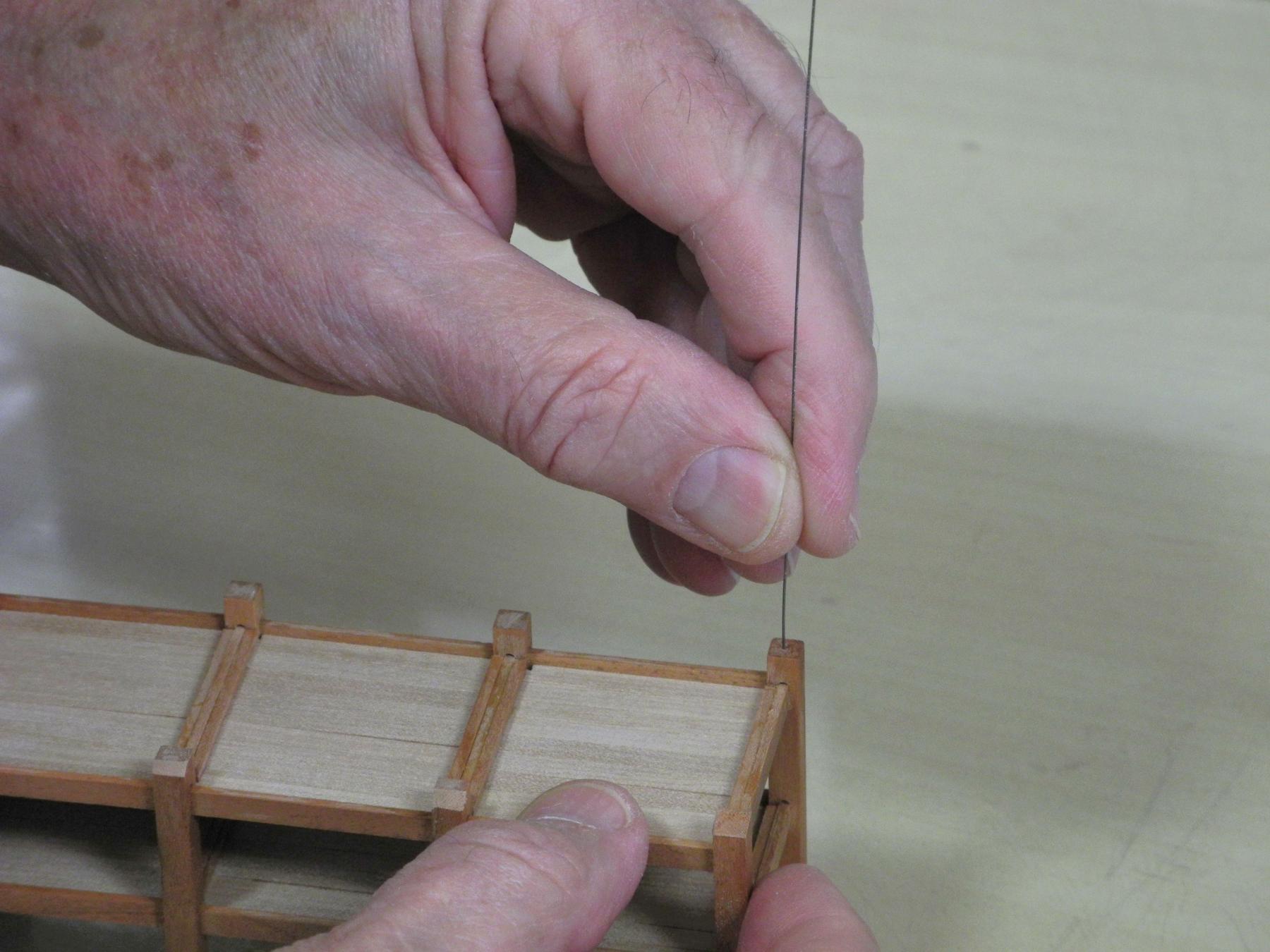
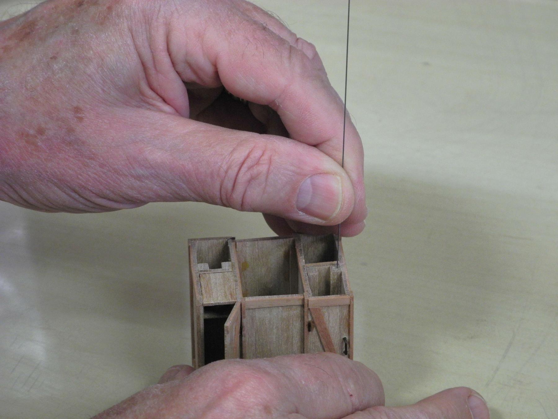
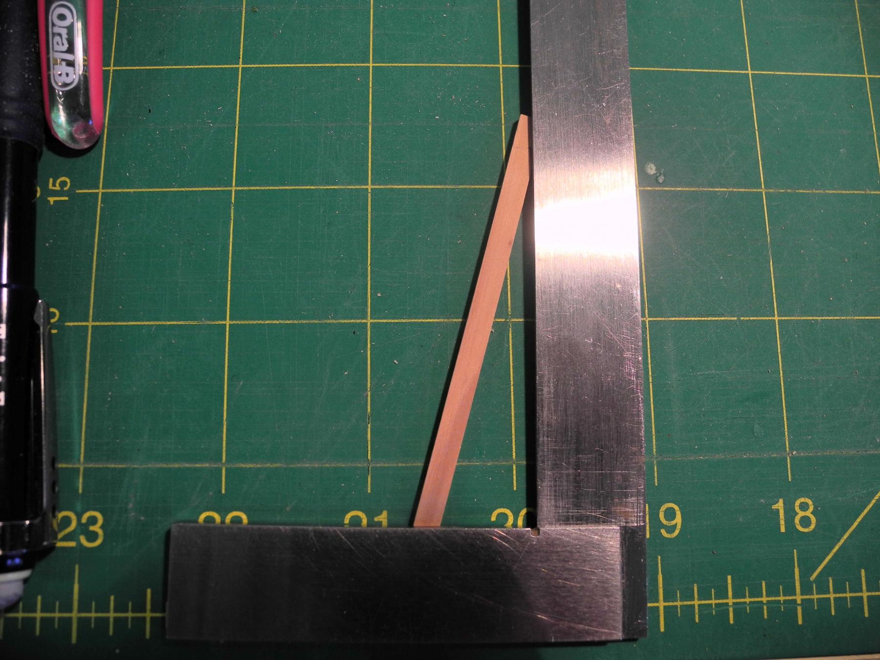
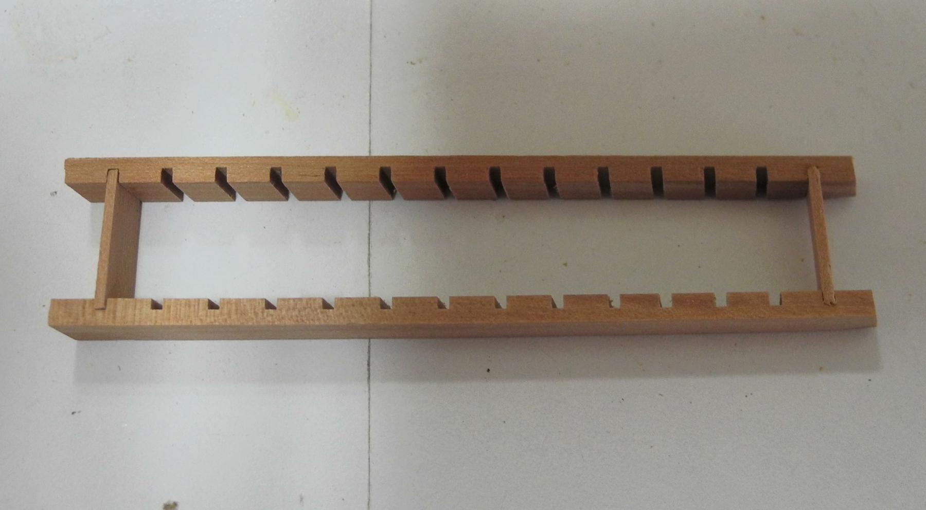
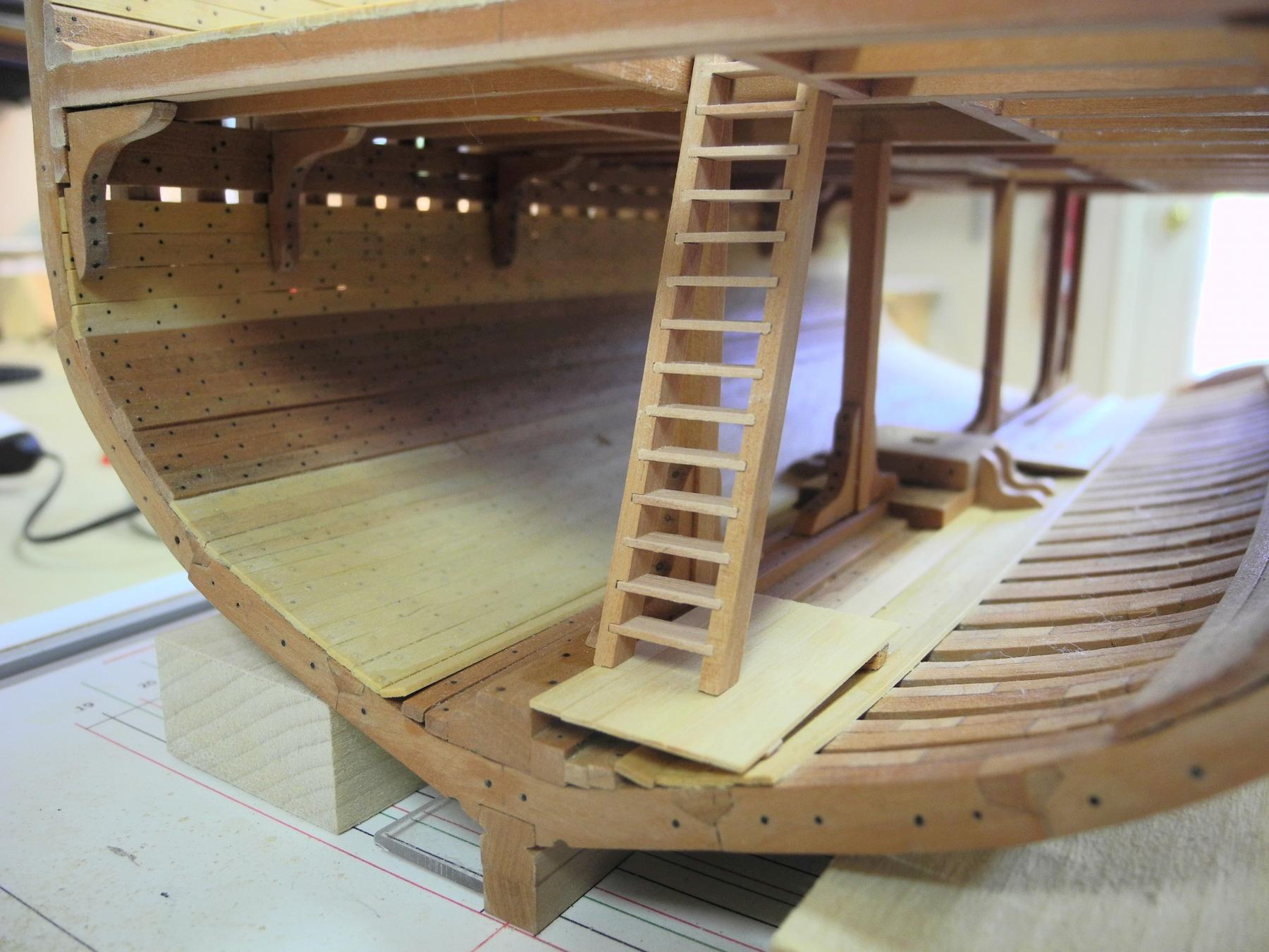
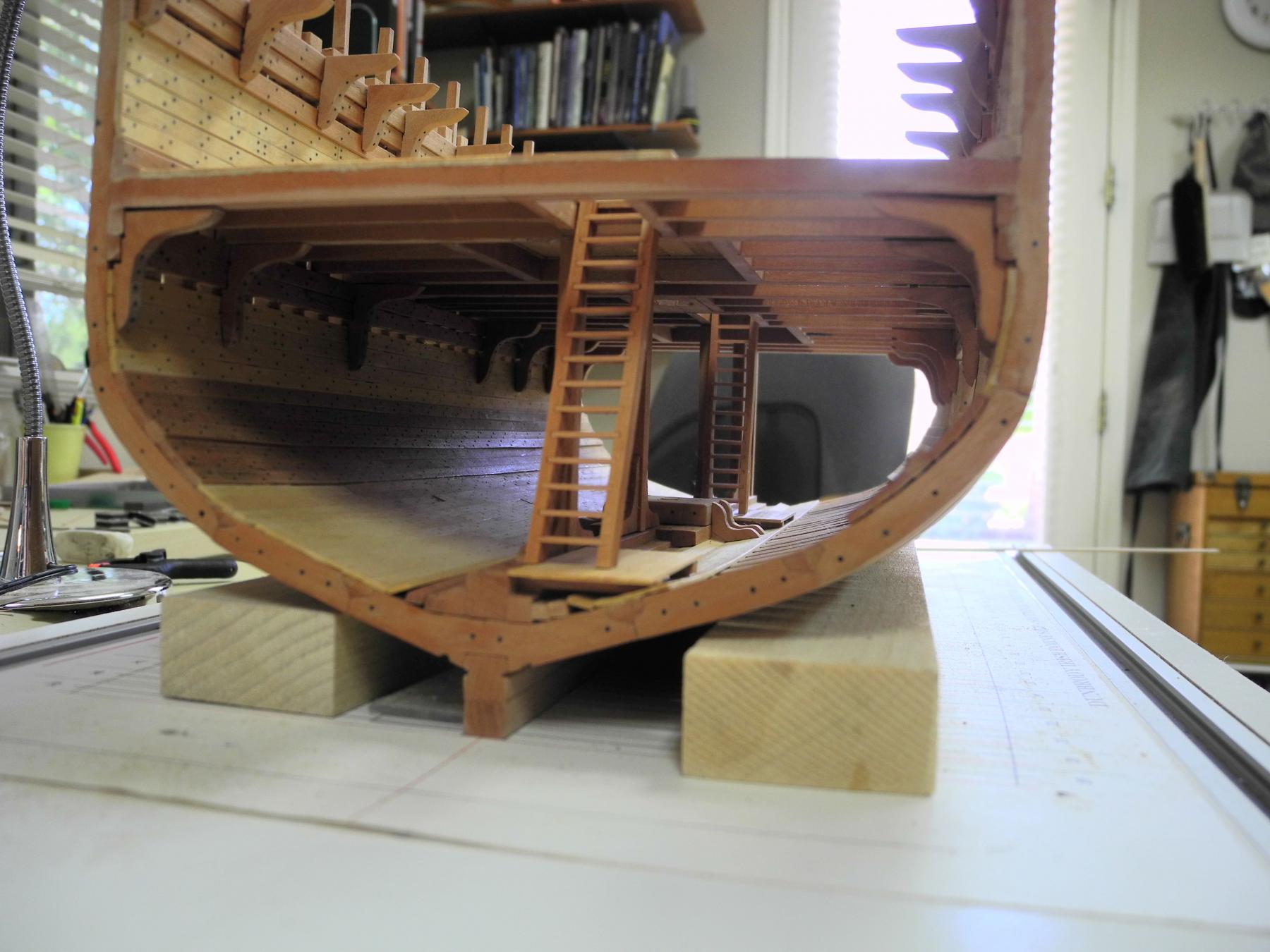
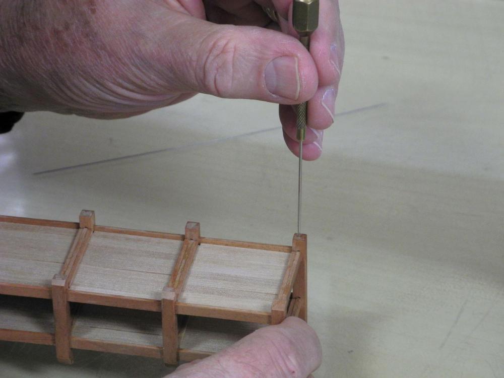
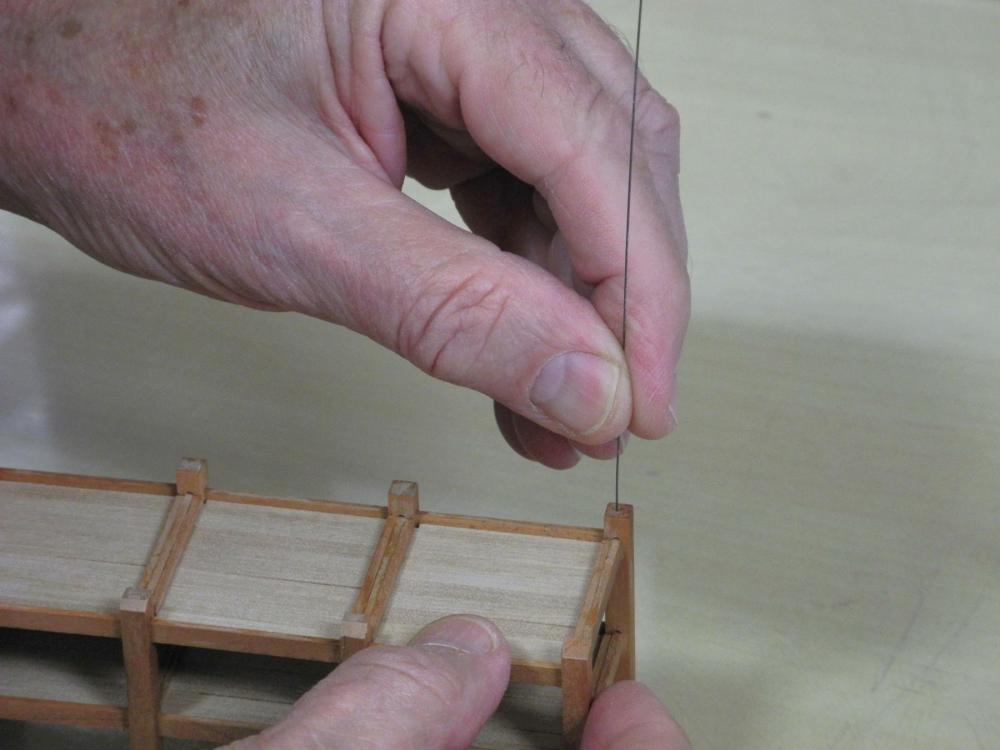
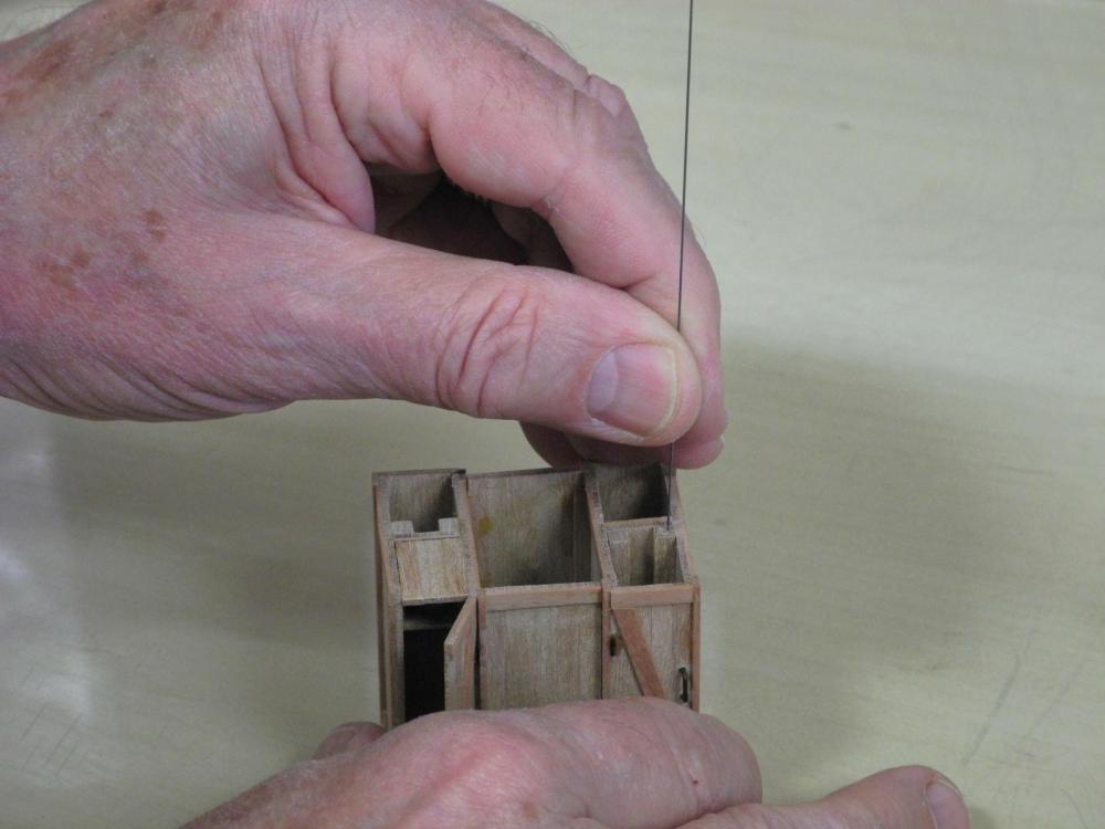
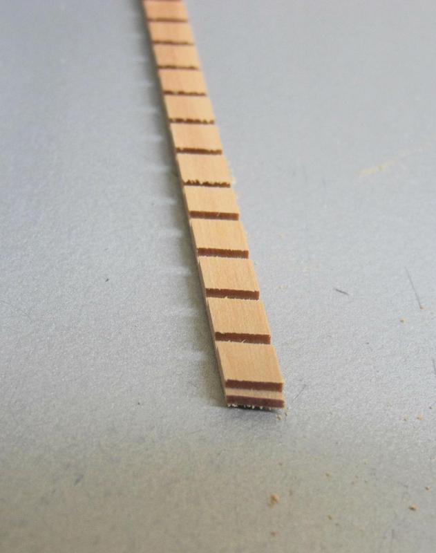
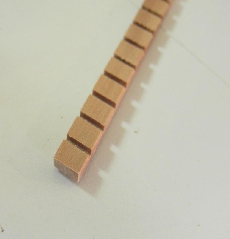
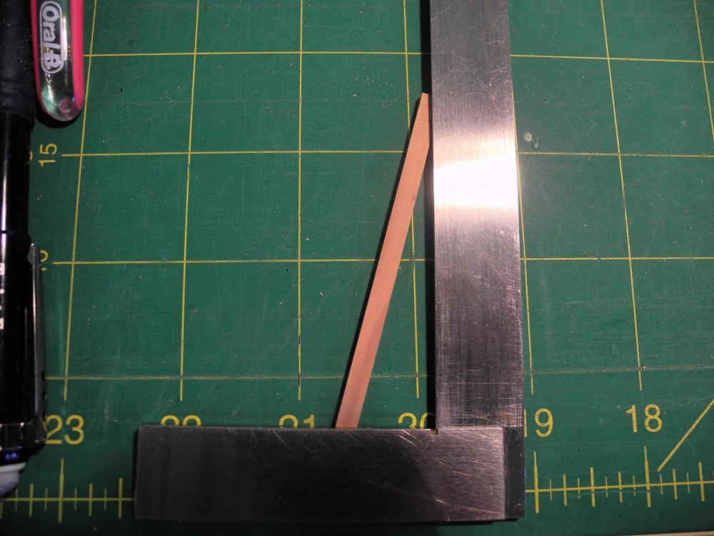
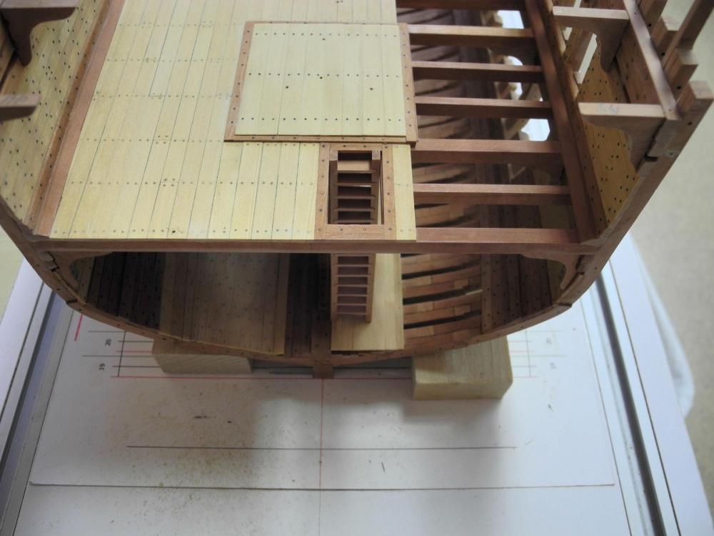
Part 38 – Finishing the Accommodation Deck, Ladders The outside of the frames needed a lot of sanding to clean up excess glue and for fairing the frames - especially on the port side, which will be fully planked. It made sense to do this sanding before any more details were installed, since that would make it harder to clean out the sanding dust. And since I had Dunbrody off the building board for cutting the view ports, I decided this was the best time to get this sanding out of the way. I spent about a day on the sanding, but didn’t take any pictures. Next up was applying a finish to the Accommodation Deck and the furniture that was just built – the lavatories, tables, and chairs. I used wipe-on poly for the finish. Again – no photos, since there’s really nothing to show on any of the work that was done. The furniture for the Accommodation Deck – sleeping platforms, lavatories, tables, and benches – will need to be pinned to the deck for security. Very thin piano wire - .014 thickness – was used since some of the items were extremely small. The piano wire stays straight even though it’s very thin – this made it a good material for pins. The pinning work started by making starter holes with a very fine awl. (This awl is actually a fly-tying bodkin, but serves very well when a very small awl is needed) A #78 drill was used to make the holes. The rotary tool with a variable-speed foot pedal allowed very controlled and accurate drilling in these tiny objects. The pins were glued into the holes with epoxy. The following photo shows all of the furniture temporarily pinned to the deck. The two ladders to the Hold were the next items to be built. Unfortunately, planning the installation of the ladders pointed out a serious problem. Those members who participated in my topic on Planning the Dunbrody Sectional Model may recall that there were some questions about an Orlop Deck in the ship. The construction plans showed an Orlop Deck, but the details were very sketchy. The reference material I’ve been using for Dunbrody did not indicate any orlop decks in use for the freighters and packets built at the same time Dunbrody was built. I decided NOT to include the orlop deck. Not including an orlop deck was a mistake, since without an orlop deck Dunbrody’s hold ladders would sit right on the limber strake. To work around this, small platforms were installed for the ladders to land on. The stringers for Dunbrody’s hold ladders are 9 inches wide and 3 inches thick. The treads are 2 inches thick, and are set 9 inches apart. The ladders are set at an angle of 14 degrees. The milling machine was used to cut the slots for the stringers. Since the actual size of the treads is .0417 inches, a miniature cutter that measured .042 inch diameter was used to cut the slots. The workpiece was held in a circular tooling plate on the rotary table. The table was set at 14 degrees and the slots were cut. A workpiece that provided enough room for several stringers was used. After the milling, a stringer was parted off. The same process was used for the stringer for the opposite side of the ladder. The bottom slot was used as the base of the ladder. First the stringer was cut at this slot, removing any excess material. The base of the ladder was then sanded to the top of the slot on the disk sander. A square was used to mark off the top part of the stringer that will rest against the companionway opening. The top and bottom rungs were glued in place first. Then it was a simple matter of sliding the rest of the treads into the grooves. The top of the ladder is flush with the deck, so that the first tread is the same distance from the deck as between treads. The first ladder was completed and tested in place. When both ladders were built, they were then sanded and a poly finish was applied. Then the ladders were installed in the hold. A safety railing is needed around each of these ladders, as shown in these photos of the replica Dunbrody. This will be the topic for the next post. Thanks everyone


- 649 replies
-
- 15
-
-
- dunbrody
- famine ship
- (and 2 more)
-
Nice work Patrick! The railings look very nice. Getting the spacing and the alignment correct at your scale must have been quite a challenge.
-
Thanks Bob. I'm spending lots of time in the shop - trying to get Dunbrody ready for the NRG Conference in San Diego, so I have a self-imposed deadline.
- 649 replies
-
- 4
-
-
- dunbrody
- famine ship
- (and 2 more)
-
Thanks Druxey. Yes, it was a nervous day in the shop, and I'm glad that step is done. I agree on the furniture - it must have been secured in place for the trip. But when you consider that the furniture was probably discarded at the end of the trip (or at least taken down and put in the hold) the fastenings were probably pretty basic. Thanks Brian. I've been thinking of scheduling our next meeting - I'll be sending out an email today or tomorrow. Good idea Mike - it probably would have helped.
- 649 replies
-
- 4
-
-
- dunbrody
- famine ship
- (and 2 more)
-
Thanks Greg! Thanks Mike. Thinking about it was the scariest part. There were a few little slips that nicked adjacent frames, but overall it went well. Hi Patrick - thanks. I started out as a computer programmer, so I guess in a way I was an engineer. Now, if I had your skills I'd put some plates and cups on those little tables!
- 649 replies
-
- 5
-
-
- dunbrody
- famine ship
- (and 2 more)
-
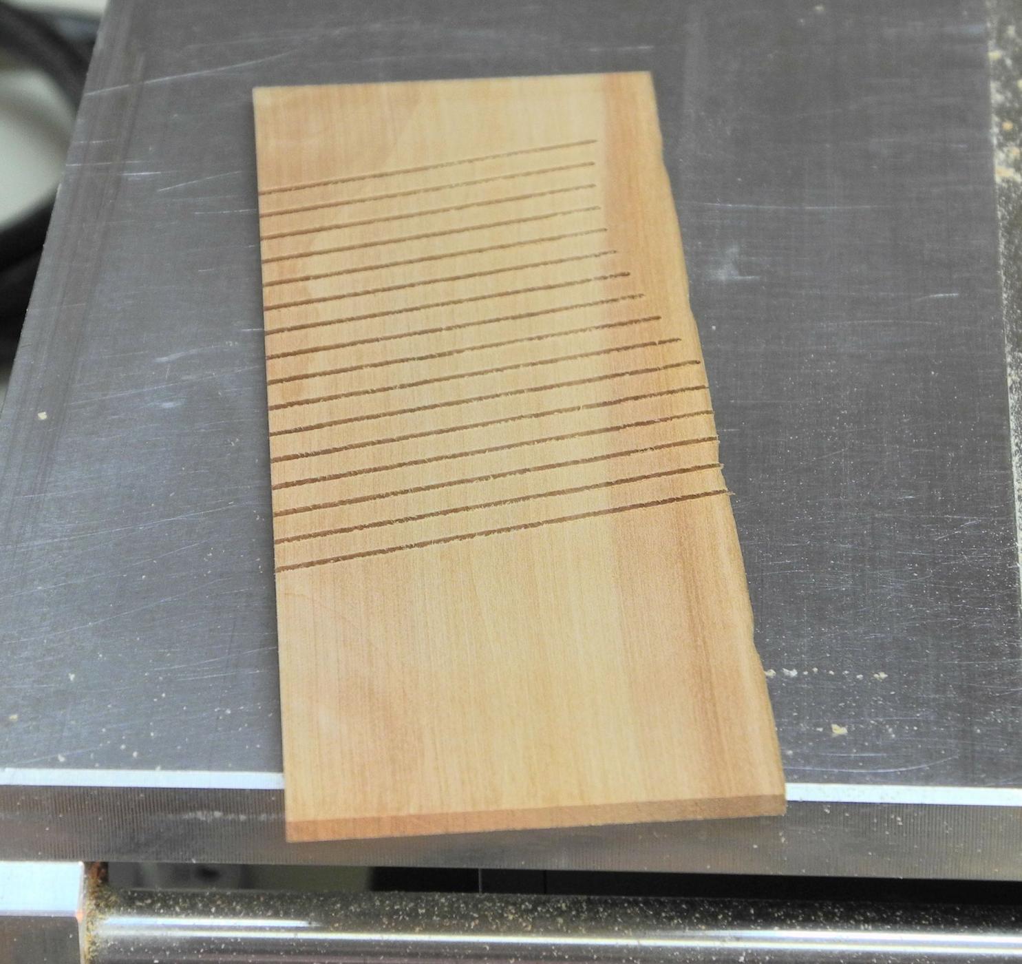
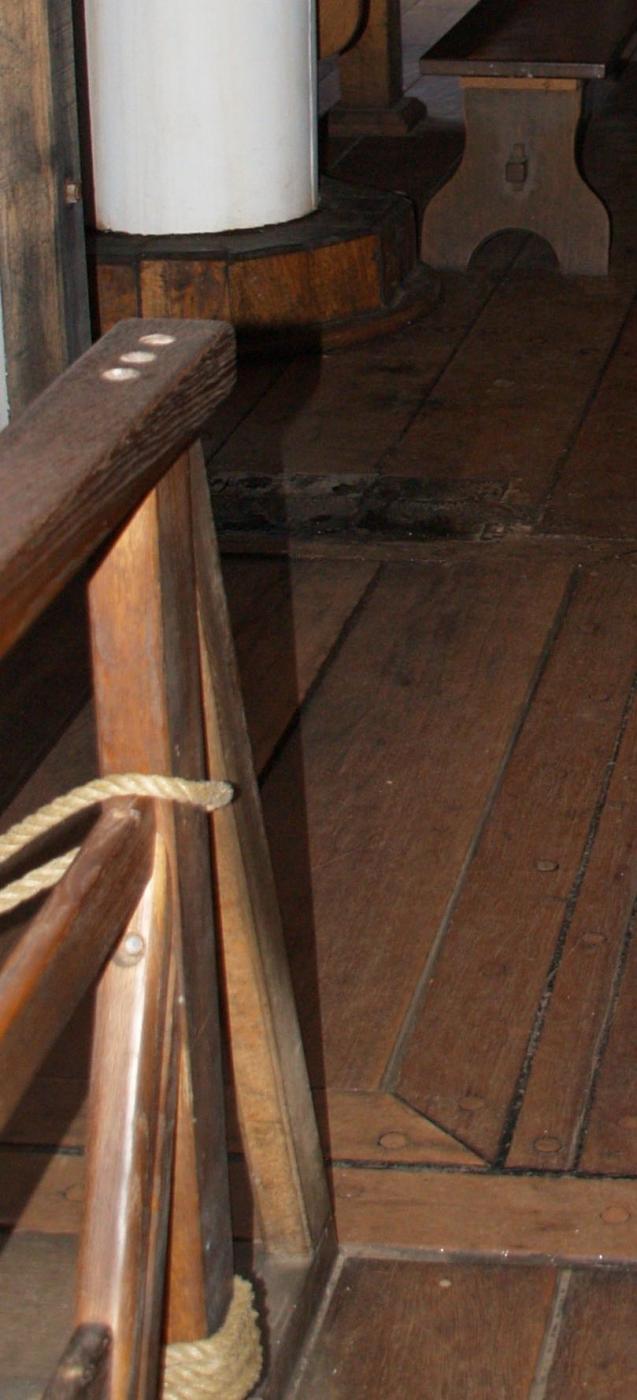
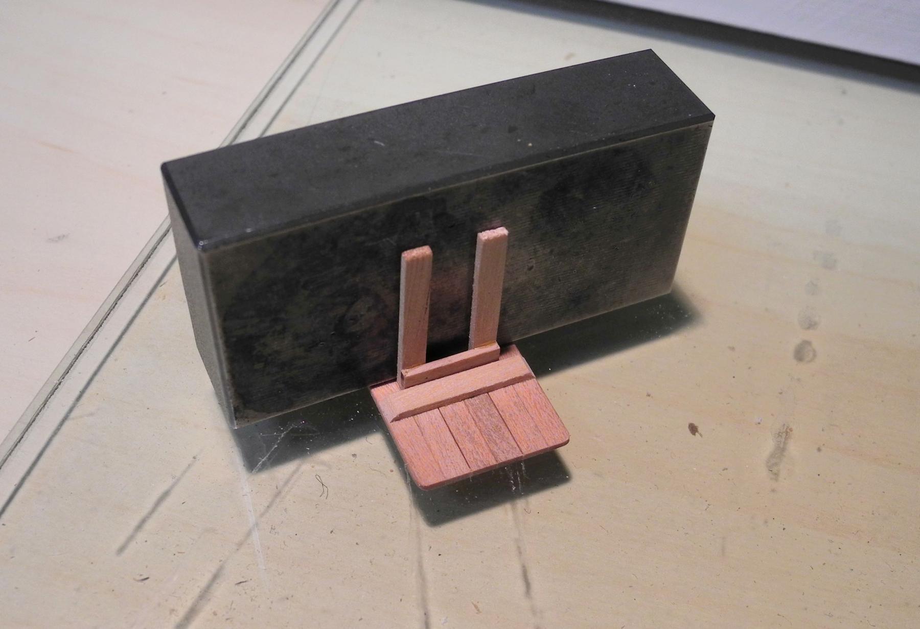
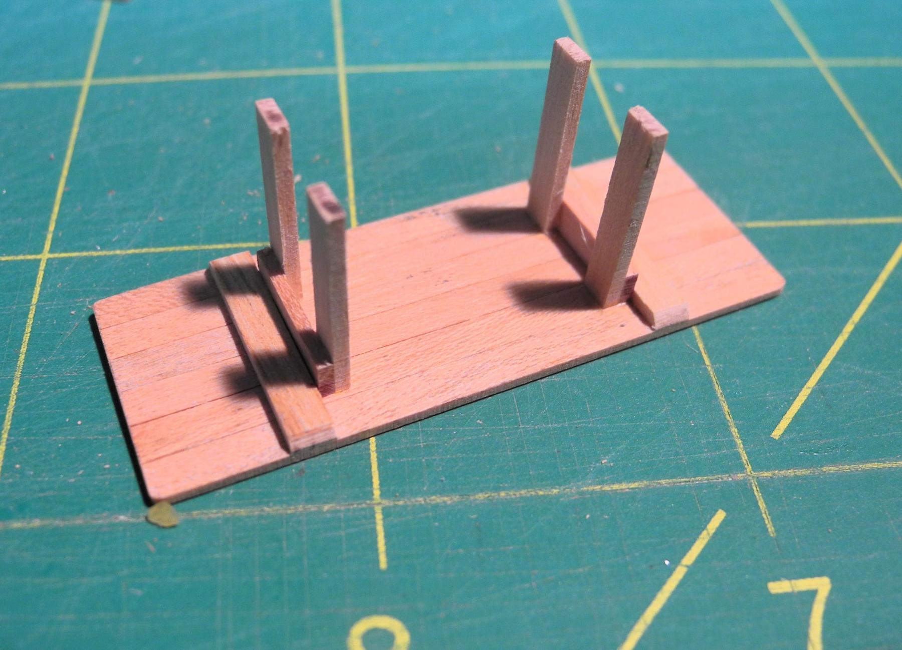
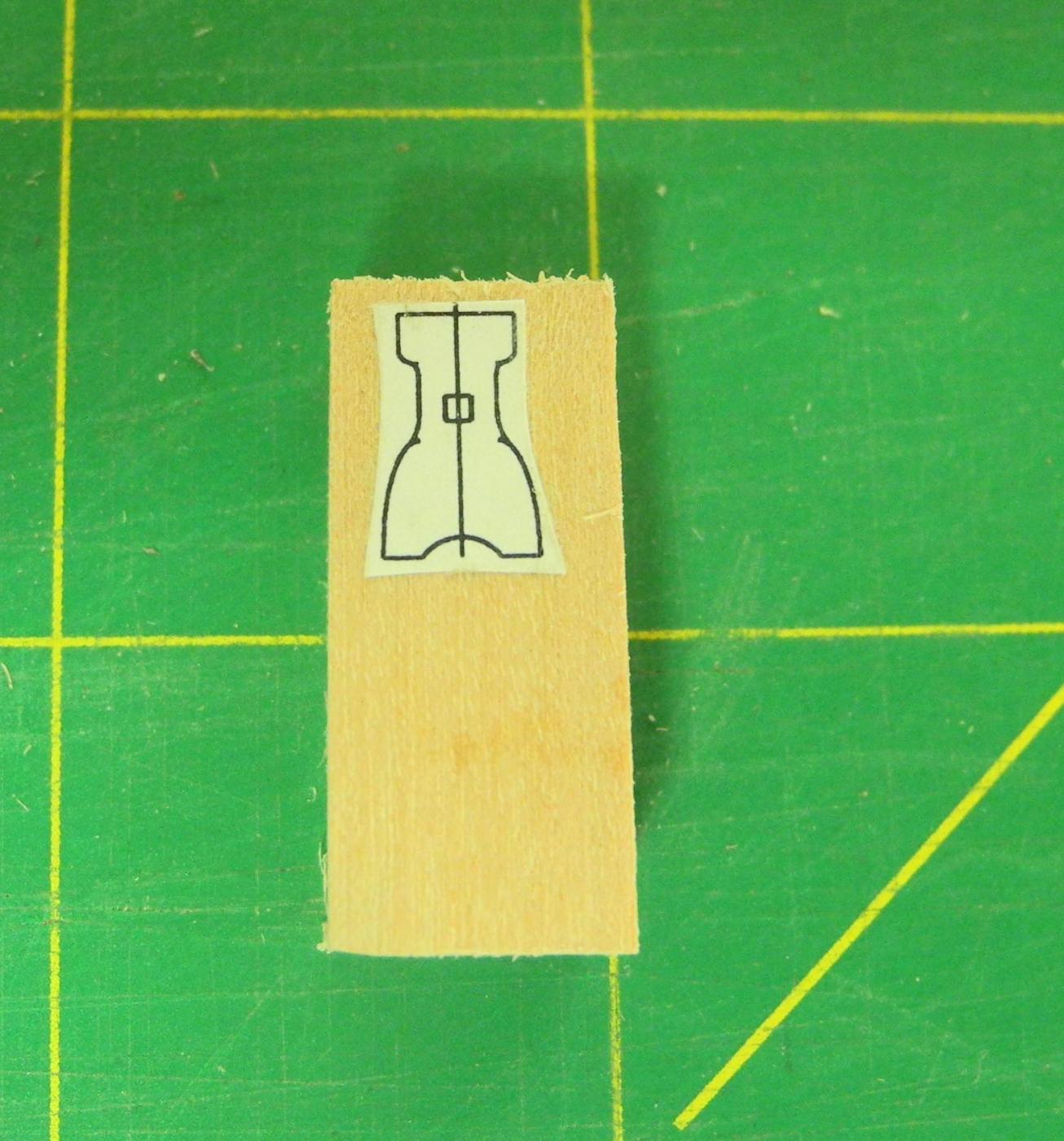
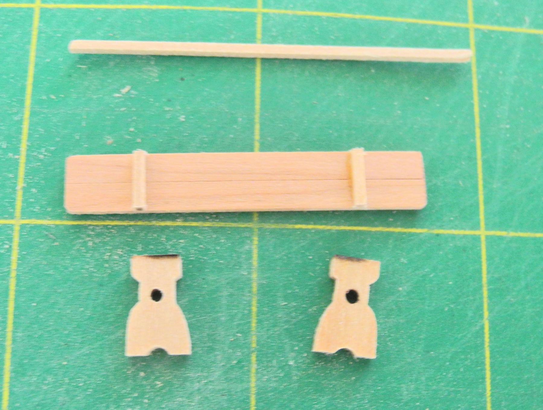
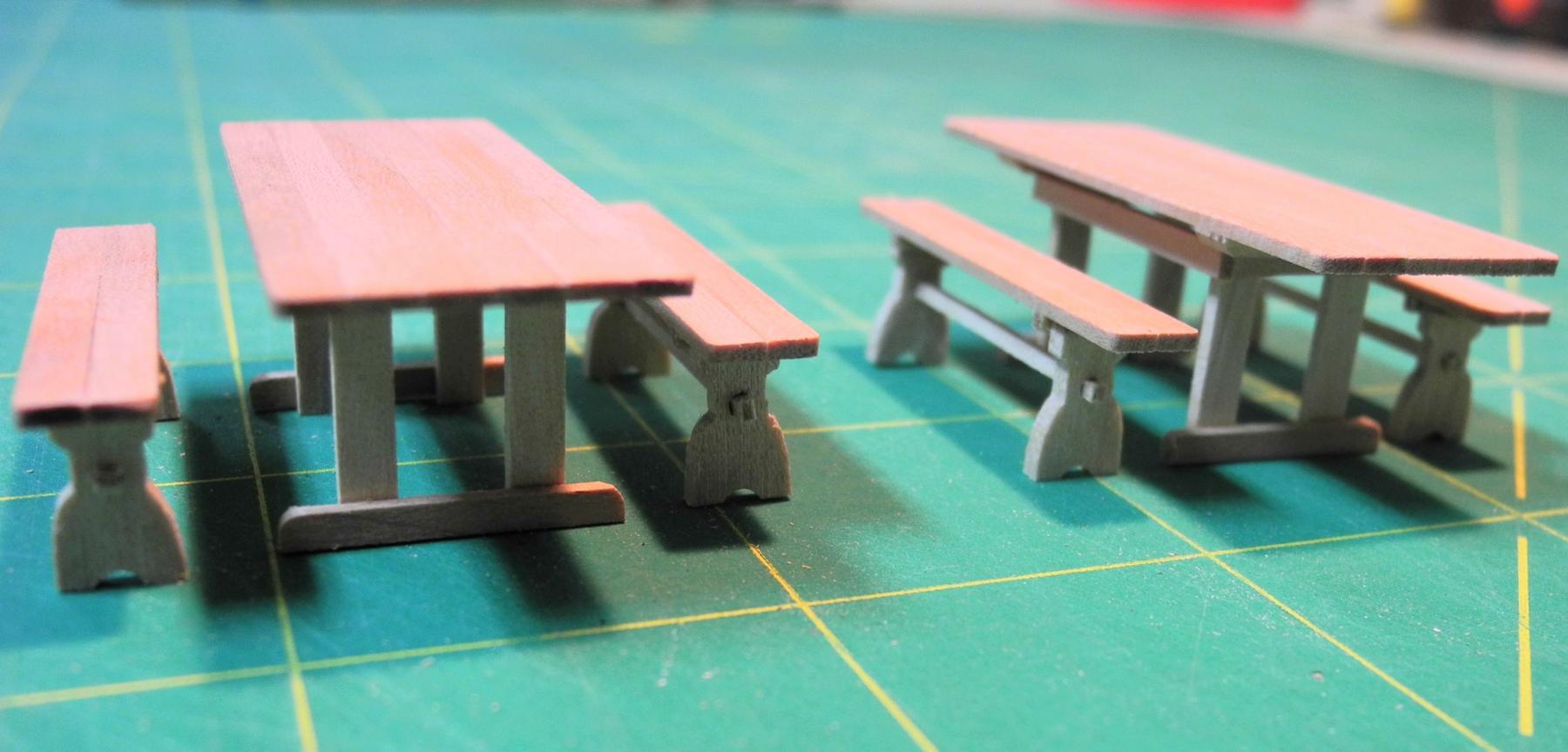
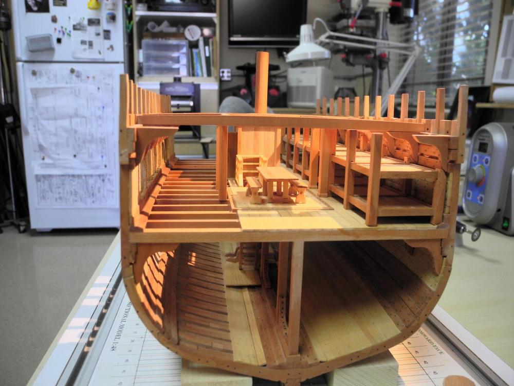
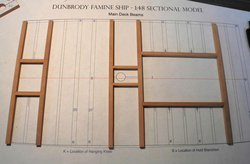
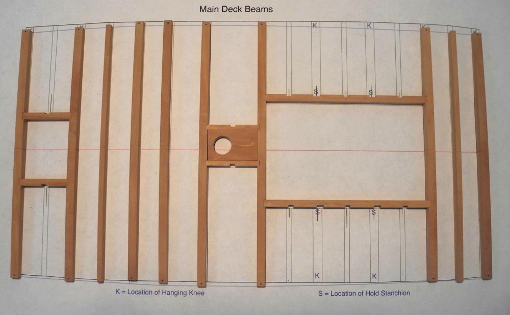
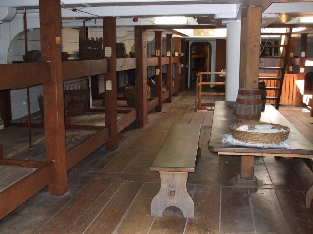
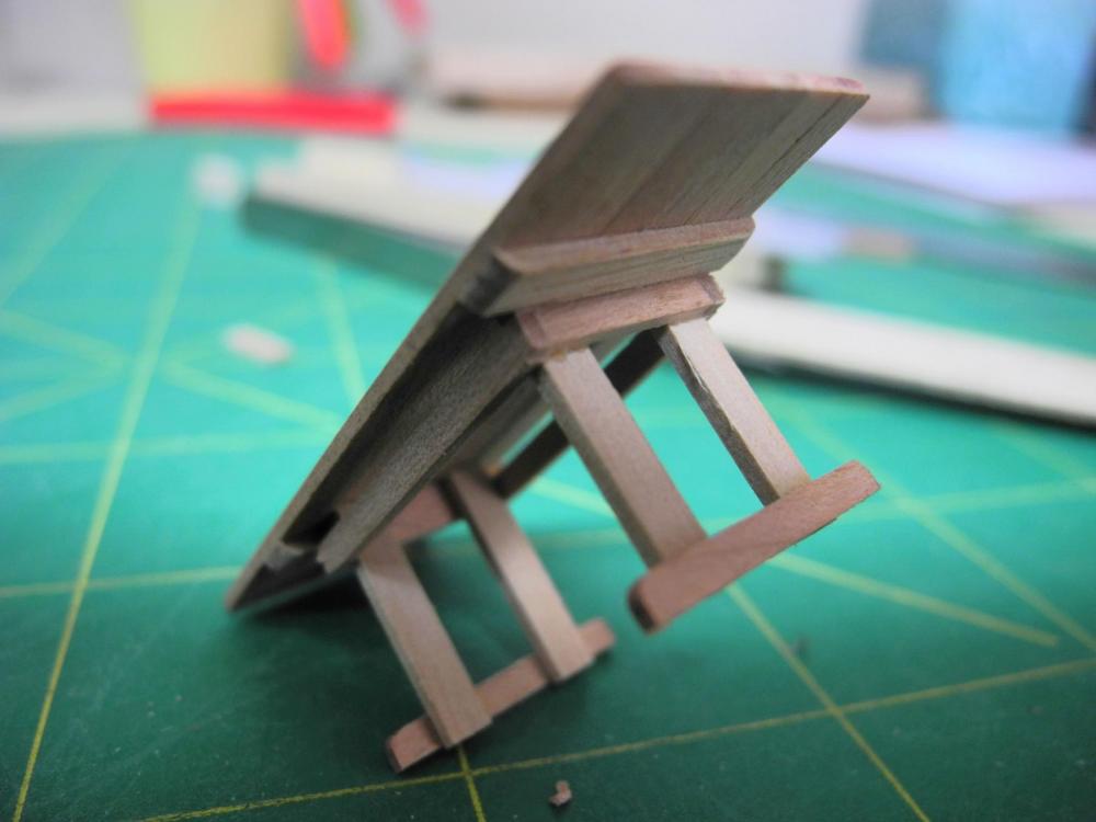
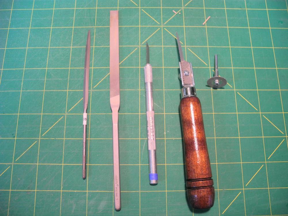
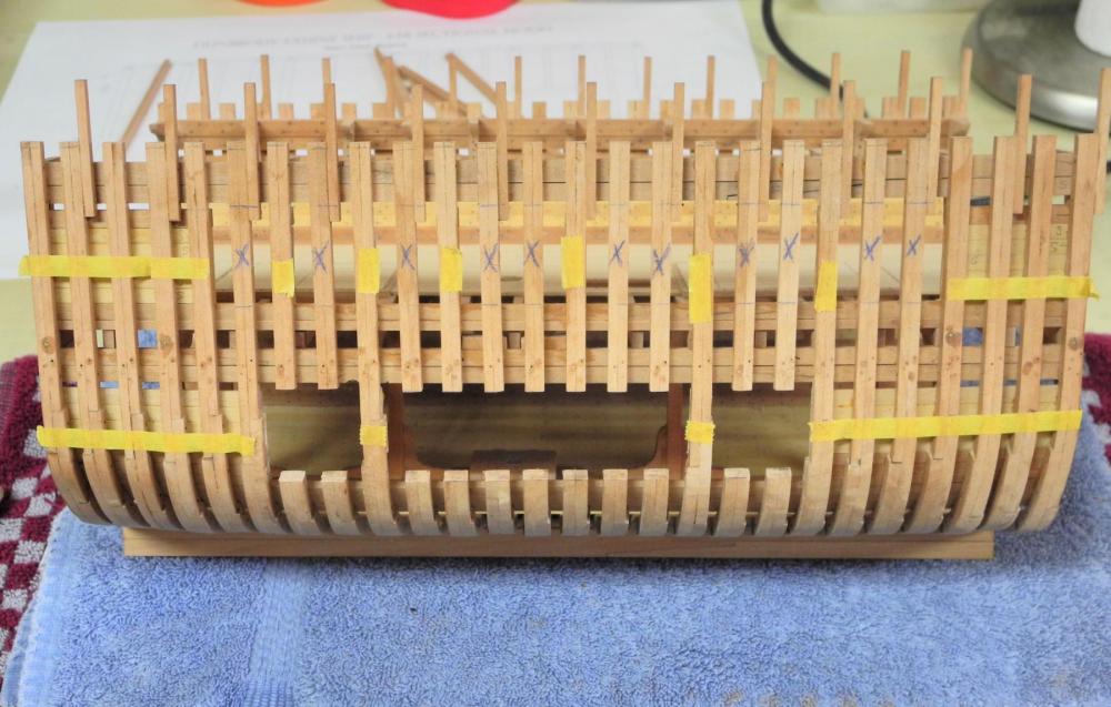
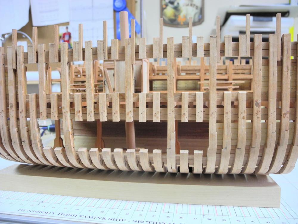
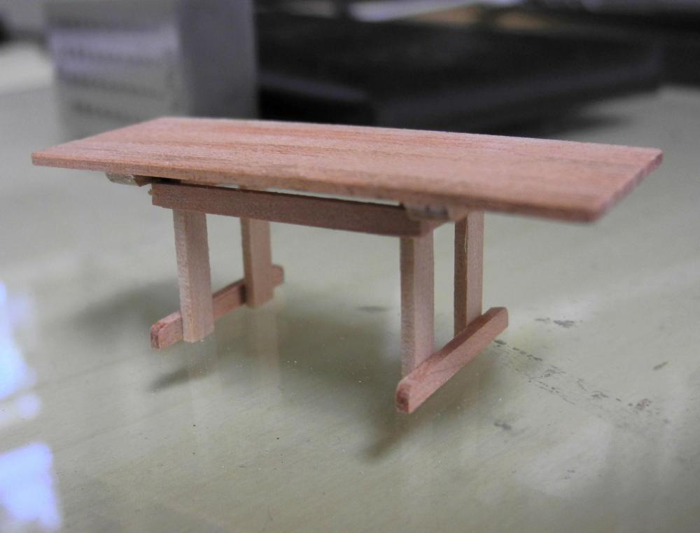
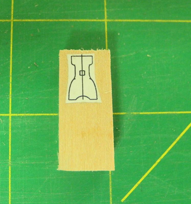
Part 37 – Mast Partners and Beams, Tables and Benches, Viewing Ports It has been a fairly productive few days on Dunbrody. Main Deck Beams First, I made the mast partners and prepped the main deck beams, starting by notching the two beams that have the mast partner attached. The two pieces of the mast partners were fabricated and fit in place. The assembly was checked against the main mast. Then the beams for the side of the main hatch were joined to notches in the beams fore and aft of the hatch. The beams for the forward hatch were then prepared. All main beams are now ready for installation. Tables and Benches Two large tables and accompanying benches were provided for the emigrants, as in this photo from the replica ship. The table seems to be built around a pillar or stanchion, but the drawing from the Colin Mudie book shows the tables as free-standing (probably bolted or nailed to the deck). My assumption is that the replica ship’s tables are a permanent installation, whereas the actual ship had tables and benches that were for one voyage only and were discarded at the end of the voyage, similar to the sleeping platforms and lavatories. The tables for the model are ‘free-standing’, and measure 8’x36”. The benches are 6’x12”. The table top was made using a jig similar to the jigs for the lavatory walls. The table legs were also made in a jig – the difference is that the jig for the legs was designed so that the length of the legs was set by the edge of the jig. The legs were sanded to size while still in the jig When the legs are removed from the jig they are ready for installation. A square block held the legs in place as the glue set. Feet and longitudinal braces were added to the table. The tables were tested on the ship. The tables sit on the hatches, and are placed as far from the hold companionway as possible. The seats for the benches were also built using a jig. The legs for the benches, however, were made from a single piece. 8 pieces of stock were glued together using Ambroid glue. The drawing for the bench legs was glued to this stack, and the leg design was rough cut on the scroll saw and then finished with files. The stack of legs was then separated in a short bath of acetone. A longitudinal brace strengthens the bench legs. The tables and benches are completed and ready for installation. Viewing Ports Viewing ports are needed on the starboard side of the model, and it made sense to cut these ports out before any of the details were attached to the Accommodation Deck. This was the first time the model was removed from the building board. I was concerned about cutting into the side of the hull – any mistake could be disastrous. I glued together some of the old discarded frames from the scrap heap so that there was something to practice on. I tried several methods of cutting the frames, and wound up using a variety of tools on the ports. The cuts were started (where there was enough room) using a diamond cutting wheel on the rotary tool. The cuts were finished with two small saws – a keyhole saw and a small X-Acto saw. Final shaping was done with a #00 needle file and a larger #1Grobet file. Masking tape was used to lay out the lines for the ports, and when I was satisfied with the lay of these lines I marked the frames to be cut with the line and with a large X. The central portion of the Hold viewing port was the largest number of adjacent frames to be cut, so this seemed like a good place to start. The outside Hold viewing ports were then cut, and then the Accommodation Deck ports were cut. I positioned the fittings for the Accommodation Deck to see the effect of the viewing ports. There will be a little more filing required for the finish of the ports, but overall I’m satisfied with the results. The next work will consist of applying finish to the Accommodation Deck and its fixtures, building and installing the ladders for the Hold companionways, along with safety railings around the companionway openings, and then the installation of the main deck beams. Thanks everyone!


- 649 replies
-
- 23
-
-
- dunbrody
- famine ship
- (and 2 more)
-
Thank you Albert, Bob, and Ed! Your comments are always a source of encouragement for me.
- 649 replies
-
- 5
-
-
- dunbrody
- famine ship
- (and 2 more)
-
Highland Woodworking is a good source for bandsaw blades. http://www.highlandwoodworking.com/1814tpibandsawblades.aspx
-
Thanks Antony Thanks Patrick. Yeah, very much like our 'outhouse'. My wife said I should put a half-moon symbol on the doors. ..and maybe a corn cob nearby? By the end of the journey the whole deck must have reeked. Lots of folks probably never made it to the loo.
- 649 replies
-
- 5
-
-
- dunbrody
- famine ship
- (and 2 more)
-
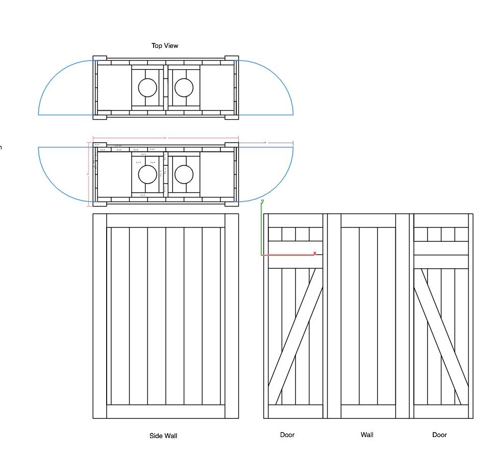
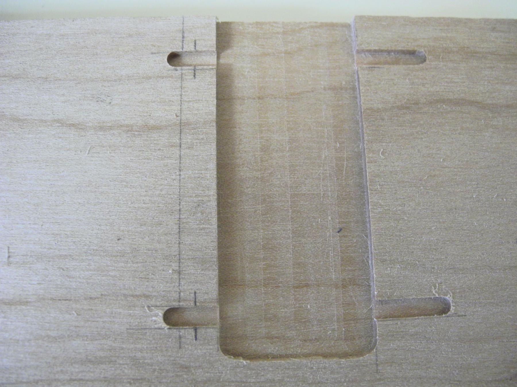
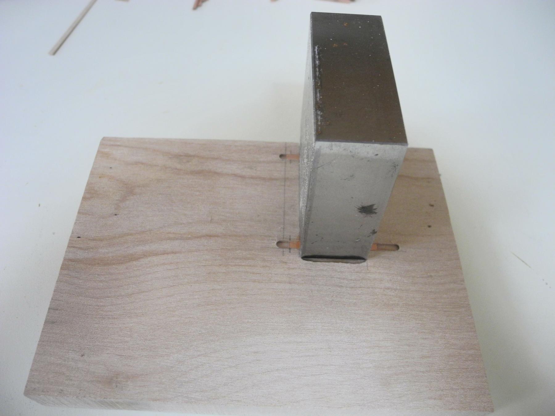
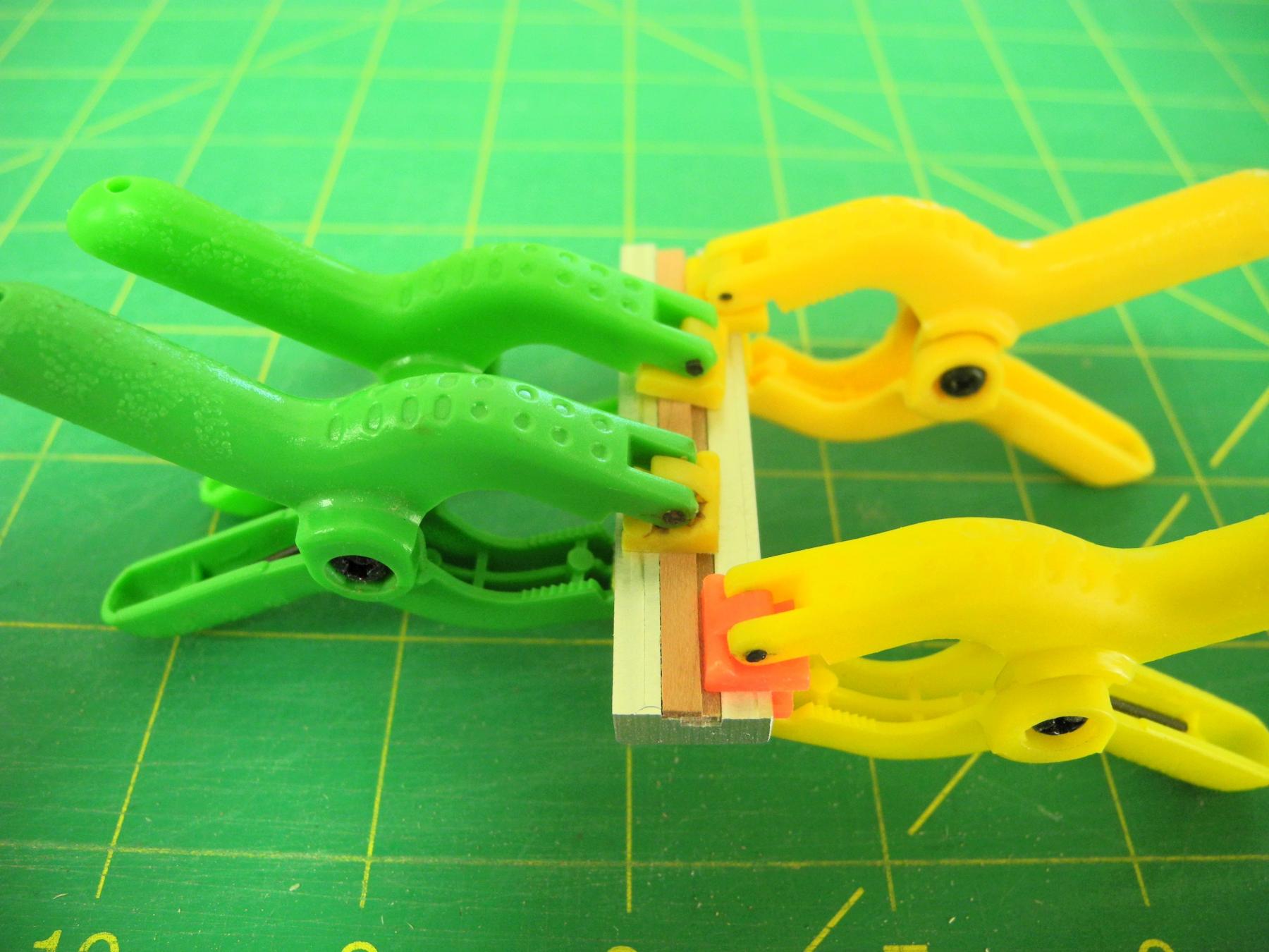
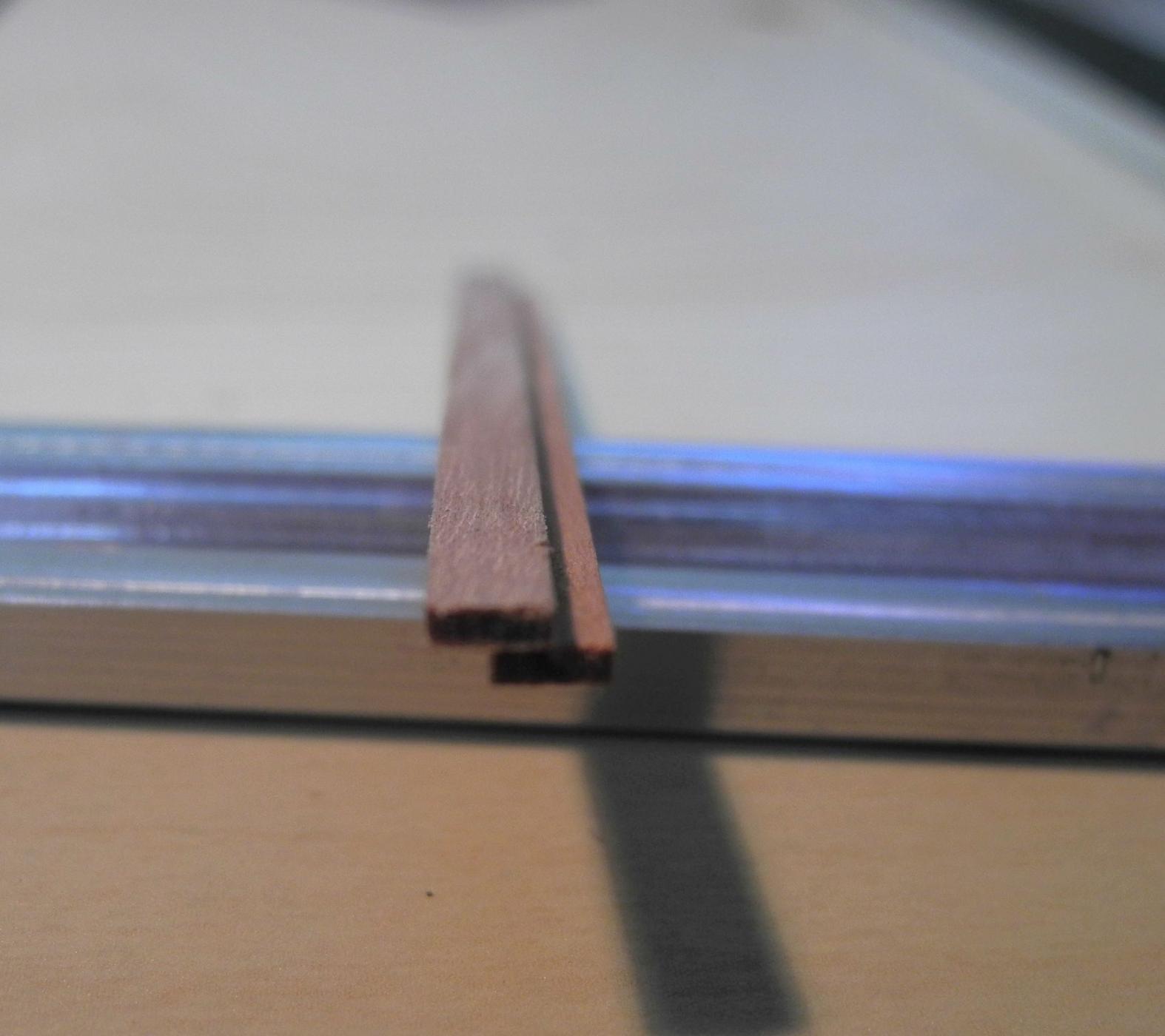
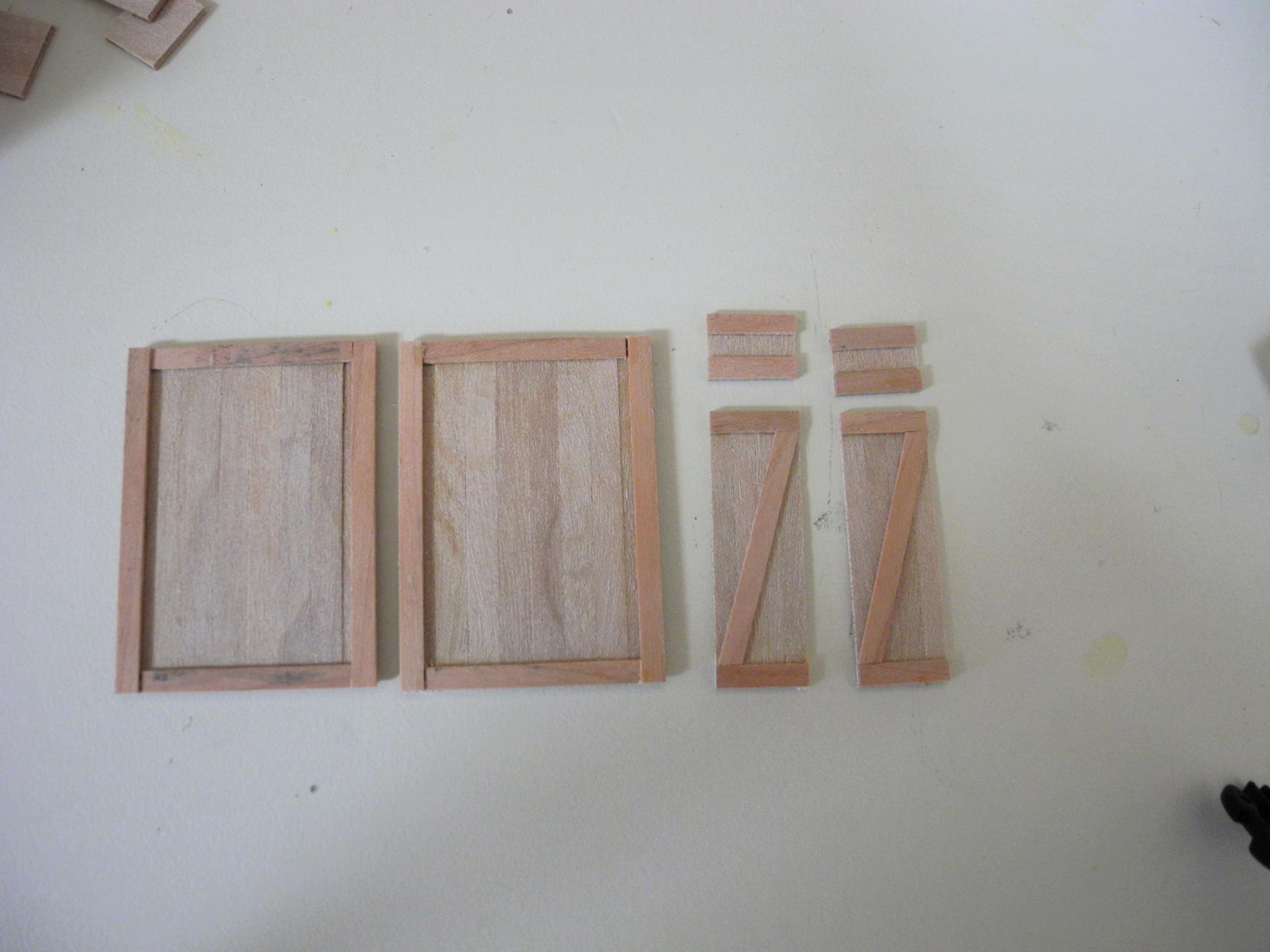
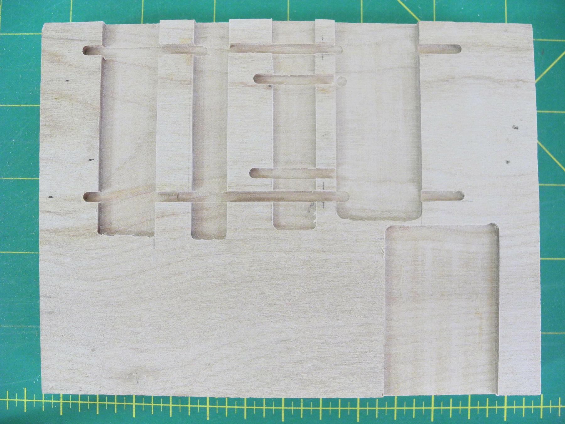
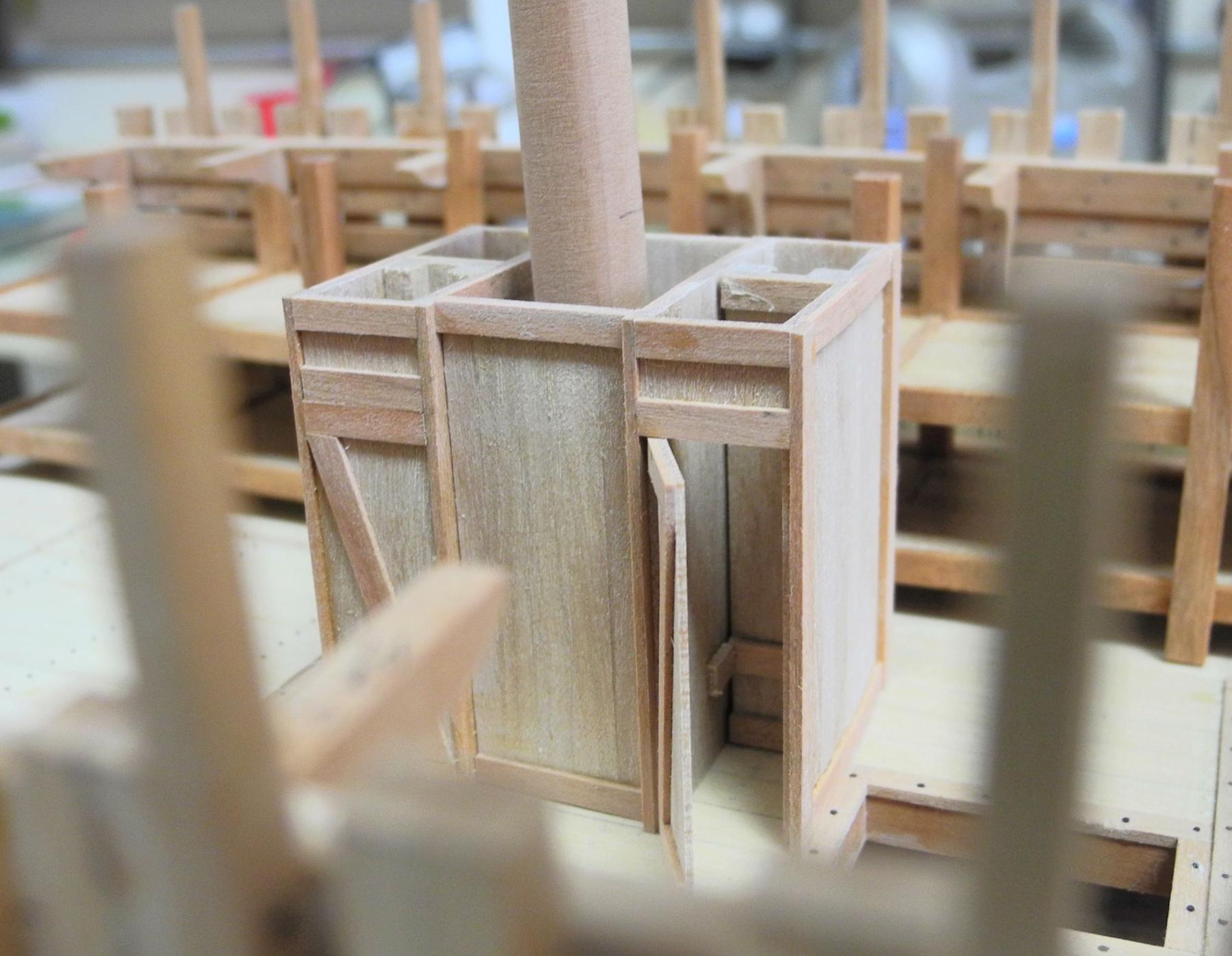
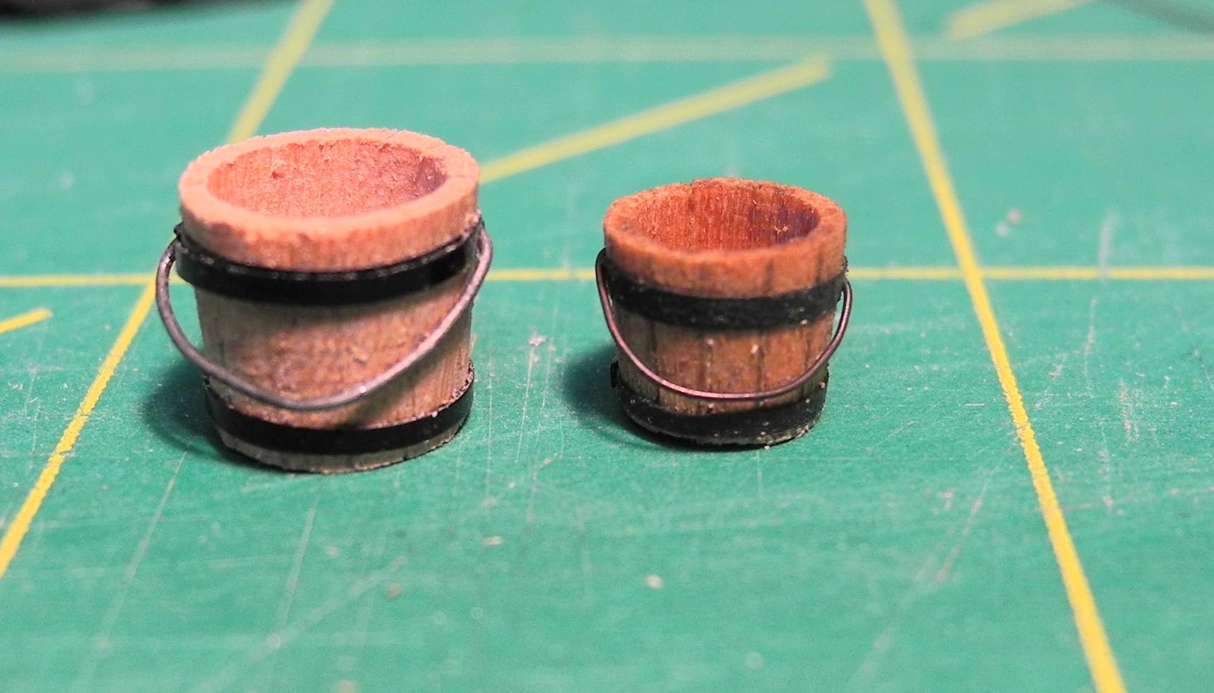
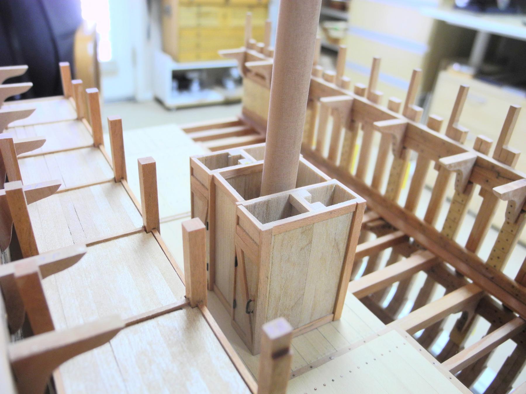
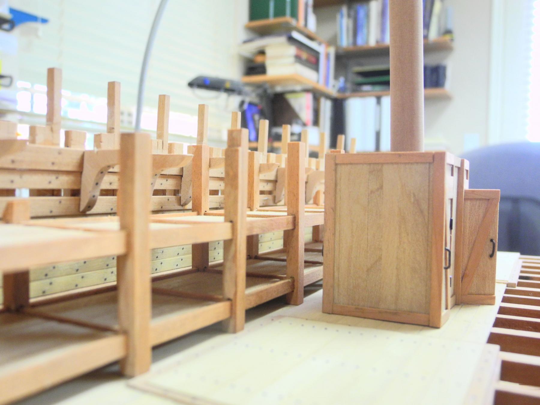
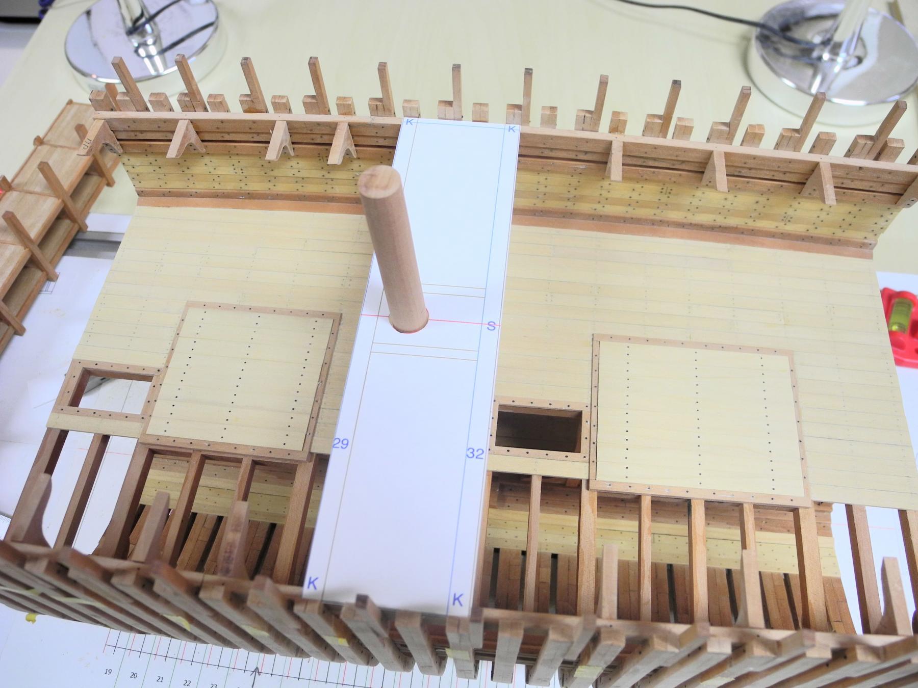
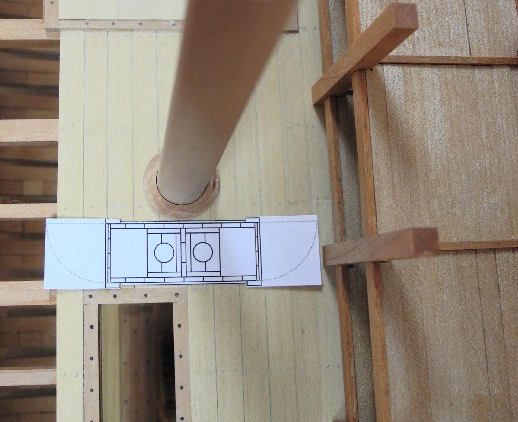
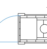
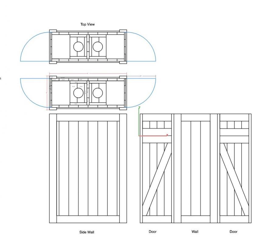
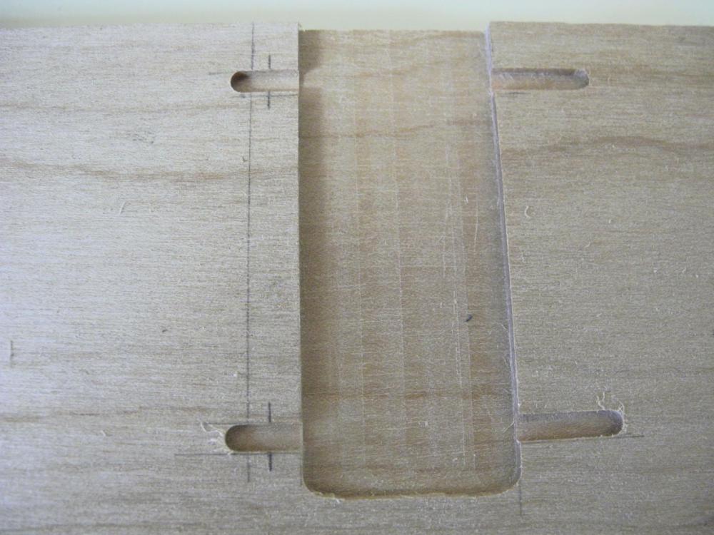
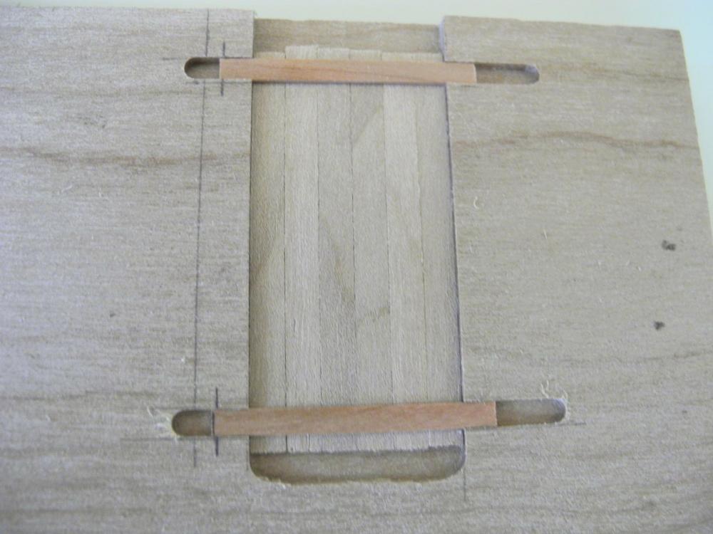
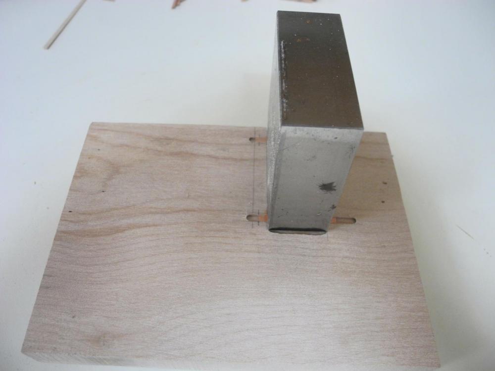
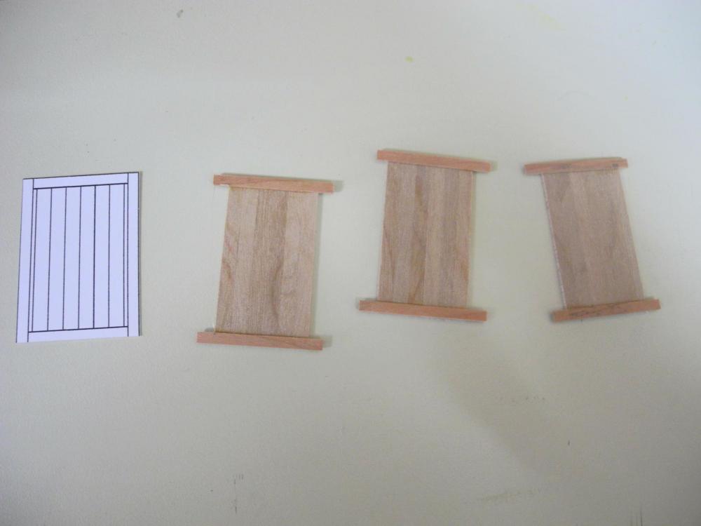
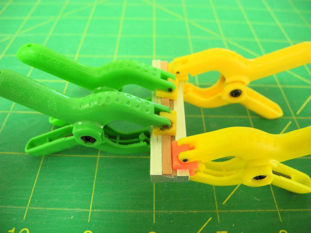
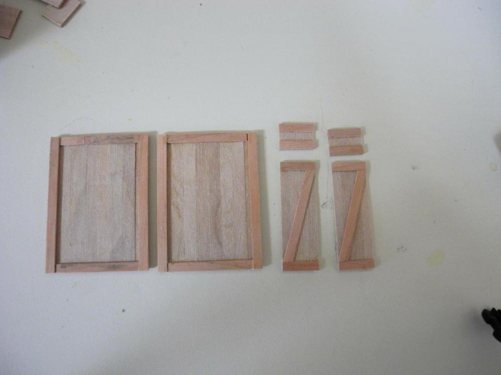
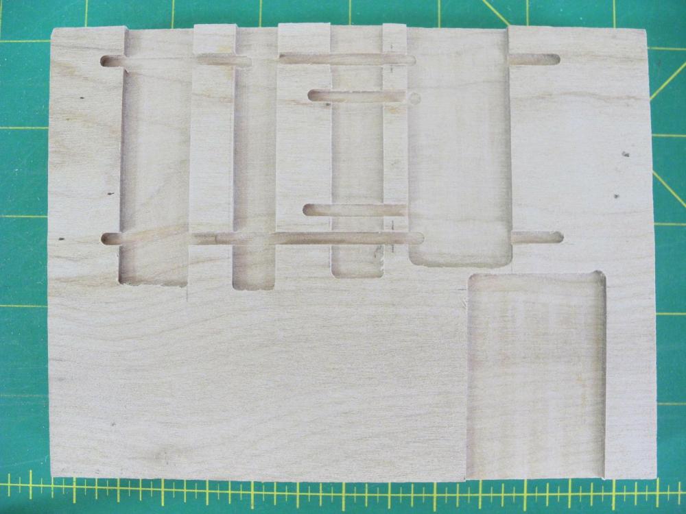
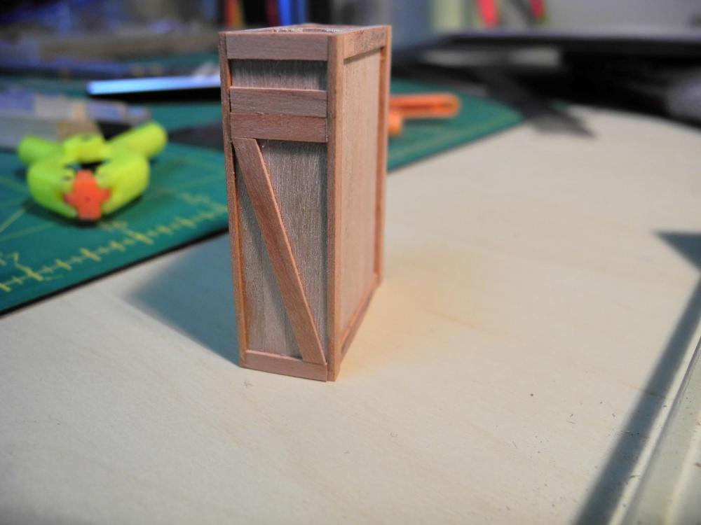
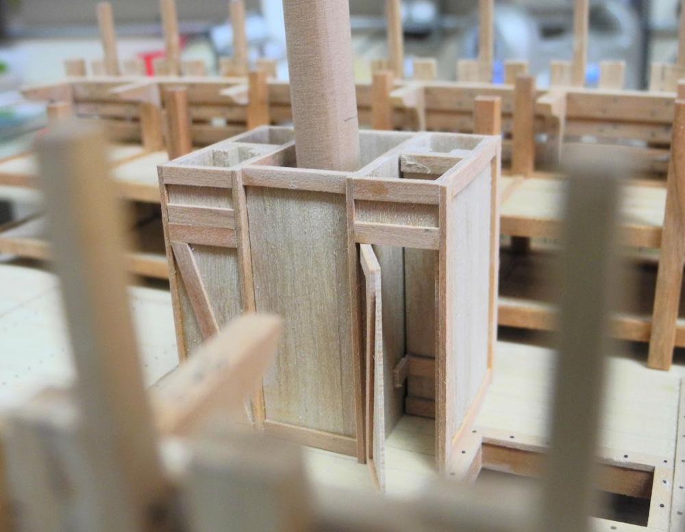
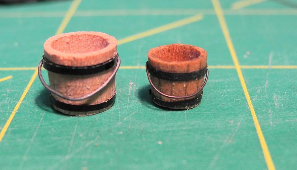
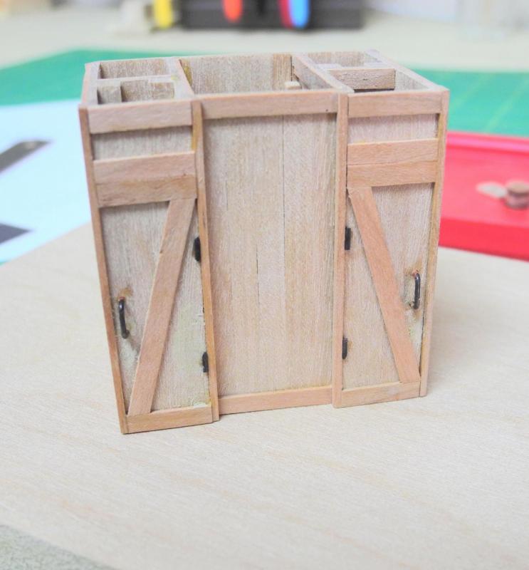
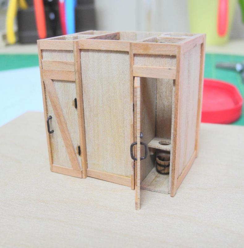
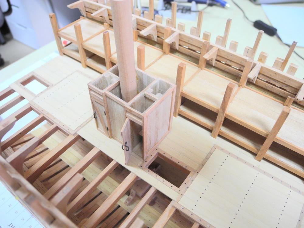
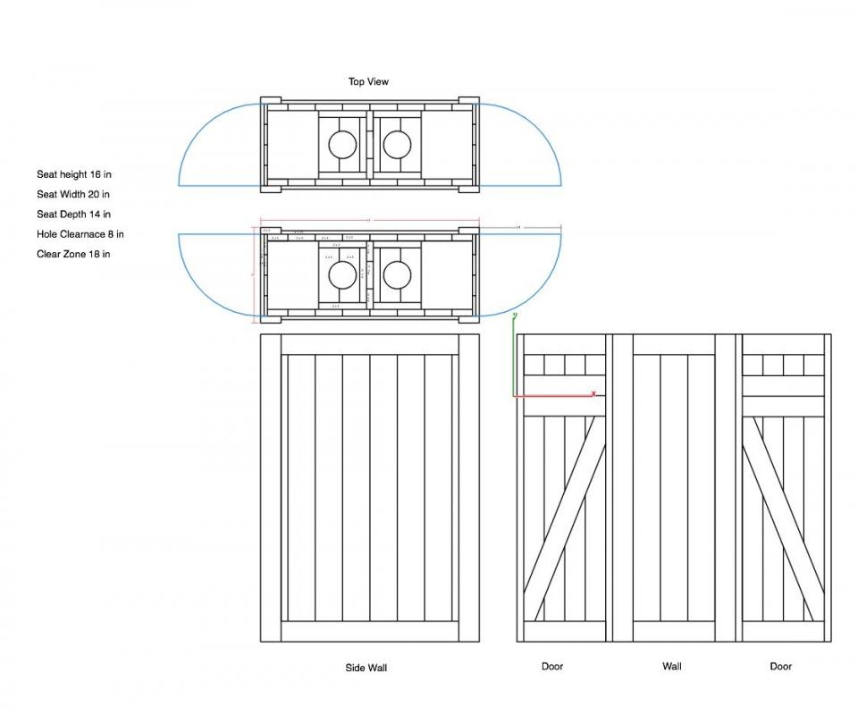
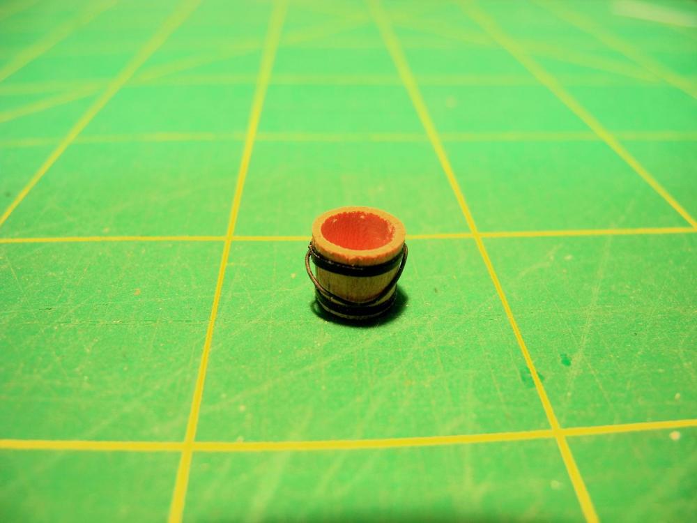
Part 36 – Bucket Lavatories Part 2 The Bucket Lavatories are made from a combination of beech and cherry. Because the lavatories were built as temporary fixtures, the plank dimensions were kept to a set of standard sizes that would have been available: 1 x 6, 1 x 8, 2 x 6, and 2 x 8. I thought about using 1 x 4 and 2 x 4, but felt that the very narrow planks would be difficult to manage. The following photo is the drawing for the lavatories. Most of the planks would be laid vertically, with horizontal planks at the bottom and top to tie all of the planks together. A jig was developed to keep the planks properly aligned vertically, and to ensure proper spacing between the horizontal planks. In use, the vertical planks were laid into the jig, then glue was applied to the horizontal planks and these planks were laid in place over the vertical planks. A weight was used instead of clamping. The following photo shows 3 of the sides after gluing, along with the drawing of the sides. The corners would be made of two 2 x 6’s, offset to each other, as in the following photo. A special jig was needed to ensure that the corner posts were straight and the offset was uniform. The jig was made form aluminum so that any excess PVA glue would not adhere to the jig. Four clamps were used with the jig. The yellow clamps served two purposes: they kept the bottom plank in place, but through sideways pressure they also kept the top plank pressed against the side of the jig to keep it straight. The green clamps applied the downward pressure to adhere the two clamps together. The following photos depict the corner posts after gluing. The lavatories consist of two back-to-back units on each side of the main mast (forward and aft), and are made from the following components. The concept for making the jig shown earlier was carried forward for each type of component. The following photo shows a completed double lavatory. The two double lavatories are joined by a planked wall that closes off the main mast (and hides the mast wedges previously worked on!). The following photos show the test fitting of the lavatories and checking their height against the main deck beams. When it came time to test fit the bucket made in the previous post, it was apparent that that bucket was too large in comparison to the lavatories. So, a new bucket needed to be made – as in the following photo. The new bucket is significantly smaller. The doors on the port side are both closed But the starboard side, which will be seen through the viewing ports, has one door open The following photos show the lavatories in place, but not glued. There is just enough room between the lavatories and the sleeping platforms for the lavatory doors to open, but this makes for very tight quarters for the emigrants. Before gluing the lavatories in place I’ll be working on the mast partners for the main deck, which will be the topic of the next post. Thanks everyone!


- 649 replies
-
- 27
-
-
- dunbrody
- famine ship
- (and 2 more)
-
Thanks Druxey. I agree that it looks too clean - doesn't tell the story well enough that way. I may use some weathering on it, or a wash of burnt umber (but I don't want it to get too gross!)
- 649 replies
-
- 6
-
-
- dunbrody
- famine ship
- (and 2 more)
-
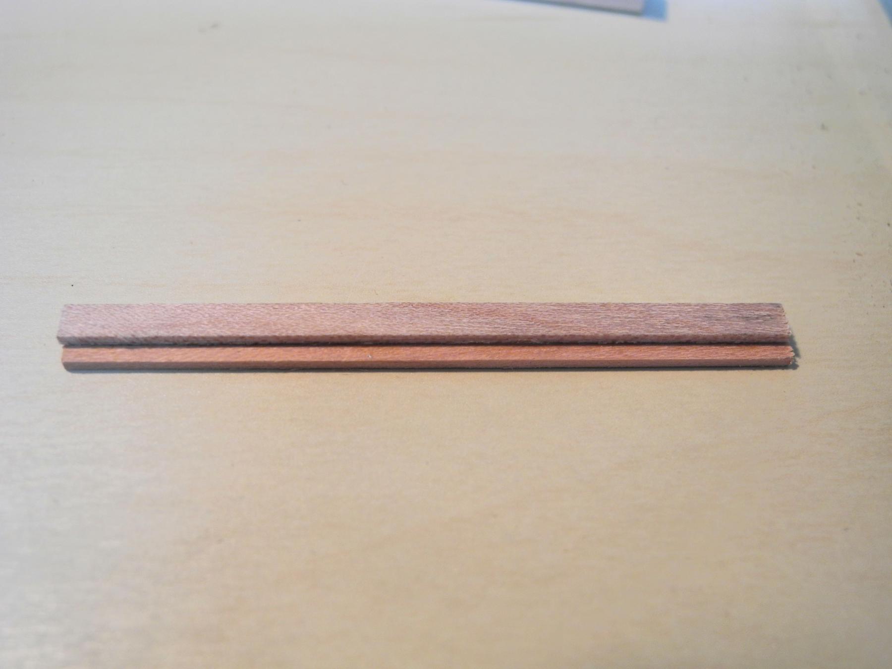
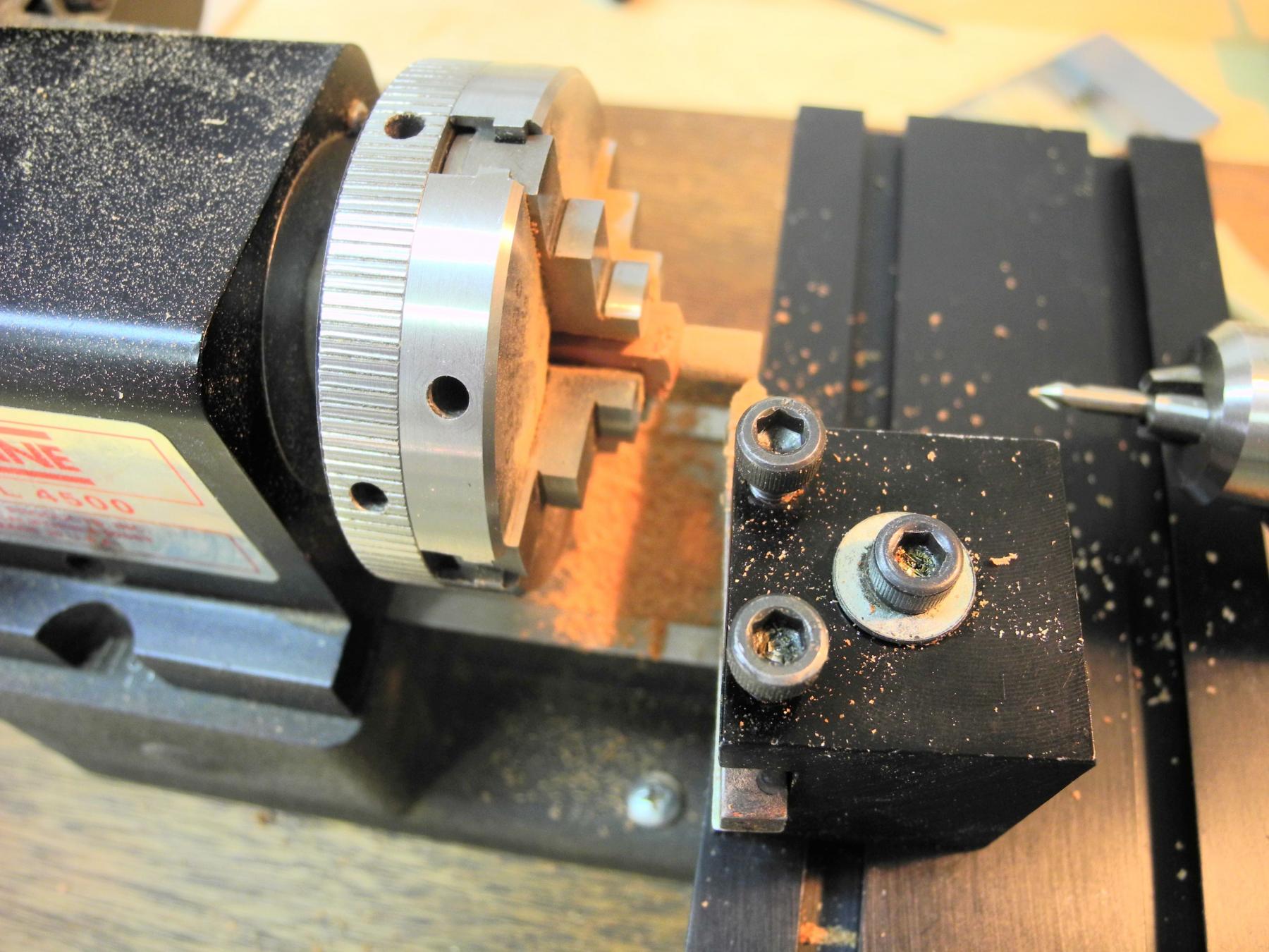
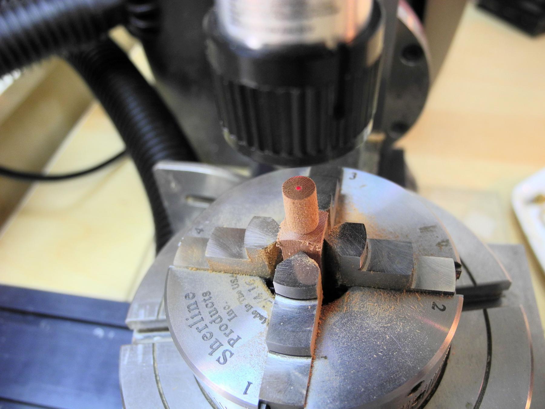
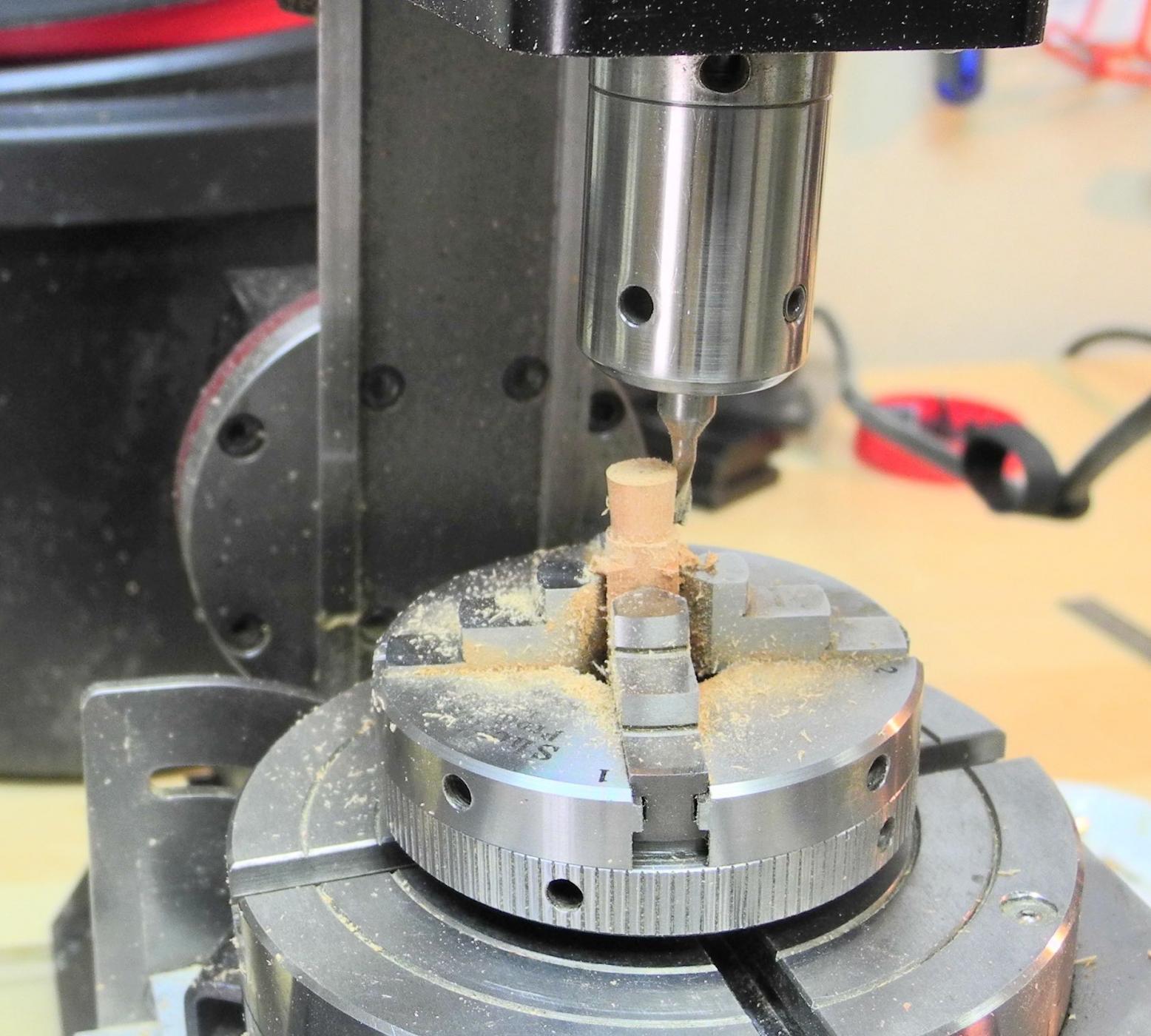
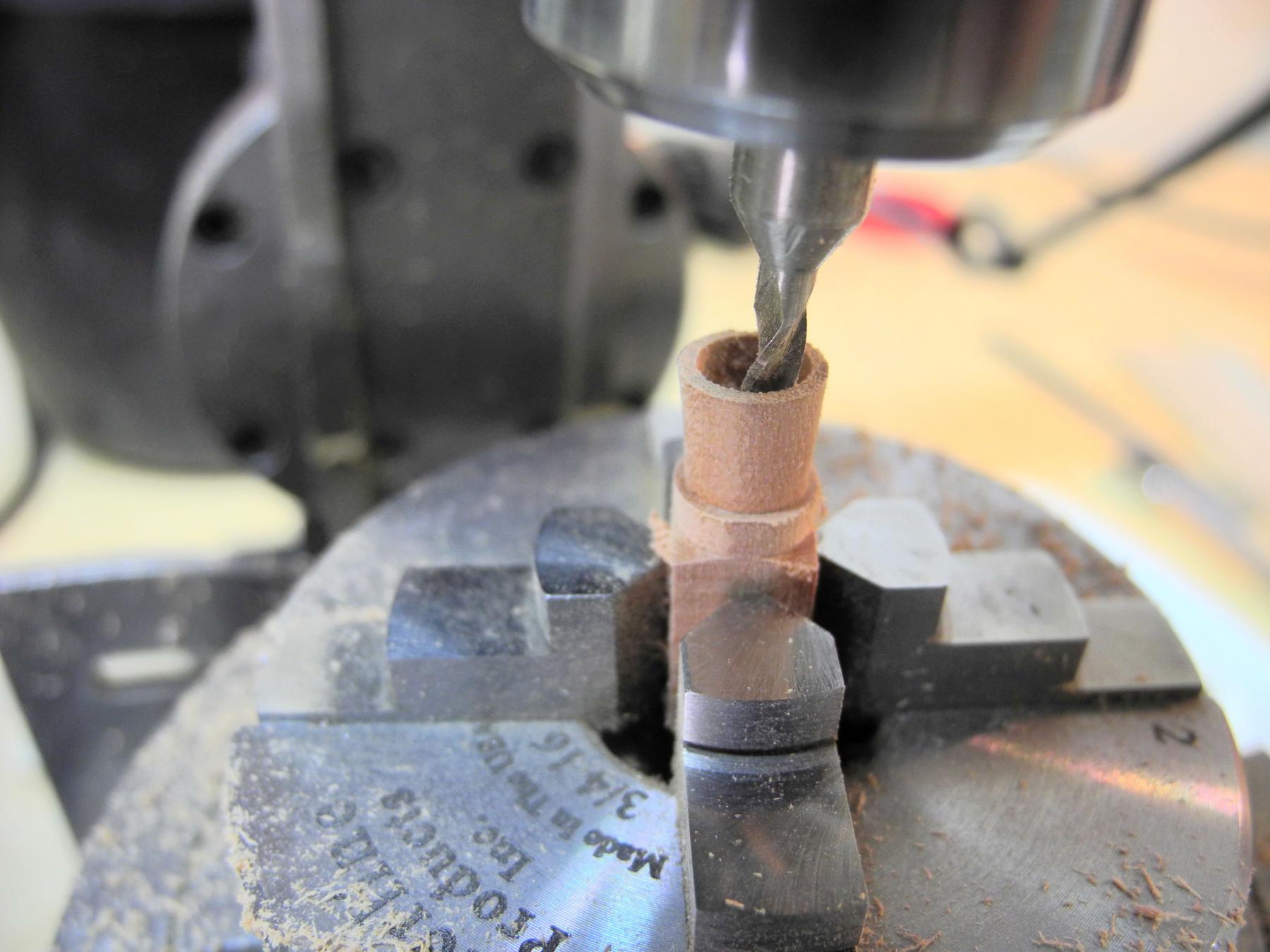
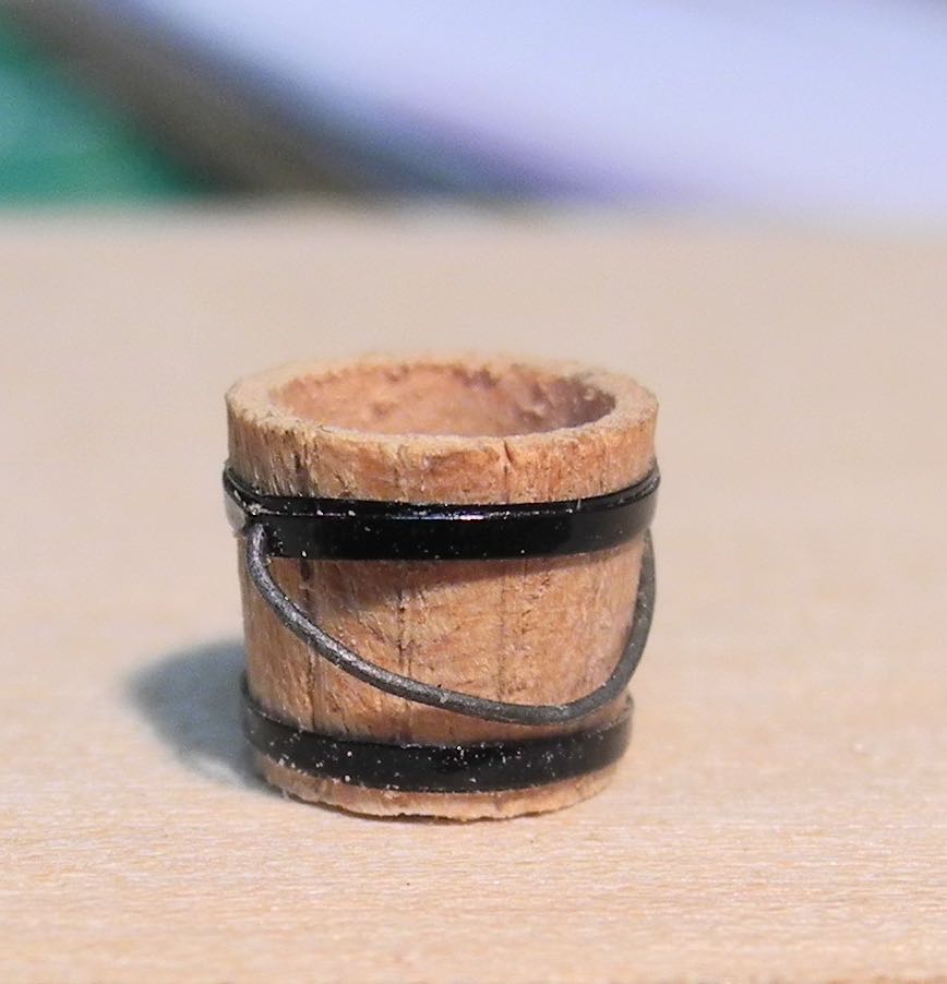
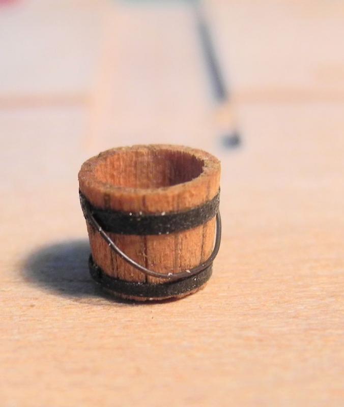
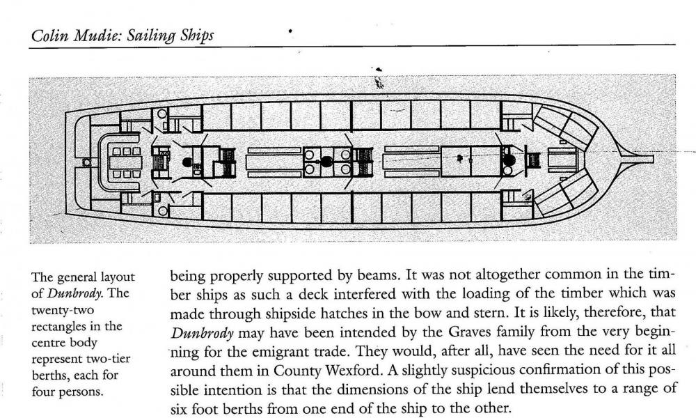
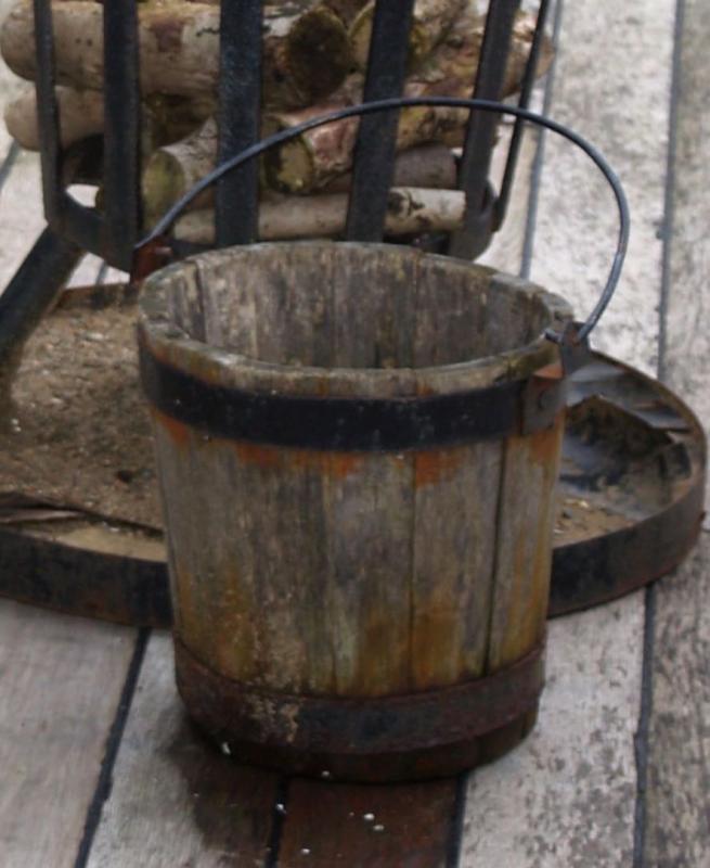
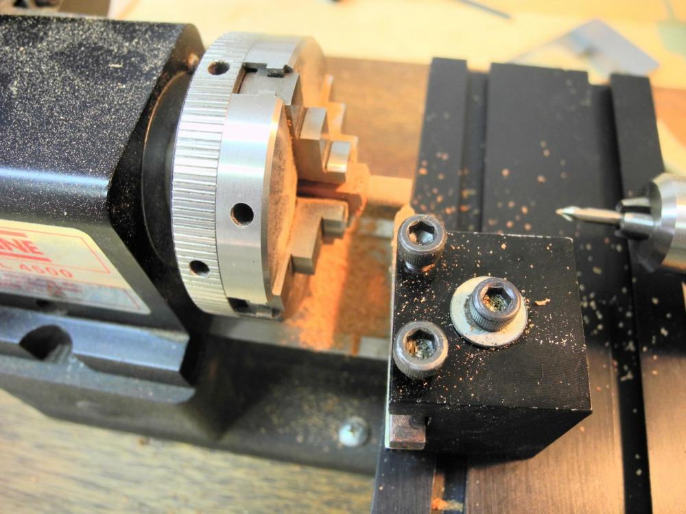
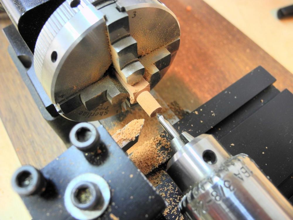
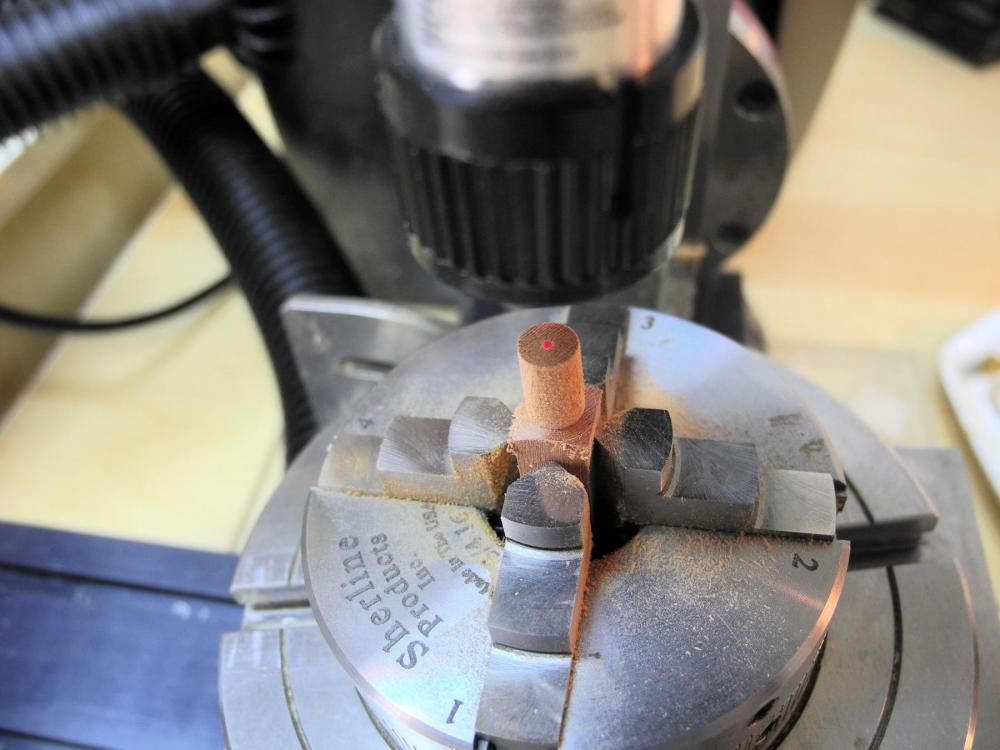
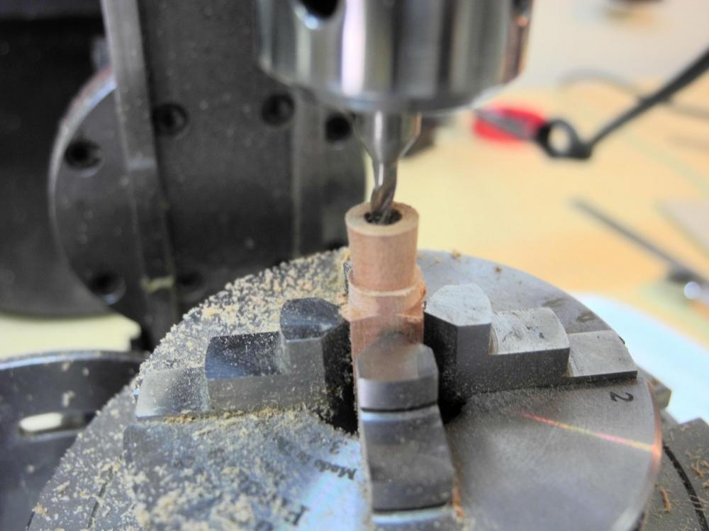
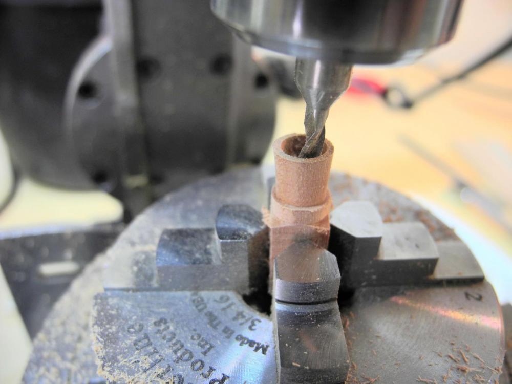
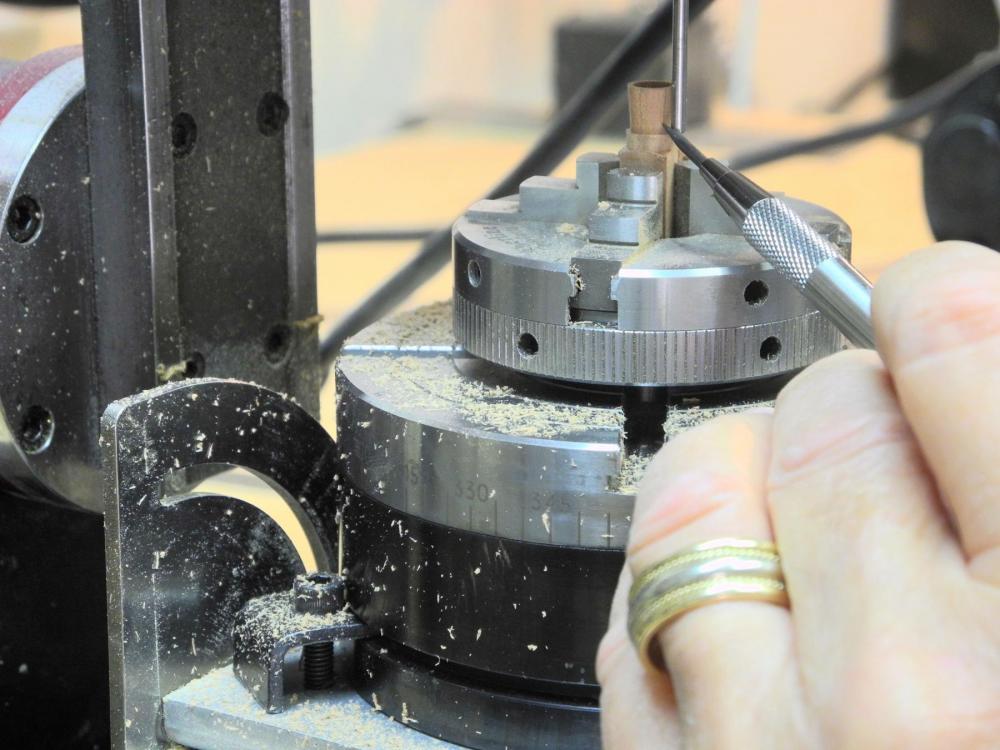
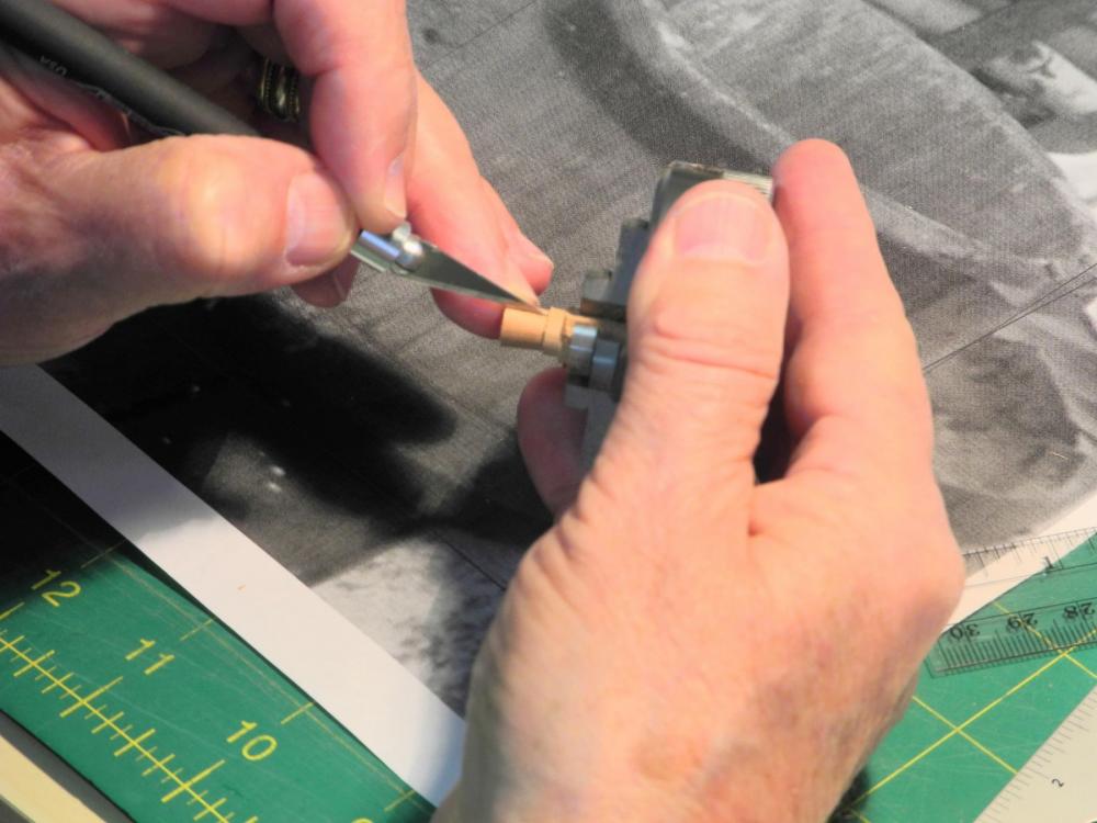
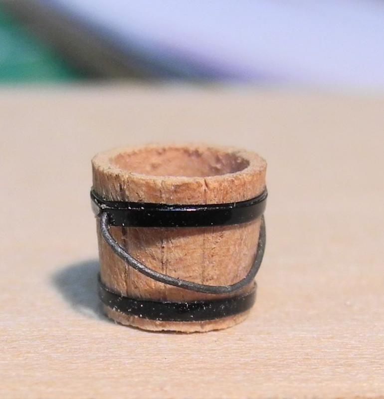
Part 35 – Bucket Lavatories Part 1 The Dunbrody had 4 ‘Bucket Lavatories’ on the Accommodation Deck, as shown in the central part of the attached drawing from the book by Colin Mudie, the designer of the replica ship. These 4 buckets serviced the 176 emigrants. The next photo was taken on the replica ship, showing the type of primitive buckets that were allowed for the emigrants. The Dunbrody web site gives the following: Lasting up to six weeks, the Atlantic crossing was a terrible trial for those brave, or desperate, enough to attempt it. Packed cheek by jowl below decks, the steerage passengers barely saw the light of day. Allowed up on deck for no more than one hour a day, in small groups, they would gather around open stoves to cook. When their time was up, it was back down into the dark, dank hold. During the regular storms the hatches were battened down, and the passengers would subsist on hard-tack biscuits. Hygiene was notoriously poor aboard most ships. With nothing more than buckets for toilets, and only sea-water to wash with, disease was rampant. Cholera and Typhus accounted for a great many deaths. Those who died were buried at sea. With death rates commonly reaching 20%, and horror stories of 50% dying, these vessels soon became known as ‘Coffin Ships’. The living conditions are hard to comprehend. My objective in building this model is to show the nature of the living conditions, so these lavatories are an important part of the model I’ve found that the various plans for the Dunbrody are not all in synch, and the arrangement of the bucket lavatories shown above will not fit on the model built from the available plans, so the arrangement I will build is somewhat different from the above drawing. These bucket lavatories were temporary and were built from rough lumber. The design of these lavatories for the model required a lot of drawing and redrawing. My opinion is that they were probably built with fairly light lumber and were probably thrown together in as simple a fashion as possible. I’ve tried to design them in that manner. One pair of the bucket lavatories fits between the main mast and the forward companionway. The available space is limited, so this dictates the size of both sets of bucket lavatories – one pair forward of the main mast and one pair aft. I want to leave one of the doors to the lavatories open so the viewer can see a bucket in place, so I decided to start with building one of these buckets. They’re very small, so I wanted to make sure I could actually make one that looks fairly realistic. The process started with turning a piece of stock to the appropriate size (1/4 inch diameter) then drilling a center hole in the workpiece The setup is similar to that used for the mast wedges: The 4-jaw chuck holding the workpiece was moved to the milling machine and mounted on the rotary table, which sits on the tilting angle table. The table is inclined to 5 degrees to conform to the shape of the bucket. The center hole was centered under the milling head using the laser centering device. The outside of the bucket was shaped first. The cutter was positioned to the outside of the workpiece at the appropriate depth, and the workpiece was brought to the cutter until the cutter barely touched the top of the workpiece. Then the rotary table was turned the full 360 degrees, resulting in the outside shape of the bucket. The cutter was raised and the workpiece centered under the cutter. The cutter was then lowered to the appropriate depth for the inside of the bucket. This started the hole for the inside of the bucket. The cutter was advanced on the y-axis and then the hole was milled by turning the rotary table through its full 360 degrees. This was repeated until the wall of the bucket was approximately 1/32 thick. A blank 3/32 shaft was mounted to the mill head using a collet, and the tilting angle table was lowered to 0 degrees. The blank shaft was used as a guide to mark the edges of the bucket’s slats by turning the rotary table in 30 degree increments and using the shaft as a guide for the pencil. The workpiece was removed form the mill, but was left in the chuck to allow me to hold it. The slats were then deepened by using a hobby knife followed by a small awl to widen the cuts. 1/16 black pinstriping tape was used for the metal bands around the bucket, and 28 gauge wire was used for the handle. My first attempt at a bucket turned out pretty well. I may decide to make a few more to be positioned on the Accommodation Deck and Main Deck. The first photo shows a very rough bucket, but when seen in actual size I’m pleased with it. Thanks everyone. Now I can proceed with building the lavatories themselves.


- 649 replies
-
- 20
-
-
- dunbrody
- famine ship
- (and 2 more)