Mahuna
-
Posts
1,504 -
Joined
-
Last visited
Content Type
Profiles
Forums
Gallery
Events
Everything posted by Mahuna
-
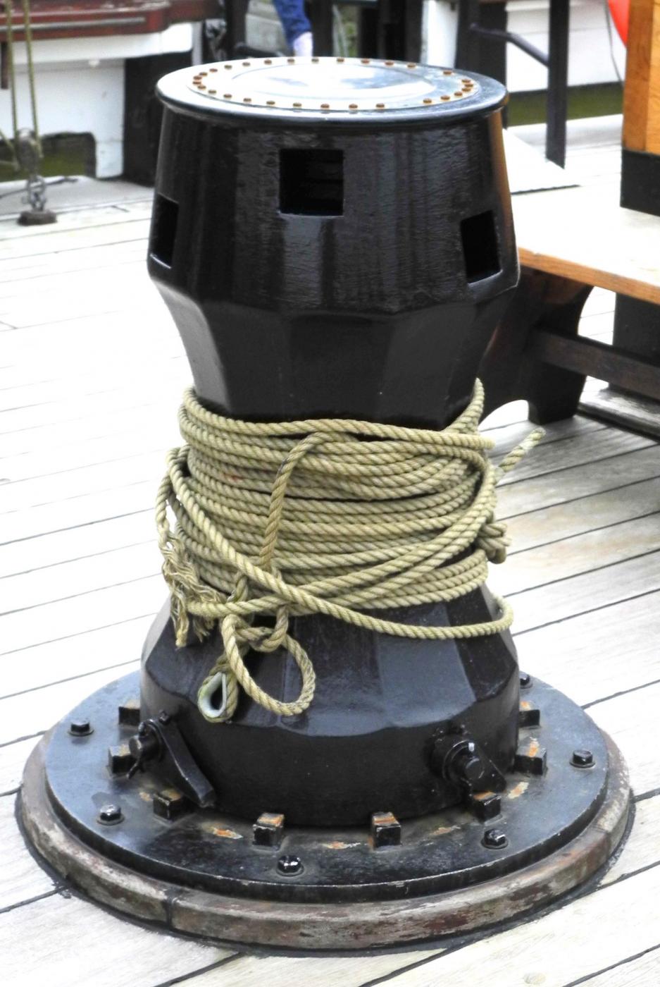
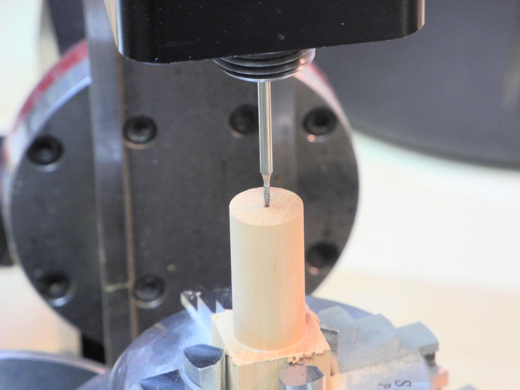
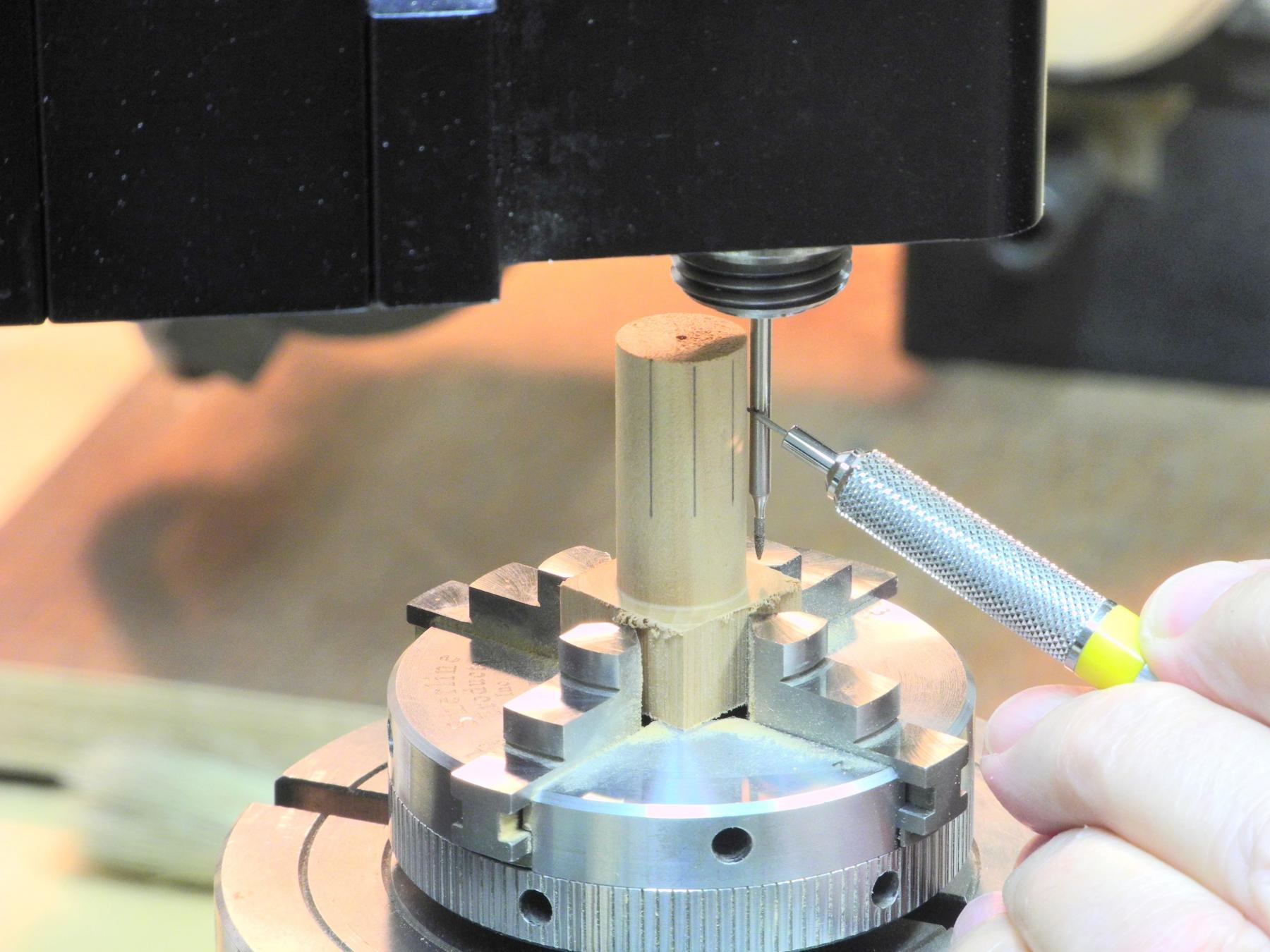
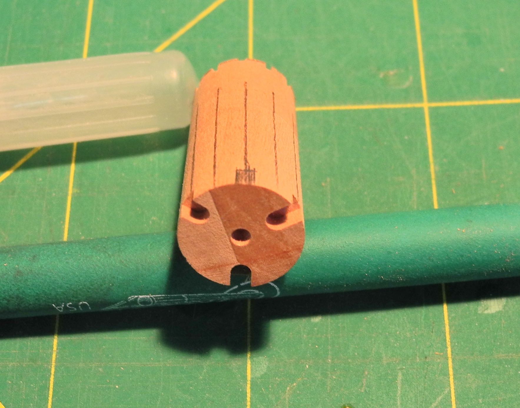
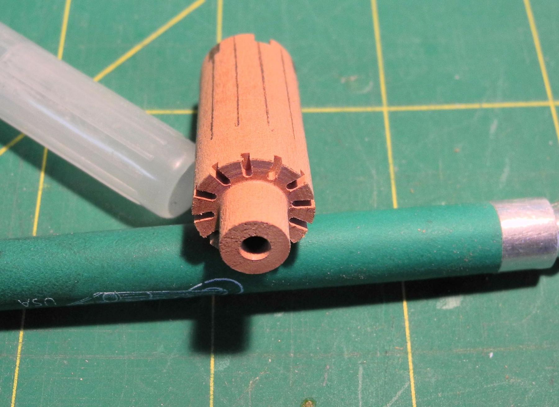
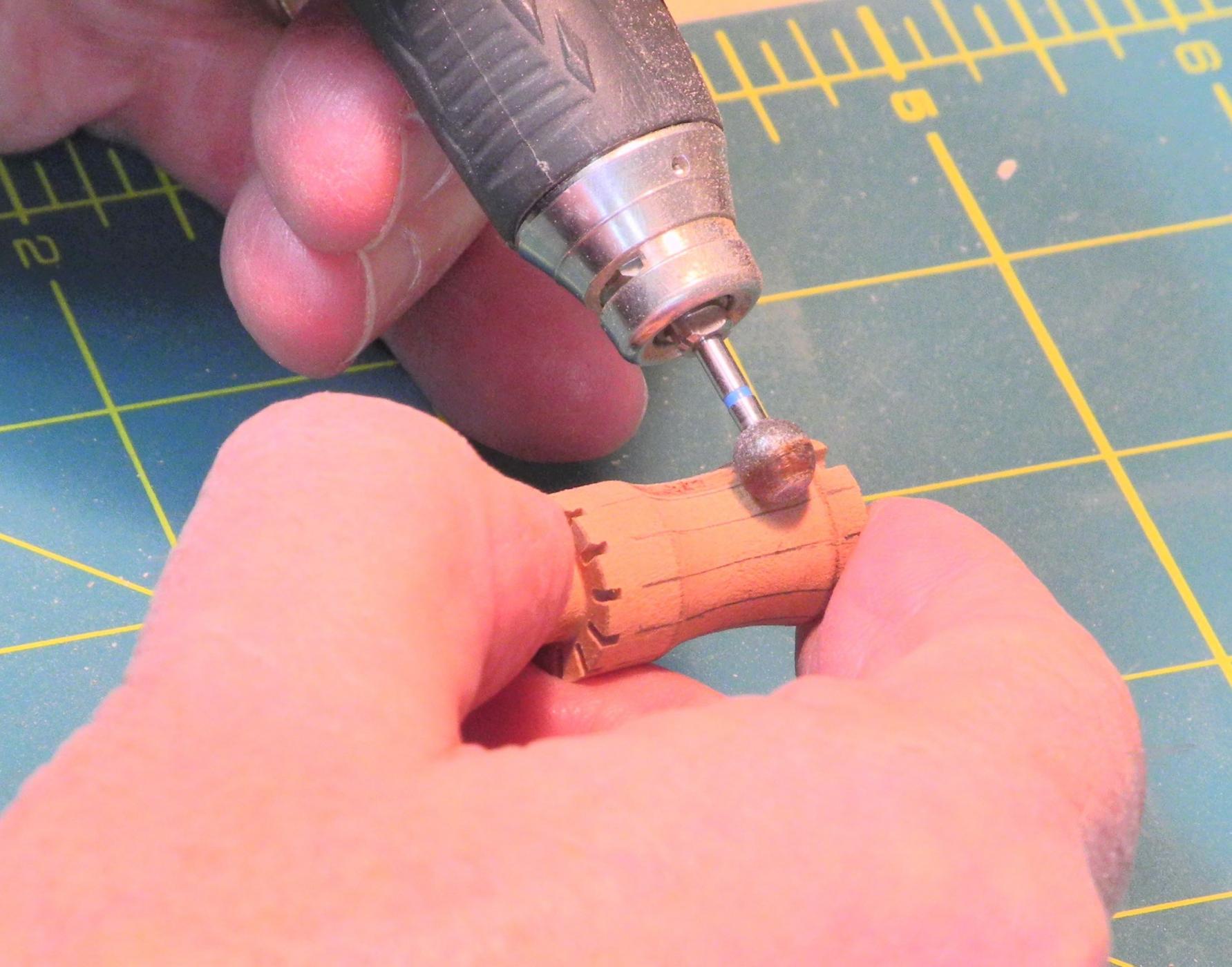
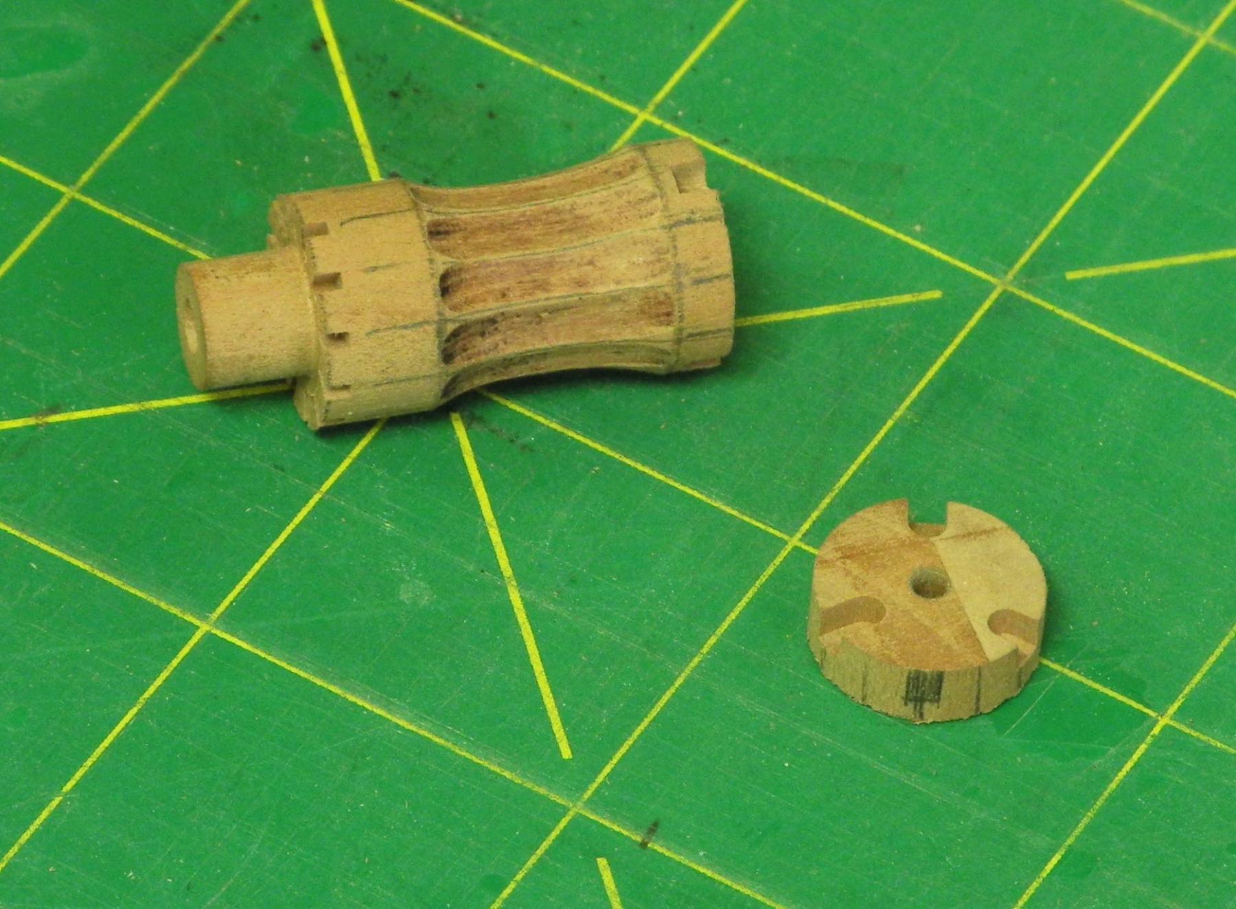
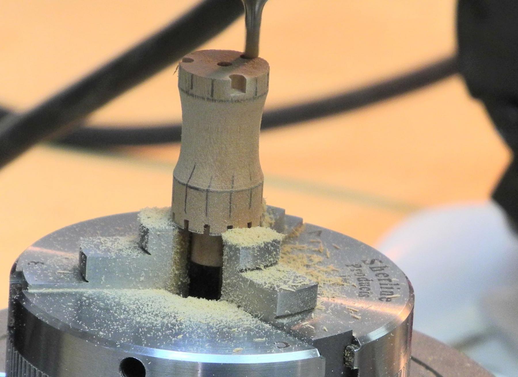
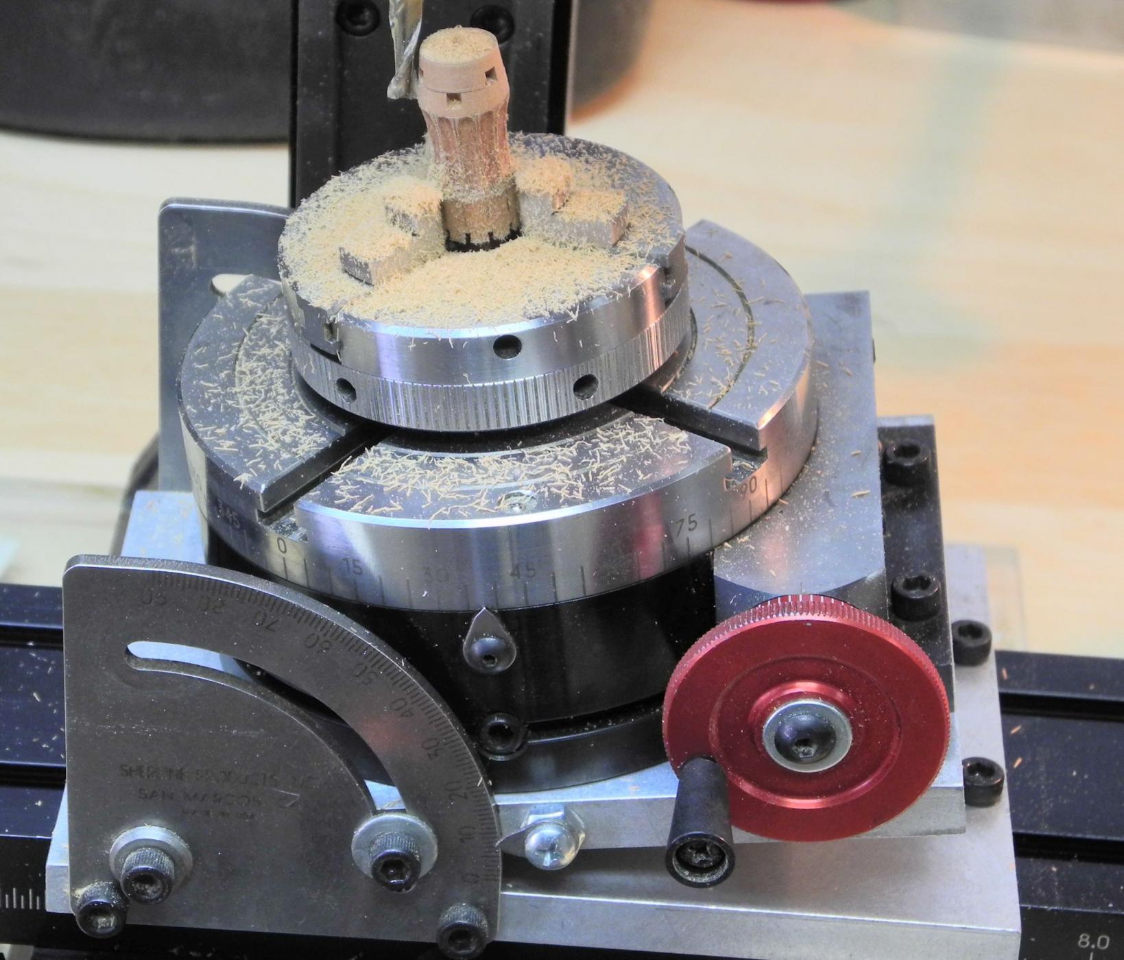
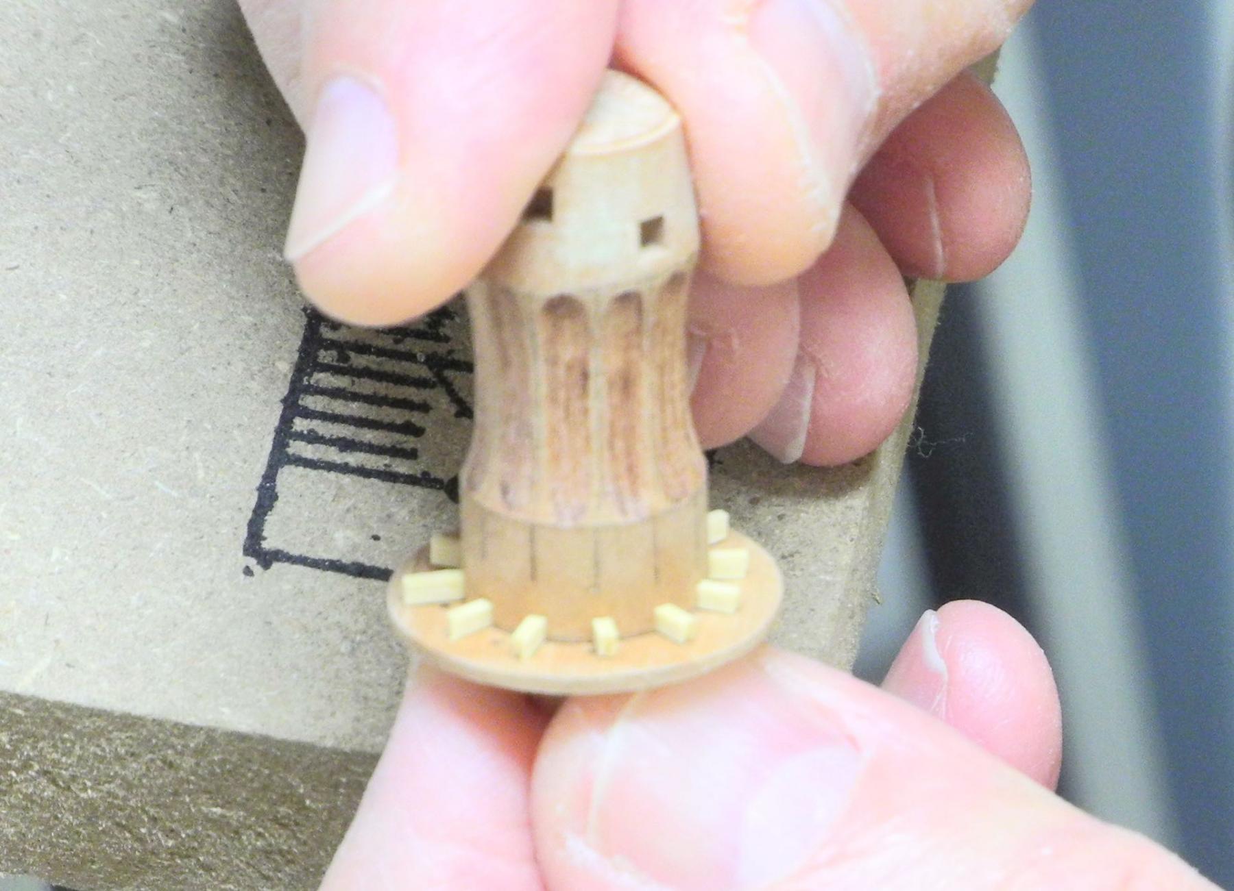
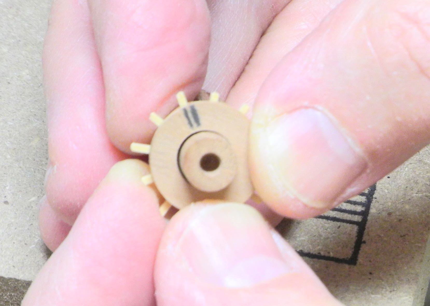
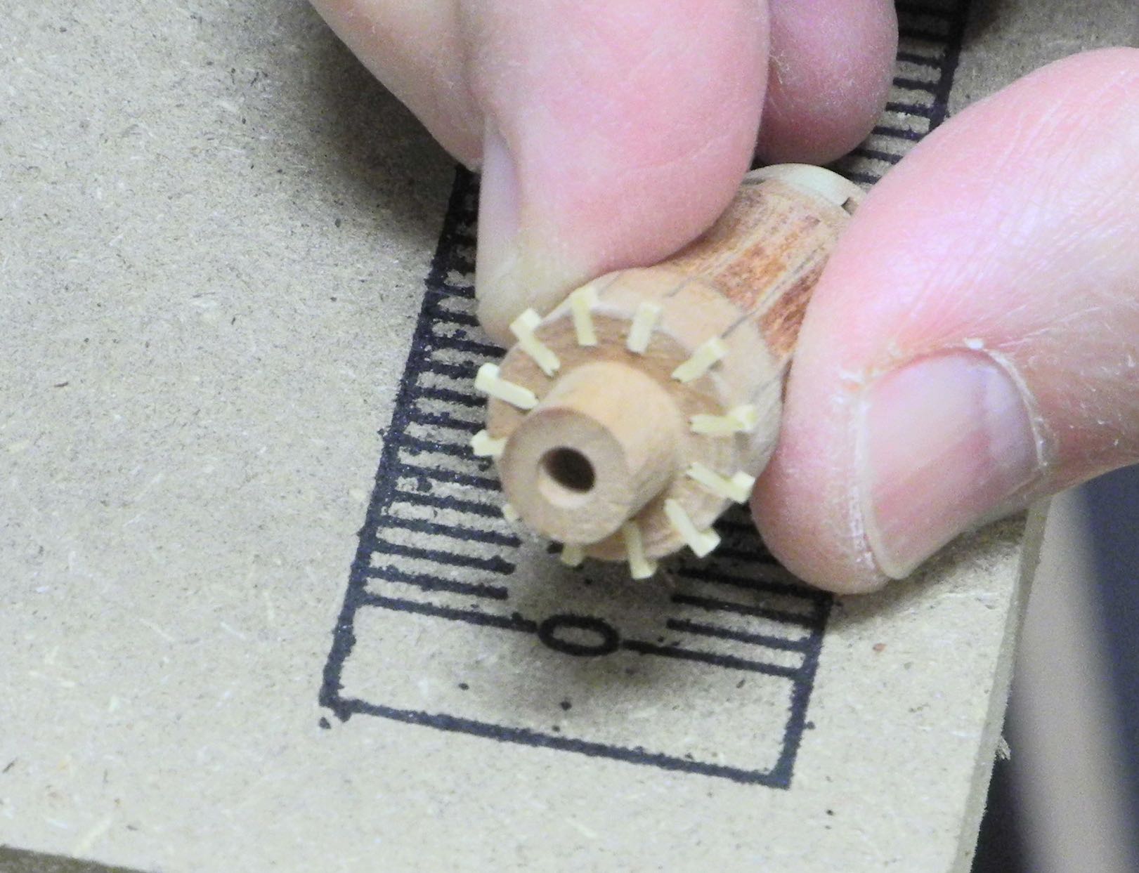
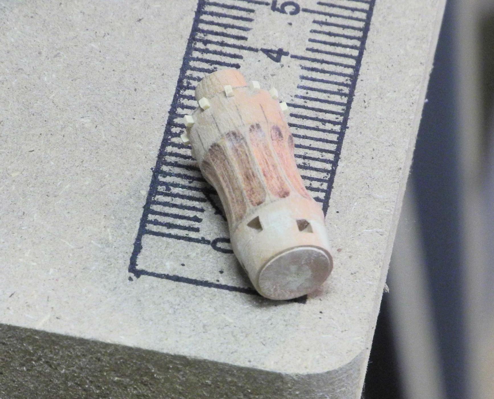
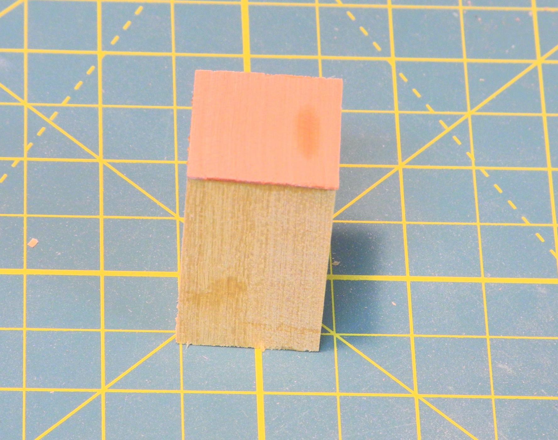
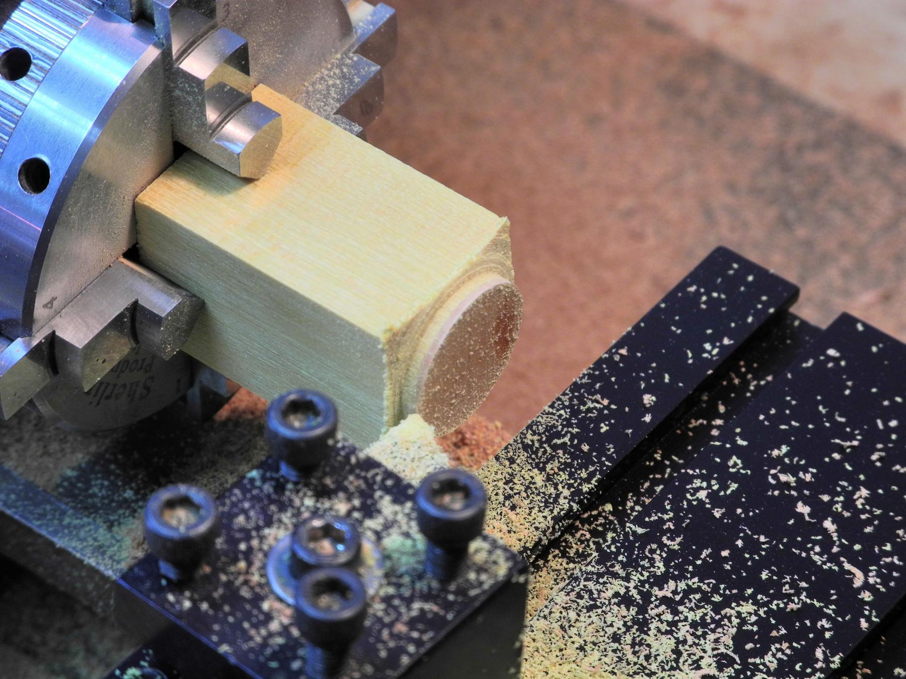
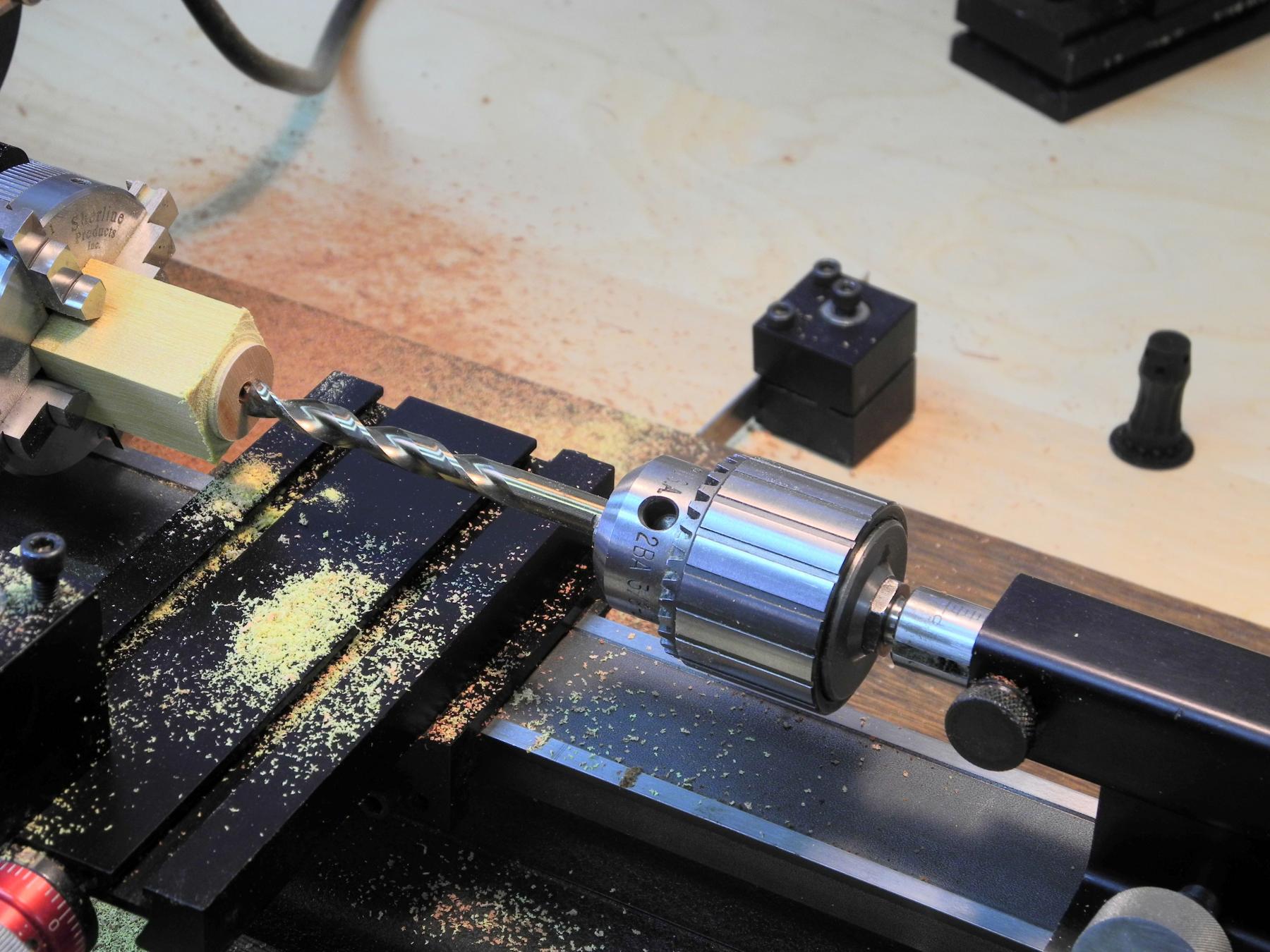
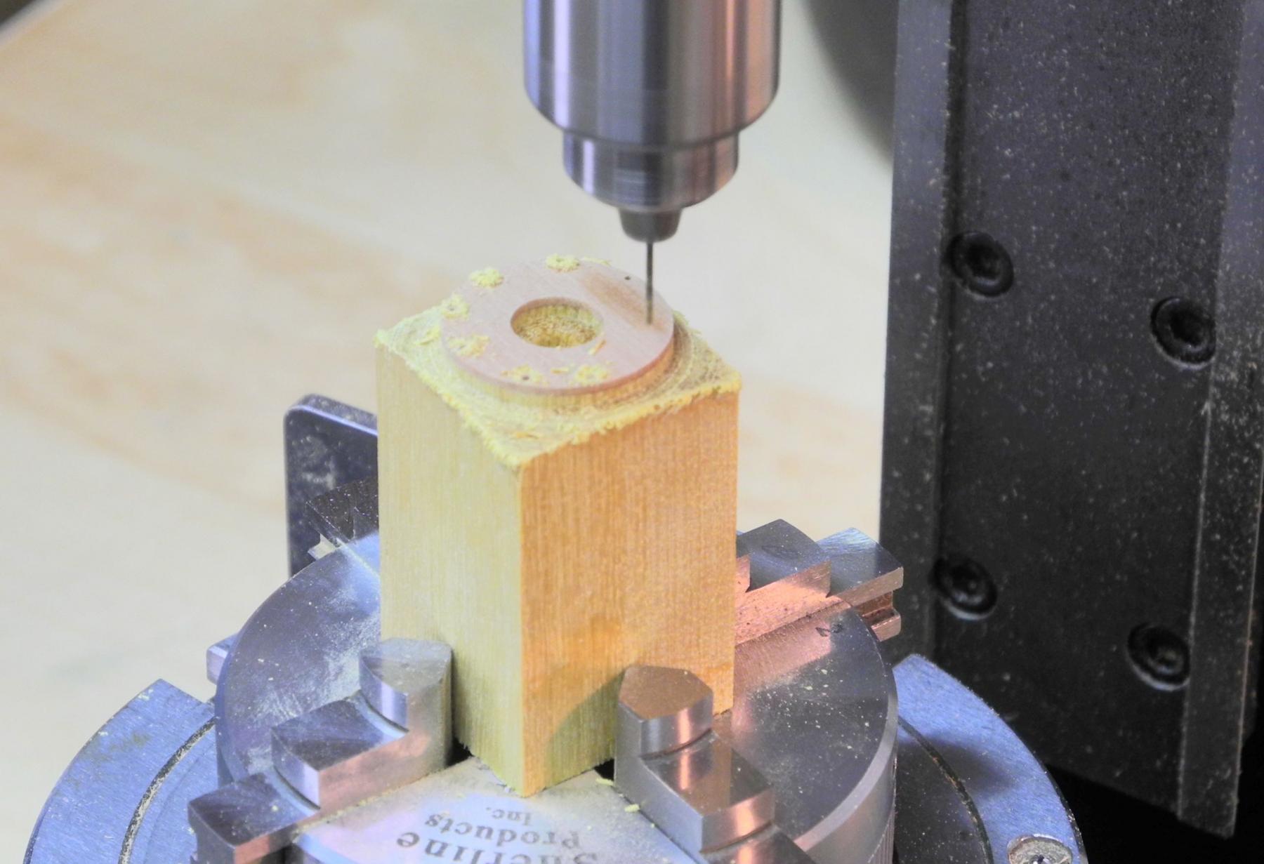
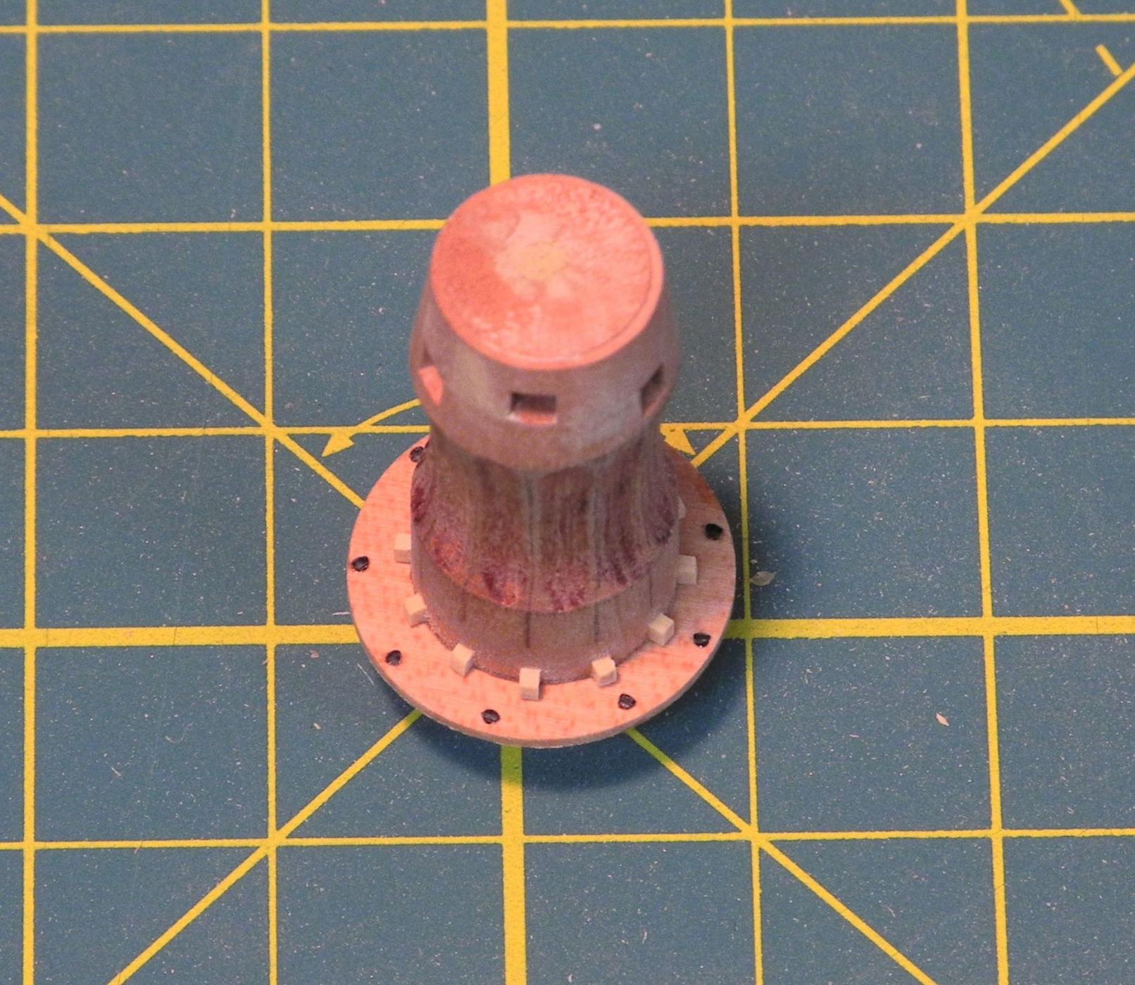
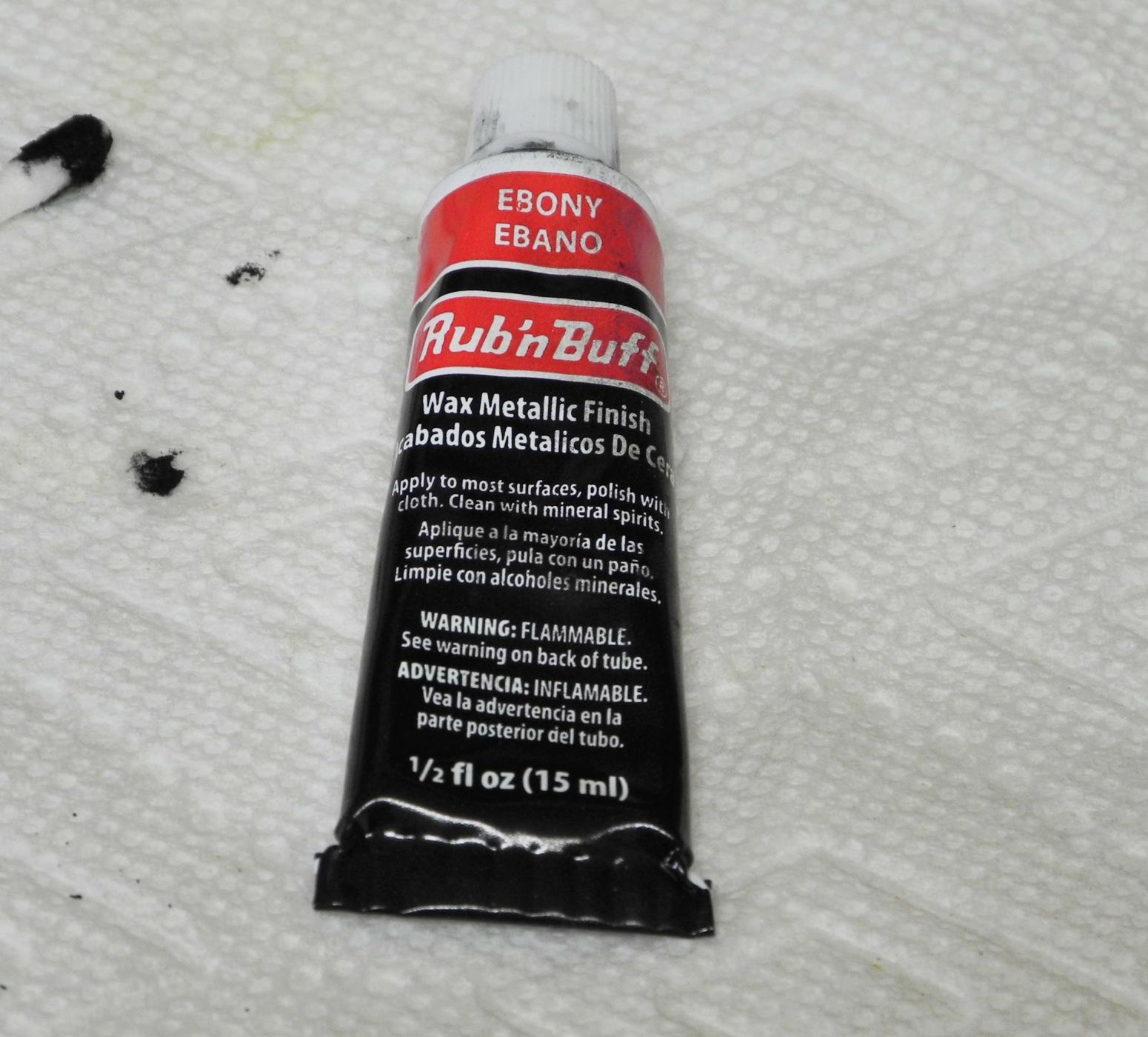
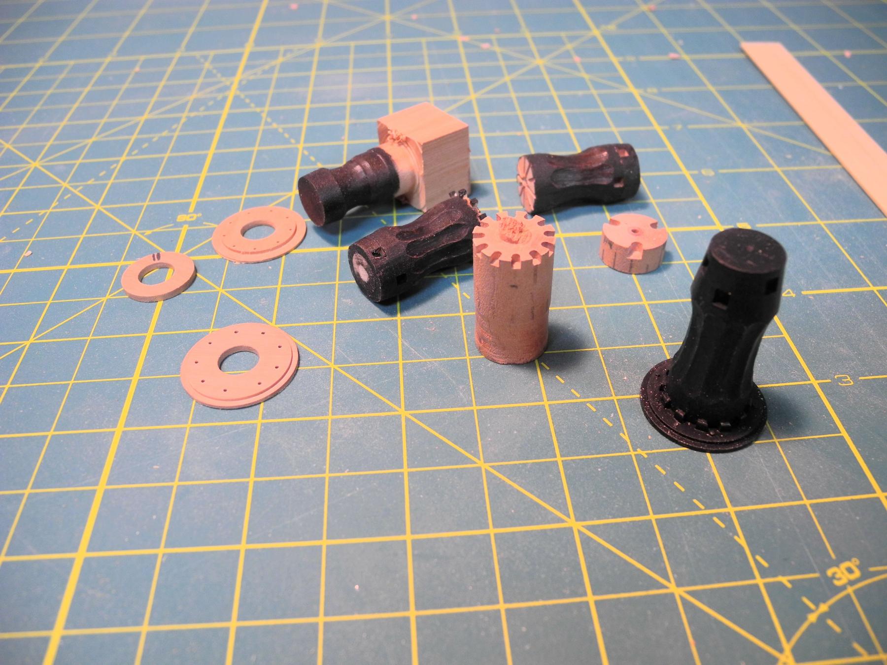
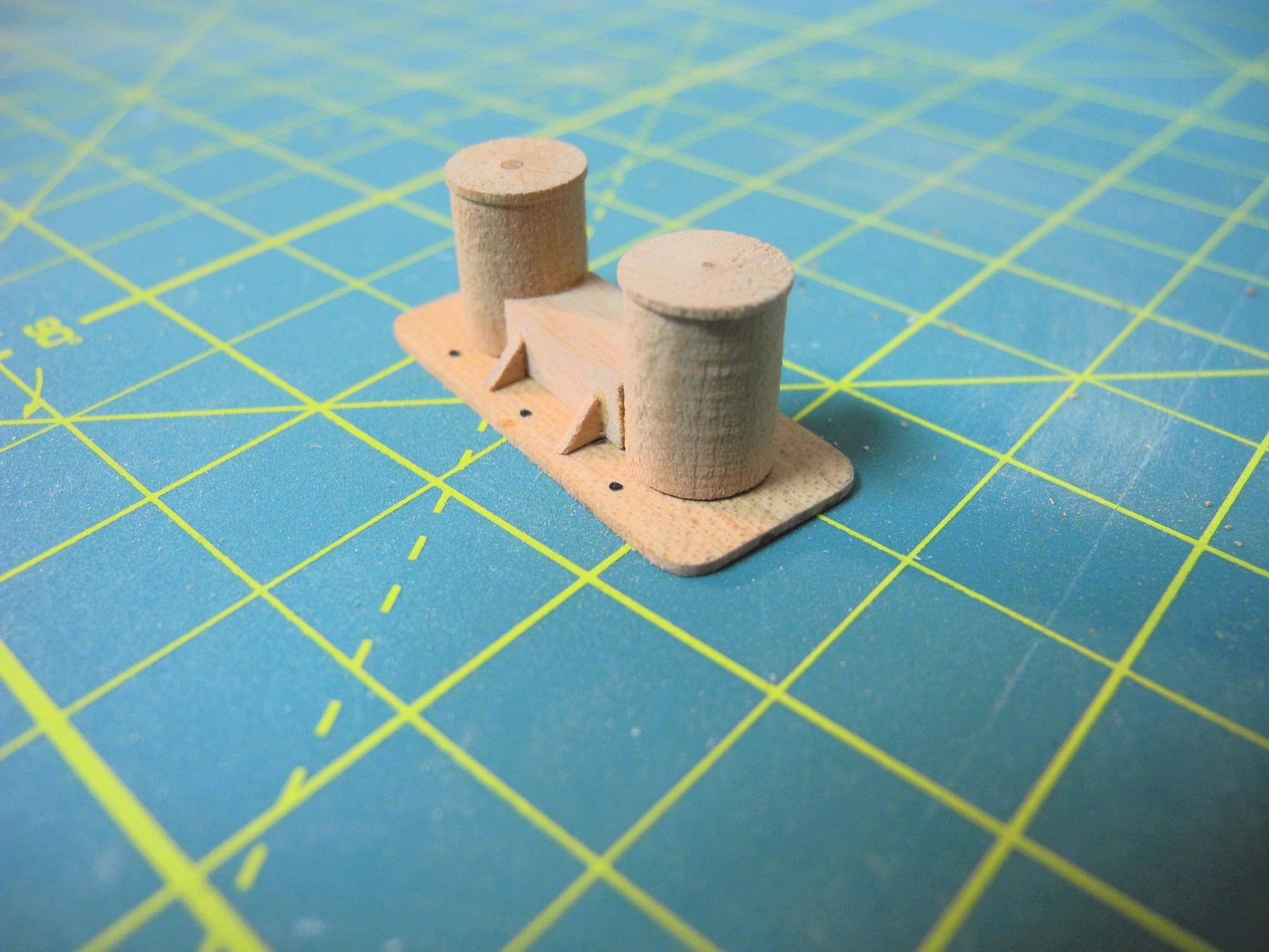
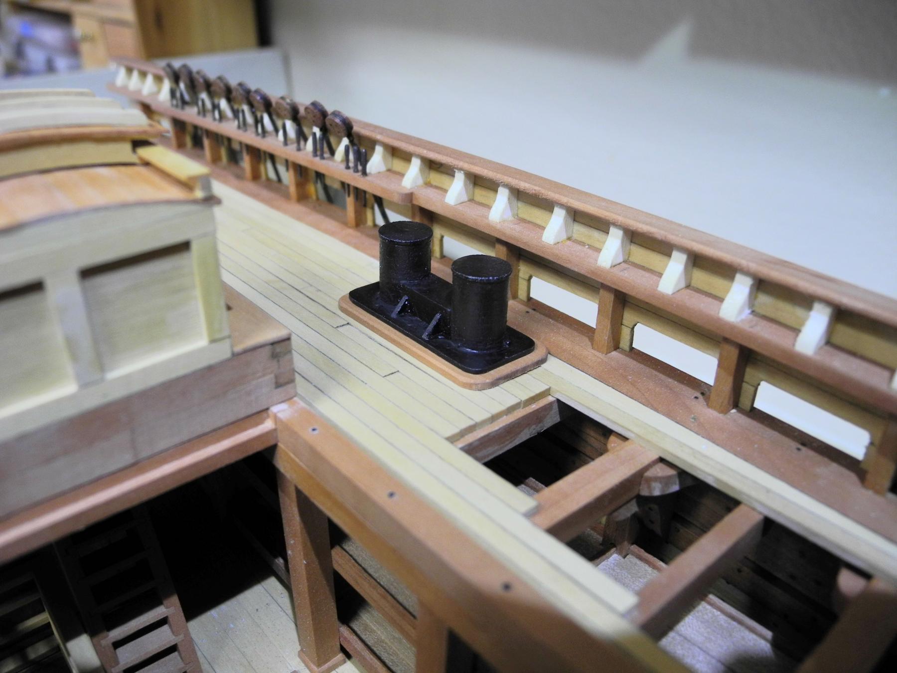
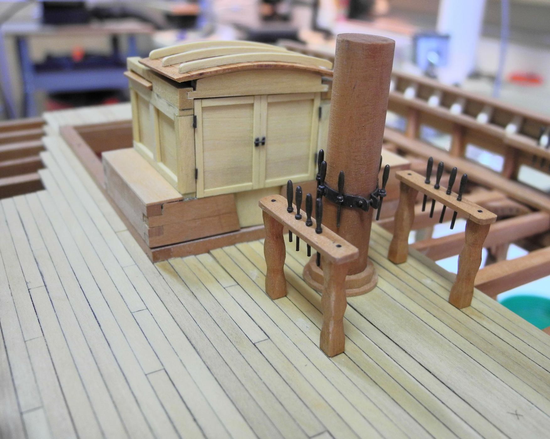
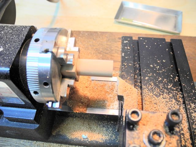
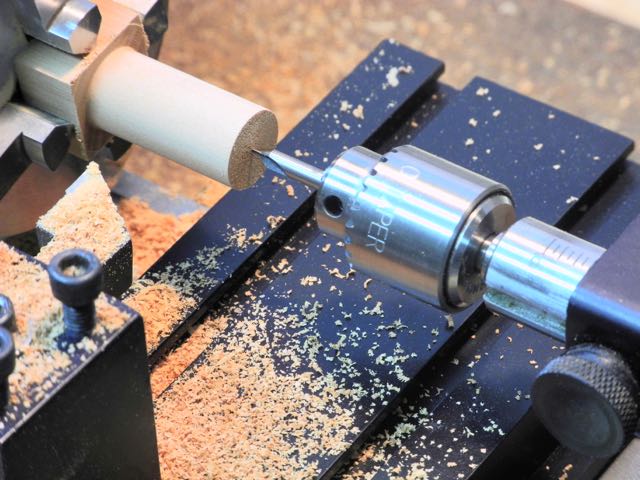
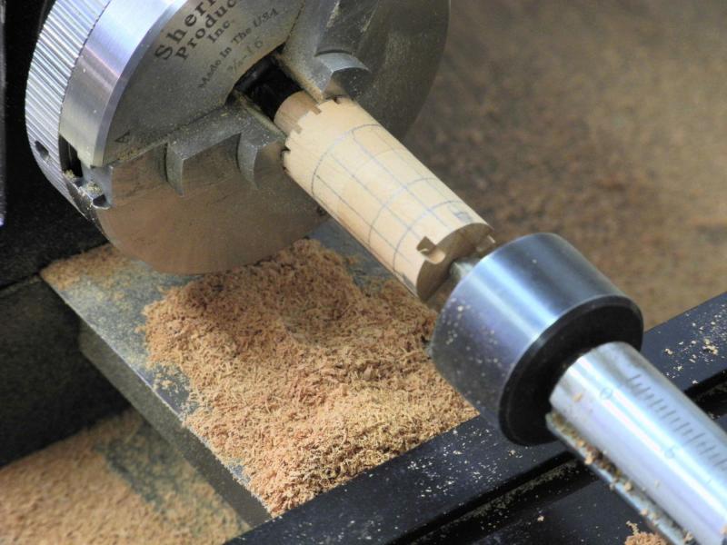
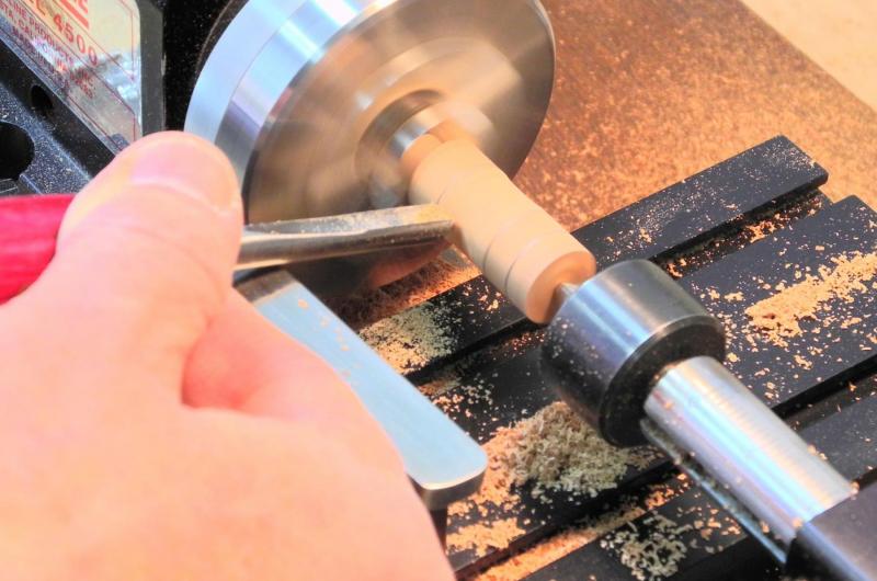
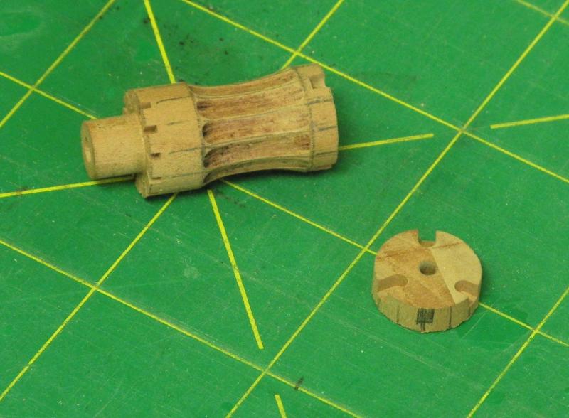
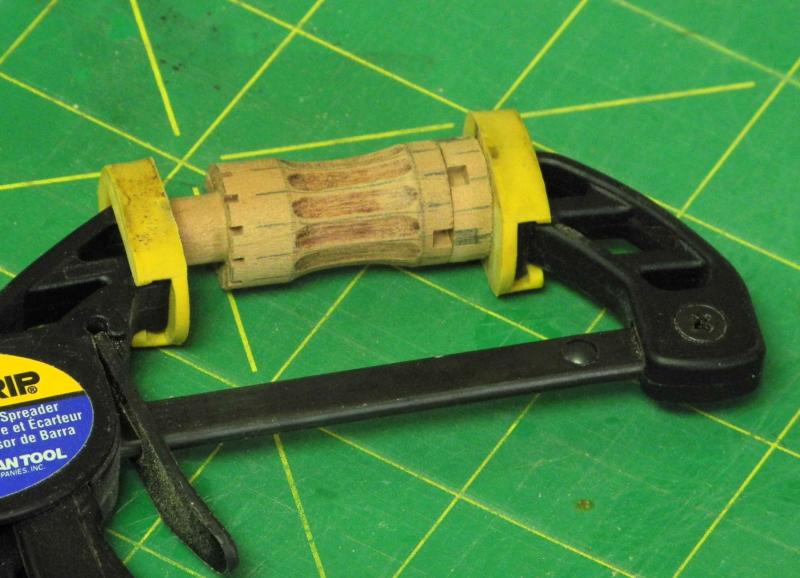
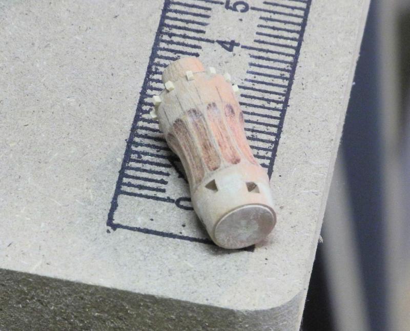
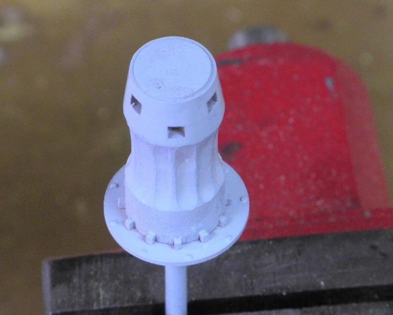
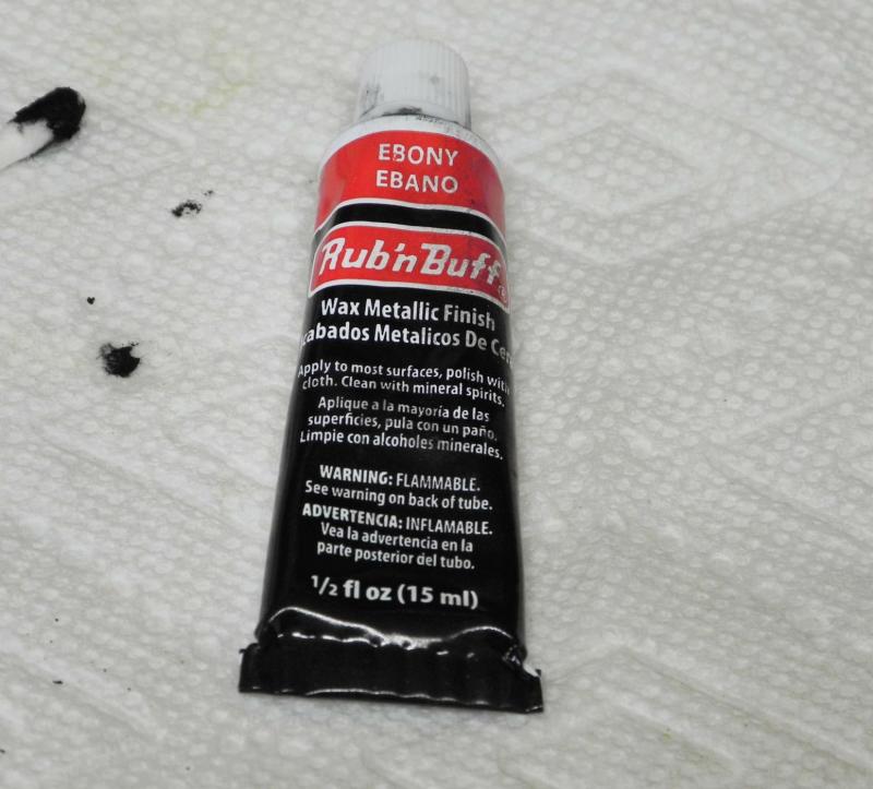
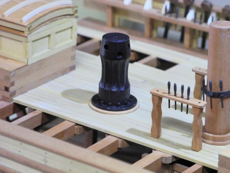
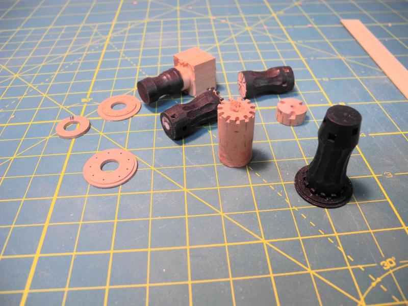
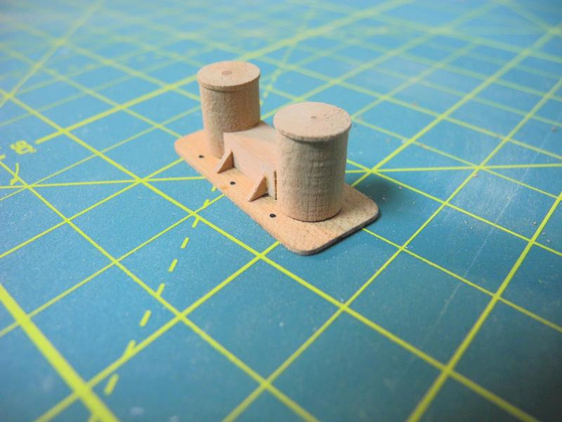
 Part 54 – Capstan and Bollards The capstan on the replica ship appears to be made from a metal, presumably cast iron, and is somewhat unusual when compared to capstans used on other ships. I decided to try to duplicate this design. I estimated the overall height of the capstan at 5 feet tall, which would put the capstan bars at chest height on a person of average height (5’6”) in the 19th century. Thinking through what needed to be accomplished to create the capstan, I decided to make it from wood and apply a finish that would simulate metal construction. The build process resulted in a lot of trial and error and restarts, but by the end a sequence of steps was developed which consisted of over 45 individual steps. The following text and photos represent the highlights of the process. A piece of square stock was reduced to a cylinder of .55” The cylinder was center-drilled and after mounting the workpiece on a rotary table on the milling machine, this hole was used to center the mill setup. The Y-axis was then locked in place. There will be 12 whelps on the capstan, so the borders of the whelps were marked every 30 degrees using the shaft of a small tool. 3/32 slots were then cut into the top of the capstan every 120 degrees. These slots would be the top bar slots of the capstan. Alignment marks which would be used to align the top and bottom slots were marked on the capstan. The capstan was remounted on the lathe and the bottom of the capstan workpiece was reduced to 7/32 beyond the bottom limit of the actual capstan. This small ‘tab’ would be used to hold the workpiece in later steps. The workpiece was remounted on the mill, and .041 slots were cut every 30 degrees. These slots would be used to position the pawl stops on the base of the capstan. The workpiece was remounted on the lathe, and three separate lines were drawn around the workpiece. The line nearest the top of the capstan was used to designate where the top would be parted off, and the other two lines designated the top and bottom boundaries of the whelps. A wood tool rest was mounted on the lathe, and miniature wood lathe tools were used to shape the concave profile of the whelps. A round diamond ball on a rotary tool was used to shape the concave indentation in the individual whelp positions, while holding the workpiece by hand (I wasn’t able to determine how this could be accomplished on one of my machine tools). The workpiece was remounted on the lathe and the top of the workpiece was then parted off. The workpiece was moved to the rotary table on the mill, and the second set of slots was milled in the top of the workpiece. The top was glued to the workpiece, using the alignment marks to position the slots. After the glued pieces were set, the workpiece was mounted on the rotary table and the tilting table was set at 8 degrees. The side of a milling bit was then used to mill the slant into the top of the capstan. The pawl stops consist of very small pieces of .041 x .0625 stock. These were glued into the slots previously cut into the bottom of the capstan. A scrap piece with a hole that would fit over the tab in the bottom of the capstan was used to ensure that these small pieces were level with the base. After the glue had set on these pawl stops, another scrap piece was used as a template to reduce the stops to the correct length (1/16”). The overall shape of the capstan was now completed. The base of the capstan consists of two pieces – a metal disk mounted on a wood base. Two pieces of .035 stock were glued to sacrificial pieces using Ambroid glue. These workpieces were then turned to the appropriate diameter, and a 7/32 hole was center drilled in each, to allow the piece to mount over the bottom tab that was previously shaped on the capstan. This helped in centering the bottom plates on the capstan. The piece representing the metal plate was then drilled for mounting bolts every 40 degrees. After separating the plates from the sacrificial pieces by soaking in acetone, black monofilament was used to simulate the mounting bolts in the ‘metal’ plate, and the ‘metal’ plate was attached to the capstan. The capstan was primed, then painted with black acrylic artist’s paint, and then was finished with ebony Rub’n’Buff to provide a metal-like finish. The capstan was then mounted on its wooden base, and the bottom tab was ground off. The following photo shows the finished capstan in place on Dunbrody. This was quite a learning process, illustrated by all of the rejected pieces. By comparison, the bollards were fairly simple to make. So work on Dunbrody is now essentially completed. I may replace the current base with a new one, but that will be left for some time in the future. Originally I had thought to mount Dunbrody on a replica of launching ways, but this plan has been shelved. I’ll post a set of photos of the finished Dunbrody in the near future. Thanks to all who have followed this build, and thanks for the ‘Likes’ and all of the great comments. Your encouragement has helped to keep me focused, and knowing I would be posting progress made me re-do all of those things which might otherwise have been ‘good enough’.


- 649 replies
-
- 25
-

-
- dunbrody
- famine ship
- (and 2 more)
-
Looking good Patrick. I do like the silver bottom. The waterline stripe will really set things off.
-
Thanks so much, Ed. Working on Dunbrody has given me an even greater appreciation of what you've done on Young America.
- 649 replies
-
- 5
-
-
- dunbrody
- famine ship
- (and 2 more)
-
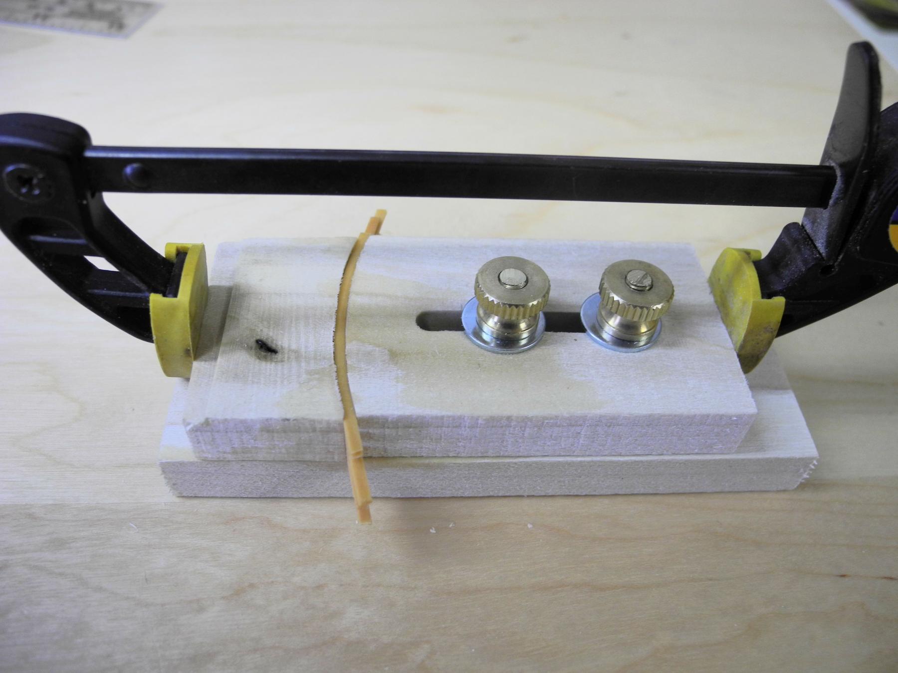
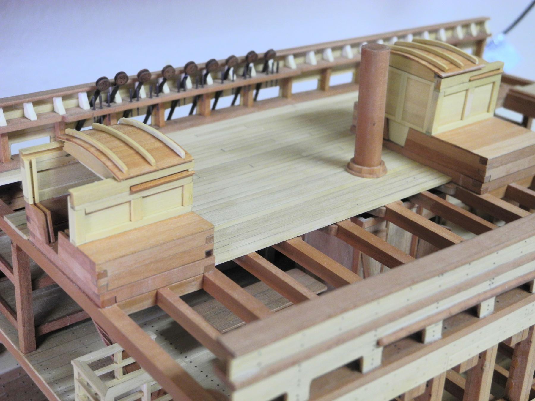
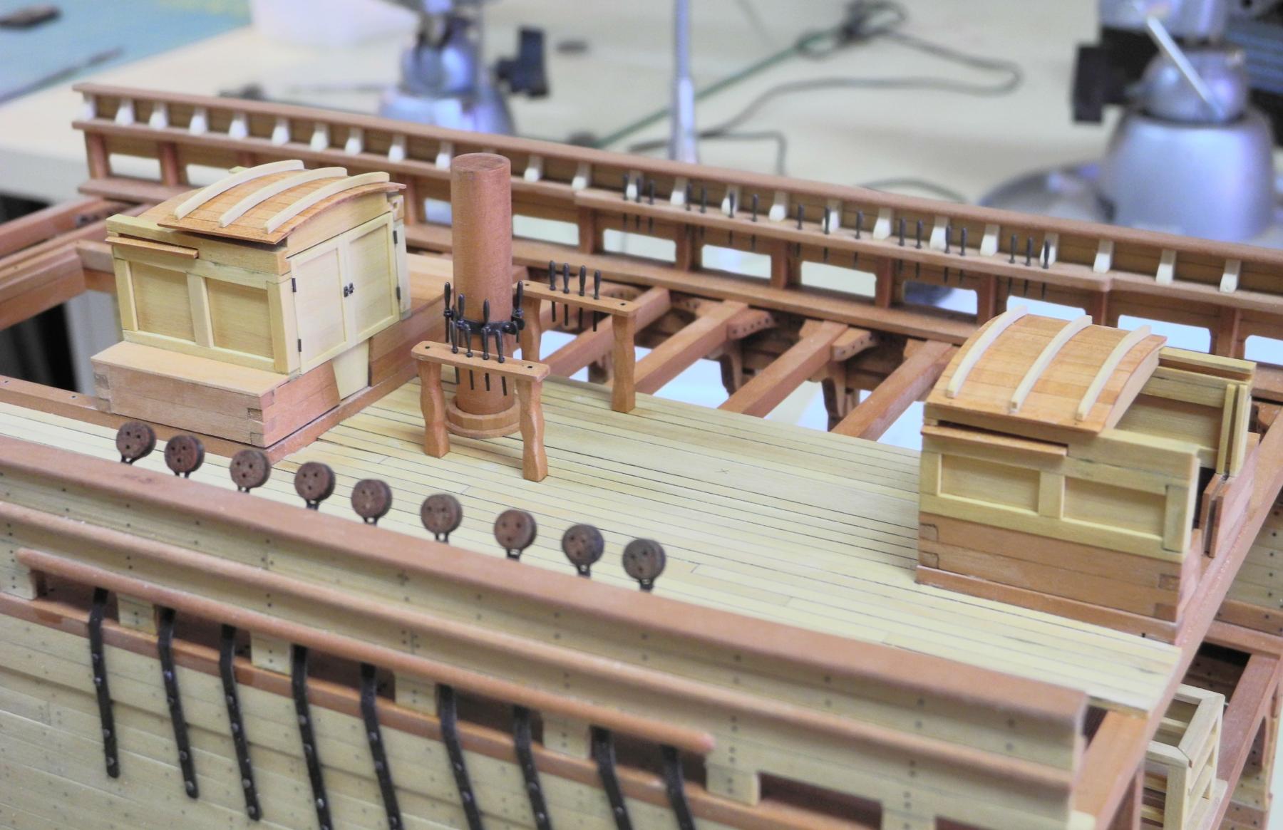
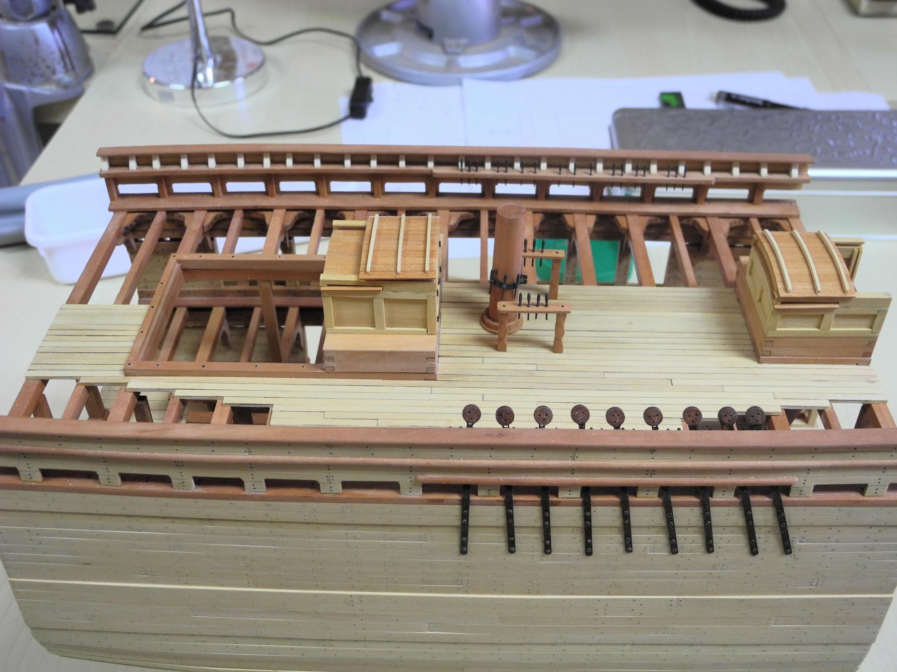
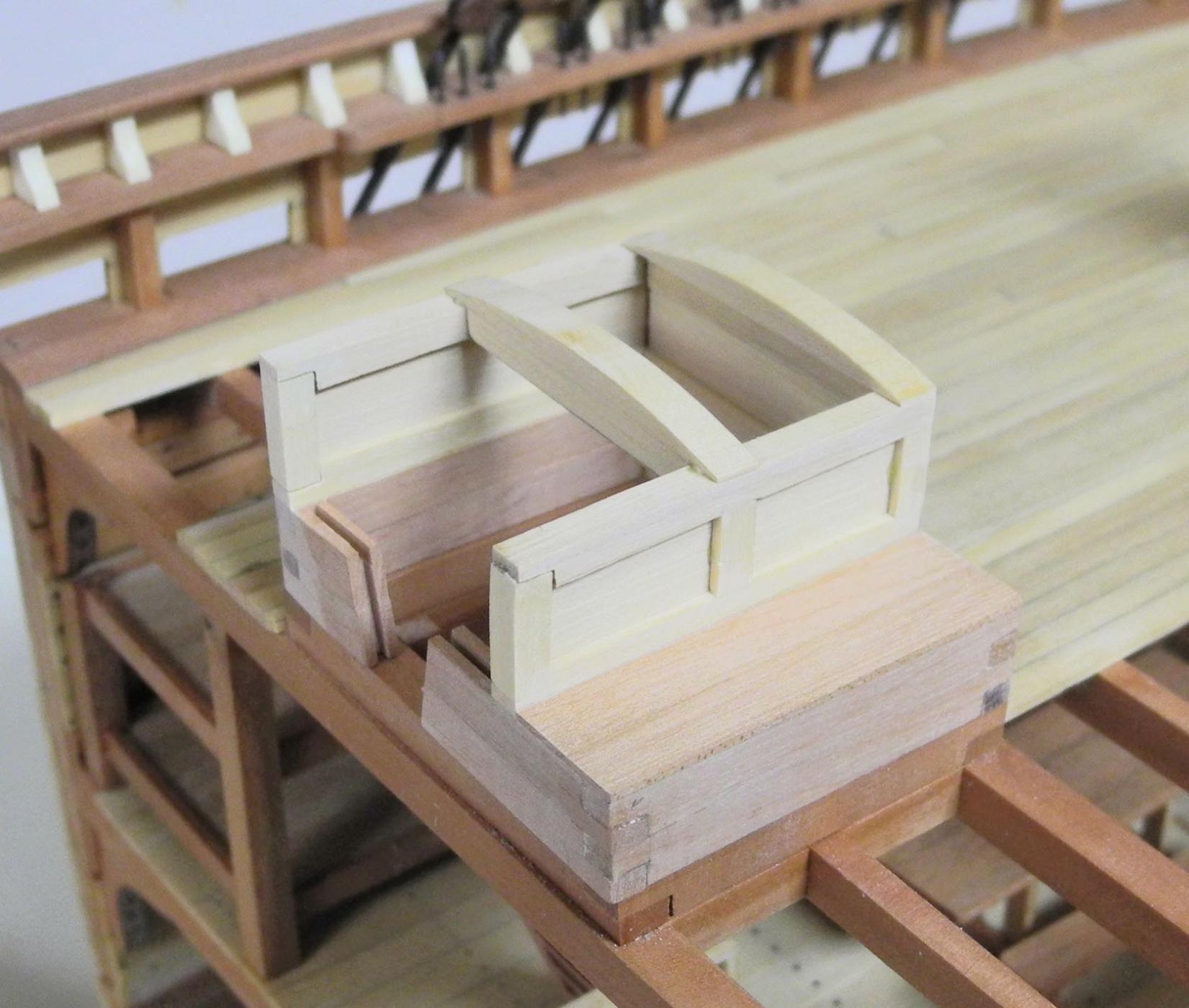
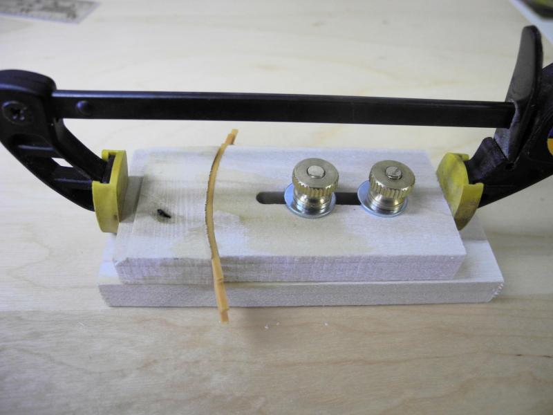
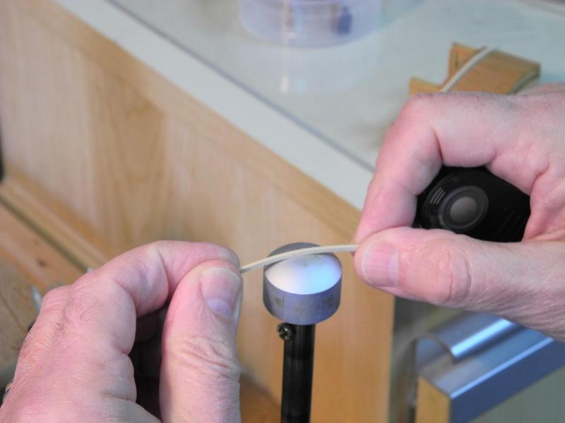
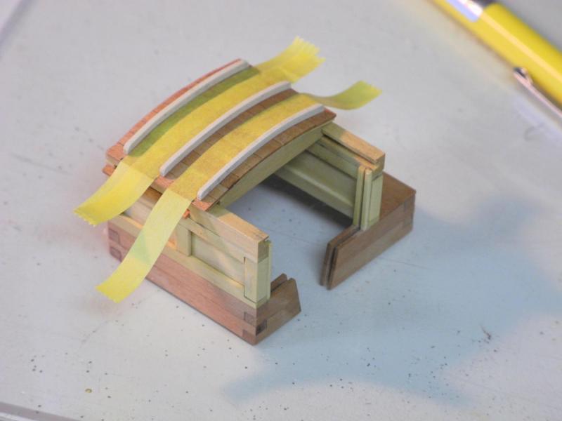
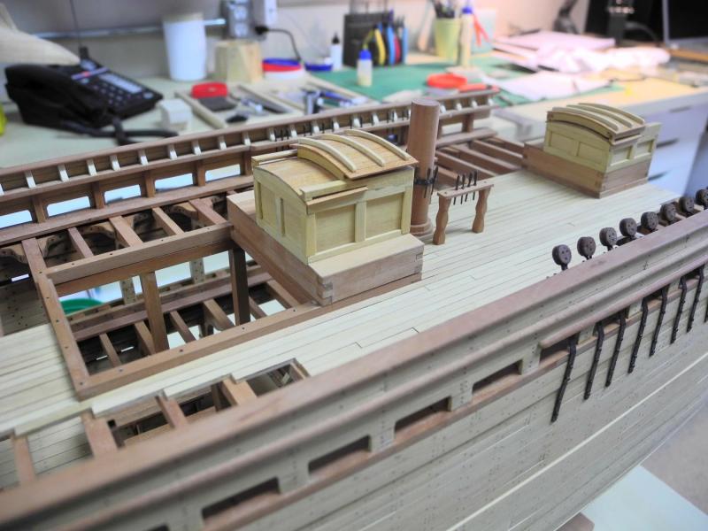
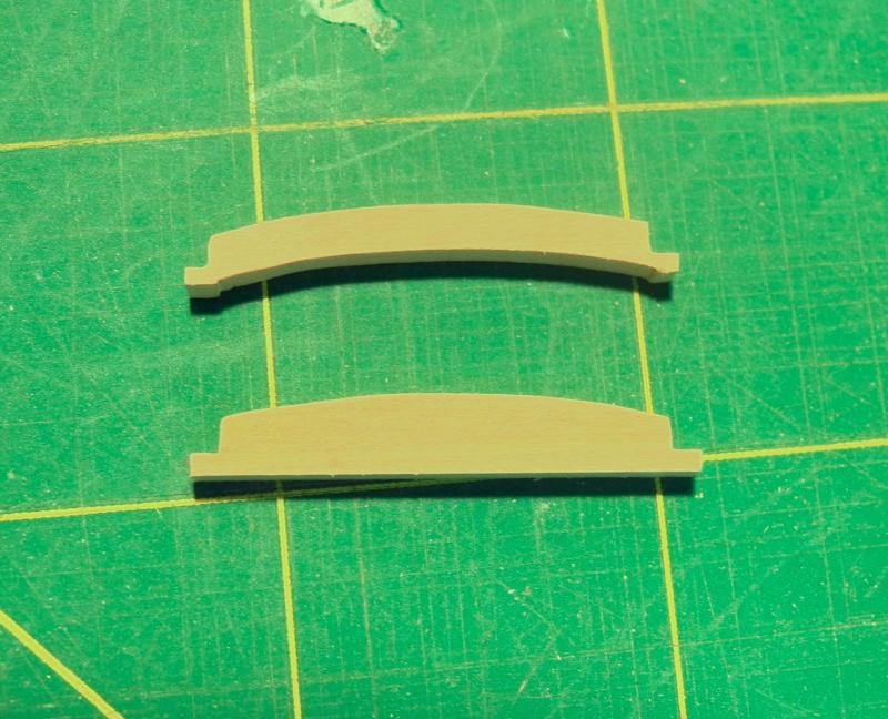
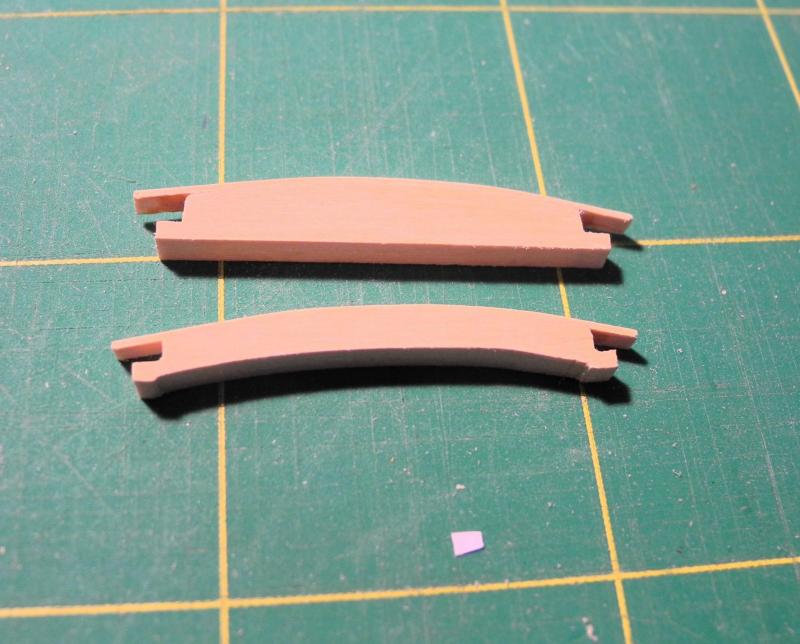
Part 54 – Companions, continued The cross braces on the sliding roof obviously secure the roof planking. On the model, these braces are 1/16” (.0625) tall and .040 thick. I decided to bend these pieces to match the curve of the roof, rather than trying to cut them to shape. I used the jig shown in the following photo to bend the pieces after soaking them in boiling water. Since the bending was along the edges, the pieces had a tendency to try to spring back even after leaving them in the jig overnight, so heat was used to bend them to the final shape, as shown in the following photo. The location of the cross pieces was then measured and marked with masking tape. When the cross pieces were glued in place they still needed a finish of wipe-on poly applied. The simulated hardware for the main companion was made from pieces of blackened copper wire and was glued to the companion using CA glue. The Spider Band and Fife Rails had been temporarily placed prior to this step, and they along with the Companions were permanently installed after preparation of the companions was completed. The following photos show the current state of the model. I hope to complete the remaining work through the weekend. Thanks everyone!


- 649 replies
-
- 28
-
-
- dunbrody
- famine ship
- (and 2 more)
-
Thanks Bob and Neal. Carl - the cross pieces are 1/16 (.0625) tall, but only .040 thick, and they need to be bent along the thick edge, so I referred to that as edge-bending. This is more difficult than bending along the wide part, since the pieces want to spring back. (See my next post - coming shortly)
- 649 replies
-
- 5
-
-
- dunbrody
- famine ship
- (and 2 more)
-
Thank you Albert Thanks Carl. Yes, I'll be adding the cross pieces. I've had them bending overnight, but since they're being edge-bent we'll have to see if they hold the curve.
- 649 replies
-
- 5
-
-
- dunbrody
- famine ship
- (and 2 more)
-
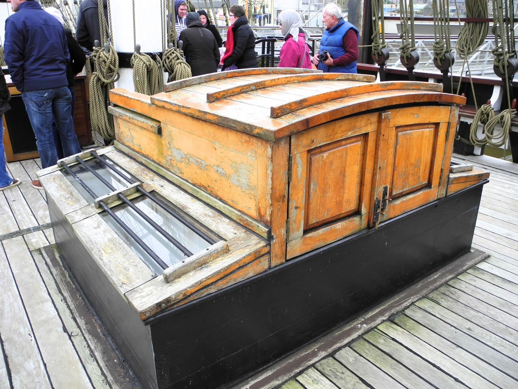
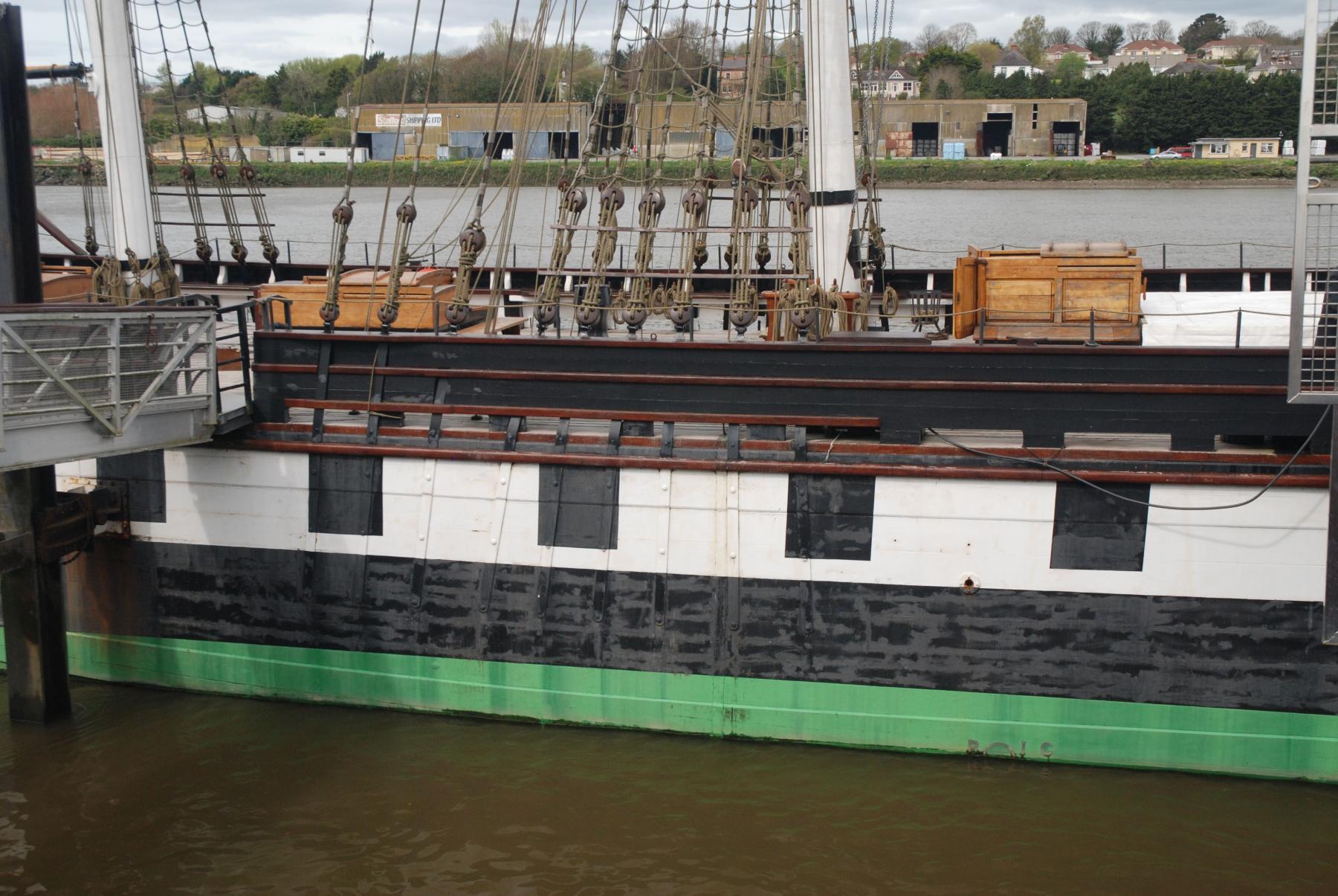
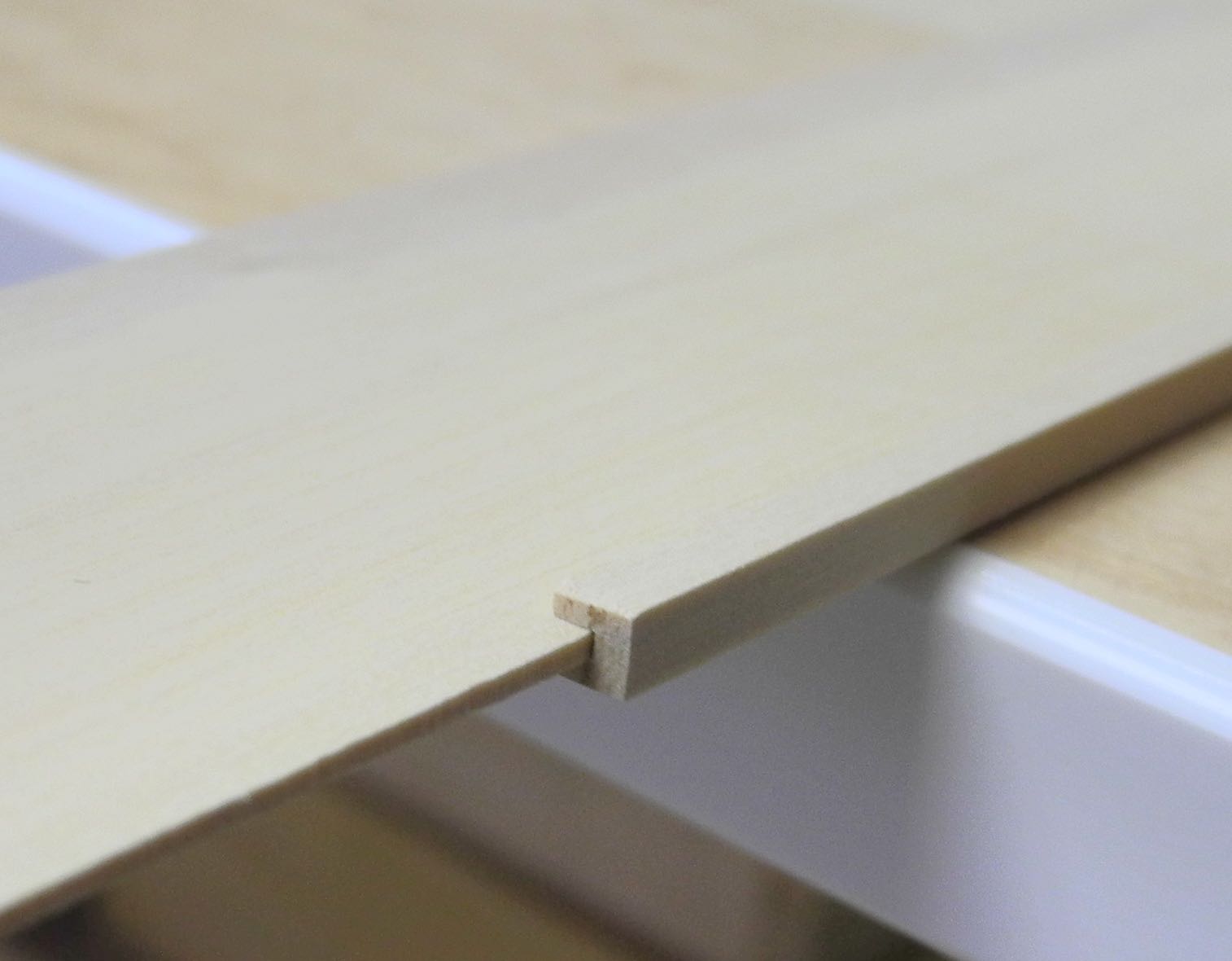
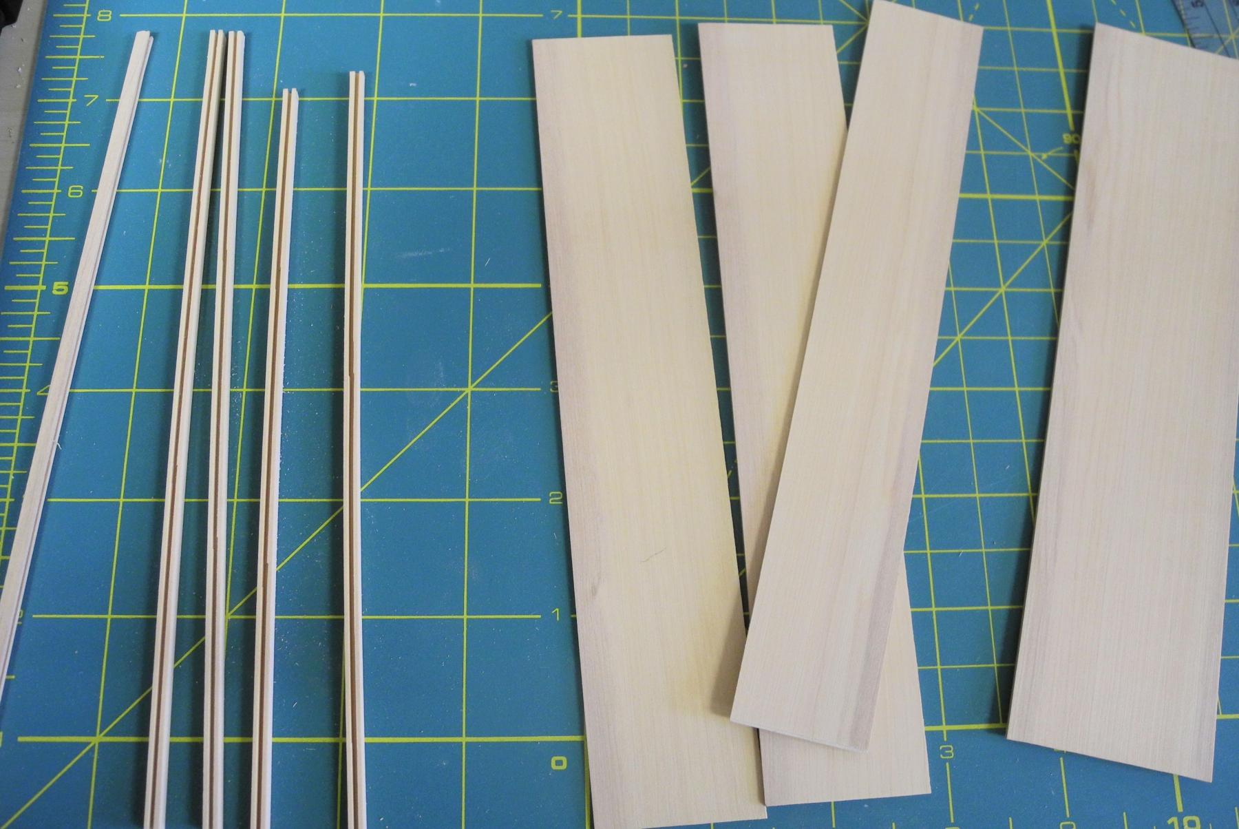
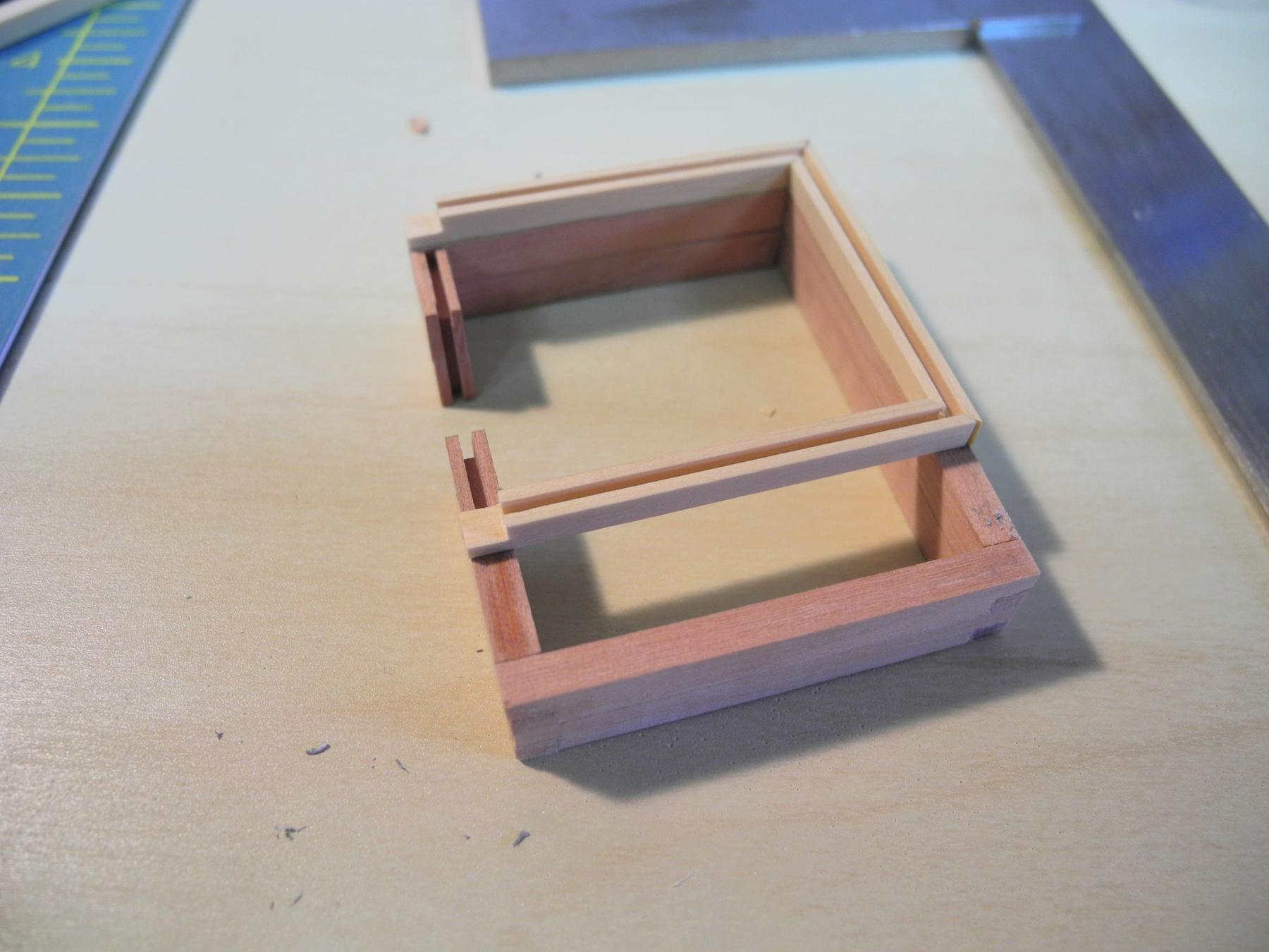
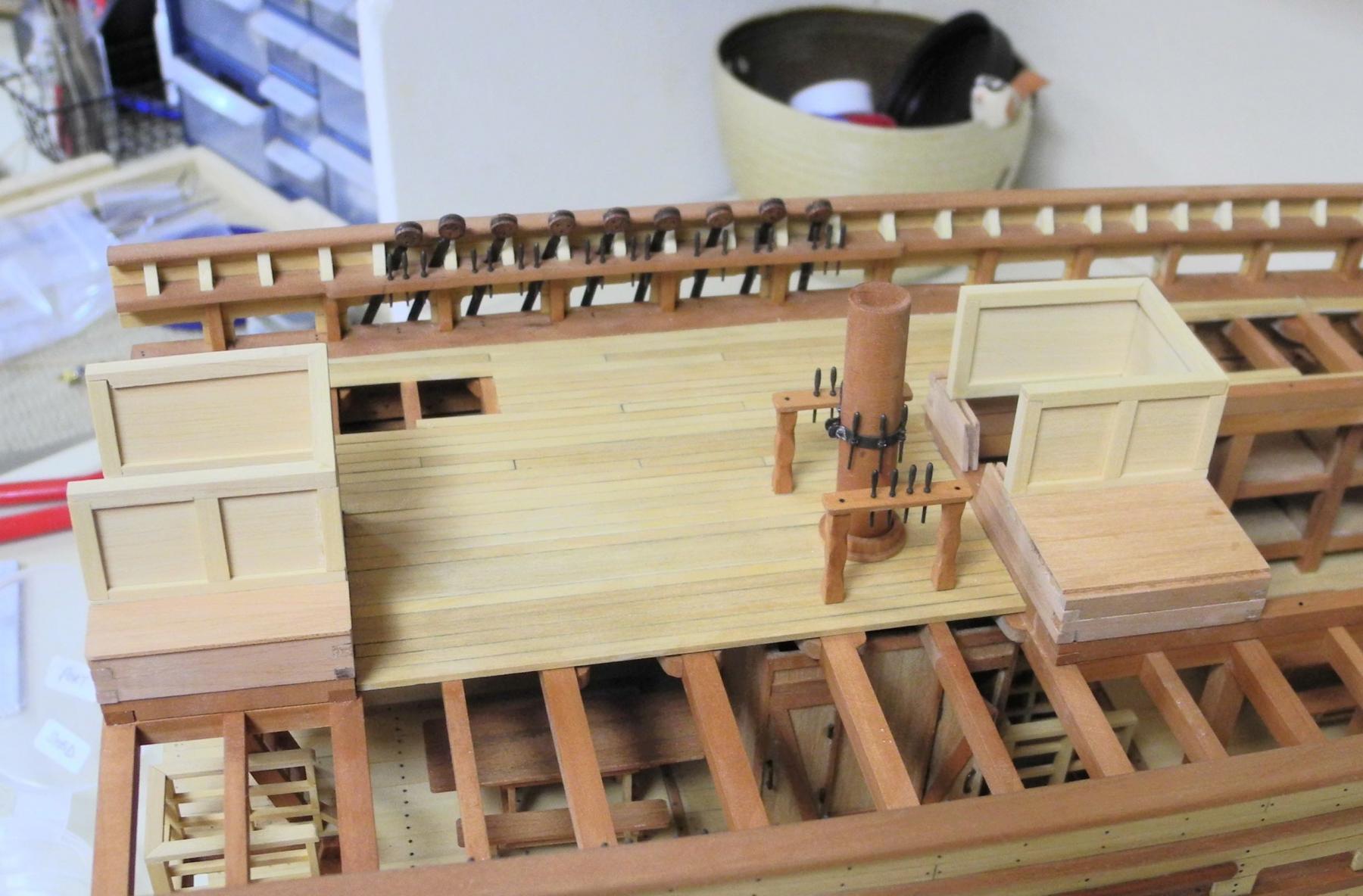
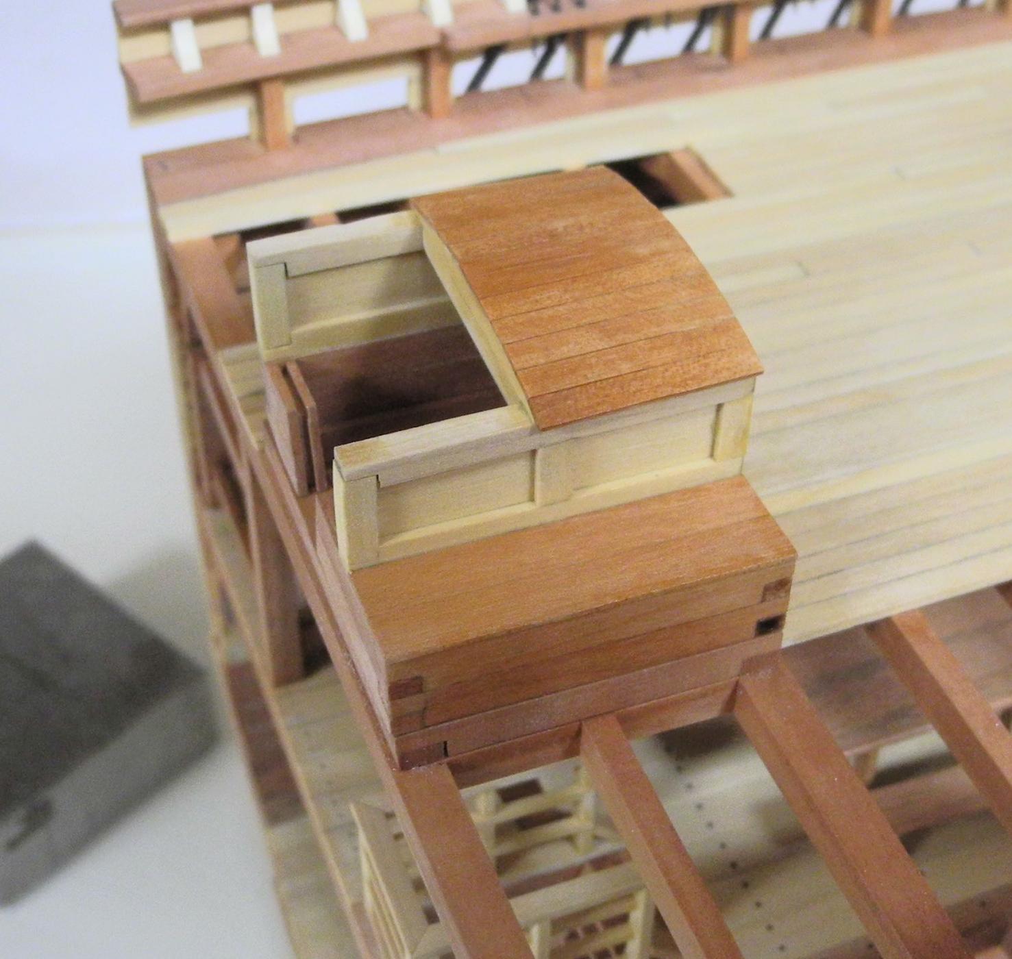
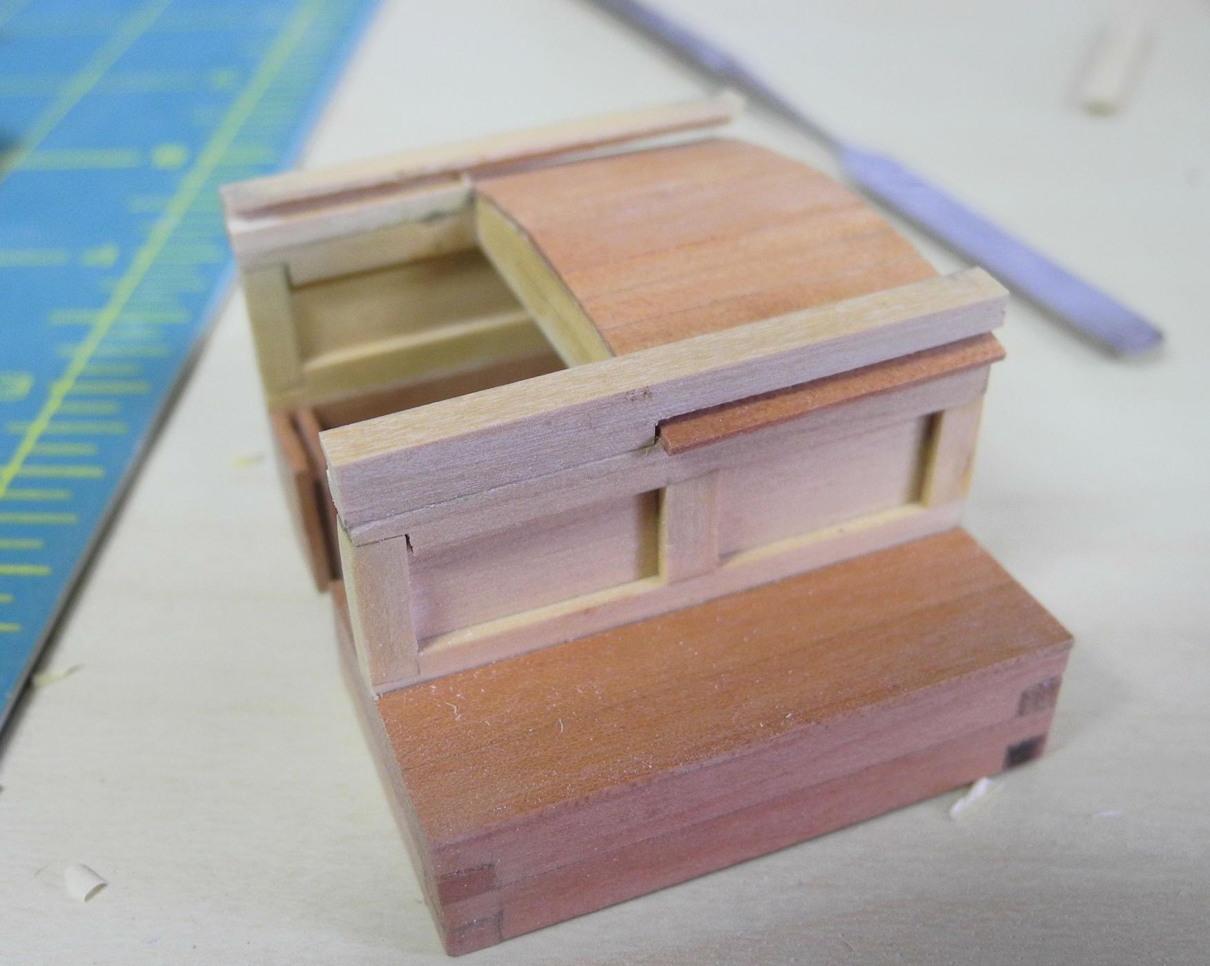
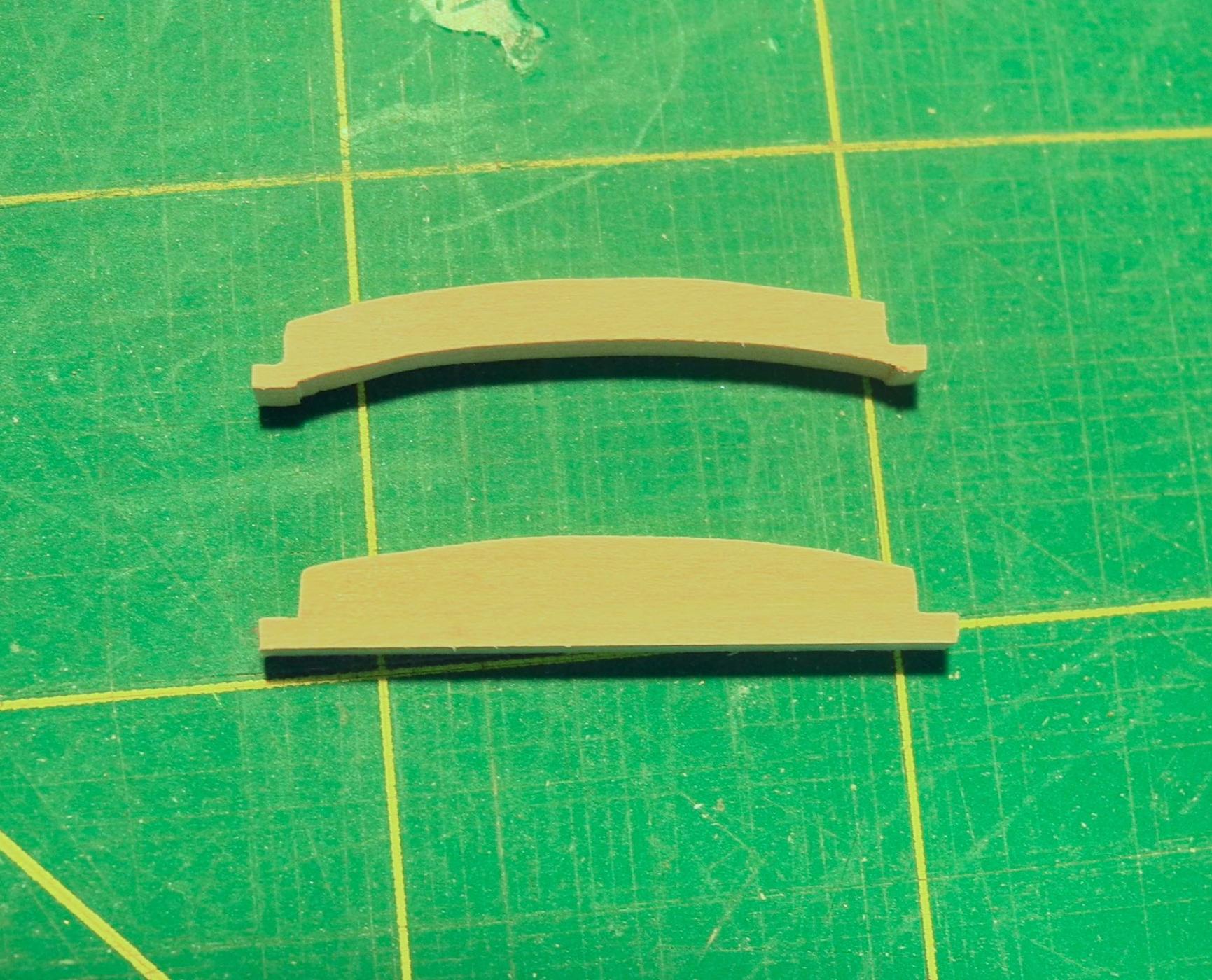
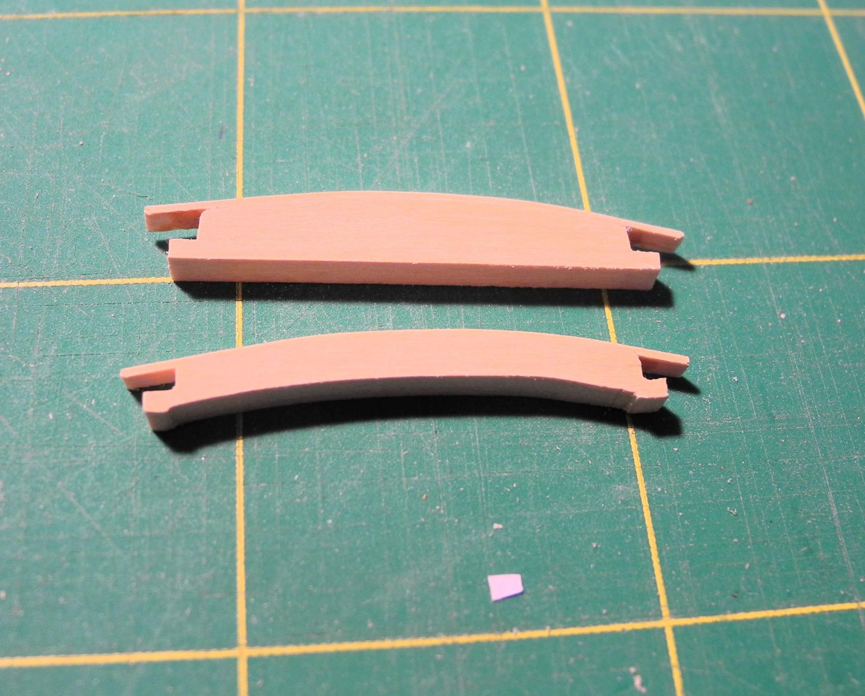
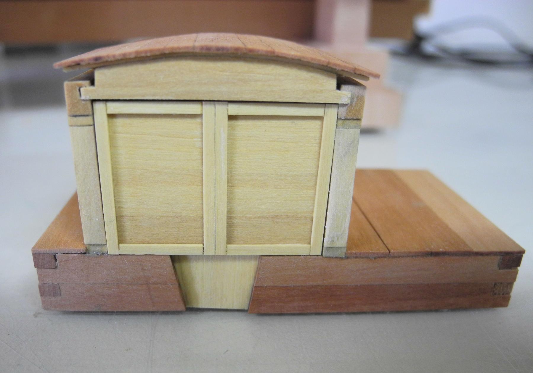
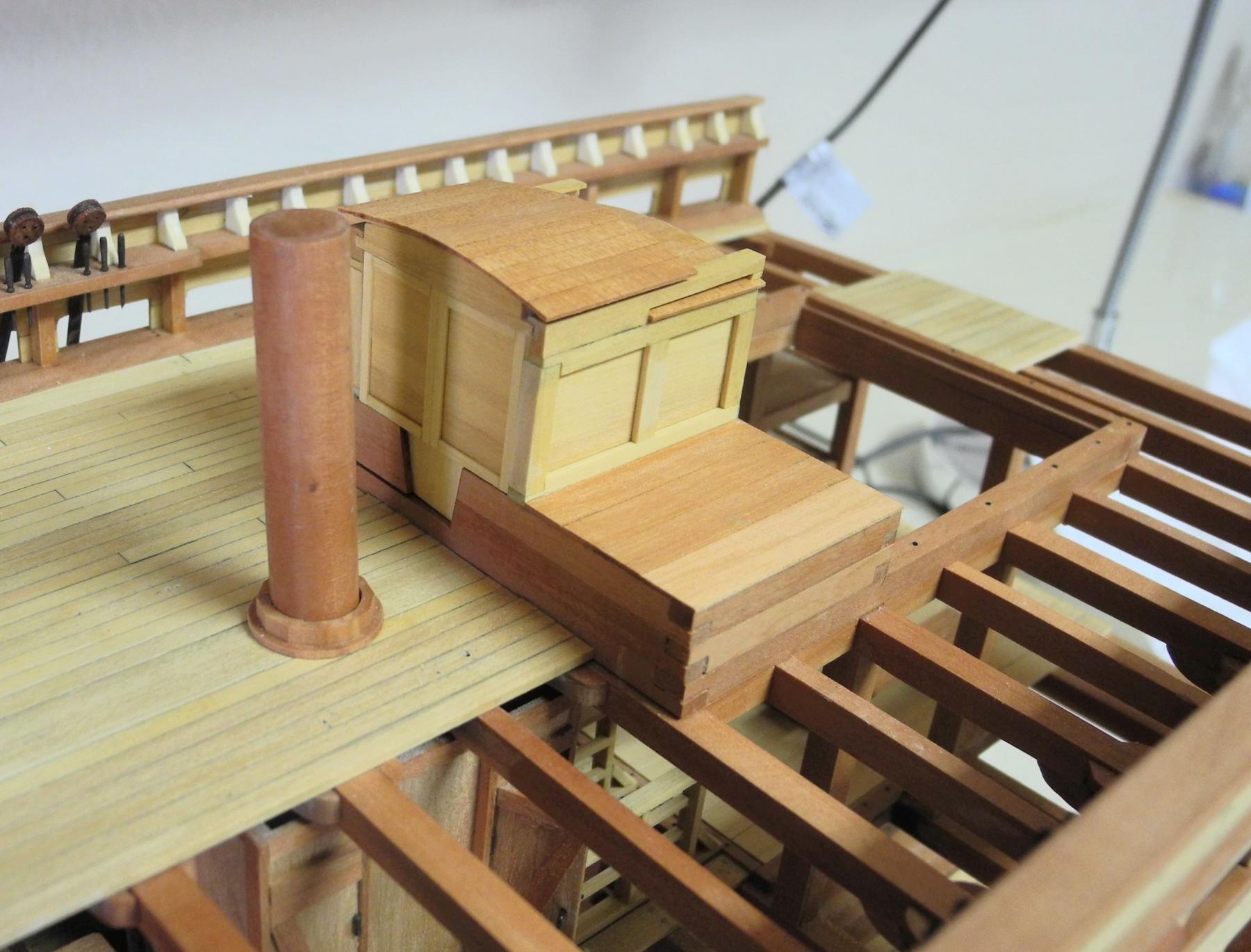
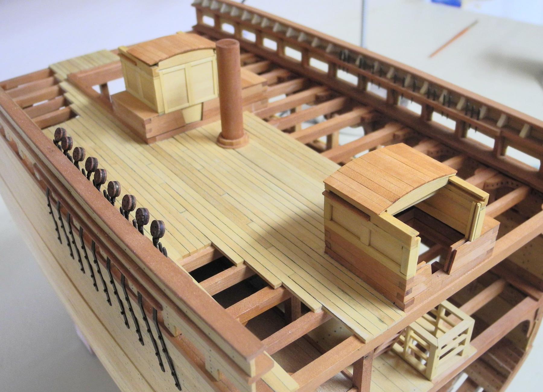
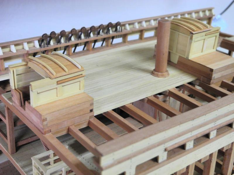
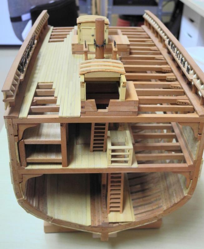
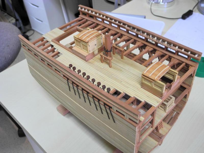
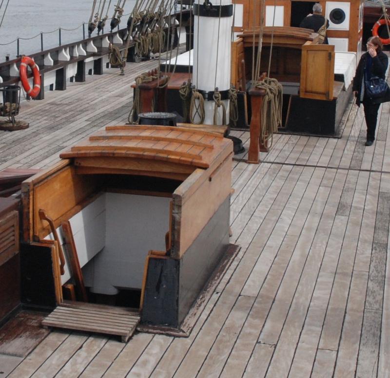
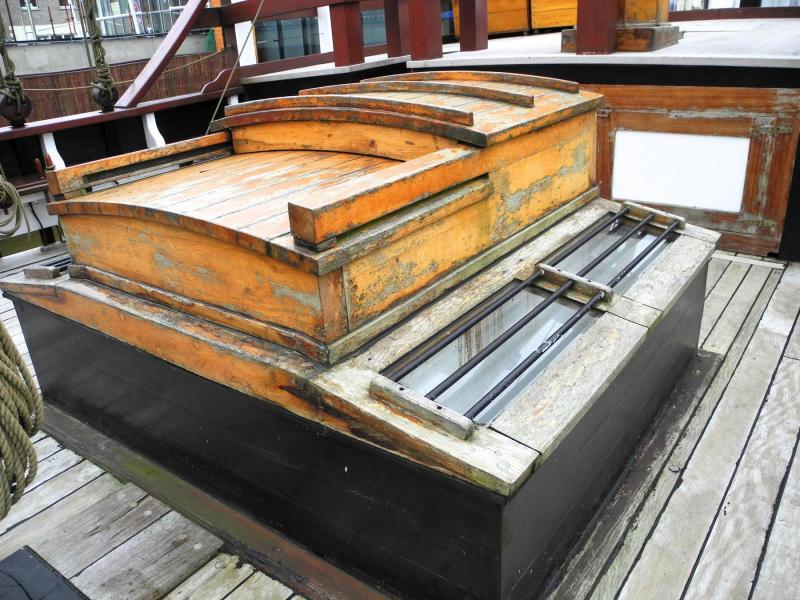
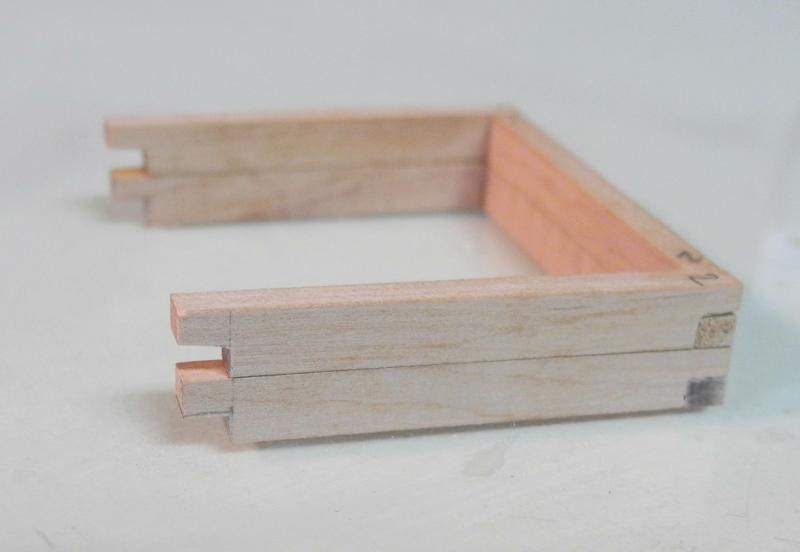
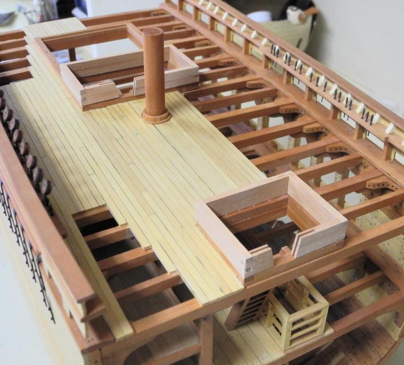
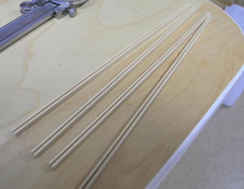
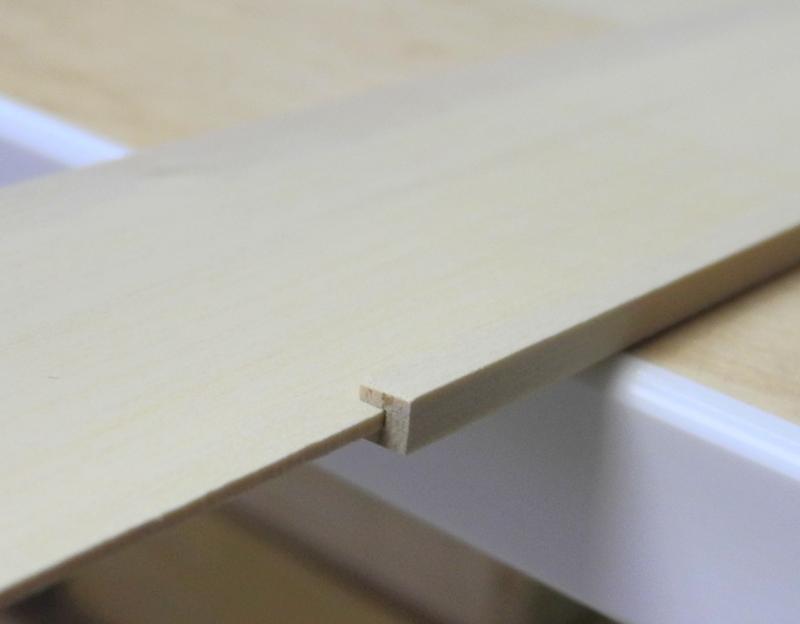
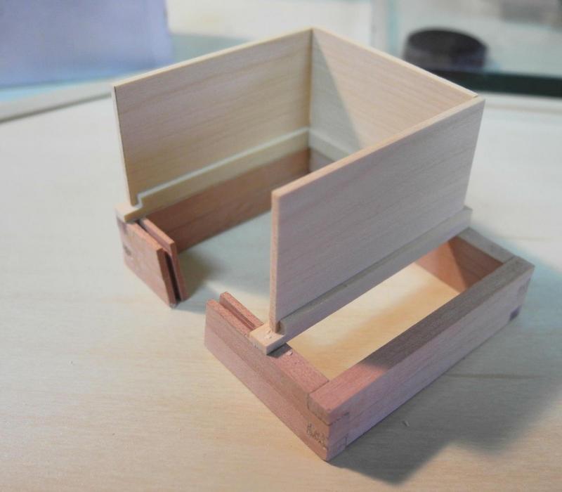
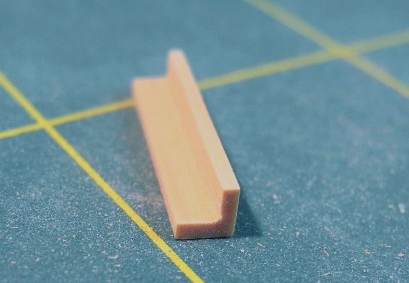
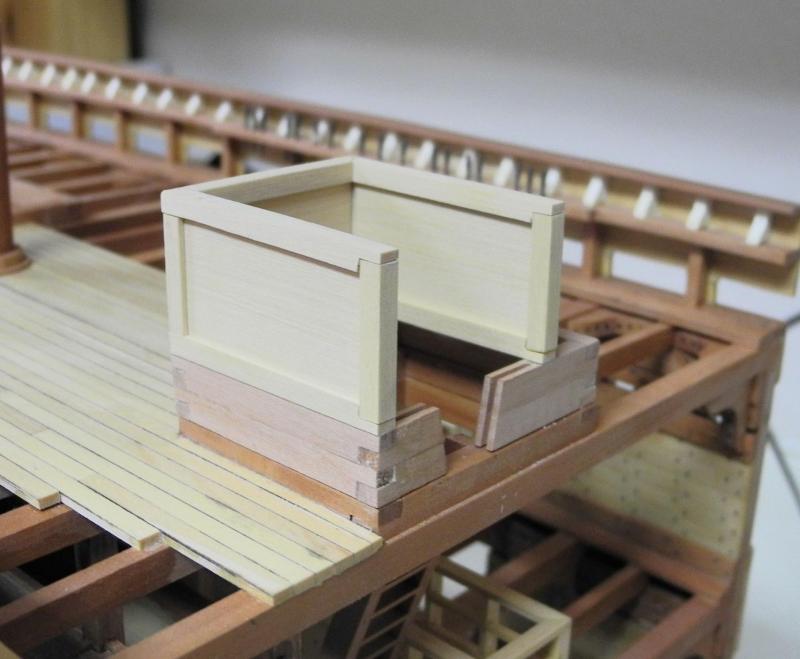
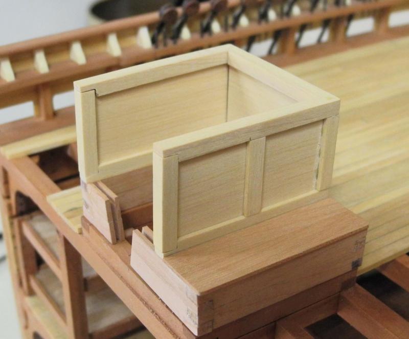
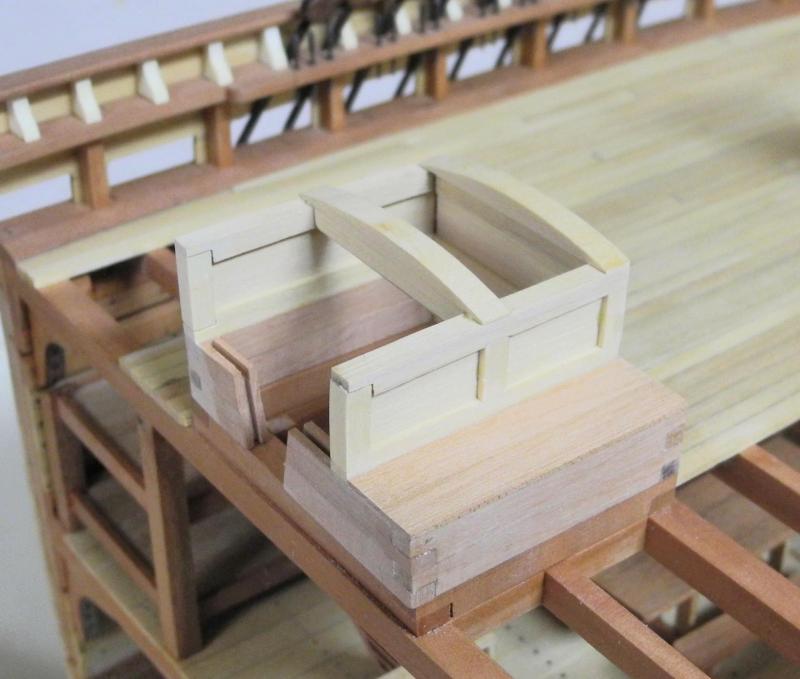
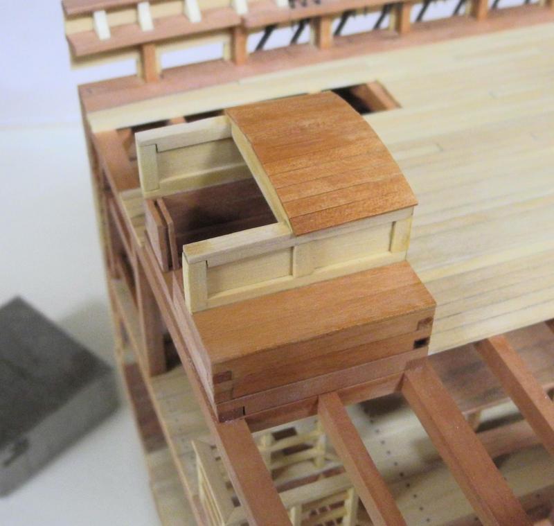
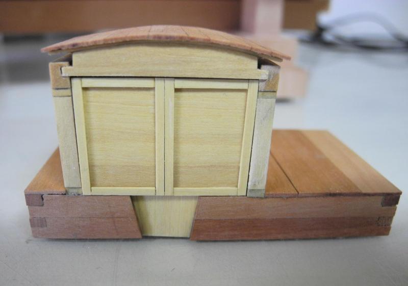
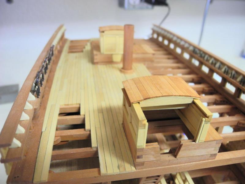
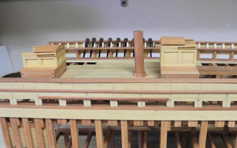
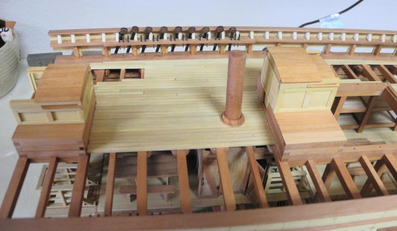
Part 53 – Companions It’s been a while since my last post as a result of chores that needed to be done, planned travel, holidays, and some bronchitis. During that time I spent a lot of time thinking through how to build the companions over the two ladderways from the main deck. The companions on the replica ship are constructed with curved sliding roofs, as shown in the following photos. I decided to build the companions with working sliding roofs so that I could choose how to display them. This makes the companions a fairly complicated construction project. The head ledges on the replica ship appear to be cut down to deck level, presumably to allow safer passageways for visitors, as shown in the first photo above. I don’t think this would have been done on the real ship, since it would allow water to reach belowdecks. I decided to leave the head ledges as built. The first part of the construction was to add two more layers of beams to the ledges as a foundation for the companions. A passage opening was left in these layers, and the opening was grooved to allow the installation of a hatch board in the opening. Railings for top and bottom of the walls were milled from 1/8” square stock, and a .042” slot was cut through these railings. .041” Sheets were milled for the walls of the companions and these sheets were test fit to the milled slots. The railings for the base of the walls were installed on the beams, with the rear corners mitered. A half-lap was cut into the front of the side pieces to accommodate a vertical beam. As can be seen in the above photo, the companions don’t cover the entire hatch, but are located to enclose the ladderway and the associated clearance space. The rest of the hatch will be boarded over. The wall panels are slip-fitted in place. Corner molding was prepared for the back corners of the companions. Top rails installed are a mirror image of the bottom rails. A center pillar was installed on the sides and the end panels to provide a finished appearance. Both companions were worked on in each step. When this point was reached I discovered that my measurements for the height of the companions were wrong. I had based the measurements on the photo (above) that shows a woman standing by the Main Hatch Companion, and assumed (incorrectly!) that both companions would be the same height. In reviewing the following photo, it’s clear that the aft companion is considerably shorter than the main companion. This also accounts for the fact that the aft (shorter) companion only has hatch panels for closing off the entry, while the main hatch has a combination of doors and panels. I carefully separated all of the companion pieces, reduced the height of both companions to their more appropriate sizes, and reconstructed the companions. The following photo shows the aft companion resized, and with curved roof beams in place to support the fixed part of the roof. All of the curved beams were carefully cut on the scroll saw and finished on the disk sander. The following photo shows the fixed roof in place and the entire companion finished with wipe-on poly. The sliding portion of the roof will ride on rails mounted to the forward part of the companion wall and extending over the fixed roof. These rails were slotted to provide tracks for the sliding roof. The cross beams for the sliding roof were cut on the scroll saw. The piece at the top of the photo is the aft beam that will traverse the fixed roof. The piece at the bottom is the forward beam, and the extended bottom of the beam serves as a stop for the sliding roof. A .020” slat was fixed to the top of each beam to provide an overhang for the roofing and to secure the beam in the slot. 1/8 x 1/32 planking was used as roofing for all of the companion roofs, both fixed and sliding. The following photo shows the aft companion in place with an open roof. The main companion has a hatch board and doors in place, with the roof closed. Simulated hardware will be added to these doors at a later time. The companions are temporarily in place. Cross braces still need to be added to the sliding roofs, and as mentioned above hardware needs to be added to the main companion doors. In addition to that remaining work, the capstan and one set of bollards still need to be prepared. Getting very close to the end! Thanks everyone!


- 649 replies
-
- 24
-
-
- dunbrody
- famine ship
- (and 2 more)
-
Shadow looks at home in the water. Besides being beautiful, she seems nicely balanced. Bravo, Patrick!
-
Very nice work, as usual, Ed. I'm amazed at the number of bands on the mast. As you mentioned, I also find myself redoing a lot of work as I develop the correct sequence and process - it certainly pays off, as seen in your results.
- 3,618 replies
-
- 2
-
-
- young america
- clipper
- (and 1 more)
-
Hi Gary Great to see you posting again. I think the lighting will pay dividends for you.
-
Hi Patrick: I've experienced a similar 'time-out' from my Dunbrody, so I'm very happy to see you back to work on Shadow. She's absolutely beautiful - love the lines and love the workmanship. Welcome back! Frank
-
Thanks Mike. I didn't have any experience with making tiny belaying pins either, but Ed Tosti's posts on how he made them for Young America were very helpful and showed the way.
- 649 replies
-
- 6
-
-
- dunbrody
- famine ship
- (and 2 more)
-
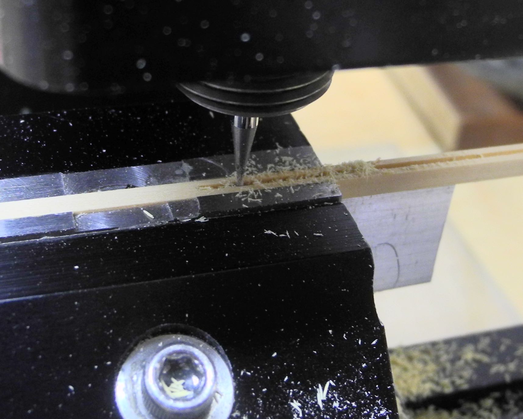
Hi Jack That's a good question. I would think you could use a Dremel router setup to make similar jigs, as long as you're able to mill straight lines and can be sure to make perpendicular cuts when needed. I would think that even small chisels could be used if the jig is wood. Since I'm using the mill, the depth of the cut is controlled by the z-axis hand wheel. With the Dremel setup I would think that it's just a question of making shallow cuts and measuring the depth after each cut until you reach the depth you want. As far as the use of Corian - I use that primarily for jigs for soldering. I also make jigs from wood and aluminum flat stock. I use wood when there's no danger of the wood glue making the piece stick to the jig, although this problem could probably be avoided by first putting a coat of poly or some other finish on the jig that would inhibit the glue from adhering to the jig. Hope this helps.
- 649 replies
-
- 8
-
-
- dunbrody
- famine ship
- (and 2 more)
-
Thanks Gary. This build has been quite a learning experience for me, and my hope is that I'm helping some other modelers by documenting the ups and downs along the way. Thanks Rich! Enjoy the show today - hope to see you there.
- 649 replies
-
- 5
-
-
- dunbrody
- famine ship
- (and 2 more)
-
I think I like them better in the front gun ports. But I see in the contemporary models that there aren't any empty gun ports shown in the photo - why leave any gun ports empty?.
- 1,051 replies
-
- 2
-
-
- cheerful
- Syren Ship Model Company
- (and 1 more)
-
Thanks, Michael. The jigs used for soldering and for forming the fife rails are made from Corian.
- 649 replies
-
- 5
-
-
- dunbrody
- famine ship
- (and 2 more)