HOLIDAY DONATION DRIVE - SUPPORT MSW - DO YOUR PART TO KEEP THIS GREAT FORUM GOING! (Only 51 donations so far out of 49,000 members - C'mon guys!)
×


Mahuna
-
Posts
1,504 -
Joined
-
Last visited
Content Type
Profiles
Forums
Gallery
Events
Everything posted by Mahuna
-
 Hi Bob - she's looking really nice. I'm thinking I'll have to come up soon - to get away from the heat for a day and to get a closer look.
- 348 replies
-
- 3
-

-
- pequot
- cable ship
- (and 1 more)
-
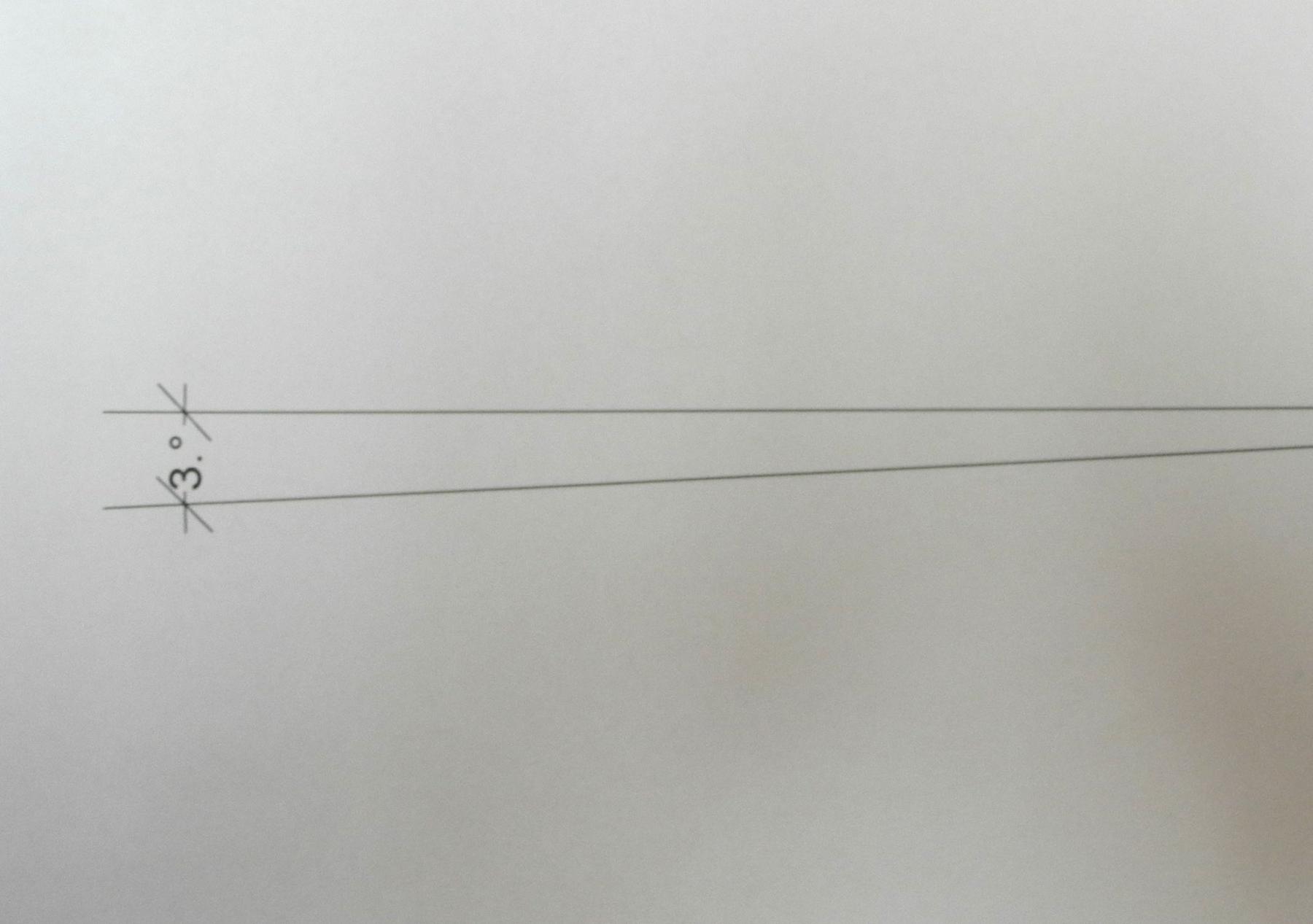
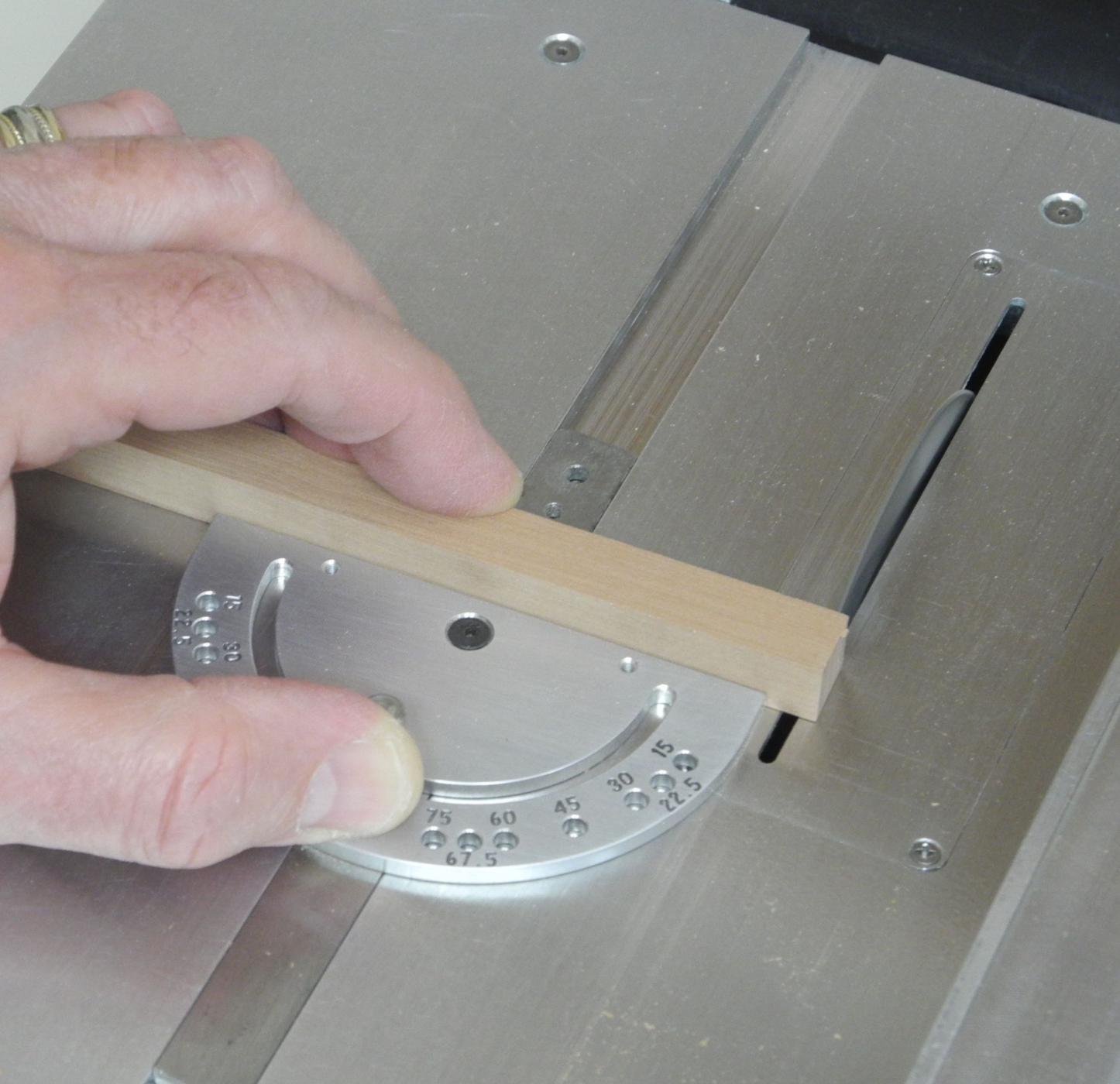
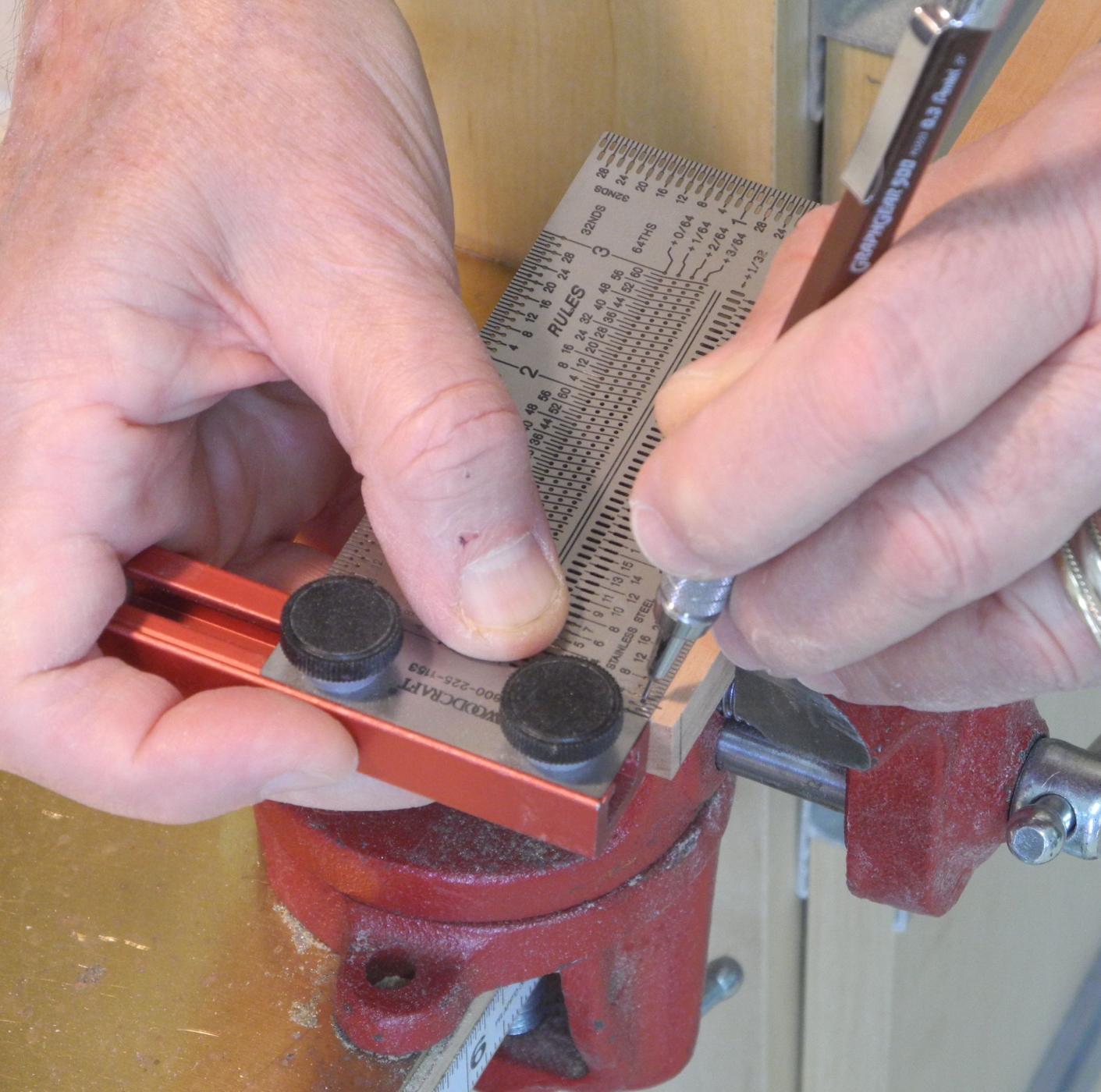
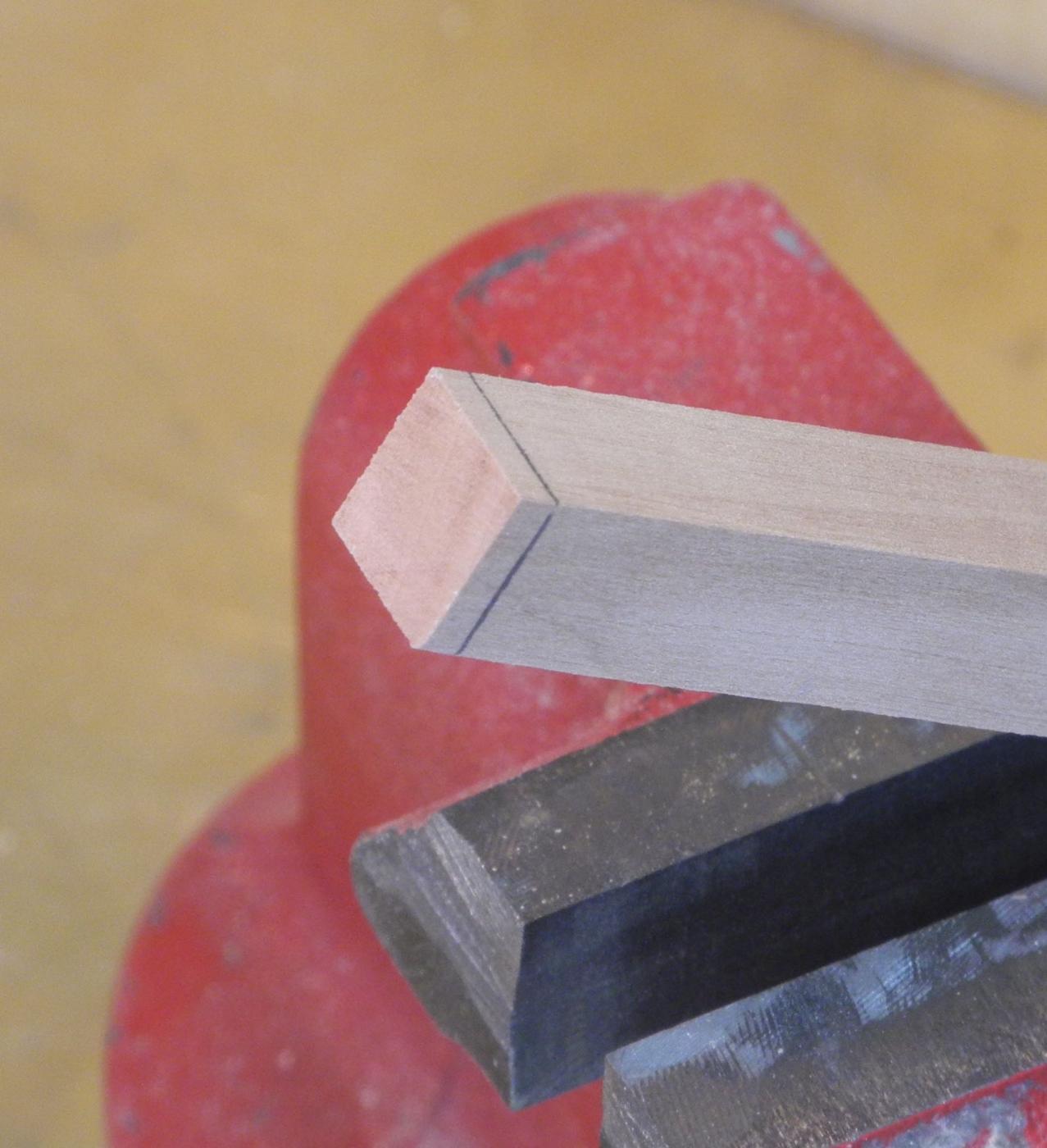
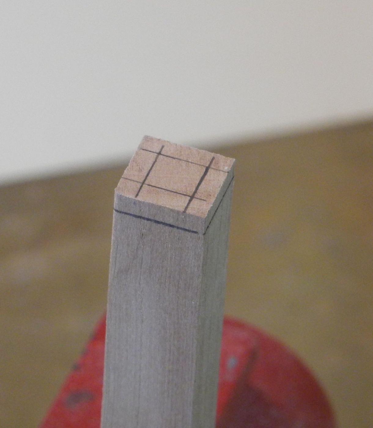
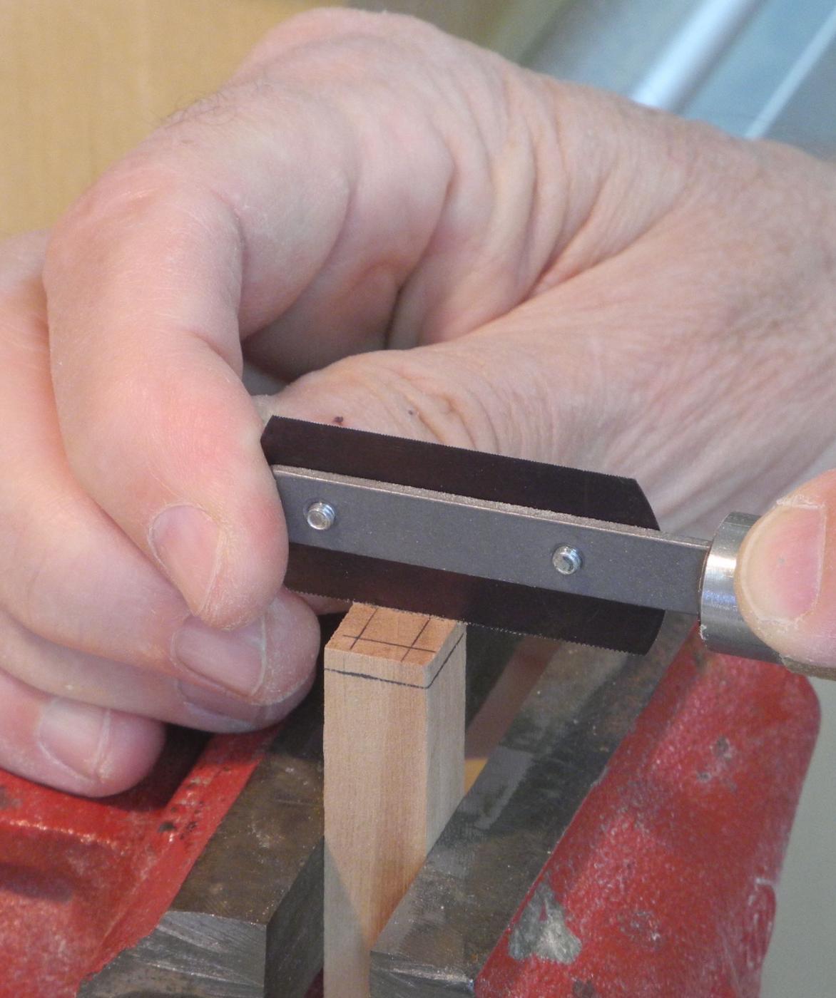
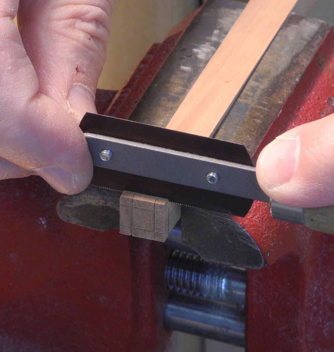
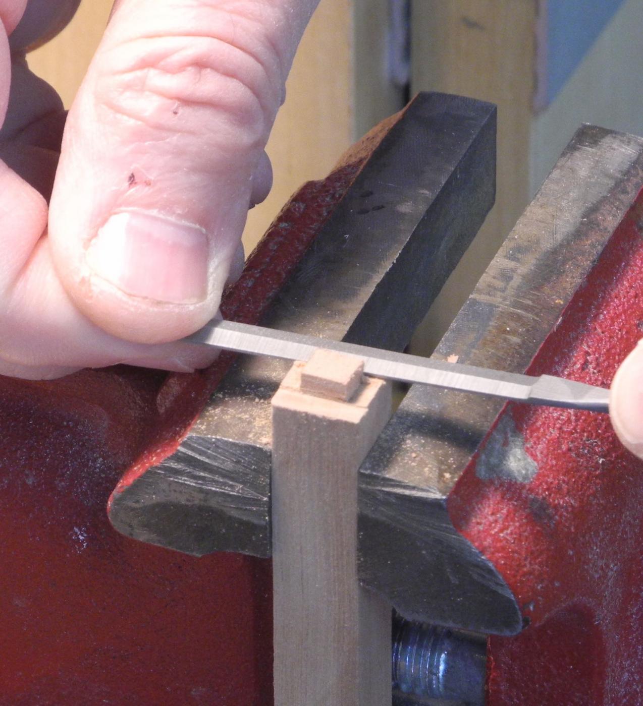
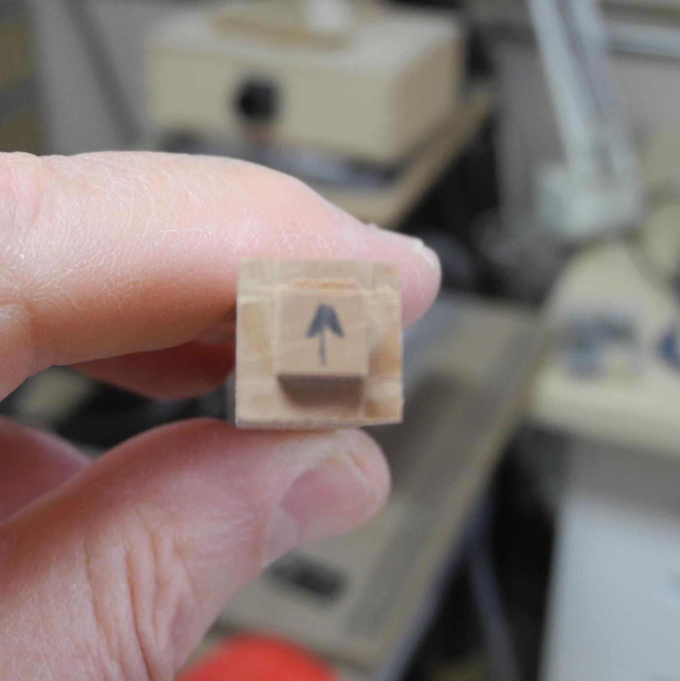
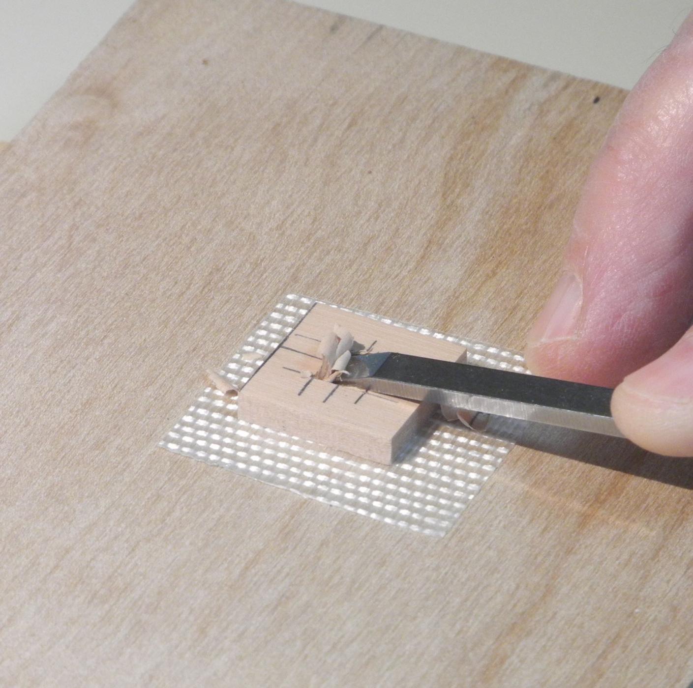
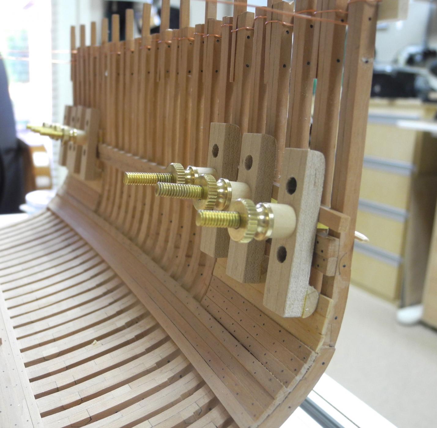
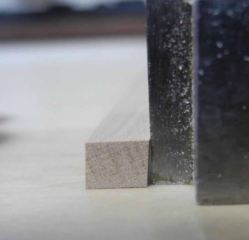
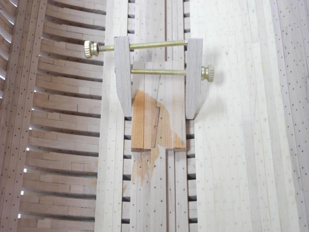
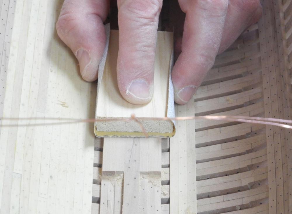
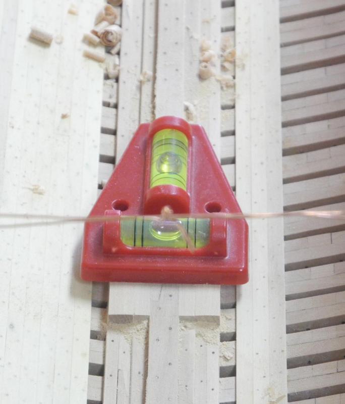
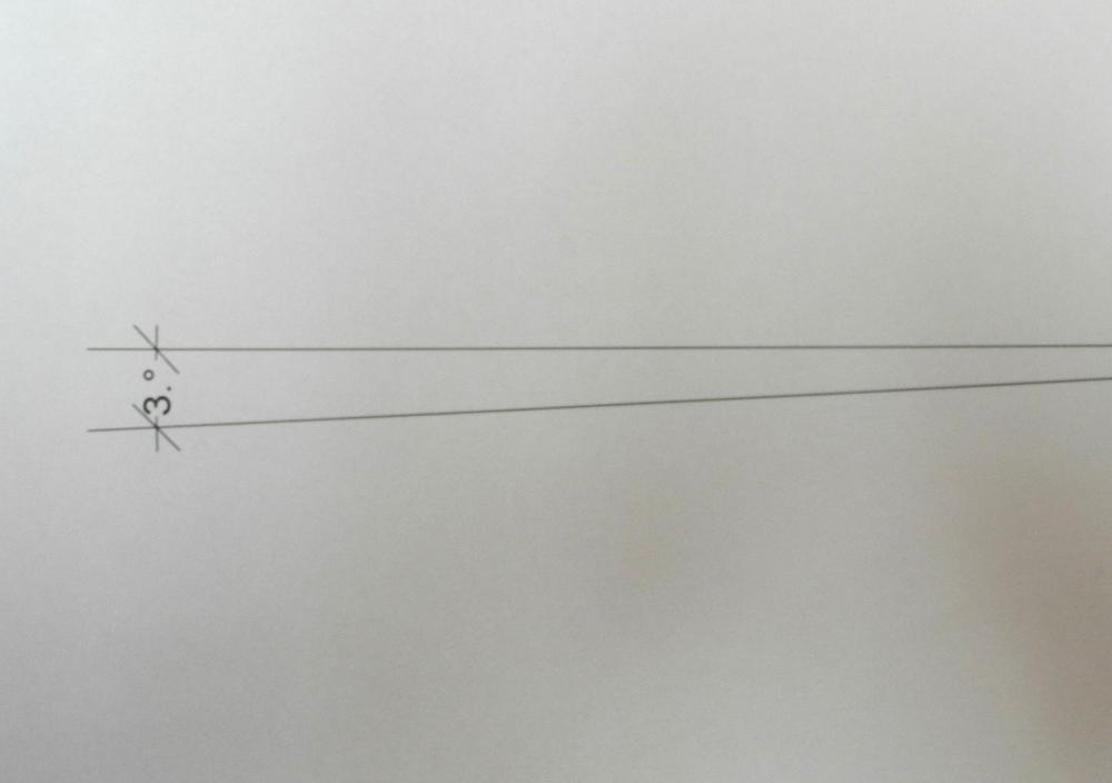
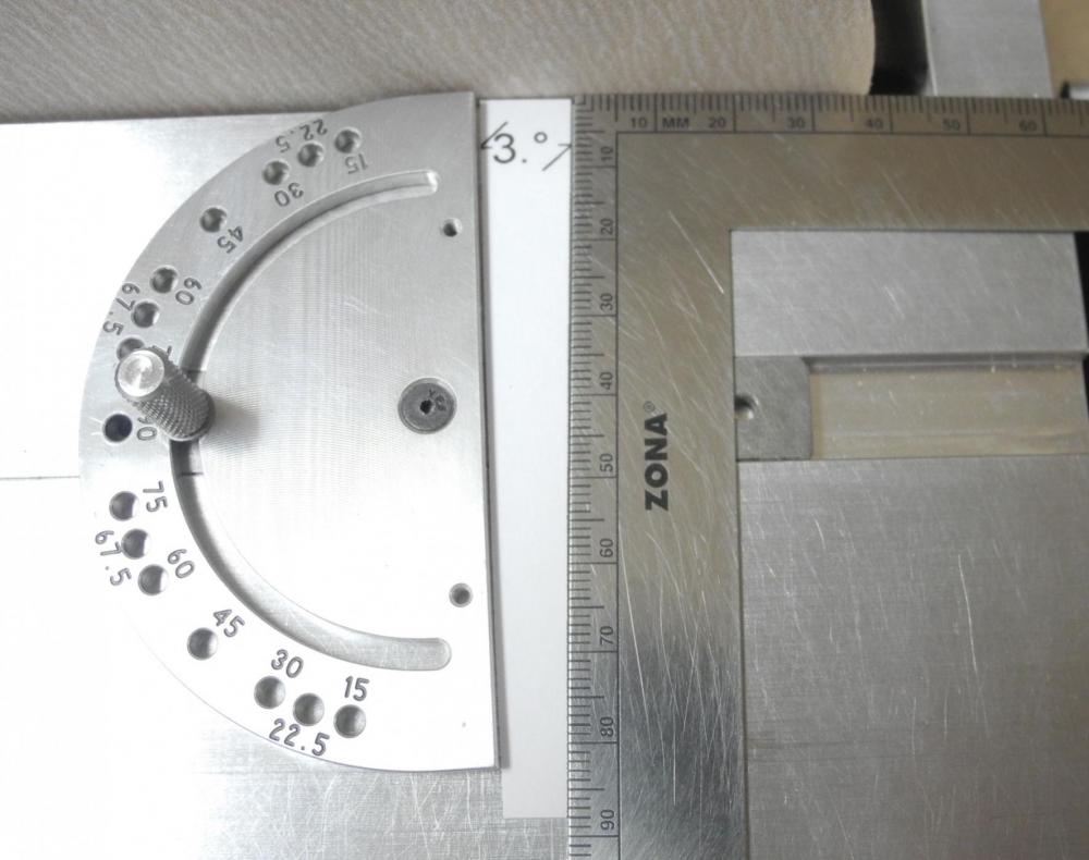
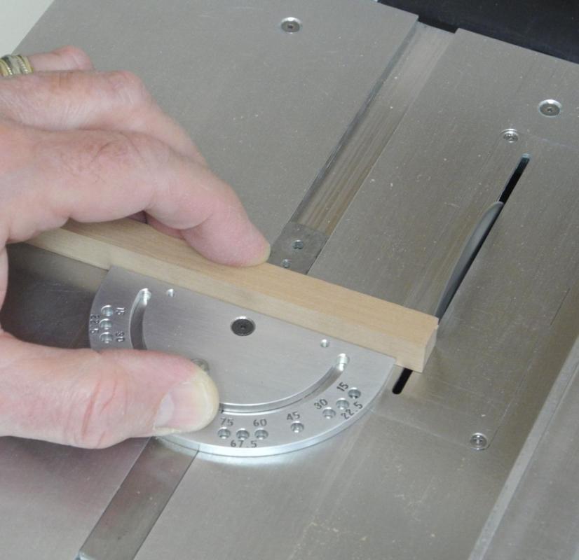
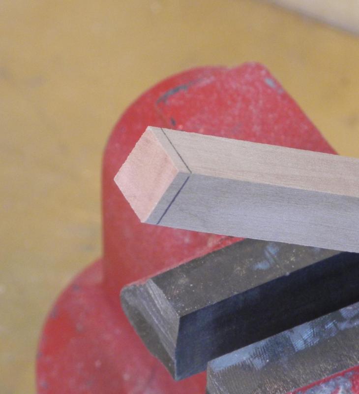
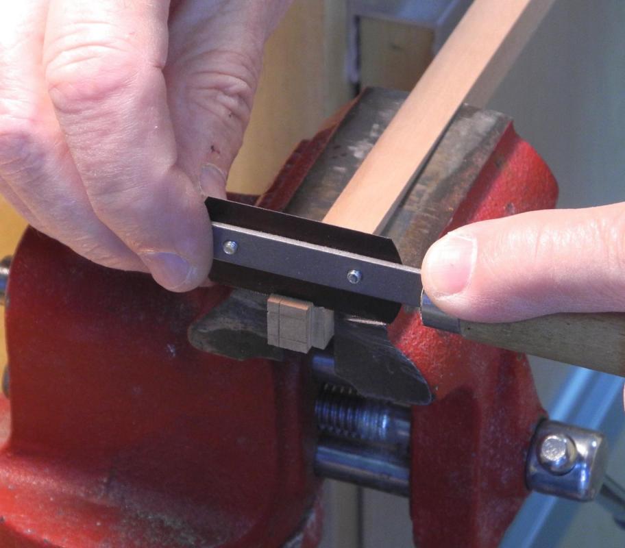
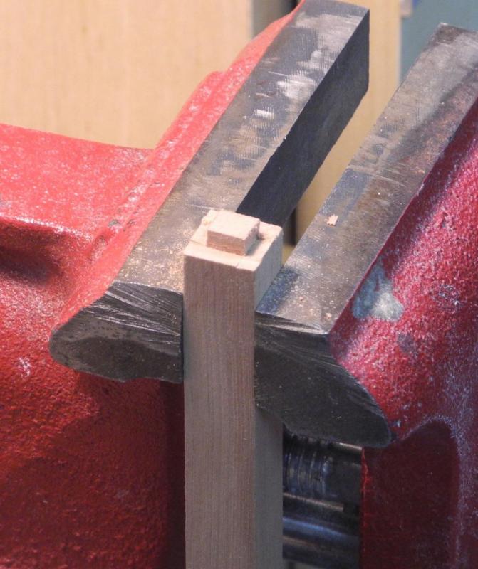
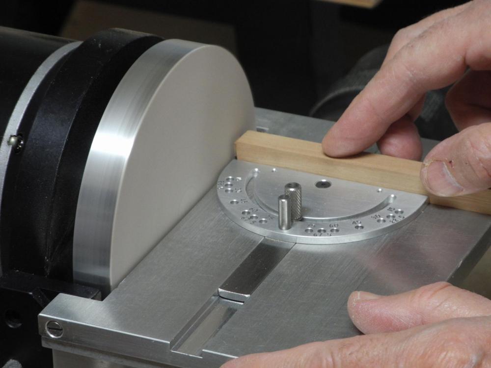
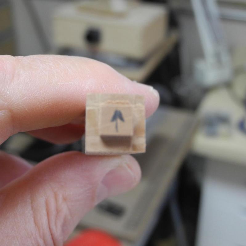
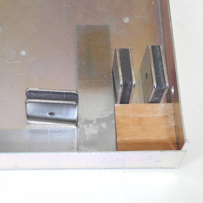
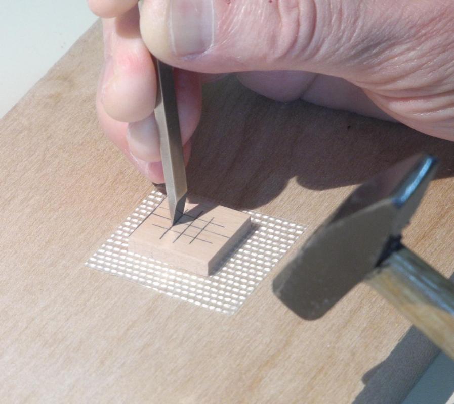
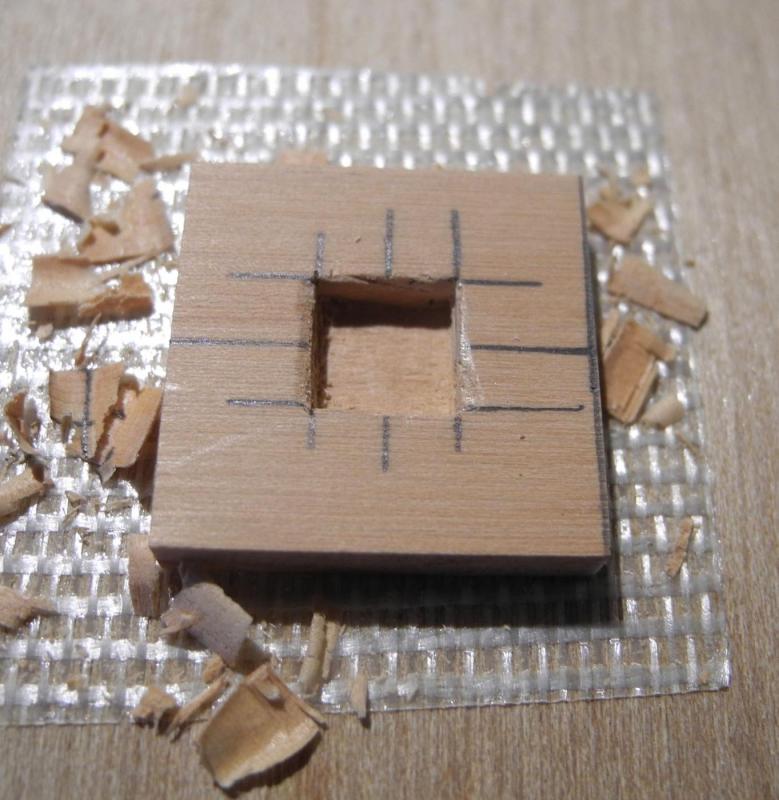
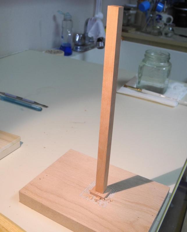
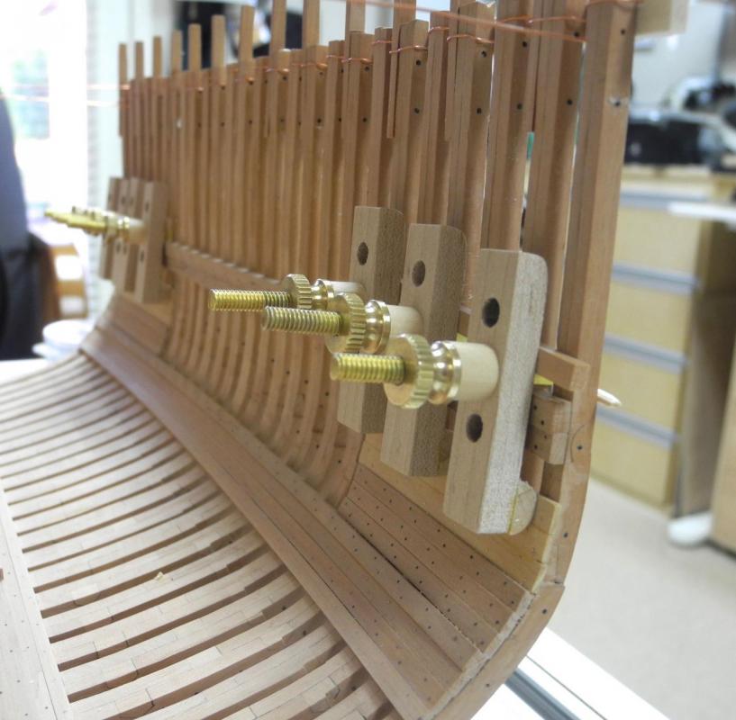
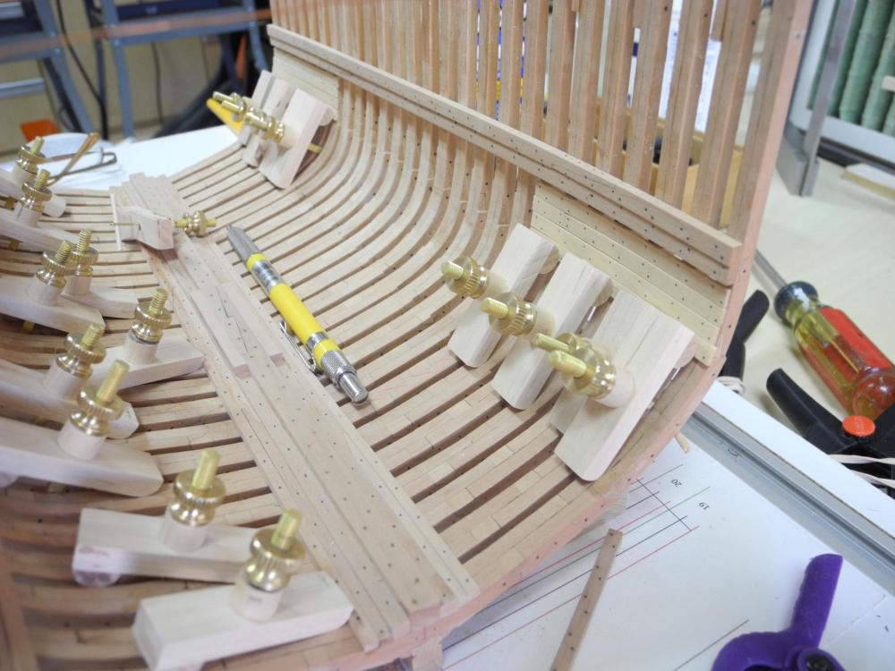
Part 24 – Mast and Mast Step The last work to take place in the hold is to build a mast step and the main mast that will rest in it. In American Built Packets and Freighters of the 1850’s, William L. Crothers briefly described the evolution of mast steps. By the mid-1800’s the additional Keelsons and their Riders required that a substantial foundation for support of masts be built. However, according to Crothers there is very little available information describing how these Mast Steps were constructed – he was only able to cite one drawing that he was able to find. The Dunbrody plans don’t show any kind of mast step – instead the only thing shown is what appears to be a plank laid on the keelson under the main mast. The plank measures approximately 5” thick and is about 7 feet long. I’m assuming that this plank would need to be wide enough for the foot of the mast, which is 20” in diameter. However, the Keelson on which it would sit is only 15” wide, so this doesn’t seem to be a very secure way to support the mast. In addition, the tenon of the mast would need to be less than 5 inches, or it would penetrate the Keelson. I didn’t feel comfortable that this was a workable way to secure the foot of the main mast, so I decided to make a Mast Step. I would use the diagram from the Crothers book and the mast step shown in Ed Tosti’s Young America to design my own Mast Step. The first item was to install a couple of timbers laying alongside the Keelson. These timbers are the same width as the Inner Sister Keelsons, and were sized so that the top of the timbers is at the same height as the Keelson. (Confession time – these timbers have been installed for quite a while, and have appeared in past photos – I just didn’t bring any attention to them. I installed them when I discovered the problem with the keelson’s scarf joint – I was thinking of ways to hide that joint.) In thinking through how to build the Mast Step, one issue was the fact that the Outer Sister keelsons were a step down in height from the Inner Sister Keelsons and also followed the slope of the floors as they rose from the cutting down line. This would make fitting any knees to the outside of the mast step problematic at the model scale. The solution was to mill a couple of timbers that were not square. They needed to be truly vertical on both sides, but the bottom face needed to be at an angle that would fit to the slope of the floors. I used a timber that started out square and sanded one face to the correct angle on the disk sander. I then used the thickness sander and, using the angled face as the reference face, reduced the thickness of the timber to the height of the keelson. These timbers were then glued to the other timbers The outer edge of these timbers were still higher than the level of the Keelson, so they were reduced by using a chisel, files, and a sanding block that spanned the entire area of the mast step. A bubble level was used to make sure we had a good, level foundation for the mast step. I thought it would make sense to make the mast stub before going any further with the construction of the Mast Step. An existing mast with a tenon already cut would make it easier to correctly size the mortice in the Mast Step. I first decided to make the mast out of cherry to bring a little variety to the appearance of the model. Unfortunately the cherry I was using had some flaws in the grain, and I gouged out a chunk when I was fairly far along in its creation. I then made a mast out of boxwood, but didn’t like the pale color – it appeared too weak. So I made a third mast out of madrone, and it was just right. The following photos show the process of making the mast, but they may change back and forth between the different woods. The main mast has a rake of about 3 degrees from vertical, so the first step was using CAD to make a template for this angle. I printed this template on card stock and used it to set the miter gauge on the disk sander to the correct angle. Since the Byrnes saw and the disk sander both use the same miter gauge, I moved the miter gauge to the saw and cut off the angle on the end of the stock for the mast. Using a T Rule and a .3mm pencil I marked lines for creating the tenon – first at the height of the tenon. Then the outline of the tenon was marked, using the same tools. A razor saw was used to cut at the lines. A small parallel Barrette (#2) was used to dress the shoulder of the tenon. The bottom of the tenon was still at the angle of the rake, and needed to be leveled – this was done on the disk sander at a 90 setting. And, having learned my lesson, I marked the forward face of the mast. Before finishing the mast, I decided to cut the mortise in the Mast Step. I decided to use a platform of heavy timbers set across the keelson platform. I glued them using a squaring jig. The following photos illustrate the process of cutting the mortise in the mast step – these photos are of a smaller platform that I made and then decided not to use. The platform is secured using carpet tape. As a test, the square mast stock was dry-fit to the mast step. The next post will continue the description of making the mast, the mast step, and the knees for the mast step. Thanks everyone!


- 649 replies
-
- 24
-
-
- dunbrody
- famine ship
- (and 2 more)
-
LOL - I wasn't recommending splices! The Cow Hitch that Dan shows in the second sequence is actually pretty easy, and keeps the remaining loose tail of the line facing inwards rather than having small ends sticking out.
-
Dan Vadas has an excellent description of tying ratlines. http://modelshipworld.com/index.php/topic/4179-what-knots-on-ratlines-edited-by-admin/?hl=ratline#entry124778
-
Thanks Mark. Hopefully there'll be a lot of progress to be seen at our next meeting in September.
- 649 replies
-
- 4
-
-
- dunbrody
- famine ship
- (and 2 more)
-
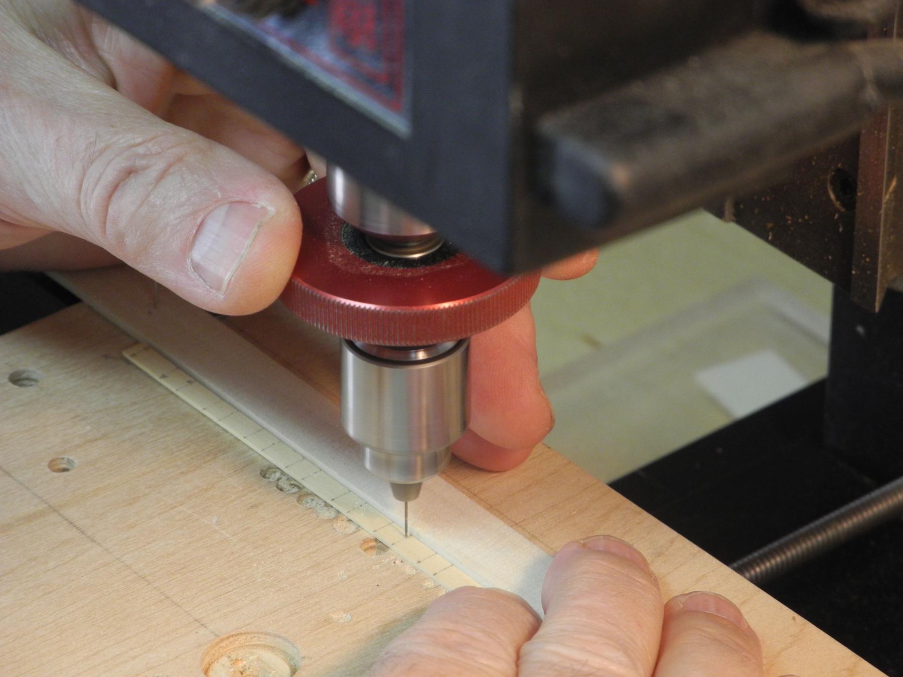
Hi Tom - glad the photos helped. My milling machine is a Sherline, and the Sensitive Drilling Attachment is made for it. I do think, though, that the same kind of setup would work on a mini drill press even without a sensitive attachment. I didn't use the x-axis feed for any positioning - I simply slid the plank by hand to the correct position under the drill. The Sensitive Drilling Attachment just kept me from having to continually crank the Z-axis screw feed.
- 649 replies
-
- 5
-
-
- dunbrody
- famine ship
- (and 2 more)
-
Thanks Brian. We'll find out soon. I'll apply a finish once the mast step is in place.
- 649 replies
-
- 3
-
-
- dunbrody
- famine ship
- (and 2 more)
-
Hi Patrick - wow, bad luck. I know you'l get it back together, but I'm sure it's not a happy time for you right now. After the fixing it will probably be like new, based on your skills.
-
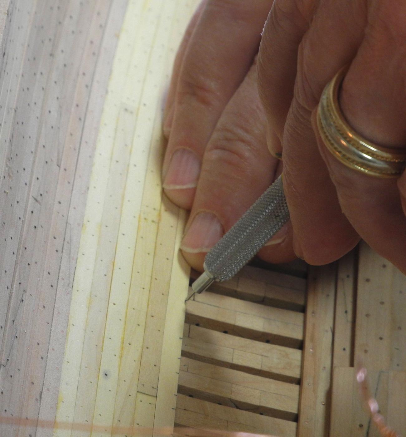
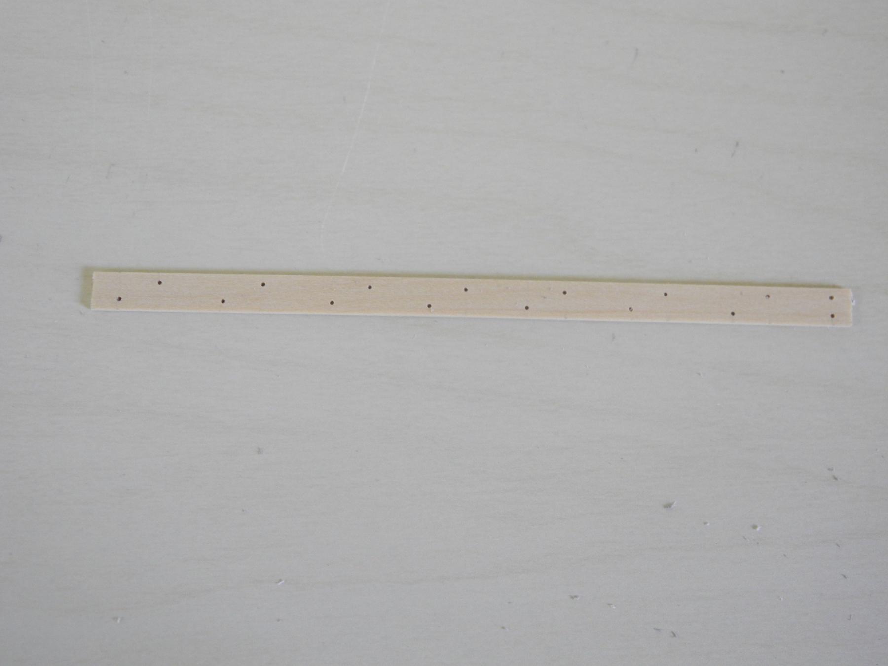
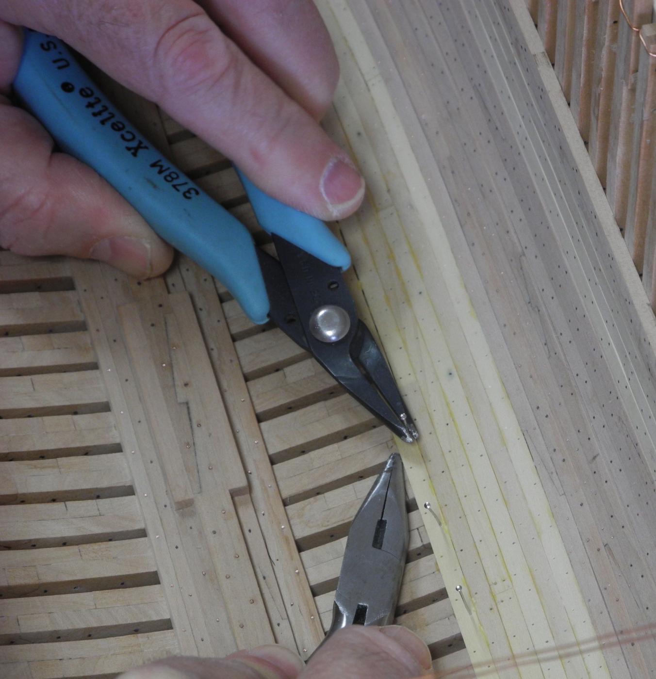
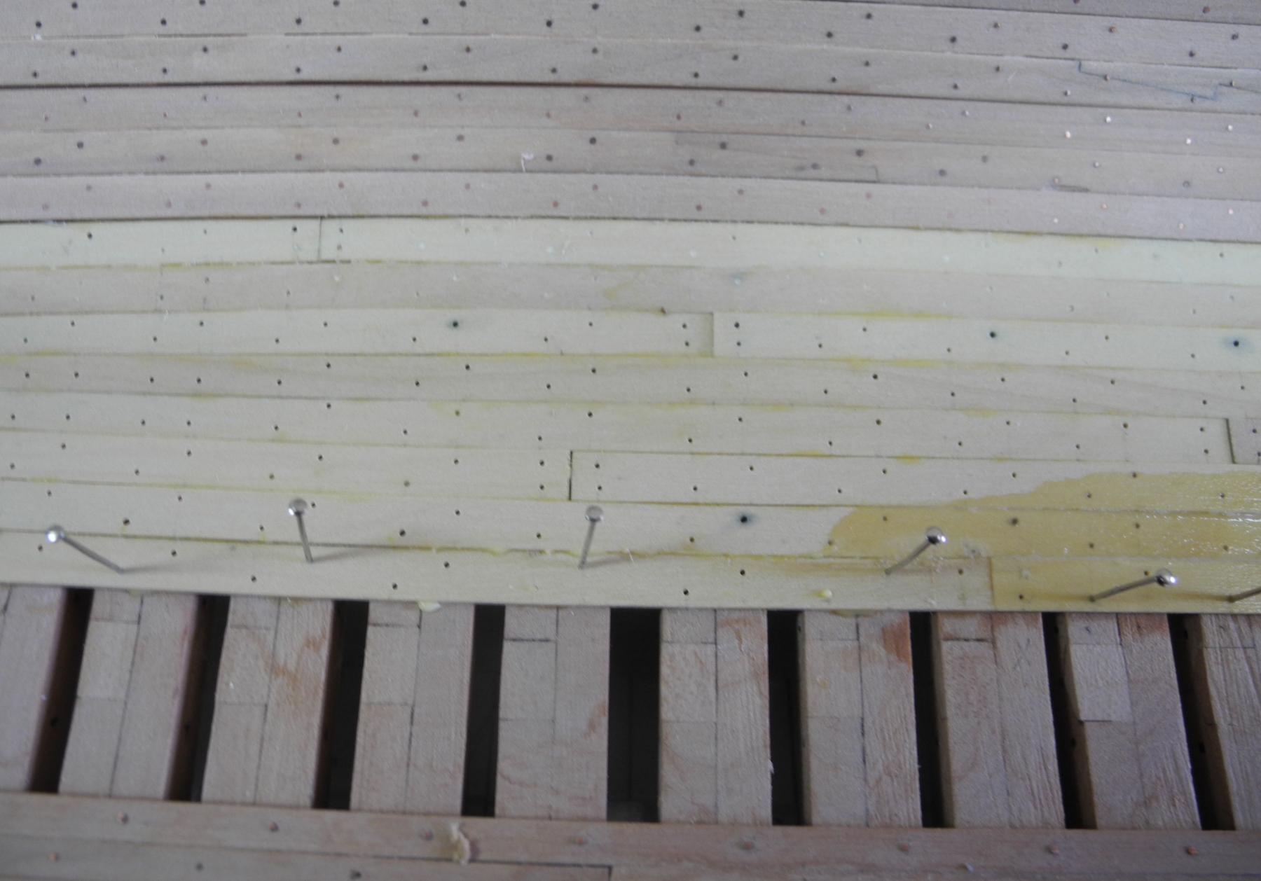
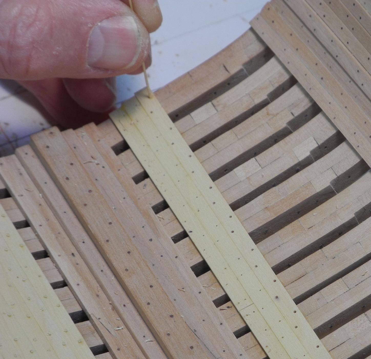
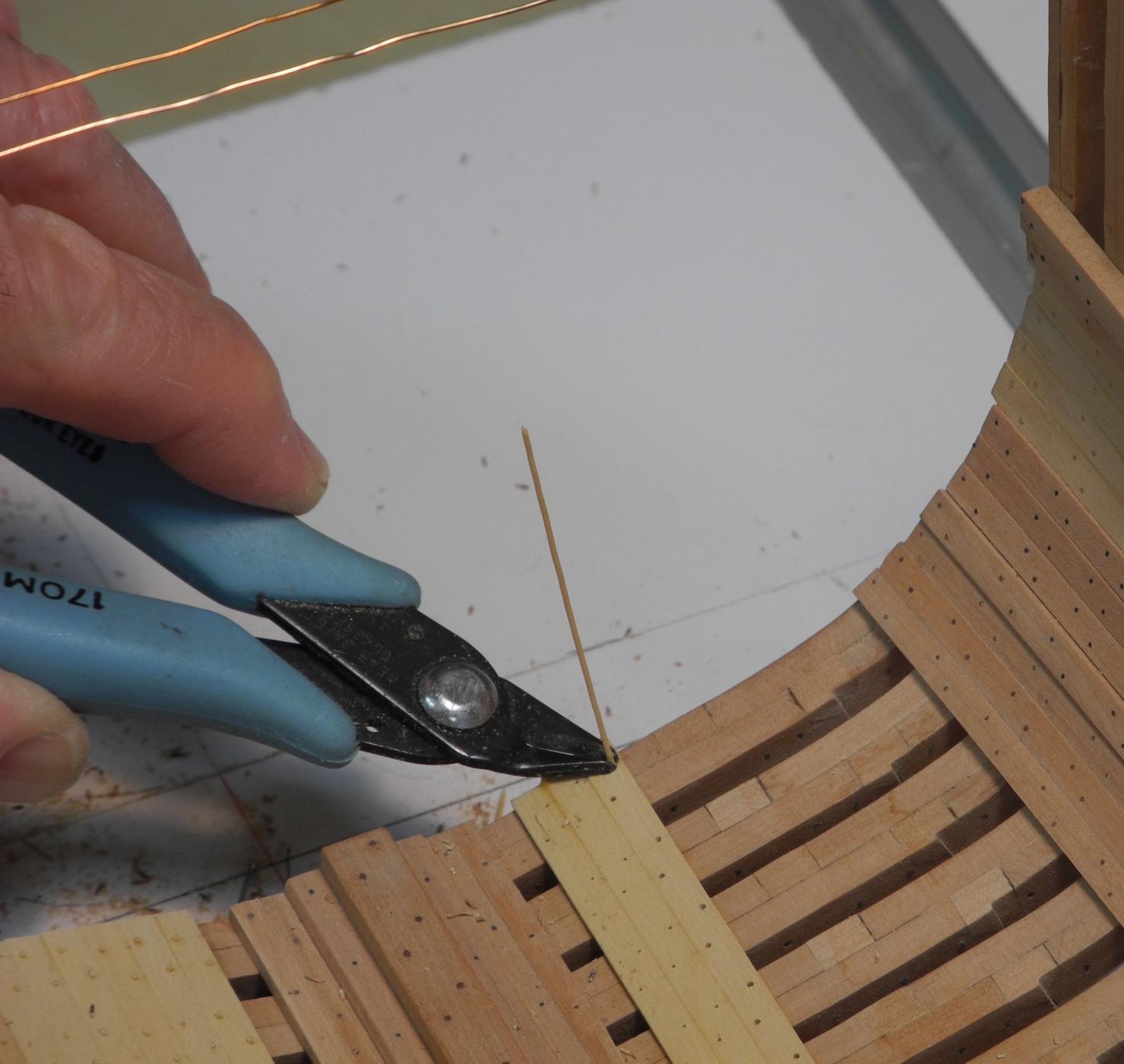
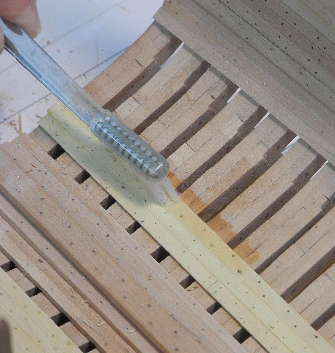
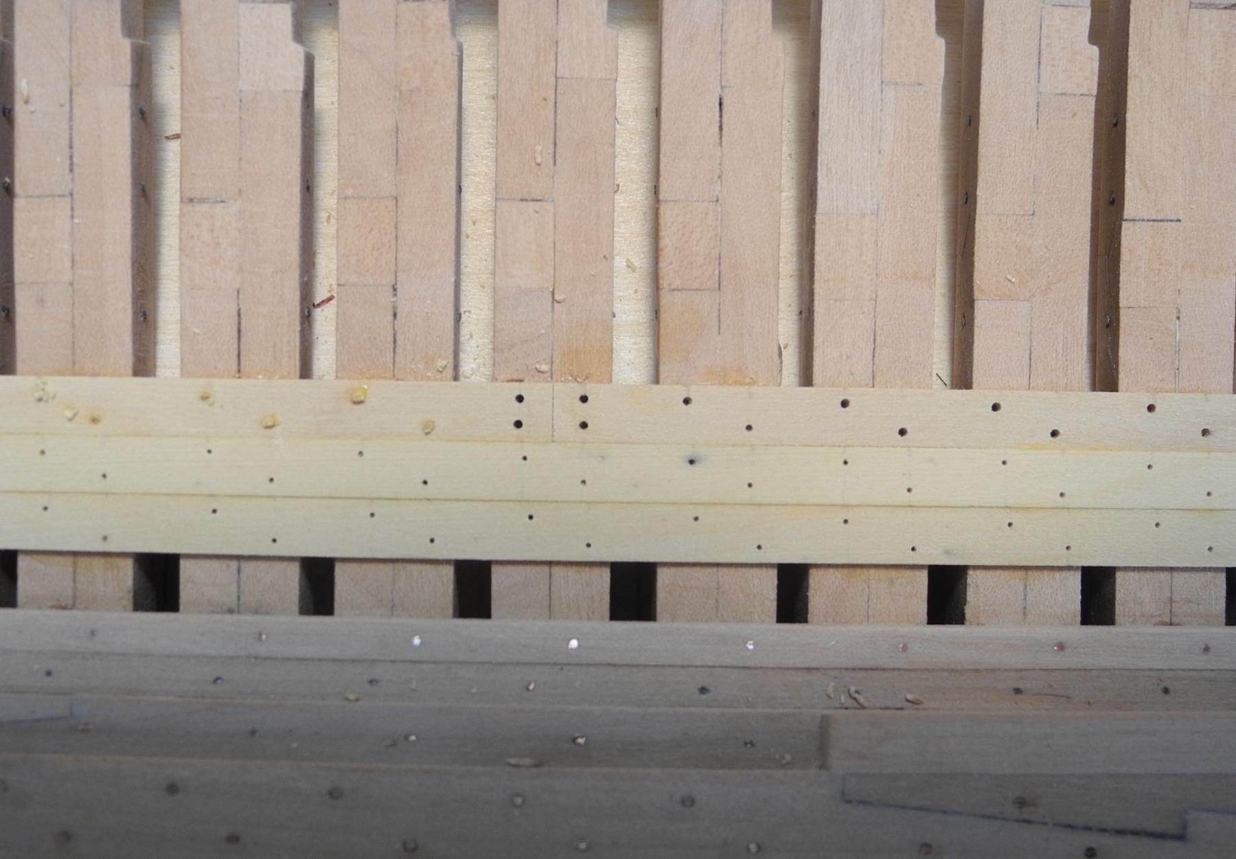
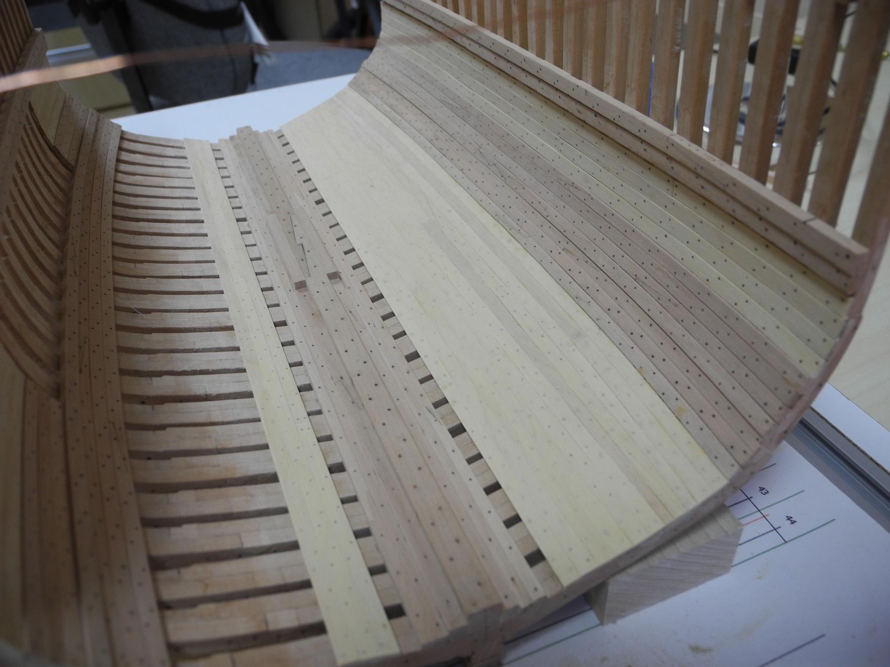
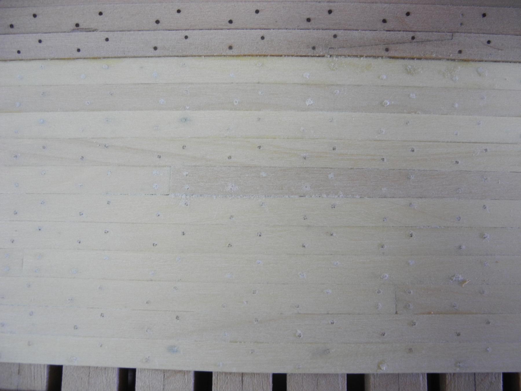
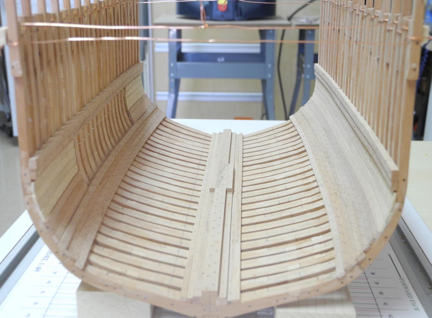
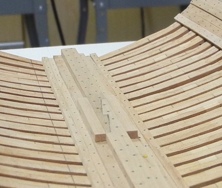
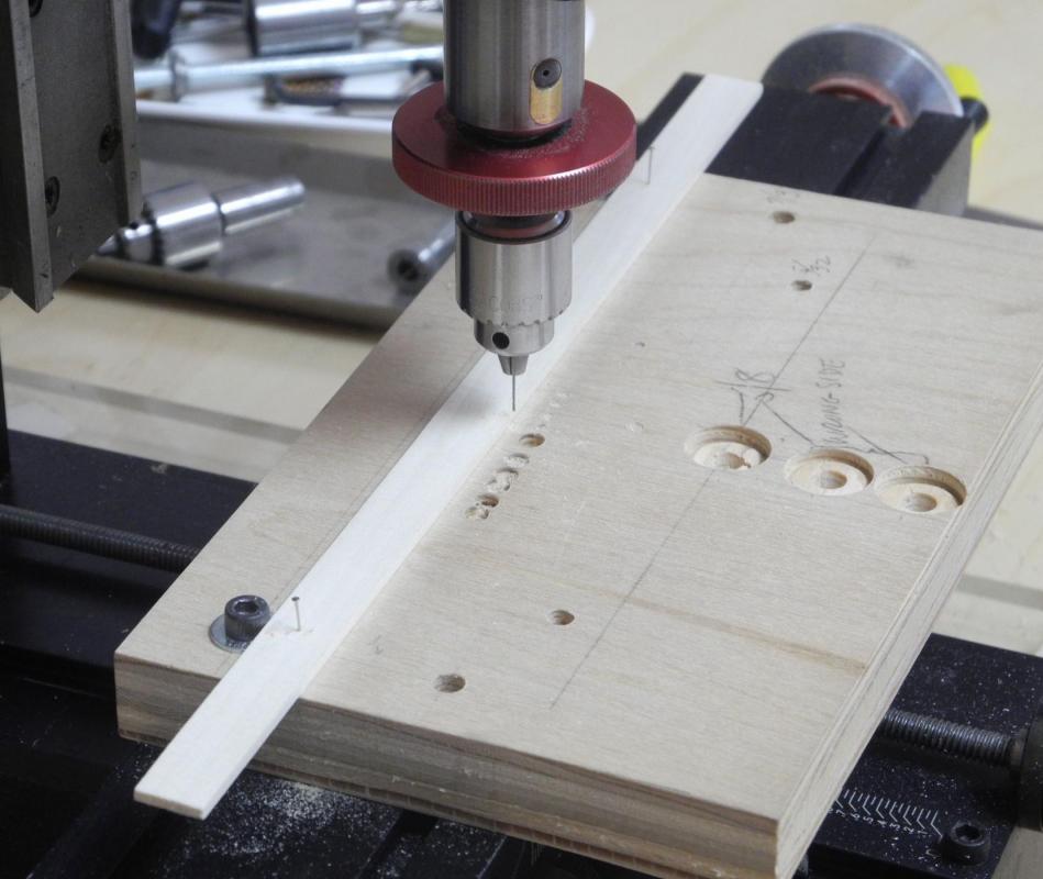
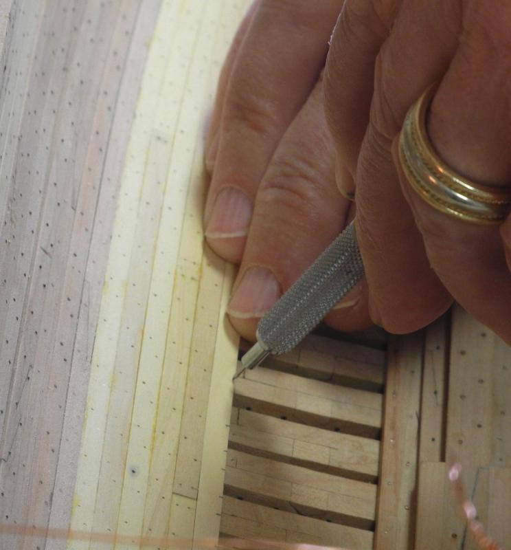
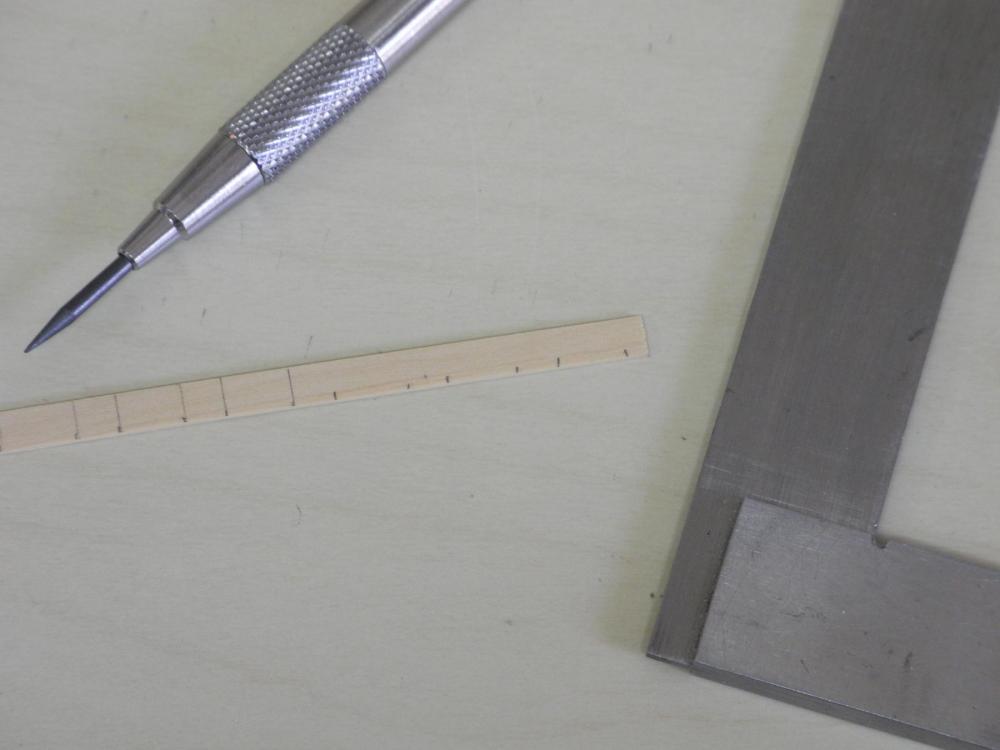
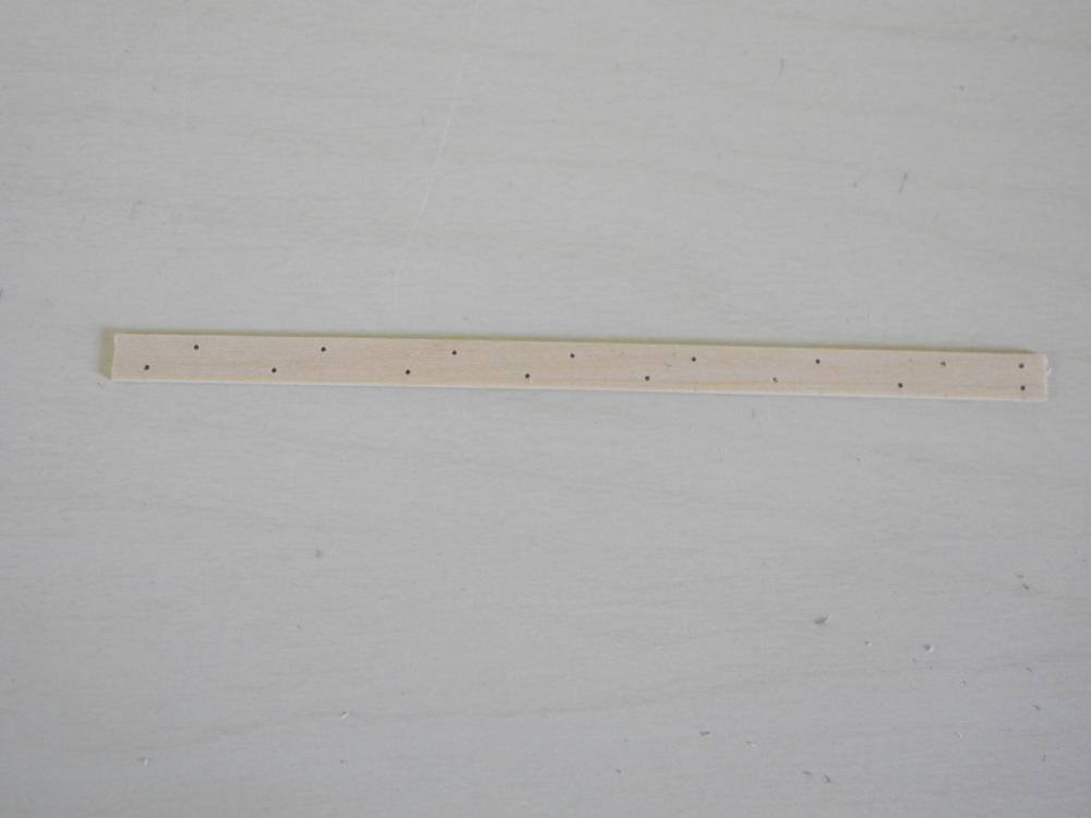
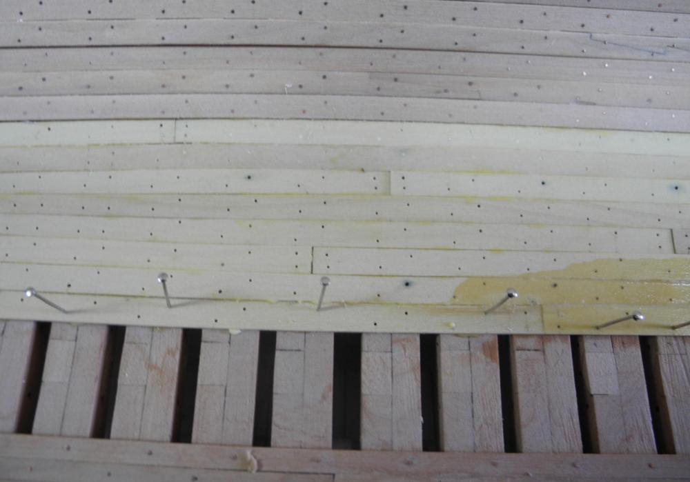
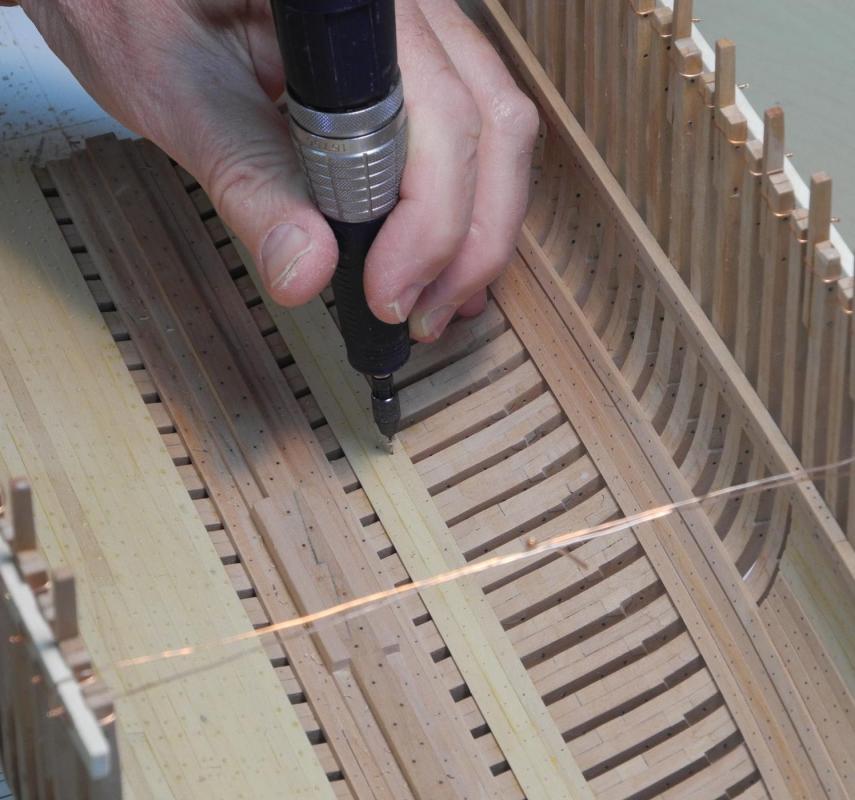
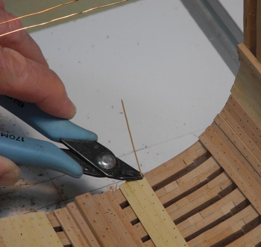
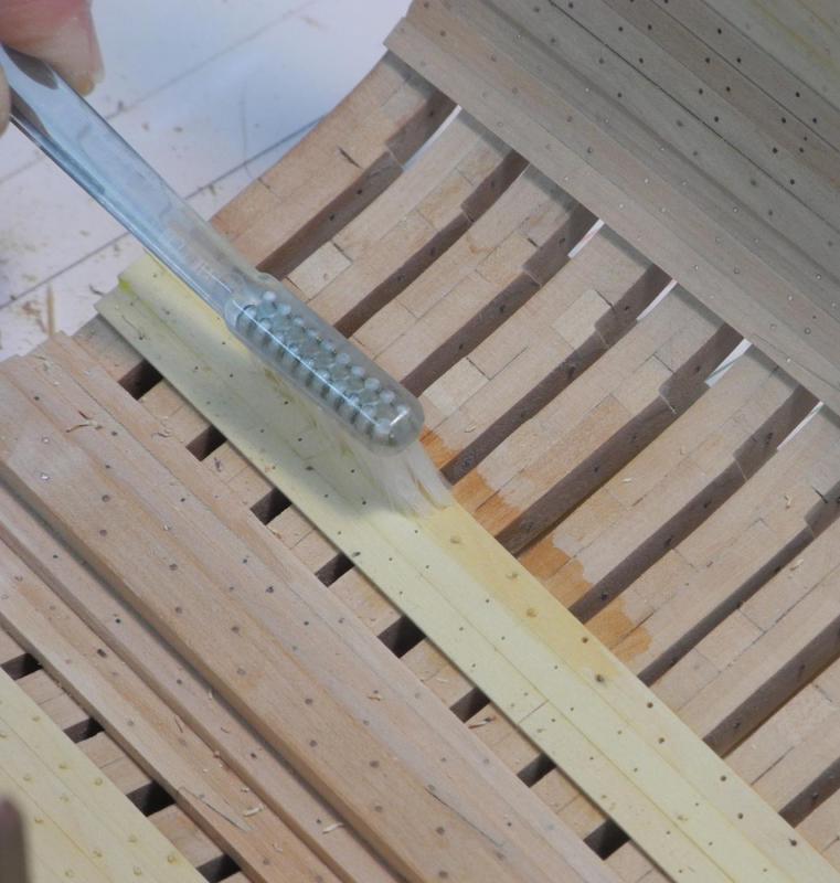
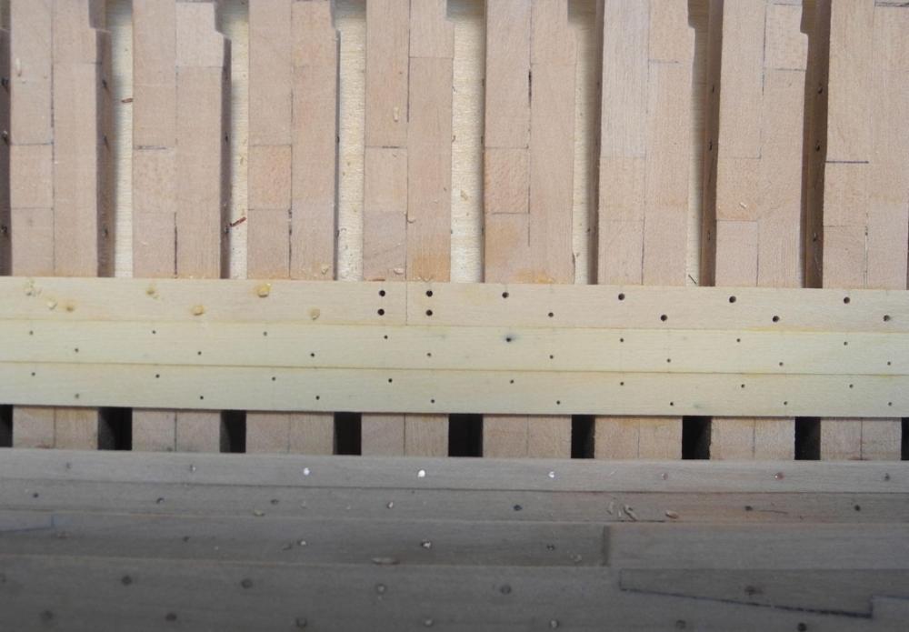
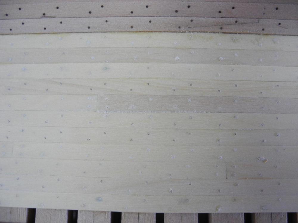
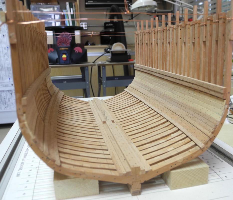
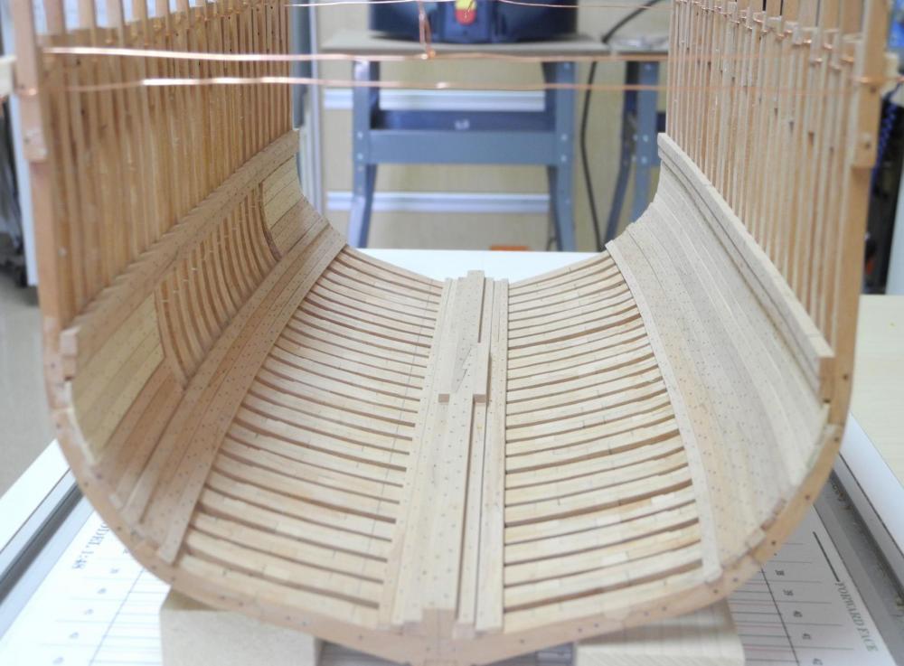
Part 23 – Floor Ceiling The next step after completion of the hold timbers is the installation of the Floor Ceiling strakes. There are 11 of these strakes between the lowest Second Stringer and the space that will be left for the Limber Strake. Originally I thought I’d need to install drop planks due to the curve of the hold timbers, so that I would have straight planks near the limber strake. The only thing I actually needed to do was to taper several planks at their ends. The Floor Ceiling planks are made of castello boxwood and are fixed in place using treenails. The treenails will be placed in the same pattern as was used for the bolts holding the hold timbers – one on each of the sister frames, alternating top and bottom edges until a butt joint. The butt joint will be held by treenails in the top and bottom edges of each plank. The holes for the treenails are pre-drilled using a #76 drill bit. These holes will provide a tight fit for the pins that will be used to hold the planks in place until the PVA glue sets, and will later be used as pilot holes for a larger drill bit to expand the holes for the treenails. I thought I’d share the process I use for pre-drilling these holes. The drilling is performed on the milling machine with a sensitive drilling attachment. A scrap piece of ¾” plywood serves as the drilling platform, and a piece of straight lumber is nailed to the platform to serve as a fence. The Y-axis is locked in place so that the holes are a consistent distance from the edge of the plank. The plank to be drilled is held in position against the previously installed plank, and a small mark is made to indicate the middle of the sister frame. A square is then used to draw lines for each of the hole positions on the plank. The holes are then drilled at the appropriate locations. On the Port side of the hull, the holes on the forward frame sister are drilled at the top of the plank. The holes for the aft frame sister are drilled at the bottom of the plank. This is accomplished by first drilling alternate holes for one side of the plank, then reversing the plank in the drilling fixture and drilling the remaining holes. The end for the butt joint will have a hole on both the top and bottom edges. In the hull timbers, this drilling is followed by inserting and gluing bolts made of copper wire into the holes prior to the timber being installed. For the floor ceiling the planks are installed immediately after drilling. Glue is applied to the frames on which the plank will be installed and on the edge of the plank itself. The plank is pushed into position, and pins are then used to hold it in place. In the following photo, the small pliers with the black jaws is being used to push the pin in place, holding the pin very near the tip (the pins bent fairly easily if they were held too high). The other pliers is being used to push the new plank against the adjoining plank. The pins were used on every other frame, and at varying positions. The plank on the left in the following photo has just been installed and glue needs to be cleaned off. The plank to its right is wet from washing glue off. Once all of the planks were installed, the treenails were then inserted. This was started by expanding the pilot holes using a #71 drill. The treenails were then dipped in PVA glue that was slightly diluted with water (about 1 part water to 2 parts glue) and inserted in the pre-drilled holes. The treenail was then clipped off. And after a few treenails had been installed the glue residue was washed off the plank. (The toothbrush I’m using is a narrow toothbrush used by periodontists – found on Amazon and very handy for narrow spaces). The following photo shows the hole configuration at a butt joint, and also shows the difference between the pilot holes and the final holes for the treenails. So the hold timbers and planking are now completed. The treenails are almost invisible at this point, but I’m hoping that they will be a little more visible after a finish is applied. The next step is to configure the mast stub and the mast step. Thanks everyone for following, and thanks for the ‘likes’ and comments – they’re much appreciated.


- 649 replies
-
- 25
-
-
- dunbrody
- famine ship
- (and 2 more)
-
Thanks Glenn. Progress will start to slow soon - I'll need to begin drafting the deck configurations and planning how to build them.
- 649 replies
-
- 4
-
-
- dunbrody
- famine ship
- (and 2 more)
-
Beautiful, Glenn. Your work continues to amaze me. I hope the local flooding does not affect you and your family.
-
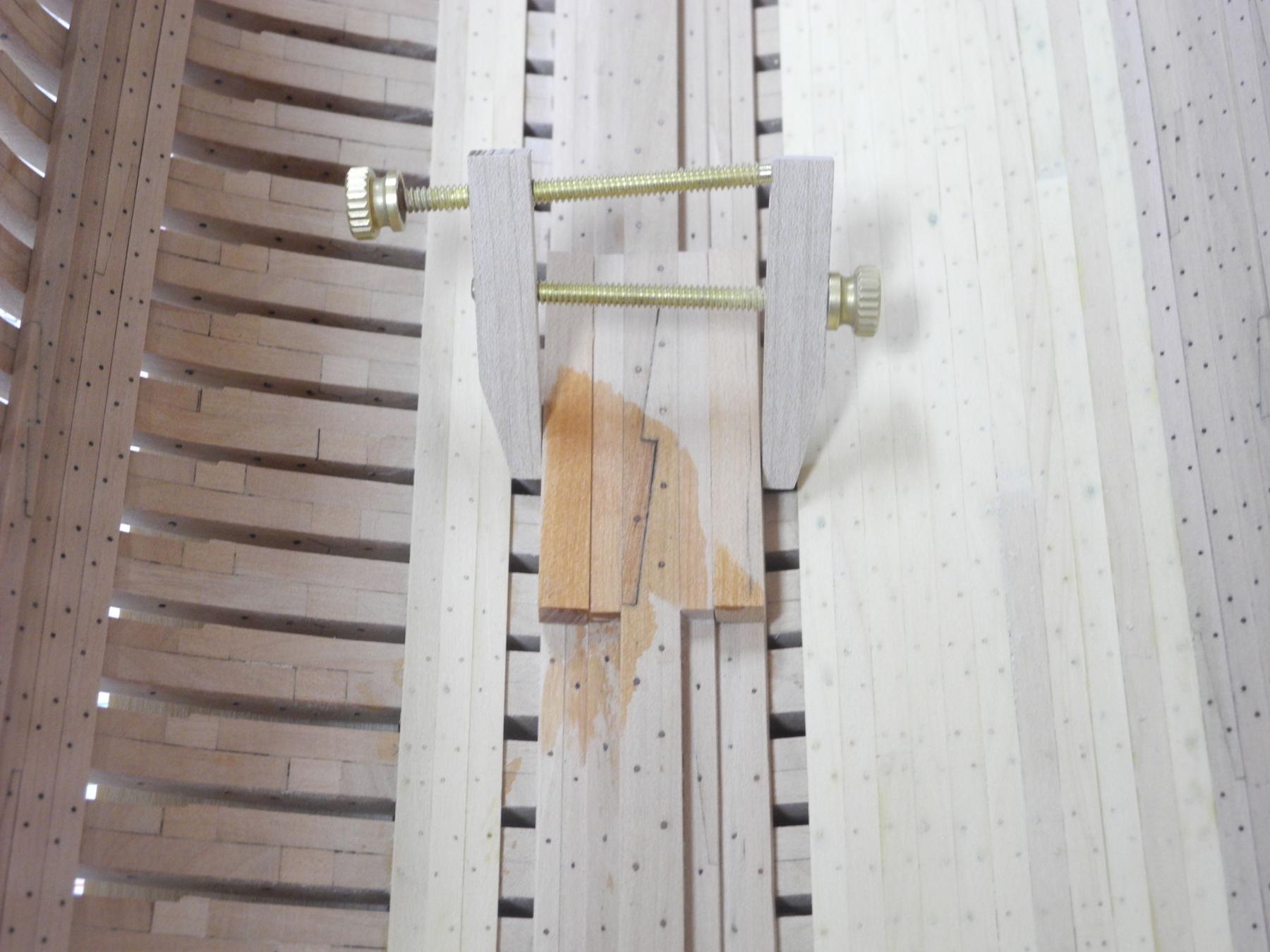
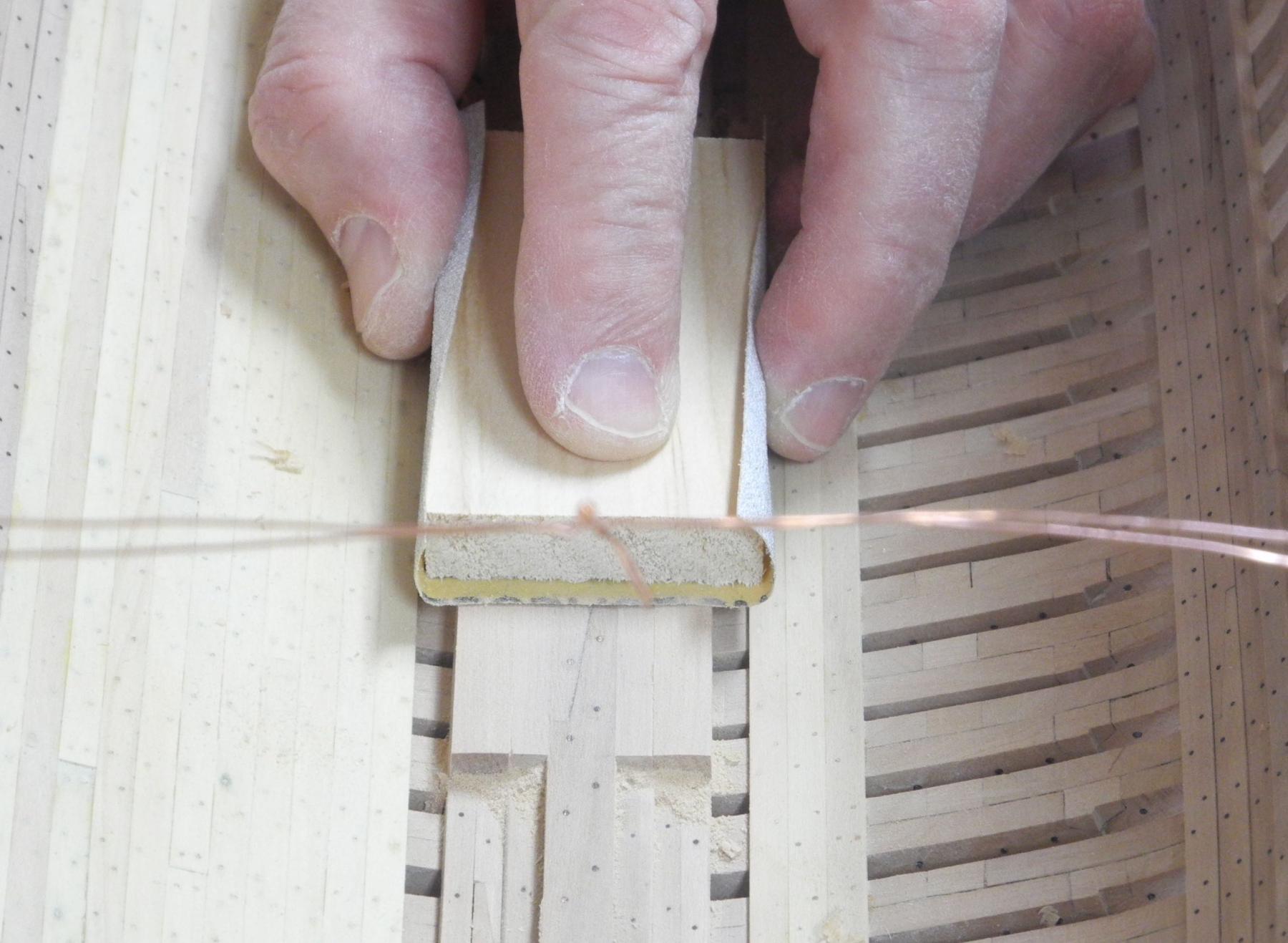
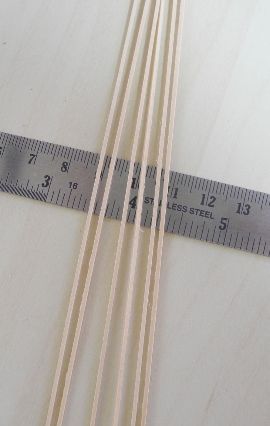
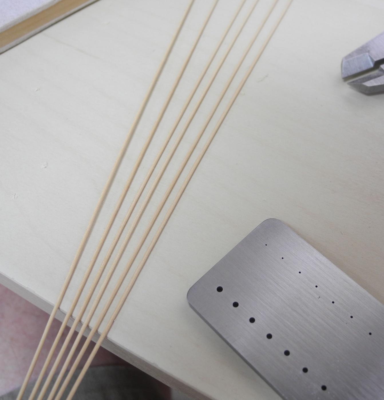
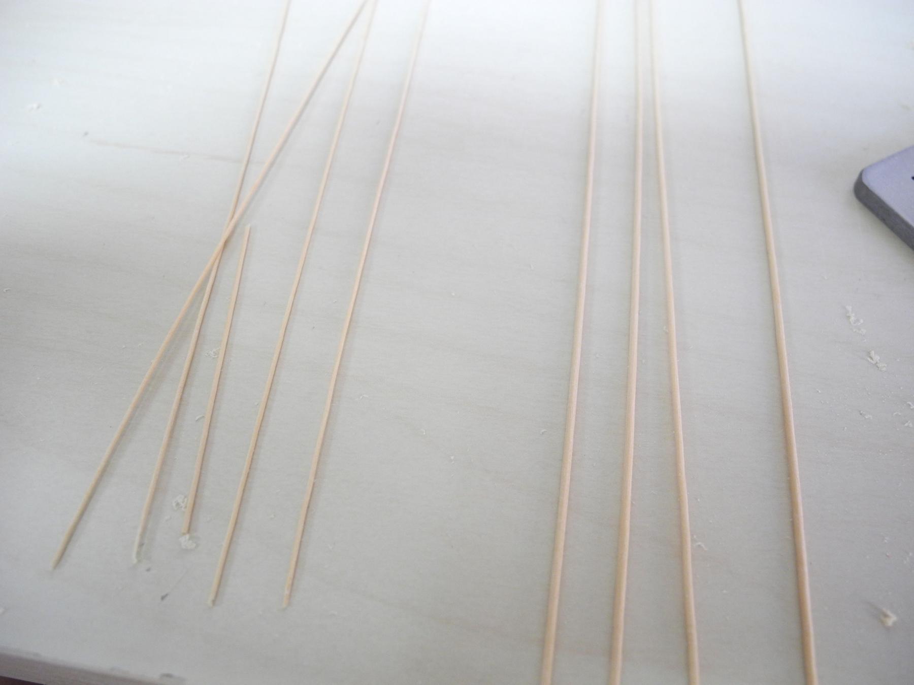
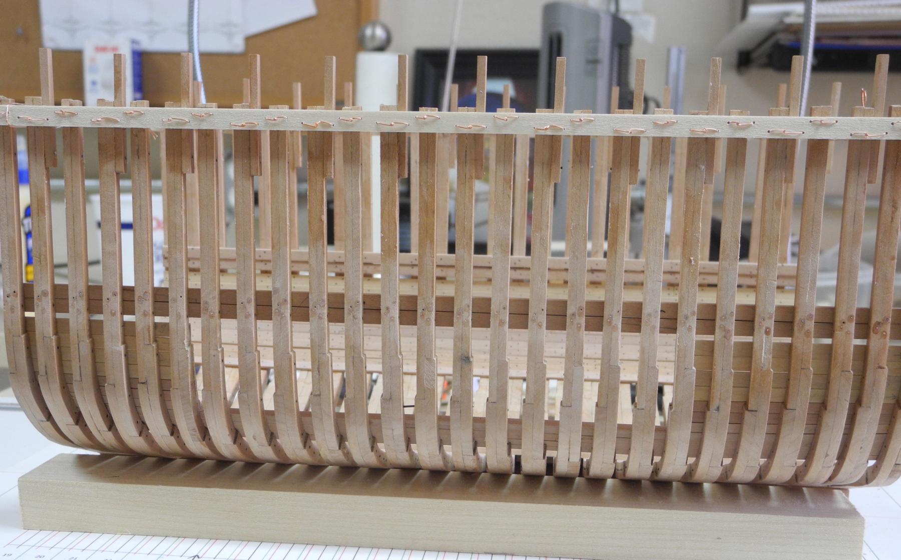
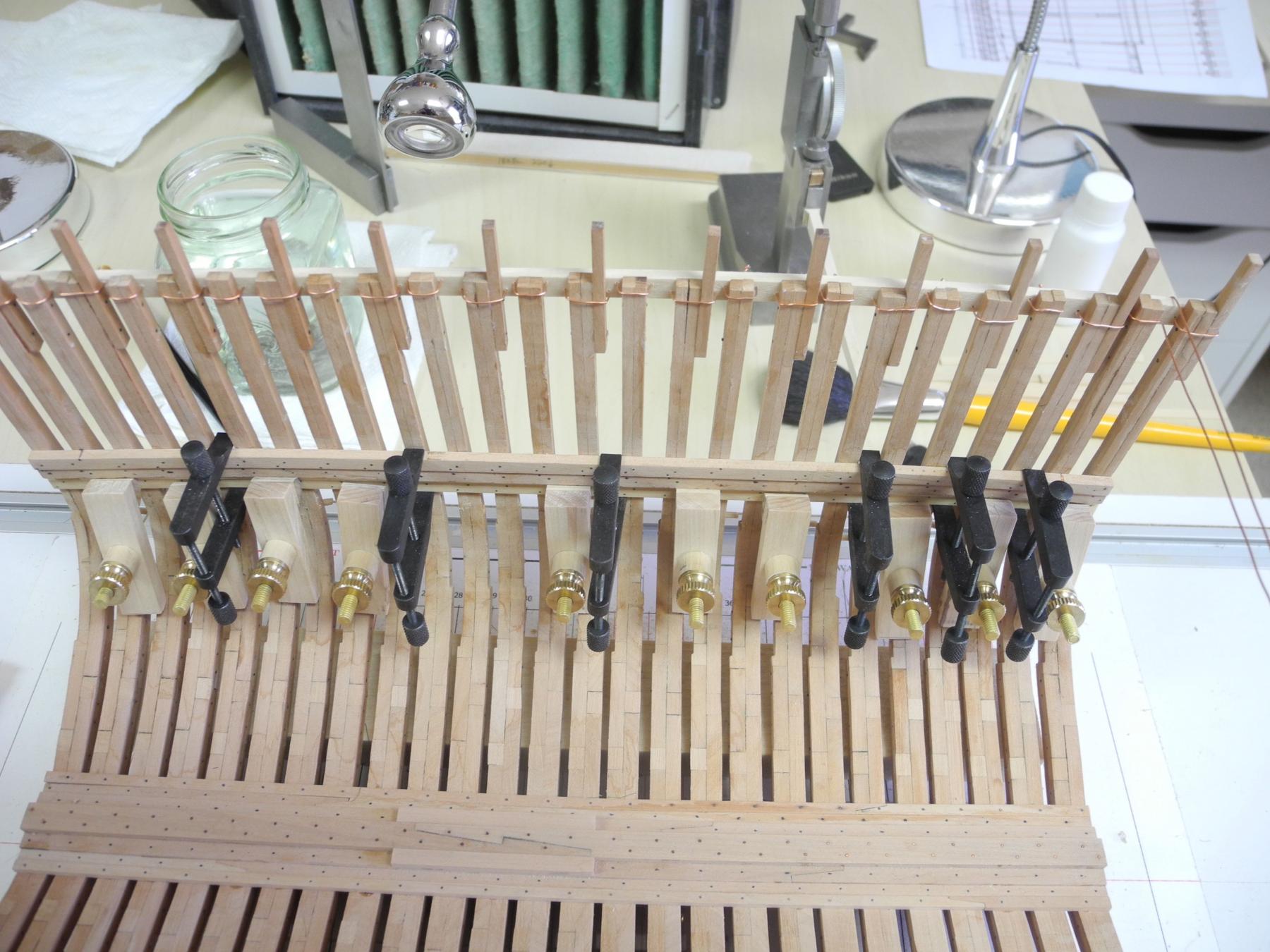
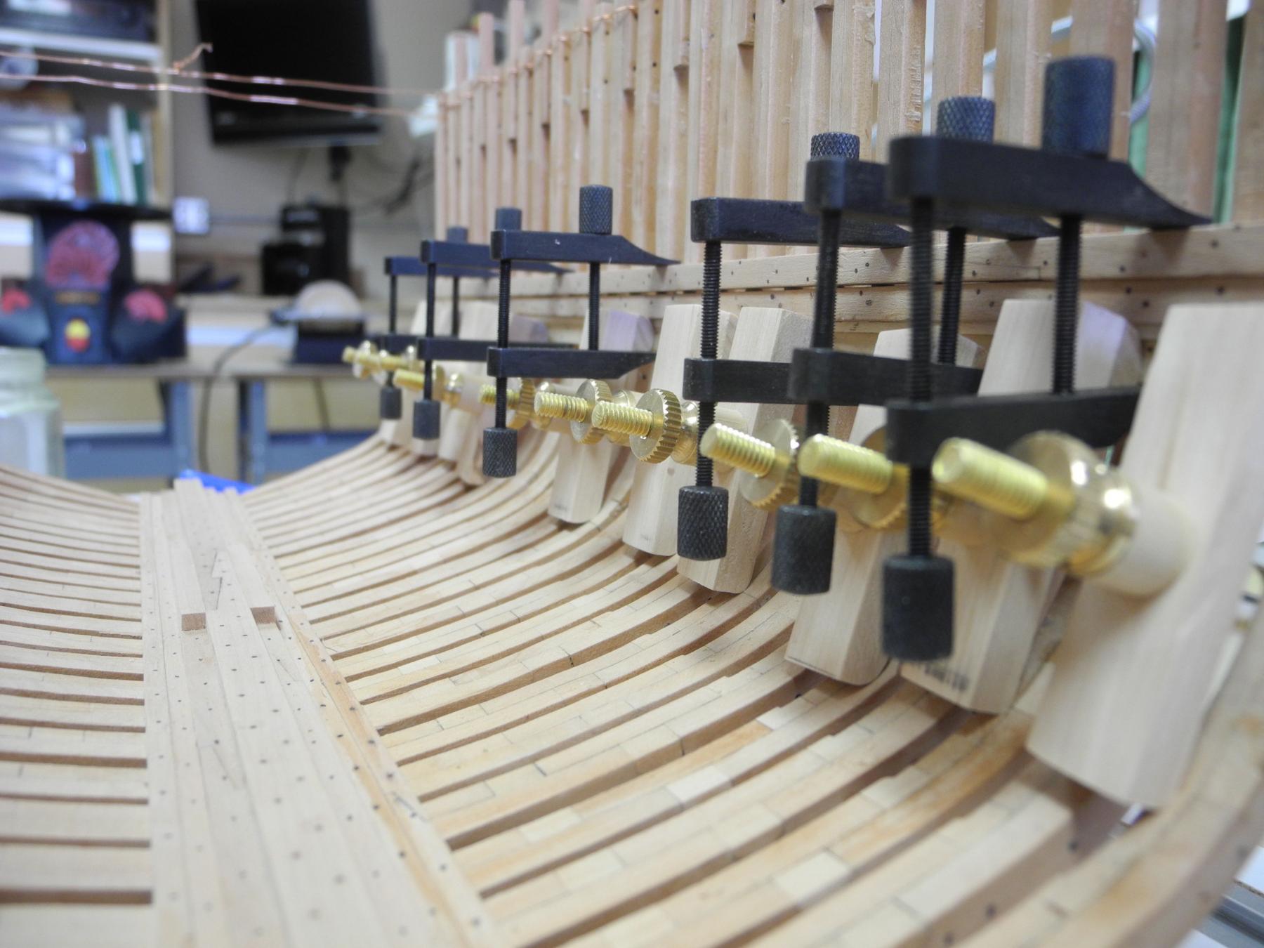
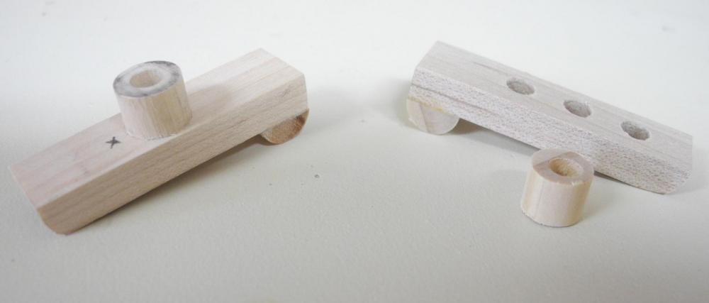
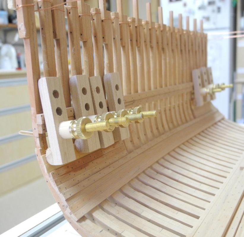
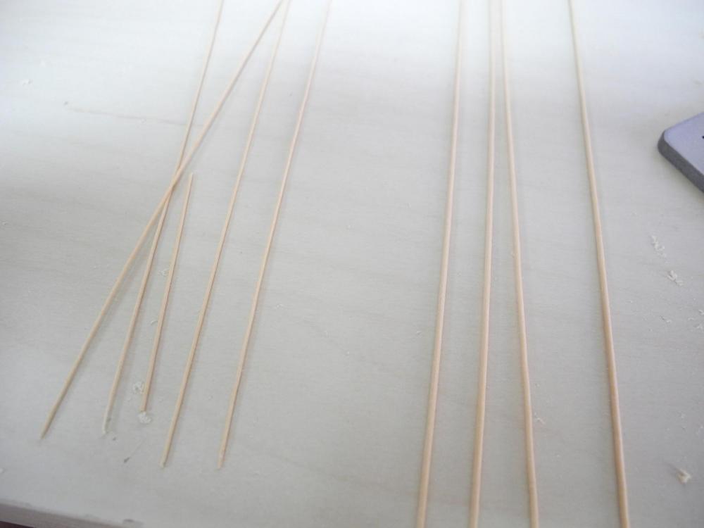
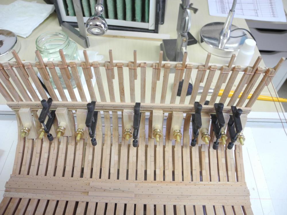
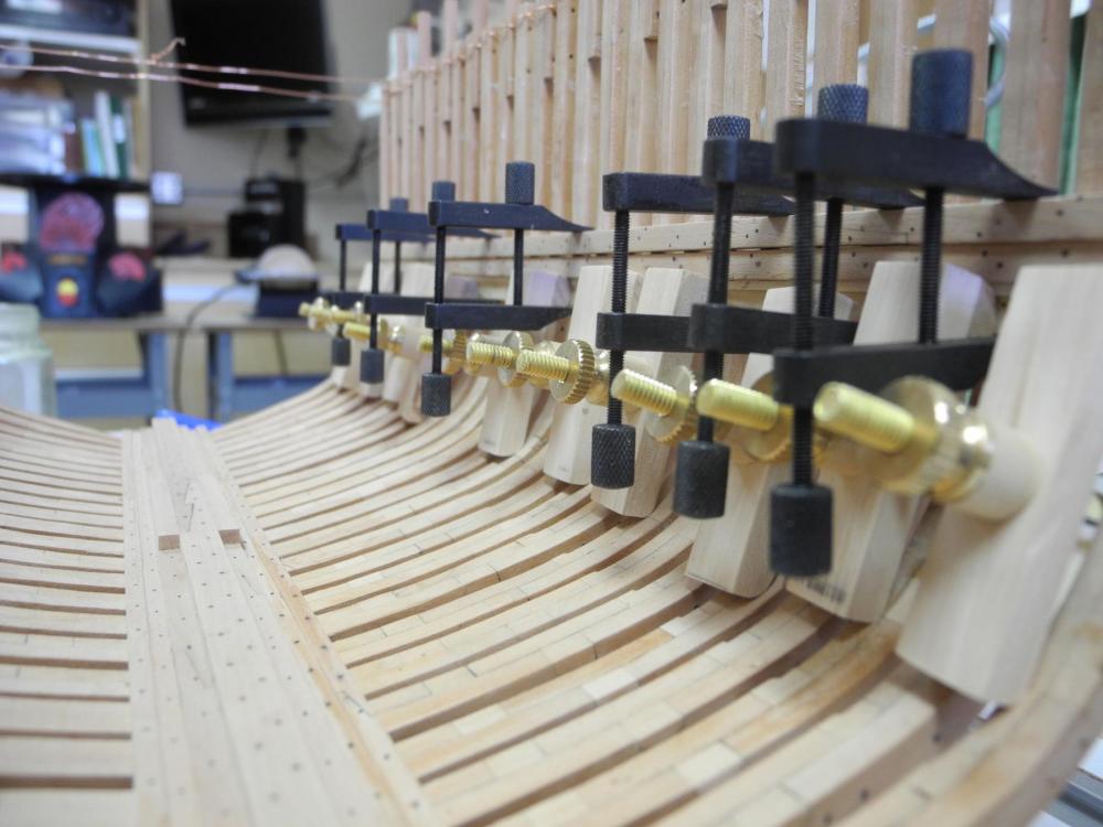
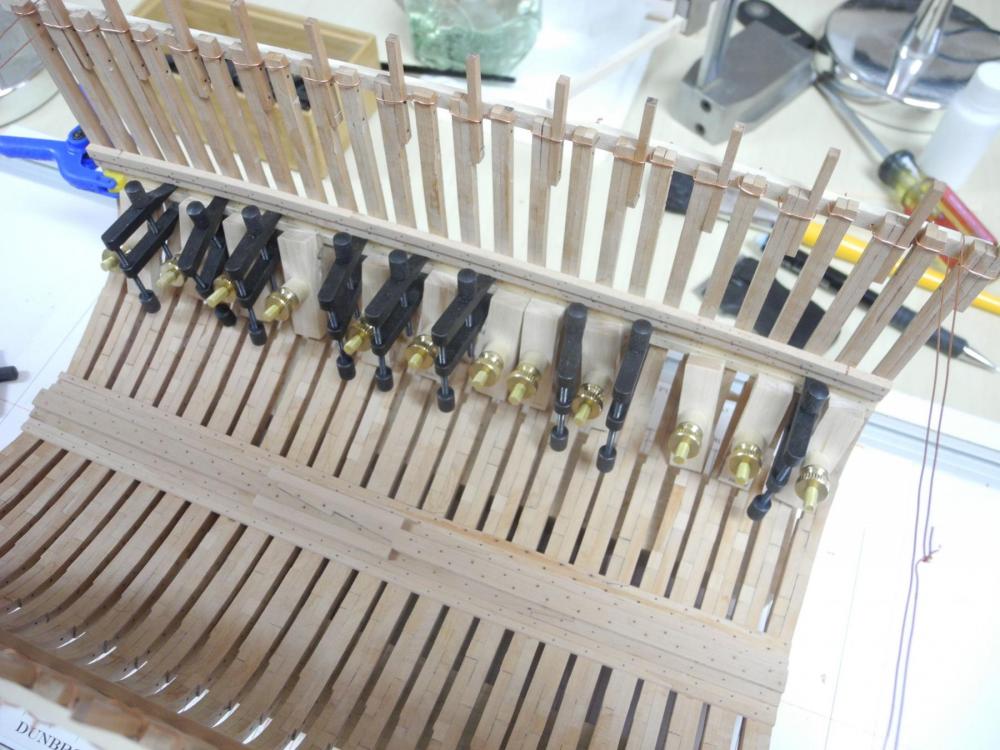
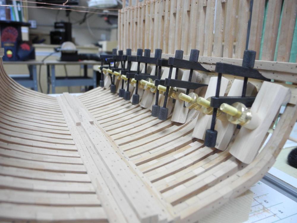
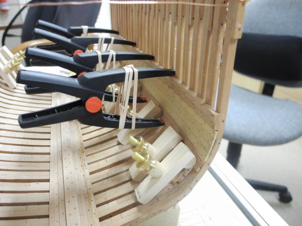
Lessons Learned Planking Clamps I’ve decided that I will leave the starboard exterior mostly unplanked so the frames can be seen. I’ve already decided to try to use LED’s to provide more lighting in the hold and the Accommodation Deck. These two factors made me look a little more critically at the interior planking on the starboard side. I originally planned on the starboard side being almost fully planked, and any errors on the inboard planking on the starboard side wouldn’t be very visible. The bilge ceiling planks aren’t installed very well - there are obvious gaps between some of the planks. These gaps will be very visible from the exterior of the ship when the interior is lit by LED’s. So these planks needed to be removed (more alcohol!!) and reinstalled. When I started to install them I realized I had made an error when I made the planking clamps: I had glued the spacers to the top of the clamps – this gave me no flexibility in positioning the tensioning part of the clamp. I needed this flexibility because of the way the bilge ceiling clamps now had to be installed (working from the bottom up, rather than top down as originally done). My existing clamps could not be used for this reinstallation. So I made new clamp bodies, each with three different hole locations and with a non-fixed spacer. In the following photo the old clamp body is on the left and the new version with the separate spacer is on the right. These new clamps worked well. The following photo is of the clamps being used in a very close position – using the closest setting. When I reached the next plank up, this short position could no longer be used. I moved the tensioning rod to the middle, and needed to use a piece of wood behind the clamp to allow it to work. You can see what looks like a timber above the deck clamp/shelf combination in the photo – this is simply a loose piece of stock to allow the clamp to tension properly. I’m very happy with the new planking clamps, even though they won’t get much more use in this build. Making Treenails I’ve also decided that the floor ceiling planks and any exterior planks will need to be pinned in place for glueing, as Ed has done in the Young America build. The holes used for pinning would need to be filled with bolts or treenails. I’ll be using treenails for two main reasons: 1. It’s more accurate – treenails were more often used on the planking, while bolts were used on the structural timbers. 2. It’s easier to clean up. Using treenails will allow me to use PVA glue, which can be cleaned up with water, while using bolts would make me deal with cleaning CA or Epoxy residue – neither is a good choice for me. I’ve played with making treenails in the past and have been very frustrated with the experience – mostly using bamboo skewers. I decided to try using the same color wood as the planks (castello) so that the treenails would be more subtle. I had some Pau Marfim (also known as Guatambo) scraps, so I decided to use them – they look very much like castello and are almost as hard. I started by milling the scraps down to a little under 1/32 square, about 8 inches long. In previous attempts at making treenails, I had basically pulled the wood through the Byrnes drawplate with a pair of pliers, and went from one hole to the next in each step. The pliers crushed the wood and the tension I needed to apply to the wood broke more pieces than I produced. In this process I pulled the wood through with my fingers, and continued pulling through a hole until no more wood shaved off (4 to six times at each hole). This made the subsequent smaller hole much easier to navigate. I was able to get down to .030 inch pretty easily, and thought this would be a good size to stop at (2 inches at scale). Wrong! I checked the Crothers book for treenail sizes, and found that I should be aiming for 1.25 inches or less – around .021 to .024. This was much harder to get to. The treenail stock was now so thin that any accidental pressure would break them, and it was much harder to get them started in the holes. I was able to produce some decent treenail stock in the correct sizes, and I’m sure with more practice I’ll improve. The correct treenails are on the left in the following photo. All told not too much progress in building the model since the last post, but good progress in improving my modeling skills. Thanks everyone!


- 649 replies
-
- 20
-
-
- dunbrody
- famine ship
- (and 2 more)
-
Hi Ed - the intellectual challenge is one of the things I love about this hobby. My other hobby - bird carving - is more of an artistic challenge. I was thinking of leaving the frames associated with beams so that the knees would be visible in the viewing ports. Maybe I'll just do that in the lower viewing port and leave the one for the Accommodation Deck completely open. I guess this is something that can be decided on later.
- 649 replies
-
- 7
-
-
- dunbrody
- famine ship
- (and 2 more)
-
Thanks Patrick - I always value your opinion. I am going to leave some of the framing exposed, but there are some areas I may want to cover if I can't clean them up. Welcome aboard Gerhard.
- 649 replies
-
- 5
-
-
- dunbrody
- famine ship
- (and 2 more)
-
Hey Alan - I'm a student too, never having done anything like this before. I'm still trying to figure out a lot of things - what planking to leave off is only one of them.
- 649 replies
-
- 5
-
-
- dunbrody
- famine ship
- (and 2 more)
-
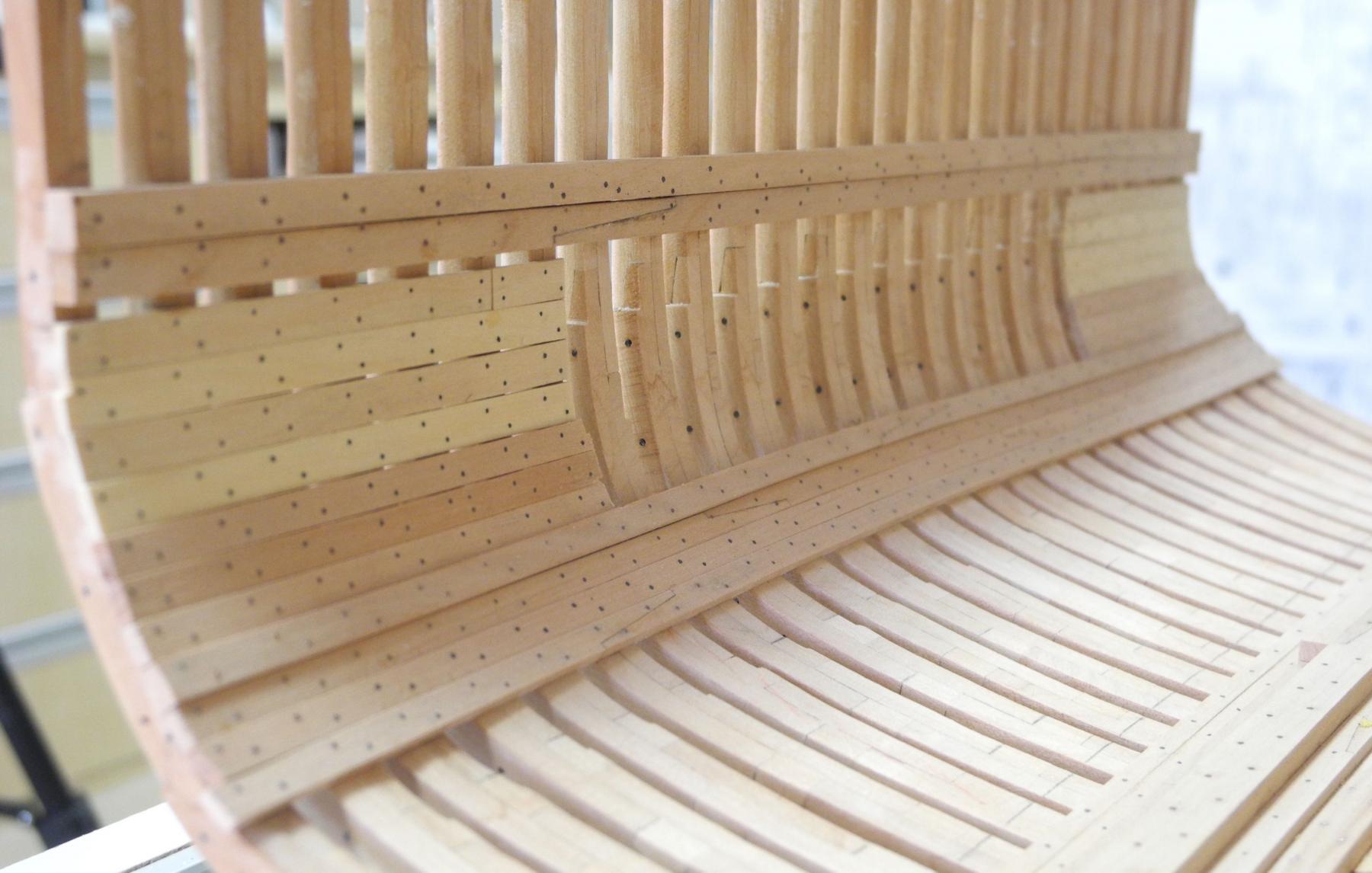
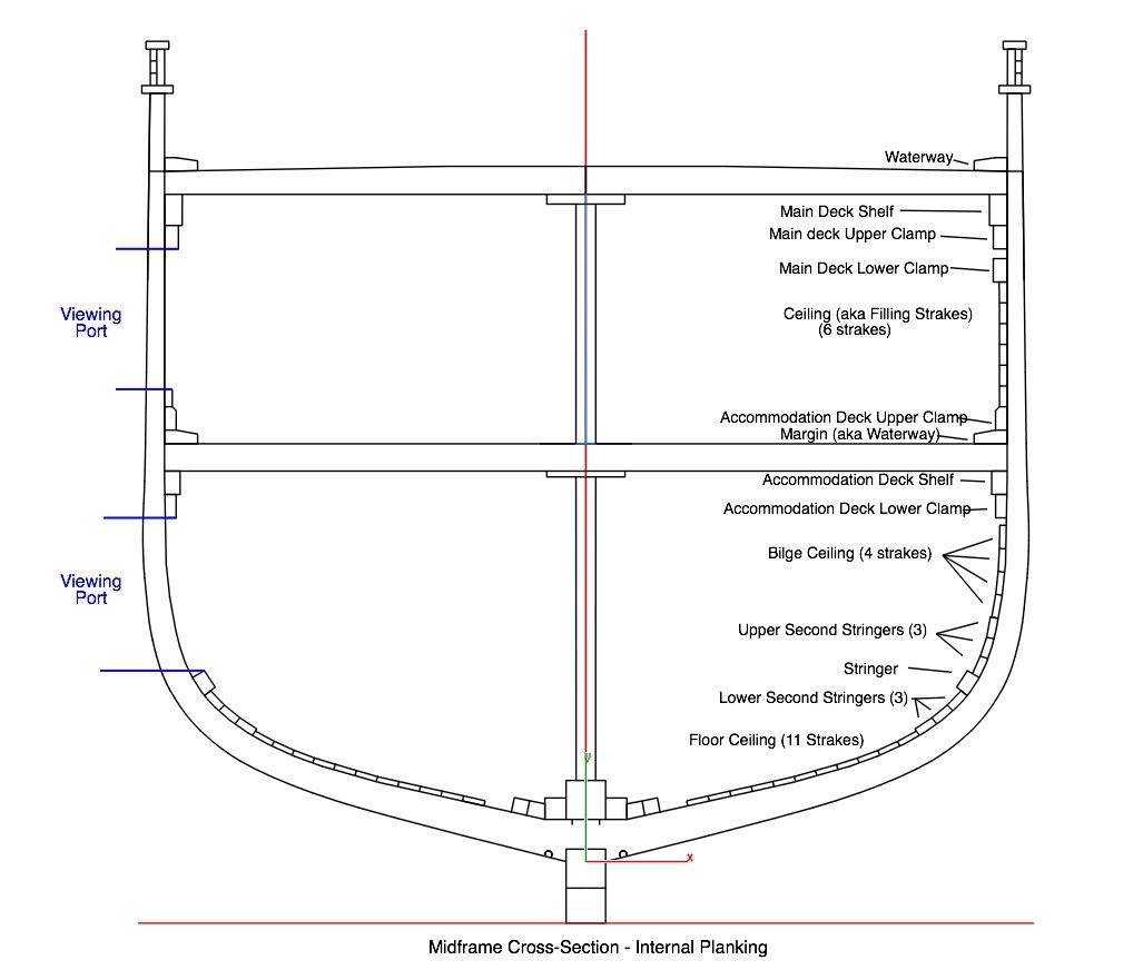
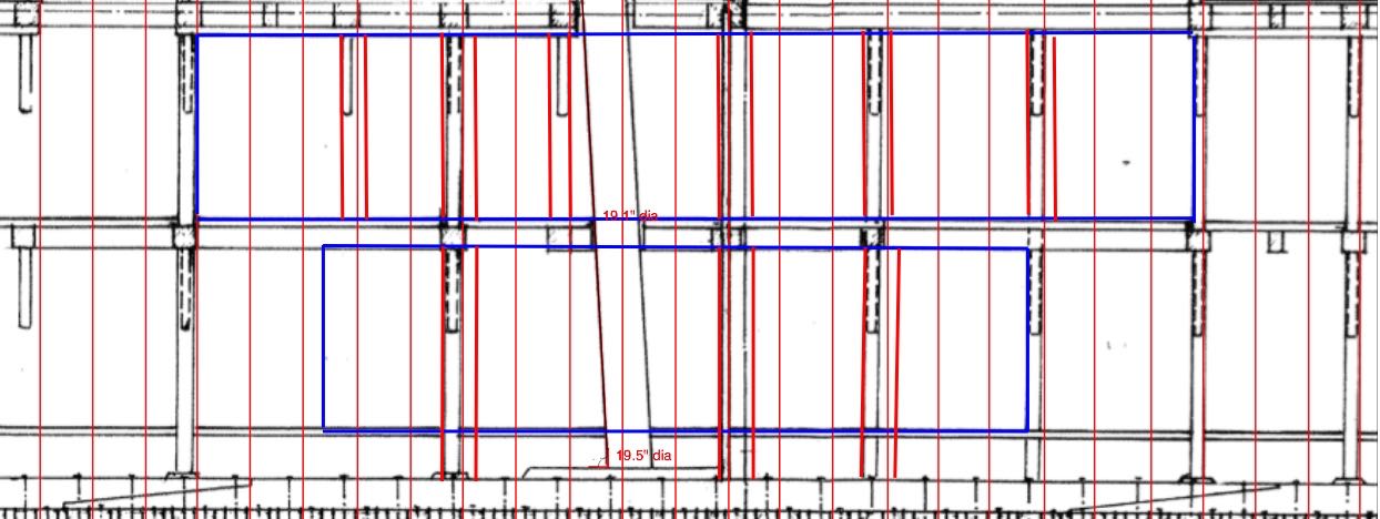
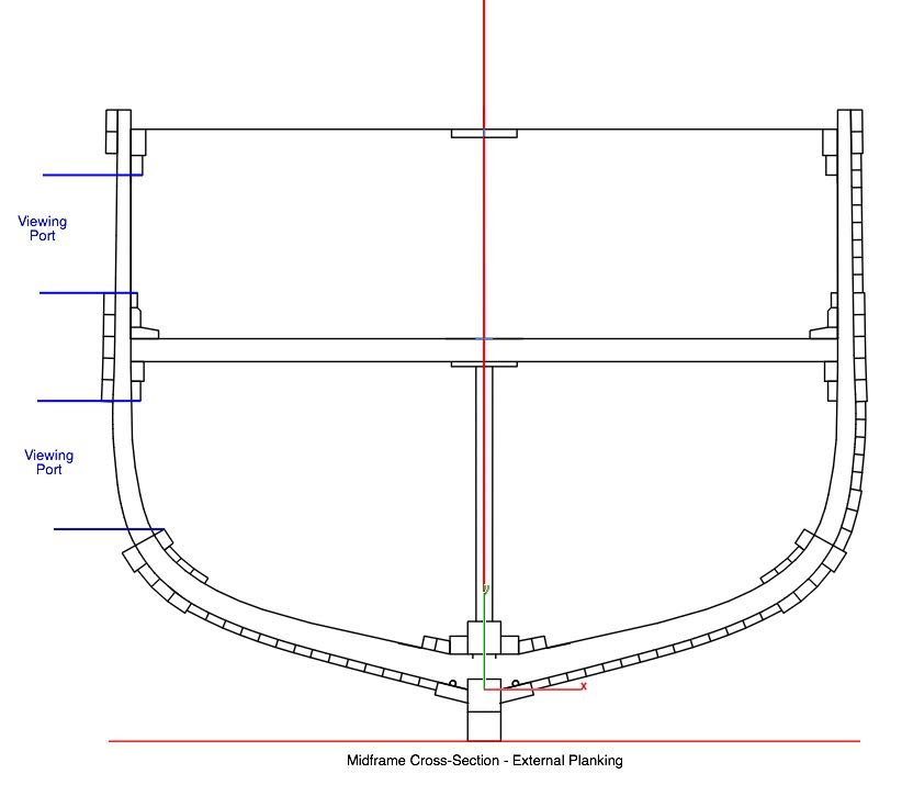
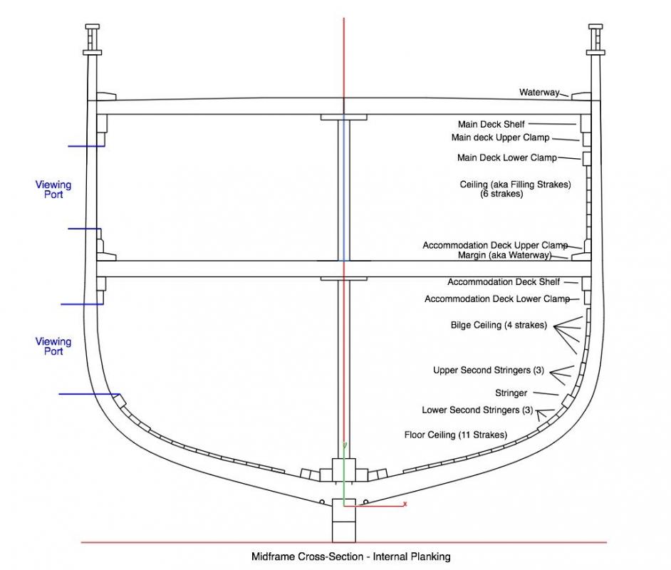
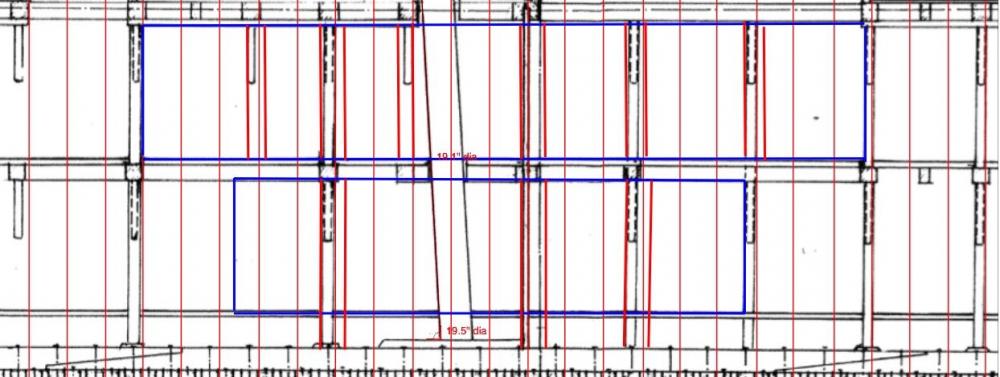
Part 22 – Viewing Ports Installation of all of the Hold Timbers is completed. The next step is to install the 22 strakes (11 each side) of Floor Ceiling. I’ve already milled the castello for these planks, but I’m mulling over the best way to install them. Because of the narrowing of the hull towards the fore and aft ends of the model, I’ll need to install some drop planks at certain points. I need to do a little studying and planning to pull this off. Ed’s Young America book will help in this regard. While installing the Hold Timbers I left an opening where the Viewing Port for the hold will be. You can see the interrupted strakes on the starboard side in the above photos. The following photo is an external view of the starboard side. I installed only partial strakes of the Bilge Ceiling, leaving the viewing port area open. Even though the top three Second Stringers would also be partial I installed full strakes so that the stringer would align properly. After all of the timbers were installed I cut out the middle portions of the second stringers. The following photo is a drawing of the midship frame, showing the arrangement of internal timbers and planking around the viewing ports. The lower Second Stringers have been installed as full timbers on the starboard side, and I’m trying to decide whether or not to install all of the floor ceiling on that side as well. I may leave some of the strakes off to show the framing. The next photo is a drawing of the same area, showing the arrangement of external planking around the viewing ports. The Port side of the model will be completely planked. I haven’t decided on the planking for the starboard side yet. I could plank everything except the area of the view ports, or I could decide to leave more of the planking off to show more of the frames. I’m leaning towards the latter, since a lot of work went into those frames. I will need to leave certain frames in place within the viewing ports. These are the frames that are associated with the deck beams on each deck. The following drawing shows the view ports outlined in blue and the frames that will be left intact in red. As you can see, there is one frame that will be open in the hold but the upper part of the frame will be left intact in the accommodation deck area. This frame supports a beam that is under the windlass on the main deck. I don’t anticipate an issue with cutting away the lower portion of this frame – that won’t be done until all of the supporting timbers and most of the planking is in place. I’m open to (and would welcome) suggestions on how to configure internal and external planking to make best use of the viewing ports. Thanks everyone!

- 649 replies
-
- 21
-
-
- dunbrody
- famine ship
- (and 2 more)
-
I'm always amazed at how much detail you can pack into a tiny space. Looks great, Patrick.
-
Looks like a very nice job on the fairing, Brian.
-
Thanks Ed, and especially thanks for the warning. I hadn't thought of that and probably would have learned the hard way.
- 649 replies
-
- 4
-
-
- dunbrody
- famine ship
- (and 2 more)
-
Thanks Patrick! Can't have too many clamps. Glad you're enjoying it - as I enjoy your work.
- 649 replies
-
- 4
-
-
- dunbrody
- famine ship
- (and 2 more)
-
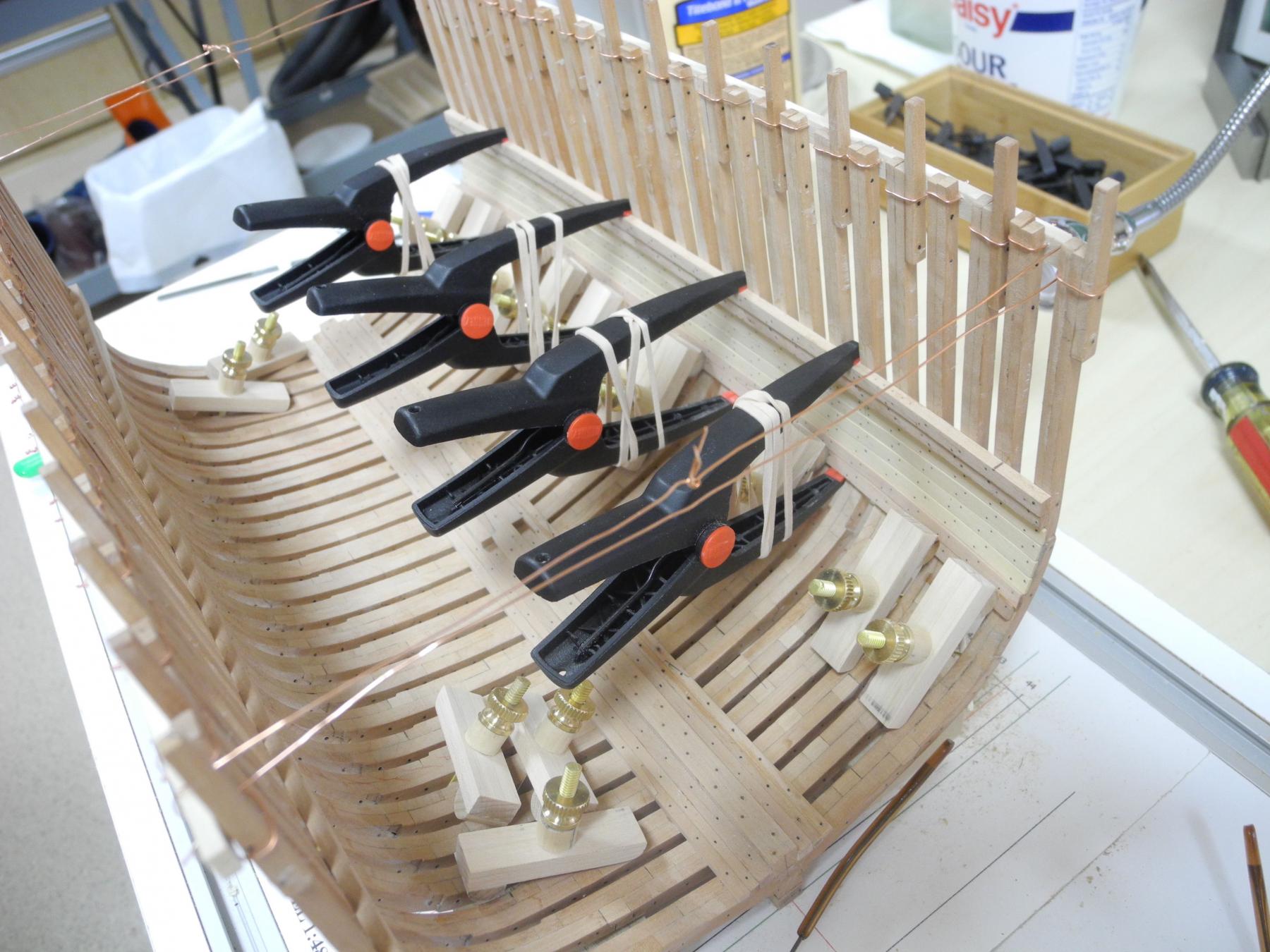
Part 21 – The Hold Timbers cont’d The reason I removed the Bilge Ceiling planks is that there were some spaces between some of the planks. When I clamped the planks to the frames I only used the planking clamps, assuming that these clamps would keep enough upward pressure on the planks so that they would lie securely against the plank laid previously. This proved to be incorrect – there were fairly obvious spaces between the planks. There was also a strake that wasn’t properly secured and lay proud of the other strakes. On the second installation I spent considerably more time getting the clamping set up – I tested the setup for each strake before applying glue. I also used my small machinist screw clamps to keep the new plank pressed against the previously installed plank, in addition to using the planking clamps which provided pressure against the frames. On the first two strakes I clamped against the deck shelf with the screw clamps. On subsequent planks the machinist clamps are too small to reach from the shelf to the bottom of the lower two strakes, so I clamped them to the top of the first bilge ceiling strake, since these clamps are small enough for the nose of the clamp to fit into the air strake above it. After the 4 strakes of bilge ceiling were installed I moved on to the “second stringers”. Again the machinist screw clamps were too small to reach any area that could be used for clamping, so I needed another clamping approach. I have some Bessey 2” Clippix needle nose spring clamps that will reach from the Stringer to the shelf, but I thought the tension wasn’t strong enough to properly pull the clamps together. I wrapped a strong rubber band around the clamp jaws and this improved the tension enough to do the job. Each of the stringers needs to be soaked and bent prior to installation, so this work is in progress. While waiting for the stringers to dry I am also planking the starboard side. I’m leaving the gap for the viewing port, and will address this in the next post. Thanks everyone!

- 649 replies
-
- 22
-
-
- dunbrody
- famine ship
- (and 2 more)
-
Hi Tim Thanks for sharing the amazing story of the Stephen Hopkins. I remember as a kid driving along the Hudson River and seeing rows and rows of the liberty ships a few years after the war. I think at the time they were being used to store surplus grain. I'll be following your interesting build.
- 227 replies
-
- 3
-
-
- BlueJacket Shipcrafters
- Stephen Hopkins
- (and 2 more)