Mahuna
-
Posts
1,504 -
Joined
-
Last visited
Content Type
Profiles
Forums
Gallery
Events
Everything posted by Mahuna
-
 Hi Patrick. Shadow already looks like it will be another Omega masterpiece. I'm going to enjoy the journey.
 -
Thanks Patrick. A closer look shows a lot of room for improvement, but overall I'm pretty happy with the results. I guess each of us is always most critical of our own work. One of my goals in this build was to see if I could improve my accuracy in the details - I keep trying. Thanks Bob. Dunbrody will look fine in my museum (den), but I don't think it would stack up well to real museum models. But I do appreciate your comments.
- 649 replies
-
- 4
-

-
- dunbrody
- famine ship
- (and 2 more)
-
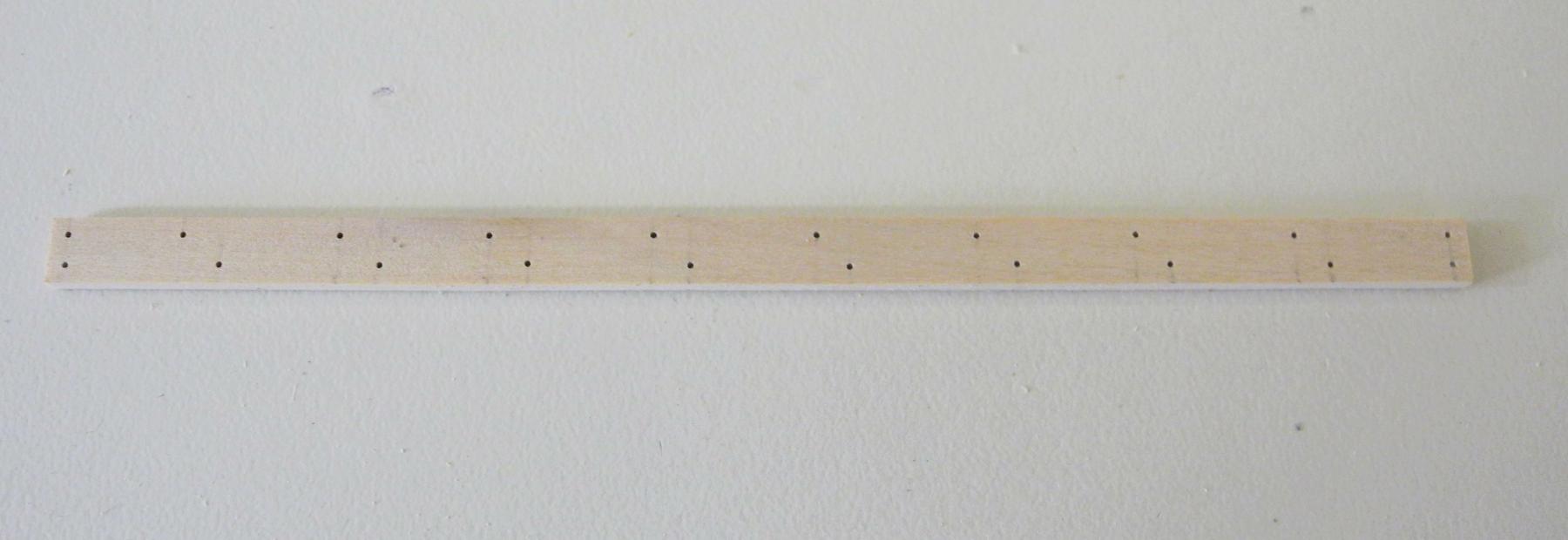
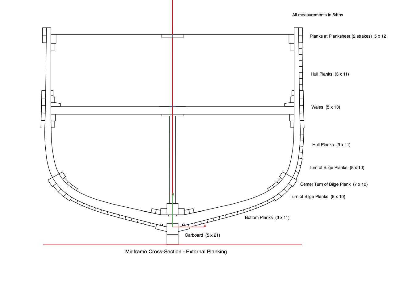
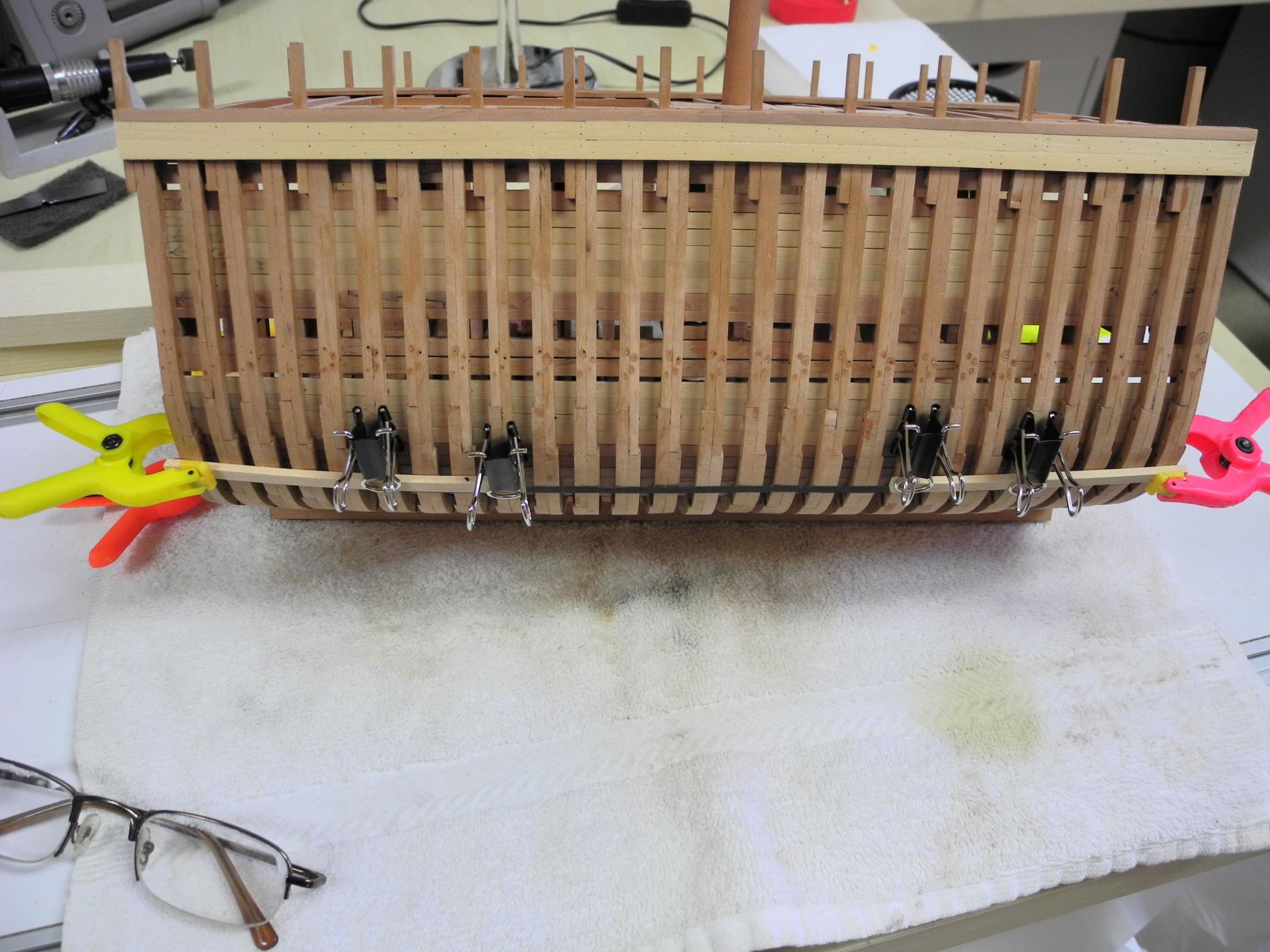
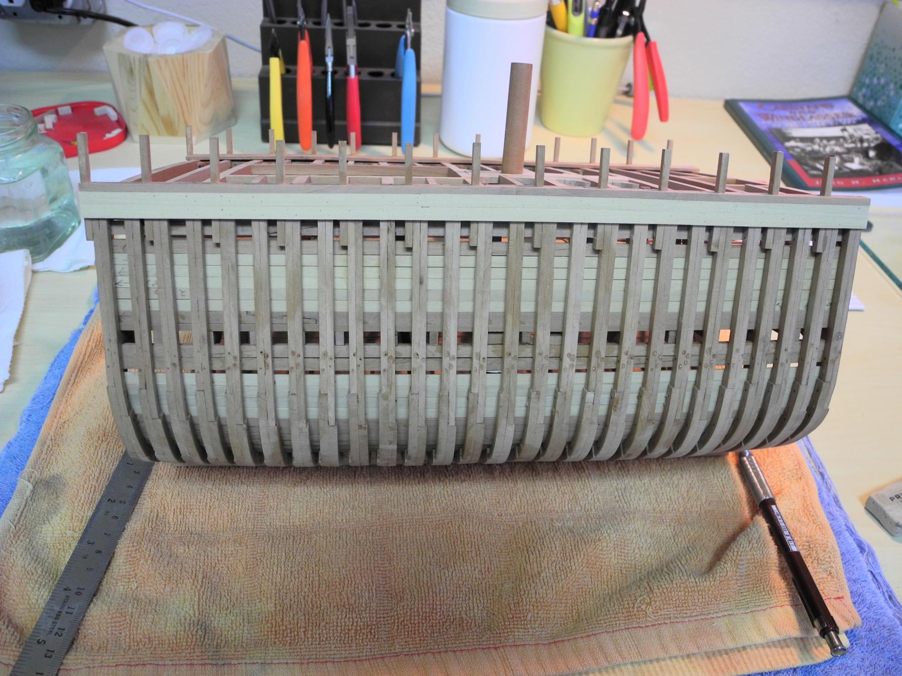
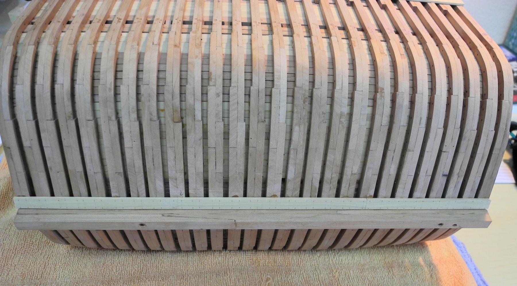
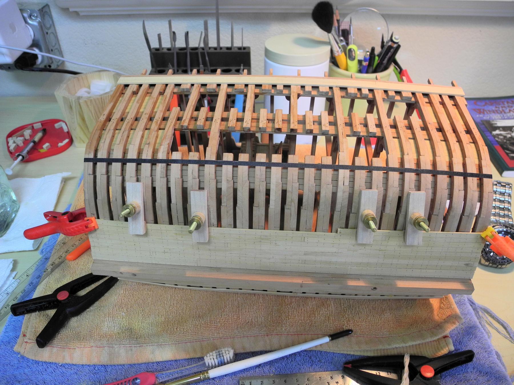
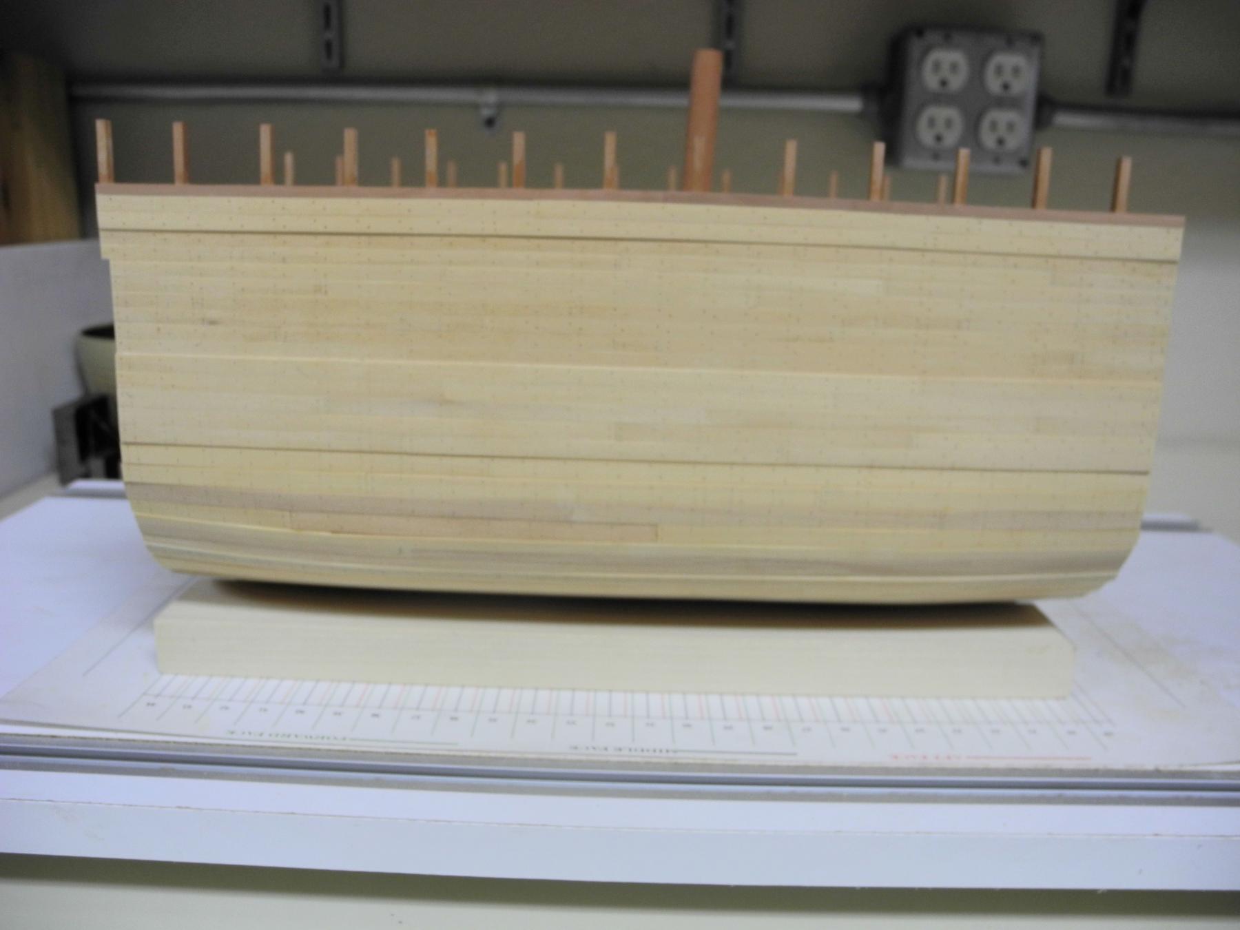
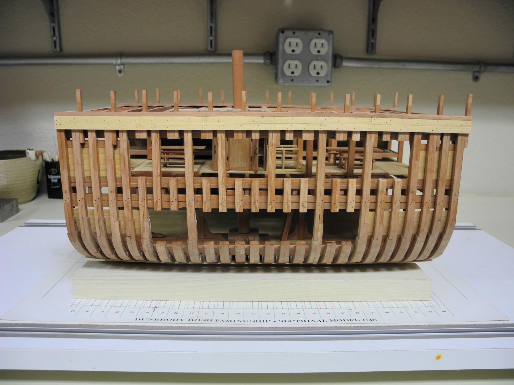
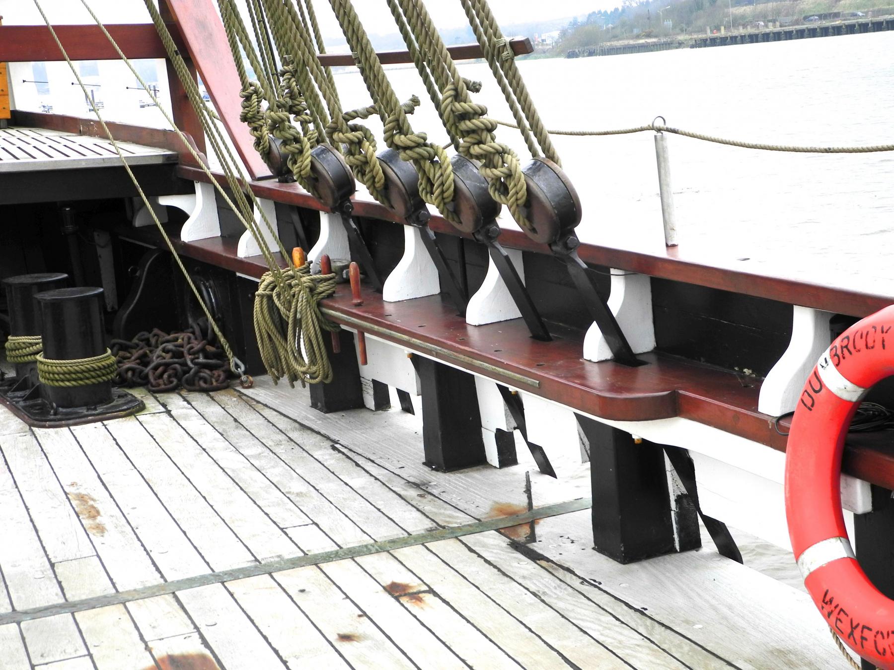
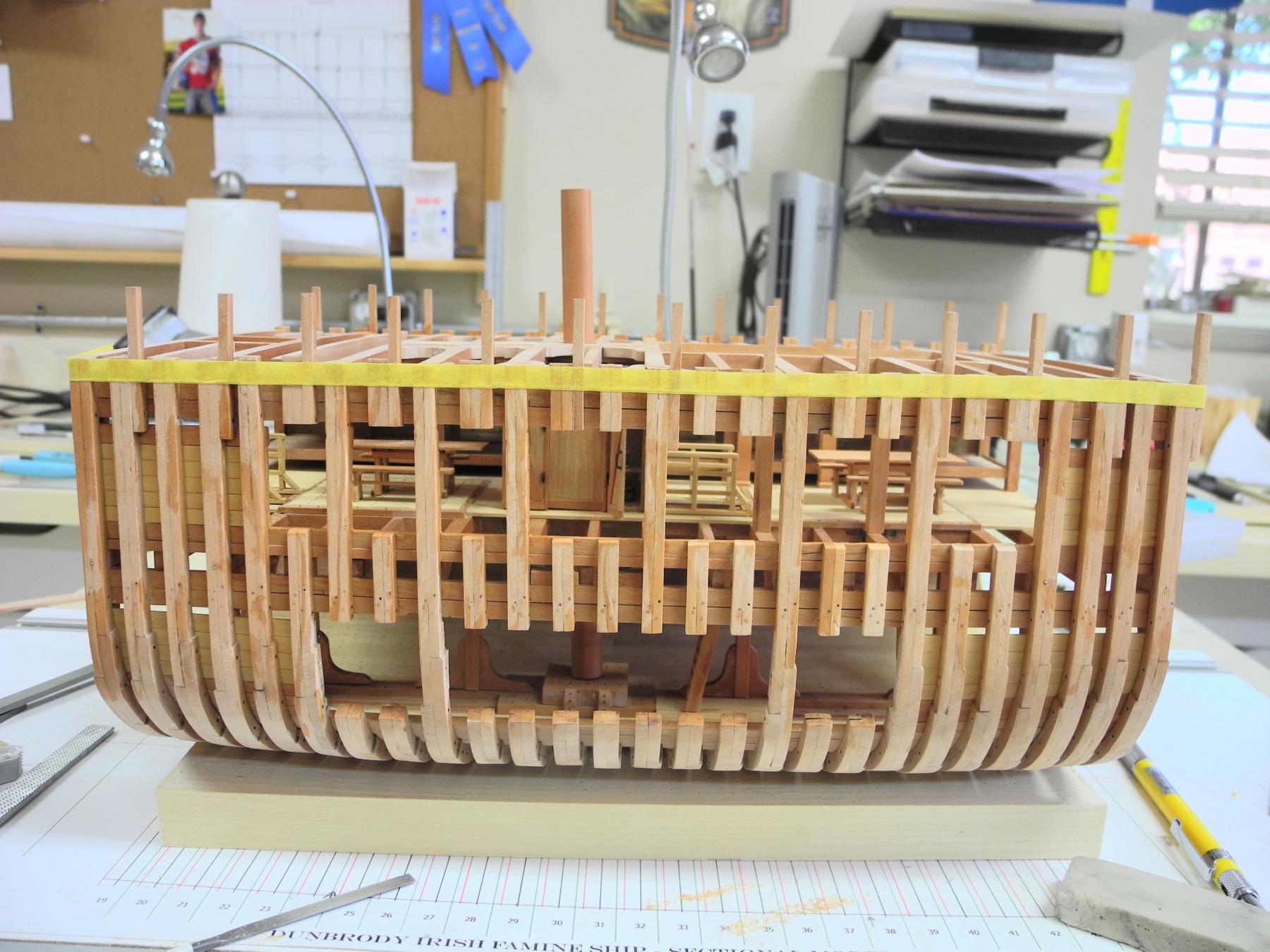
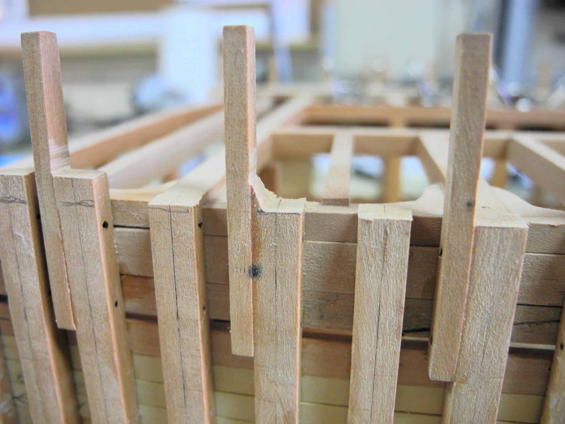
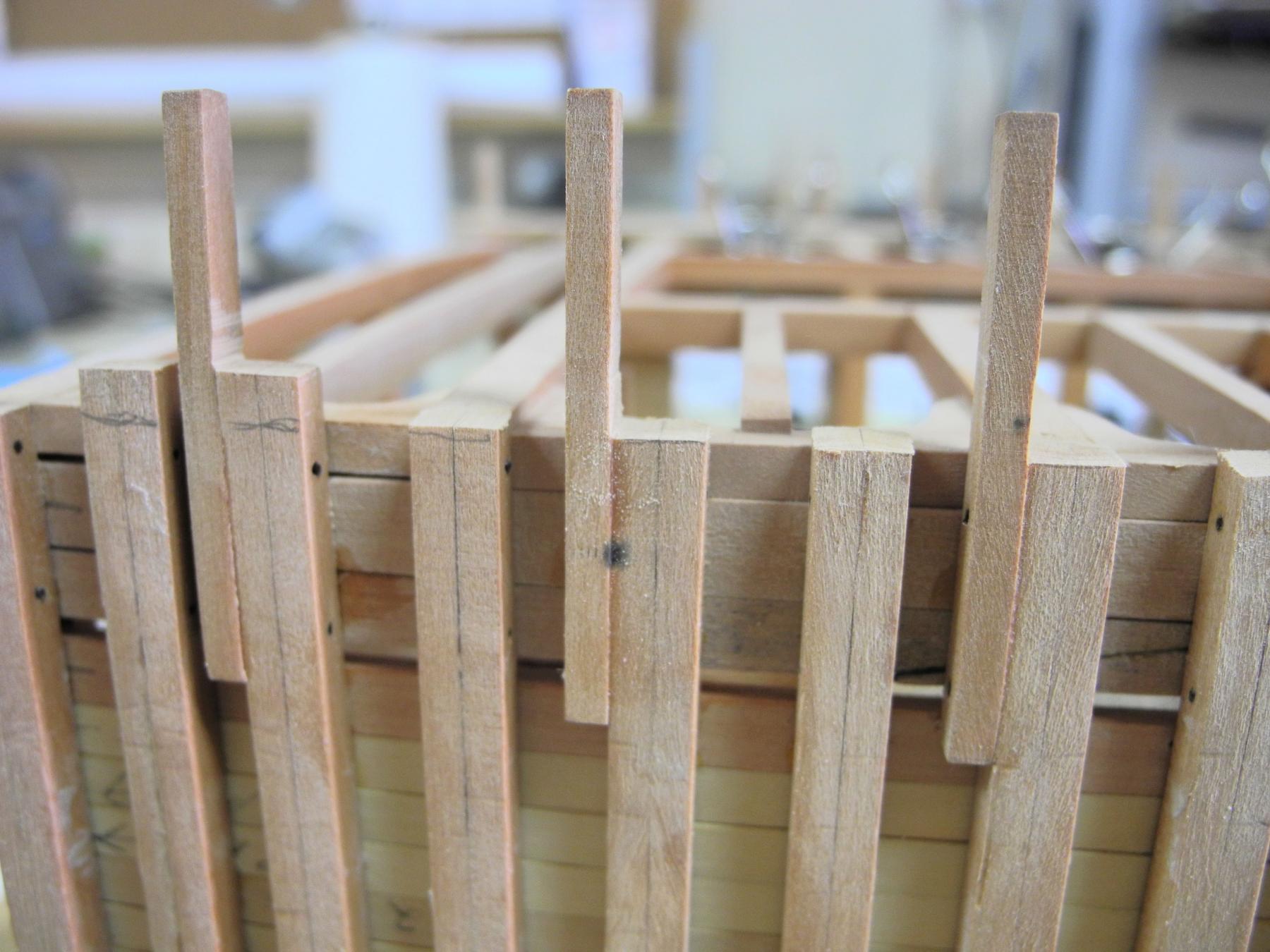
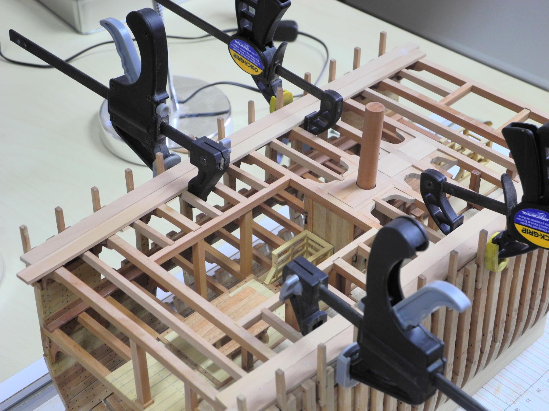
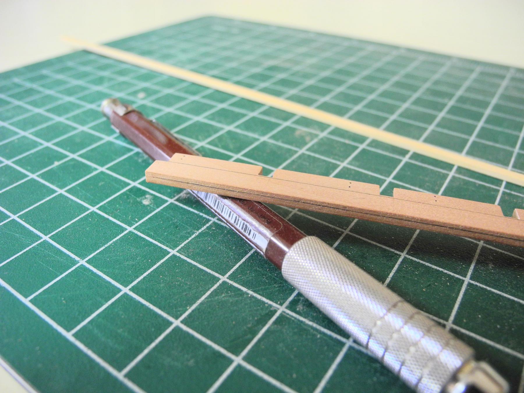
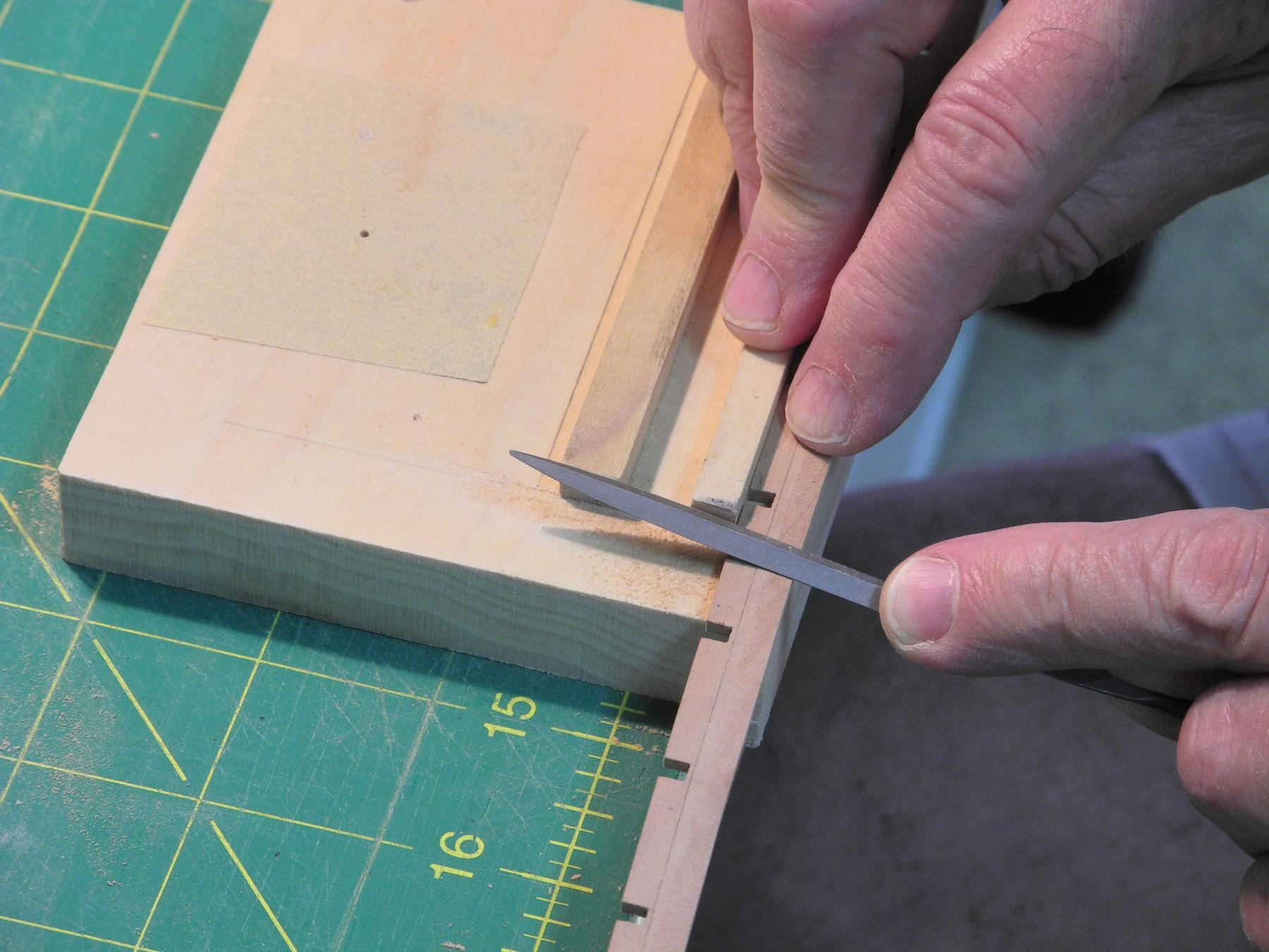
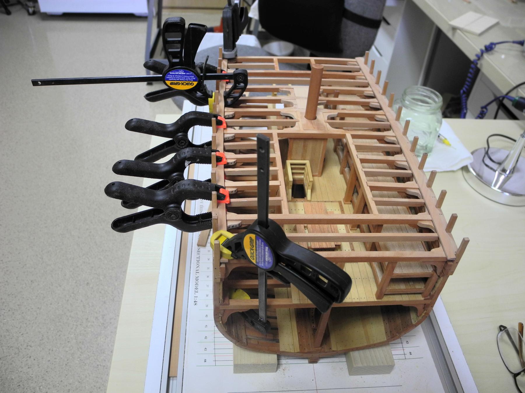
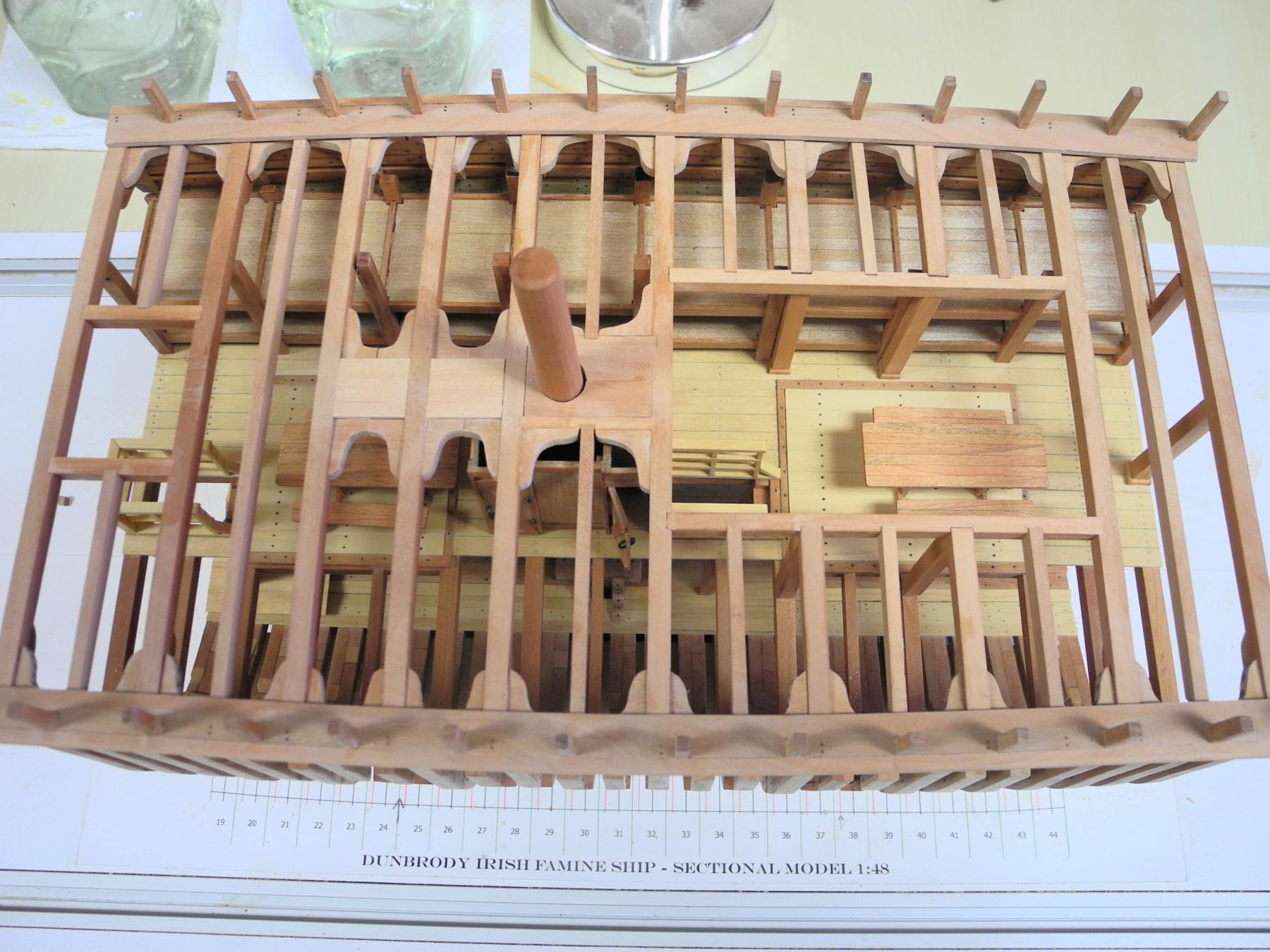
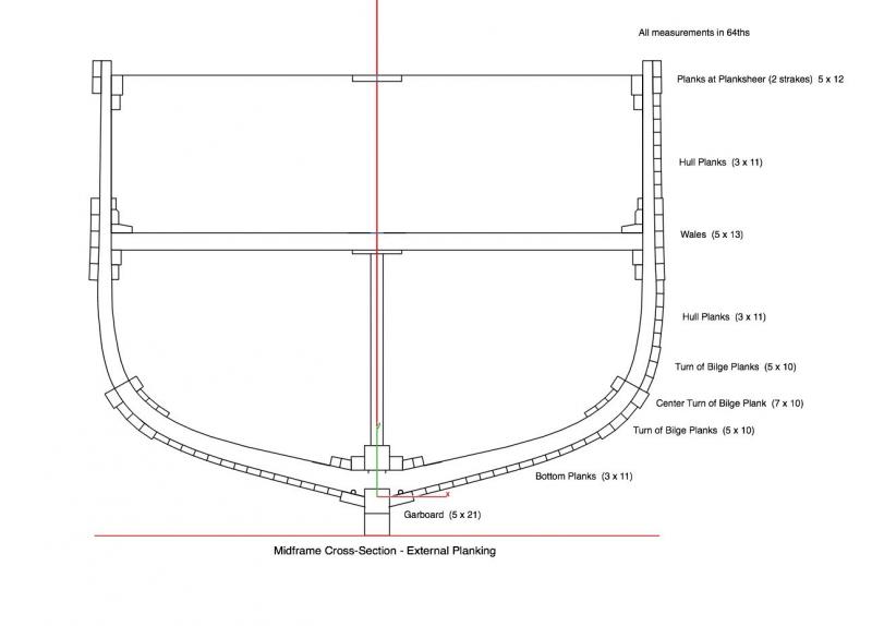
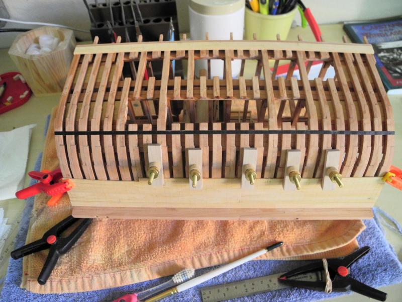
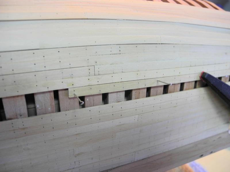
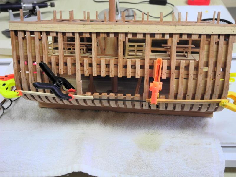
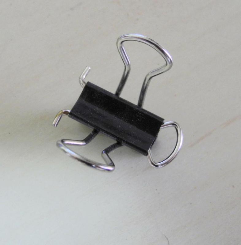
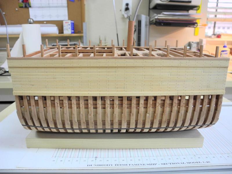
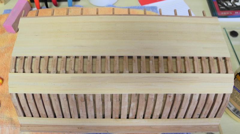
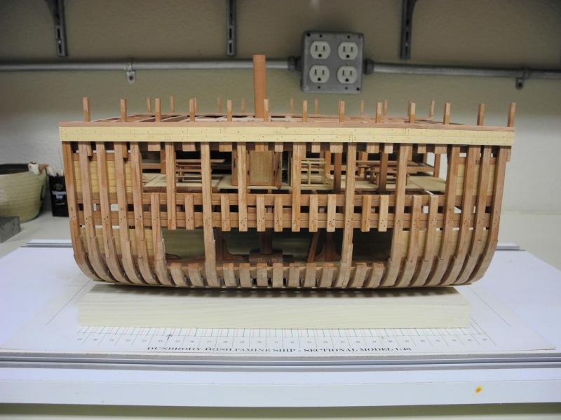
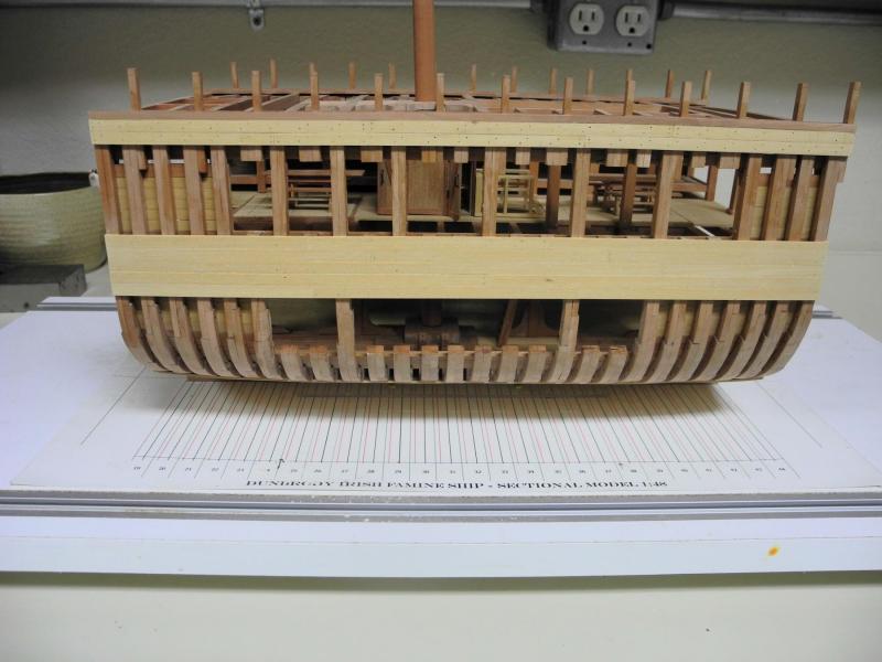
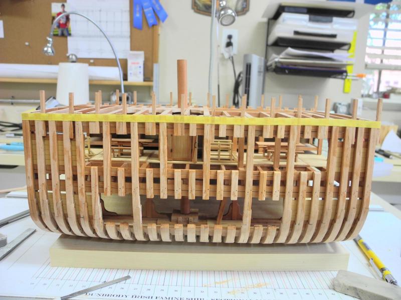
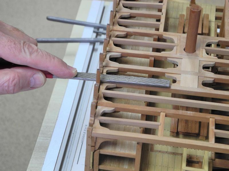
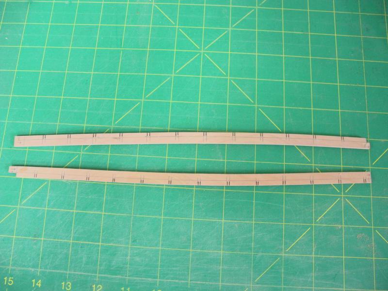
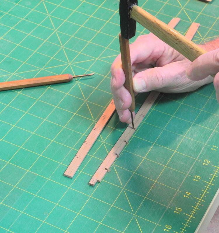
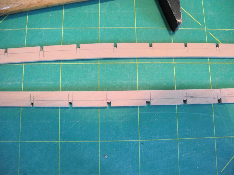
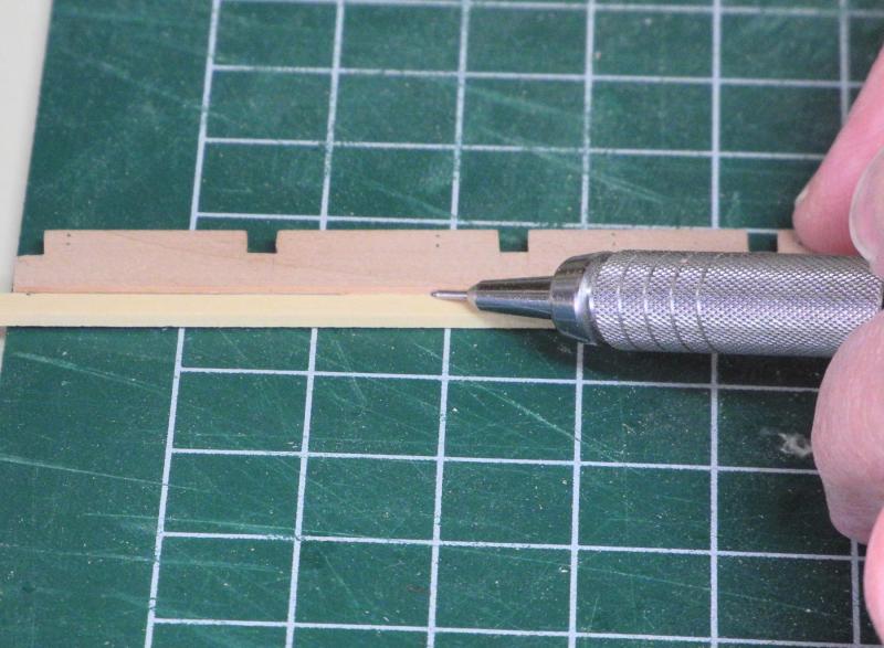
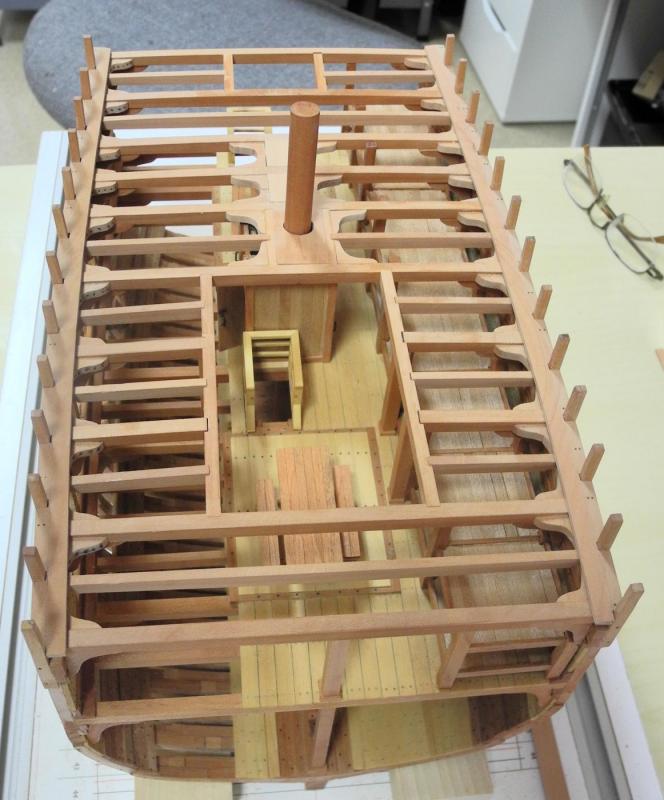
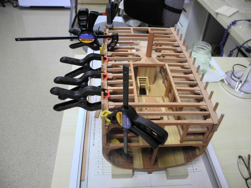
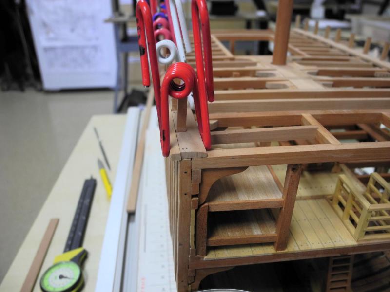
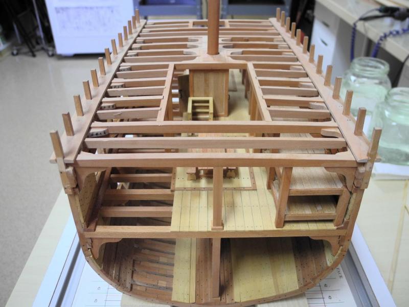
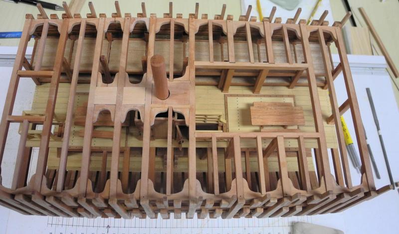
Part 43 – Exterior Planking It has been a while since my last update. Work on Dunbrody was interrupted several times for some personal business – family travel and such – but I’ve managed to make some headway on the exterior planking. Dunbrody’s exterior planks are of different widths, depending on the location of the planks. The following drawing shows the dimensions of the planks in 64ths. These measurements were taken from the cross-section on the construction plan. Based on photos of Dunbrody, the planks that can be seen above the waterline show distinct differences in thickness, so all planks were left at their measured thicknesses rather than trying to blend these thicknesses into a smooth side. This also serves to break up the appearance of the fully planked port side of the model. Without the varying thicknesses there would be no texture to the model, since it is not painted. The actual replica ship has fake gunports breaking up the black sides, and there is a green anti-fouling paint visible at the waterline – none of this is present on the model. As with the ceiling planks shown in a prior post, all exterior planks were cut to size and pre-drilled for treenails prior to installation. Various methods of clamping were used to secure the planks while the glue dried, depending on access to frames for clamping. The last photo above shows binding clips being used as clamps. These clips were modified as shown in the following photo (this idea came from a build log I saw some time ago – I don’t remember the name of the log). Planking started with the two planks immediately below the planksheer/waterway. In the prior post, the waterway was shown with a rounded edge. When I started planning for the planking I realized that this was an error on my part – the molding is actually on a different location, and the waterway needs to be flush with the planks to allow the chainplates to lie flat against the ship’s side. So after installing the two strakes I reduced the rounded edge to be flush with the planks. The next planks to be installed were the garboard planks. The upper planks were installed next. These planks were followed by the wales, the first strake of which can be seen in the following photo. The planks at the turn of the bilge are located at the same height as the stringers inside the hull, and are fairly thick. The center strake is the thickest of all the exterior planks, and needed to be boiled and bent in sections as seen in the following photo. Black art tape was used to position this strake in a fair line. The bottom planks were then brought to the lower edge of the lowest strake at the turn of the bilge. And finally the planks between the wales and the turn of the bilge were installed. The following photo shows the completed port side. The starboard side has minimal exterior planking so that the details of the frames can be seen. Originally the plan was to install only the top two strakes and some of the bottom strakes, as seen in the following photo. During our recent club meeting, both Rich and Brian suggested that adding the wales to the starboard side would present a more pleasing appearance, so I did add the wales. I’m much happier with the appearance of the model after adding the wales. Many thanks to Rich and Brian for a great suggestion! The treenails still need to be installed, followed by final sanding and scraping and application of the finish. After (or possibly during) that work I’ll be working on the railings, which is a fairly complex part of the build. Thanks everyone!


- 649 replies
-
- 21
-
-
- dunbrody
- famine ship
- (and 2 more)
-
Looks great Bob. You're showing some really nice detailed work.
- 348 replies
-
- 3
-
-
- pequot
- cable ship
- (and 1 more)
-
Hi Patrick. Yes, vacation is over. Last weekend we took a short trip to the midwest for a family function. I haven't posted any progress on Dunbrody because I've been working on the exterior planking - I'll have an update in the next couple of days.
-
Thanks Glenn. I've been missing your posts on Heroine and I'm glad you're back online. I've been traveling, and then focusing on planking, so I haven't posted an update in a while. I hope to have one in the next day or so.
- 649 replies
-
- 5
-
-
- dunbrody
- famine ship
- (and 2 more)
-
Hi Patrick. Great start. I learned the same lesson about planning ahead on Dunbrody. I didn't think far enough beyond the tasks in front of me. As a result there are a lot of inconsistencies I don't like but am too far along to correct. From now on I'll be trying to plan every detail on a build before starting the build. It will take more time, but like we used to say in my working life "if you don't take the time to do it right you'll have to find time to do it over".
-
Thanks Mike. The information you found on chocks is very interesting. I'll be looking for that book.
- 649 replies
-
- 5
-
-
- dunbrody
- famine ship
- (and 2 more)
-
I'll definitely be following along Patrick. You'll probably finish Shadow before I get Dunbrody completed!
-
Thanks Ed. I actually got the idea from reading some of Roger Cole's work. I feel it keeps the line a lot more accurate than using the tapered point.
- 649 replies
-
- 7
-
-
- dunbrody
- famine ship
- (and 2 more)
-
Thanks Patrick. I appreciate the compliments, but there actually are a lot of things I wish I could do over. I guess we're always our own worst critics, but this is continuing to be a great learning experience.
- 649 replies
-
- 7
-
-
- dunbrody
- famine ship
- (and 2 more)
-
Thanks Druxey. I'm definitely feeling more comfortable taking Dunbrody off the building board now that there's a lot of braces installed. Thanks Mark! Thanks Rich. LOL - You reminded me of a very old Bill Cosby recording:
- 649 replies
-
- 7
-
-
- dunbrody
- famine ship
- (and 2 more)
-
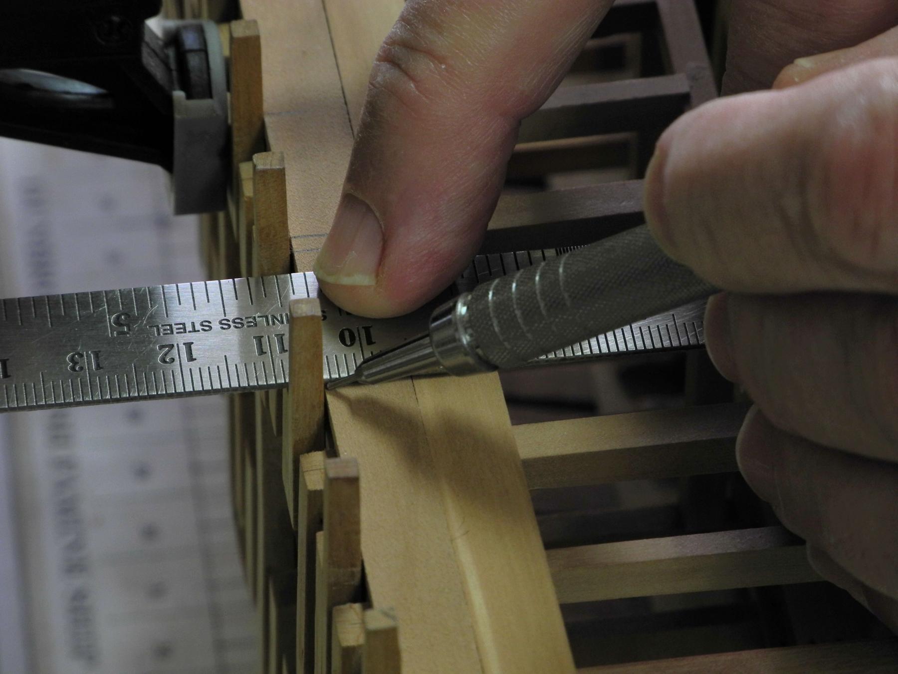
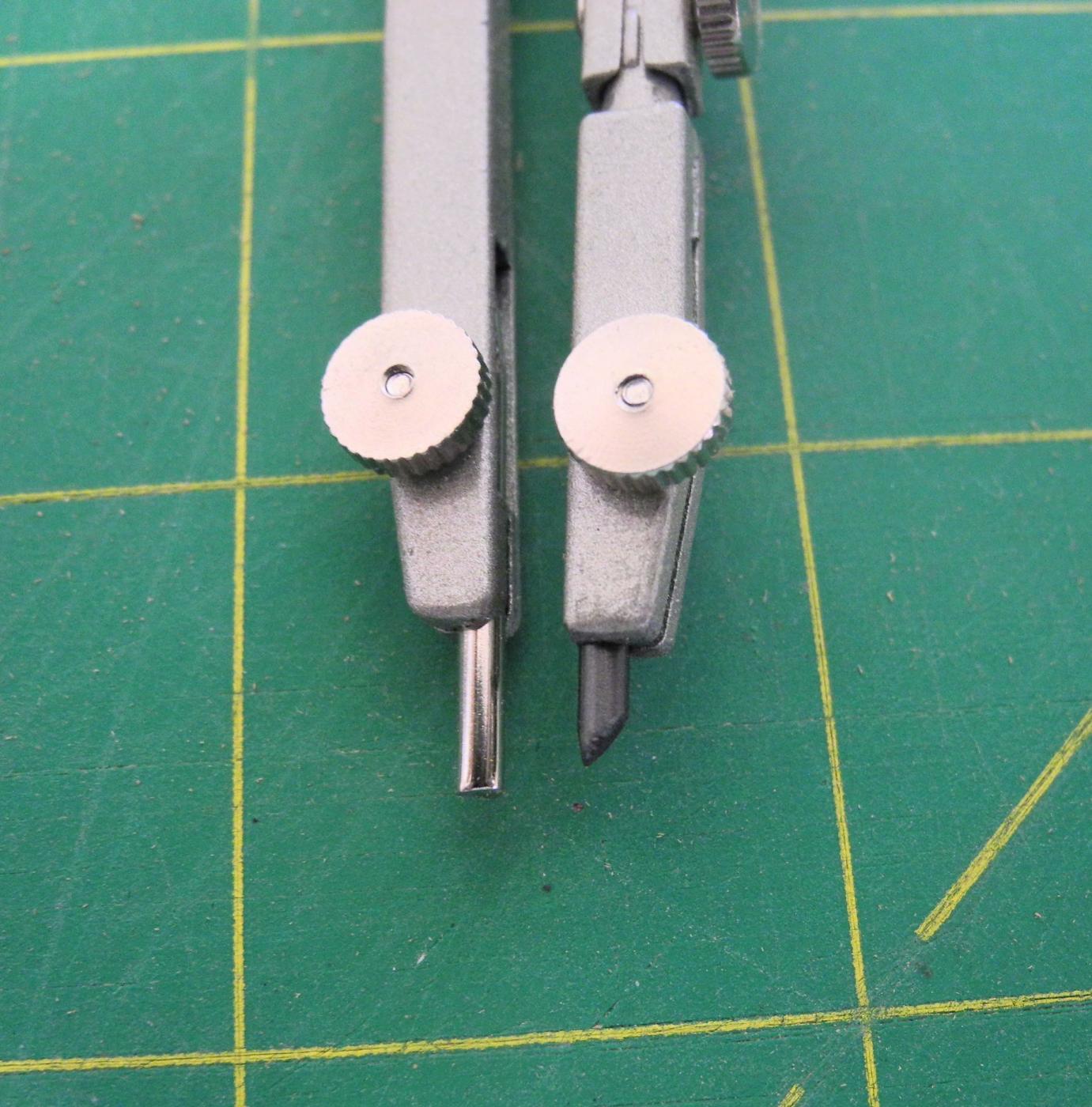
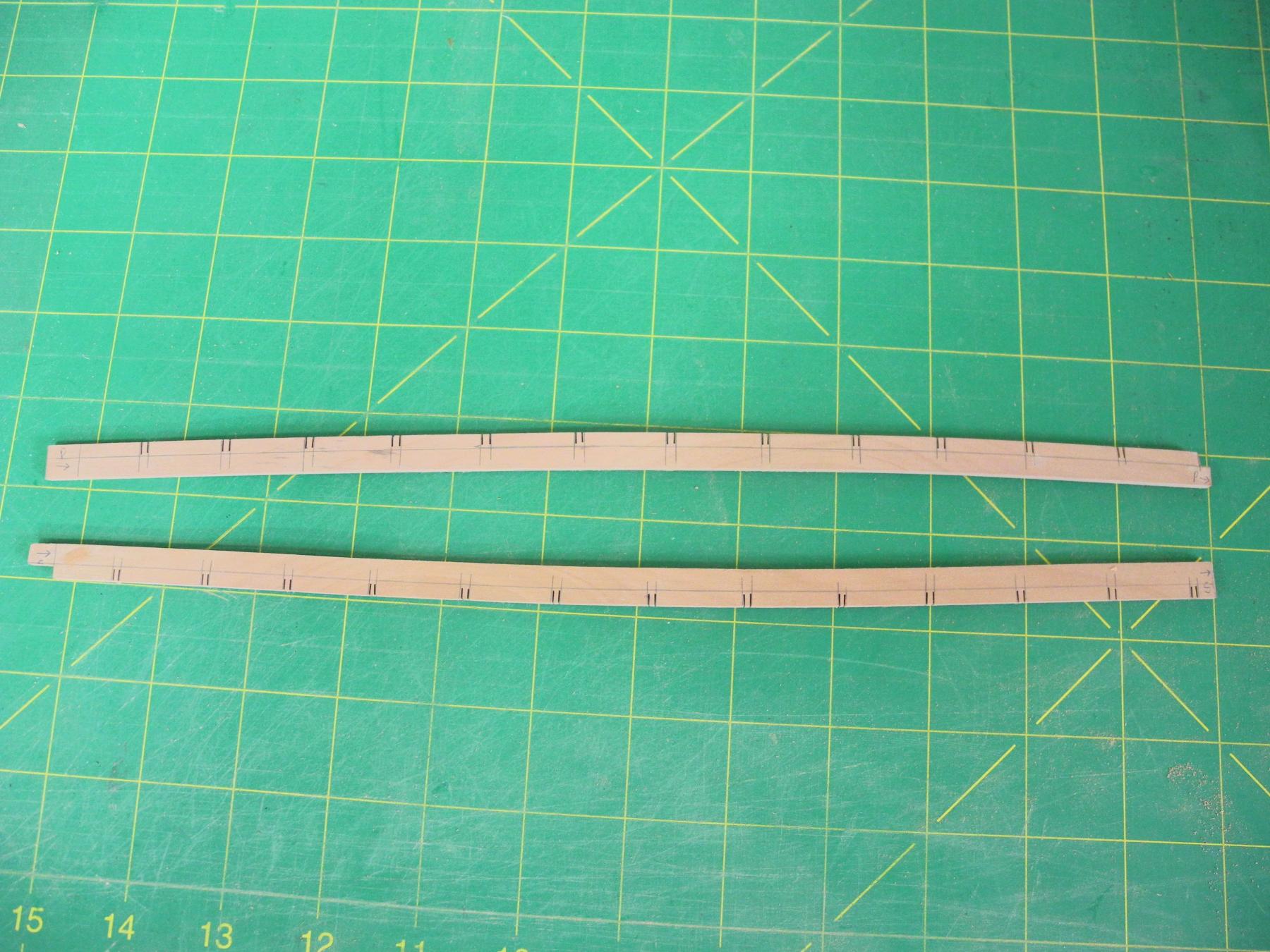
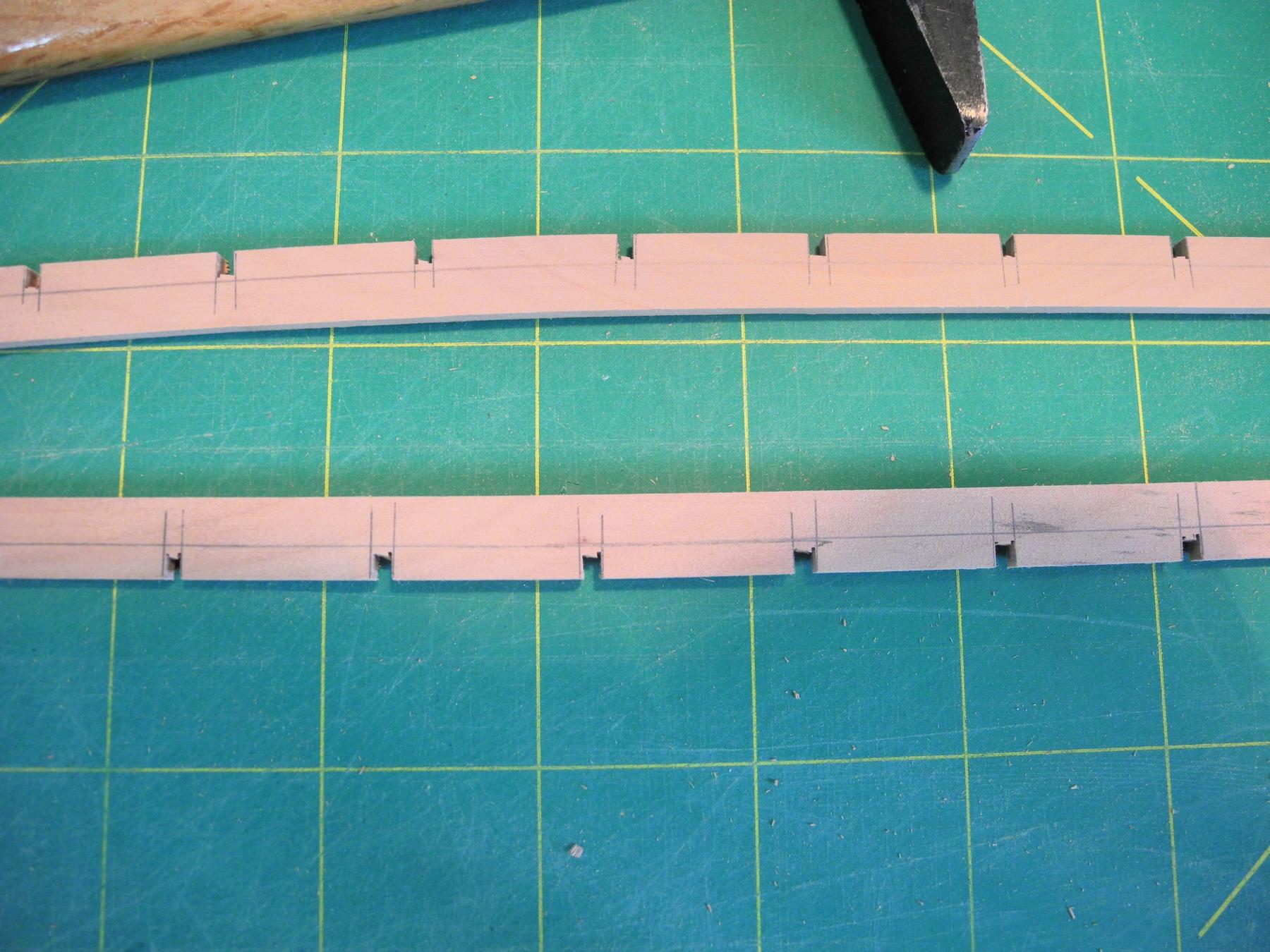
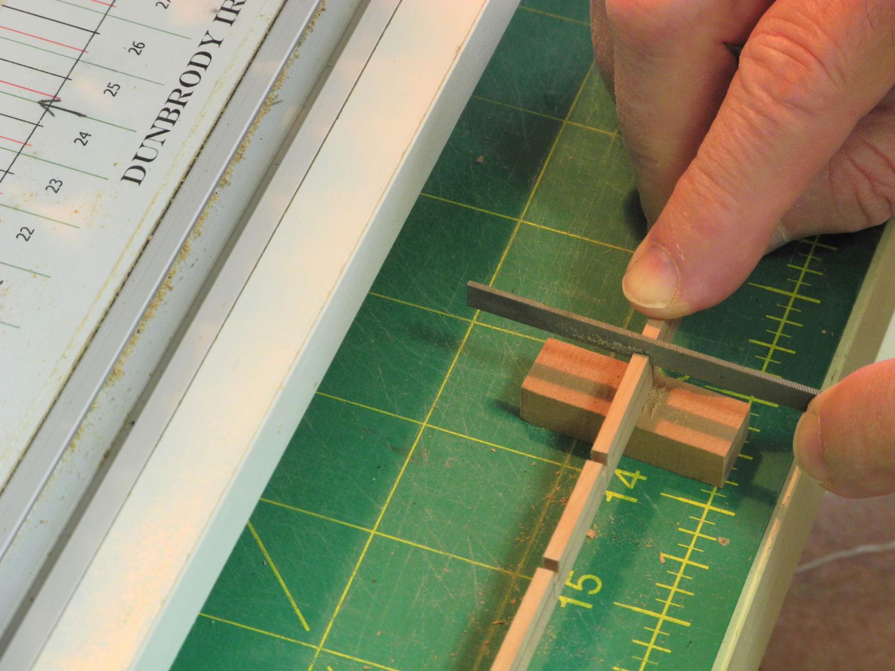
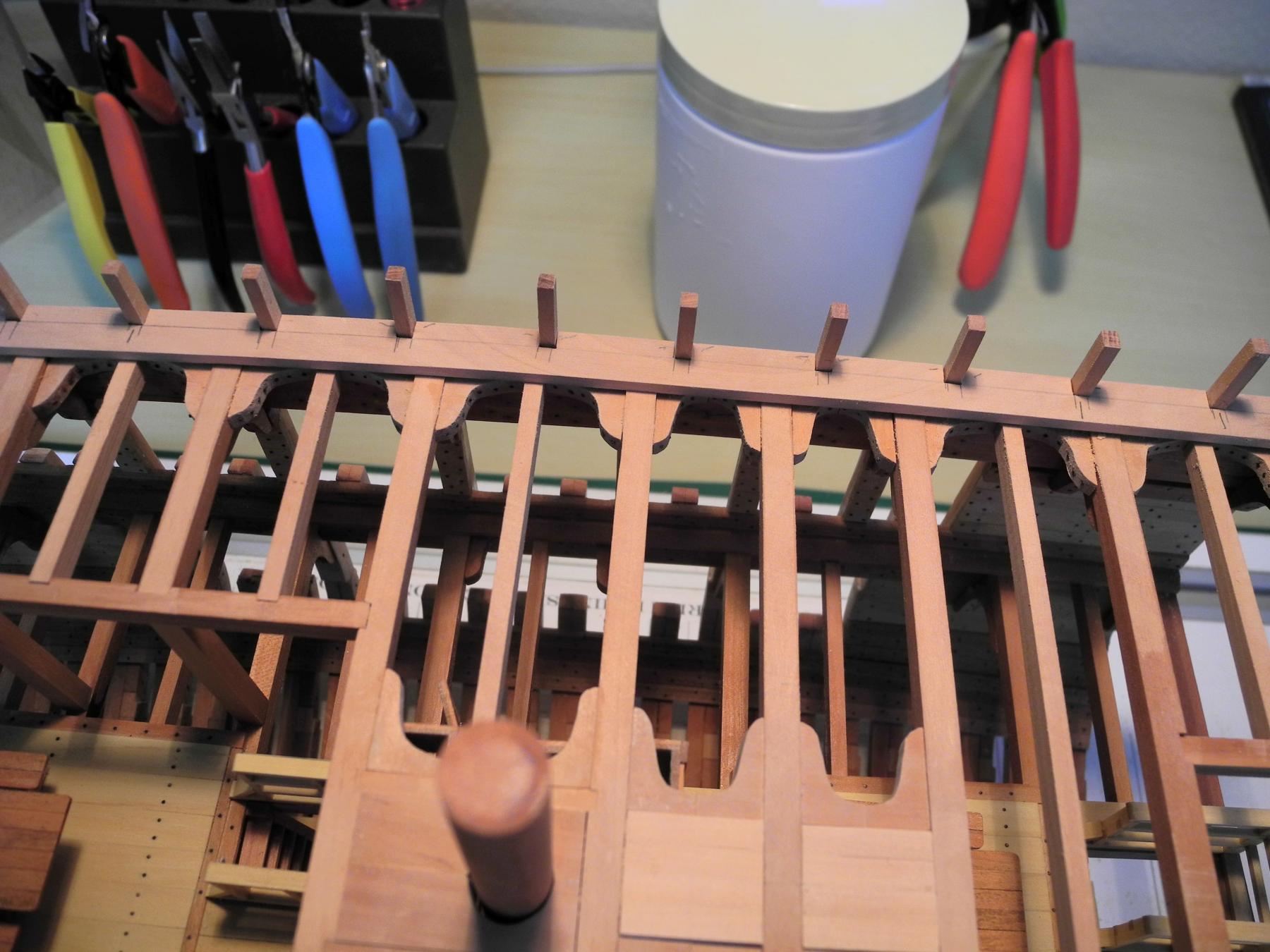
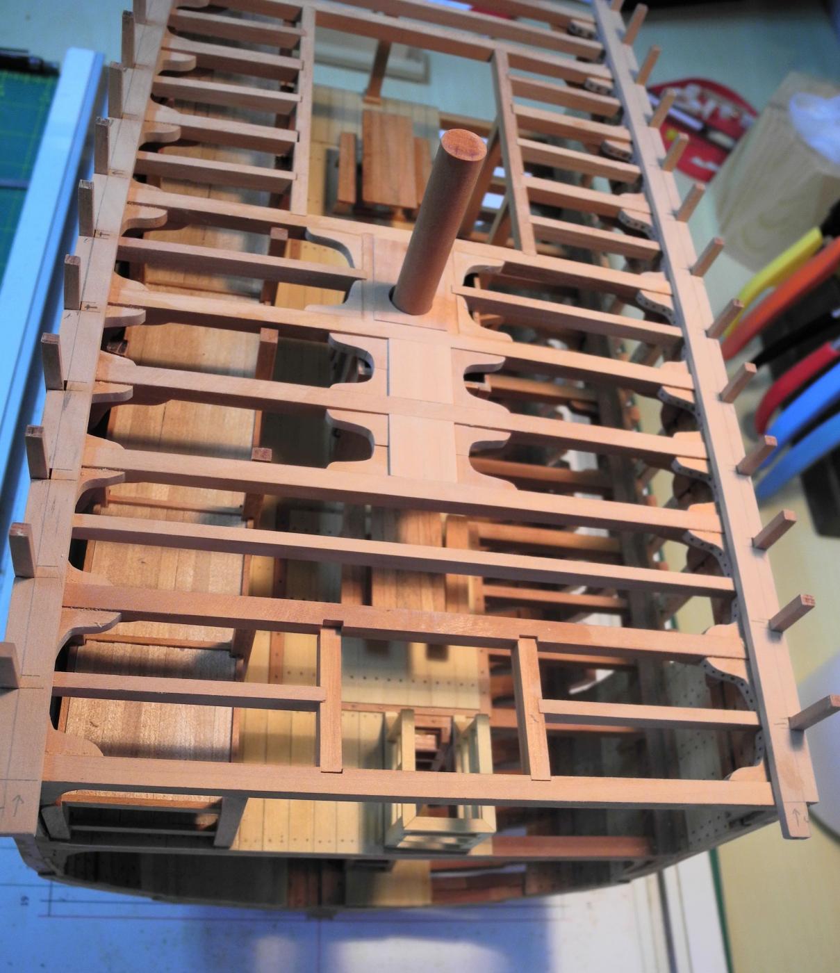
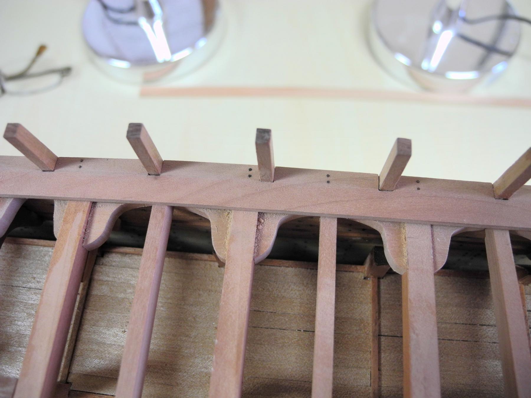
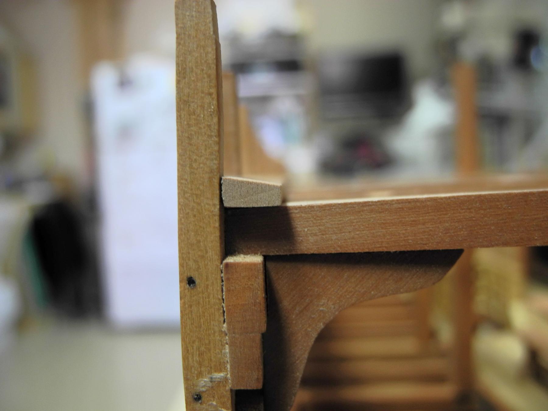
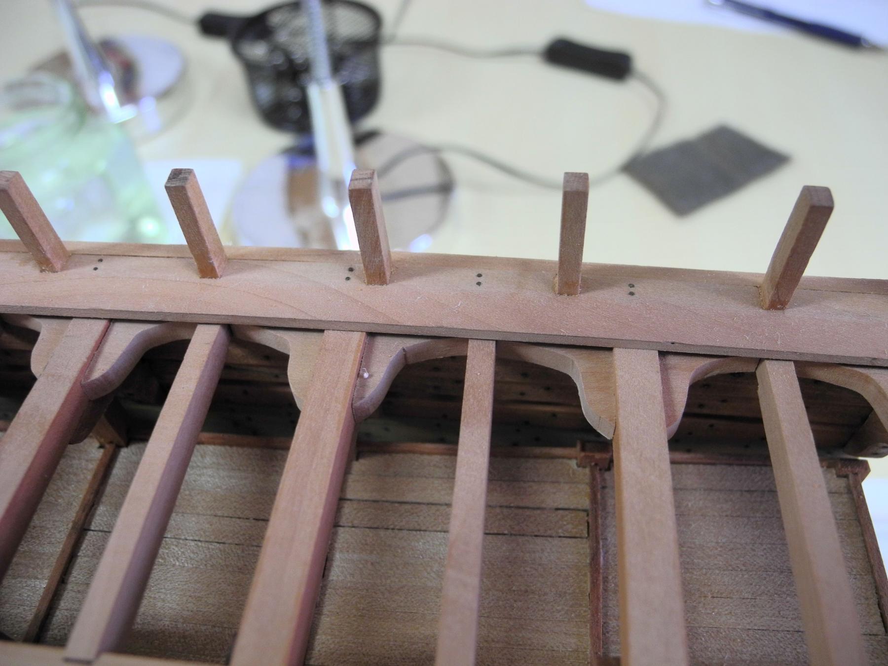
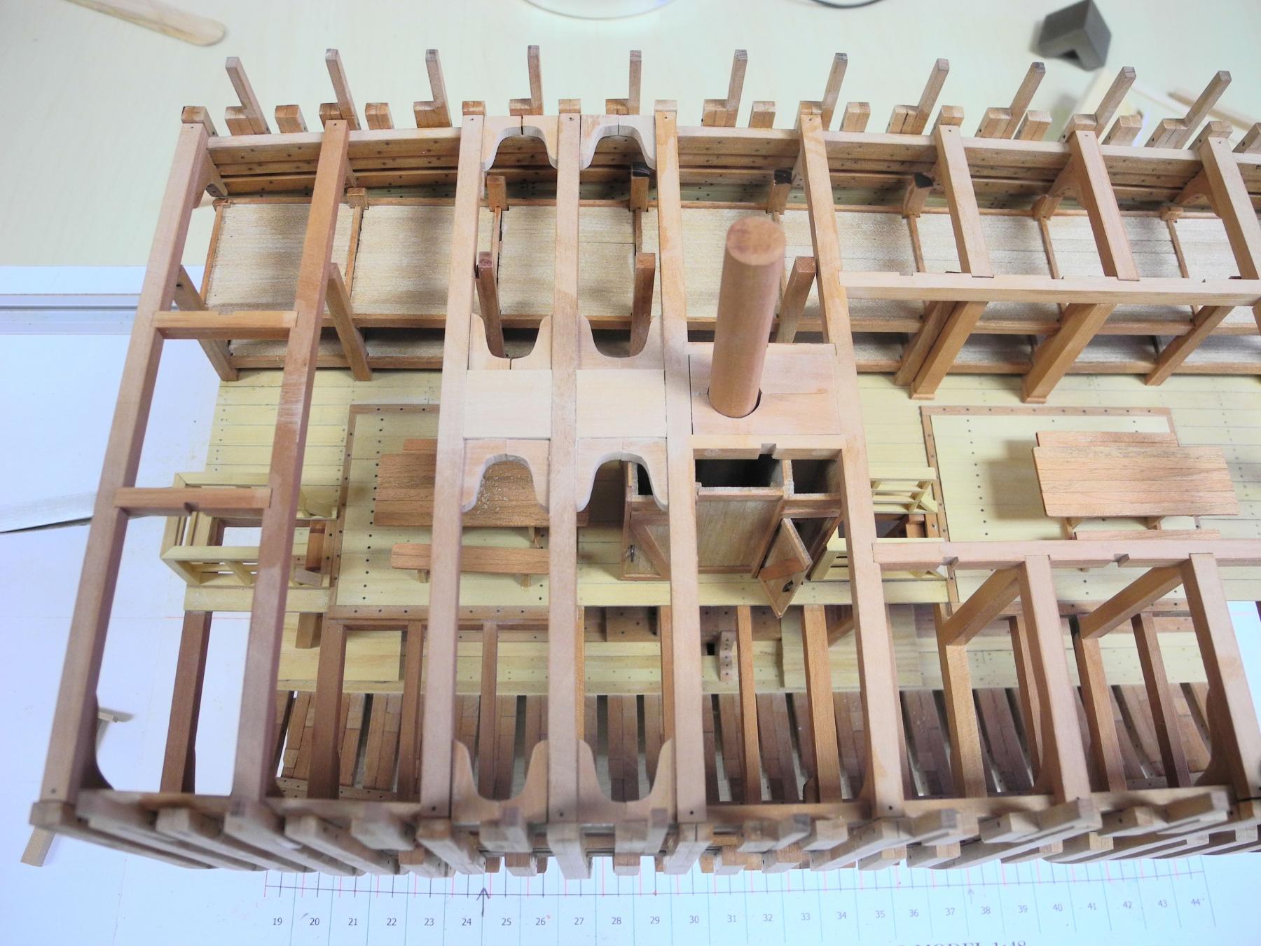
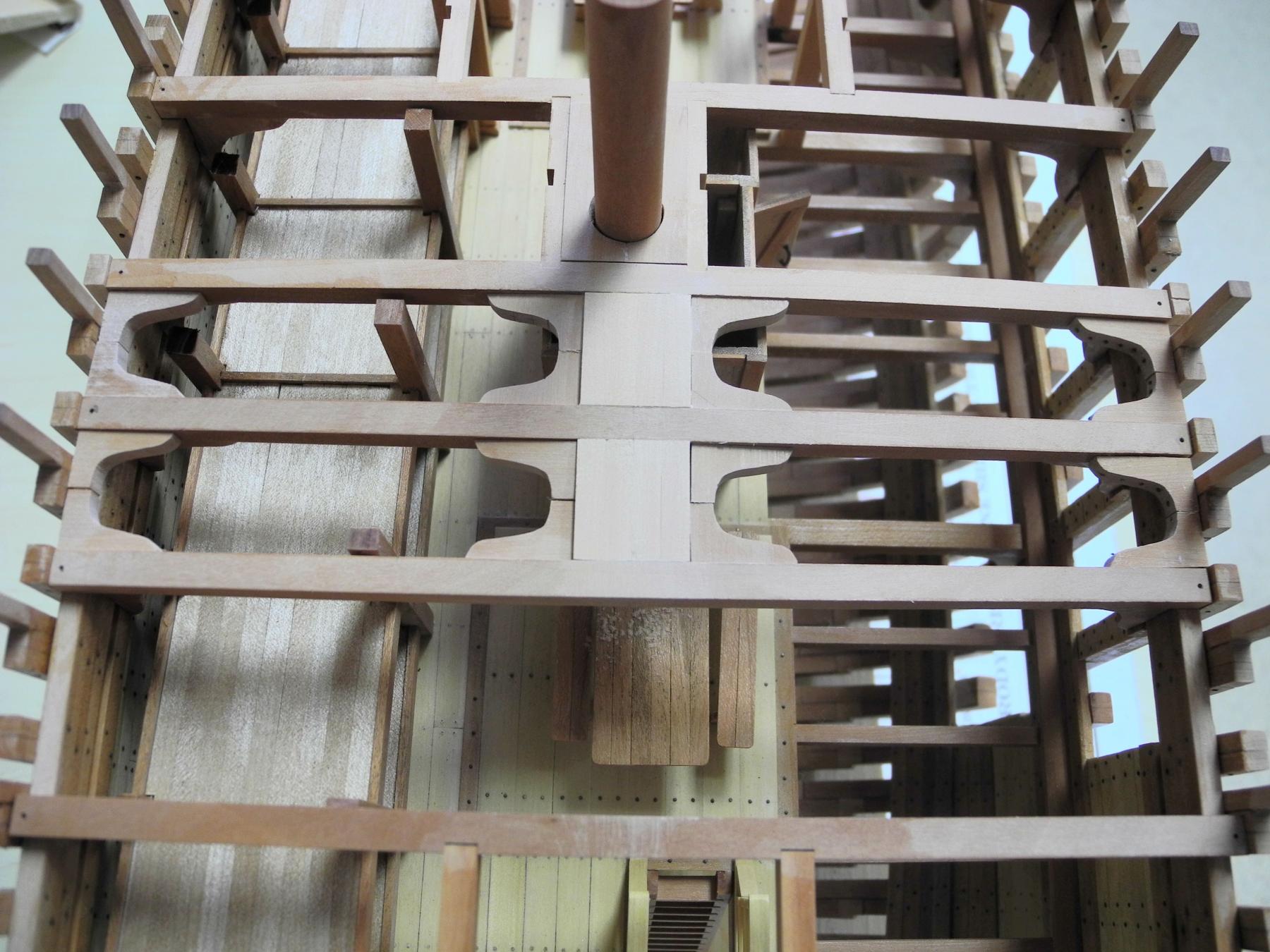
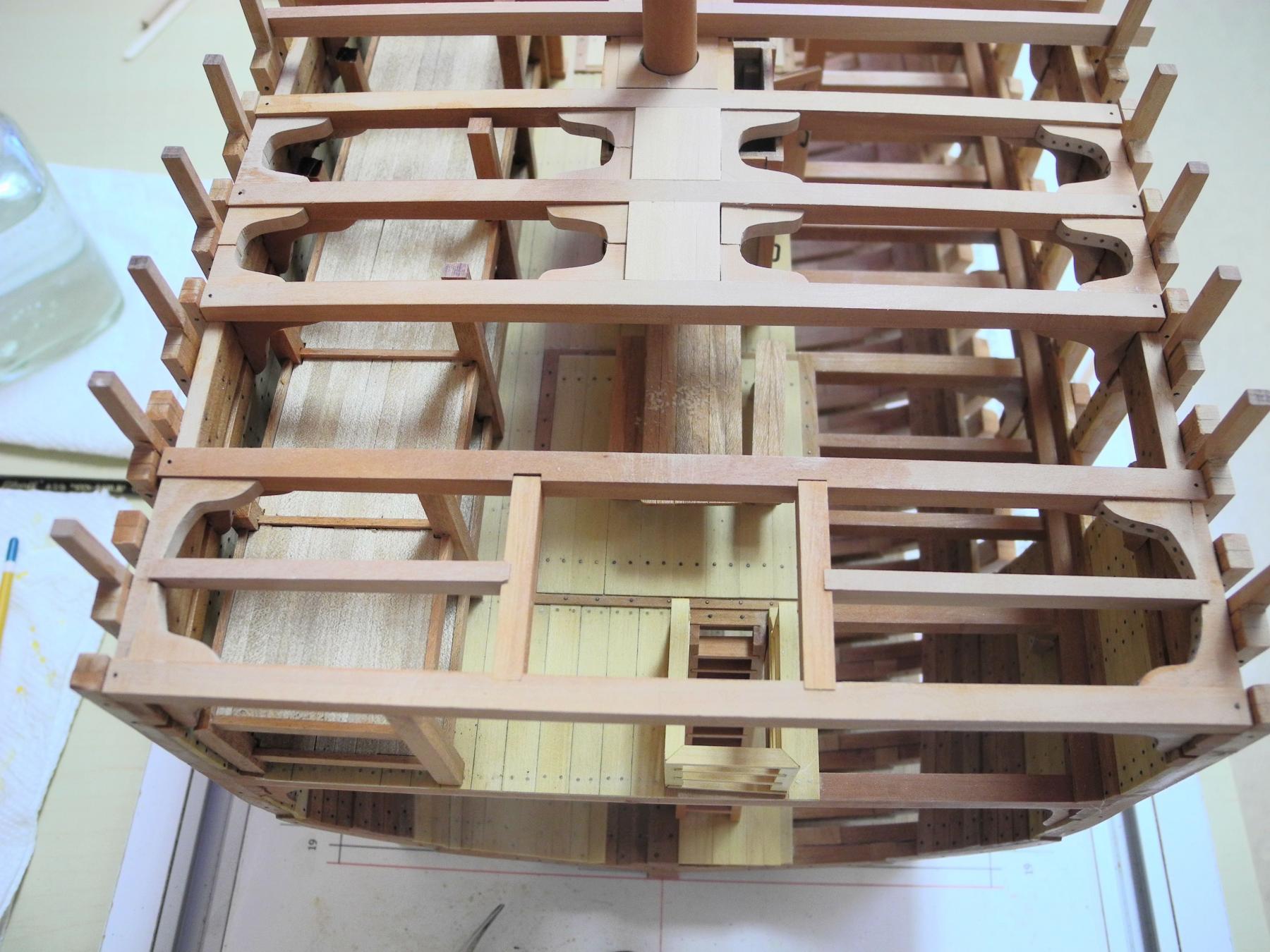
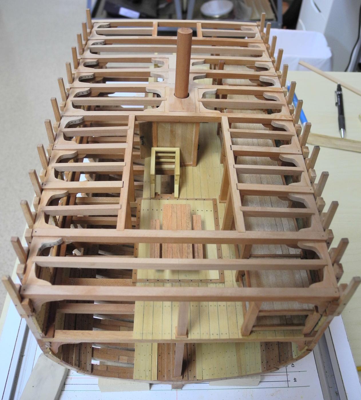
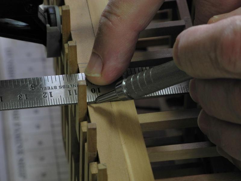
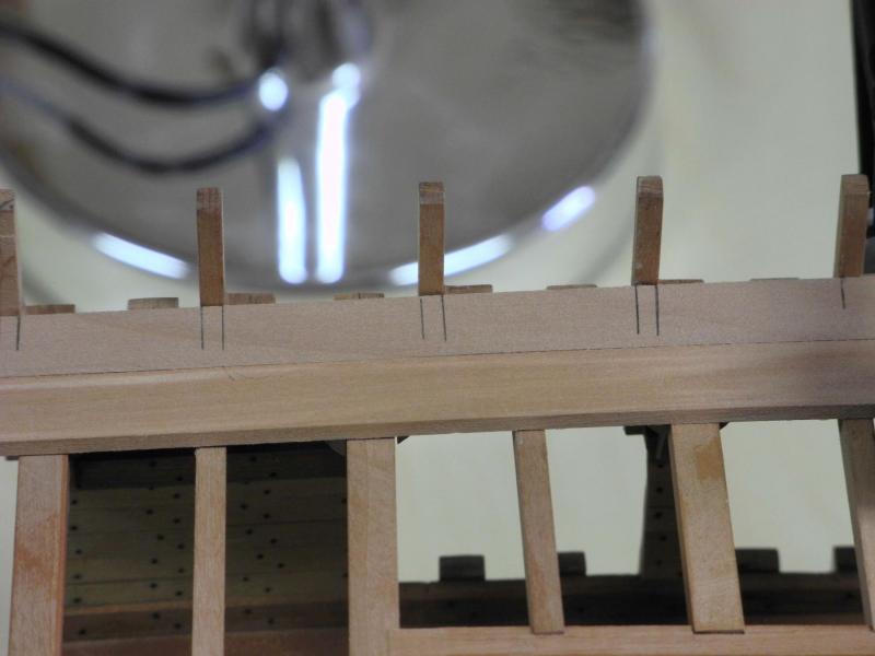
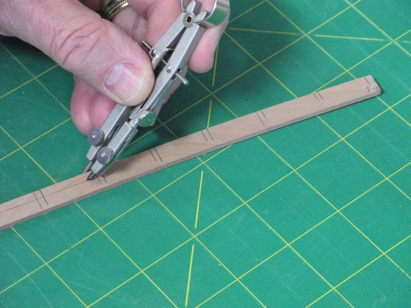
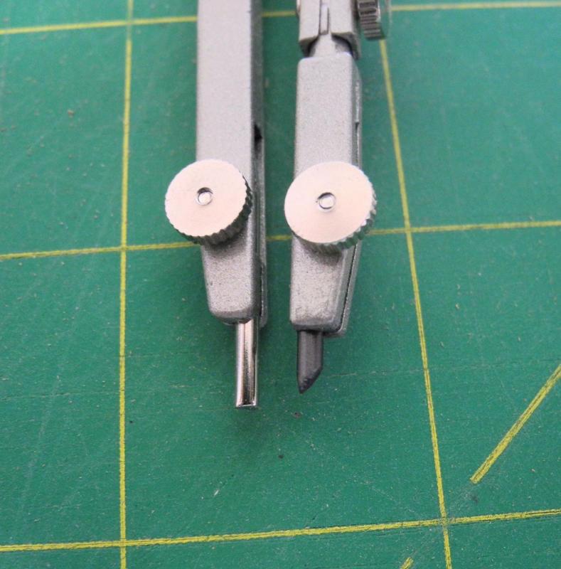
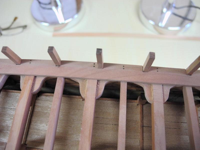
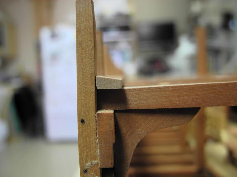
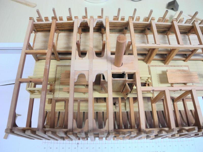
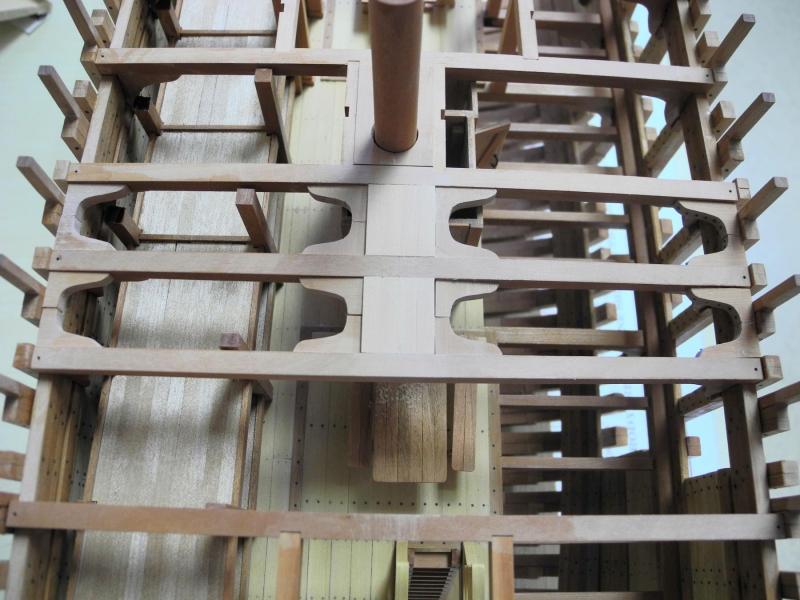
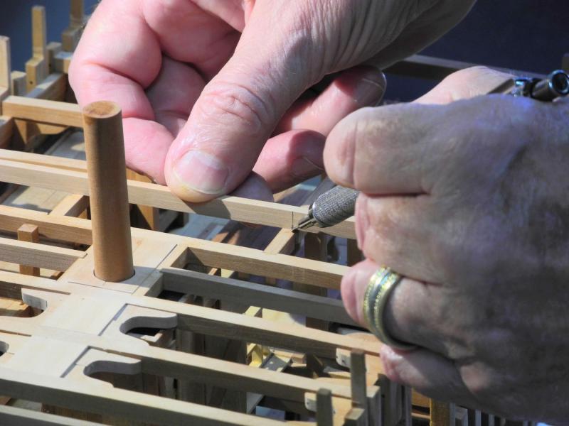
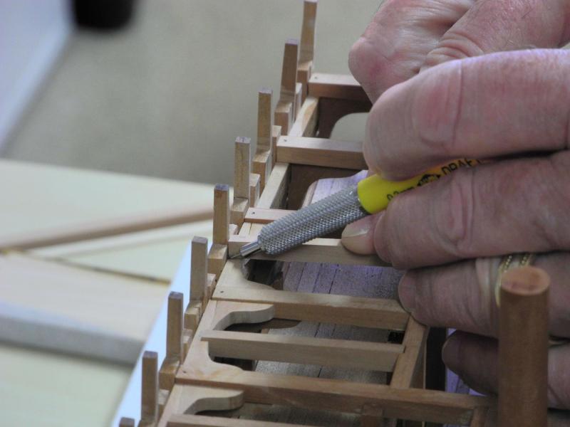
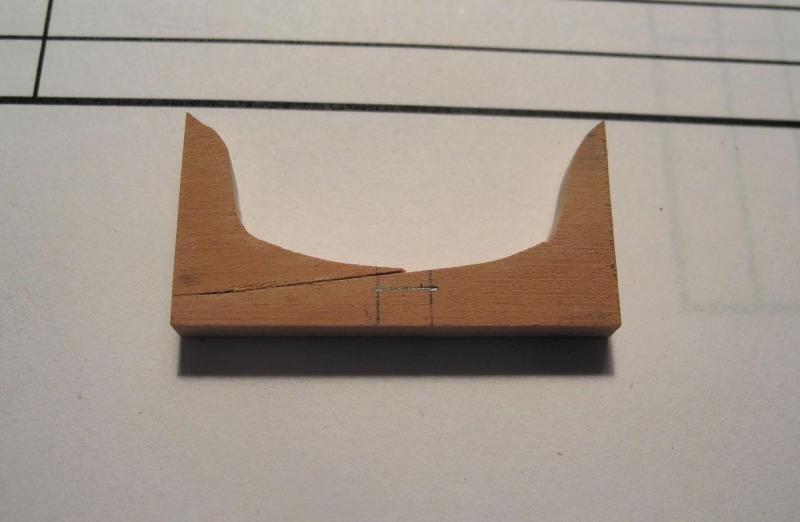
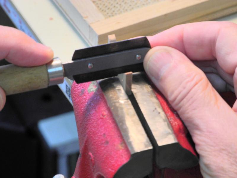
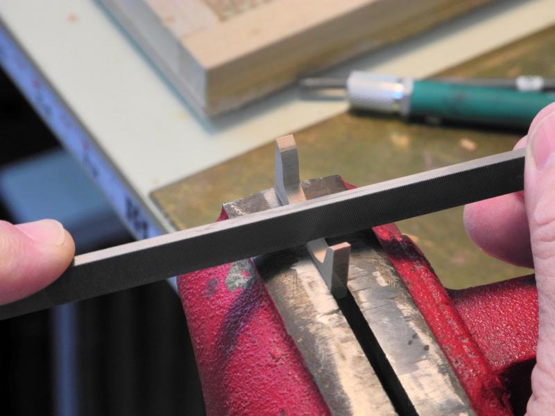
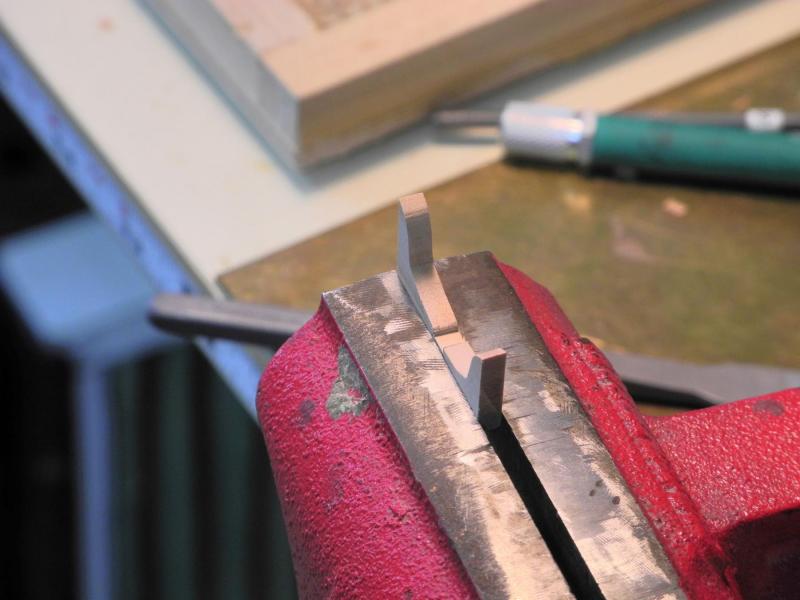
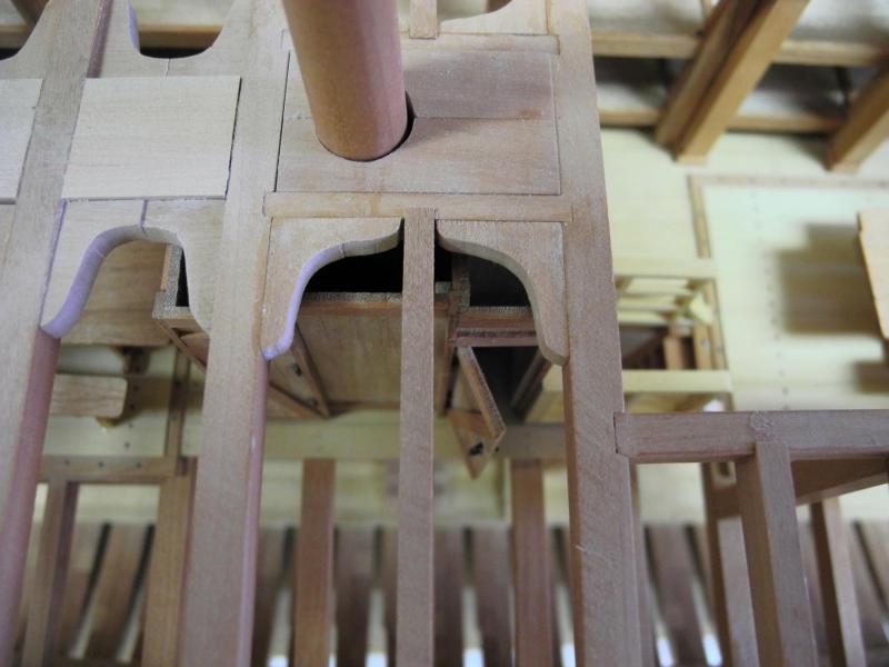
Part 42 – Main Deck Waterways The waterways for the main deck are the next item to be installed. When I made the frames I left the top timbers long, so the first task was to bring the top timbers down to the appropriate height. Masking tape was used to mark the proper height of the top timbers. Some of the top timbers had to be reduced a significant amount, so an Iwasaki fine file was used. This file has a cutting surface that’s similar to a microplane. This file brought the tops done quickly, and even though it has blank edges I let it drift away from the stanchion to avoid cutting into the stanchion in error. It was then a simple matter to finish off the cut using a barrett file. Once all of the top timbers were at the appropriate heights the waterways could be started. As in several other circumstances, the way that Dunbrody is built differs from the traditional methods described in the Crothers book. The normal configuration is to have a waterway with a scupper cut through it and with a planksheer or covering plank fixed above it. The Dunbrody only has a waterway with no planksheer, and instead of scuppers it has openings in the first bulwark plank to remove the water from the deck. This is also shown on the construction plans, so that’s the way the model will be configured. The stock for the waterways was soaked in boiling water and was then clamped in place for drying. A ‘sacrificial’ plank was used to avoid having the clamps cause any denting in the borders of the waterways. After the waterways were dried overnight, the positions of the stanchions were marked on each waterway. The pencil lines are inside the edge of the stanchion as indicated by the straight edge. This was done intentionally so that as the openings were cut there was no risk of making the openings too big. The depth of the stanchions was also marked on the waterways, using a compass set at the appropriate depth. The metal point of the compass was reversed so that the compass would ride consistently against the edge of the waterway. The following photo shows the two waterways after bending and marking. There was a small tendency for the waterways to spring back into a straight line, but the remaining bend can be forced through clamping. The scroll saw was used for the initial cuts, staying inside the pencil lines, and then a small chisel was used to remove the waste between the cuts. These initial cuts left a lot of final shaping to be done. The shaping was done with various files. The small block shown under the waterway was used to prevent the filing from changing the curve of the waterway through downward pressure on the edge of the waterway. The following photos show the waterways after the opening for the stanchions were completed. The waterways have an incline from the stanchions down to the deck planking, so that the edge of the waterway meets the deck planking at the same height as the top of the plank. The depth of the plank was marked on the waterway. This incline was made using a variety of files. The following photo shows the resultant incline in the waterway. The waterways are bolted to the deck beams, so blackened copper wire was used to simulate these bolts. The waterways were then glued in place on Dunbrody. The outer edge of the waterways is an added piece of stock of the same thickness as the waterway. The outer edge of this piece is rounded and is fitted so that it protrudes beyond the waist planking and the bulwark planking, appearing as a molding piece on the ship. The round edge was formed using a stainless cutter that was made to the correct shape and then used as a scraper. This outer edge was then glued in place. The waterways are now finished, and the exterior planking can begin. Thanks everyone for the ‘likes’ and comments.


- 649 replies
-
- 29
-
-
- dunbrody
- famine ship
- (and 2 more)
-
Congrats, Druxey! Already added to my Christmas wish list.
- 641 replies
-
- 3
-
-
- greenwich hospital
- barge
- (and 1 more)
-
Thanks Elijah. It may seem fast, but it's also a lot of time in the shop - my hobby has become a full-time job, with some OT thrown in. (but I'm NOT complaining!)
- 649 replies
-
- 7
-
-
- dunbrody
- famine ship
- (and 2 more)
-
That's correct, Brian. I'm trying to get as much done as possible before October, so I'm eliminating any work that won't show in the final product, as long as it's not structural. And, unfortunately, I also have missed a couple of things by mistake - rushing isn't a good thing.
- 649 replies
-
- 5
-
-
- dunbrody
- famine ship
- (and 2 more)
-
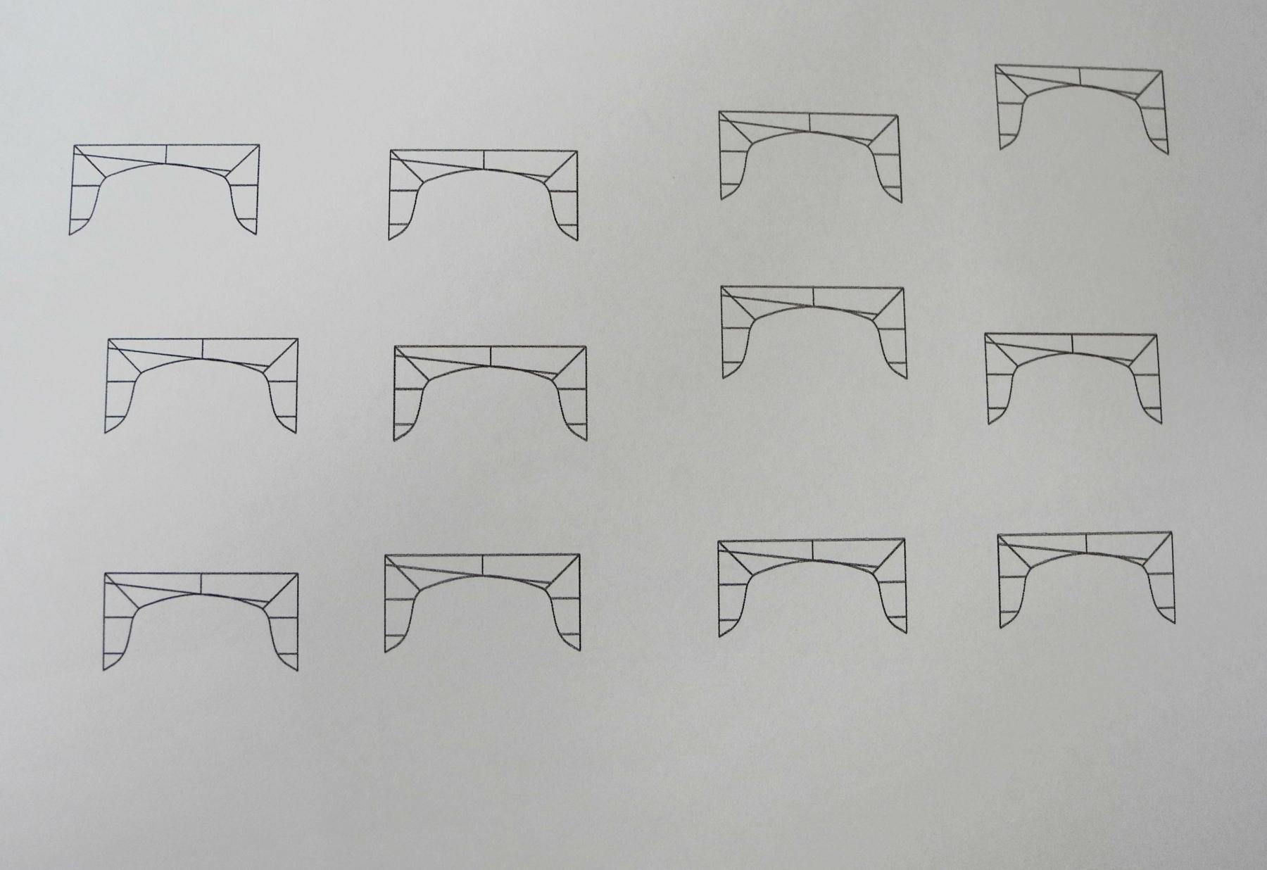
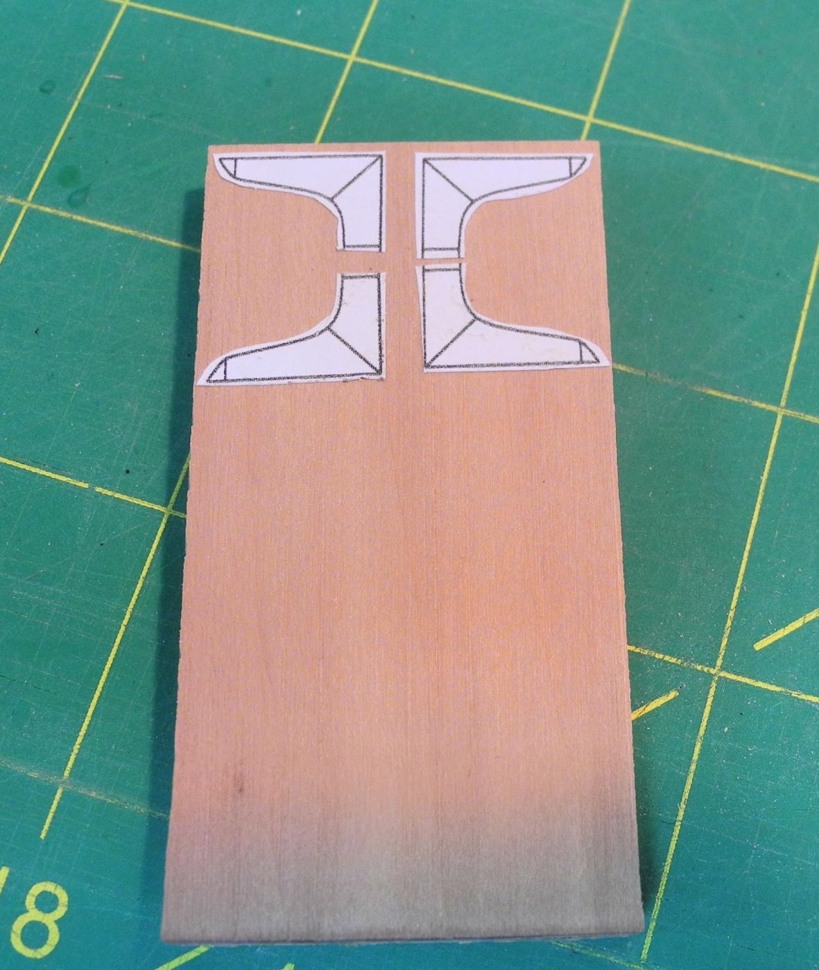
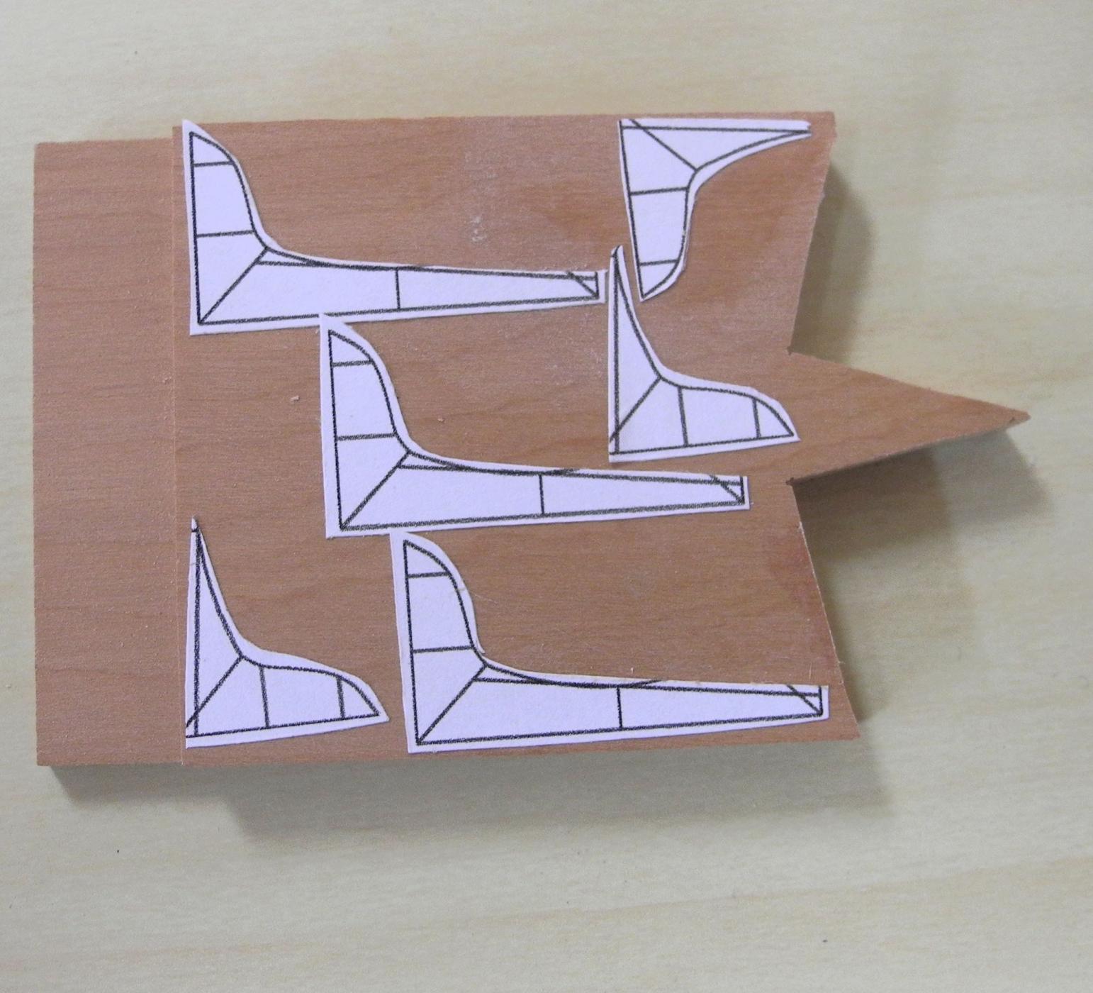
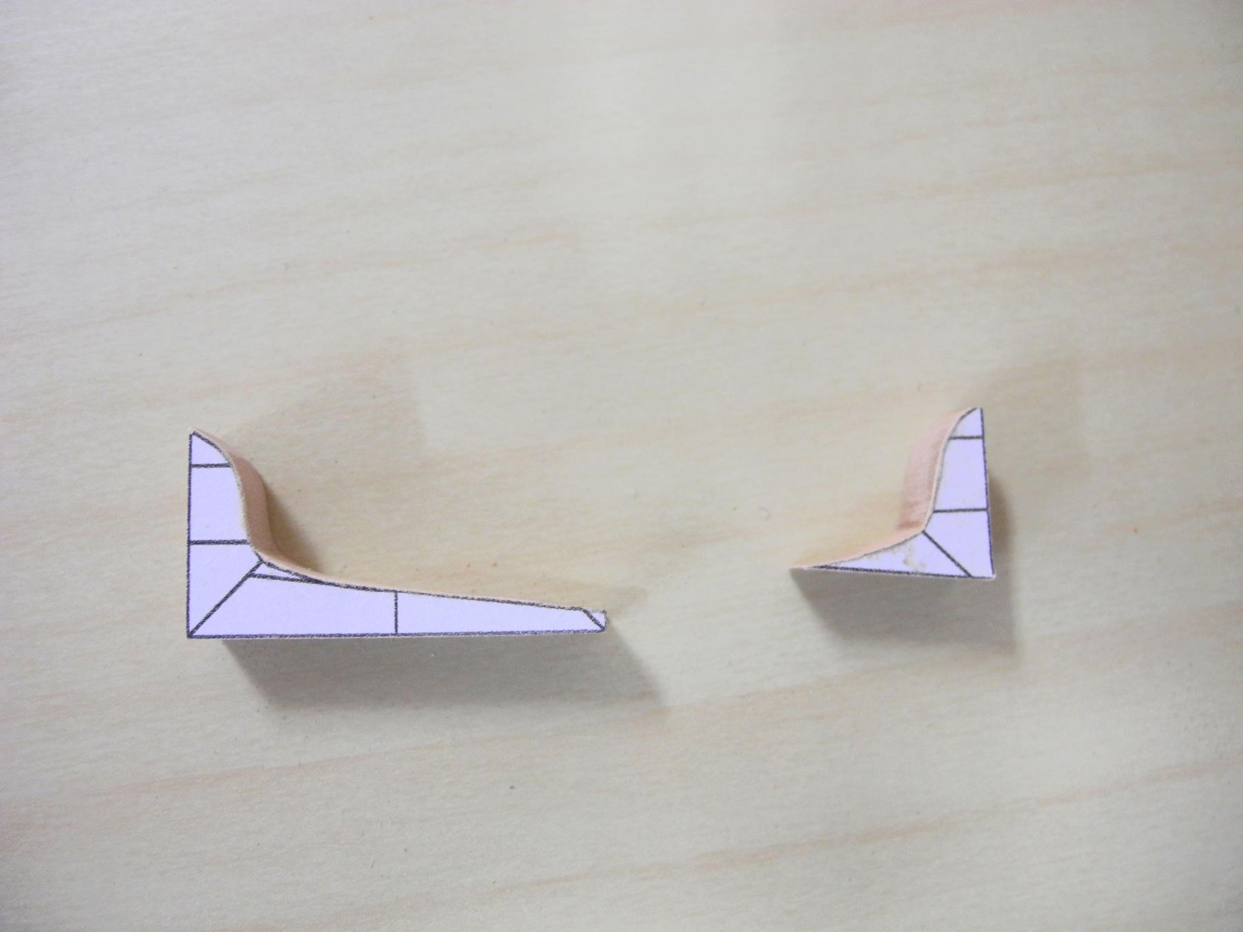
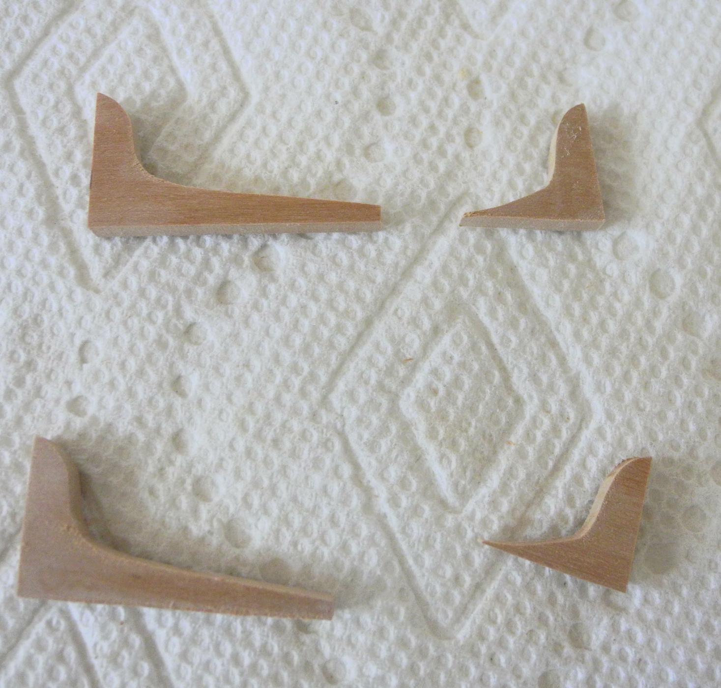
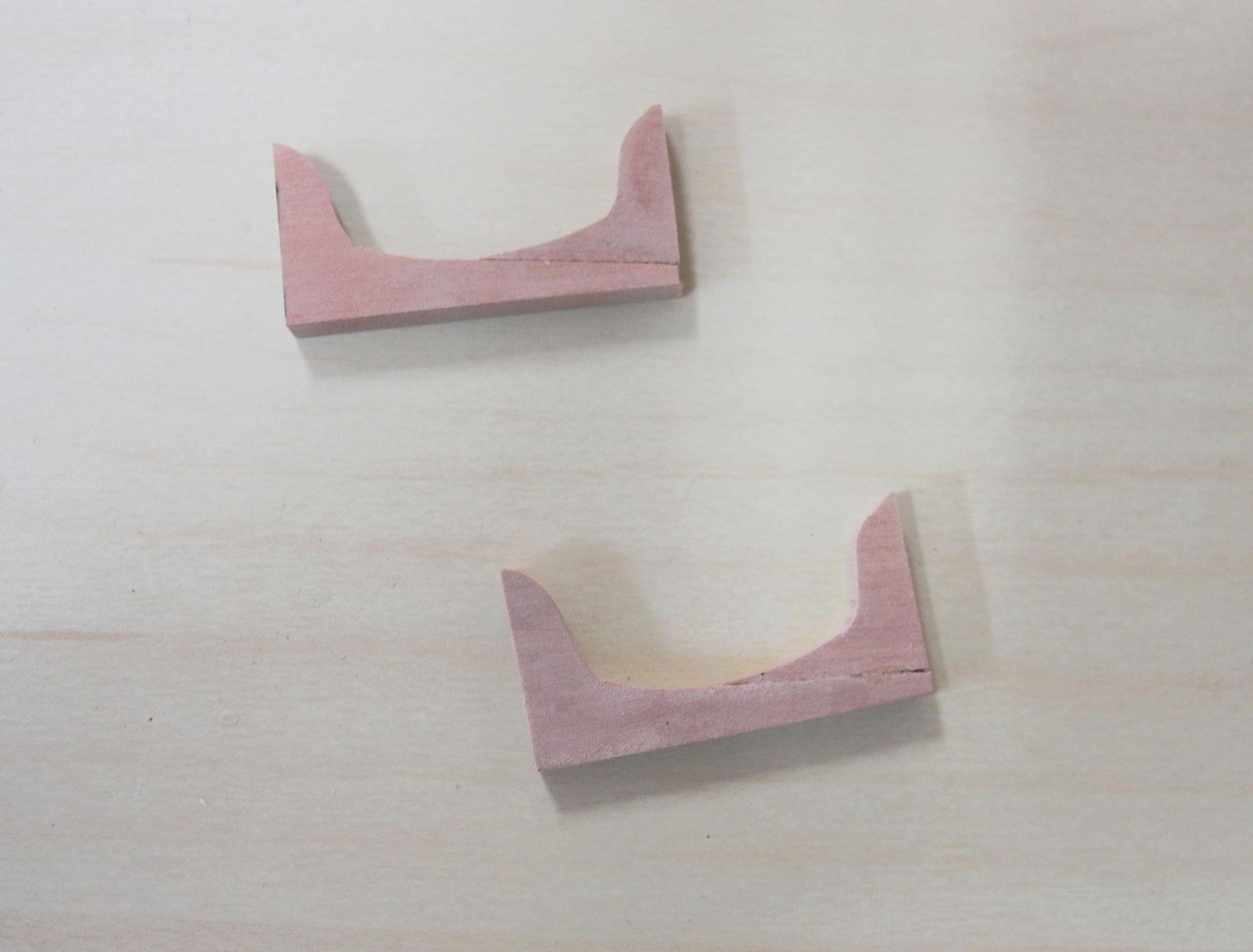
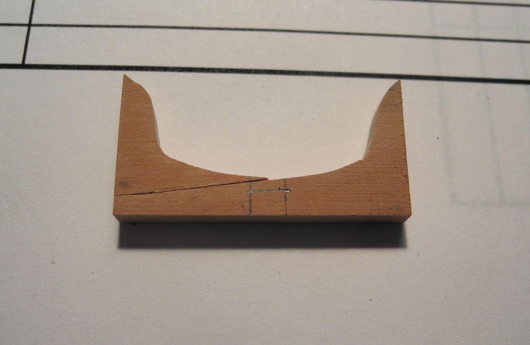
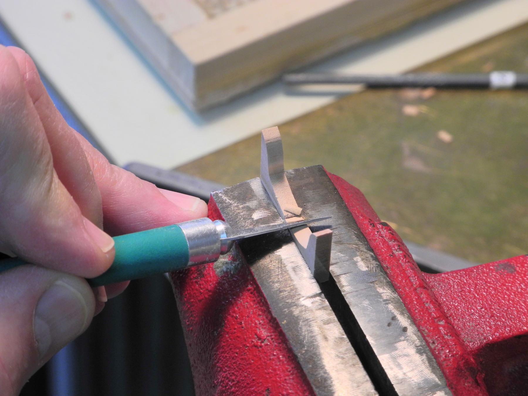
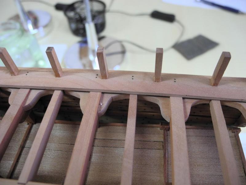
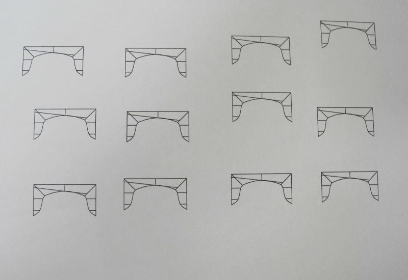
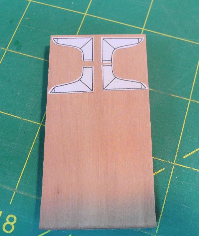
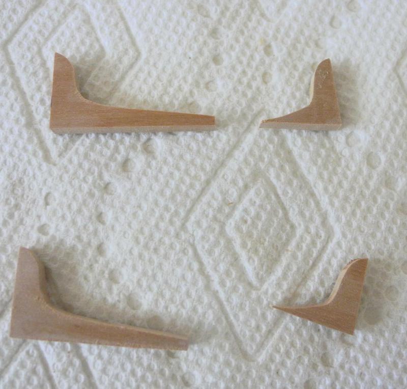
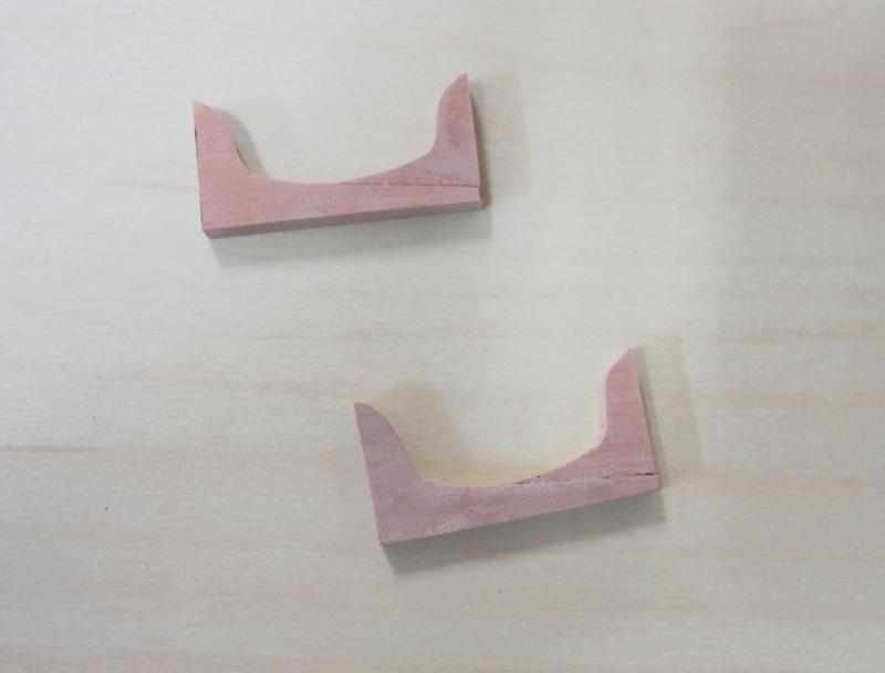
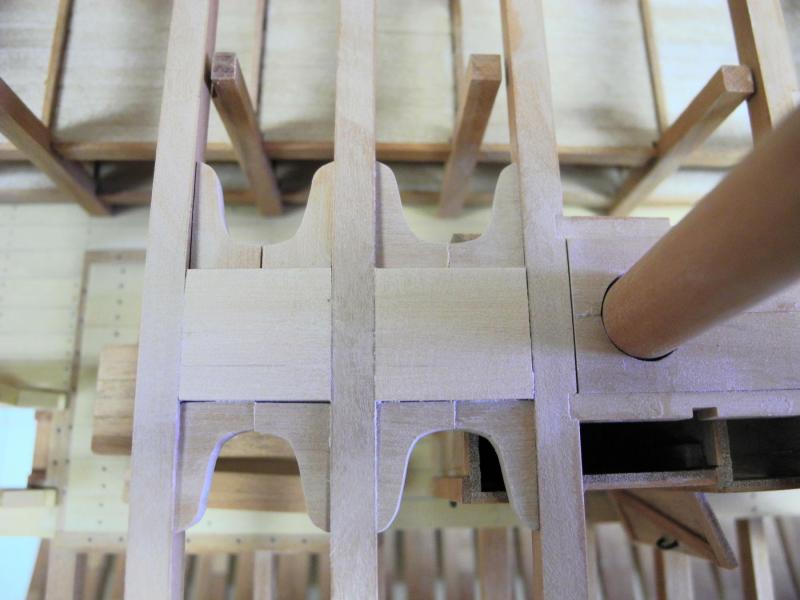
Part 41 – Main Deck Lodging Knees There are several variations of lodging knees described in the Crothers book that I’ve been using as a reference. Dunbrody uses 3 of the four types, as explained below. Work started with drafting the various knees in CAD. Since the drawings would be cut out and pasted on wood stock for cutting out the knees, sufficient copies were printed to allow construction of all the required knees. The following photo is the drawing of the majority of the knees – knees with a long scarf in each berth. The construction plans show a capstan among the various details on the main deck, but they don’t show any underlying support for the capstan. The capstan is over part of the aft hatch, so I’m not sure what the arrangement was. I didn’t look far enough ahead in the building, so I didn’t include any capstan support under the main deck – my error. To try to compensate I added some heavy beams behind the mast partners on the main deck. The area around the capstan had some simple butted lodging knees on the plan, so I added the new timbers inside the knees. For cutting the knees, 2 pieces of stock were glued together using Ambroid glue – this allowed me to cut out a pair of knees at a time. The following photo shows the capstan knees. The knees with the long scarf were used to support he main beams and the secondary or partial beams that were between them. The process for making these knees started with pasting the drawings to the stock using an Elmer’s School Glue stick. The knees were cut out on the scroll saw and shaped using the disk sander and a round sanding stick for the concave part. The knees were then placed in a small bath of acetone in a covered container for a couple of minutes for the Ambroid glue to dissolve – this resulted in the parts for a pair of the scarfed knees. The pieces were glued together to form the scarfed knees. These knees would be positioned between two main beams, with a secondary beam cut into the knee. The knees were first fitted between the main beams, using a disk sander to reduce the width of the knee until it fit snugly in the berth. The secondary and partial beams were manufactured to their full length so that the correct camber was on the beam. For cutting the beam to its final length, the beam was first centered on the deck and the length at its innermost location was marked. Then, with that part of the beam in its permanent position, the other end of the beam was used to mark the beam’s location on the knees. The following photo shows the knees marked for the secondary beam. The cut will be made so that 5 inches of the knee remains. Stop cuts were made at the two lines using a small razor saw. The wood between the cuts was pared out. And the cut was finished with a file. The remaining type of knee used in Dunbrody is the most simple type of knee with no butts or scarfs – used at the mast partners. The lodging knees for Dunbrody are now completed. Next item will be making and installing the waterways. Thanks everyone!


- 649 replies
-
- 22
-
-
- dunbrody
- famine ship
- (and 2 more)
-
Looks great Patrick. I like the floating effect. It looks to me like it's finished - but I'm interested to see what you still feel needs to be done.
-
Hi Mike, and thanks! I'm glad you find this interesting - my main purpose (besides modeling at a level of complexity that is new to me) is to show the conditions in which the emigrants escaping the famine had to travel. I had the same question about the frame chocks - they didn't seem to be necessary. EdT made the point that perhaps they were used to build the single frames before the frames were joined as a frameset. If you're interested, this is one of the discussion topics in my prior topic of Planning for a Sectional Model of the Dunbrody - the link is below my signature. And welcome to my log!
- 649 replies
-
- 6
-
-
- dunbrody
- famine ship
- (and 2 more)