Mahuna
-
Posts
1,504 -
Joined
-
Last visited
Content Type
Profiles
Forums
Gallery
Events
Everything posted by Mahuna
-
 Hi Glenn - the windows are amazing. I always look forward to catching up on your Saturday post at the end of a day in my shop. By the way, is there any possibility of seeing Heroine at the NRG Conference in San Diego? That would be fantastic.
 -
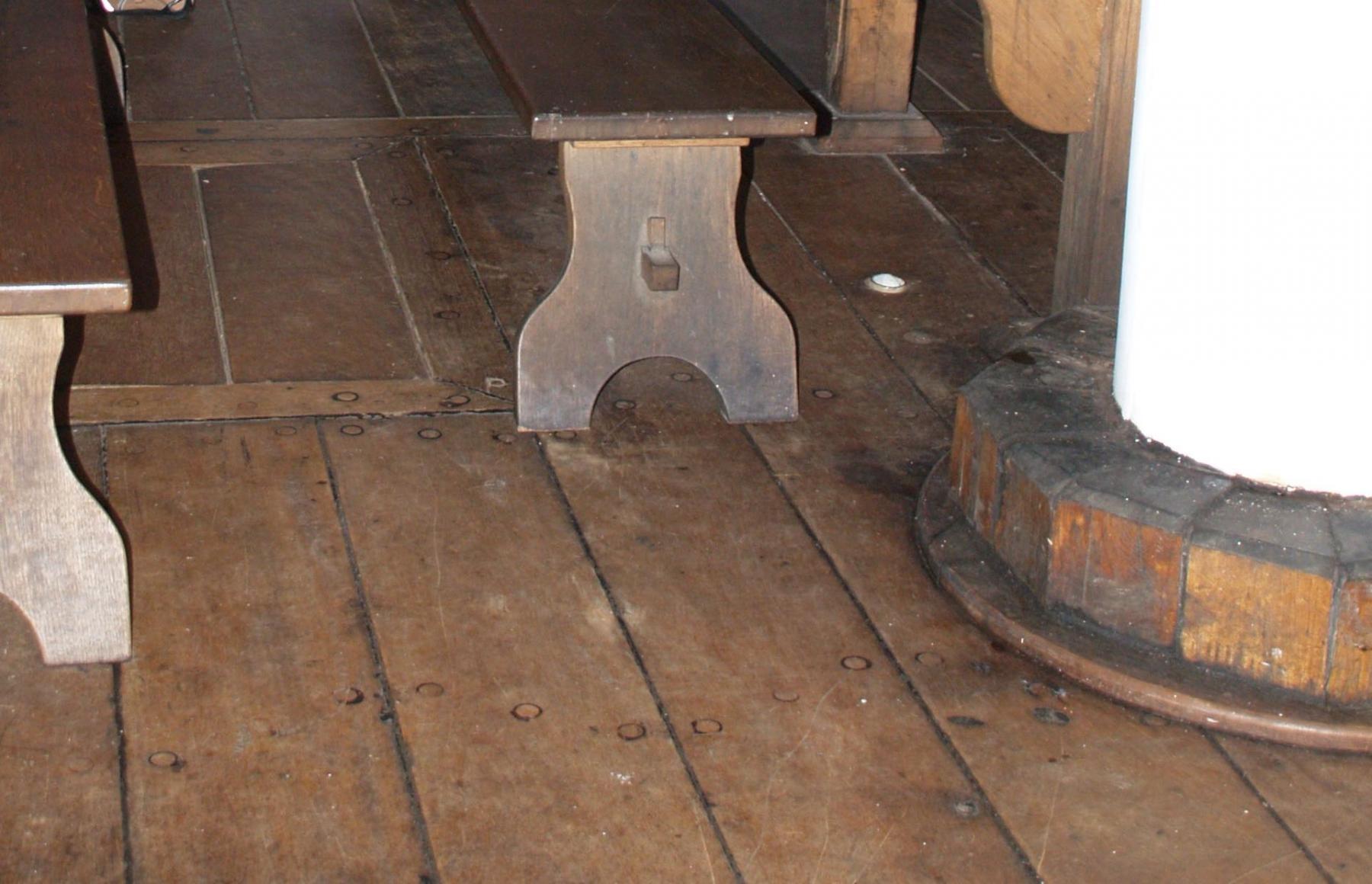
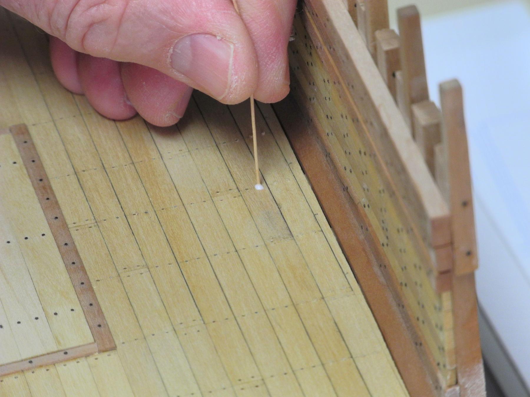
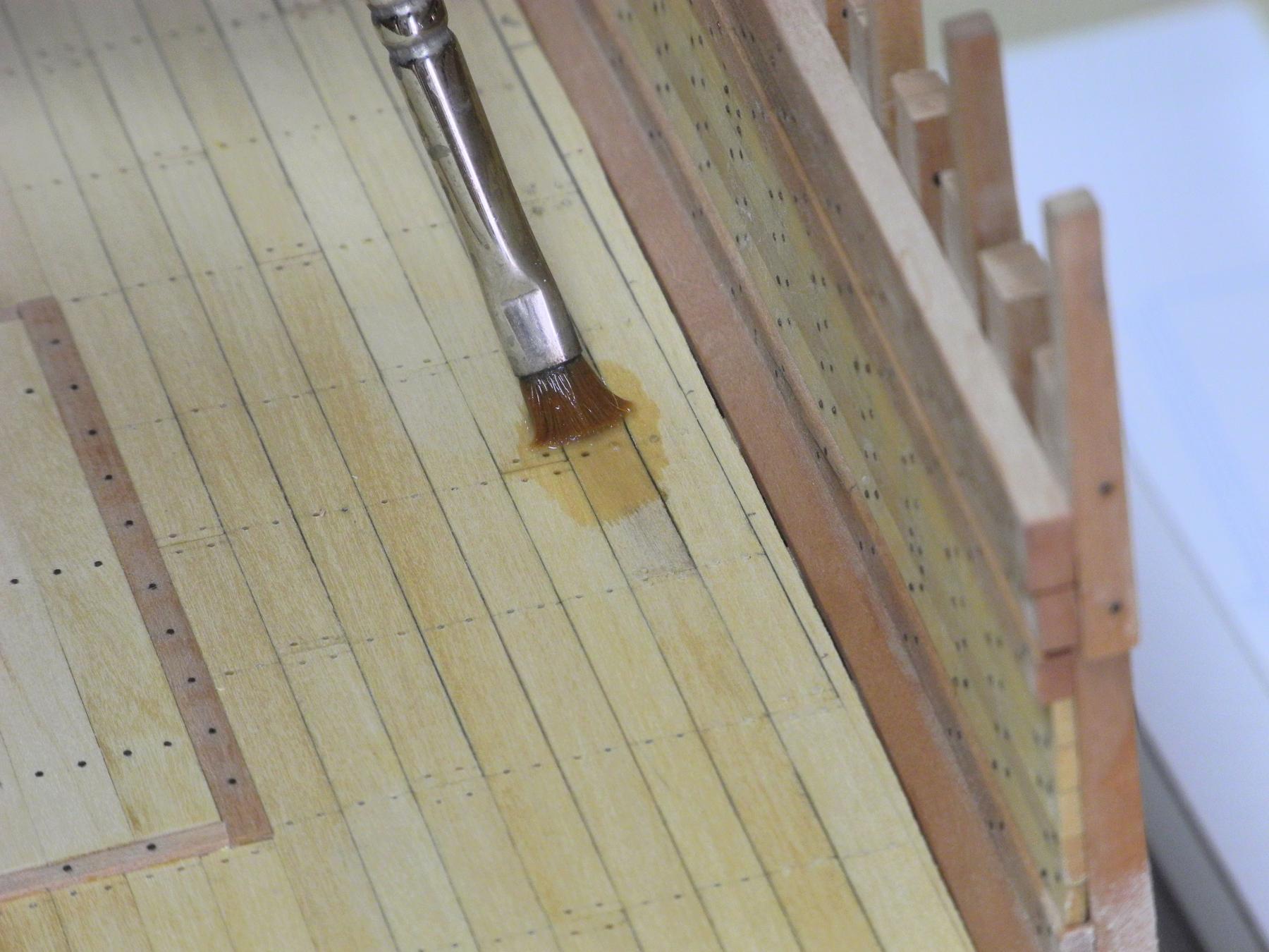
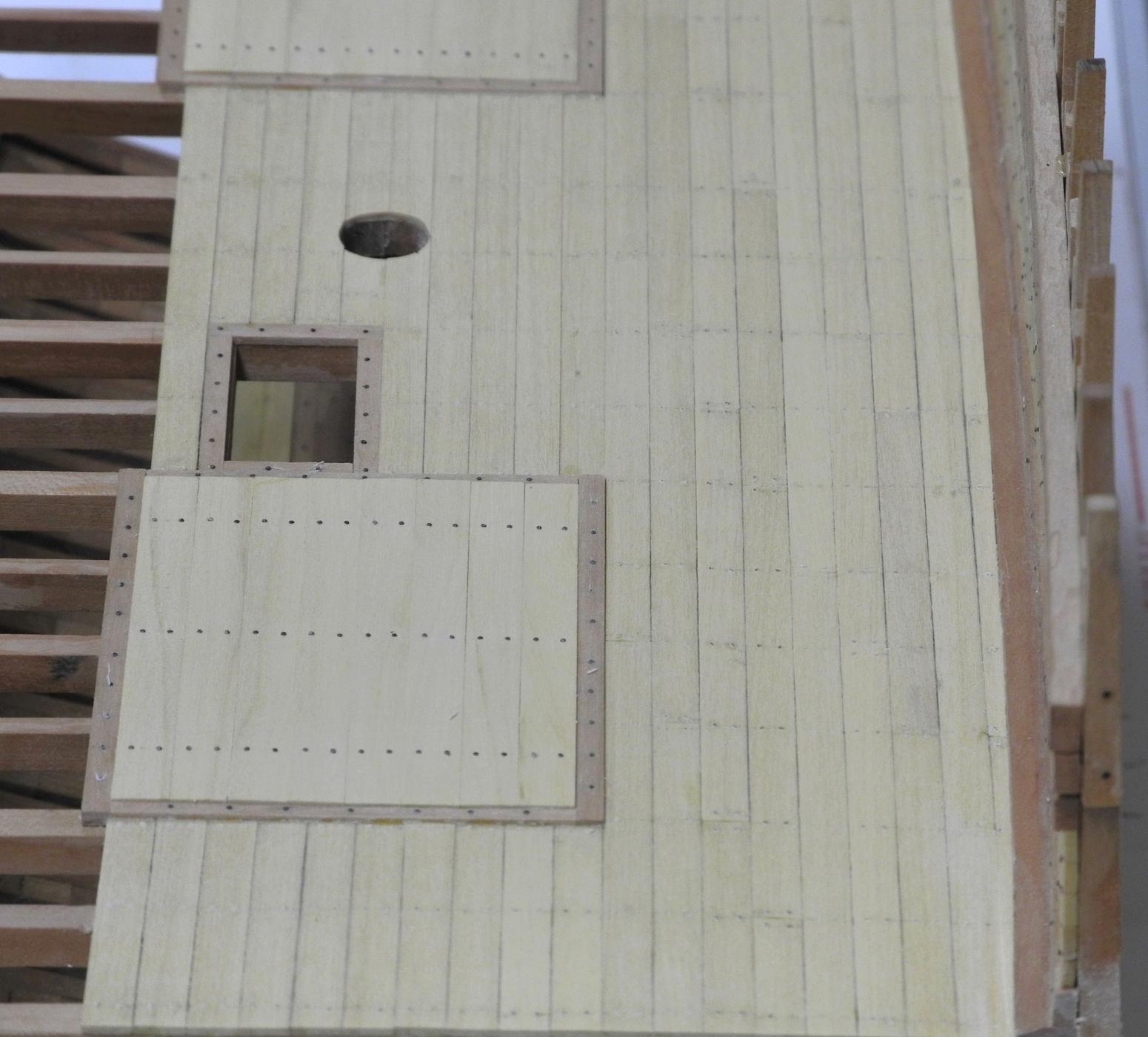
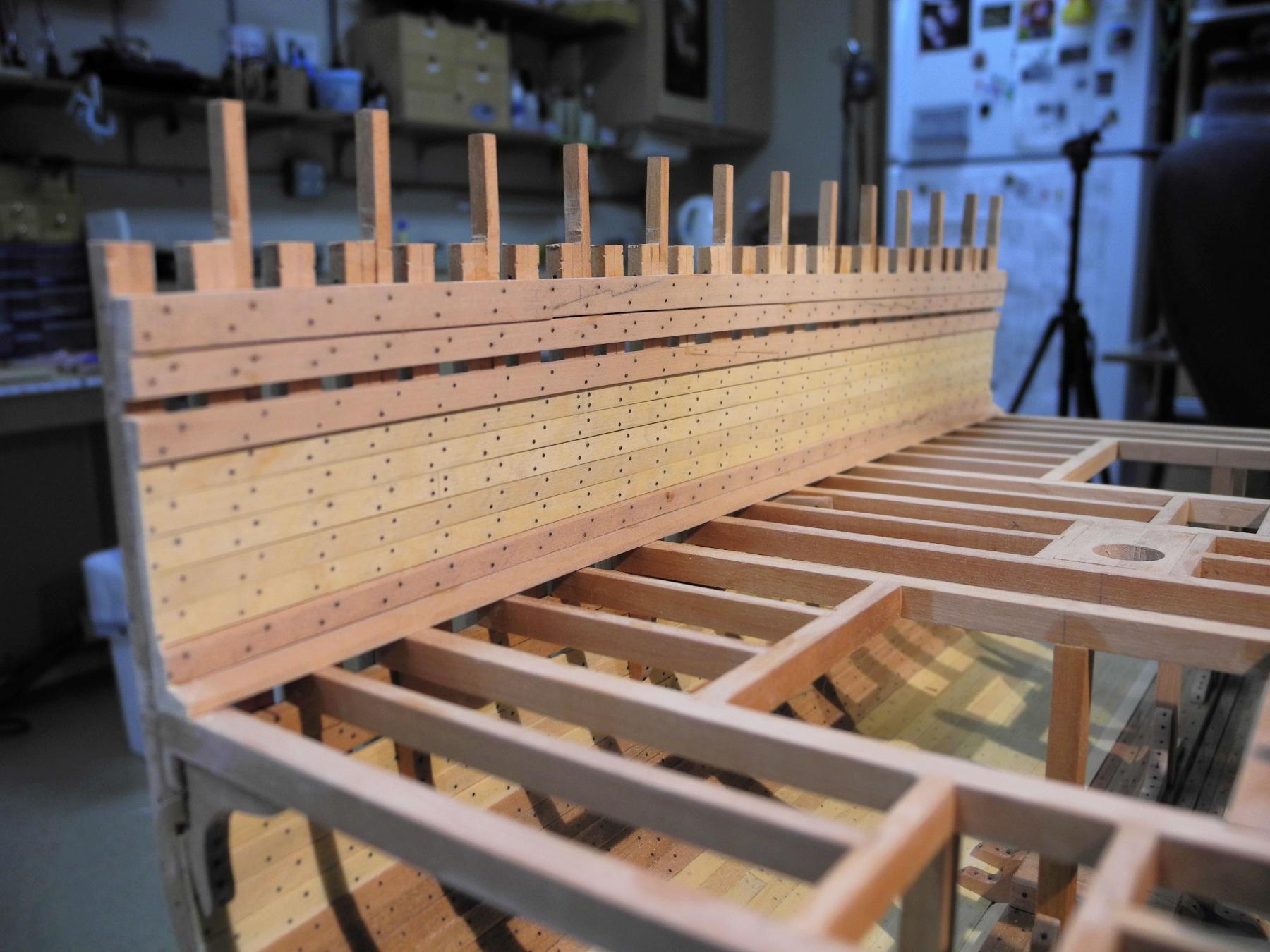
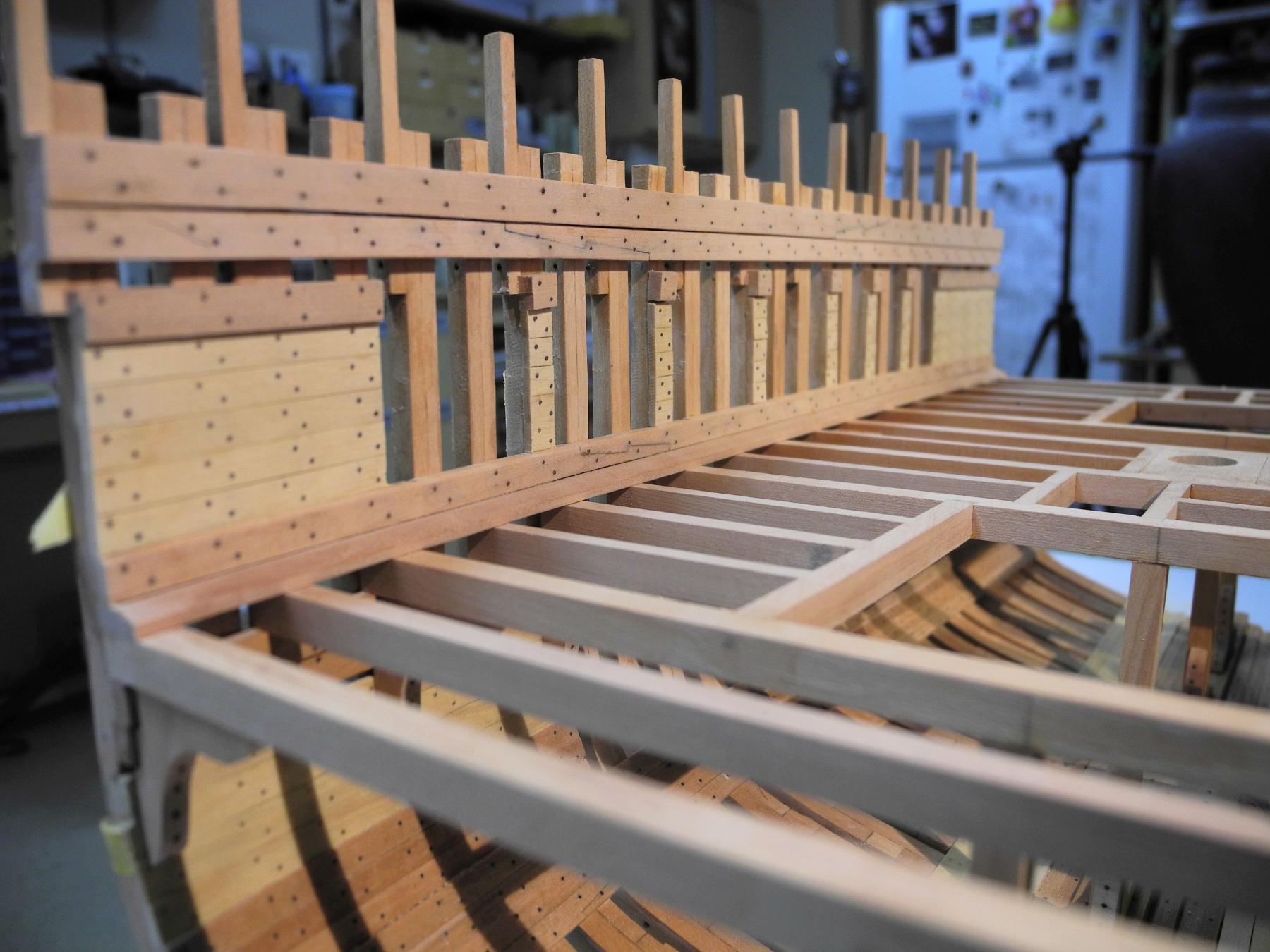
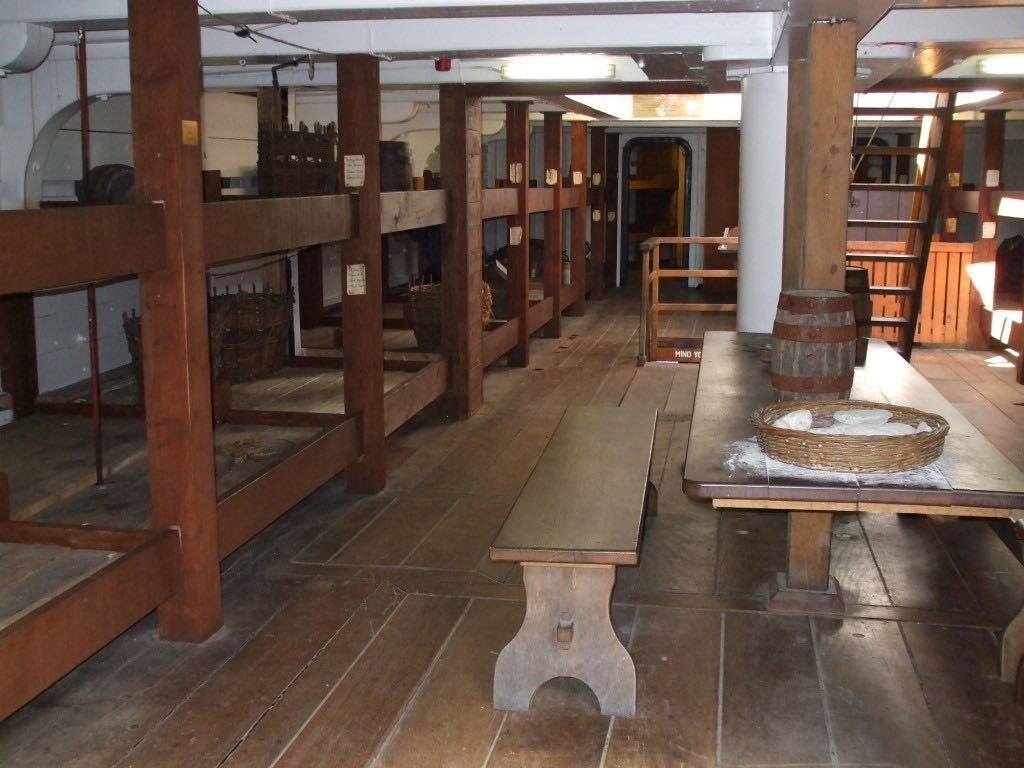
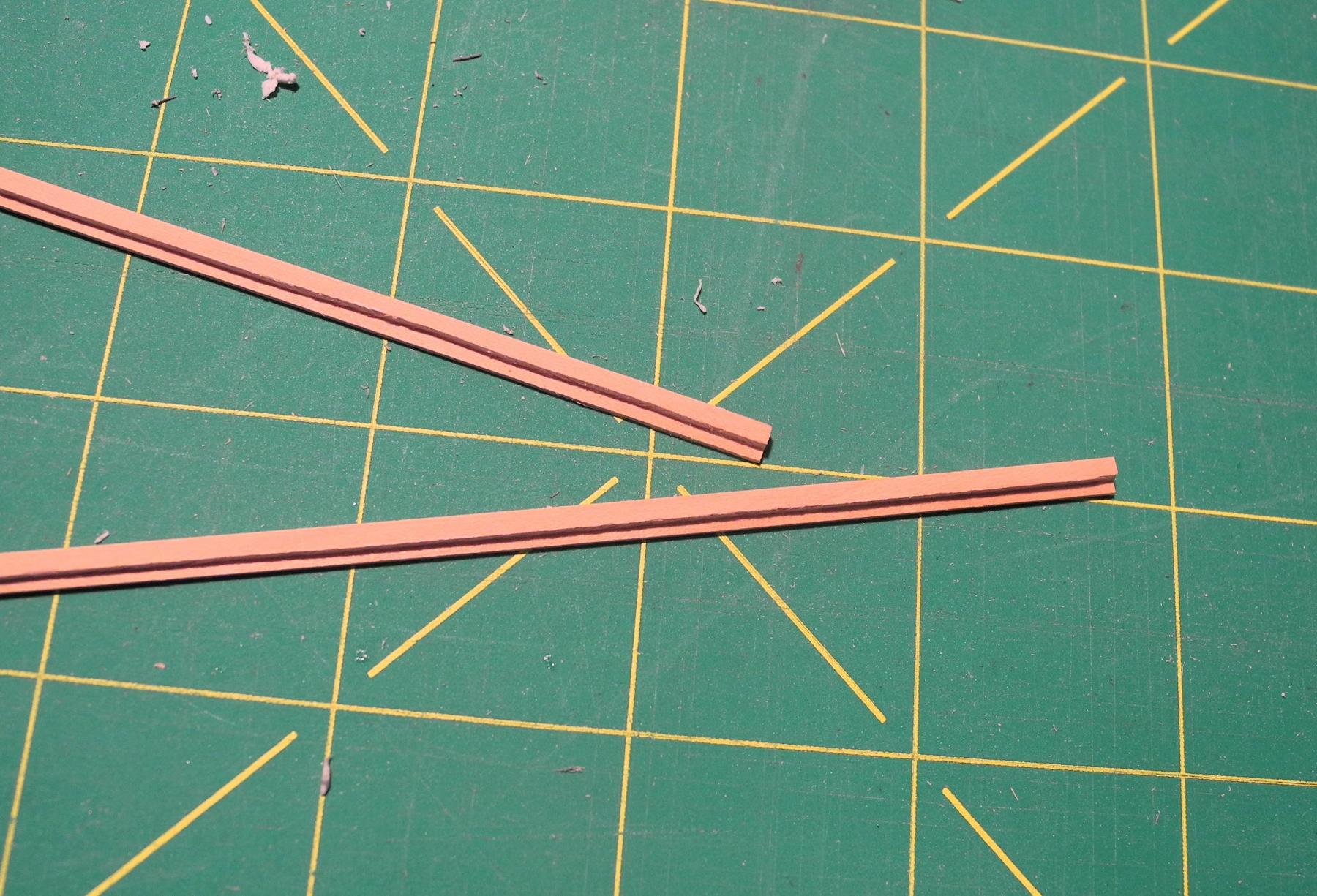
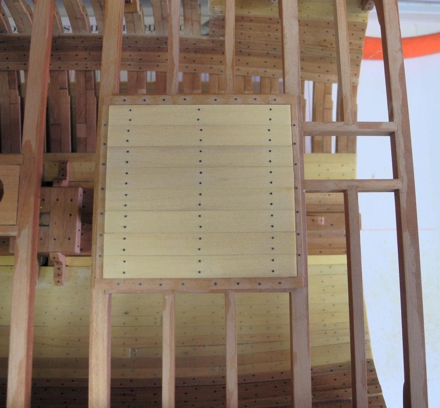
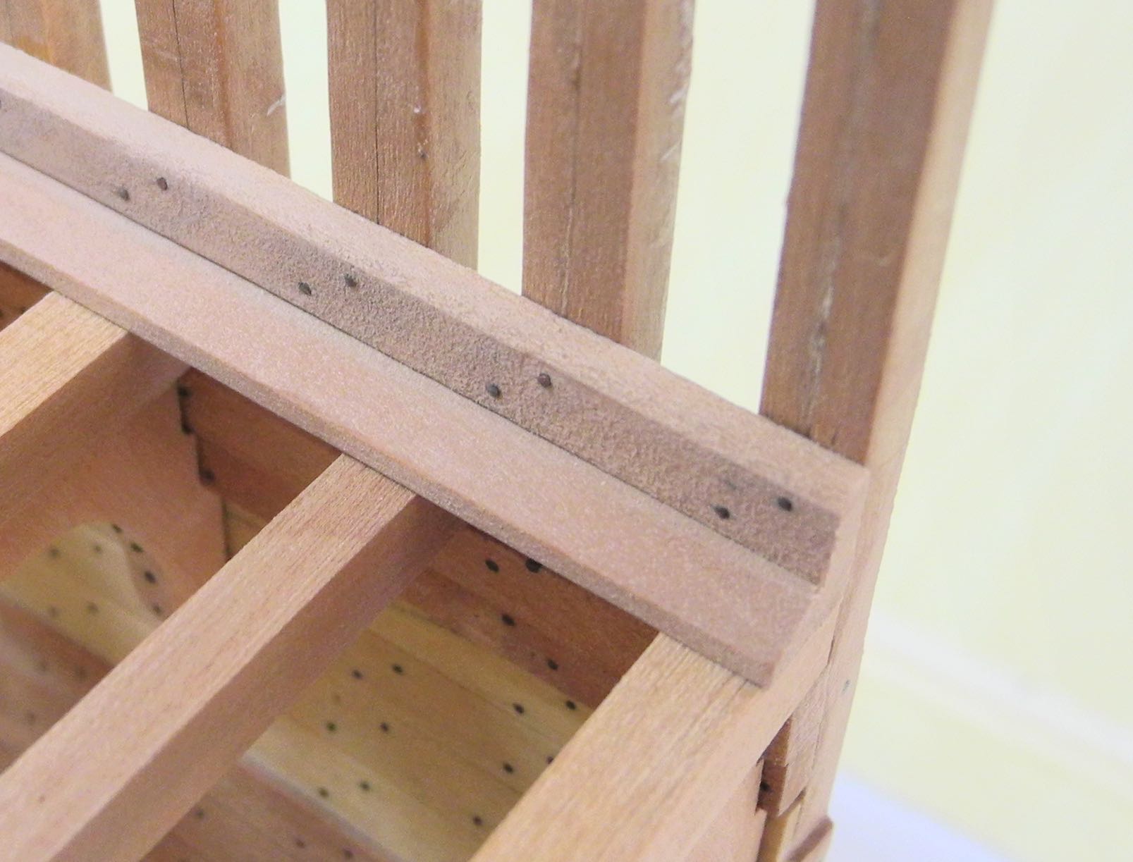
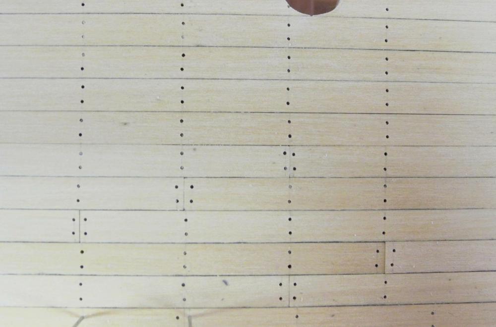
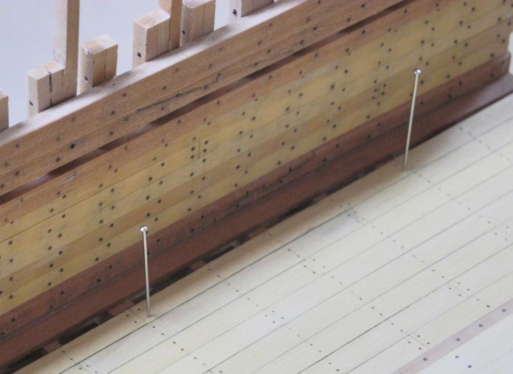
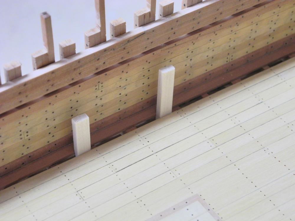
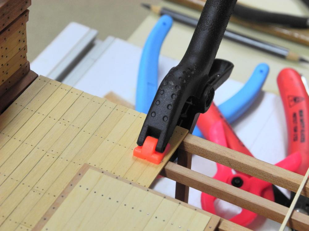
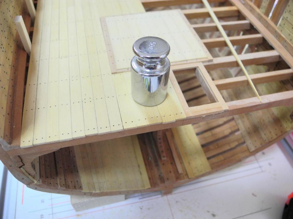
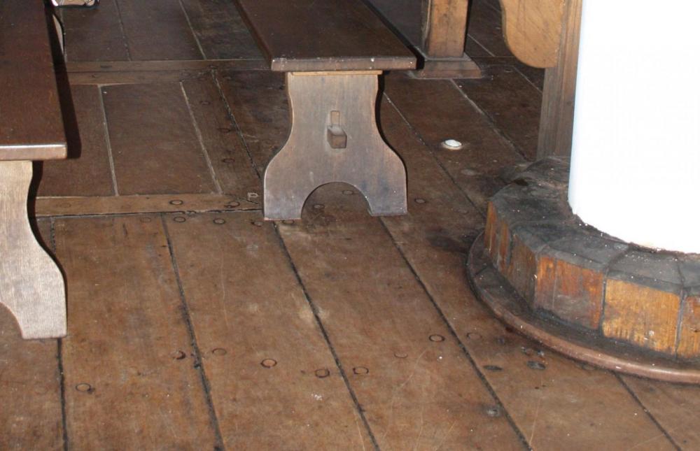
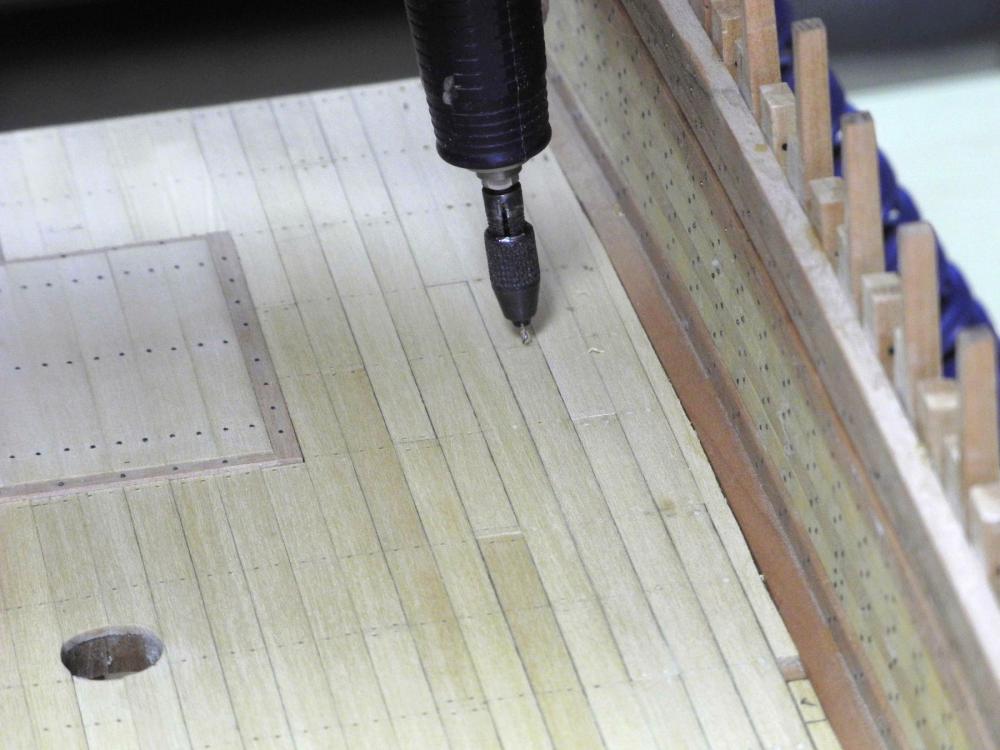
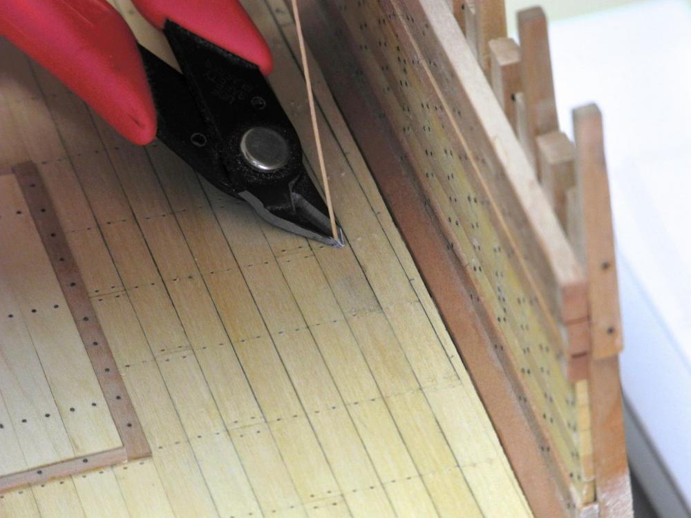
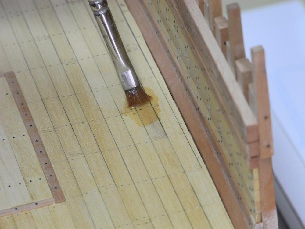
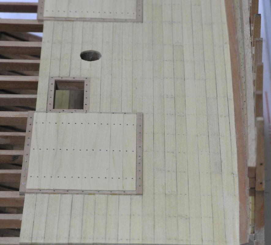
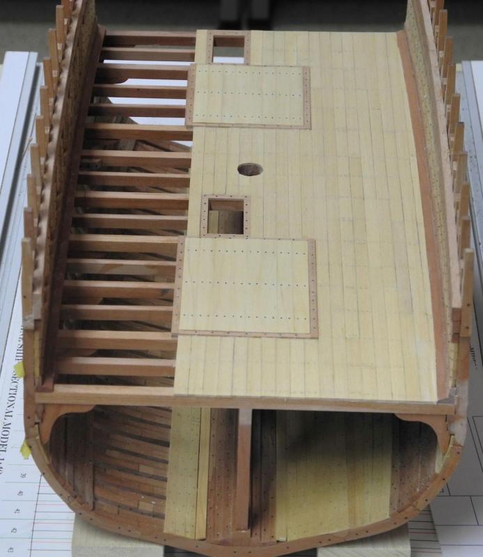
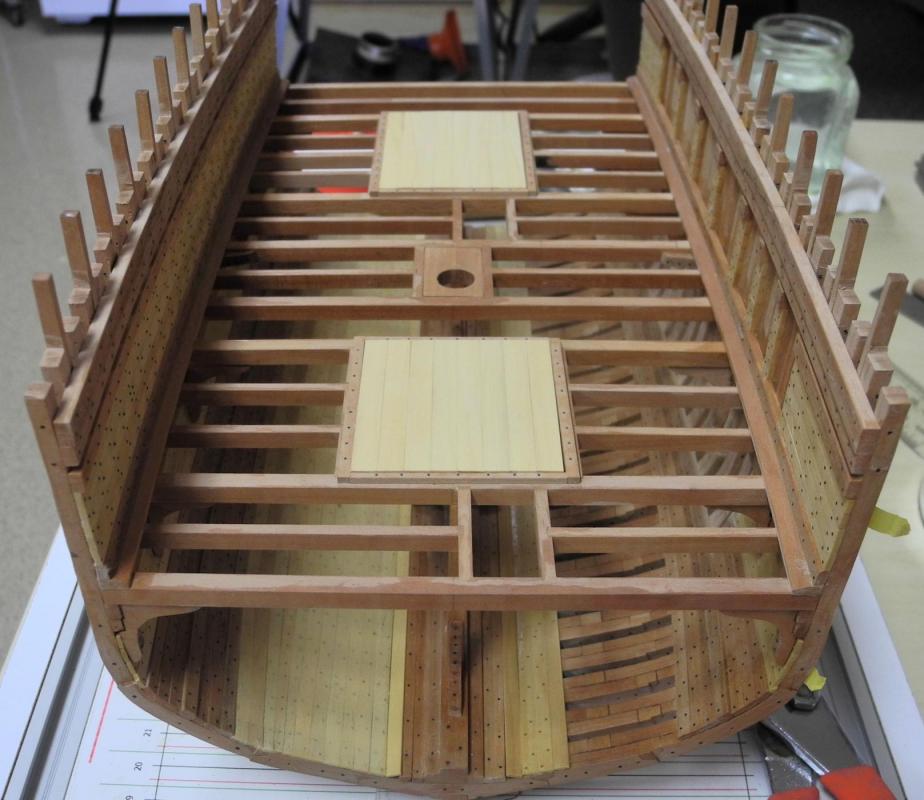
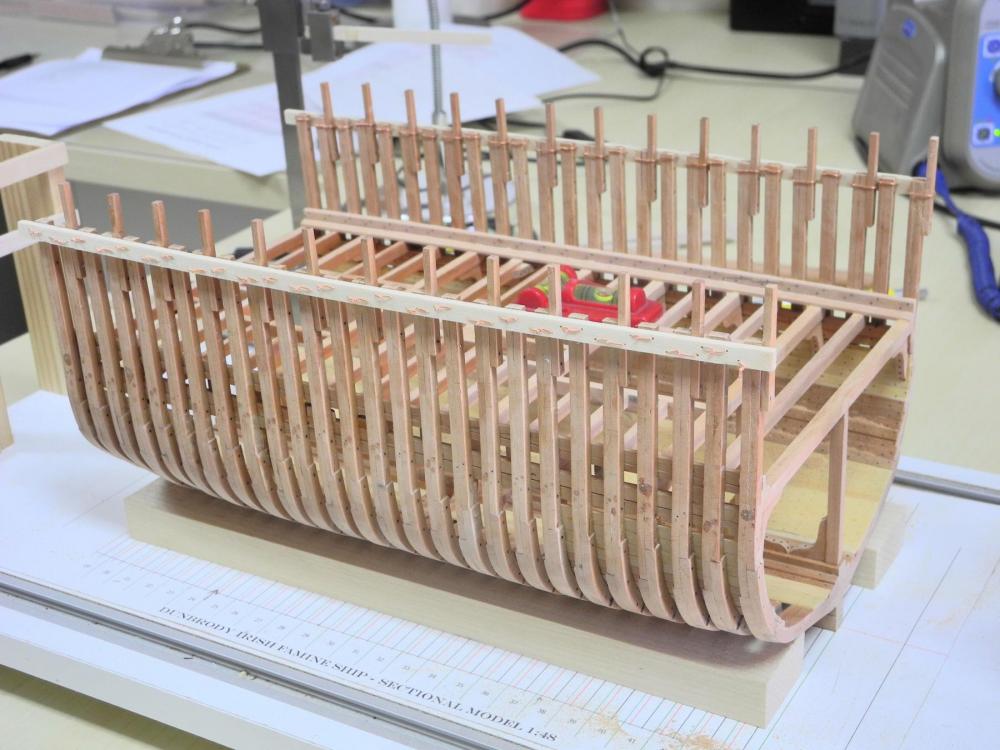
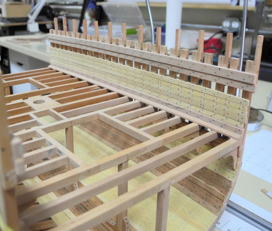
Part 31 – Accommodation Deck Planking Before starting the planking of the Accommodation Deck, the companionways needed to be framed out. I decided to use timbers that were the same thickness as the planking would be, to avoid any additional changes in the surface of the deck. I didn’t take any photos of this work, so the following photo includes some deck planking that was already under way. Deck Planking is pretty straightforward. The maximum length of the planks that I allowed was 15 feet, but most planks did not reach that long since they terminated at the midpoint of a deck beam. I measured and pre-drilled each plank before installation, so that the holes for the eventual treenails would be properly lined up. The holes that I drilled allowed me to use a .0260 pin to secure the planks. I used other methods of securing the planks in place, depending on circumstances. I used small wedges I often used spring clamps when they could reach the plank properly. I also used weights when needed. Once all the planks had been installed I then needed to drill the holes for treenails. The original holes were drilled with a #74 drill. I used a #70 to enlarge the holes for the treenails. In reality, the deck planks are not treenailed but instead are bolted or nailed and then a plug is inserted in the plank to blend with the wood of the plank, as in the following photo of Dunbrody’s Accommodation Deck. And yes, I think I need to make the mast coat with wedges – even on the Accommodation Deck. In any event, I experimented with a few methods of making the appearance of plugs, but wasn't happy with the results so I used treenails. So I spent some time re-drilling all of the planks once they were in place. I dipped the treenail in diluted glue and inserted it in the pre-drilled hole. Then clipped the treenail And finally, washed off the glue residue. I didn’t plank the entire deck, since I want to show some of the framing. I may decide to add a few more planks as work progresses and the need arises, so I haven’t applied any finish to the deck at this point. I’ll probably work at several things next: the temporary living arrangements for the emigrants, the beams for the main deck, and I’ll attempt a mast coat with wedges. So there’s some fun items ahead. Thanks again everyone.


- 649 replies
-
- 23
-

-
- dunbrody
- famine ship
- (and 2 more)
-
Thanks Patrick. I am pleased with the results thus far, and this has been a great learning experience. Thanks Ken.
- 649 replies
-
- 4
-
-
- dunbrody
- famine ship
- (and 2 more)
-
Hi Brian. That would be great. I think I'll probably be in the shop.
- 649 replies
-
- 5
-
-
- dunbrody
- famine ship
- (and 2 more)
-
Great work, Patrick. I particularly like the last photo (with the watch) - but you should have used your Rolex in the photo.
-
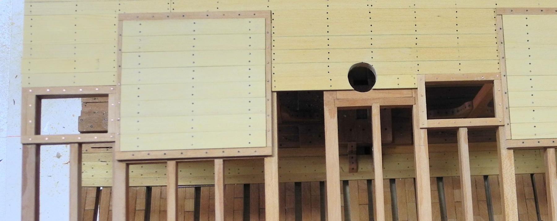
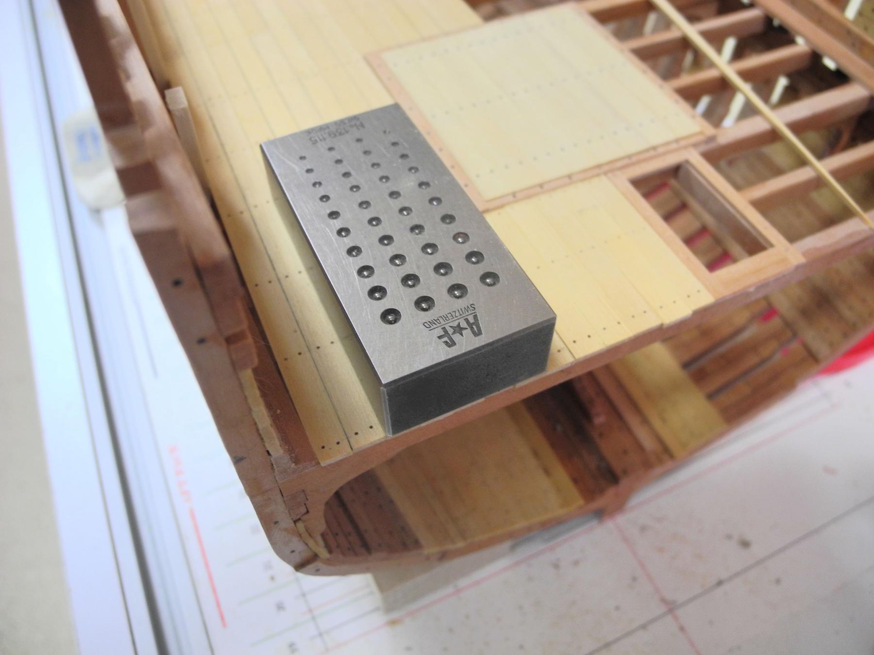
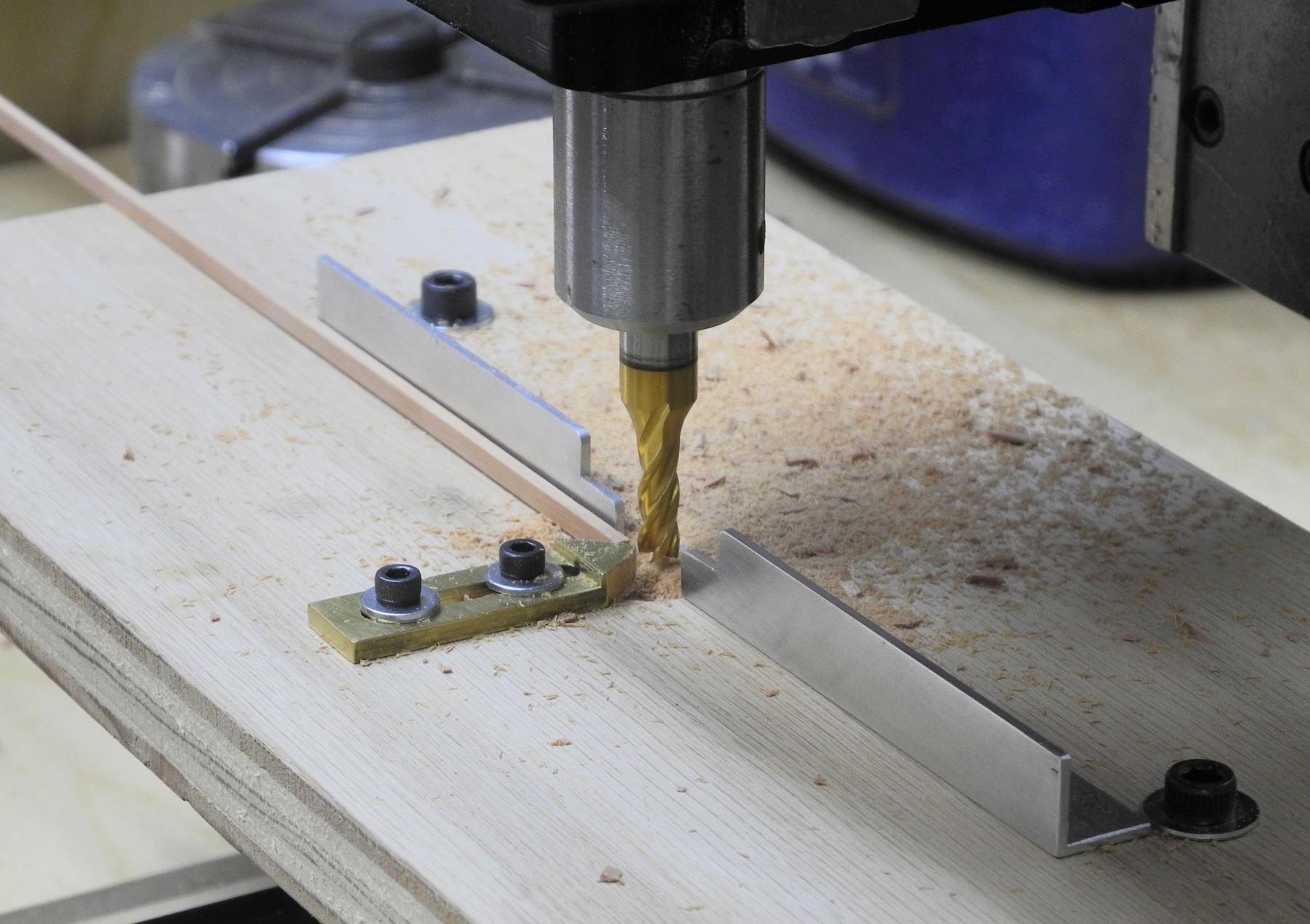
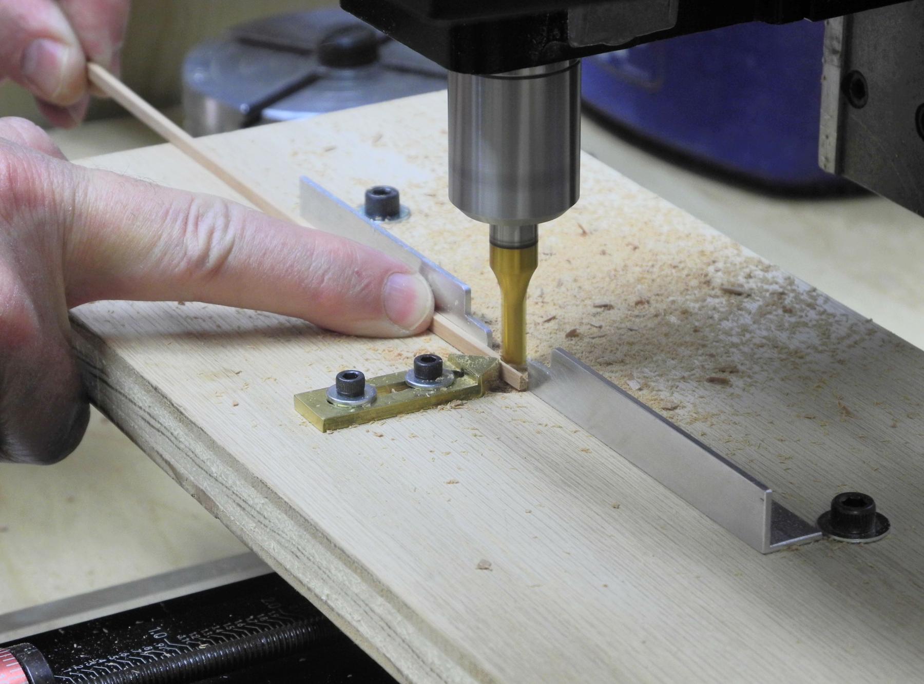
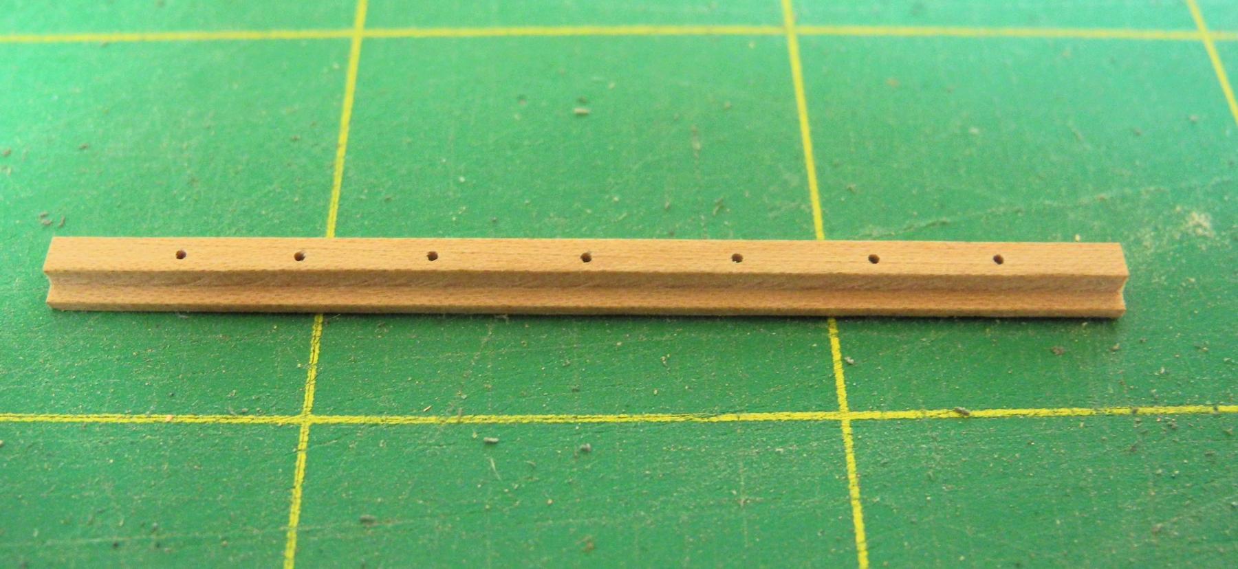
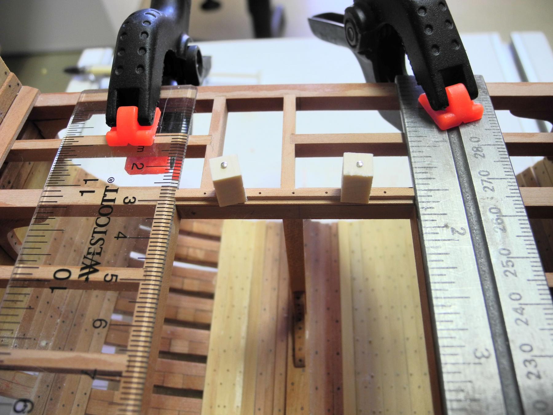
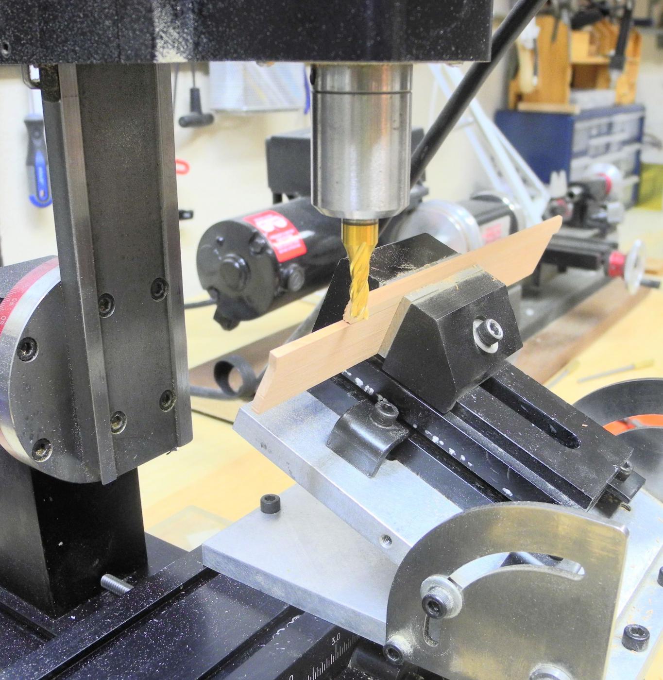
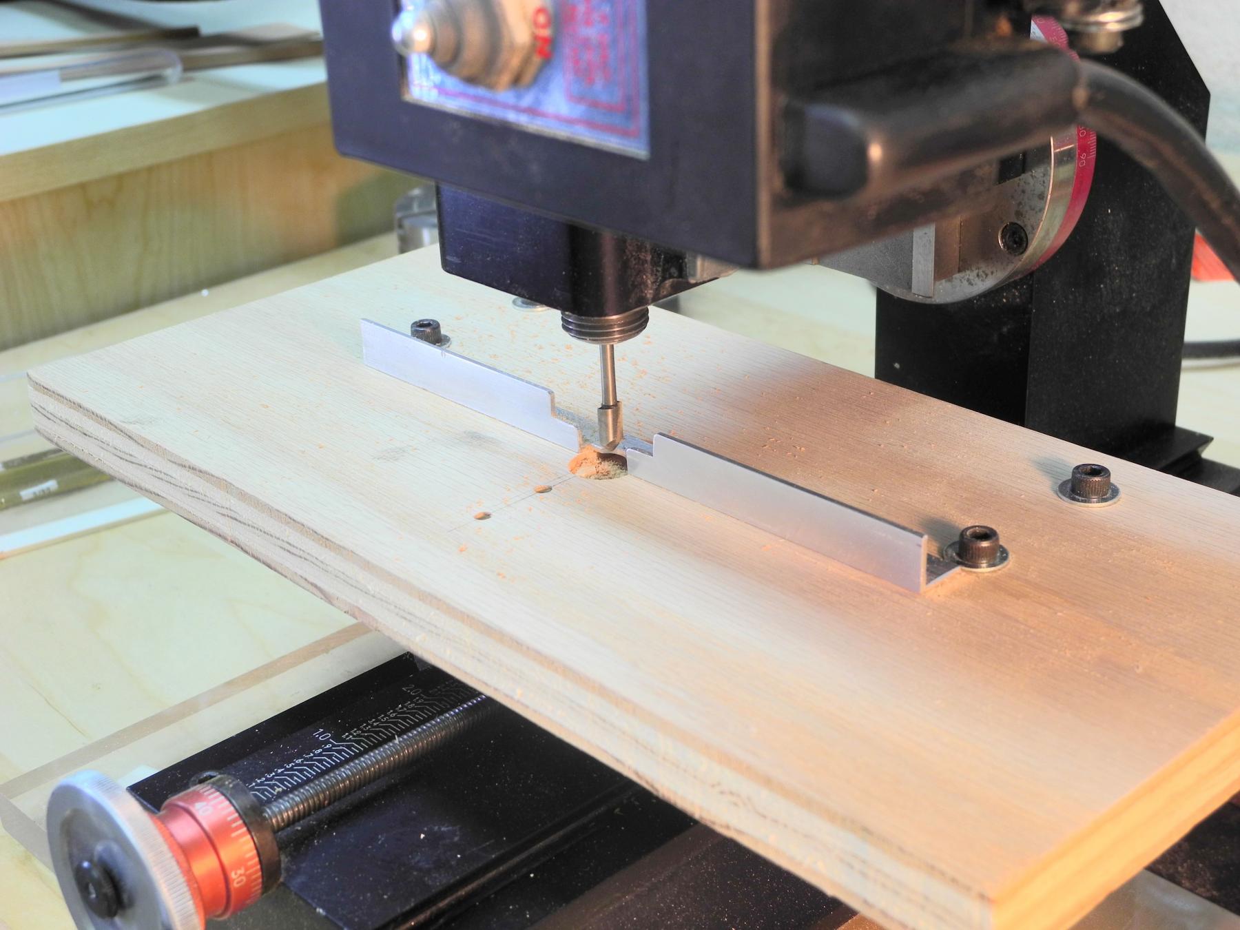
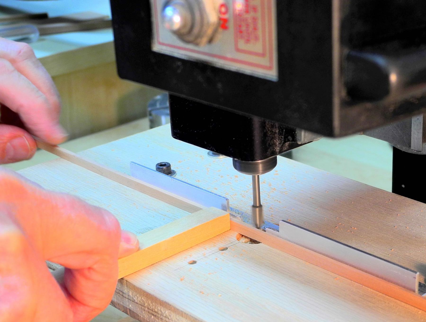
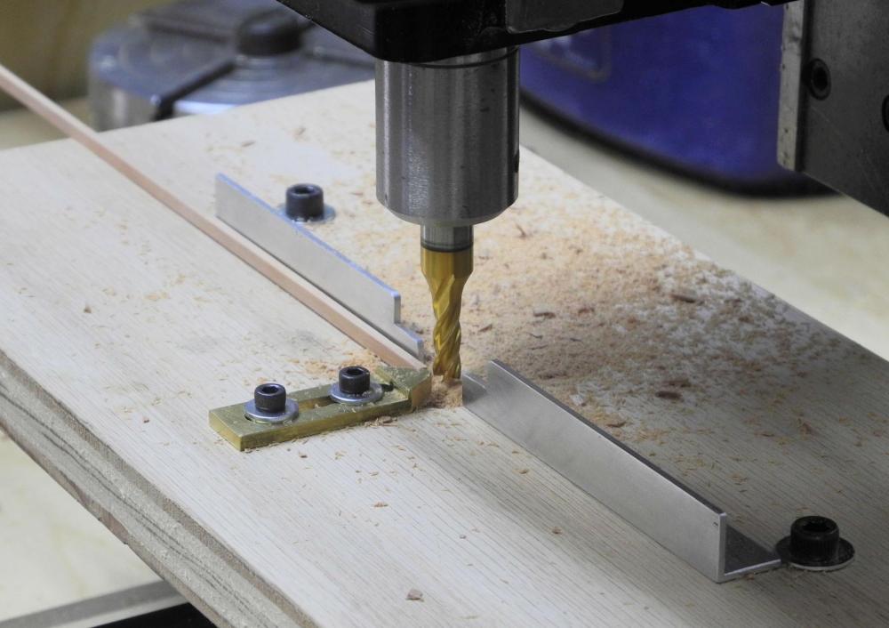
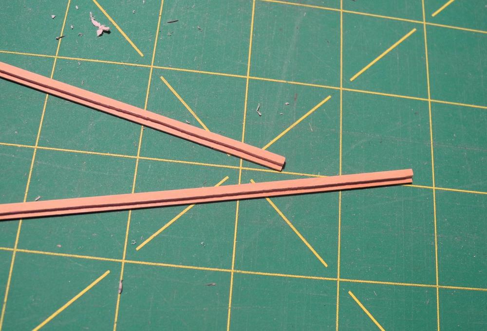
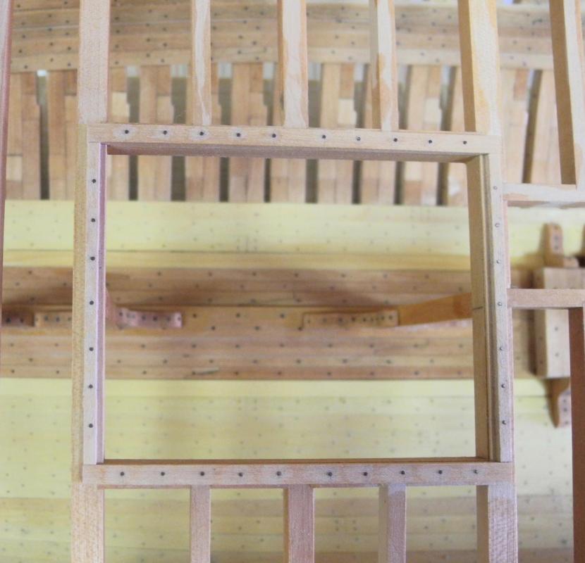
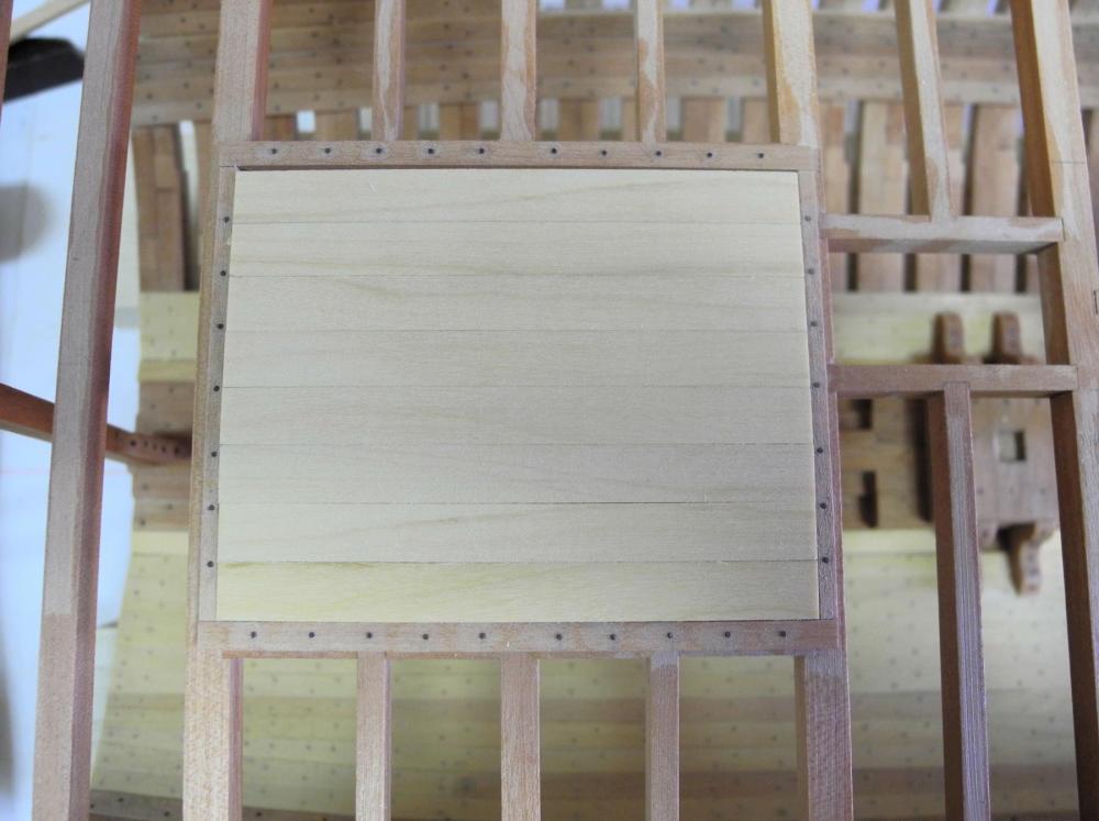
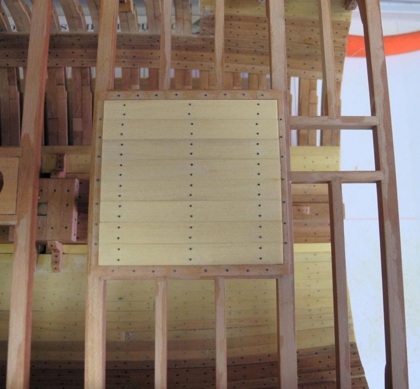
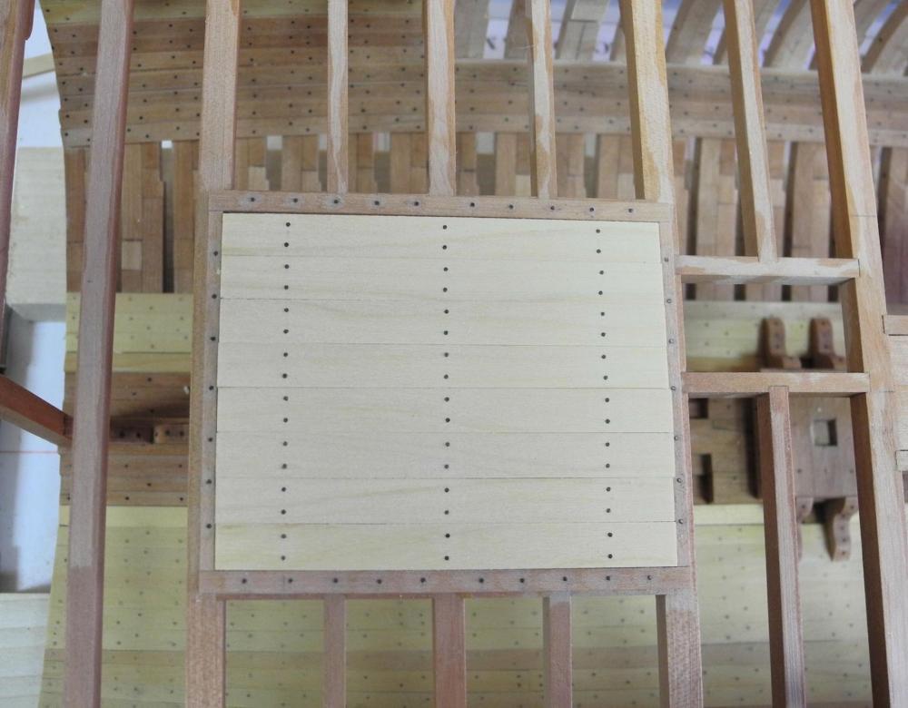
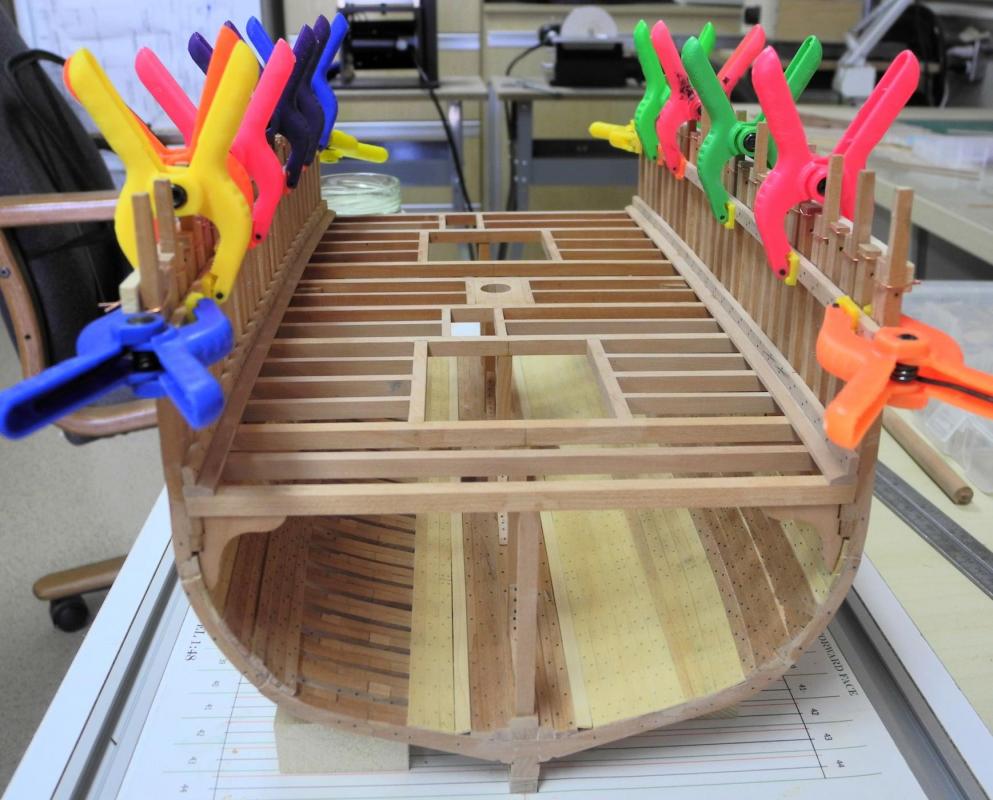
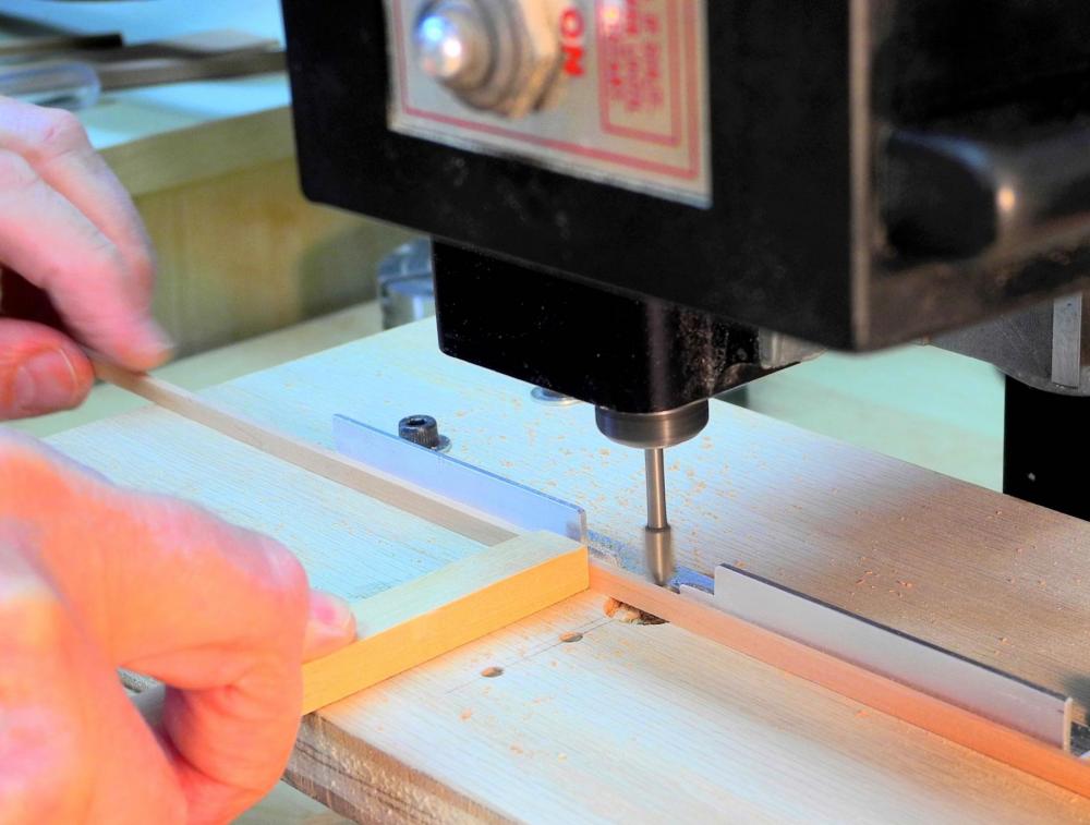
Part 30 – Accommodation Deck Hatches The last work to be done on the interior sides of the ship was the lower clamp for the main deck on the port side, and all of the partial strakes on the starboard side. The clamp on the port side, being a full-length strake with a hooked scarf joint, went fairly quickly. The starboard side, however, needed partial strakes in the 4 fore and 5 aft frames, and individual pieces on the seven frames that will (or may) be left in place after cutting the viewing ports. This work consisted of 48 individual pieces that needed to be cut, drilled for bolt holes, bolts installed and blackened, and then the individual piece needed to be installed in place and glued. After all the pieces were installed, they then needed to be trimmed using sanding sticks and/or files. In all, this consumed an entire long day in the shop. When prepping the photos I noticed a couple of pieces that need to be re-seated but I’ll wait to see if the frame they’re on will survive (additional work needed on the frame may make the decision to keep or remove the frame easier). So now the hull is completed up to the level of the main deck beams. Next up is finishing the hatches for the Accommodation Deck. Since these hatches were not exposed to weather the coamings did not need to be as massive as they would be on the main deck. Generally coamings on the tween decks were about 6 inches high and 6 to 8 inches wide, according to the Crothers book. A consideration in making these hatches was the fact that the tables and benches used by the emigrants would be partially on these hatches. In the replica ship there is an outline of a hatch on the accommodation deck, but the hatch cover is clearly flush with the deck planking. This makes sense when thinking of the replica ship, since it wouldn’t be very good if the tourists were constantly tripping over the hatch covers. I’m sure this wasn’t a consideration for the actual ship – the emigrants probably had to deal with this and many other issues (I don’t think they had funds for legal representation in case of an accident caused by deck hatches). In any event, I decided to make the hatches approximately 1 and ½ inches higher than the deck. The fore and aft hatch coamings needed a rabbet for keeping the hatch cover in place. I used the setup in the following photo for milling the rabbet. The small brass fixture in the front of the setup is designed to keep the stock pressed against the end mill. In use, I fed the stock from the left, and used a finger of my right hand to keep the stock pressed against the base of the fixture (the cutting action would otherwise cause the piece being milled to rise). I milled a few lengths of stock – more than I would need for the fore and aft coamings. When the coaming was measured and fit for the opening it was then drilled for the installation of bolts. In actual practice the coamings needed to be flush with the sides of the hatch opening so that there were no obstructions that would cause any problems during loading. I used straight edges that were clamped at the port and starboard edges of the hatch framing, and fit the fore and aft coamings between these devices. The following photo shows a coaming being pinned and glued. After the forward and aft coamings were in place the sides could be added. Another consideration in making these hatches was the nature of the cover to be used. I decided to make a set of covering boards for each hatch. Each board is approximately 12 inches wide (I used a scale measurement that brought me close to the 12 inches while not requiring any partial boards. The hatch covers then needed bolting patterns, since there was a framework under the boards that formed the boards into a single hatch cover. The astute viewer (GuntherMT) will probably notice that the hole pattern in the top board of the first photo is off. This is because the boards were still loose and laid in place for the photo and I didn’t notice at the time that I had one board reversed. This will be corrected in the final installation. I’ll add some lifting rings for the hatch covers at a later time. The poor emigrants will need to be careful not to trip over those as well. Now on to the deck planking and the borders for the companionways. Once that’s completed I’ll start working on the actual ‘accommodations’ for the emigrants.


- 649 replies
-
- 23
-
-
- dunbrody
- famine ship
- (and 2 more)
-
Thanks Ed. I think you're seeing the effect of parallax. I hand held the camera and tried to get things properly lined up, but obviously didn't. I will double-check, though, later today.
- 649 replies
-
- 4
-
-
- dunbrody
- famine ship
- (and 2 more)
-
Thanks Patrick. Thanks Druxey. Yes, now I feel like I'm making some progress.
- 649 replies
-
- 4
-
-
- dunbrody
- famine ship
- (and 2 more)
-
Hi Brian. No, I'm only going to make a stub for the mast. There may be some rigging fixtures like deadeyes, etc, but no lines (at least not for now).
- 649 replies
-
- 4
-
-
- dunbrody
- famine ship
- (and 2 more)
-
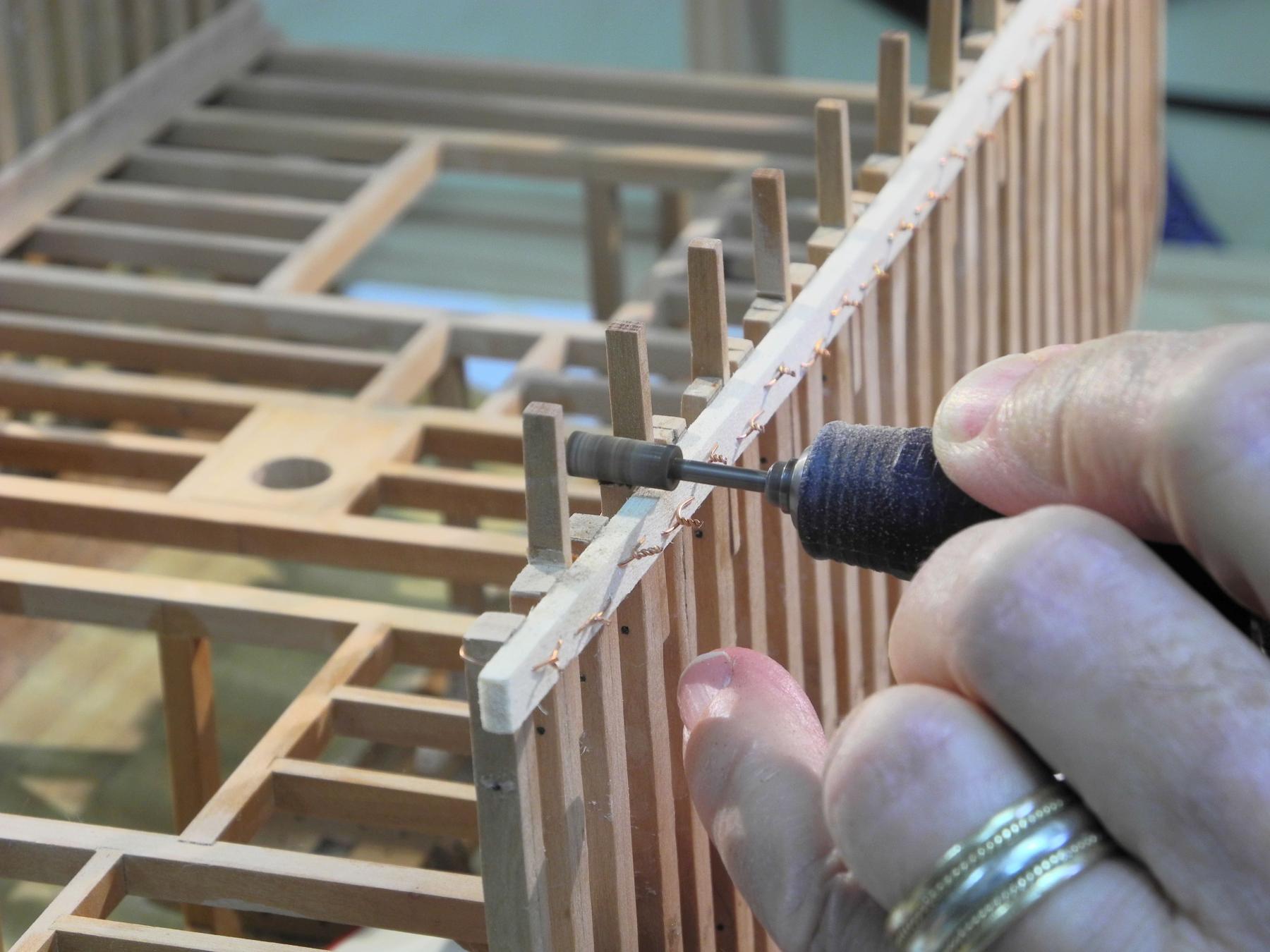
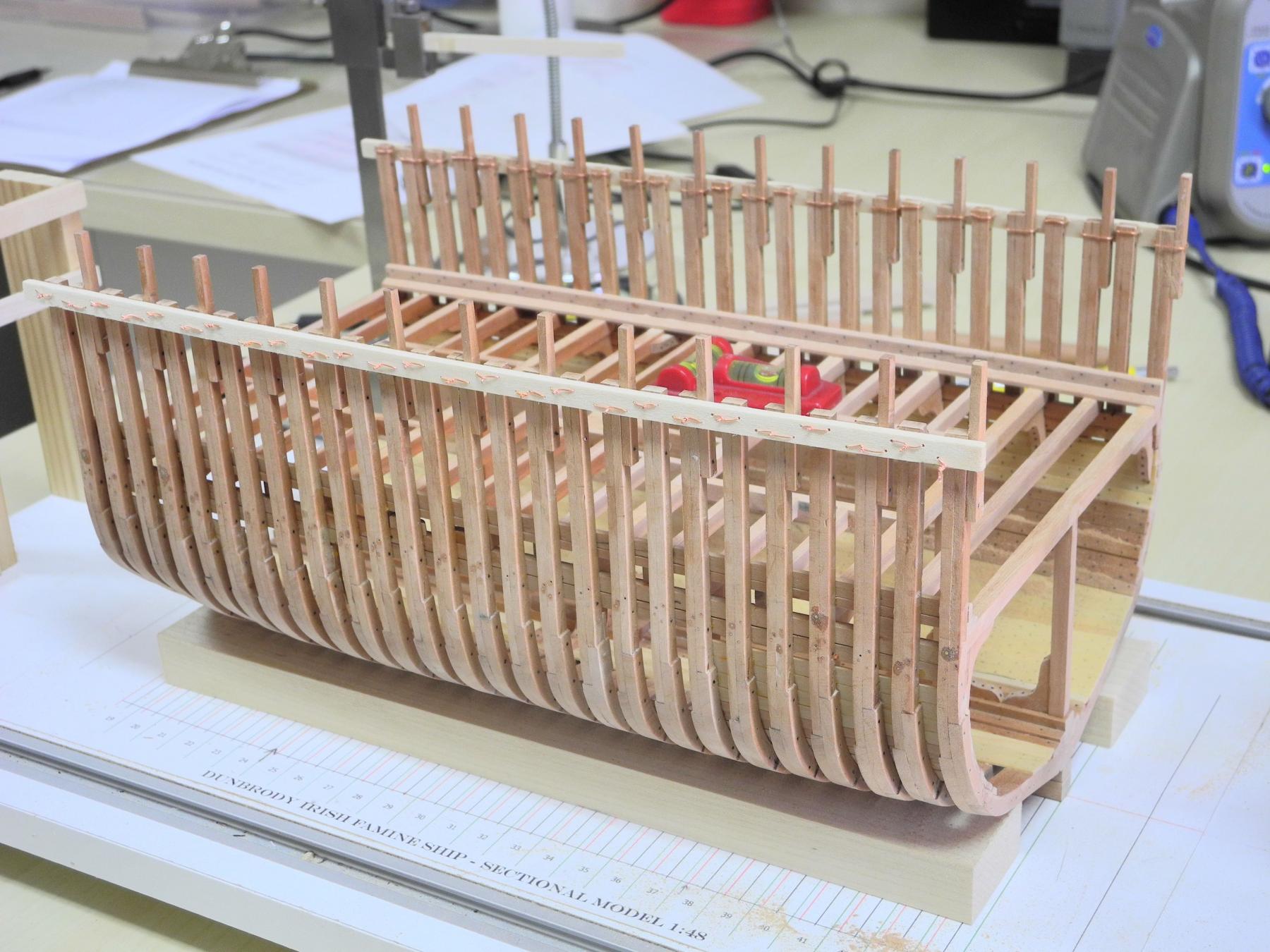
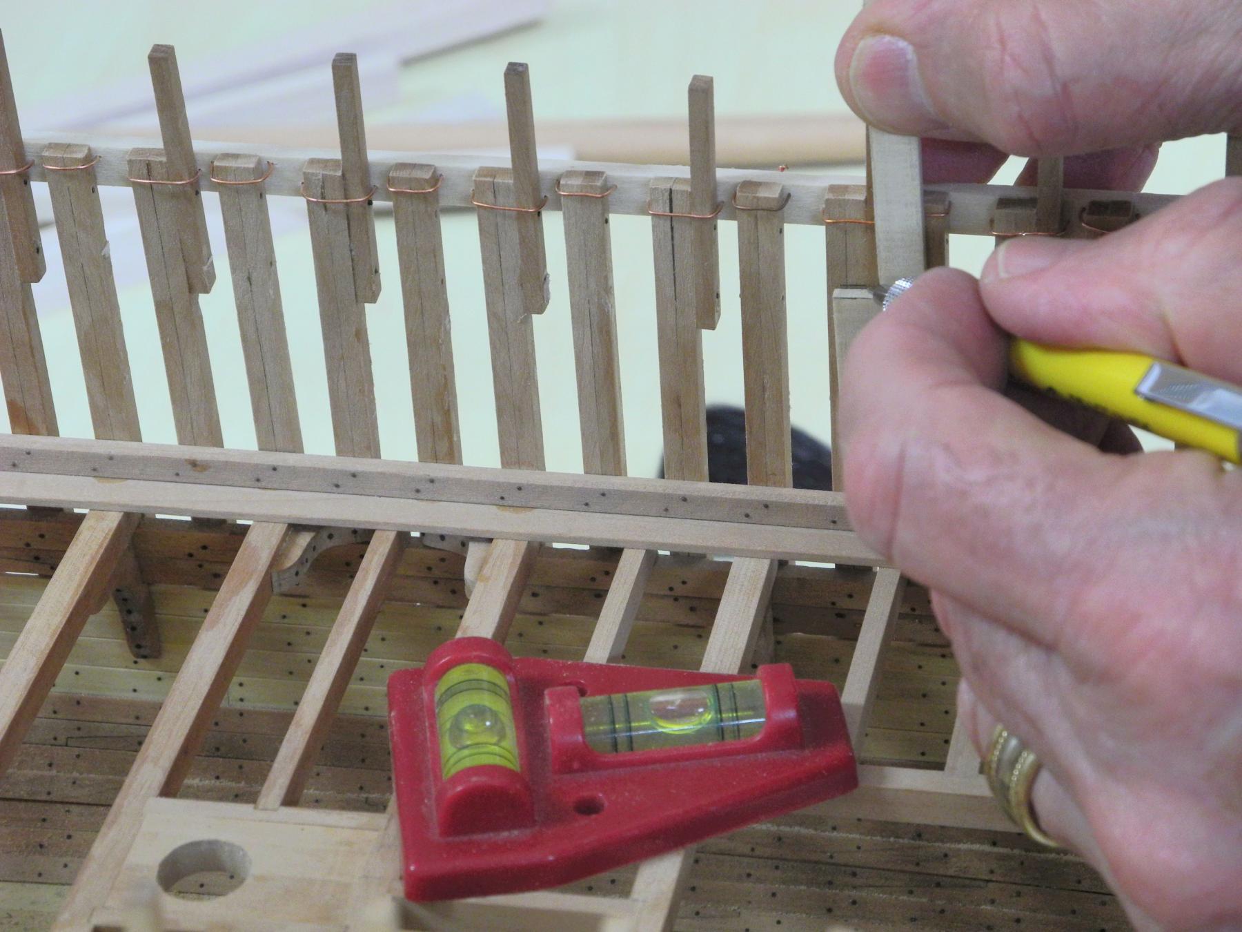
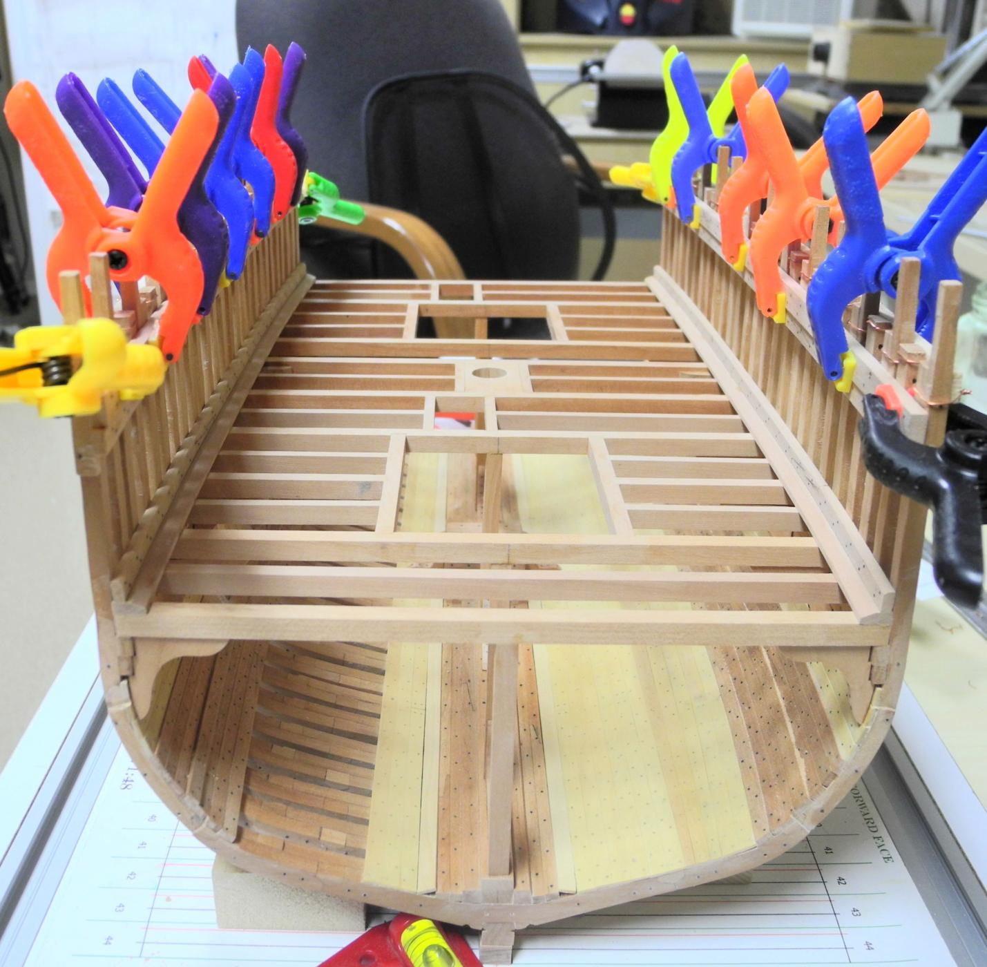
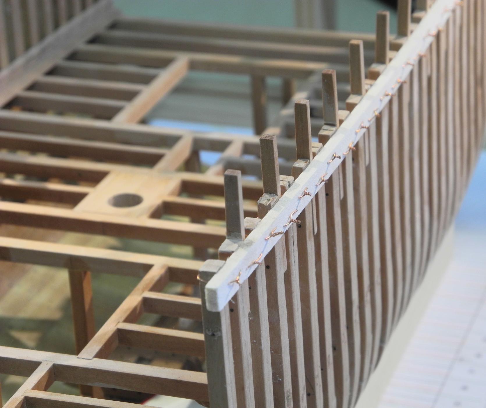
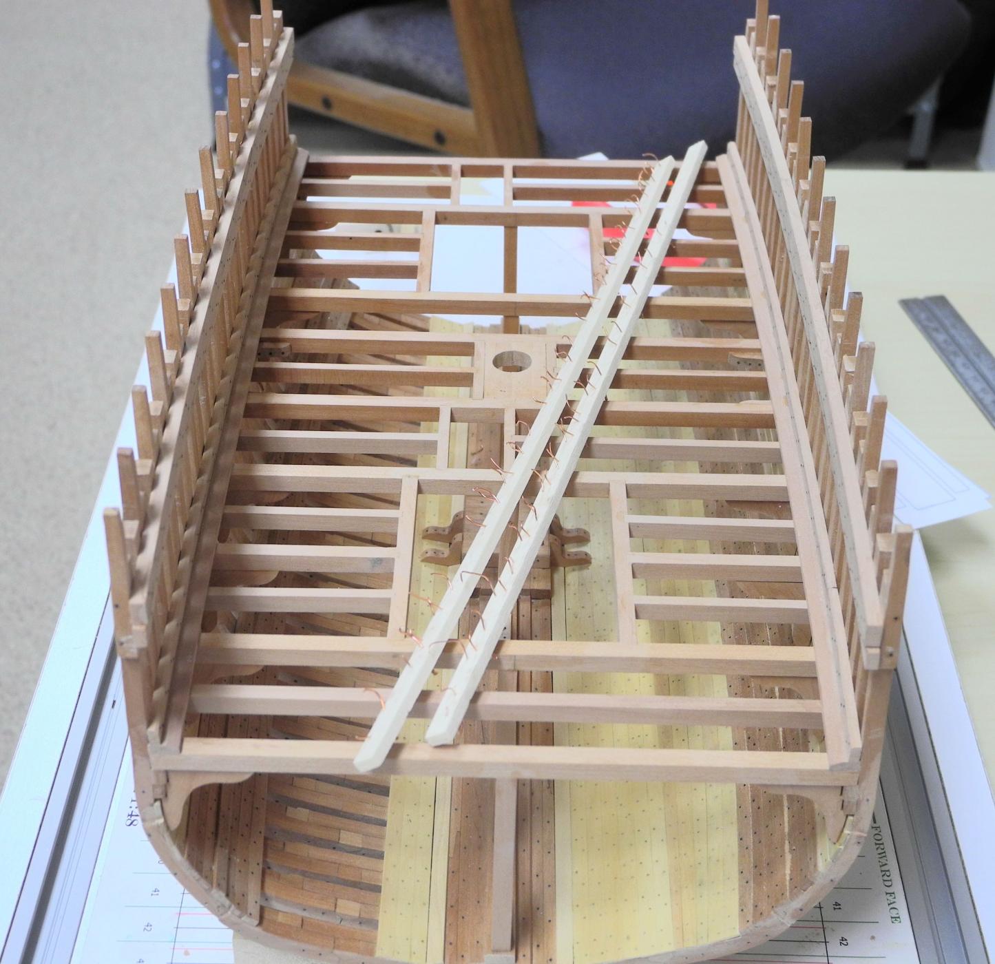
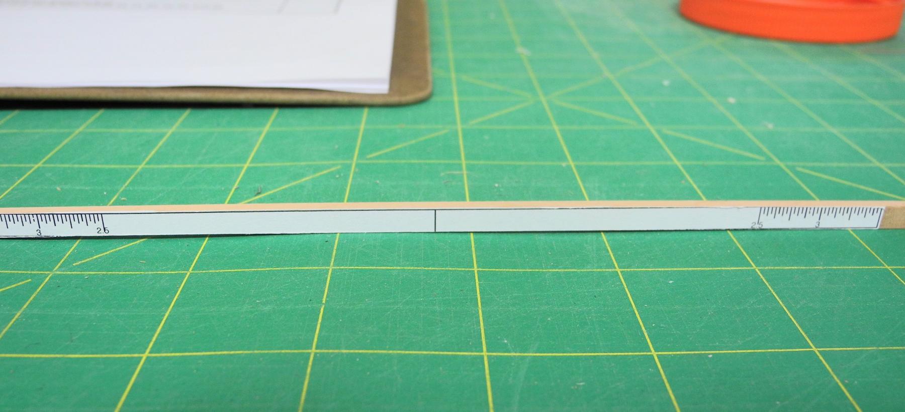
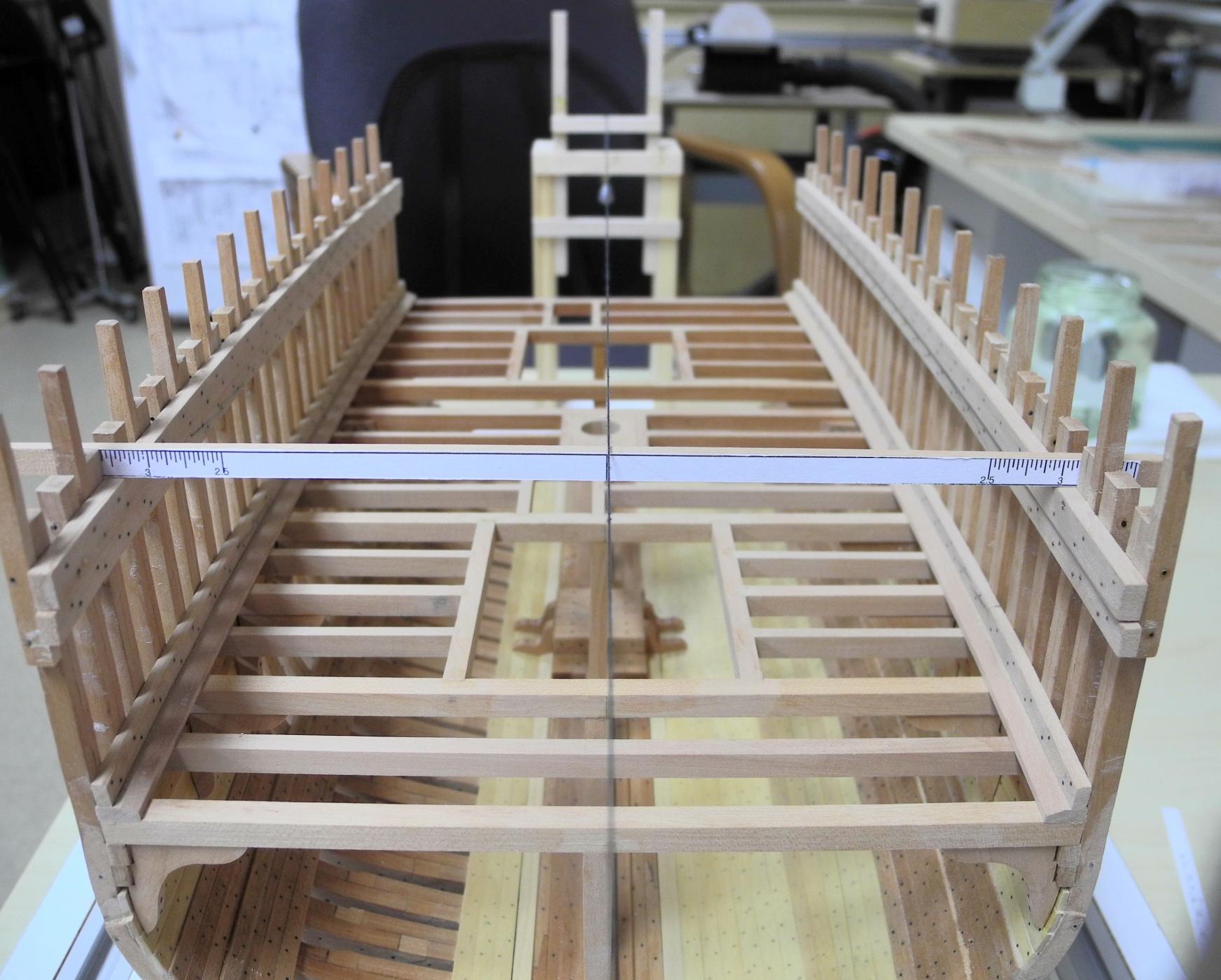
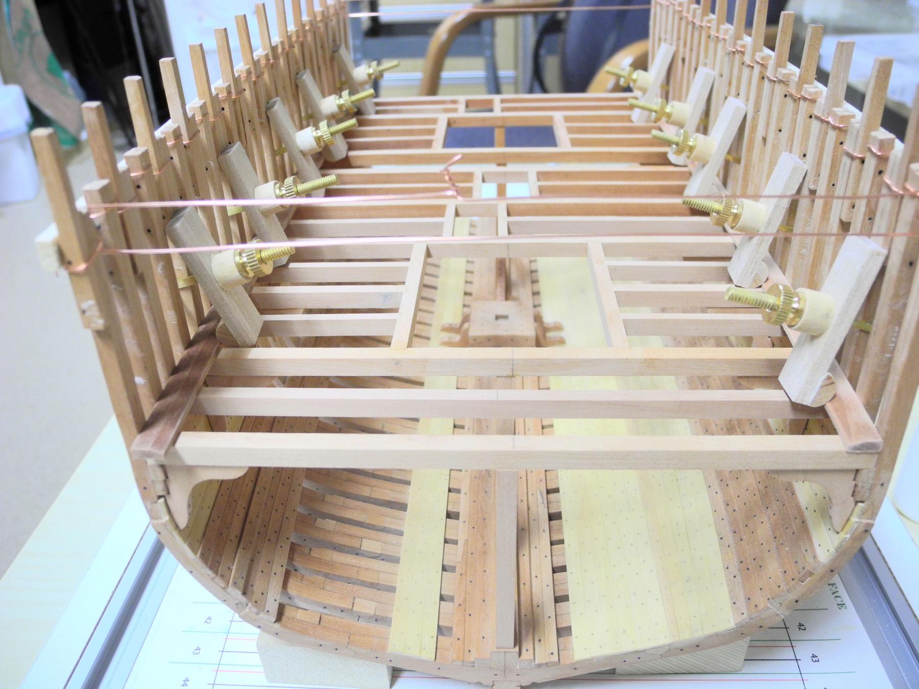
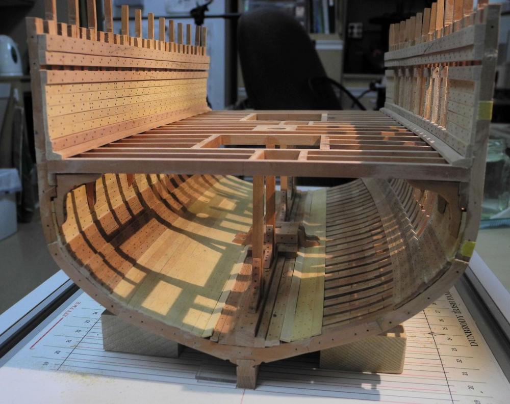
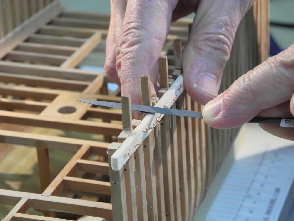
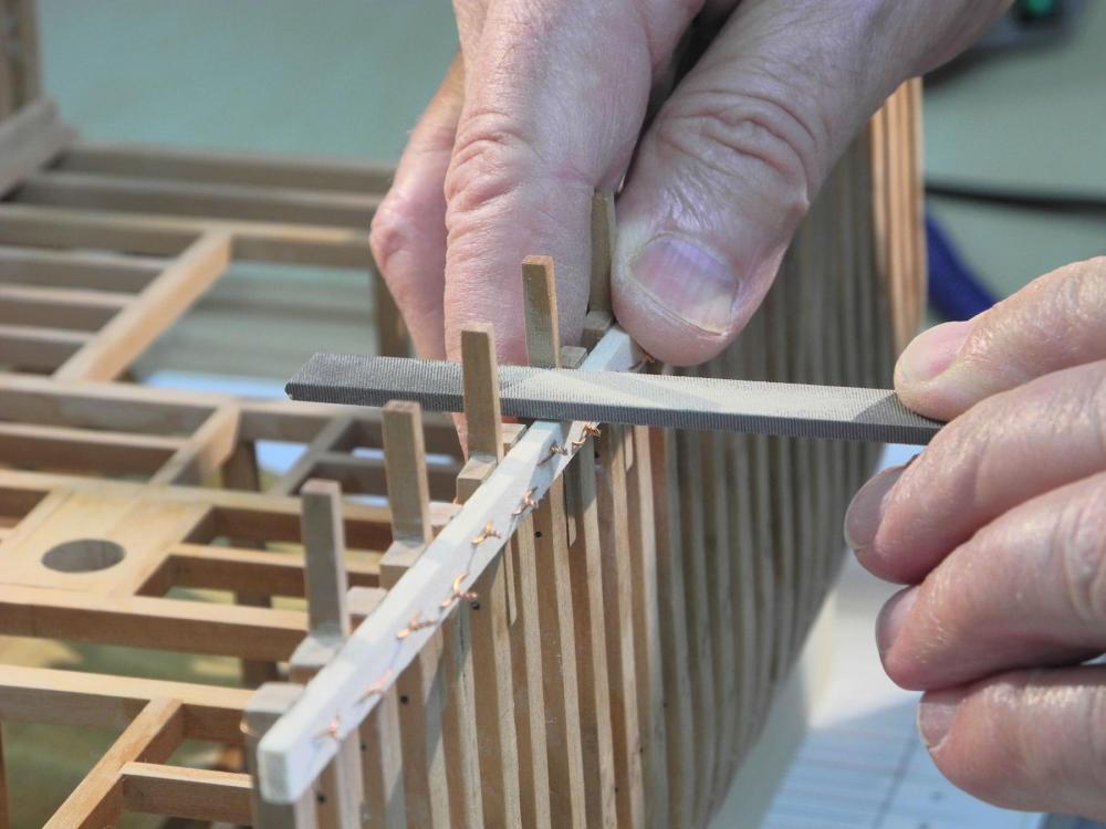
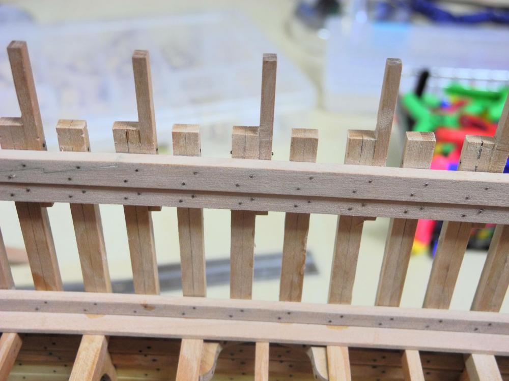
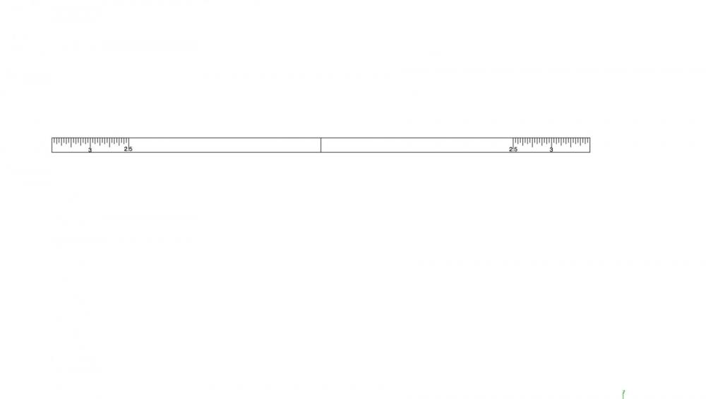
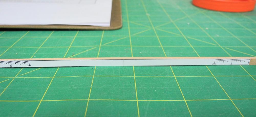
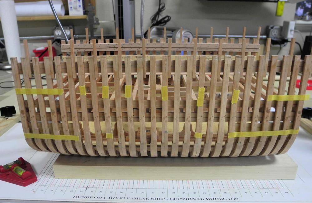
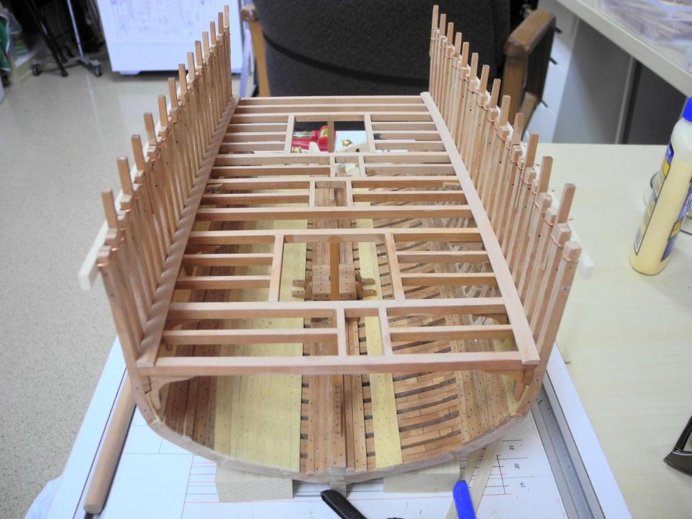
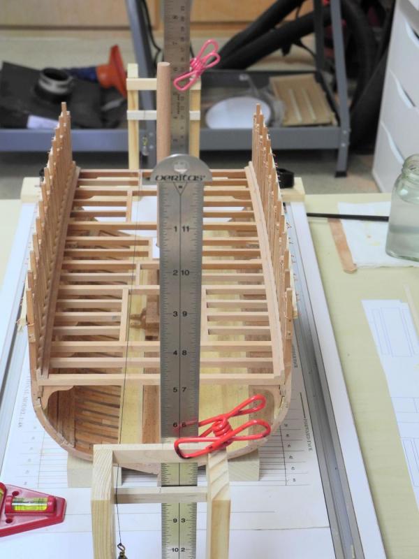
Part 29 – Main Deck Clamps and Shelf I’ve decided to continue on with the interior sides of the ship before working on any details of the Accommodation Deck. The frames were left oversized during the installation, so they needed to be reduced to their final height. Before any of the reduction work was done, the planksheer height was re-measured and a corresponding line was drawn on each frame. Reducing the height of the frames meant the removal of as much as ¼ inch of wood on some frames. The frames were too close together to use any of the saws that I had available, so I used other tools: Where I could do so without risking any damage to the frames or the associated stanchions, I carefully ground down the height using a stump cutter on a rotary device. The stump cutter removed a lot of the extra wood, but a ‘kinder, more gentle’ approach was needed to bring the frames down to their proper height. A 00 cut Barrette file was able to do a good job of wood removal, but the sides were quite sharp and ran the risk of scoring the stanchions, since the excess wood needed to be removed right to the stanchion. I tried using a larger pillar file, which had one blank edge. This edge was thick enough that it did not score the stanchion and I was able to remove the frame wood right up to the stanchion. So my process evolved to removing as much as was safe with the stump cutter and then filing away the rest of the wood with the pillar file. After several hours of tedious work the frames were all at the proper height. The Main Deck is supported by two clamps and a shelf on each side. The two clamps are separated by an air strake, so I don’t know what the purpose of the lower deck clamp is. Nevertheless, in keeping with the plan to build Dunbrody as depicted in the construction plans, I decided to install both clamps. The first of these timbers to be installed were the upper deck clamps, so I made a measuring stick at the correct height for the top of the clamp, and marked all of the frames using that device as in the following photo. The clamps were each made of two pieces joined by a hooked scarf, were soaked in boiling water and bent by clamping them in position until dry. Simulated bolts were marked, drilled, and installed using 22 gauge copper wire that was work-hardened. The clamps were then glued in place. A similar process was then followed for the main deck shelves. Even though much of the starboard side will be left open, clamps and shelves were installed on both sides to ensure the strength of the hull. Once the clamps and shelves had dried overnight, I then felt comfortable in removing the temporary ribbands that had been in place since the framing was completed. These ribbands were connected to the frames using wires (which had become pretty annoying as I scratched my arms on them whenever I needed to reach inside the hull). Removing the ribbands was a simple process of snipping the wires. Dunbrody now looks like a real ship’s hull. The device that held the string used to mark the centerline was too short to mark the centerline at the main deck, so I extended the device to allow the centerline to be approximately 1/16 inch above the deck beams. In the prior post I mentioned that the opening for the mast partners was slightly off-center. When I drew the plans for the Accommodation Deck I made the incorrect assumption that the frames were all properly centered. In fact, the starboard side is farther from center than the port side is. In drawing the plans for the Main Deck, I need to account for this discrepancy whenever there is a connection between the decks (as in companionways, hatches, and mast partners), but I wanted the plans to also reflect the actual state of the construction. I needed a device to measure the distance from the centerline to the side for each deck beam, and any rulers that I had were too big to properly measure these distances. So I used CAD to draft a centering ruler, which I then glued to a piece of stock slightly thinner than the height of a deck beam at the crown of the round-up, or deck camber. I used this device by aligning the center of the device with the centerline thread while resting the device on the two deck shelves, and then reading off the distance for each side. After recording the distances for each deck beam I’ll be able to draw a more accurate plan. The last bit of the completed work is the installation of the filling strakes on the port side. I still need to install the lower deck clamp on the port side, and all partial strakes on the starboard side. The partial strakes will be installed on the frames bordering the viewing ports and on the individual frames left in place to support the hanging knees associated with the main deck’s beams. The yellow tape in the following photo of the starboard side indicates those frames that will be left in place. Dunbrody is progressing nicely, and fairly soon I’ll be able to start finishing off the Accommodation Deck. Then the interesting work of building the emigrants’ facilities can be started. Once again, thanks everyone – for following, for the ‘Likes’, and for the comments and assistance.


- 649 replies
-
- 21
-
-
- dunbrody
- famine ship
- (and 2 more)
-
Thanks Druxey - that will put the top of the stub a little above the highest furniture (a companionway), so it should look good.
- 649 replies
-
- 3
-
-
- dunbrody
- famine ship
- (and 2 more)
-
Thanks Glenn. Likewise, I'm really enjoying your Heroine build.
- 649 replies
-
- 3
-
-
- dunbrody
- famine ship
- (and 2 more)
-
Looks great, Brian. Thanks for posting the tutorial.
-
Thanks Druxey. I'm trying to decide how far above the main deck to project the mast stub. Any suggestions?
- 649 replies
-
- 4
-
-
- dunbrody
- famine ship
- (and 2 more)
-
Thanks Brian. You're always welcome to drop by. We'll be leaving for a little vacation around July 20, so it needs to be before then.
- 649 replies
-
- 4
-
-
- dunbrody
- famine ship
- (and 2 more)
-
Nice work Brian. I've started to use card stock for lots of templates and such - much better than paper. I found that I can feed 80 pound through my inkjet printer with no problems. I'm surprised at the decks warping. Next time you come over bring a piece of decking so I can see what you're dealing with.
-
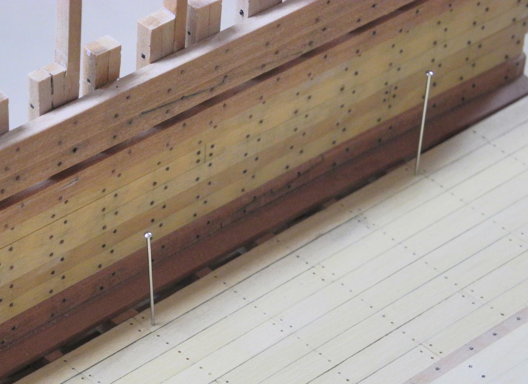
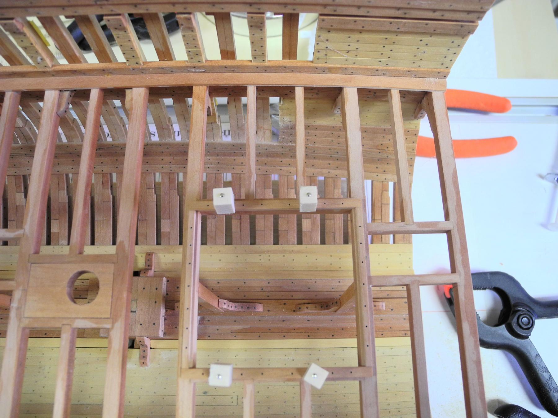
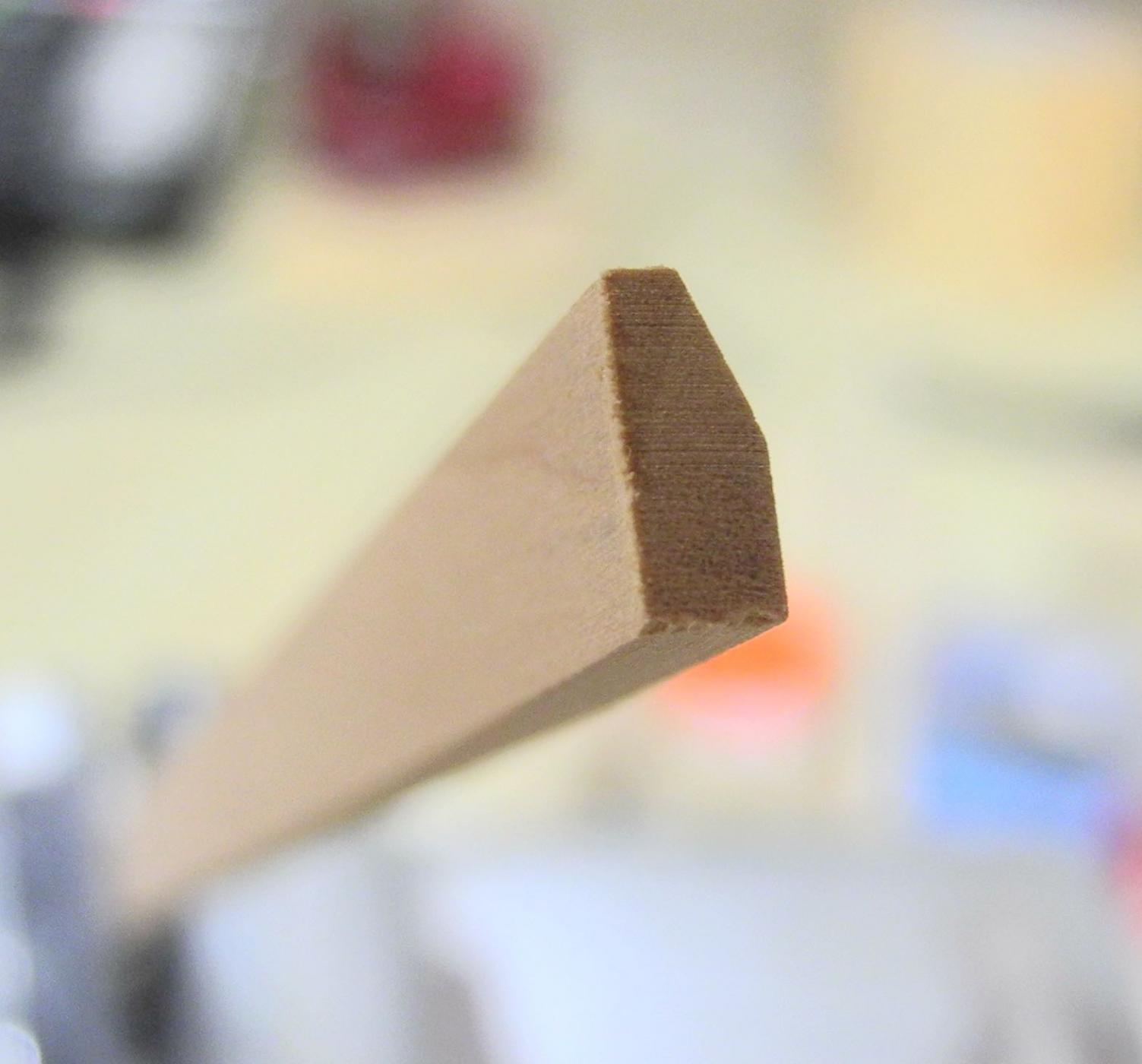
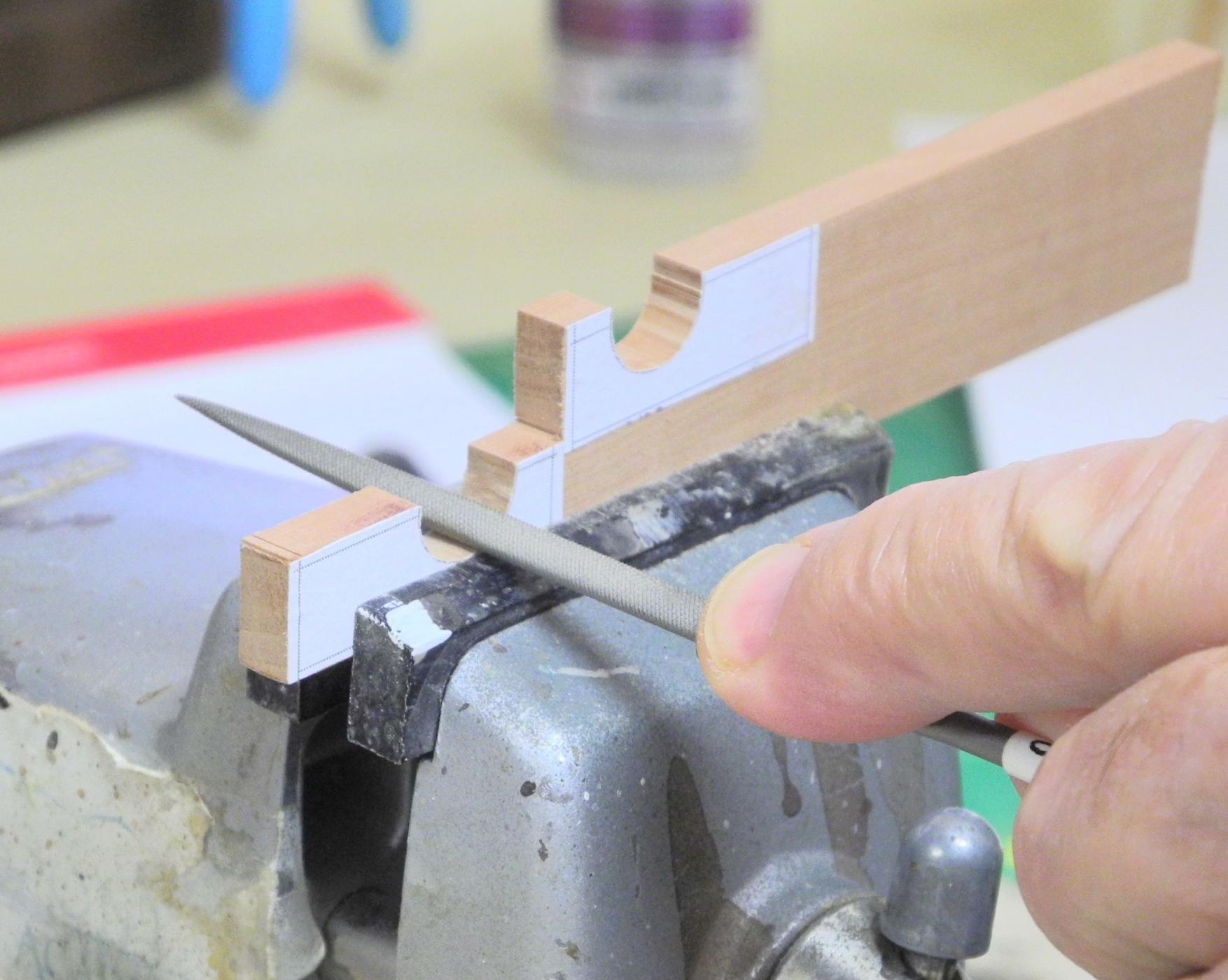
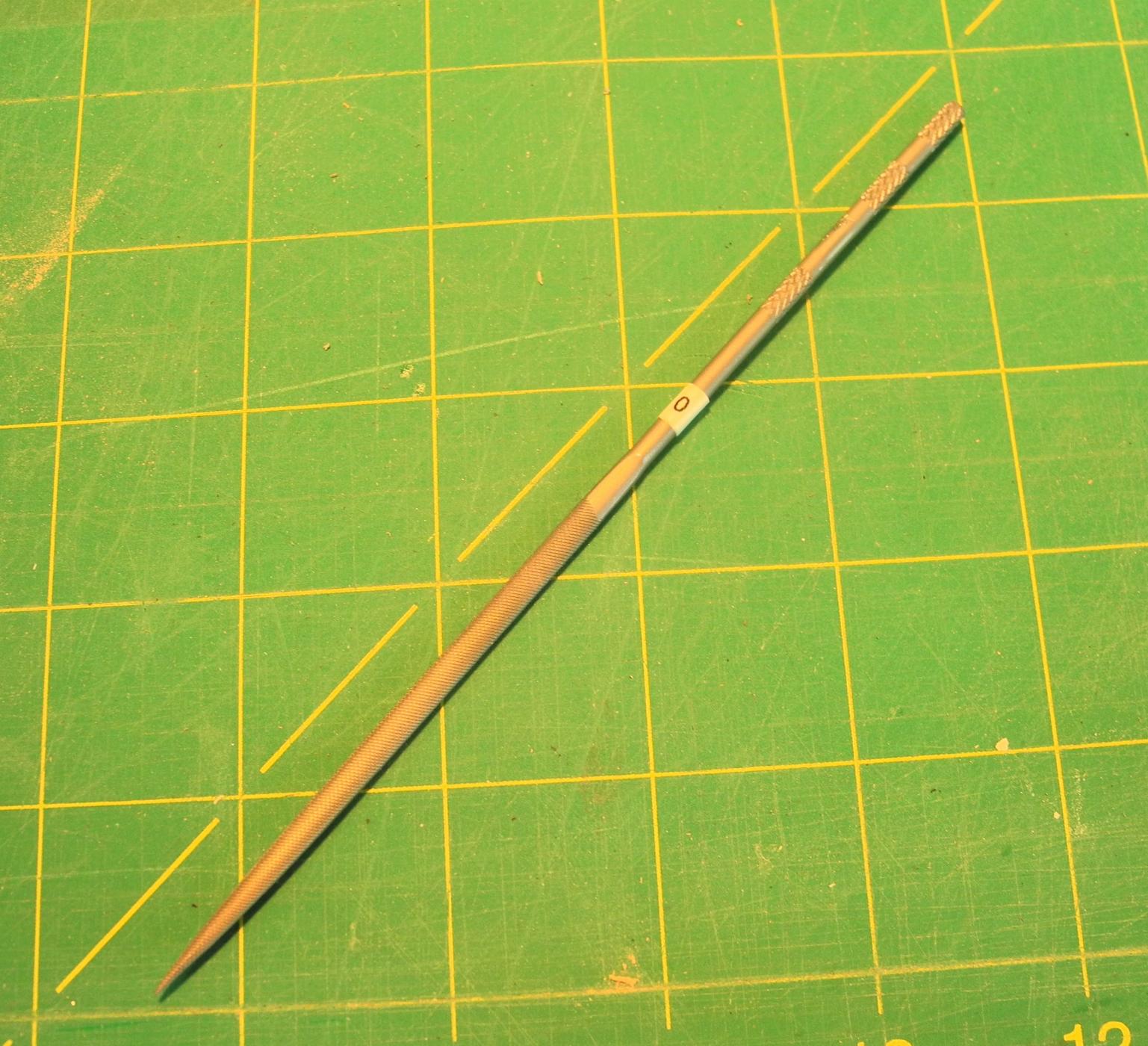
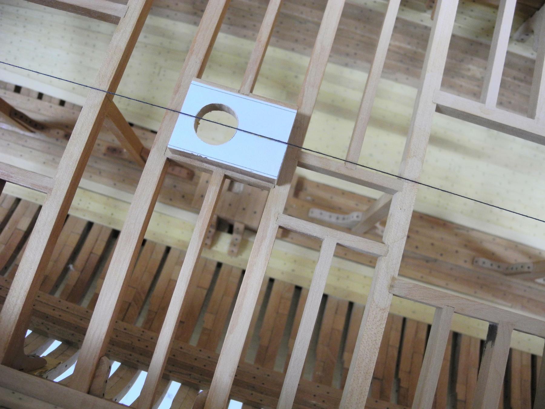
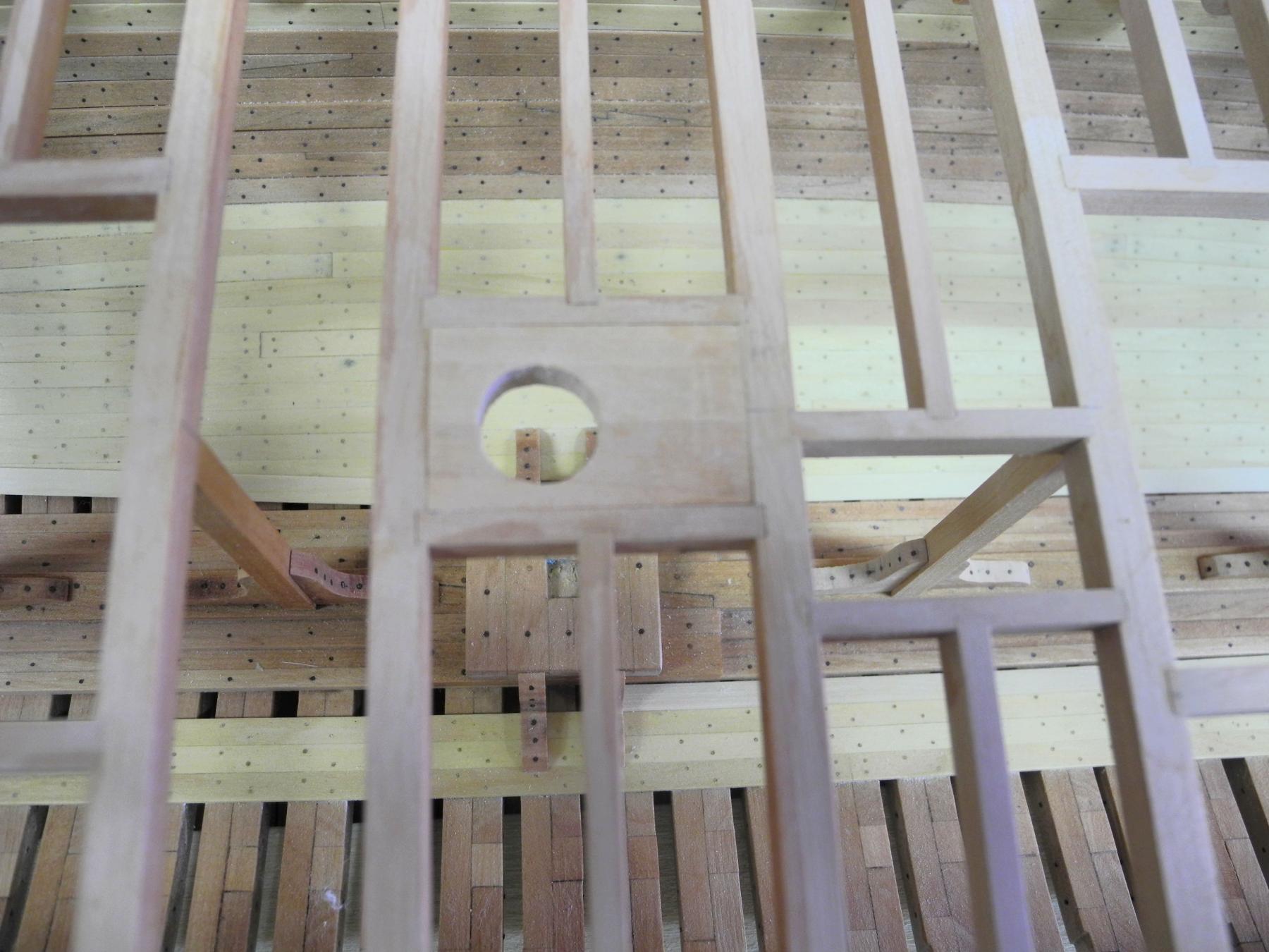
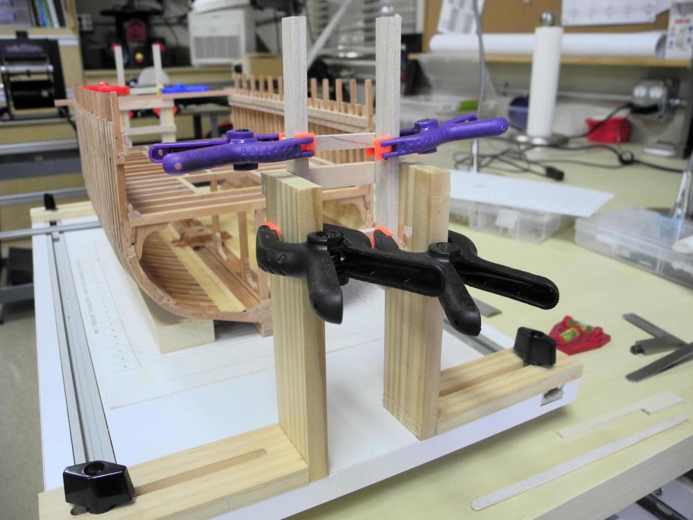
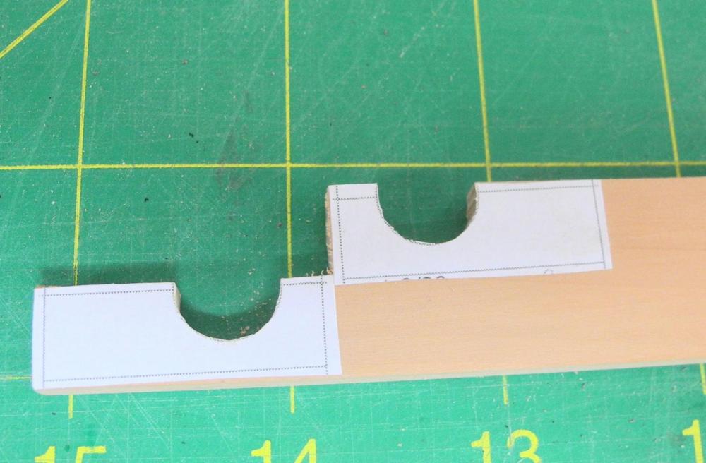
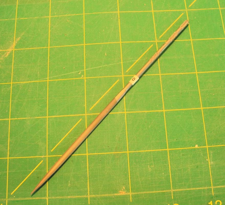
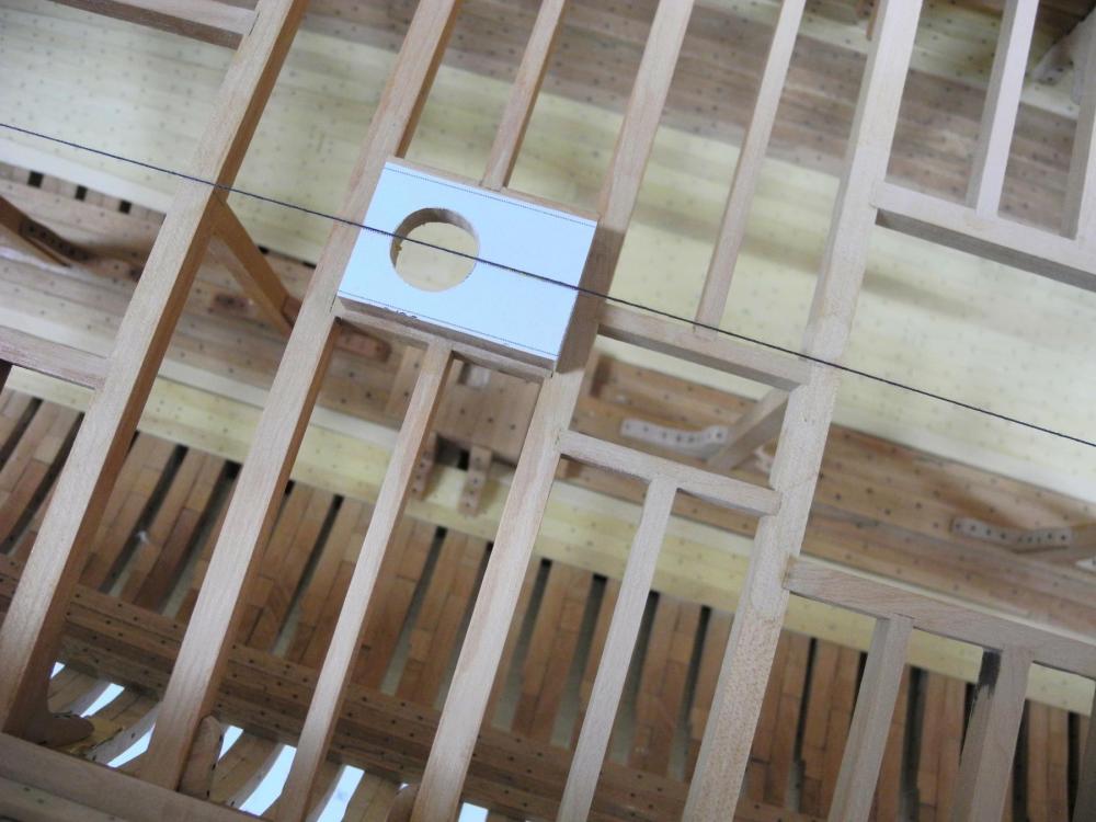
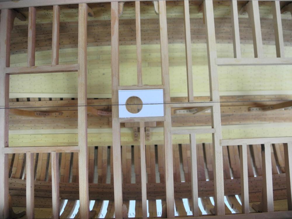
Part 28 – Margin Plank, Upper Clamp, and Mast Partners Since my last post I’ve worked on several odds and ends: Installed lodging knees for the beams holding the Mast Partners. These knees are mostly hidden by the Margin Strake, so I didn’t take any photos. Trimmed the partial bilge ceiling on frame #35 starboard side – these partial strakes were installed to give the knee a base Pinned the main beams at frames 19, 22, 41, and 44. I used 1/32 brass rods as functional bolts epoxied in place. This was done to prevent the forward and aft parts of the frame from spreading. Added a stanchion and knees to the beam for the main hatch at Frame #38 (this was omitted in error). Did some general cleanup and light sanding. I didn’t take any photos of the above work – not very interesting. Margin Plank and Upper Clamp for Accommodation Deck The Margin Plank and the Upper Deck Clamp on the Accommodation Deck both have a bevel, which needed to be milled. The Margin Plank bevel is too deep for any of my miniature router bits, so I had to use the tilting table to get the correct angle, as shown in the following photo. The following photo shows the profile of the Margin Plank The Margin Plank was soaked in boiling water and then clamped in place to dry. No simulated bolts were used, since the bolting pattern would be hidden by the Upper Clamp. The Margin Plank was then lightly sanded and installed. The bevel on the Upper Deck Clamp is very small, so I was able to use a mini router bit to cut the bevel, using the routing setup in the following photo. The plank was pushed into the router bit from the left, while a piece of scrap wood was used to keep the plank against the fence. Simulated bolts were then installed using the process covered in a previous post for other planking, and the clamp was then soaked in hot water and clamped to the hull for shaping. After the clamp was dry, it was lightly sanded, the bolts were blackened, and the clamp was installed. Mast Partners I made the mast partners as two pieces. The first step was to rough cut the mast opening on the scroll saw. The hole was then refined using a file The file I used is a Grobet oval needle file, cut 0. The oval shape gives me good control on a concave part. The opening for the mast partners was slightly off center, so I needed to cut the overall shape to match where the opening should be. The first step in aligning the partners was to orient the hole on center and mark the edges to be cut. The partners were test fit to make sure the hole was still centered. As a visual check I wanted to check the alignment of the mast with the partners. I clamped straight rulers so that they were perfectly vertical with one edge on the centerline, and visually checked that the center of the mast was aligned with the rulers’ edges. Using two straight edges fore and aft of the mast eliminated parallax in viewing the mast alignment. Finally, the mast partners were installed. Thanks again everyone for following and for the ‘Likes’ and comments – the encouragement you give me helps to keep me motivated!


- 649 replies
-
- 19
-
-
- dunbrody
- famine ship
- (and 2 more)
-
Rob - I'm looking forward to following your build.
- 1,208 replies
-
- 1
-
-
- great republic
- clipper
- (and 1 more)
-
Thanks Druxey (it's Frank, not Albert ). I'm glad I won't need to pull out the alcohol once again!
- 649 replies
-
- 5
-
-
- dunbrody
- famine ship
- (and 2 more)
-
Thanks Ed. Since Dunbrody was built in Canada there was probably a mix of Amercian and English building techniques used in her construction. I'm going to leave them as is.
- 649 replies
-
- 6
-
-
- dunbrody
- famine ship
- (and 2 more)