Mahuna
-
Posts
1,504 -
Joined
-
Last visited
Content Type
Profiles
Forums
Gallery
Events
Everything posted by Mahuna
-
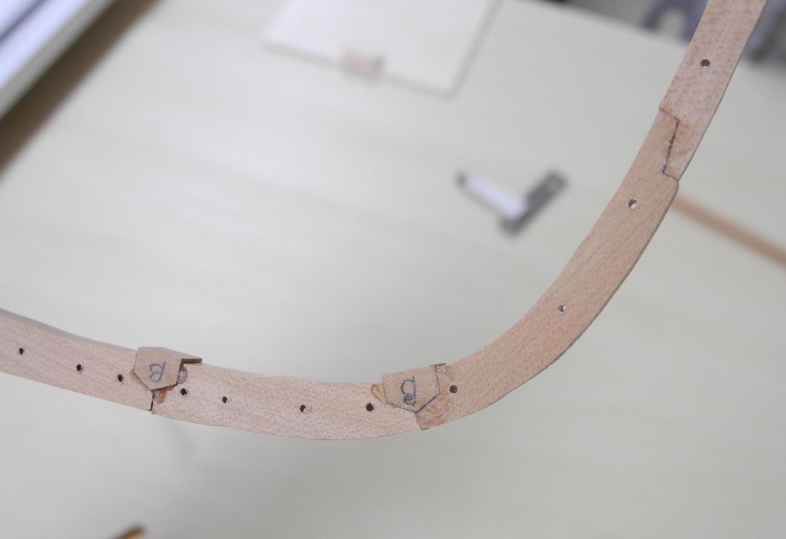
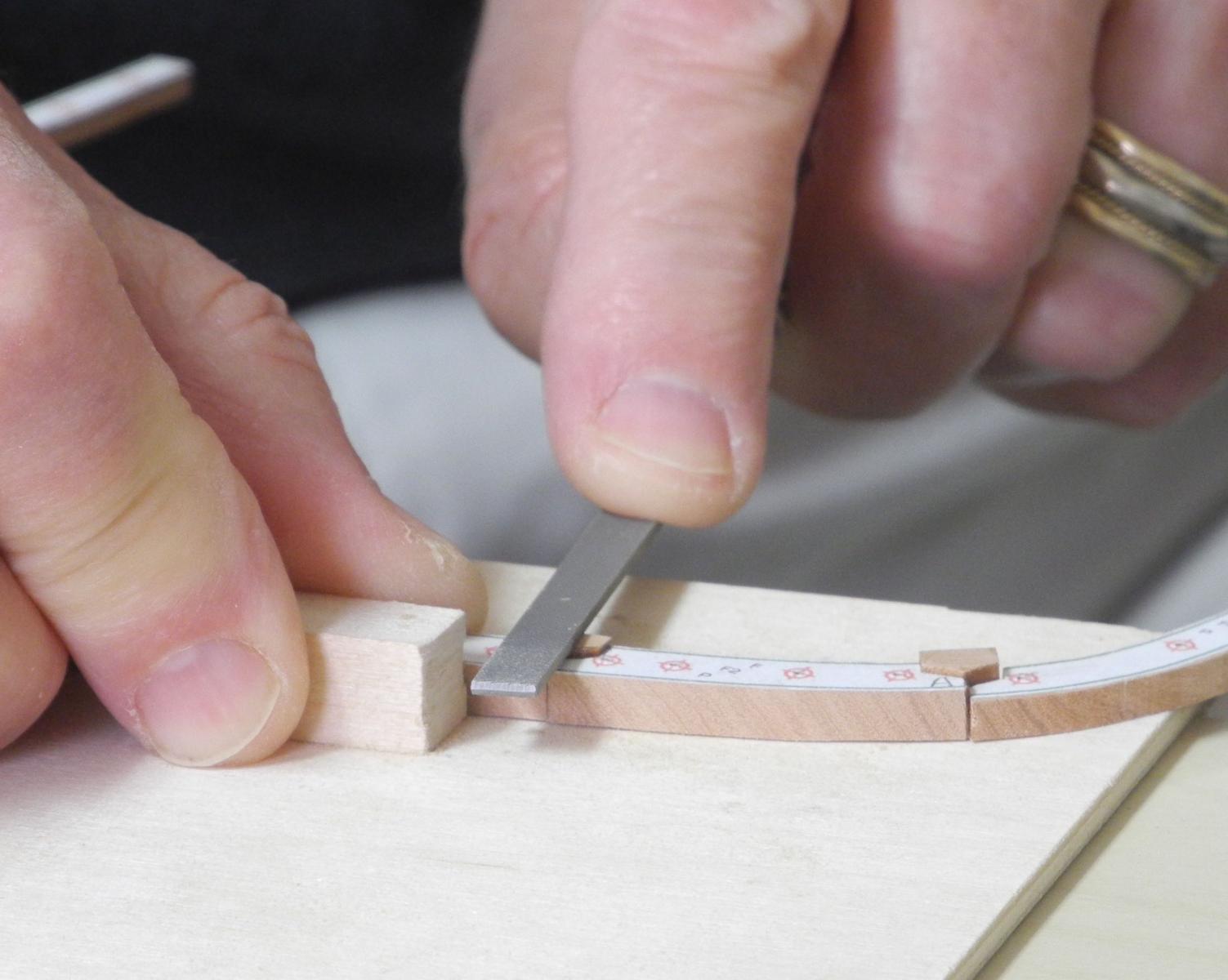
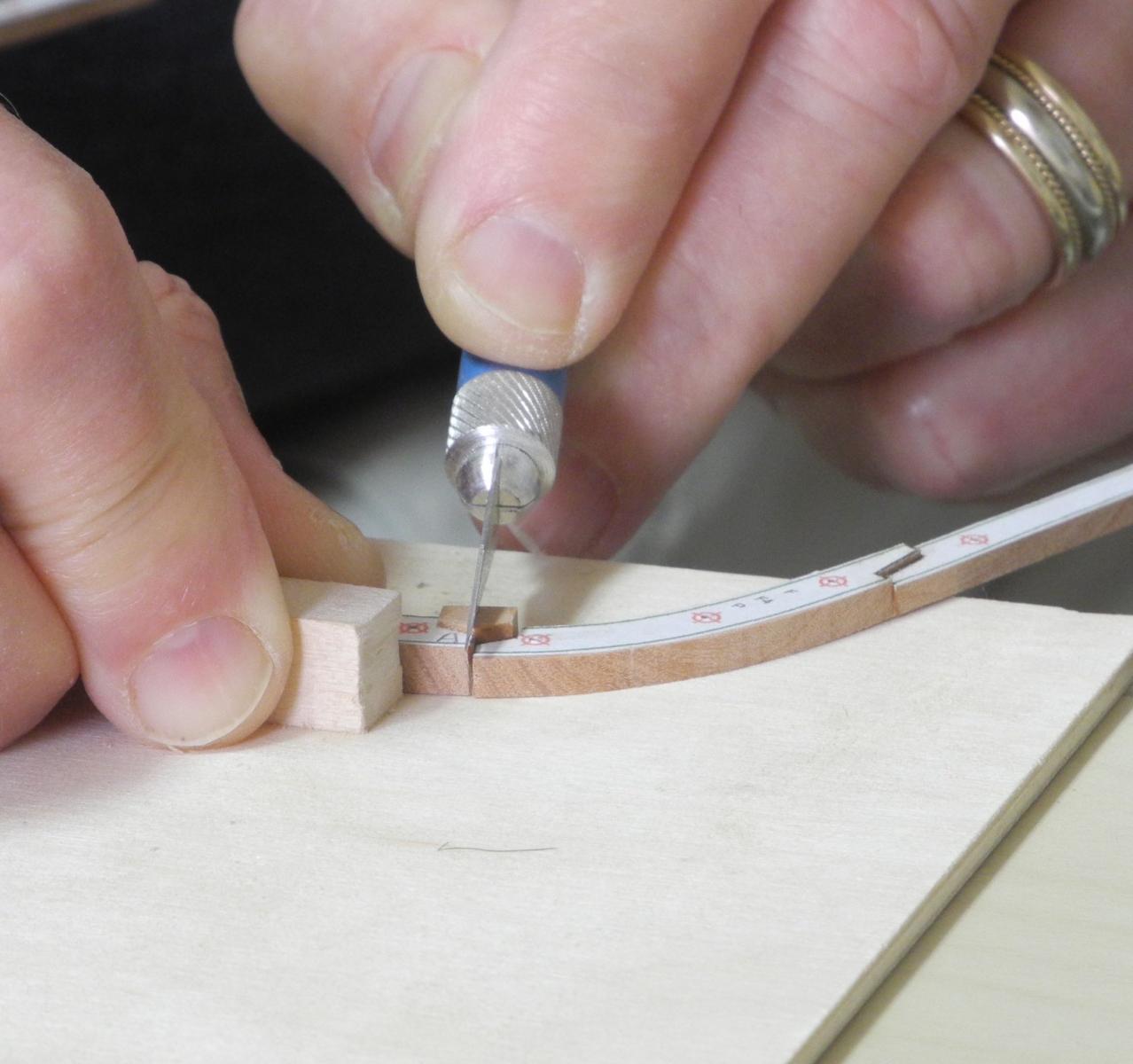
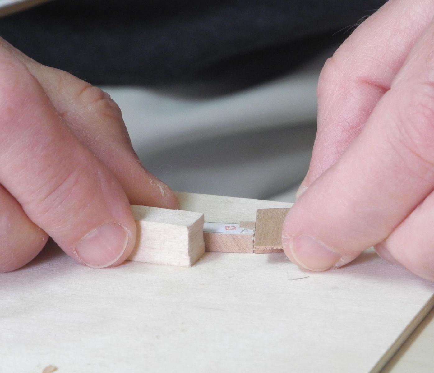
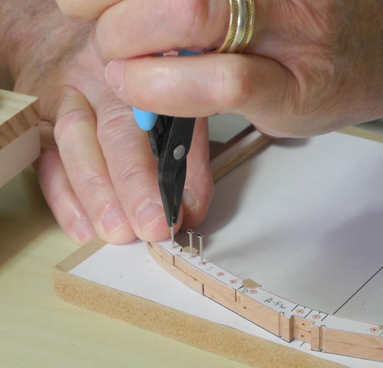
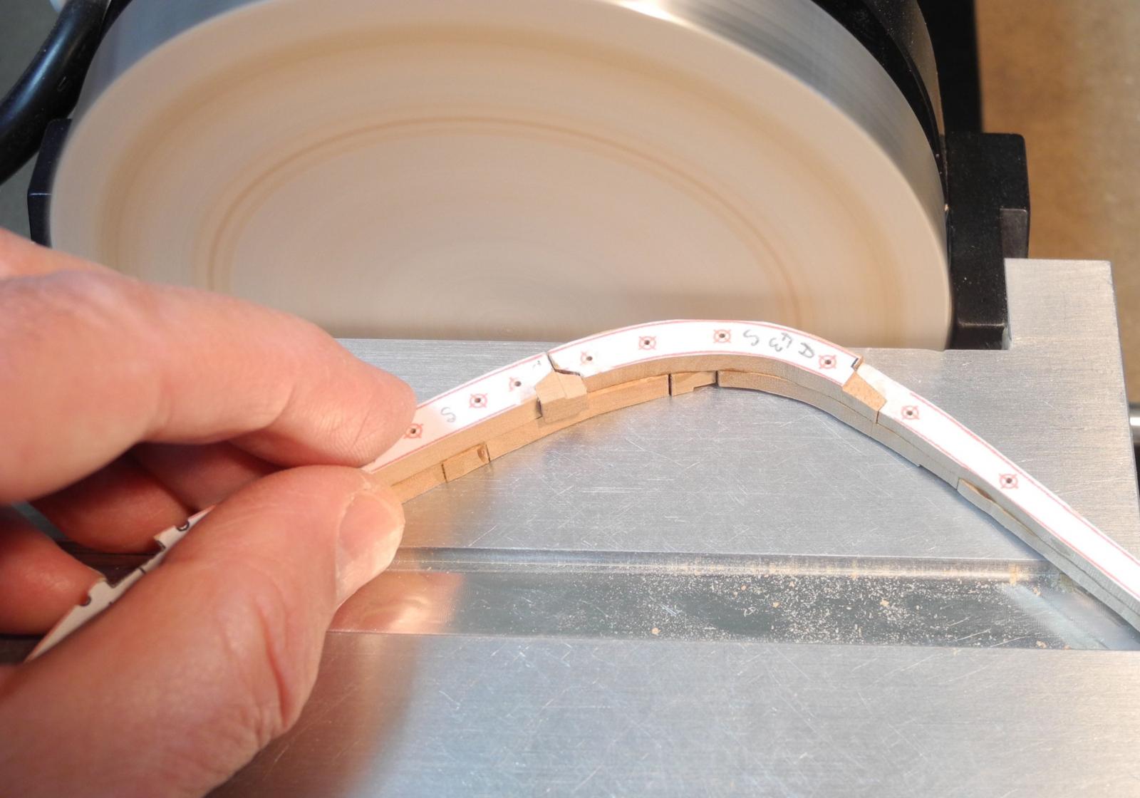
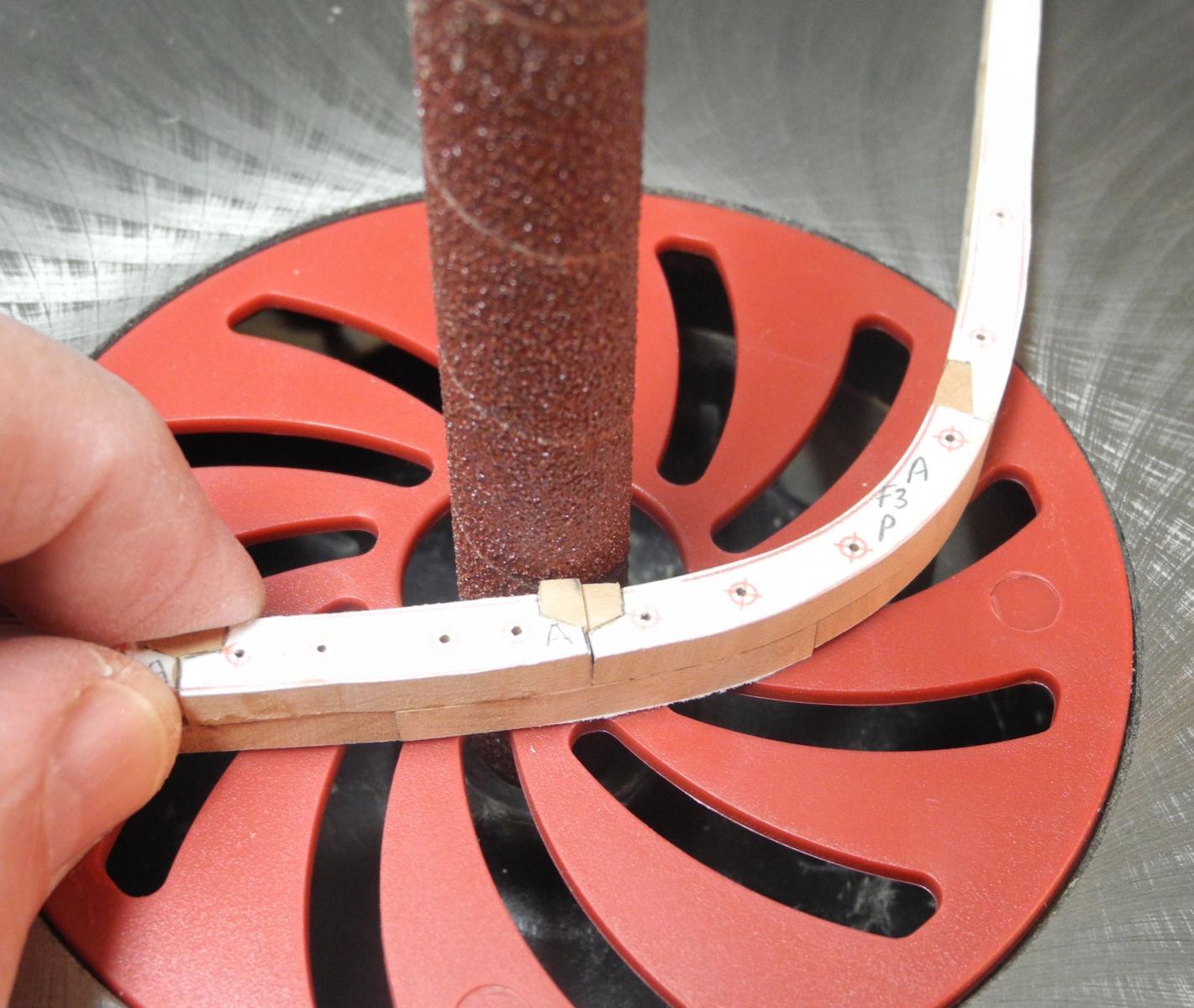
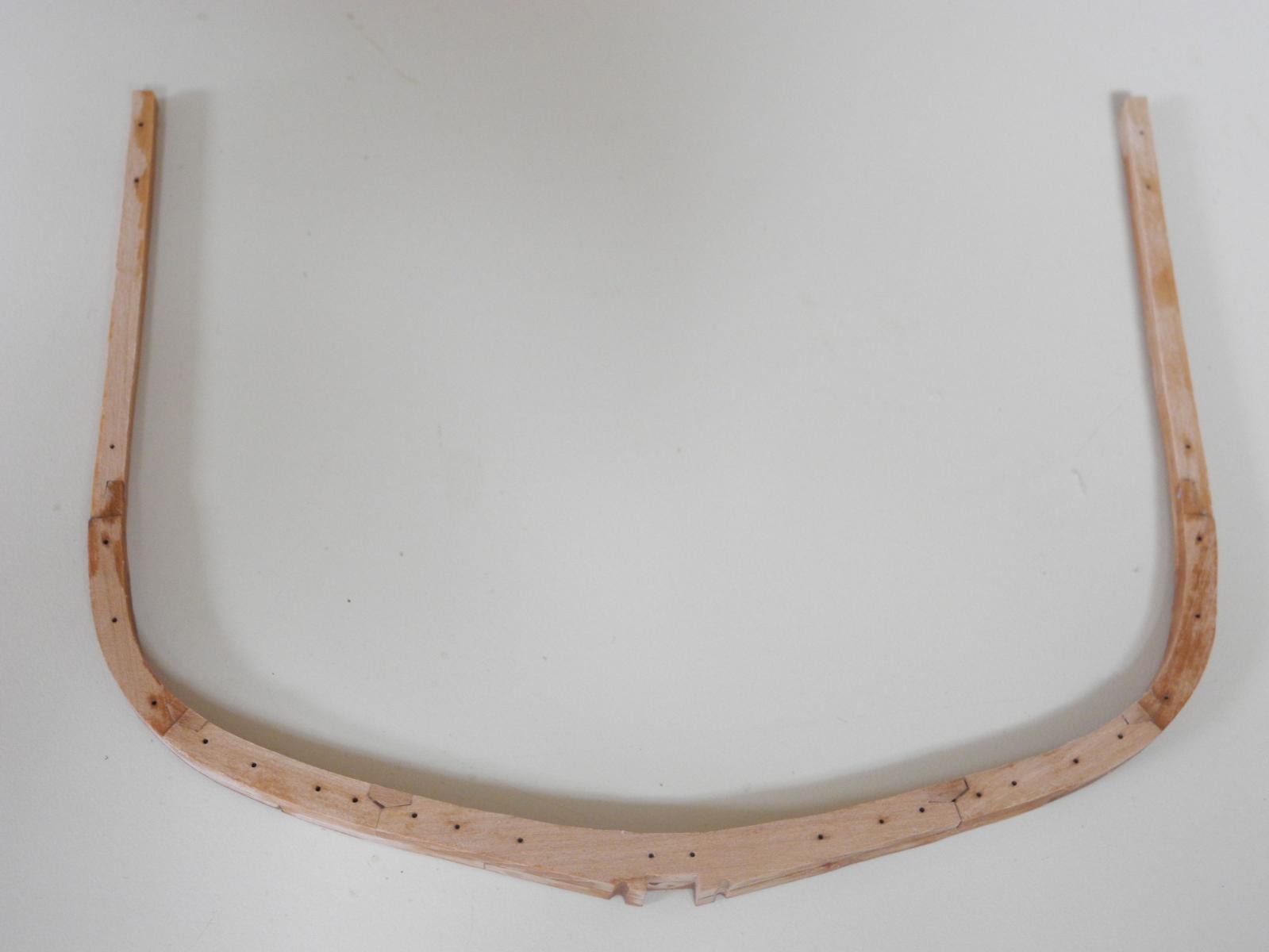
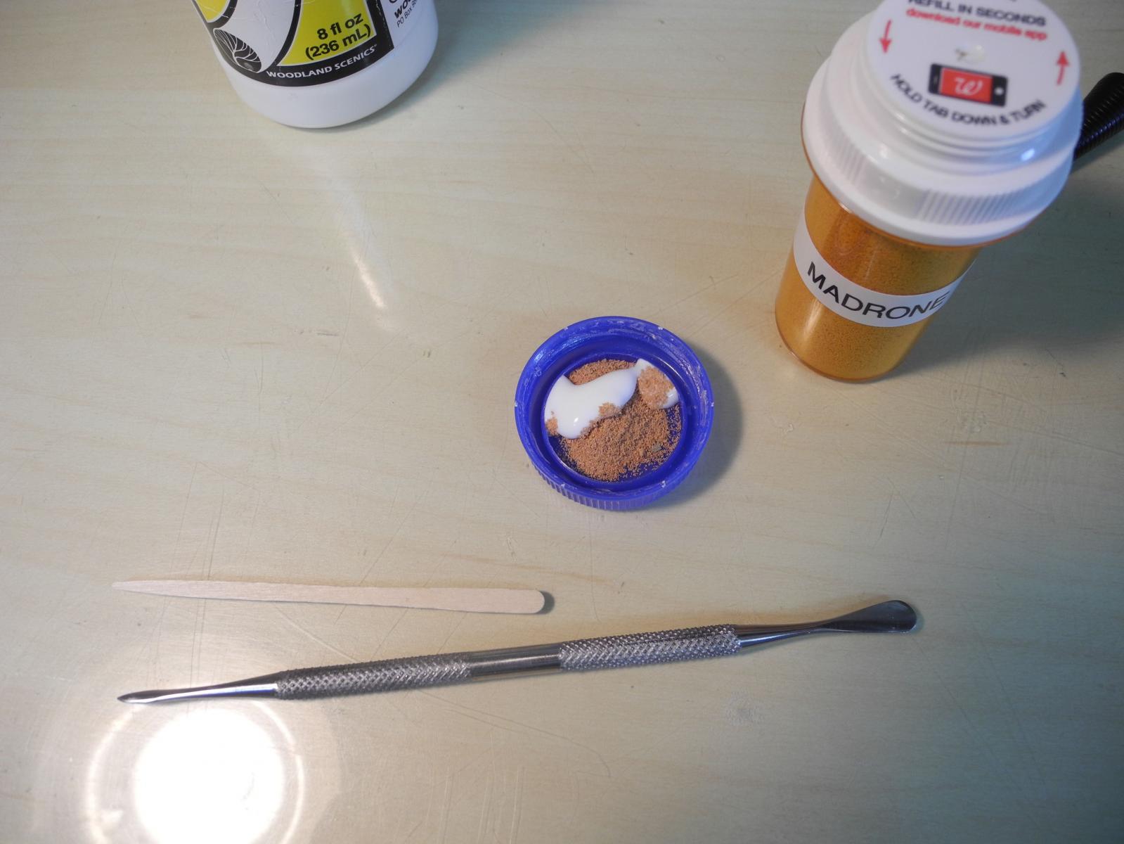
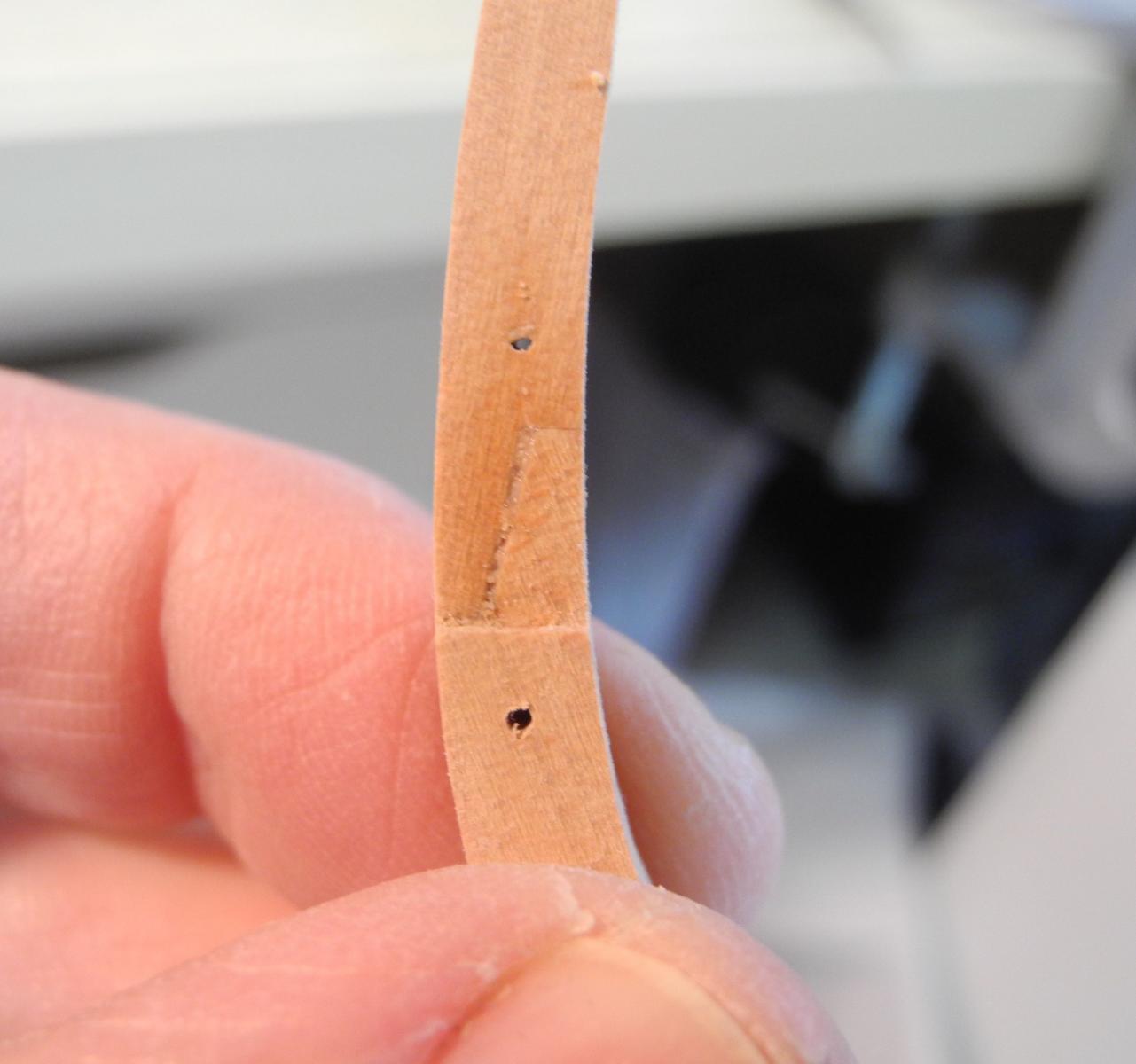
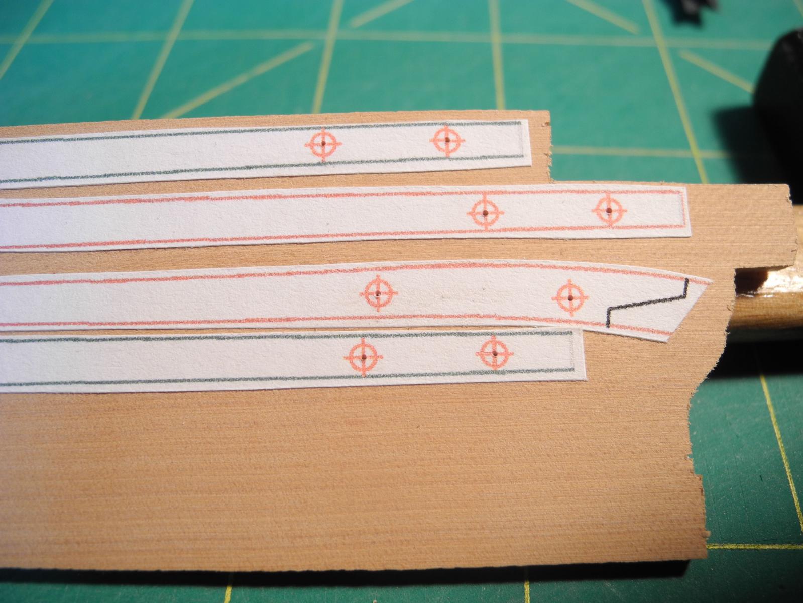
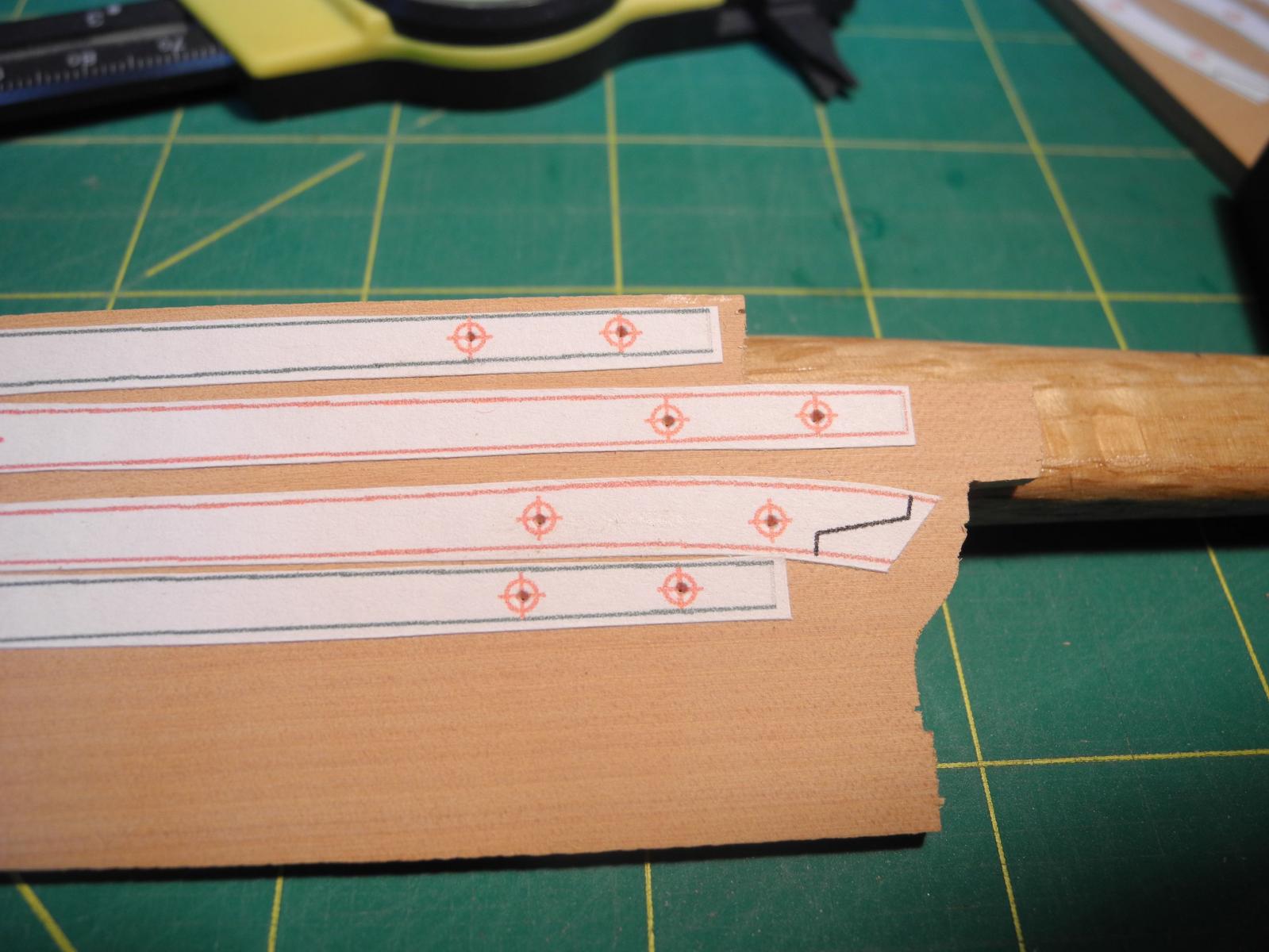
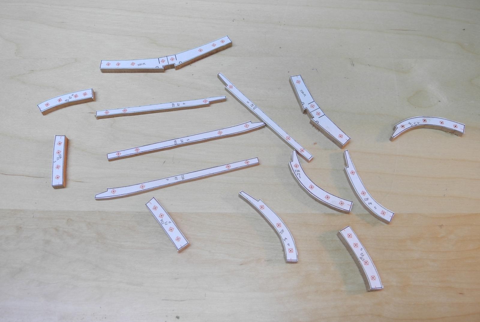
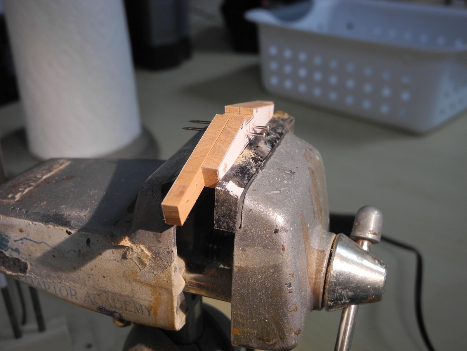
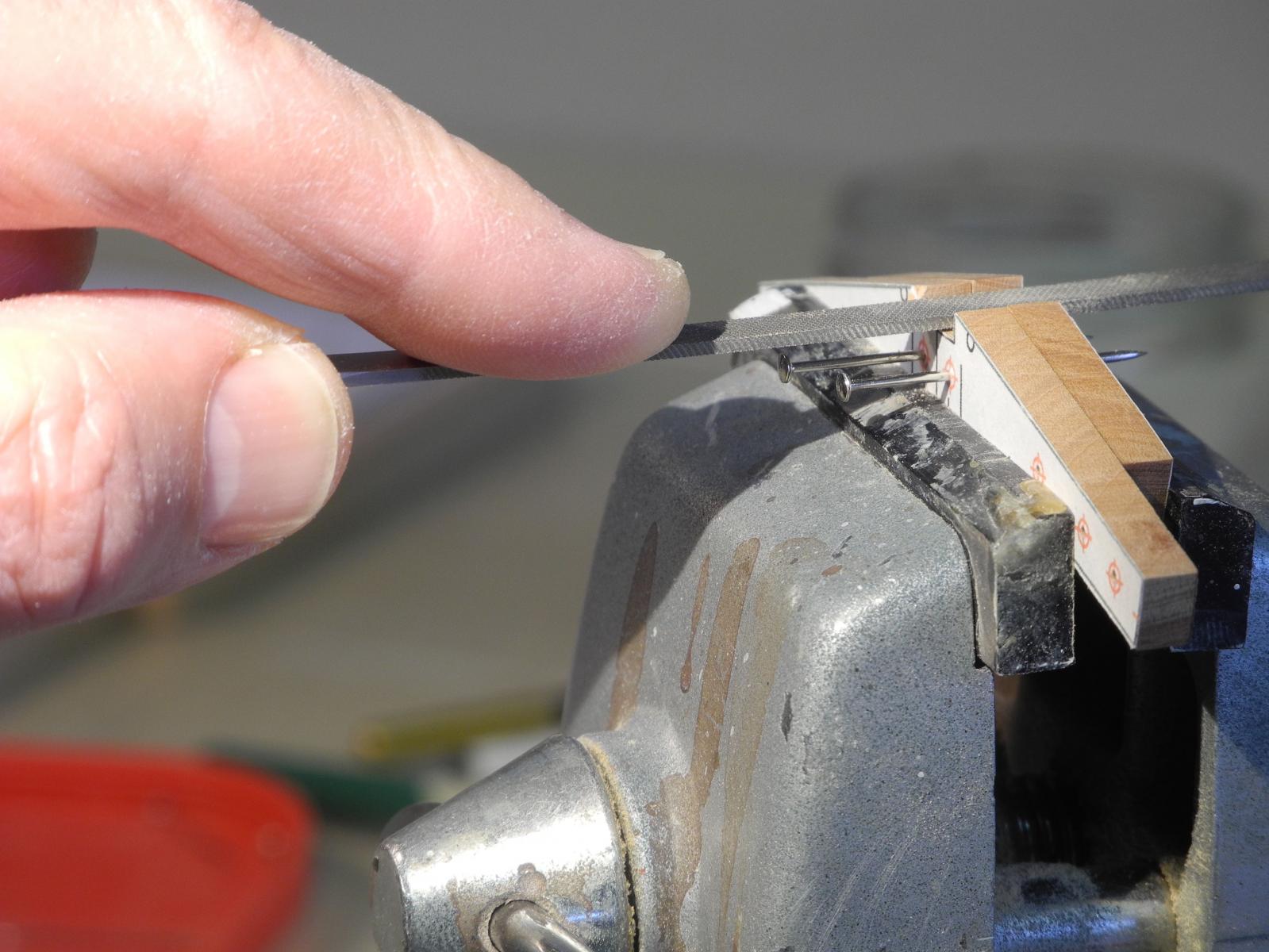
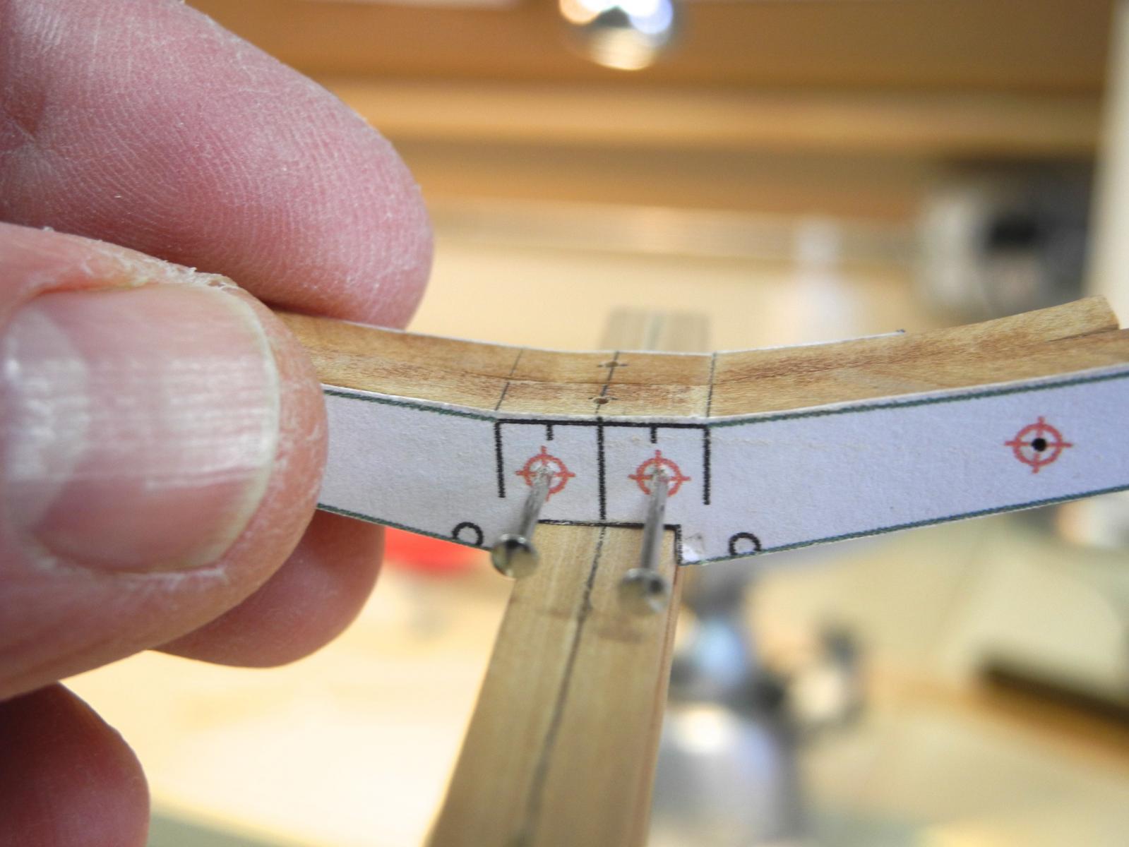
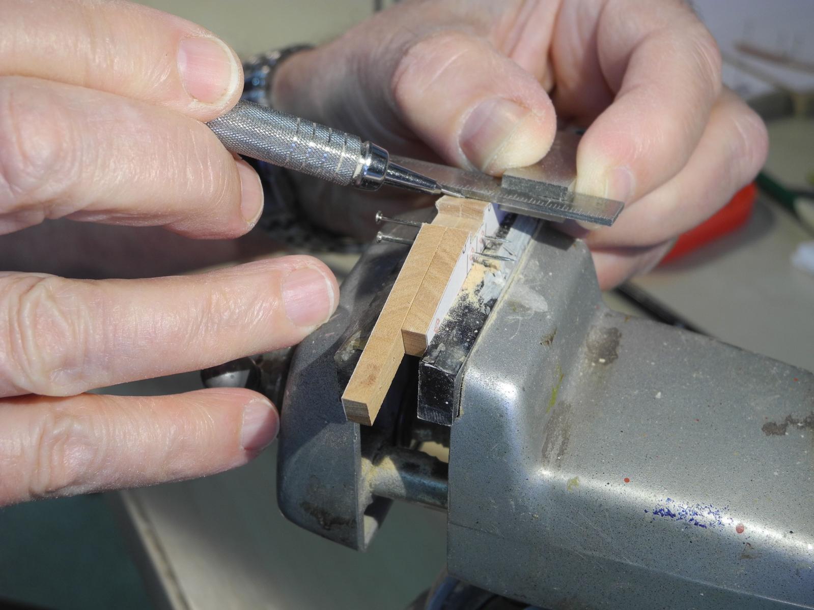
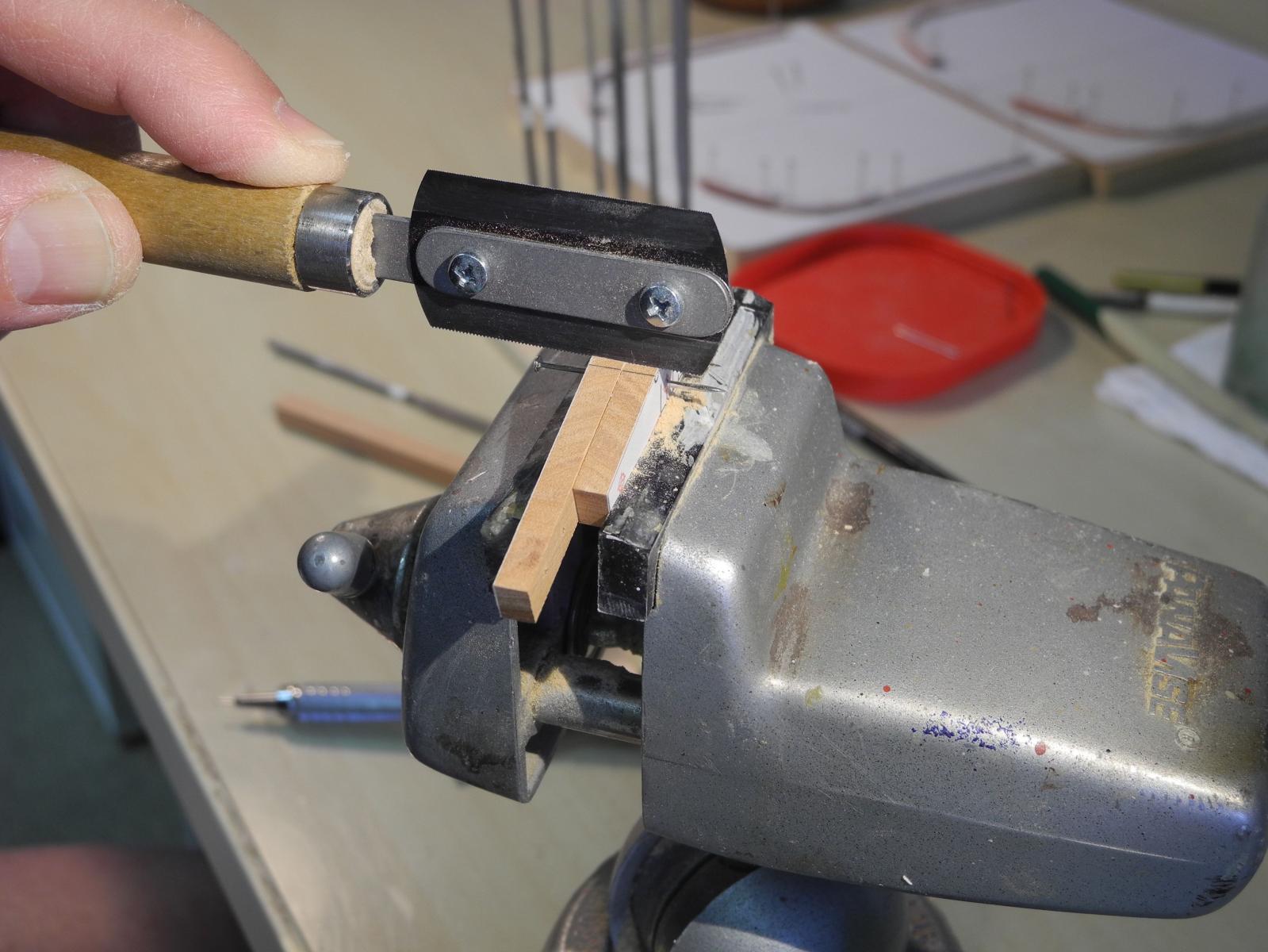
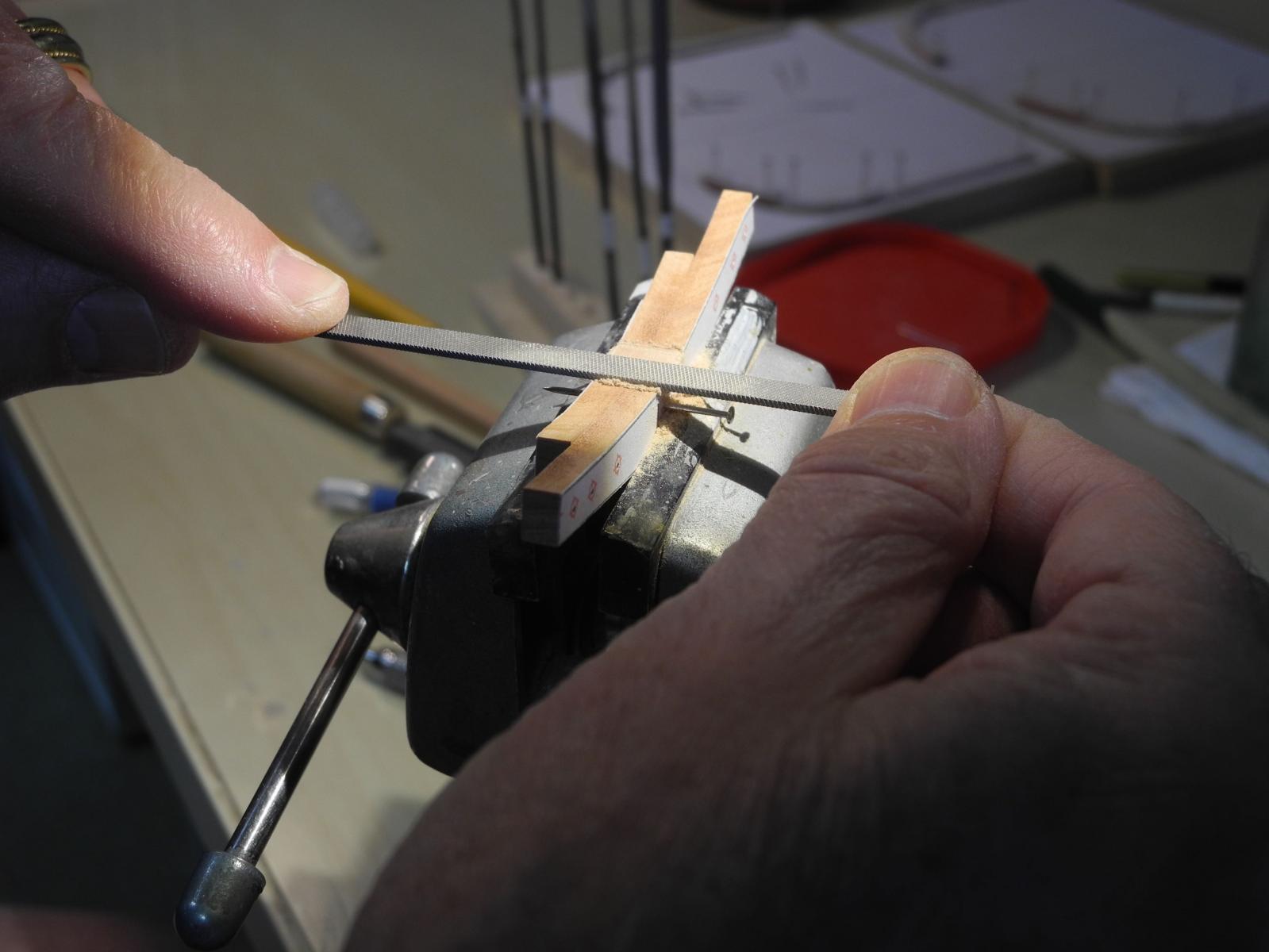
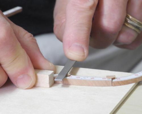
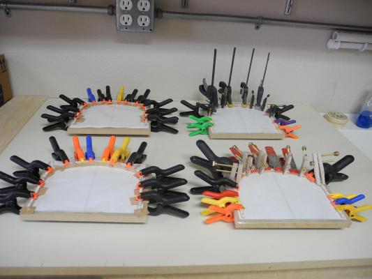
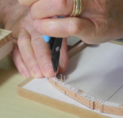
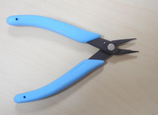
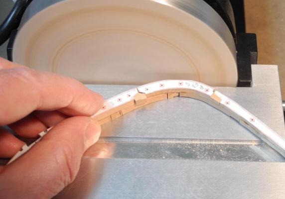
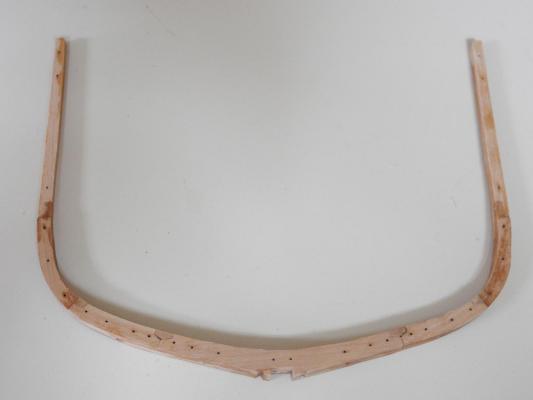
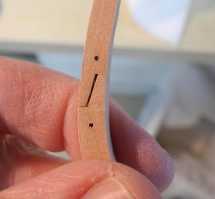
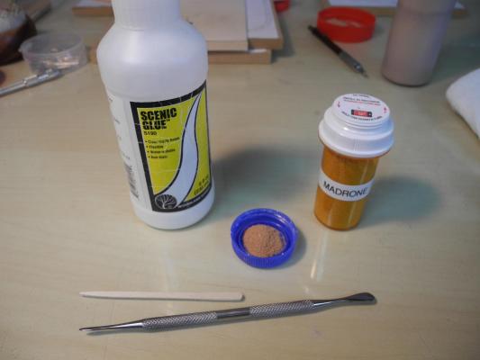
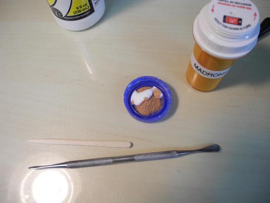
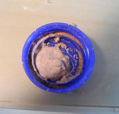
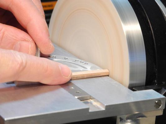
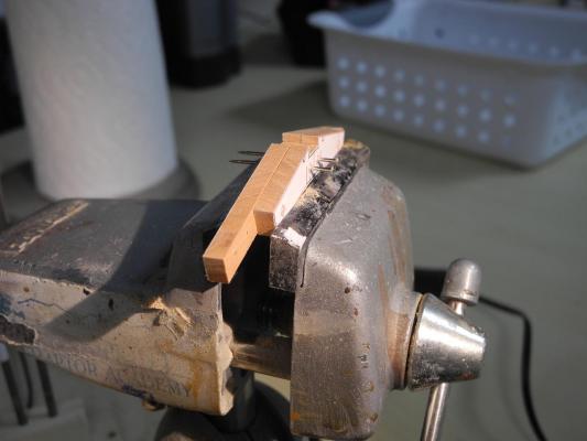
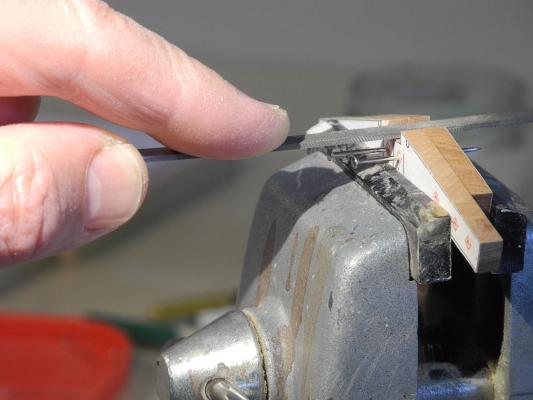
 Part 8 – Frame Construction cont’d Phase 3 – Assembling the fore and aft frames and joining them for the frameset. The glued and clamped single frames have been left to dry overnight. After drying, the frames are unclamped and unpinned. The single frame is thin and has several delicate joints – the chocks and scarfs – and needs to be handled carefully. It’s important that the back side of the frame is clean and flat so that it properly mates with the sister frame. There is typically some glue residue on the back side, and some joints may not be perfectly flat. Some sanding, filing, and other cleanup still needs to be done while the frames are still single, so I use a fixture for holding them securely while working on them. The back is cleaned up using a sanding stick with 180 and 220 grit paper attached. This is typically enough to clean the back. The chocks are oversized in depth and height when they are installed, to ensure a good fit. Because of the way the chock was installed, the extra depth is on the front side. This is removed by filing, first with a coarse file and then with medium. To check that the chock is flush with the face of the frame, I lightly drag the side of the file from the face to the chock. If I feel a step then more filing is needed. The moulded dimension of the futtocks decreases by 1/32 inch between the first and third futtocks on the aft frame (or second and fourth on the forward frame). Consequently the chocks that are located between futtocks need to reflect this step down so that one side of the futtocks is 1/32 greater than the other side. A stop cut is made down the middle of the chock, and some waste is pared away to make a slight ledge in the chock. The step is then filed down to be flush with the smaller side, and the higher side is than also filed down. The depth of the step is checked using a scrap piece of 1/32” lumber. The chocks should then appear to be blended into the timbers. A similar reduction in moulded dimension occurs at the scarf, so a similar step is made there. The difference is that the entire scarf joint becomes the smaller size. After both fore and aft frames have been cleaned up and the joints properly shaped, the frames are ready to be joined as a frameset, or sistered. The two frames are pinned together on the Pinning Template, leaving a space between the frames for applying glue. The pattern is facing out for each frame. Pieces of scrap 1/32” lumber are placed under the upper part of the bottom frame – 2 pieces under the Rising Timber or Top Timber to support the 1/16 space, and 1 piece under the third futtocks to provide support for the 1/32” space. Glue is then applied to both inside surfaces and the frameset is then clamped and left to dry overnight. As far as clamps go, I feel you just can’t have too many. I almost ran out of clamps today because I had several frames in process simultaneously. After the frameset has dried overnight it is removed from the Pinning Template. I found that the glue makes it difficult to remove the pins by hand, so I use a Xuron pin insertion plier, which has a hooked end that will grab the pinhead. (I also found that I’d better scrape the dried glue off the pin if I want to re-use it). Using the disk sander, the outside curves of the frameset are then sanded down to the printed line. The height of the chocks is still oversized, and this will make sanding the interior lines difficult, so I use a very small sanding drum on the spindle sander to reduce the chocks. The inside curves are then sanded to the lines using a medium sanding drum. Note that I’ve replaced the base plate for this drum with a homemade version. The base plates for this sander (an inexpensive model) are not flat and are thinner than the slot they fit in, making it difficult to sand the frames properly. The drawing can now be removed from both faces of the frameset. This is done by wetting the paper and then removing it by scraping with a razor blade. There will still be a glue residue on the wood, so I wet it and scrape it again. This leaves the frameset fairly damp, so it needs to be left to dry. Typically, there are one or more places on the frameset where the joints are not as tight as they could be, as in the following photo of a scarf joint. To make this less obvious I use a filler made from sawdust of the wood in use. The sawdust is mixed with Scenic Glue, which is a PVA glue that dries completely flat. The filler is pressed into the bad joint until the joint appears to be completely filled. Any excess filler is scraped off while still wet, and the joint is rubbed down with a paper towel. After drying, the joint can be sanded. Construction of the frame is completed, but there is still more preparatory work that needs to be done before the frame can be erected on the keel. I’ll cover this in a future post. Thanks everyone for following!
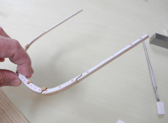


- 649 replies
-
- 19
-

-
- dunbrody
- famine ship
- (and 2 more)
-
Thanks Glenn, but it can't compare to your craftsmanship.
- 649 replies
-
- 4
-
-
- dunbrody
- famine ship
- (and 2 more)
-
Hi Bob I wish so, too - you'd be a great addition to our little group. Good news is that I think Dunbrody will travel well, so next time I visit I'll bring her along.
- 649 replies
-
- 5
-
-
- dunbrody
- famine ship
- (and 2 more)
-
Yes Mark, there are to many other projects I want to do so a section will satisfy my needs on this one. Hi Rich - looks like our next meeting will be at my place so you'll be able to see it up close. Thanks Ed. I'm actually just trying to emulate your work. You're right about the chocks - at the model scale the frames are very delicate until they're joined to a sister frame. The next post will show the care needed to finish the frameset.
- 649 replies
-
- 6
-
-
- dunbrody
- famine ship
- (and 2 more)
-
Wonderful work, Druxey. It gives us something to aspire to.
- 641 replies
-
- 2
-
-
- greenwich hospital
- barge
- (and 1 more)
-
Your work is outstanding, Glenn, a pleasure to look at. Wish I could see it in person (maybe the next NRG Conference in San Diego??)
-
Thanks Patrick - liquid refreshment is always good at the end of the day (but first I make sure the shop is locked so I won't be tempted to run machines after a sip or two!) Fiddly yes, but also a learning experience.
- 649 replies
-
- 5
-
-
- dunbrody
- famine ship
- (and 2 more)
-
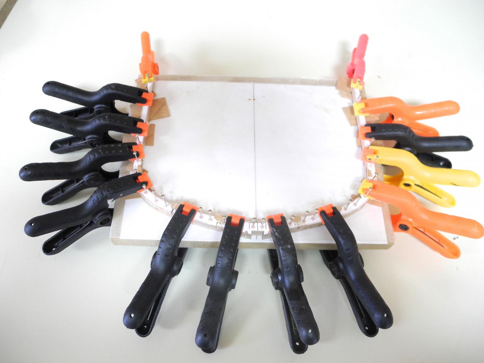
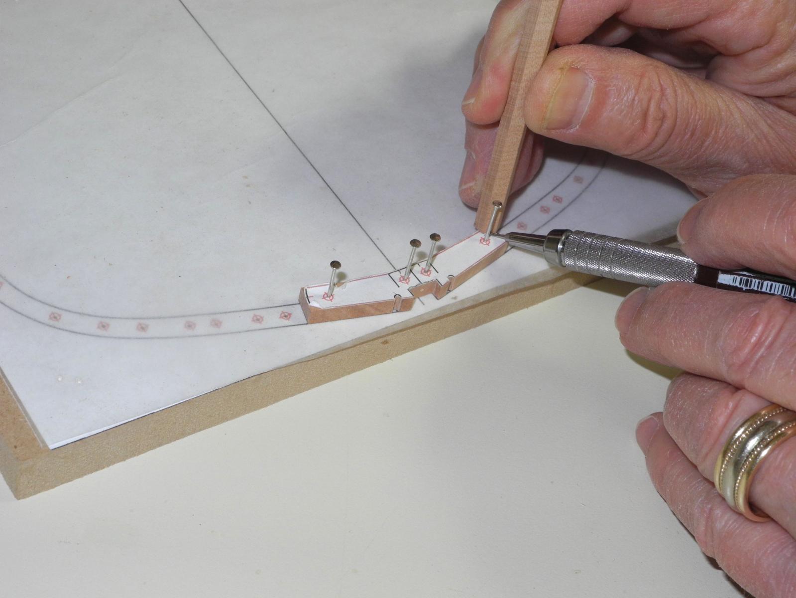
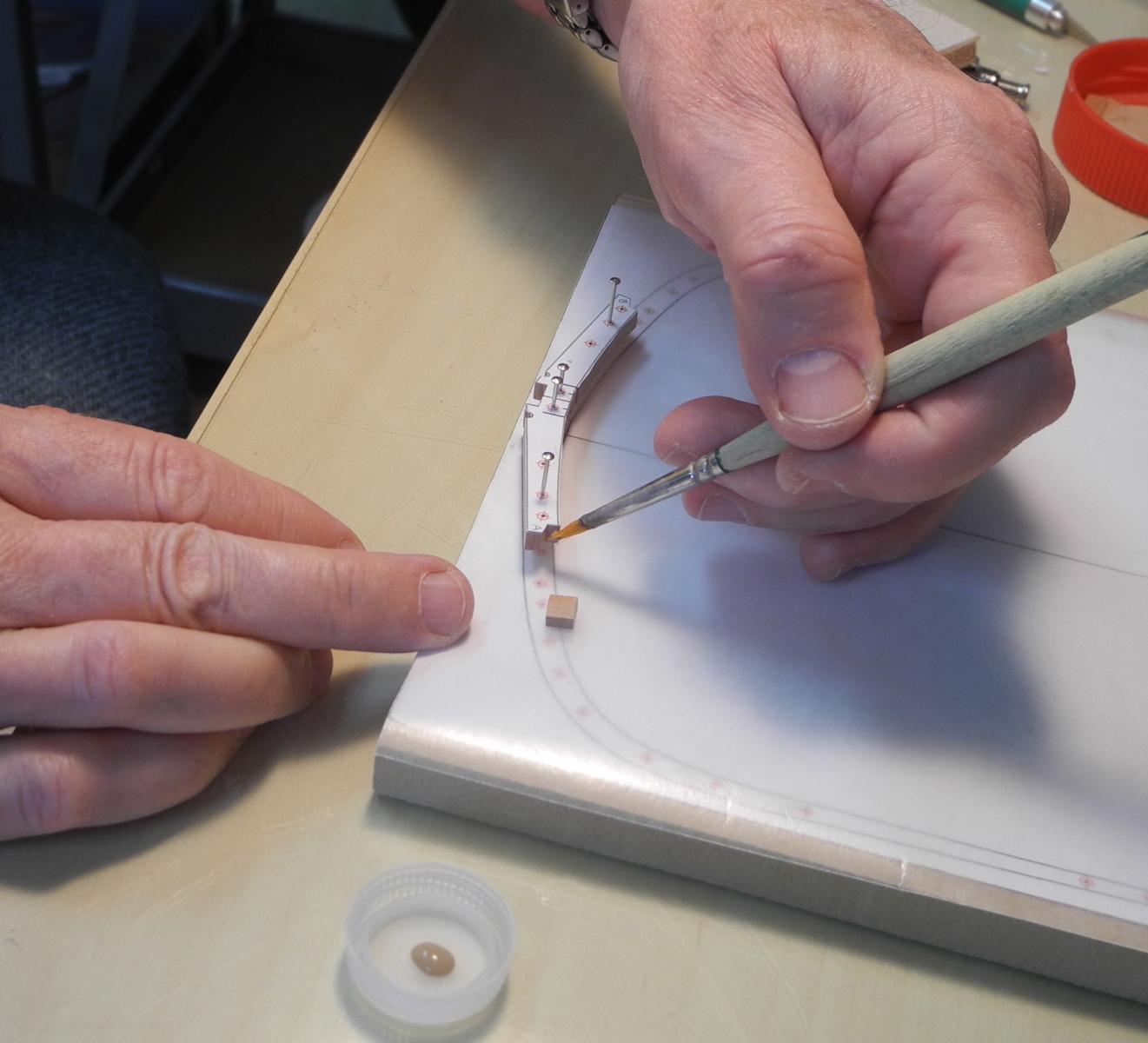
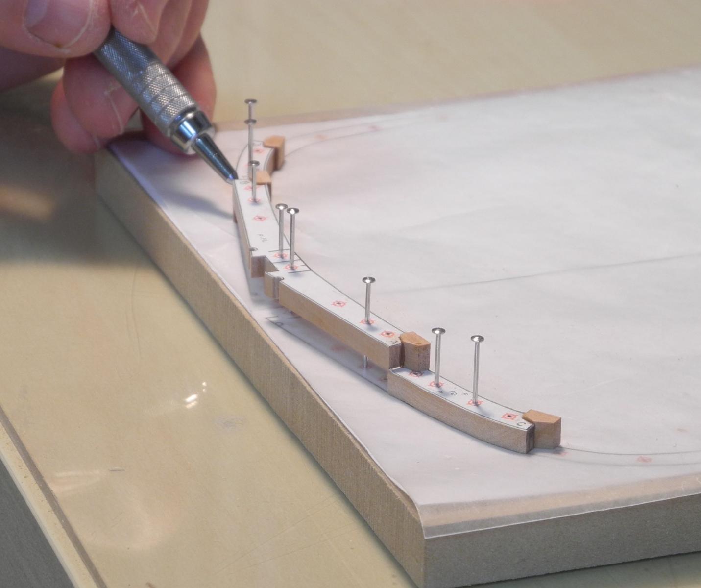
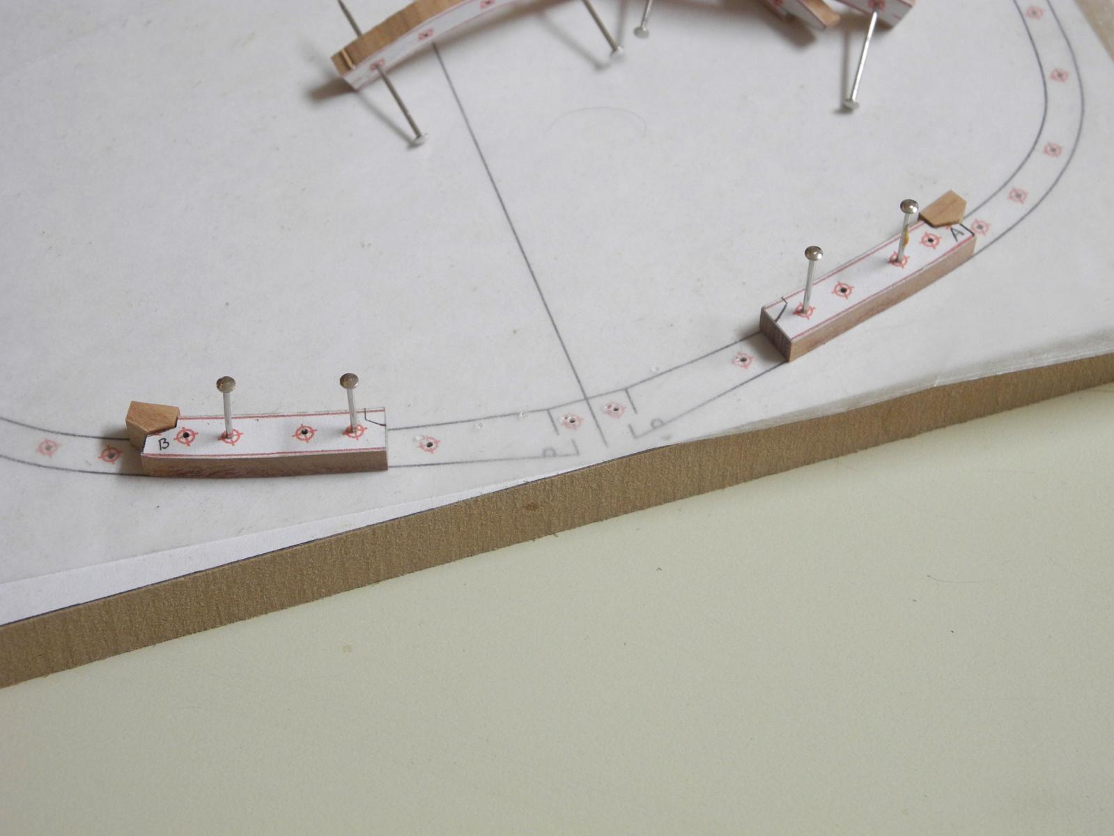
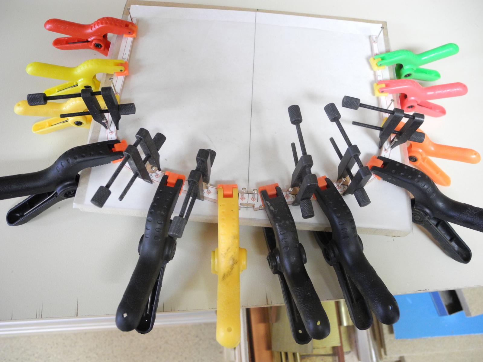
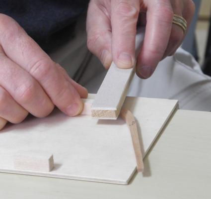
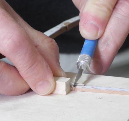
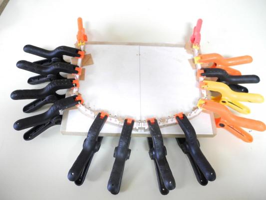
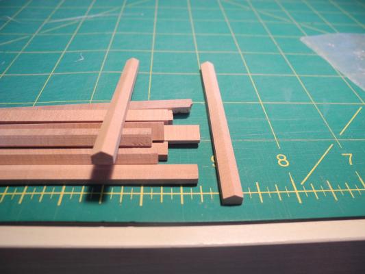
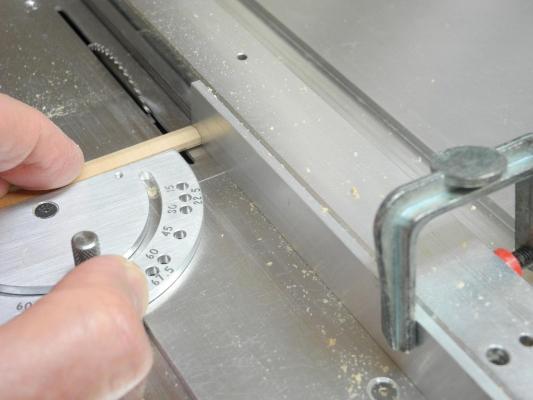
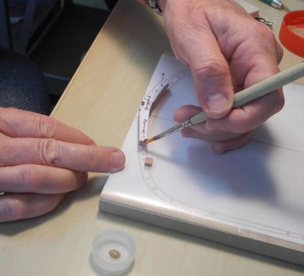
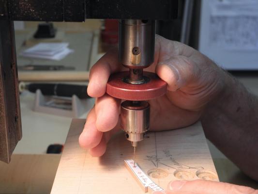
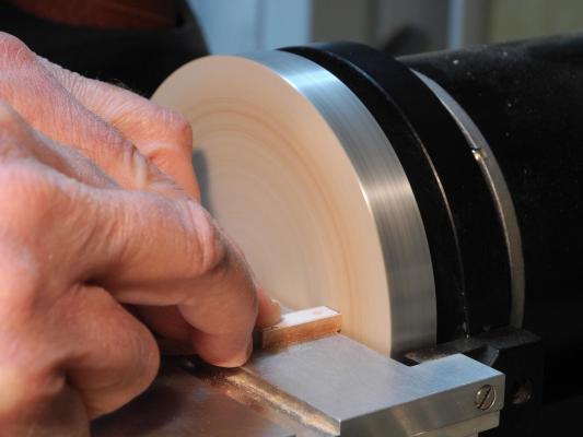
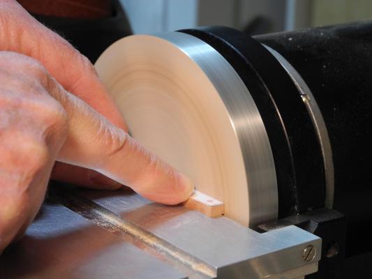
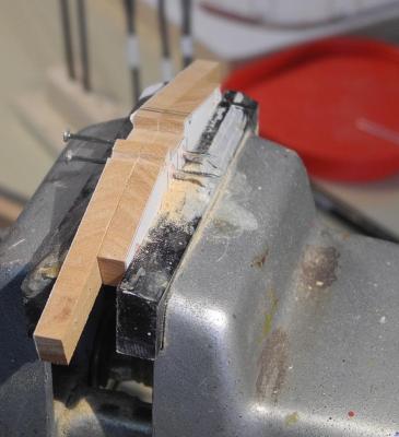
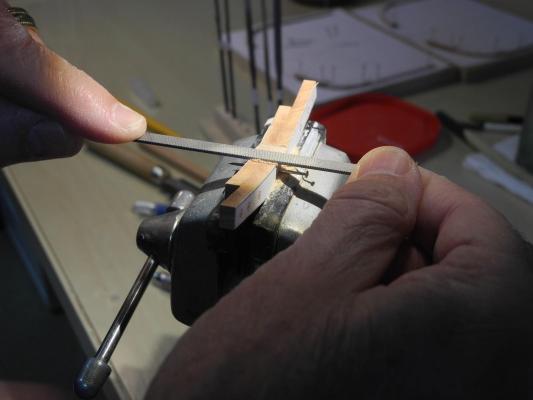
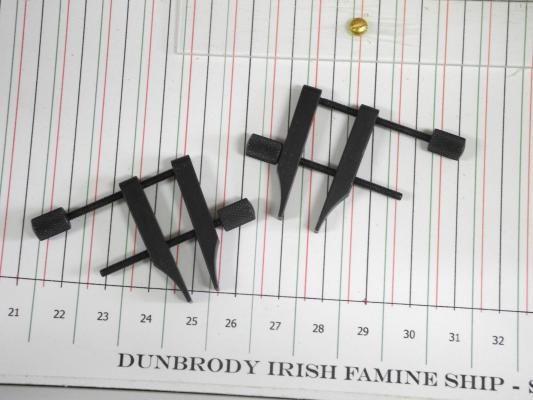
Part 7 – Frame Construction cont’d Phase 2 – Adding the chocks to the fore and aft frames. The frame chocks for Dunbrody measure 12 inches across. Compared to a ship like Naiad (4 feet) the chocks are quite small. At 1:48 scale, the chocks are ¼ inch across. Sufficient stock (I hope) was shaped on the milling machine and then cut to a workable size. Before each use, the timbers are sanded to ensure they are clean and square. The pinning template is covered with a sheet of wax paper to prevent glue spots on the template. The chock timber is then held in place and the floor is marked for the chock position. It’s very important that the apex of the chock lines up with the edge of the frame timber, or else a gap will appear beside the chock. I use an Optivisor to make sure the chock is properly located. The location of the chock is then marked with a unique identifier And the end of the chock that was used for the measurement is marked with the same identifier. This ensures that the chock is correctly placed - the end used for measurement is used as the chock. The timber is then cut on the scroll saw, and any additional shaping is done with a file. When checking the fit of the chock, the marked end faces the side of the timber that was down on the template. When the fit of the chocks is satisfactory they are parted off on the table saw. A flat piece of aluminum is clamped to the table saw fence as a spacer to keep the chock timber away from the fence during cutting. (You’ll notice that the blade is not spinning – I thought it would be safer if I staged this shot J ) Glue is then applied to the frame timber and to the chock. I use an old artist’s paintbrush to apply the glue – it allows me to get an even coat of glue and to control where the glue is placed. The bottle cap in the foreground holds a small drop of glue – all that is needed for the chock. I like to use old bottle caps to hold glue – discarding them when finished. I haven’t found a satisfactory way to clamp the chock in this position, since the slanted surface will cause the chock to slide. I simply hold it with a bit of finger pressure for about 30 seconds and the chock stays in place while drying. While the glue on the frame timber (in this case the fwd frame floor) is drying, I’ll perform the same work on the other frame, or aft frame. By the time that’s completed, the timber for the fwd frame is set enough to be carefully removed from the Pinning Template. After removing the floor, the adjacent futtocks are then fitted with a chock, following the same procedure as for the floor. When the glued futtocks have sufficiently set, they can be measured for the adjacent floor chock. The floor is slid onto the pinning template so that it rests on the adjacent futtocks. The outline of the floor chock is then marked on the futtocks The futtocks are then cut to these marks, and when properly fit are slid down the pins to lie adjacent to the floor chocks. The same process is followed for the adjacent futtocks. Once all of the fitting has been completed the frame is ready for glueing. The frame components are glued together, and a clamping arrangement is used to secure the frame. The joints are clamped using the screw clamps, and the spring clamps are used to ensure that all frame components rest flush on the pinning template. The frame is left to dry for 24 hours before the next and final frame construction phase is begun.


- 649 replies
-
- 21
-
-
- dunbrody
- famine ship
- (and 2 more)
-
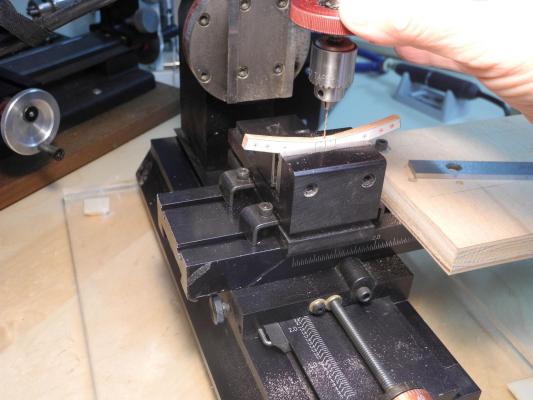
Hi Ed: I've become a major fan of the pin-indexing method - thanks for introducing us to it. On the frames I place a hole on each side of each joint. Consequently there are enough pinning holes that if one is slightly off I can avoid using it and still get good results. I mounted the vise that way simply because I wanted the opening towards the front of the mill - less turning of the hand wheels when going from drilling the pin holes to drilling the floors. The opening in the vise doesn't change since all the floors are the same thickness, so I can use a regular allen key to loosen and tighten the vise.
- 649 replies
-
- 4
-
-
- dunbrody
- famine ship
- (and 2 more)
-
Hi Greg Brian is correct. I saw this saw in the NRJ and have had it for a couple of years. Highly recommend it.
- 649 replies
-
- 5
-
-
- dunbrody
- famine ship
- (and 2 more)
-
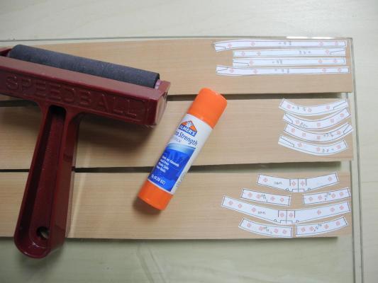
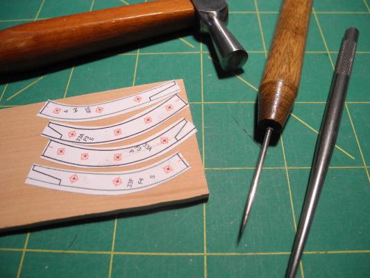
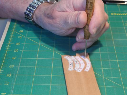
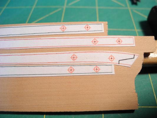
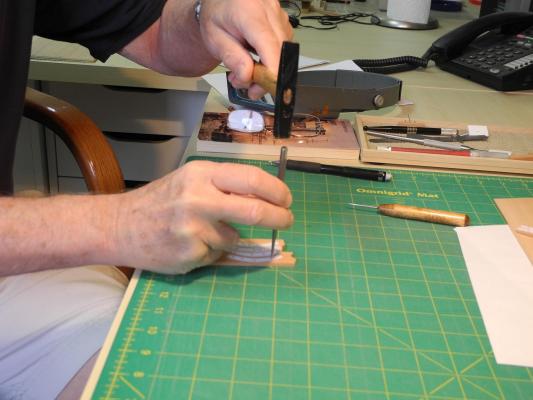
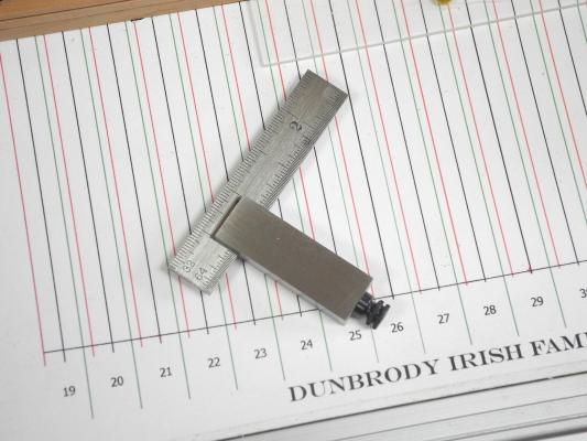
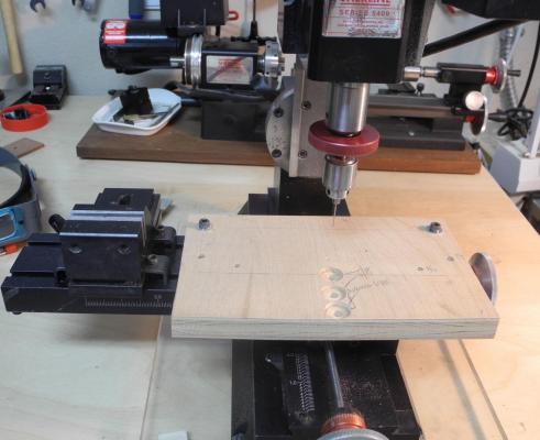
Part 7 - Frame Construction The frame construction process can be broken down into three general phases: 1. Forming the individual components of the fore and aft frames. 2. Adding the chocks to the fore and aft frames. 3. Assembling the fore and aft frames and joining them for the frameset. Since there are many individual steps in each phase of frame construction I will treat each phase as a separate topic. Phase 1 – Forming the individual components of the fore and aft frames Step 1. After printing multiple copies of each fore and aft frame drawing for the frameset (at least 2 copies, more if rework is needed), the components from the frame drawings are then cut out and glued to the appropriate stock, using an Elmer’s School Glue stick. The Floors and First and Second Futtocks use 11/64 stock. The Third and Fourth Futtocks use 9/64 stock. The Rising Timbers and Stanchions use 7/64 stock. Step 2. The locations of the holes for pin-indexing then need to be prepared. The process begins by making a very small pilot hole (really not more than a pin-prick) with a small awl. This pilot hole is then used to accurately locate a center punch, and with one tap of a small hammer the hole is enlarged to the approximate size of the drill for indexing. Step 3. The components are then cut out on the scroll saw, leaving approximately 1/64 of waste outside the lines. Step 4. The holes for pin-indexing are then drilled, using a #63 drill in the Sensitive Drilling Attachment of the Sherline milling machine. Step 5. Any rough edges from the cutting or the drilling are then cleaned with a fine sanding stick (220) to eliminate small particles that may affect alignment in future steps (learned through experience!) Step 6. The initial detailed shaping of the floors is performed: a. On the disk sander, the ends of the floors are trimmed down to the joint lines and the bottom of the floors are sanded to the outline b. The floors are temporarily pinned together with the pattern facing out for each floor. c. The notch in the floors to fit over the keel are cut out and shaped with a file - I use files for most of the shaping required for the frames. I use coarse (00 and 0) followed by medium (2). A spare piece of keel material is used to check alignment with the rabbet and the centerline. d. The limber holes are then cut. A line is drawn for the each side of the limber hole, using a Starrett No 14 square, which I’ve found to be a valuable tool in this build (I’ve had it for years and rarely used it until now). Using a small saw, a stop cut is made on these lines - the outside edges of each hole - then some of the material is pared out from between the stop cuts to make a groove. The shaping of the limber holes is completed using a round escapement file. e. The boundaries of the cutting down line are marked on the top of the floors. The top of the floors are flattened to accept the keelson and sister keelsons, following the lines marked off for this area. f. A centerline is marked across the top of the floors. The floors are then unpinned and the mounting hole for each floor is drilled in the center of the top of the floor using the #63 drill. (For this build, I keep my Sherline Mill set up as a ‘drilling station’, using a mill vise for clamping and a piece of waste material for drilling the pinning holes) This completes the prepping of the floors, which is most of the work in this phase. Step 7. The individual frame components are trimmed for an accurate fit. Futtocks 1 (for the Aft frame of the frameset) or Futtocks 2 (for the Fwd frame) are pinned to the pinning template (both port and starboard futtocks). Then the floor is pinned to the template so that it slides down to overlap the futtock, and a line is drawn on the futtock to reflect the outer edge of the floor. This marks the butt joint on the futtock. The joint is then trimmed to the line using the disk sander. This process is followed for each butt joint in the frames. The scarf joint is marked the same way, but is finished to the line using files. This completes the first phase of Frame Construction. The two frames of the frameset are now ready for installation of the chocks.


- 649 replies
-
- 22
-
-
- dunbrody
- famine ship
- (and 2 more)
-
Hi Patrick: Thanks - I'm happy with the progress, even with all the do-overs. I had to add two whole frame sets (4 frames) to the scrap pile today when I discovered that they were off. This led to a revision in the way I'm assembling them - I hope it solves the problem. And, at this point, don't even talk to me about doing the whole ship! If I tried that I don't think I'd get very many of my 'punch list' done. I wish I made the kind of progress you're capable of.
- 649 replies
-
- 4
-
-
- dunbrody
- famine ship
- (and 2 more)
-
Thanks Mark and Ed. I'll abandon the 'pin' approach and use the PVA glue. I tried using a small spot on the spall, which is made of poplar, and it came off easily.
- 649 replies
-
- 5
-
-
- dunbrody
- famine ship
- (and 2 more)
-
Thanks for the suggestion Mark - I'll need to think that through. I'm not sure I could use the pinning approach for the spall if I left them on, so I'd need to come up with a way to attach them on top as you said. Any ideas on what kind of glue, how much to use, and how to get them off?
- 649 replies
-
- 4
-
-
- dunbrody
- famine ship
- (and 2 more)
-
Thanks Mark. I'll be sending an email out in the next day or so.
- 649 replies
-
- 3
-
-
- dunbrody
- famine ship
- (and 2 more)
-
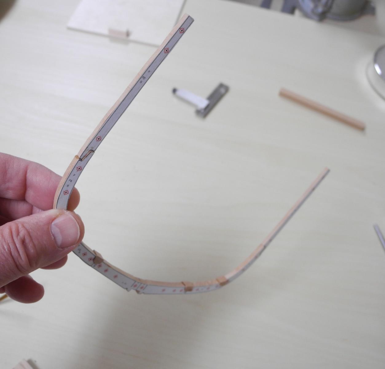
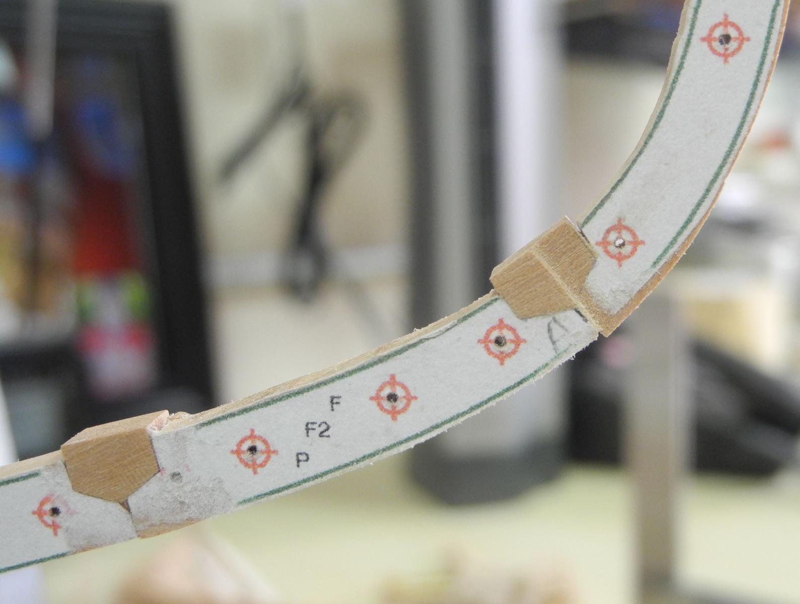
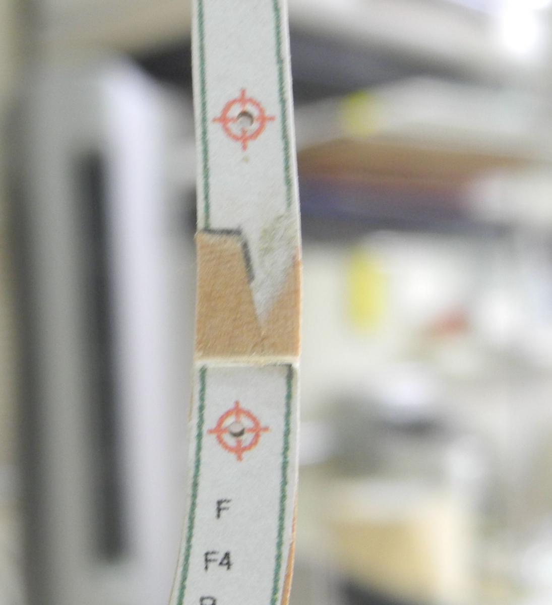
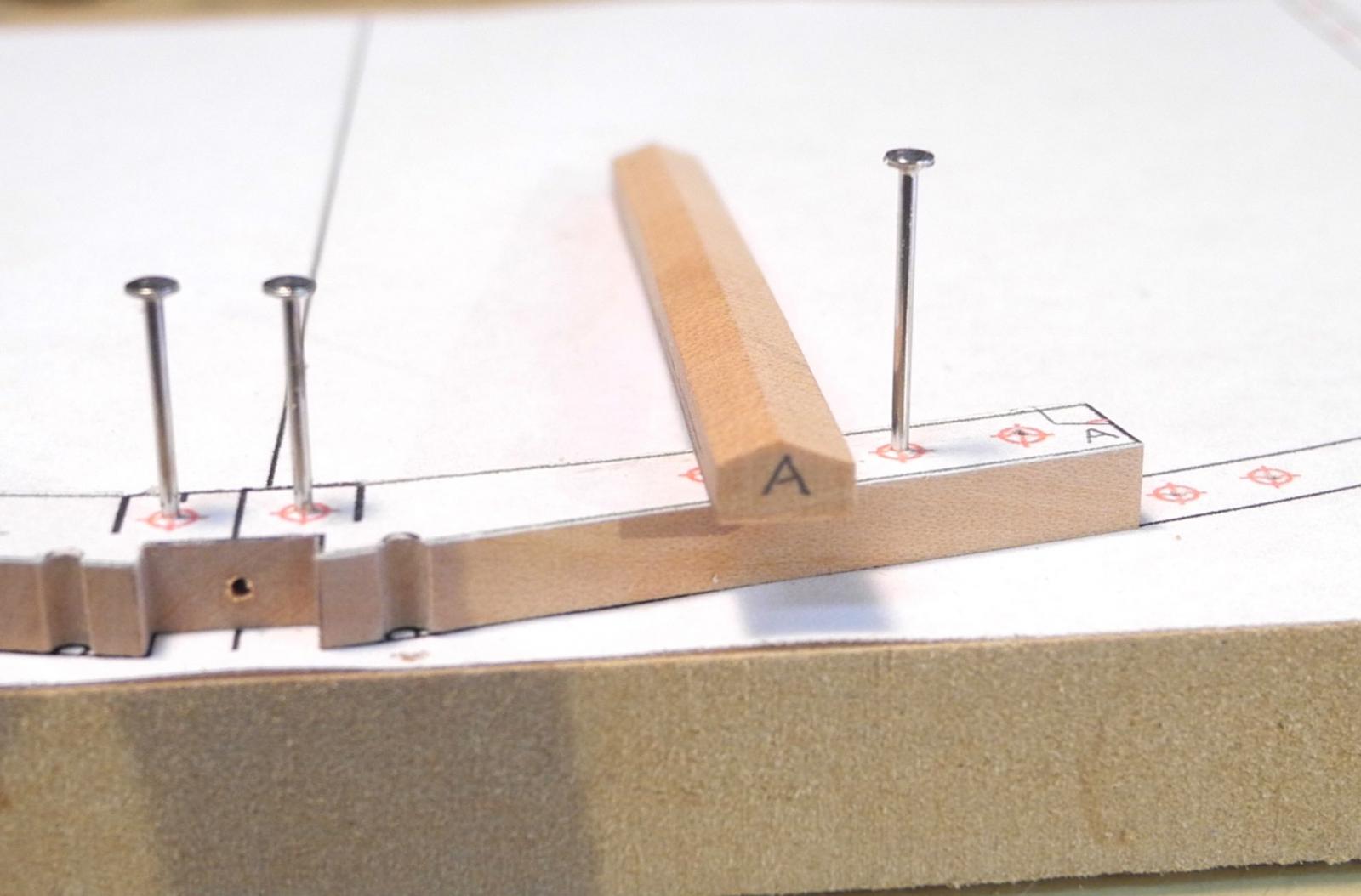
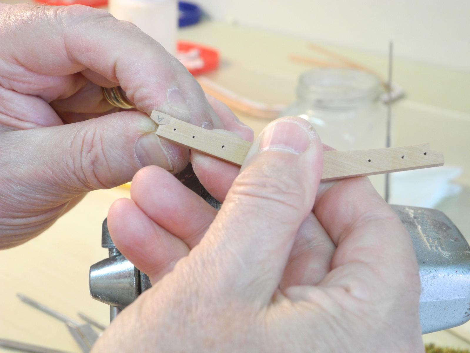
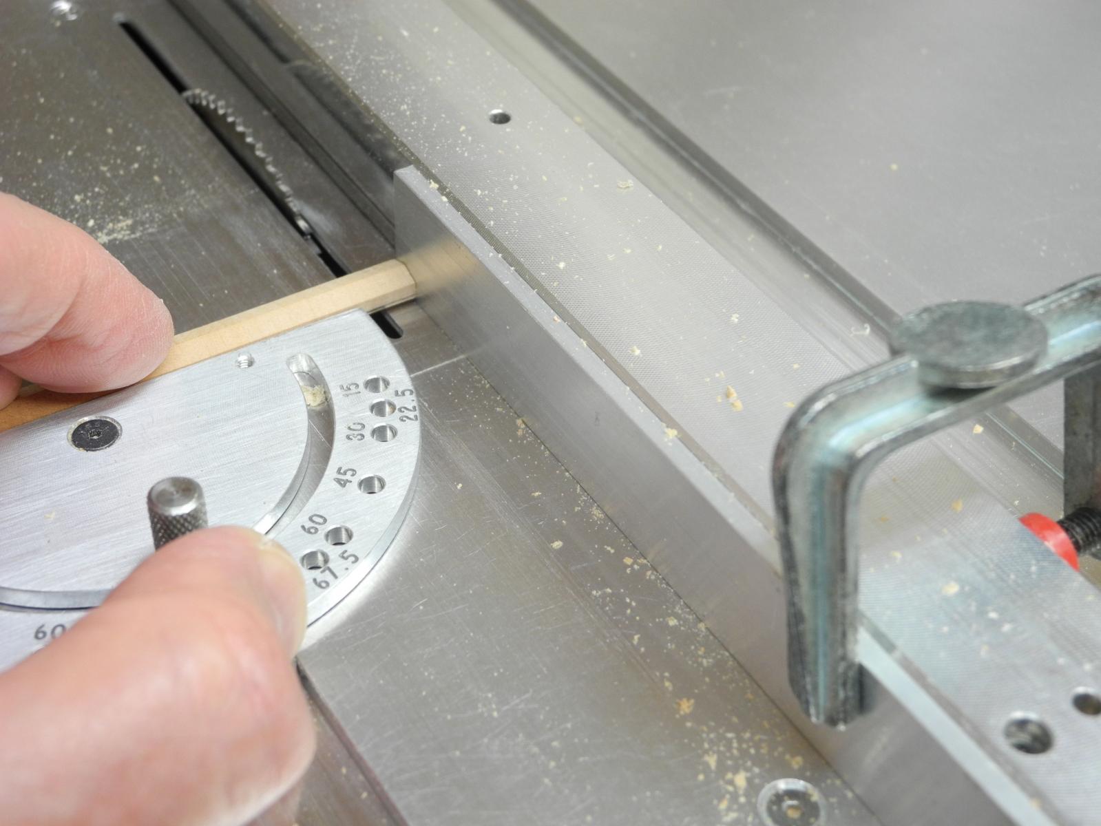
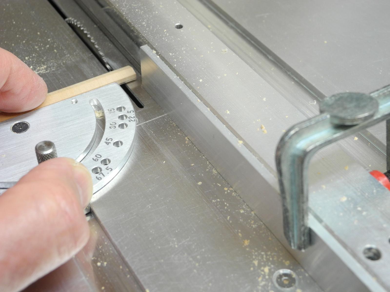
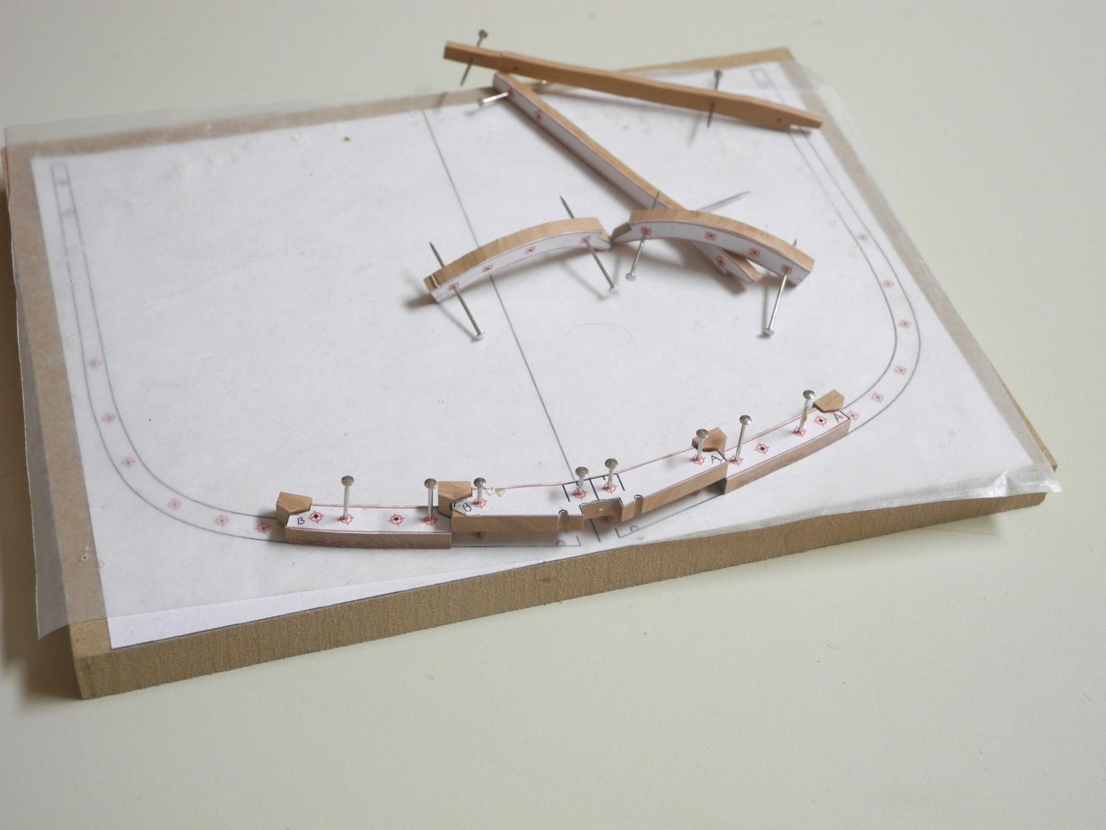
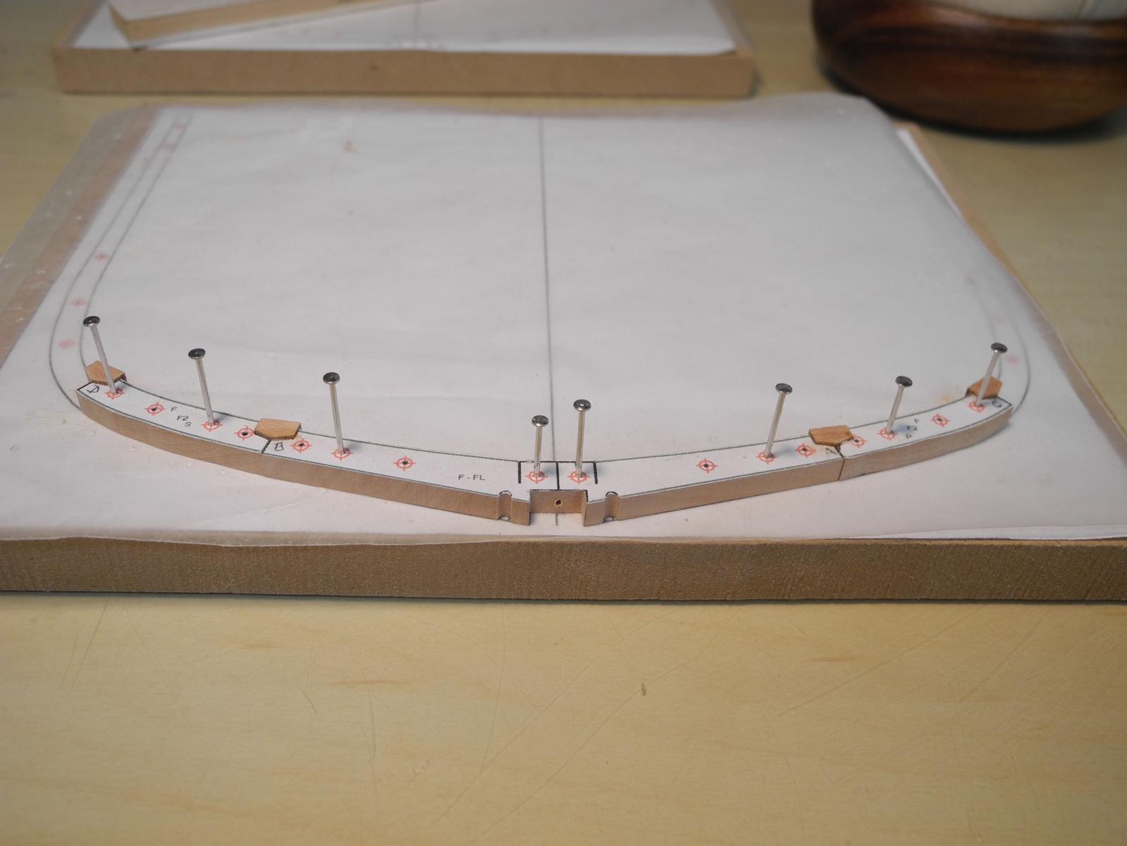
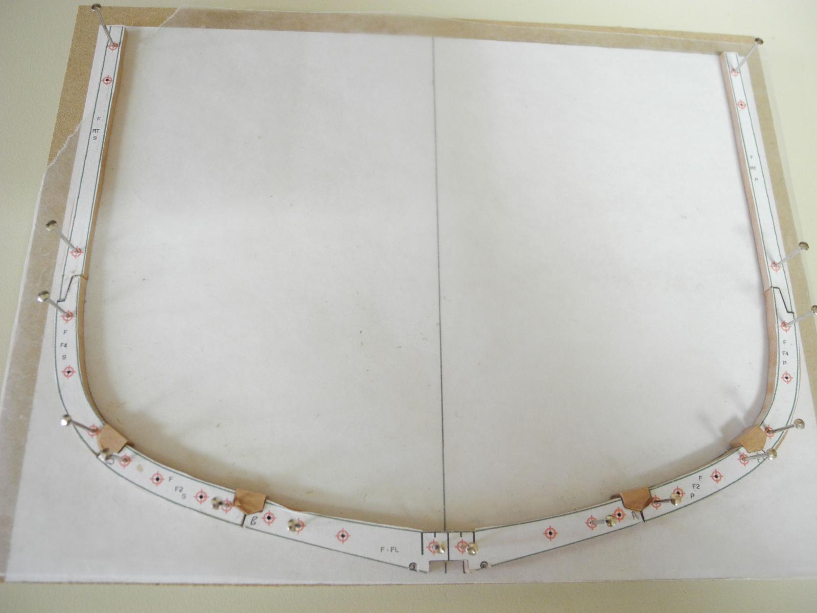
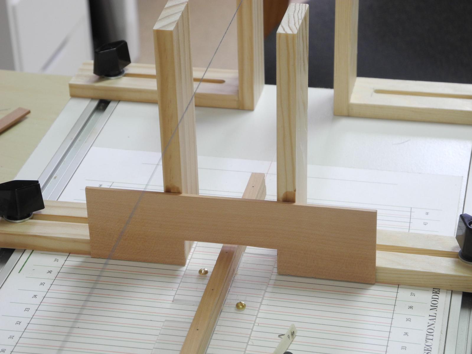
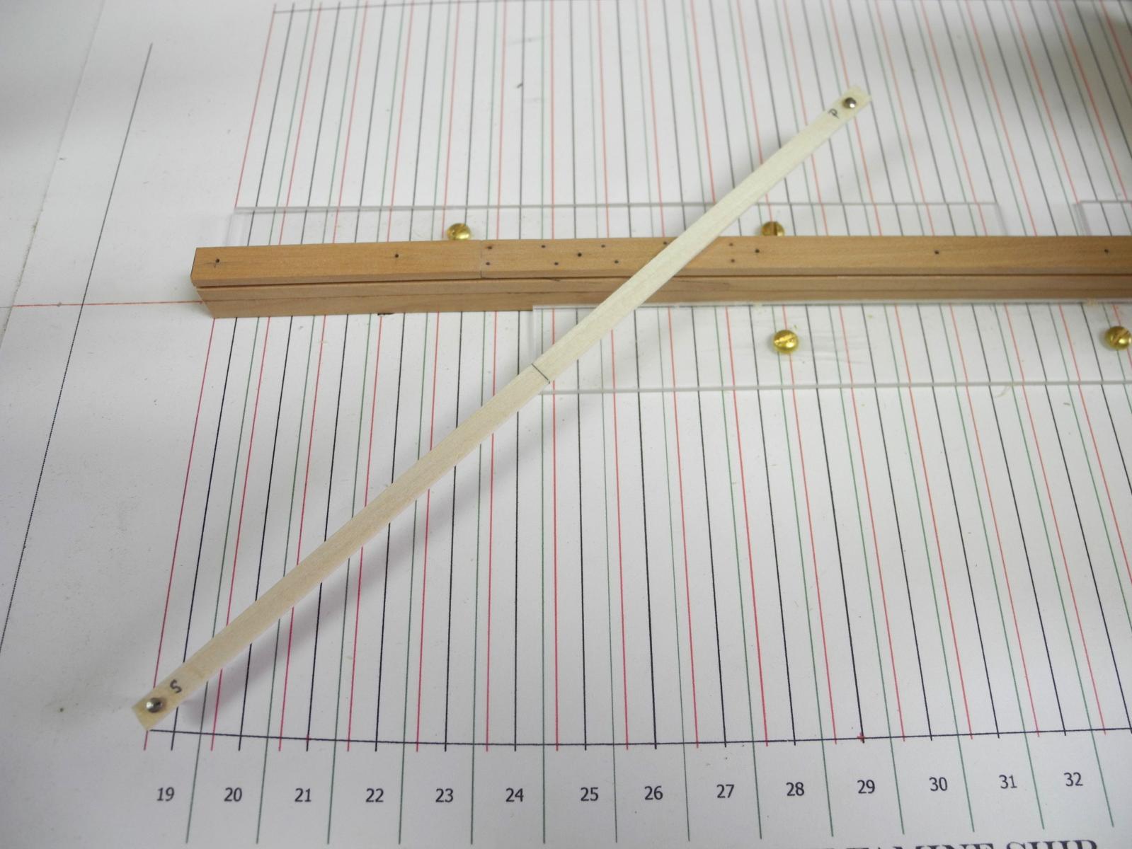
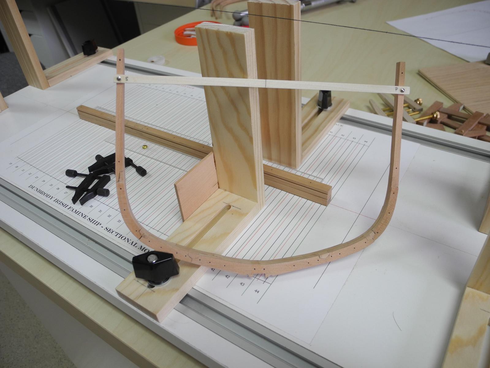
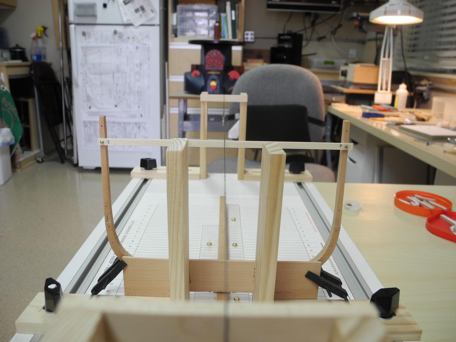
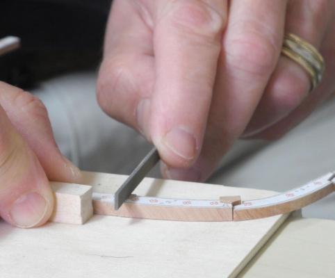
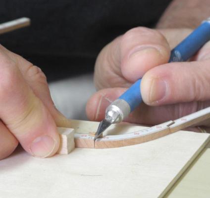
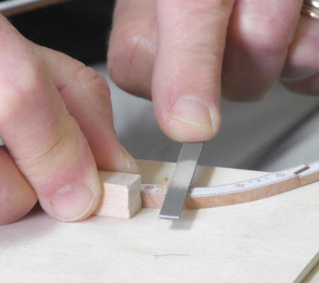
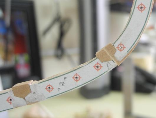
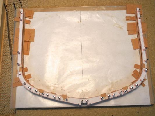
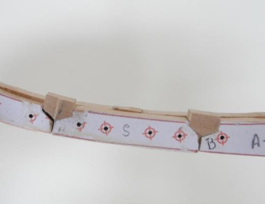
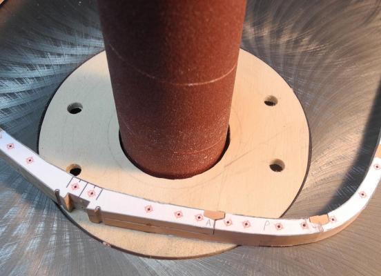
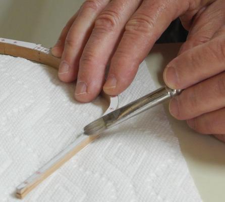
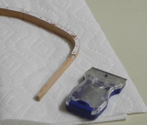
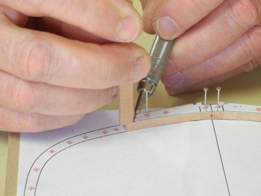
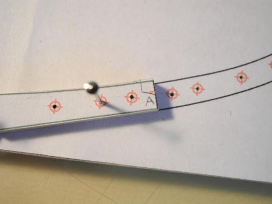
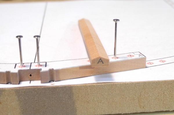
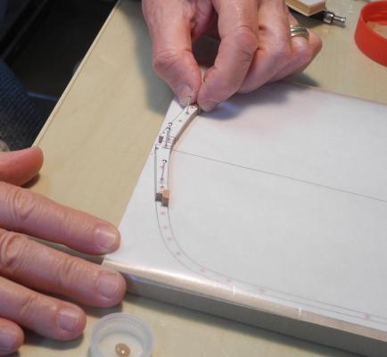
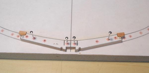
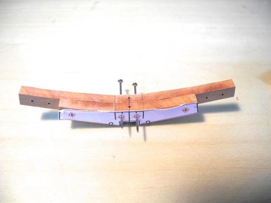
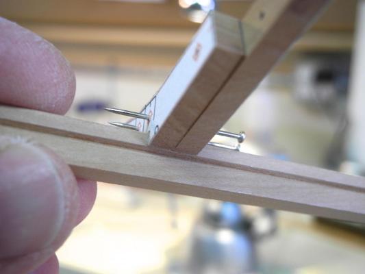
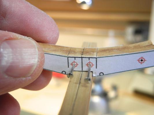
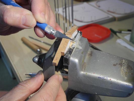
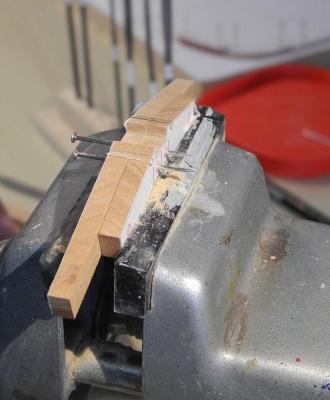
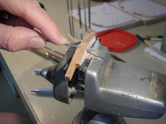
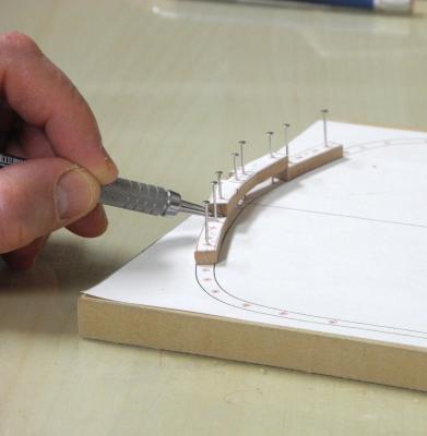
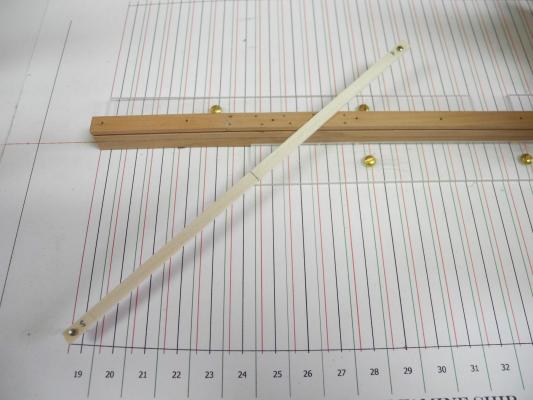
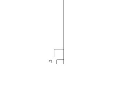
Part 6 – Frame Installation I was going to begin the description of the frame construction process, but I’ve been thinking a lot about the installation of the frames, and I think I’ve come up with a workable approach. I’d appreciate any comments, suggestions for improvement, cautions, etc., that anyone cares to make. The frames are separated by approximately 5 inches (actual), which would be slightly less than 7/64 at 1:48 scale. This doesn’t leave a lot of room for clamping. I do have some small machinist’s clamps (from Lee Valley woodworking) that I’ll use. I decided to use a flat piece of wood mounted vertically on the shipway as a clamping fixture. The wood is 3/32 thick and I made sure that it lay flat and that the bottom edge was flat against the shipway. The length of this fixture is just greater than the span of the frame at the second futtocks (this is the extent of the largest sided dimension of the frame). I cut out clearance for the keel and the pieces holding the keel. As Druxey already suggested, I want to use a cross-spall to check that the frame is perpendicular side-to-side. In thinking about how to secure this cross-spall, I decided to pin it to the frame, using the lower of the two pinning holes at the top of the frame. This will position the cross-spall within 1/8 inch of the string used to mark the centerline, making it easy to line up the centerlines. Since most (possibly all) of the frames will be of the same width at top, I can reuse the cross-spall. Pins will make it easy to mount and unmount the cross-spall, so I cut some pins down to a length that will not interfere with adjacent frames, and CA glued them to the spall so I wouldn’t lose them. The ends are marked S for starboard and P for port, to avoid any fit issues, and the centerline is marked on all four sides of the spall. The following photo shows the spall attached to a frame. A test mount of a frame, aligning the centerline of the cross-spall with the centerline string seemed to work. So, hopefully this is the approach I will use for mounting the frames. As I said earlier, though, I am very open to any comments, criticisms (I know they’re constructive), or suggestions.


- 649 replies
-
- 20
-
-
- dunbrody
- famine ship
- (and 2 more)
-
Thanks Druxey. I've been thinking about using cross-spalls (EdT seems to use them frequently), but I have a question on glueing them 'temporarily'. Can you explain the type of glue you use and how you separate them when the frame is securely in place? There isn't going to be a lot of room between frames, and I'm afraid any jostling in trying to get a cross-spall off may upset things.
- 649 replies
-
- 6
-
-
- dunbrody
- famine ship
- (and 2 more)
-
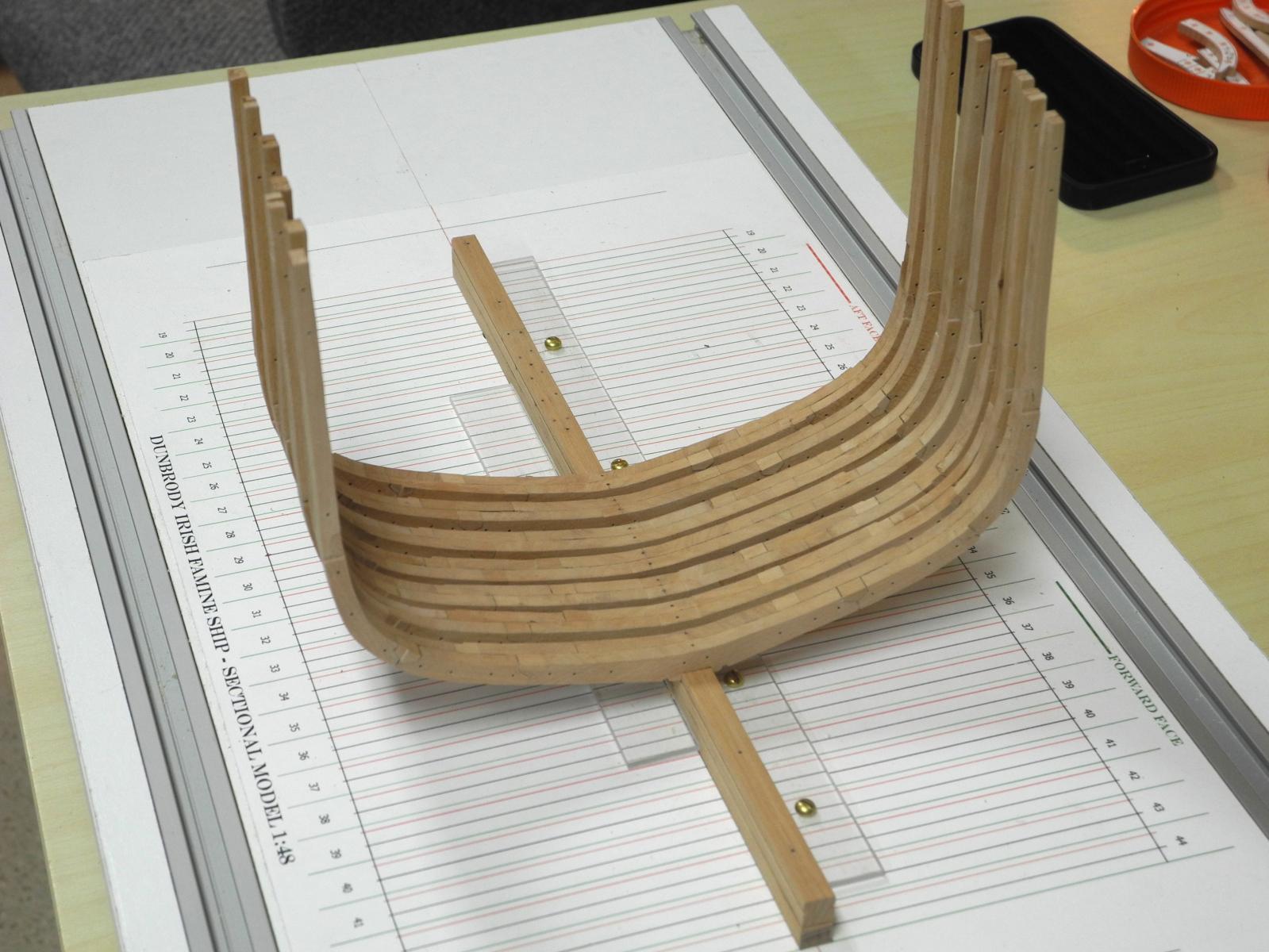
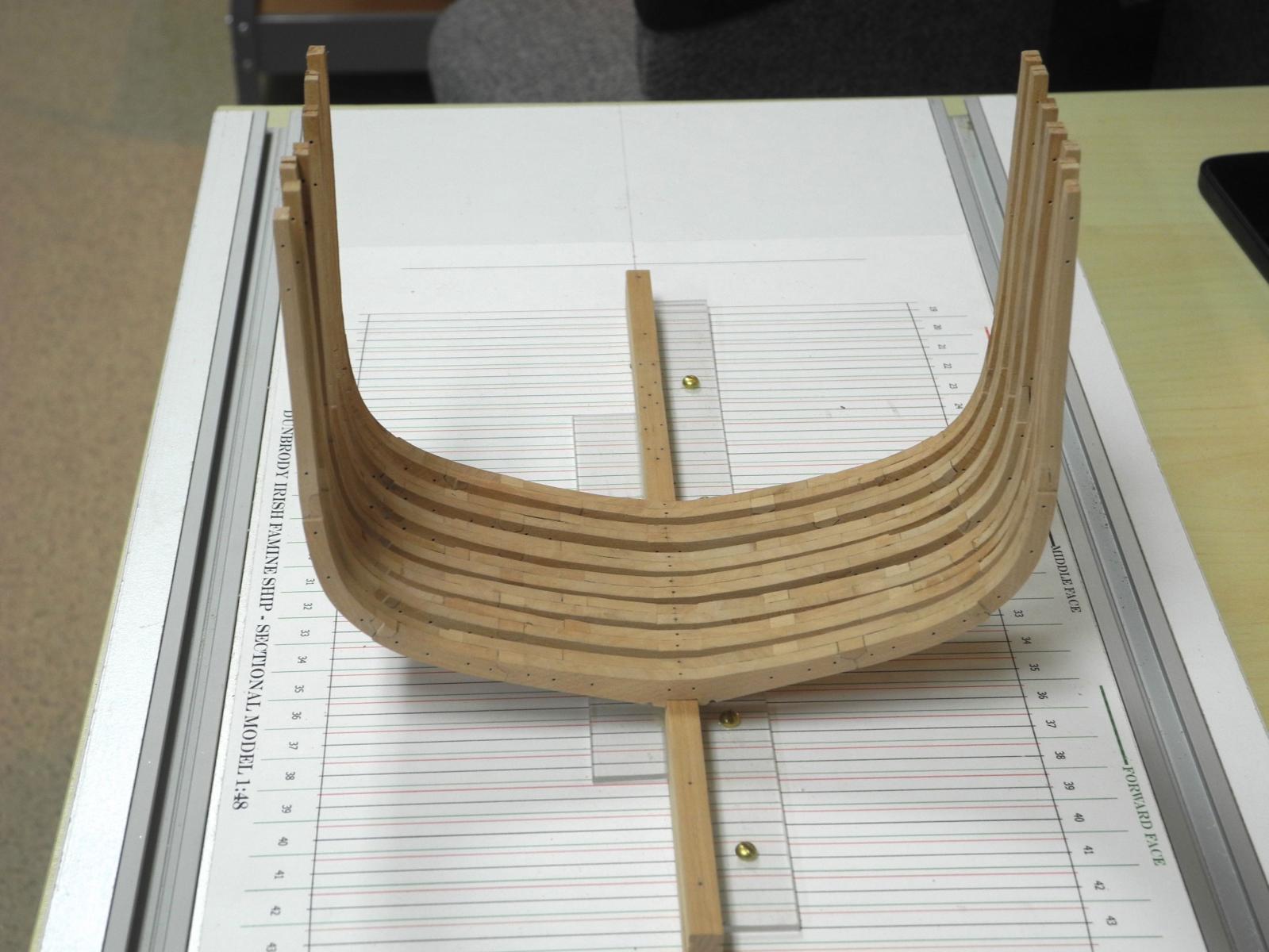
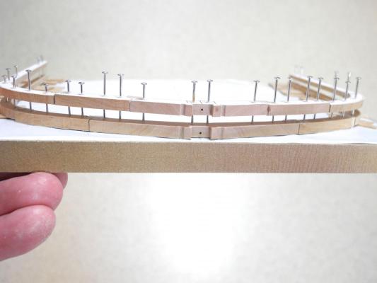
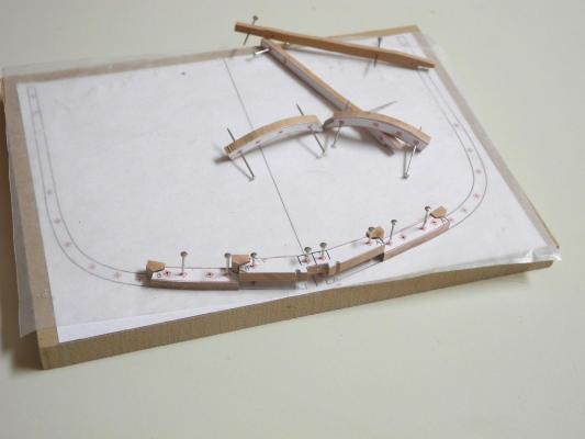
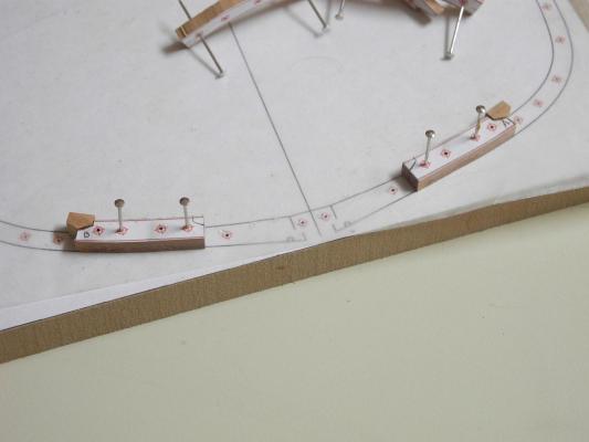
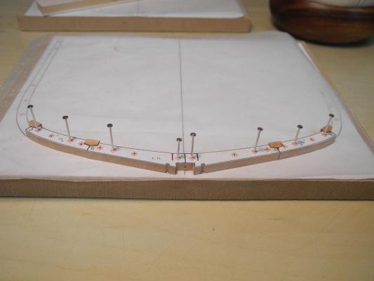
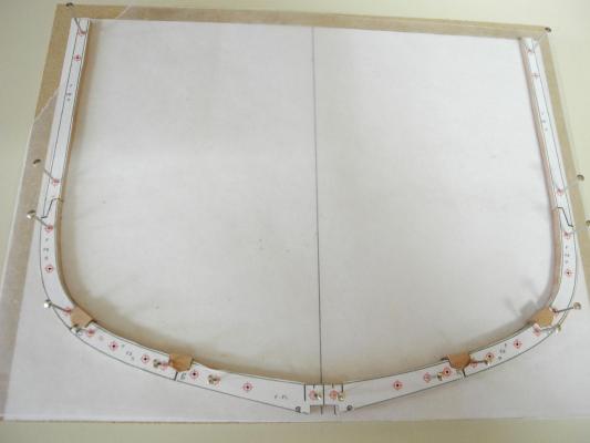
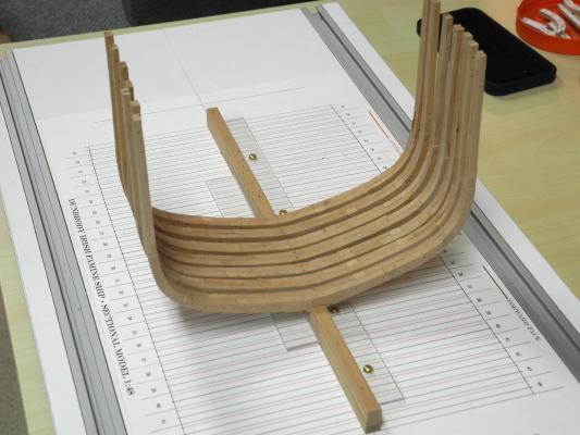
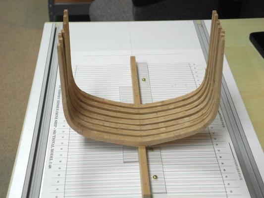
The process for building the frames is fairly long and complex, and I'm still trying to put it down in a form that makes sense to everyone who looks in. In the meantime, I've completed the first 7 framesets or frame pairs and I wanted to see how they look on the keel. The frames are NOT permanently in place, they're simply laid on the keel. The notch in the bottom of each frame is fairly tight, so it holds them in place. As I install them permanently I may need to loosen the notch here and there for proper alignment. I'm still thinking through an effective way to make sure they're correctly aligned when installed. Here's what they look like in their temporary install: Thanks everyone for the likes and comments.
- 649 replies
-
- 23
-
-
- dunbrody
- famine ship
- (and 2 more)
-
LOL!! I wish you were right. There was a lot of trial and error in trying to get the build correct.
- 649 replies
-
- 4
-
-
- dunbrody
- famine ship
- (and 2 more)
-
Thanks Elijah. I looked in on your build and I'm very impressed. Welcome to a great hobby - I only wish I started at your age instead of waiting to start many, many, many years later. Better late than never, though.
- 649 replies
-
- 6
-
-
- dunbrody
- famine ship
- (and 2 more)
-
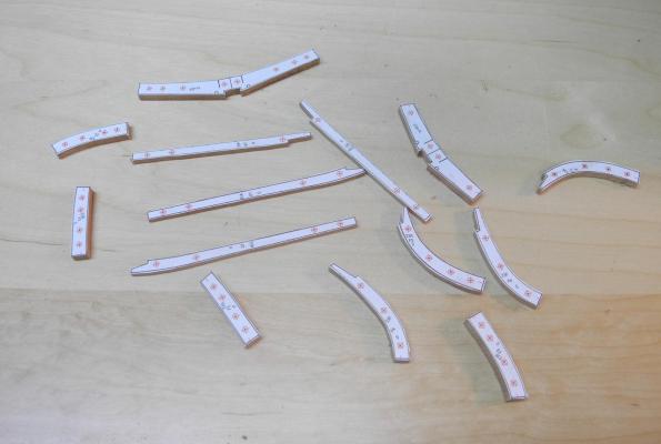
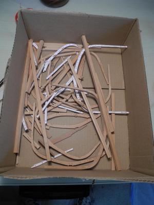
Soon?? I've made a whole lot of sawdust just trying to get the process right. Lots of fun, though. Here's the current state of my scrap box - I expect it will keep growing over time - I hope I have enough Madrone!
- 649 replies
-
- 11
-
-
- dunbrody
- famine ship
- (and 2 more)
-
Hi Elijah: I'm a latecomer to your build log, but I'm very impressed with your progress - especially considering you're new to this hobby. Keep up the great work.
- 701 replies
-
- 2
-
-
- phantom
- model shipways
- (and 1 more)
-
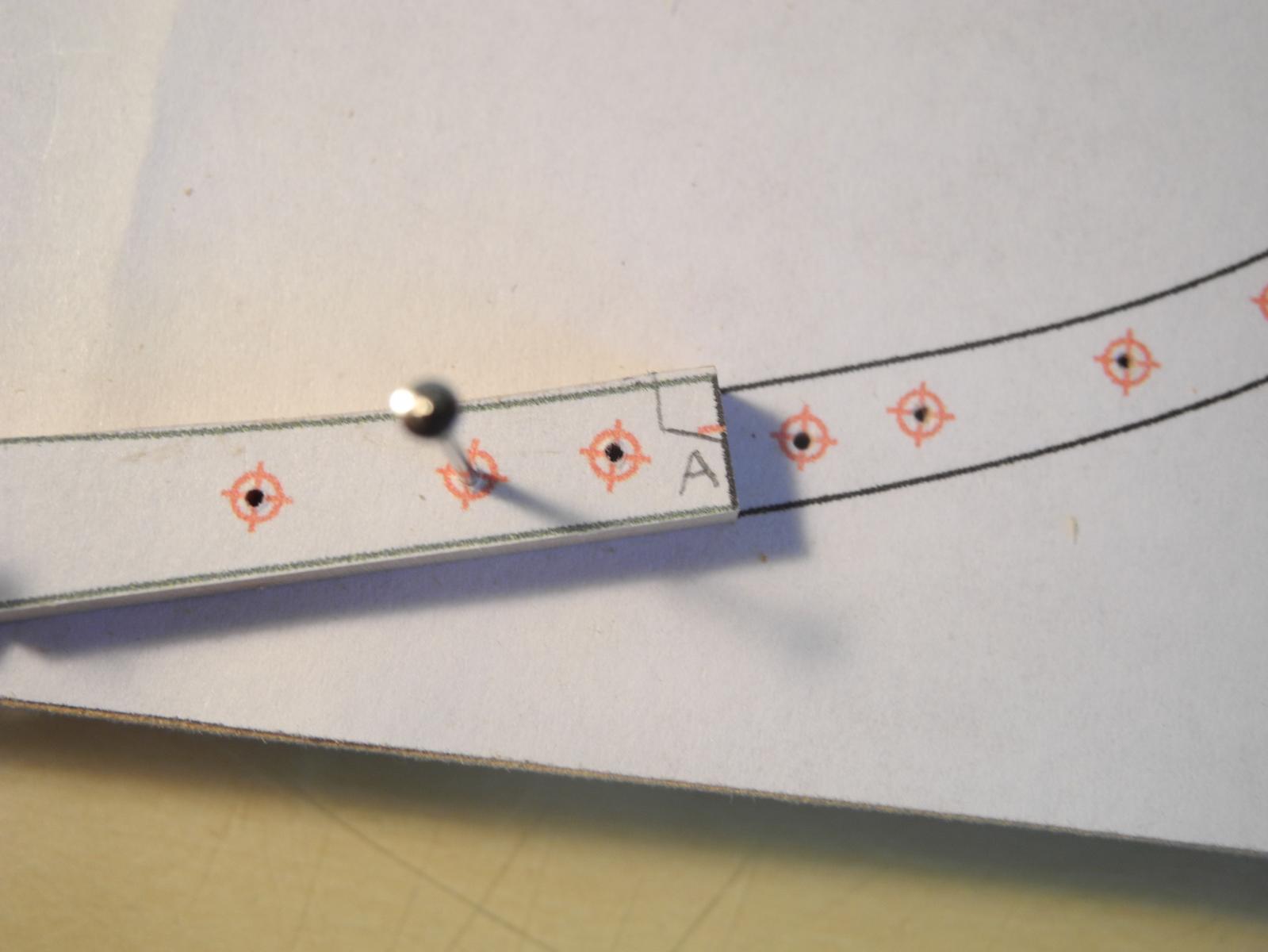
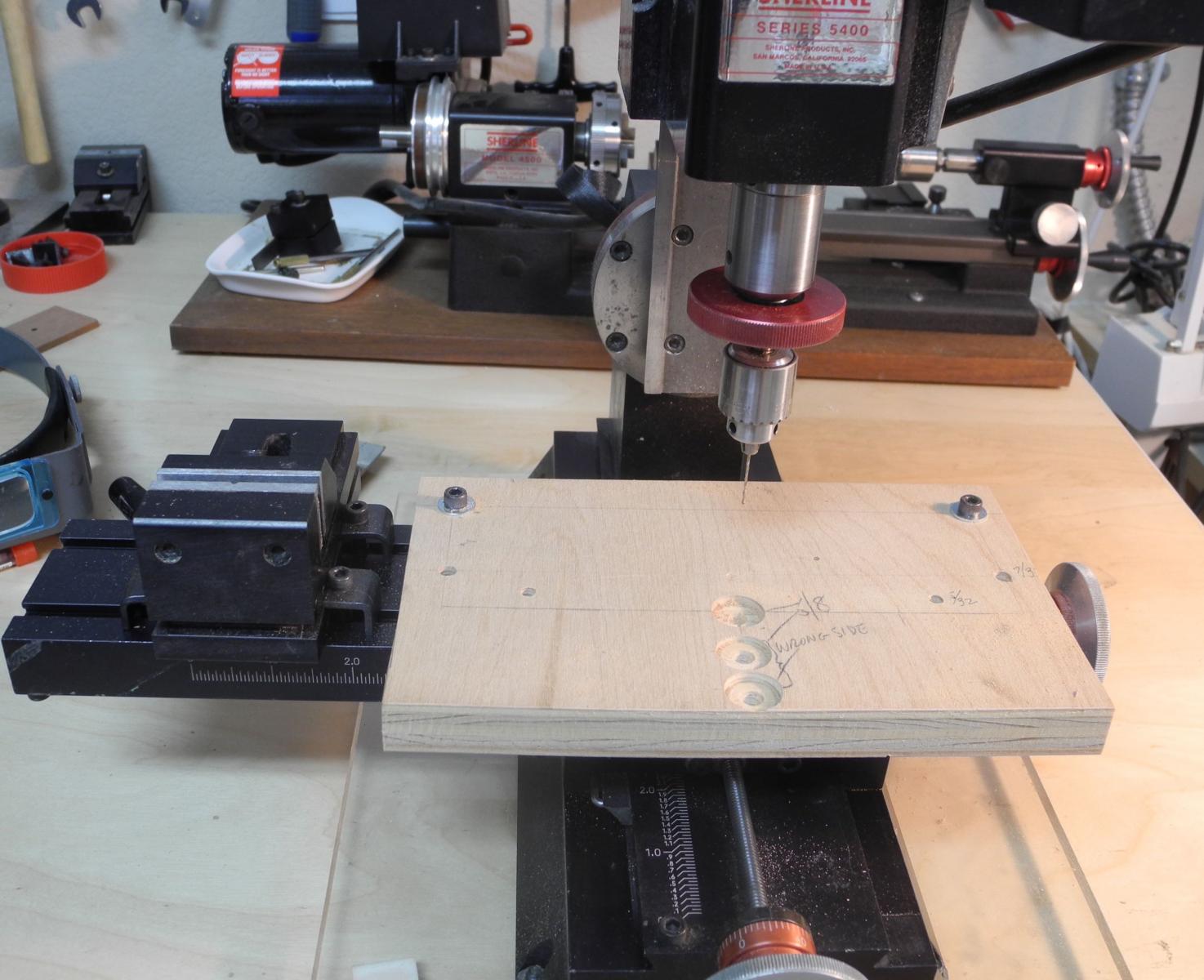
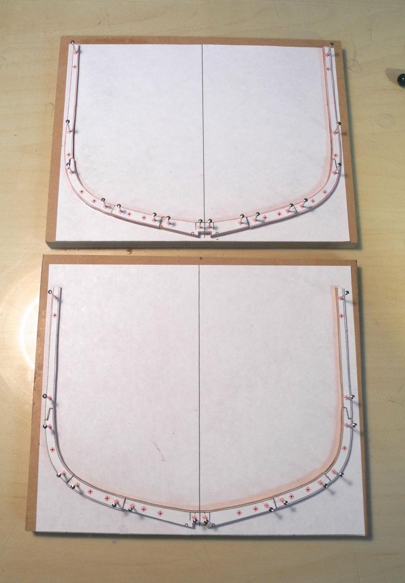
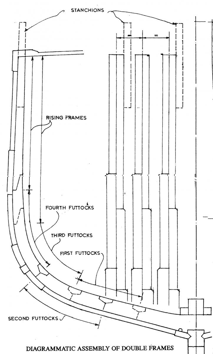
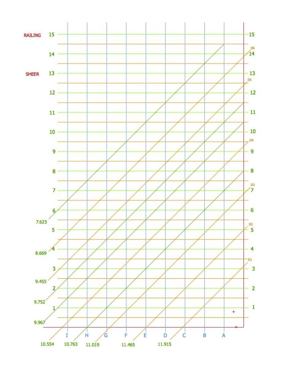
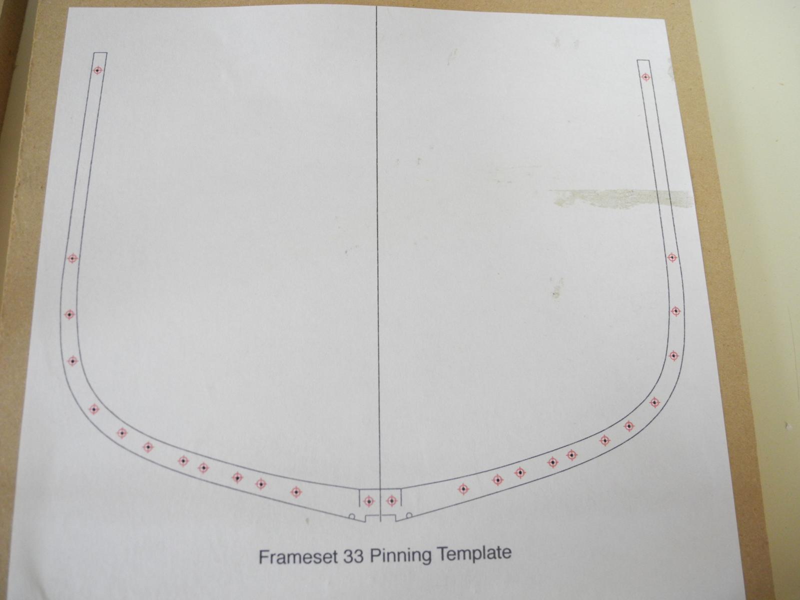
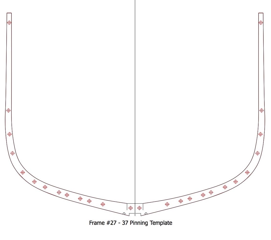
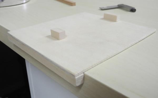
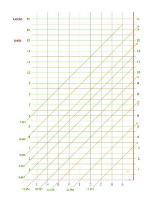
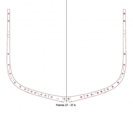
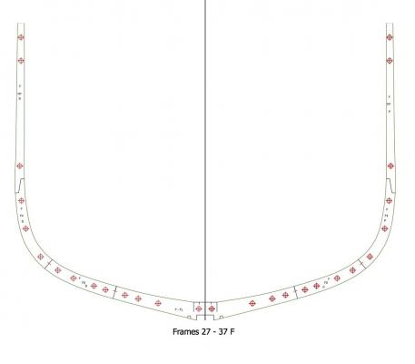
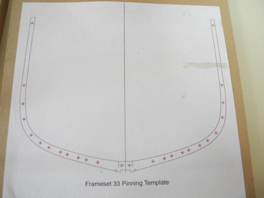
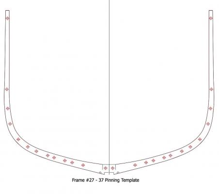
Part 5 - Dunbrody’s Frames The Crothers book describes a “Long and Short Floor” System for building square frames. Its principal feature is the staggering of floor butts in adjacent frames and the absence of first futtocks butts over the keel. The Dunbrody plans appear to employ this framing approach. The cross-section view of the frames from the Dunbrody construction plans show the frames as having parallel sides, with the sided dimension of each higher frame timber decreasing. Each of Dunbrody’s frames contain the following components: Floor 4 Futtocks (2 on the Starboard side, 2 on Port) 2 Rising Timbers (Top Timbers) In addition, every other frame contains 2 bulwark stanchions. From the plan, it appears that these stanchions are part of the forward frame of even-numbered framesets. The joints between the Floors and the Futtocks, and the joints between the Futtocks themselves, are strengthened by frame chocks, 4 for each frame. The joints between the topmost futtocks and the Rising Timbers are strengthened by the use of a simple scarf joint. Since the frames are paired into framesets, and since the joints between components are offset from one frame of a pair to the other, it seems to me that the use of chocks and scarf joints is overkill. The two books (by Crothers and Desmond) that I’m using as additional references show frames that are paired, but nowhere do they show the use of chocks or scarf joints within these frames. In conversations with others and within my own thinking I keep revisiting the idea of eliminating many of the chocks and scarf joints, since most of the framing detail will be eventually hidden. The chocks and scarf joints add a couple of hours of work for each frameset (if all goes well, more if they cause rework). Nevertheless, my goal is to build Dunbrody as she is depicted in the plans that I have, so I intend to be true to those plans as much as possible. I also feel that focusing on getting this joinery correct is (hopefully) going to make me a better modeler. The first order of business in modeling Dunbrody’s frames was to develop a method for drafting each frame. A set of layers was used to allow printing different views. The first layer is the template itself. No drawing is done on this layer – it is used as a guide for locating the various components that need to be drawn. The right edge is aligned with the Y axis at 0, and the base is aligned with the X axis at zero. The vertical lines are the buttock lines and the horizontal lines are the waterlines. The diagonals serve two purposes: the brown lines labeled D1 through D6 will determine where the chocks and scarf joints are placed. Along with the other diagonals they will be used to mark the moulded dimension at the point the diagonal crosses the outer frame line. The numbers to the left of the each diagonal indicate the moulded dimension at that point. The next layer is the Drafting Points layer, which initially is blank. This layer is used to plot the points that will be the basis for drawing the curves for the outer and inner edges of the frame. Each face of the frame has a layer: The Aft Layer is the aft face of the aft frame of the frameset. The Middle Layer is the forward face of the aft frame or the aft face of the forward frame, as required. The Forward Layer is the forward face of the forward frame of the frameset. The Aft Layer and the Forward Layer are initially blank. The Middle Layer has permanent lines that indicate the Cutting Down line (the level area at the top of the frame where the Keelson and Sister Keelsons will be installed) and the dimension of the notch that will fit over the keel. It contains a semi-circular arc that will be the limber hole in the frame, and it also contains the centerline used for mirror imaging during drafting and for aligning the center of the frame during building. (The above image is enlarged and cropped so these details are more visible) The remaining layer is the Pinning Template, and is used to place the pins for each frameset (more about this below). As part of the planning for the build, the values for waterlines 1 through 6 were determined for each frame. The values indicated that frames 27 through 37 are identical, so that the same drawing can be used for each of those frames. In addition, the sheer changes only for those frames at the extreme forward end of the sectional model, and will be barely noticeable at 1:48. I’ve developed a process for making these frames that I’m comfortable with. The process is highly dependent on the ‘Pin-Indexing’ approach introduced by Ed Tosti in his Young America build. This approach has helped bring my modeling to another level of accuracy already, and I intend to employ it whenever the opportunity is there. As mentioned above, the frame drawings include pin locations as a separate layer within the file, which I refer to as the Pinning Template. The Pinning Template is printed separately and glued to a piece of MDF (medium density fiberboard). The idea is that this MDF-based template can be re-used without the holes being enlarged due to subsequent uses. The middle 11 framesets of the model are identical, so those templates will be re-used often. After gluing the Pinning Template to the MDF, the holes for the pins are then carefully drilled. The accuracy of this drilling will be critical to the success of the building process. The following photo shows the template glued to the MDF and drilled. The holes are a tight slip fit for the pins, allowing flexibility for removing and re-inserting the individual components as necessary. The next topic will describe the frame construction process.

- 649 replies
-
- 13
-
-
- dunbrody
- famine ship
- (and 2 more)
-
Thanks Mark, Nigel, and Alan. I'll try to get a look at those sources, but they don't sound like they refer to merchant ships from the mid 1800's. At any rate, I've committed myself to following the Dunbrody plans, whether or not they're historically accurate.
- 649 replies
-
- 6
-
-
- dunbrody
- famine ship
- (and 2 more)