HOLIDAY DONATION DRIVE - SUPPORT MSW - DO YOUR PART TO KEEP THIS GREAT FORUM GOING! (89 donations so far out of 49,000 members - C'mon guys!)
×


Mahuna
-
Posts
1,504 -
Joined
-
Last visited
Content Type
Profiles
Forums
Gallery
Events
Everything posted by Mahuna
-
 Thanks Druxey. I thought the same thing about the direction of the scarphs, based on my reading of the Desmond and Crothers books. However, this is just one of the discrepancies I've discovered between the Dunbrody plans and those books, so I'm planning on following these plans. Thanks Owen. I've taken a lot of measurements from the plans to build a Table of Scantlings. If you're interested send me a PM and I'll forward the Excel file to you. Similarly, if you want any of the drawings I've done in TurboCad I'd be happy to share them with you. Thanks Nigel. That's a very interesting point, since as you say the ship was built in Quebec. However, the naval architect (Colin Mudie) who designed the Dunbrody replica ship was working from scantlings and survey documents only, so it may also be that this is his interpretation of how the ship was actually built. If you can recommend any books on French and/or British ship design from the 19th century I'd be very interested. Thanks Nigel. I think showing and explaining the steps helps the reader understand the process I'm following (right or wrong), and hopefully will prompt someone to point out a different or better way of doing something, which I would greatly appreciate.
- 649 replies
-
- 10
-

-
- dunbrody
- famine ship
- (and 2 more)
-
I agree on the Rub n' Buff - just a little at a time and buff it in well. I've used this product on models and on outdoor lamps that had become very weathered - made them look brand new, but doesn't give a harsh glare.
- 641 replies
-
- 2
-
-
- greenwich hospital
- barge
- (and 1 more)
-
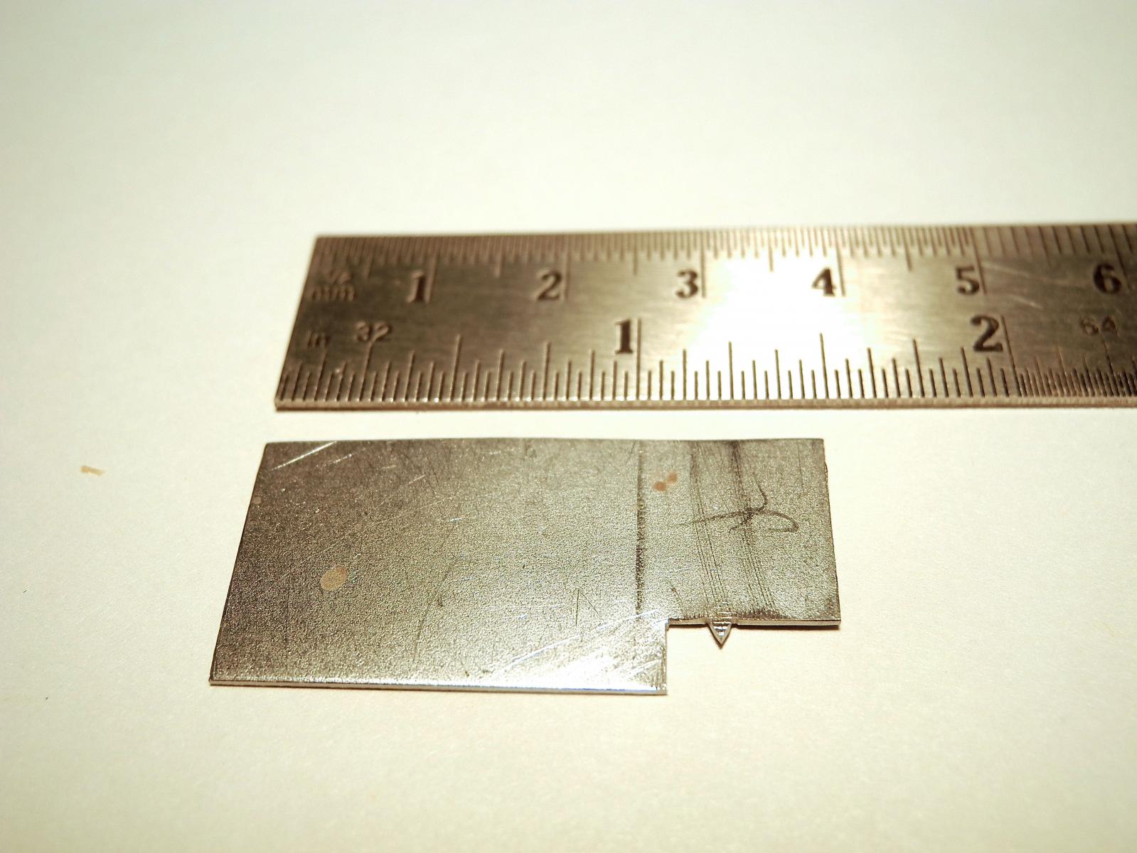
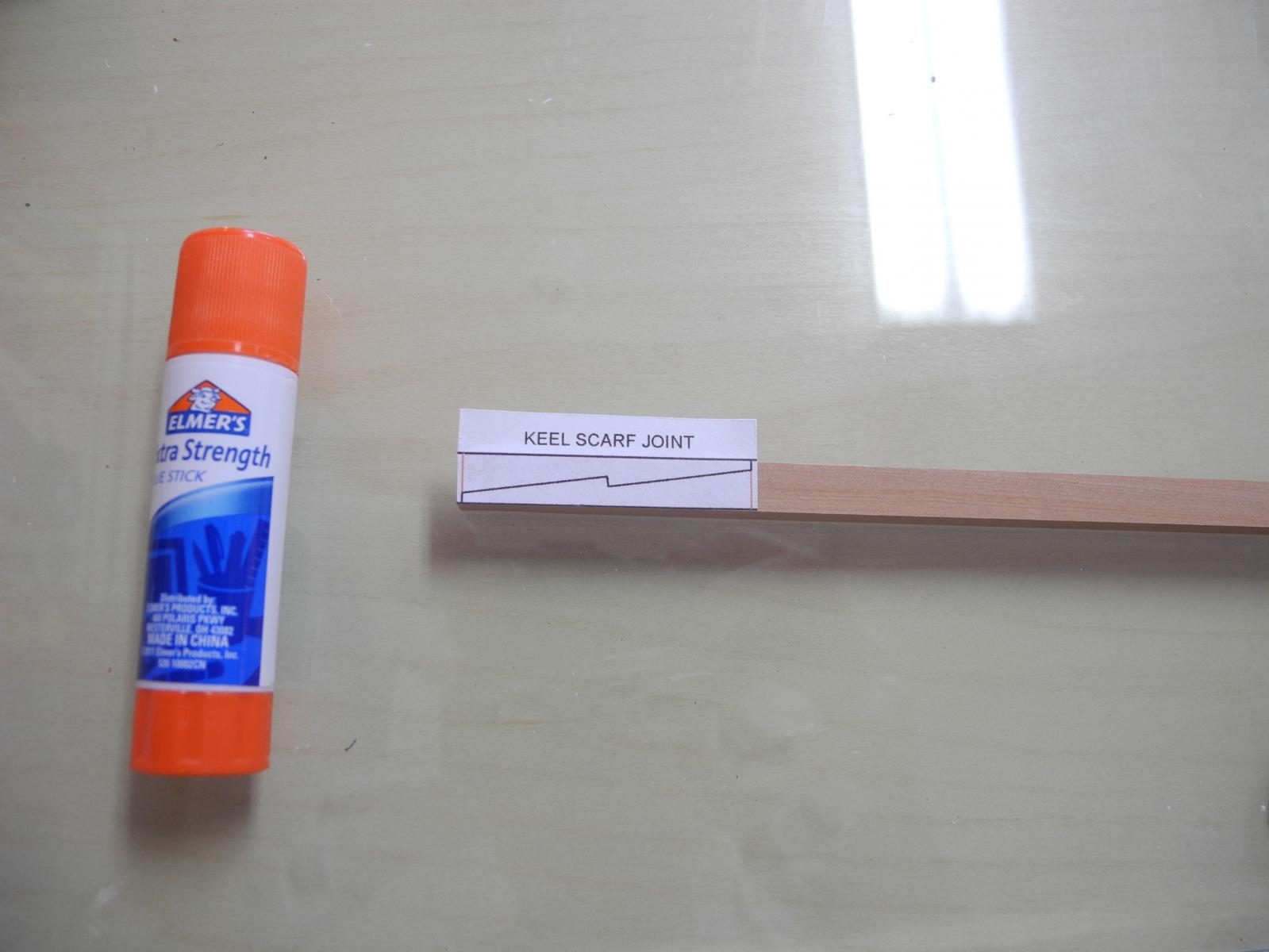
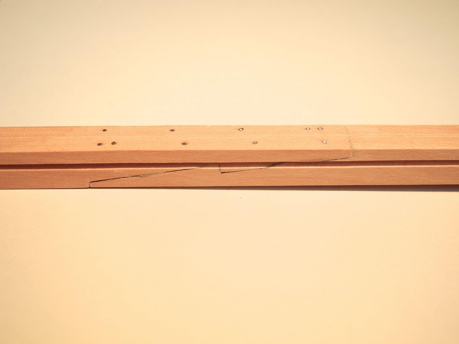
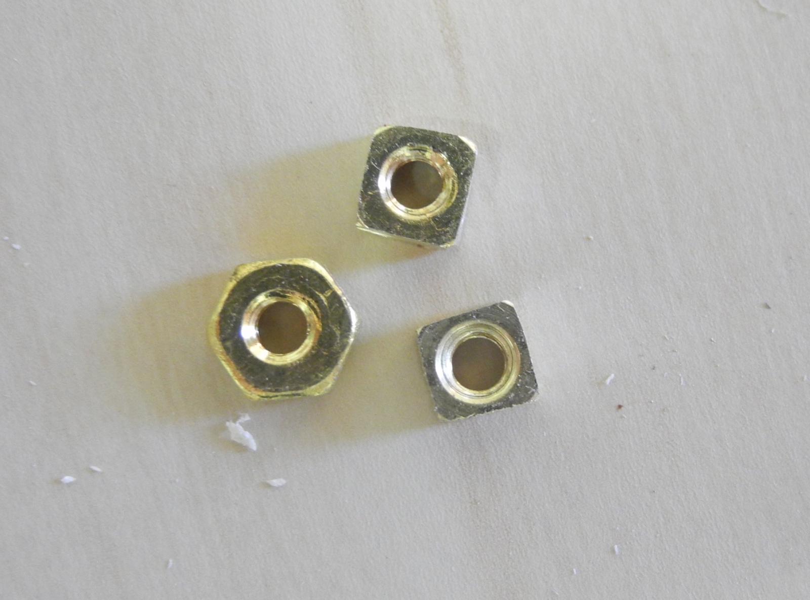
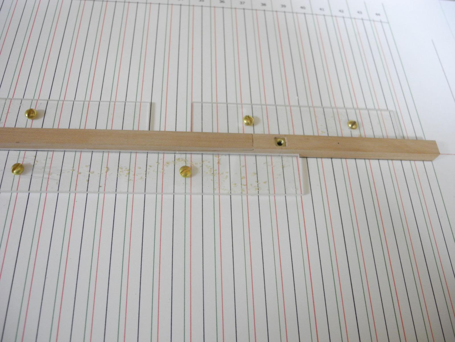
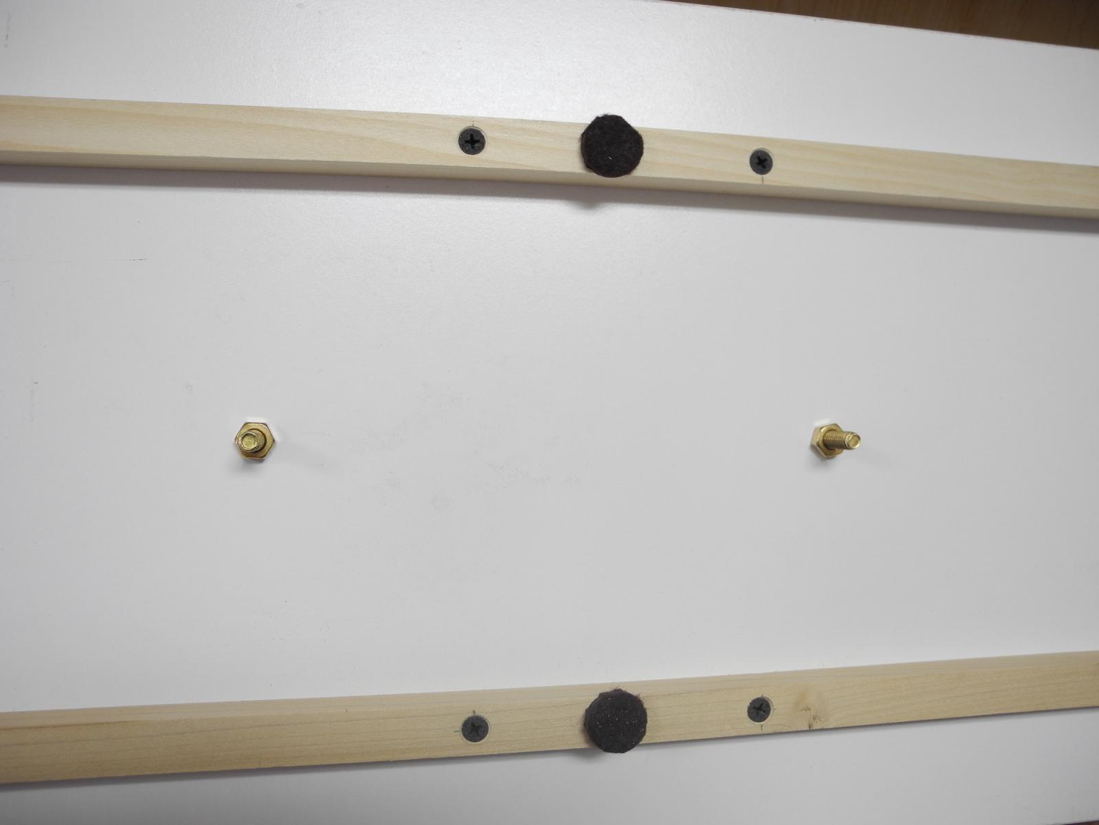
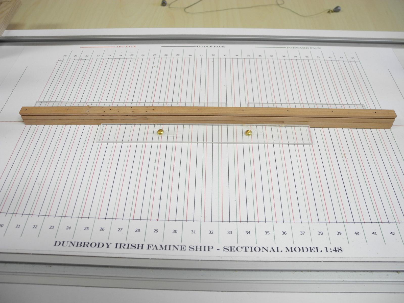
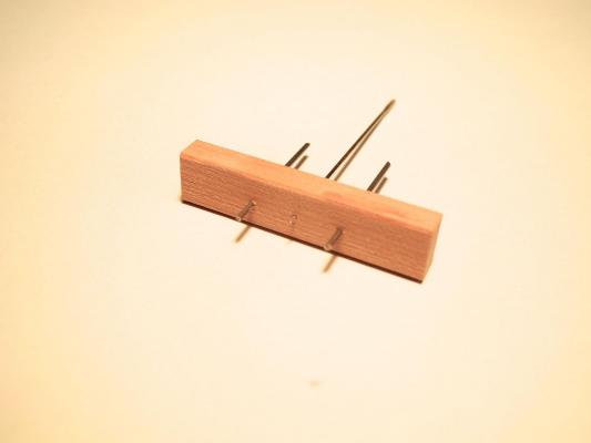
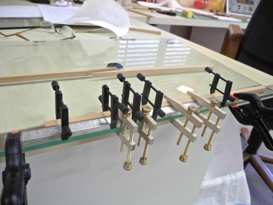
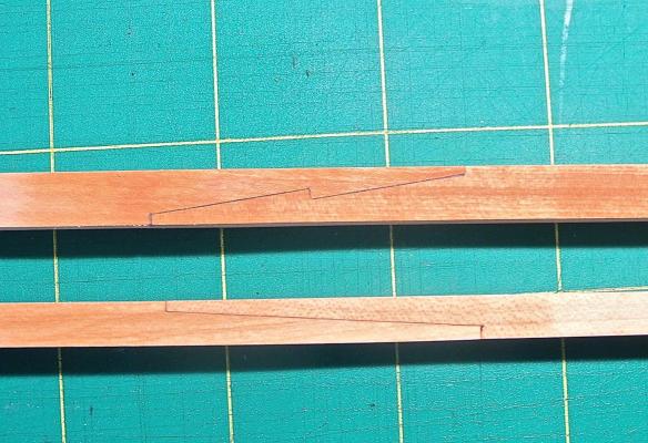
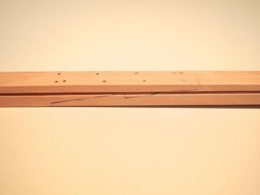
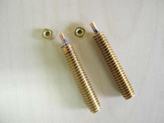
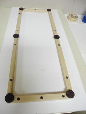
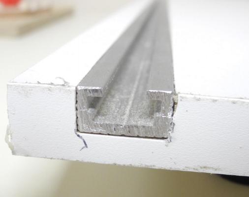
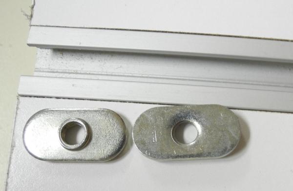
Part 4 – The Keel Assembly Dunbrody’s Keel, as measured from the construction plan, is 14 inches square. There is a rabbet that starts approximately 5 inches down from the top of the keel. Below the keel is what the plans call a False Keel, which has a breadth of 14 inches and a depth of 9 inches. My reading of the Crothers and Desmond books shows that typically a False Keel is installed to protect the keel from damage due to grounding or striking an obstacle, and as such is relatively thin at 1 – 4 inches, is installed in a fashion that would allow it to be easily replaced, and has only simple butts to join its components. The depth of Dunbrody’s False Keel seems to be much larger than expected, and the construction plan shows the parts of the false keel joined by a nibbed scarf joint. I’ve found several items in Dunbrody’s construction that are very different than the construction described in the Crothers and Desmond books. I’ll point these out as I go along, but my intent is to reproduce the Dunbrody plan as far as possible. The keel at 1:48 would be .292 inches, or a little over 18.5 64ths. To simplify the model construction, I’ve reduced this to 9/32. After milling some appropriate lumber I needed to mark a centerline on the keel and found this to be fairly difficult with a pencil and ruler. I had seen a woodworker’s centering device that consisted of two outside rods with a pencil in the middle, all equidistant from each other. I made a miniature of this using stiff piano wire as the outside rods and a medium needle as the marking device instead of a pencil. Drilling the holes at the correct distances was fairly easy using the calibrated wheels of the milling machine. I also needed a way to cut the rabbet. Since the sectional model is the middle of the ship the keel is straight and flat, so the rabbet will be the same throughout the model. I decided to use a scraper type of device similar to what Ed shows in Young America. I drafted the profile of the rabbet in TurboCad. I then pasted this profile onto a piece of 18 gauge stainless sheet and cut the shape of the rabbet cutting tool using a jewelers saw and files. Before cutting the rabbet, though, I needed to create a hooked scarf joint in the keel. I drafted the pattern for the hooked scarf and used a glue stick to paste it to the wood to be cut. This being my first hooked scarf, there was a lot of trial and error, and the scrap box started filling up. As part of making the joint, I needed to set up a clamping arrangement that would ensure the two pieces of the keel stayed straight and level while being glued. I used a straight piece of aluminum stock as a straight edge, and clamped this to a piece of ¼ “ plate glass as a flat base. I then used an arrangement of clamps that would keep the keel tight against the straightedge and the glass surface, making sure that the joint itself was properly clamped. The nibbed scarf of the False Keel can be seen in the background, awaiting gluing. I decided to work on the nibbed scarf of the False Keel at the same time as the Keel’s hooked scarf. The following photo shows the end result for both joints. When I was reasonably happy with the joint on the keel I fastened the joint using the bolt pattern described in the reference books and then cut the rabbet. In prior builds I’ve always neglected to address mounting requirements until the end of construction, and then have run into difficulties getting a mount that is secure and attractive. I decided on this build to use the approach from both Naiad and Young America, which is to use mounting bolts that attach to nuts that are embedded in the False Keel and then covered by the Keel. The size of the False Keel limited my choice of threading, so I used 4-40 nuts. Even this nut size was too large to comfortably embed in the false Keel, so I filed the nuts square to reduce their size and to simplify the cutting required for them. The following photo shows an original 4-40 nut and the two that were reduced to square. Since the mounting bolt needed a shoulder to prevent it from being run too far into the False Keel, I decided to center drill a ¼-20 threaded rod, and to solder an appropriate length of 4-40 threaded rod in the hole. This is satisfactory at present, but I think I’ll replace the bolt with a one-piece bolt with two different thread sizes, as in Ed’s work. The false Keel was then mounted on the shipway. This was followed by gluing the Keel to the False Keel, effectively hiding the mounting hardware. I used spring clamps to ensure that the Keel and false Keel were properly aligned, and pins to secure the joint from the top. This completed the installation of the Keel Assembly. In the next post we’ll start discussing the construction of Dunbrody’s frames. It will be a few days before the next post – company arrives tomorrow to enjoy the beautiful Arizona weather, so the shipyard will be closed for a few days.


- 649 replies
-
- 23
-
-
- dunbrody
- famine ship
- (and 2 more)
-
Welcome Ken. I love the Cork area, especially along the coast.
- 649 replies
-
- 4
-
-
- dunbrody
- famine ship
- (and 2 more)
-
Welcome John Hi Patrick Depends on your definition of 'long' - one step at a time.
- 649 replies
-
- 4
-
-
- dunbrody
- famine ship
- (and 2 more)
-
Hi Brian Now, when will you be starting your new build log??
- 649 replies
-
- 5
-
-
- dunbrody
- famine ship
- (and 2 more)
-
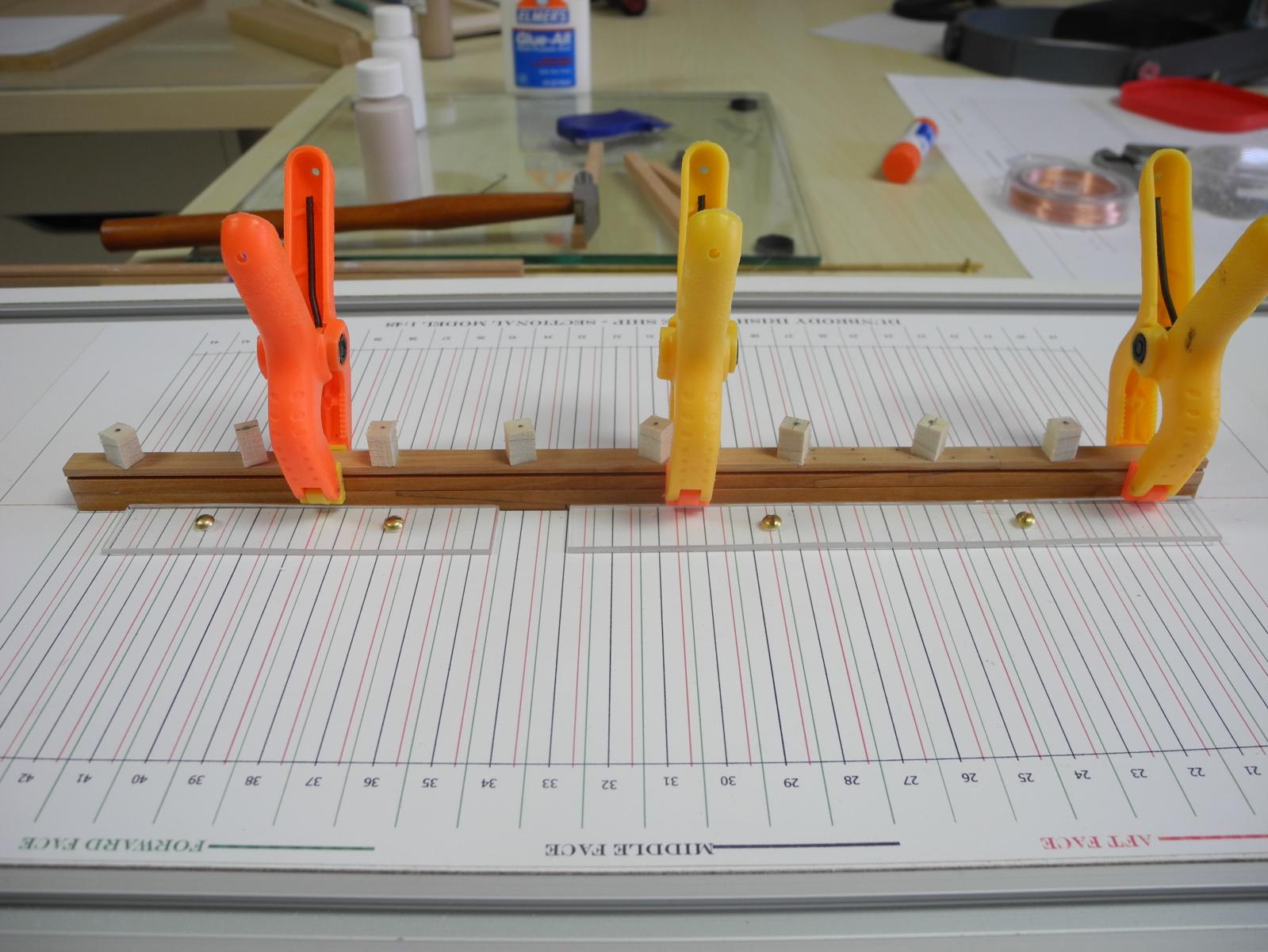
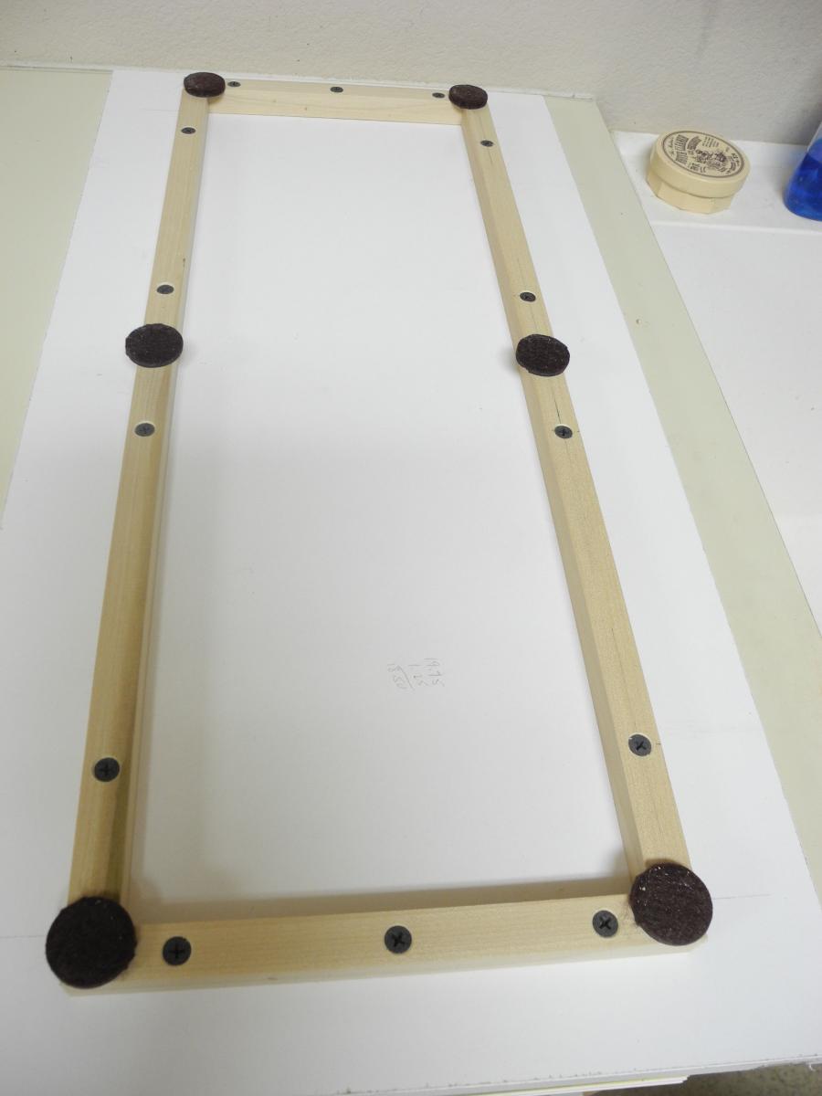
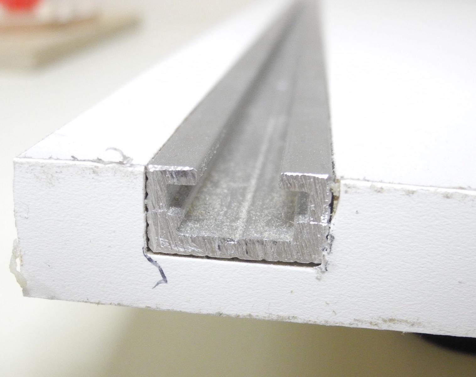
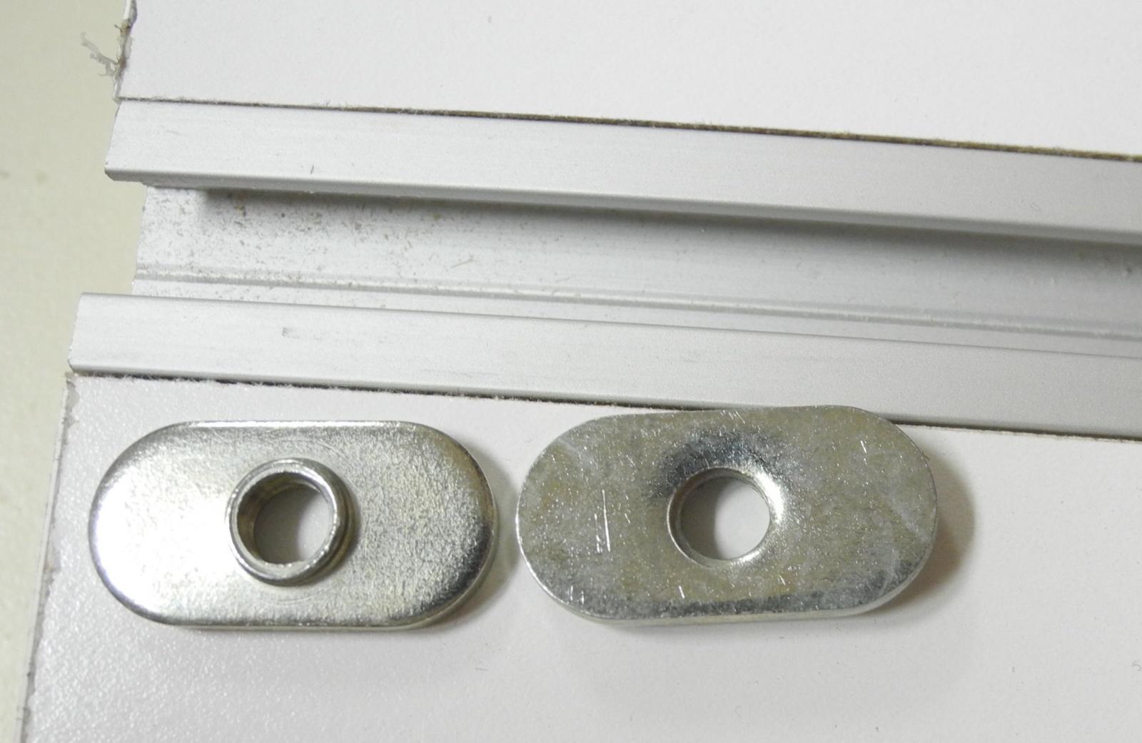
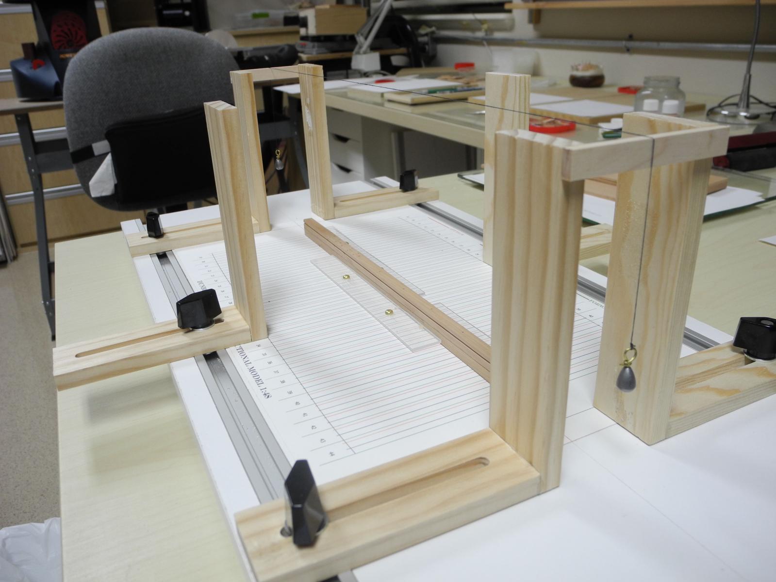
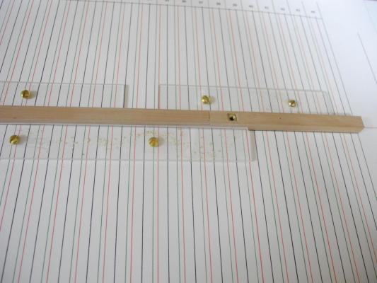
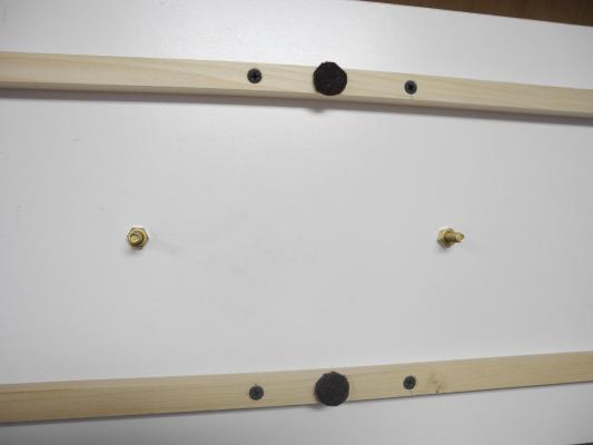
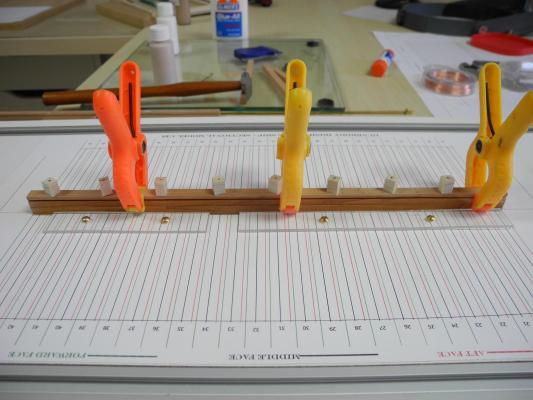
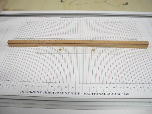
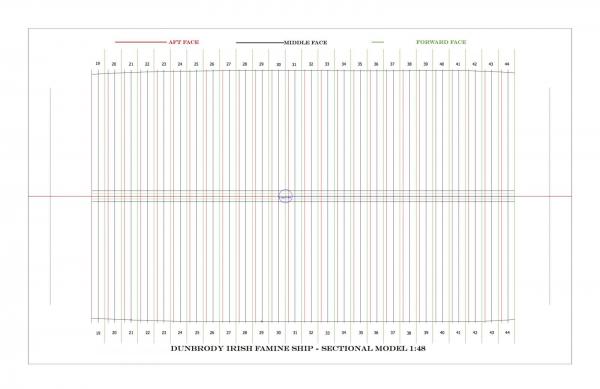
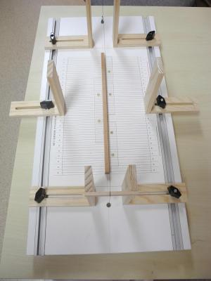
Part 3 – The Model Shipway Before beginning construction on the model, I needed to build the platform to support the ship during construction – the Model Shipway. I used a 12x24 melamine shelf for the building board, mounted some 5/8x5/8 rails under it, and added felt feet to save the surfaces it would be on. A centerline was scribed down the center of the Shipway. This shelf is only 21/32 thick, so it is not thick enough to support the normal ½” T-track. I was able to find shallow T-Track (3/8”) from Lee Valley, along with T-Nuts specifically configured for these tracks. A scaled drawing of the frame configuration of the sectional model was needed for the Shipway. I developed this using TurboCad Designer (a 2D CAD program). There will be 52 frames in the sectional model, arranged in frame pairs or framesets. The 26 framesets of the sectional model are represented by the different color lines. The green line is the forward face of the forward frame of a frameset. The red line is the aft face of the aft frame of a frameset. The black line is the junction of the two frames, or the middle of the frameset. It can be seen that the frames are very close to each other – not the usual ‘room and space’ that we would normally expect. The sided dimension of the floor of each frame in a frameset is 8.5 inches, making the frameset 17 inches at the floors. The space between frames is only 5+ inches, or 0.11 inches at 1:48 scale. The drawing of the frame configuration was printed on 11x17 card stock (I found 100 lb card stock that my printer was able to handle). After it was trimmed to the appropriate size, 9x15.5, I aligned the centerline of the drawing with the centerline of the Shipway, then glued it to the Shipway using Krylon 7010 spray adhesive. I coated the drawing with Krylon Preserve-it to protect the drawing (I learned of these products from Ed’s Young America book, and they’re excellent). I constructed two types of fixtures for the Shipway, as shown in the following photo (the keel is already installed in this photo, but more on that in a later post) The fixture in the middle of the Shipway will be used to align the individual frameset during installation, and will also serve as a clamping base to secure the frameset while the glue is curing. The gantry-like fixtures at each end will be used to hold a string stretched between them as an aid in centering the frameset. These strings are laid in notches in the cross-piece and have been centered over the centerline of the drawing. The centering string and its weights can be seen in this view of the Shipway. The next post will address making the keel and mounting it to the Shipway.

- 649 replies
-
- 24
-
-
- dunbrody
- famine ship
- (and 2 more)
-
Hi Bob, Mark, and Patrick - welcome aboard! I hope you enjoy the build. Hi Richard - thanks much for the link. I think it will be a useful resource.
- 649 replies
-
- 4
-
-
- dunbrody
- famine ship
- (and 2 more)
-
Thanks Ed and Nigel. I welcome any comments or suggestions you care to make along the way.
- 649 replies
-
- 5
-
-
- dunbrody
- famine ship
- (and 2 more)
-
Hi Patrick - just tried sending you a PM but I think your mailbox is full. Wanted you to know I finally started the build log for Dunbrody in the Scratch section. I'm enjoying all of your builds and hope you enjoy watching my latest (it's a challenge!) Frank
-
Hi Greg and Patrick A meter is 39.37 inches, so a 37 meter yacht should be 1457 inches (121.4 ft). 1457 Inches at 1:200 scale would be 7.285 inches, so Patrick is right (why am I not surprised?). (I learned inches to a meter back in basic training eons ago - never forgot it, but this is probably the first time I've ever used it!)
-
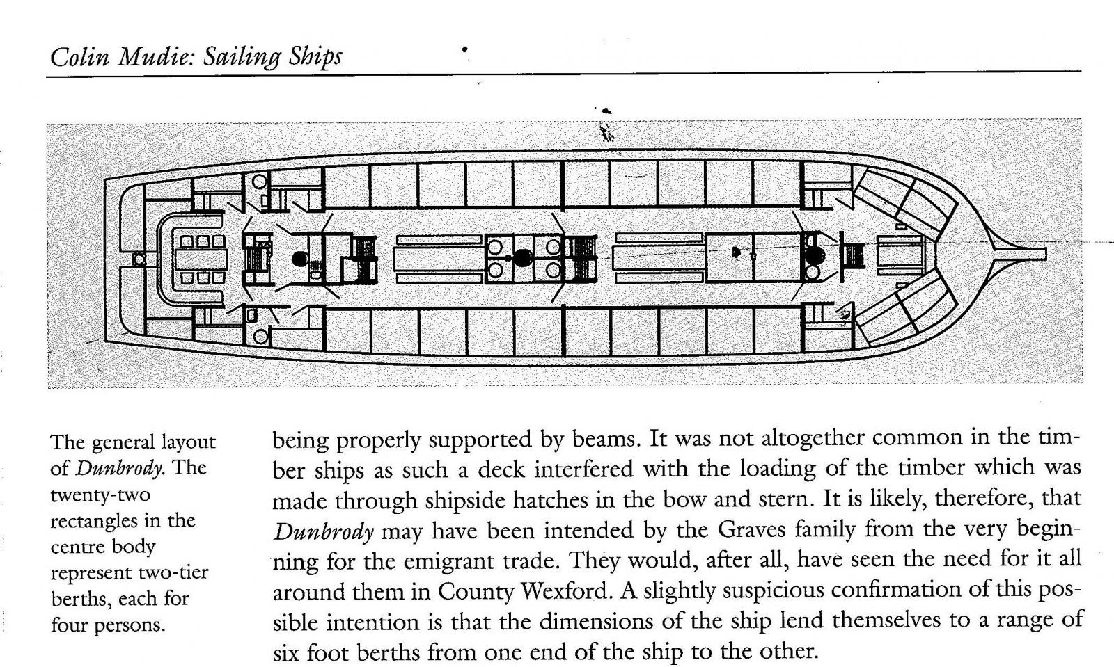
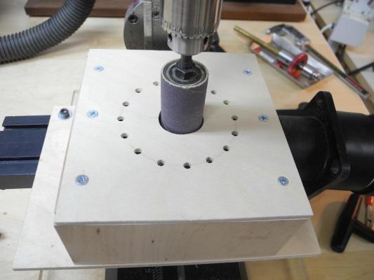
Part 2 – The Sectional Model My interest in the model is to show the portion of the ship that was occupied by the Irish emigrants. The Accommodation Deck consisted of three main sections: the aft section contained the quarters for the ship’s officers and first class passengers, and the forward section was the quarters for the ship’s crew. Temporary quarters for the emigrants were set up in the central area of the ship. The following illustration from Colin Mudie’s book depicts the general layout of the Accomodation Deck. His comments are interesting, in that he suspects the ship was designed from the beginning to support the emigrant trade. The sectional model will encompass the central area of the ship, from frame 19 to frame 44, a distance of 48 feet. This area is the middle of the emigrant area. The scale will be 1:48, so the model will be 12 inches long. The starboard side of the model will be completely built, but the port side will be left as open as possible so that the interior of the ship showing the emigrants living conditions can be seen. On a trip to Ireland in 2013 I toured the Dunbrody, and was taken by the cramped quarters the emigrants shared during the voyage. Structural timbers will be made from Madrone, a hardwood from the Pacific Northwest that is very similar to Pear in that it is relatively dense, has a very tight grain, and is a light pinkish-brown color. Madrone machines very cleanly, and finishes well. Madrone is sometimes difficult to find, but is much less costly that European pear woods. Planking, deck furniture, and other non-structural parts will be made from Castello, which has many of the same properties and color as Boxwood. I haven’t decided yet whether the model will be presented on a simple base or whether I will build a model of the building slip for the ship. I am also considering using some figures of emigrants in the ship, but this depends on being able to find 1:48 figures that can be used with some minor modifications.
- 649 replies
-
- 11
-
-
- dunbrody
- famine ship
- (and 2 more)
-
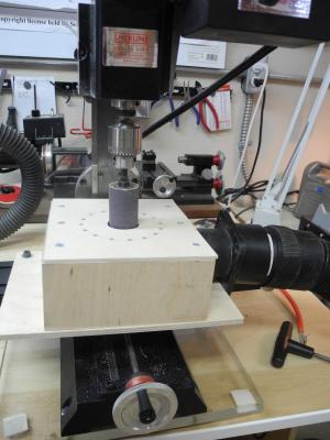
Part 1 - Introduction When I first started ship modeling in 2012, I purchased a set of plans from Seaways Publishing for the Dunbrody Irish Famine Ship. The plans appealed to me because I was born in Ireland and have read quite a bit on the famine years. The Dunbrody is a replica of an actual ship that was built in Quebec in 1845 by Thomas Hamilton Oliver for William Graves, a lumber merchant from New Ross in County Wexford in the southeastern part of Ireland. The Dunbrody’s construction coincided with the Irish Famine years, during which the Irish tenant farmers were starving due to the failure of their potato crops – their primary food source. The ship was designed to carry lumber from the new world to Ireland and England. On her return voyage she mainly carried pig iron and limestone, which left room for carrying a fairly large number of passengers and normally accommodated up to 176 Irish emigrants who were trying to escape the potato famine. The replica ship was commissioned by the John F. Kennedy Trust of New Ross, as a tribute to the emigration of the Kennedy family from their Irish homestead near New Ross. The current Dunbrody was designed by the naval architect Colin Mudie, who had designed a number of replica ships. The plans for the replica were based on entries for the original ship in the Lloyd’s Register, and from certificates and surveys. Mr. Mudie also wrote a book titled “Sailing Ships” in which he presented a number of ships he had designed. The book included a section on the design and construction of the Dunbrody. I don’t think I had any real thoughts on how to model the Dunbrody when I originally purchased the plans. I was new to modeling and didn’t have any experience in scratch building. After seeing Ed Tosti’s work on Young America I decided a few things. First, Dunbrody is not a very refined ship, and her lines are no comparison to the beauty of the clipper ships. My primary reason for building Dunbrody is to show the accommodations for the Irish emigrants. I felt that this could best be accomplished by building a sectional model. The plans from Seaways Publishing contain most, if not all, of the details needed to construct an accurate model, so I would try to reproduce the details presented in the plans. I would use Ed Tosti’s build logs and books for Naiad and Young America to learn the techniques and processes I would need to build the model. In addition to the plans for Dunbrody, and Ed’s books, I will also be using two excellent books as references: “American Built Packets and Freighters of the 1850s” by William L. Crothers and “Wooden Ship-Building” by Charles Desmond. A number of questions arose as I started planning for this build, and I started a thread entitled “Planning for a Sectional Model of Dunbrody” to get some feedback from the more experienced modelers on this site. Most of my questions have been resolved, so it’s a good time to start building.

- 649 replies
-
- 15
-
-
- dunbrody
- famine ship
- (and 2 more)
-
Looking good, Mark. Can't wait to see it in person at the next club meeting.
-
Hi Patrick I'm doing much better since the operation in the fall - thanks for the kind wishes. I'm now back to 'normal' and have started real work on the next project after spending some time doing the planning. I hope to start a build log in the next week or so.
-
That's quite a marina Patrick. I'm continually amazed at the scale you're able to work in. Every time your thumb sneaks into a photo it reminds me of how small your models are. The work is so fine that they appear bigger when alone in a photo. Great work!
-
Incredible detail Ed, this will be a very complete model.
- 3,618 replies
-
- 5
-
-
- young america
- clipper
- (and 1 more)
-
Ed, the precision of your work continues to amaze me.
- 3,618 replies
-
- 6
-
-
- young america
- clipper
- (and 1 more)
-
No magnification!?!? Wow, now I'm doubly impressed. I need to resort to the Optivisor for items that tiny. Bravo!
-
Looks great Patrick - just a little touch-up here and there. What strength magnification do you use when working on it?
-
Sorry I'm very late to the party. Wonderful work and excellent explanations - thanks for sharing this!
- 641 replies
-
- 3
-
-
- greenwich hospital
- barge
- (and 1 more)
-
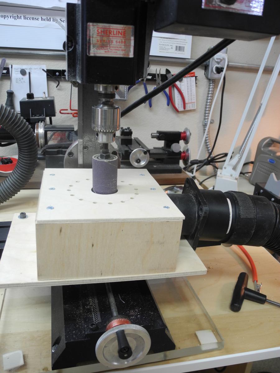
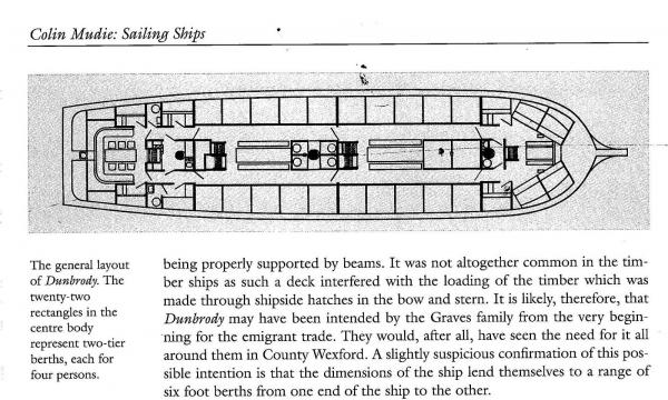
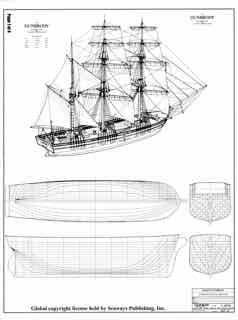
I've been learning to make my own frames, which require sanding on the inside curve. I have some sanding drums for my drill press, but they cause a lot of vibrations due to the way the sandpaper is mounted on the drums. I have some 1 inch sanding drums that can be used on a Foredom tool and which take sanding sleeves rather than sandpaper sheets, so I decided to try using these on my milling machine rather than the drill press. I made a smaller version of the dust-collecting box that I use on the drill press, and set it up so that it would clamp on the x table of the mill using cap screws and t-nuts. The variable speed on the mill is very useful in getting the right speed. I suppose it's not quite as good as a real spindle sander, but it cost nothing to make (I already had the required parts and wood) and serves my purposes well.
- 146 replies
-
- 11
-
-
TurboCAD PC vs Mac
Mahuna replied to Maury S's topic in CAD and 3D Modelling/Drafting Plans with Software
I use TurboCad Designer (2D only version) on the Mac, and have had no issues with it. I'm a relatively new CAD user, so I can't make any real comparisons.