Mahuna
-
Posts
1,504 -
Joined
-
Last visited
Content Type
Profiles
Forums
Gallery
Events
Everything posted by Mahuna
-
 Thanks Druxey. The flex I'm concerned with is lateral, due I think to the height of the keel and false keel, so I don't think the keelsons or any other longitudinal timbers will reduce that. I'm concerned this might be a problem when I start fairing the inside of the frames. I'm thinking of adding some supports on the shipway under the turn of the bilge to form a sort of cradle for the hull so that it doesn't rock side to side.
- 649 replies
-
- 4
-

-
- dunbrody
- famine ship
- (and 2 more)
-
Thanks Patrick. Lots of challenges already, but I'm learning a lot from this build. Hi Brian - they have lots of nice tools. Every time I look I discover something else I 'need'.
- 649 replies
-
- 4
-
-
- dunbrody
- famine ship
- (and 2 more)
-
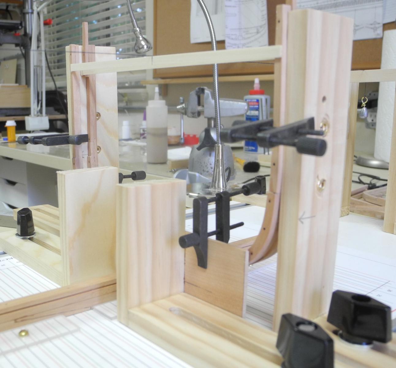
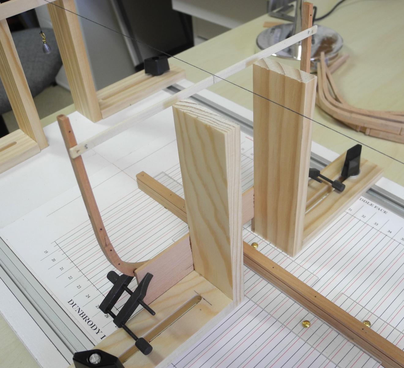
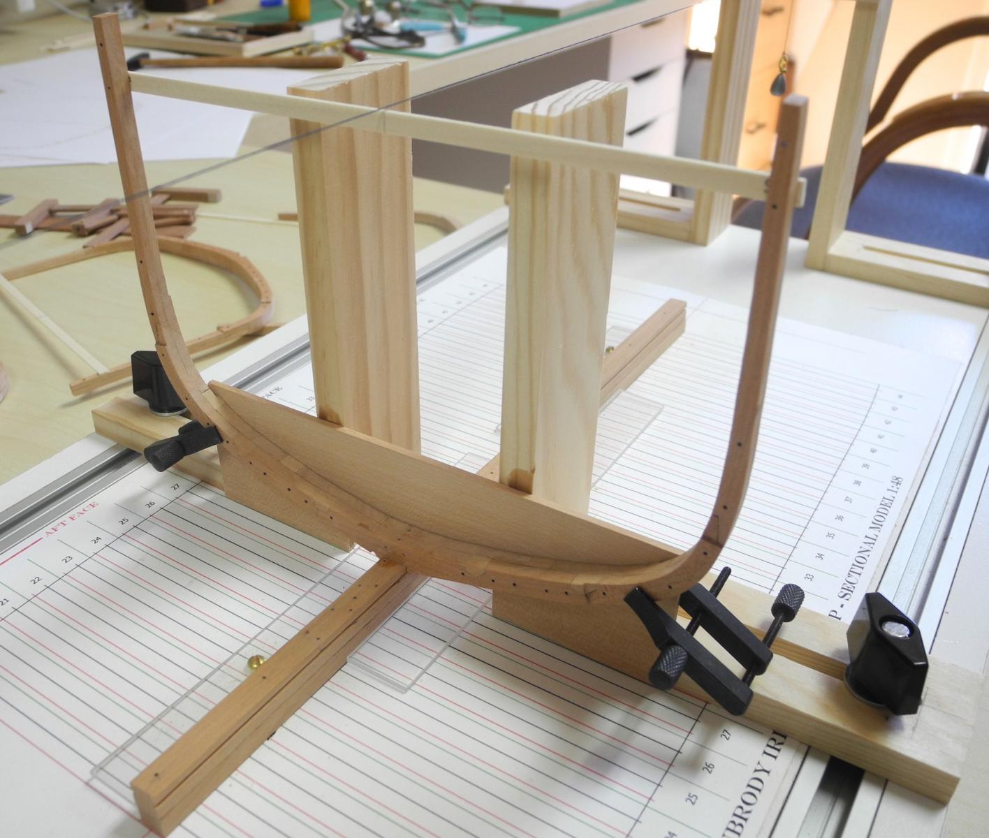
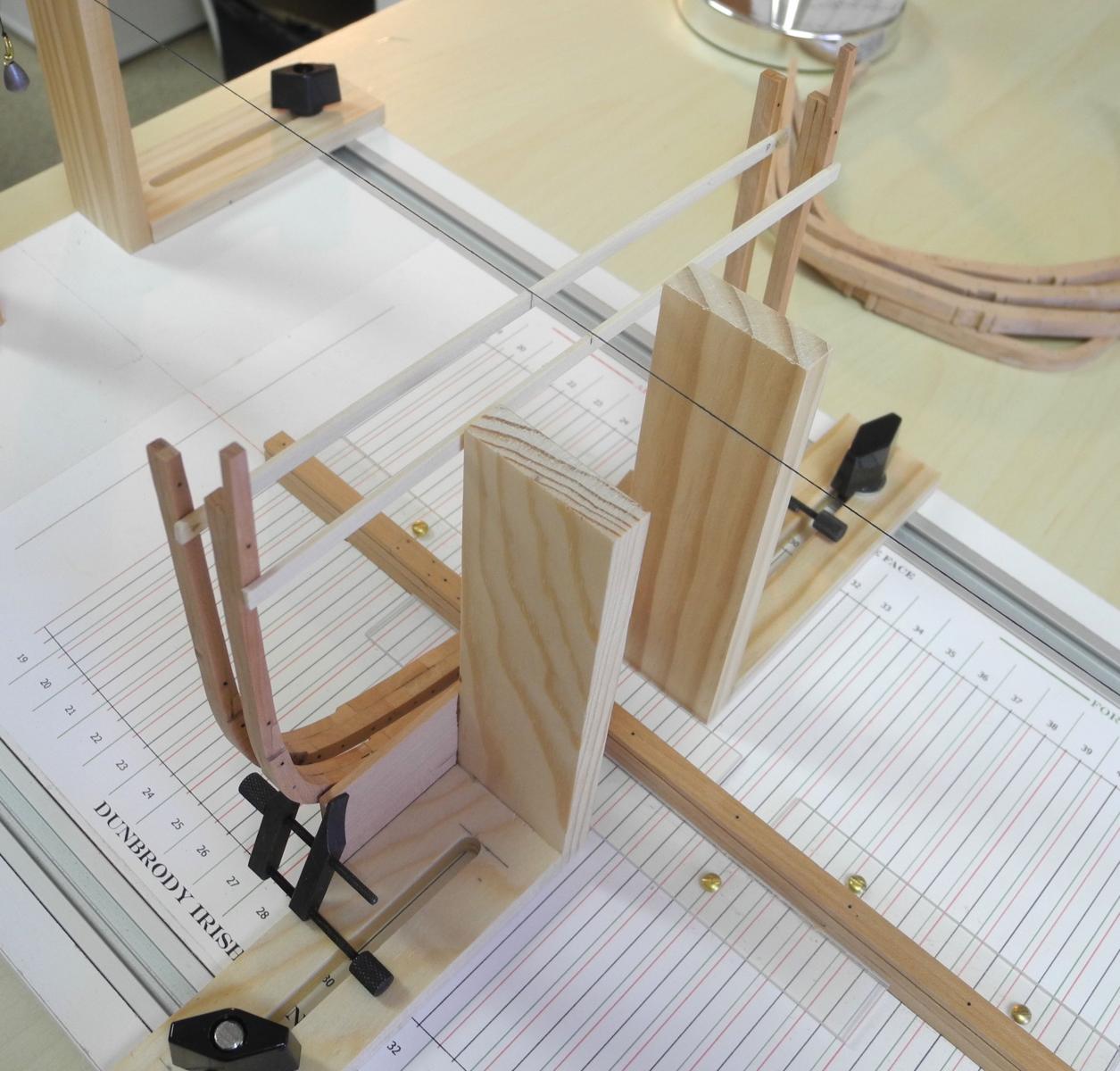
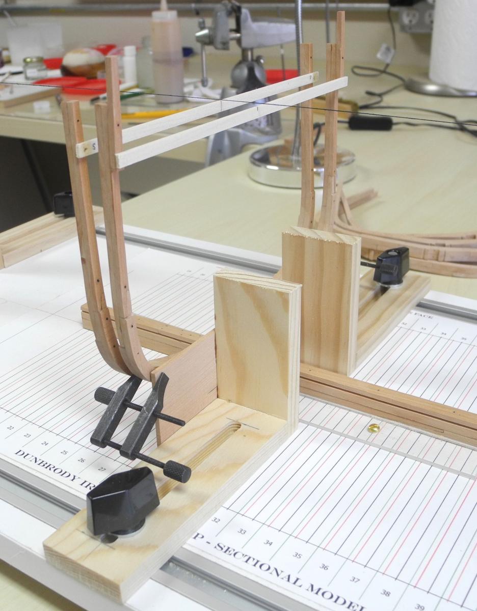
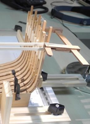
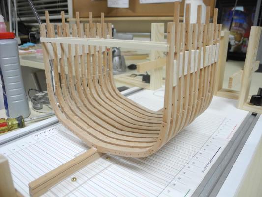
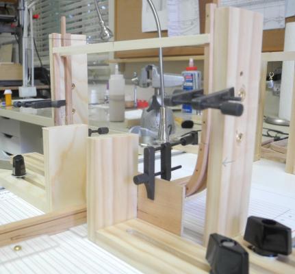
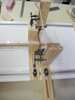
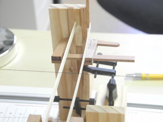
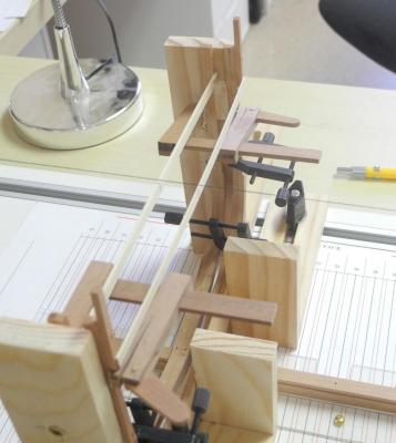
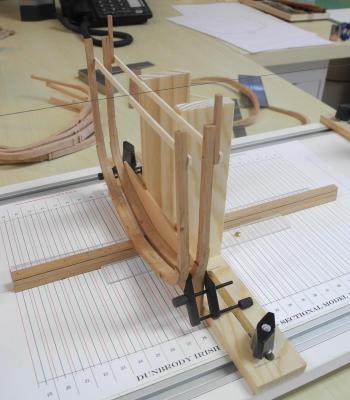
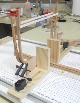
Part 12 – Installing the Frames – cont’d I was able to get a lot of work done this weekend. I had already constructed the middle 11 frames – frames 27 – 37. These are the frames that are identical, so it made things go fairly quickly. As I was installing the frames, I started to notice that some of the frames were not lining up laterally, even though I’m using cross-spalls for centering the frames. I decided to add a fixture that would keep the frames in line – essentially a straight wooden bar that will press against each side to keep the frames in line. This also strengthens the entire assembly when I need to adjust the frame being installed. Without this fixture the keel seems to flex, causing all of the frames to move, not just the one being adjusted. This fixture seems to solve that issue also. The cam clamps are coming in very handy. I use a machinist’s square to check the vertical alignment of the frame being installed. Then I prepare a filler block to the correct size for maintaining that alignment. When the filler block is glued in I use the cam clamp to gently keep the frame in place. (I needed to reduce the depth of one of the jaws so that it would fit between the frames – but this is one of the benefits of making your own clamps, they’re easily modified. So we now have 11 frames mounted. 3 more are ready or in the final stages of construction. After that I’m afraid things will slow down, since it takes the equivalent of a 6-hour day to prepare one frame. With 15 still to go I estimate another 3 weeks before I can move on to the next work. I'll post progress reports periodically. Thanks for following along.
- 649 replies
-
- 20
-
-
- dunbrody
- famine ship
- (and 2 more)
-
Hi Mark - we missed you today, and we would have enjoyed seeing the current state of your ship. Hope you can make the next meeting - 5/21.
- 71 replies
-
- 1
-
-
- cutty sark
- mantua
- (and 2 more)
-
I continue to be amazed at the level of detail you're able to put in such a tiny space. Great work!
-
Thanks Druxey. The clamps are especially useful to hold something in place with minimal pressure. Thanks Elijah. Fixing is always part of it (for me, anyway)
- 649 replies
-
- 4
-
-
- dunbrody
- famine ship
- (and 2 more)
-
Thanks Alan. I agree that taller supports would normally be better, but the sided dimension decreases at the higher points of the frame, so that wouldn't work. Similarly, there is only a small part of the frame that is at maximum width, so clamping to the new fixture needs to be at the correct location. This has been a real learning experience for me, and I'm happy if this log helps others as well.
- 649 replies
-
- 3
-
-
- dunbrody
- famine ship
- (and 2 more)
-
Yes, Brian - the filler pieces are temporary. I'll probably remove the spalls fairly early in the process, but the fillers will remain until I get ribbands installed.
- 649 replies
-
- 4
-
-
- dunbrody
- famine ship
- (and 2 more)
-
Very elegant - and I'm very impressed by the tiller! If you can do that by hand I guess you don't need a lathe.
- 641 replies
-
- 5
-
-
- greenwich hospital
- barge
- (and 1 more)
-
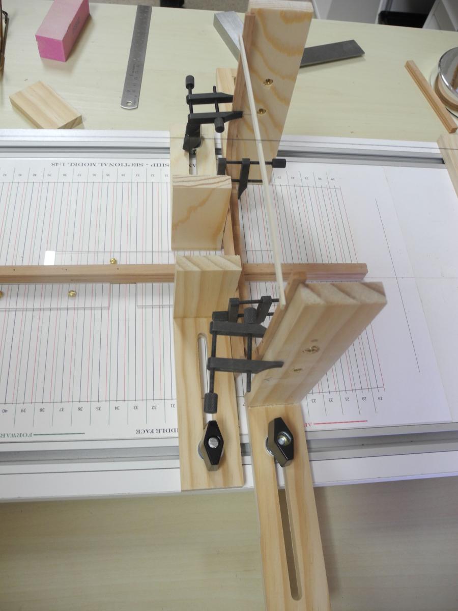
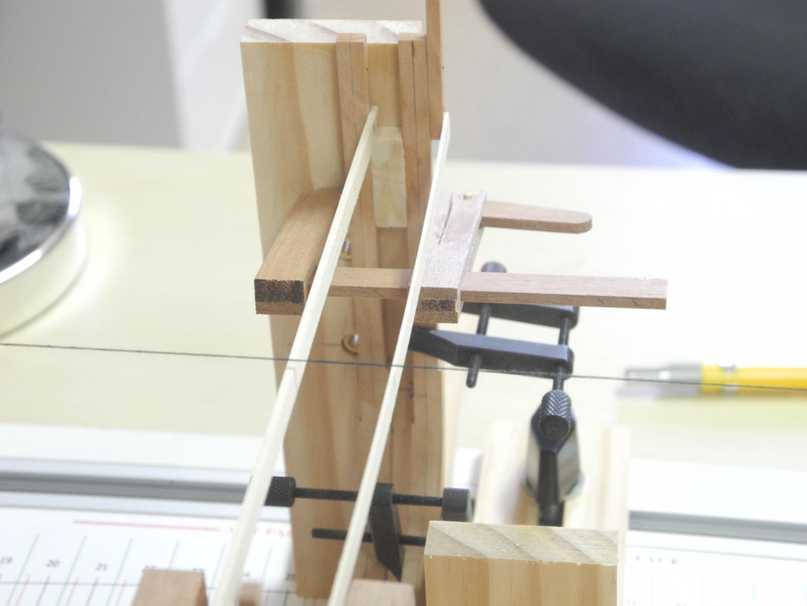
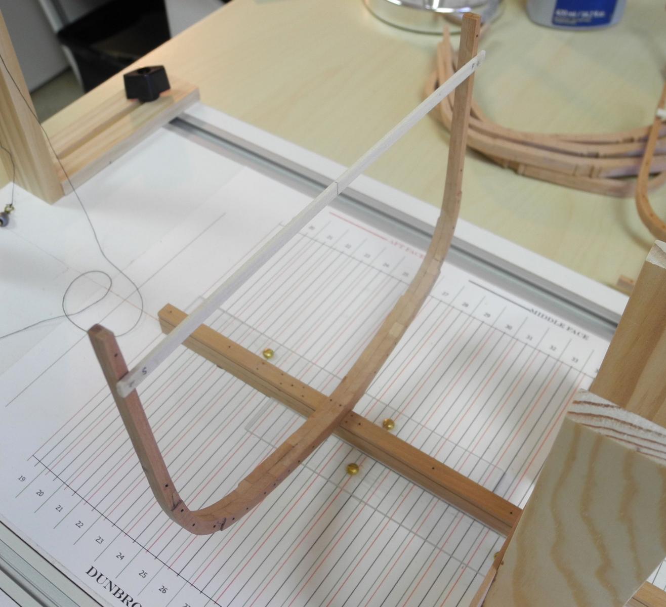
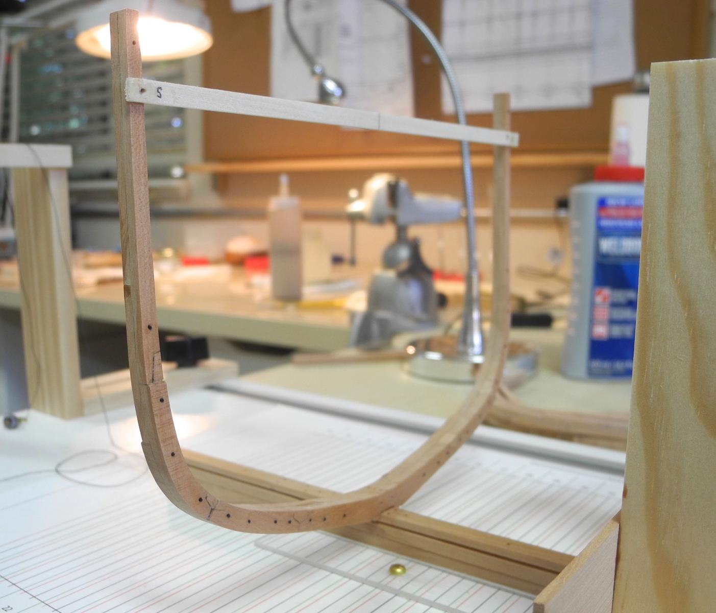
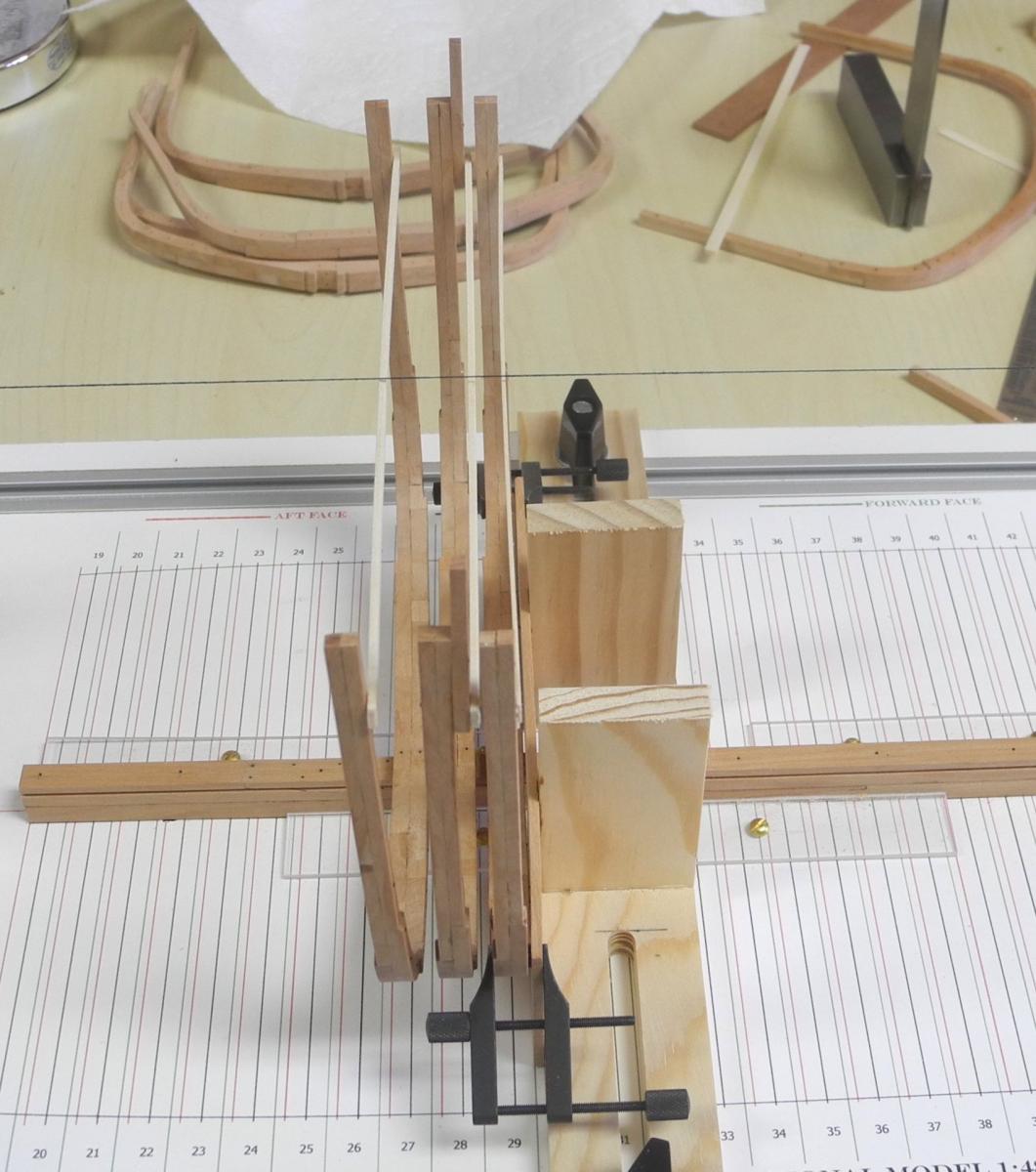
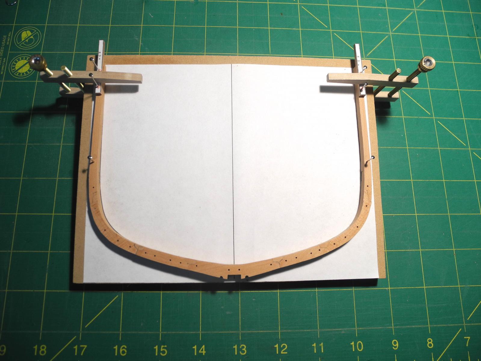
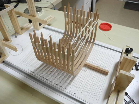
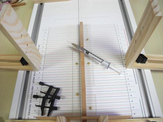
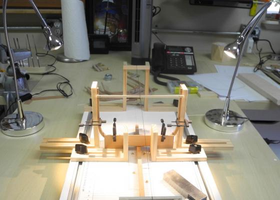
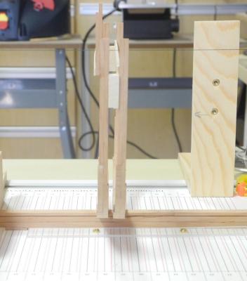
Part 11 – Installing the Frames – cont’d Well, I looked closely at the frames and checked them out with a square. Unfortunately, Brian was correct – frame 27 leaned badly aft, and frame 29 leaned forward. Frame 28 wasn’t too bad, but I decided to remove all three frames and start over. I injected isopropyl into the mounting holes in the center of each frame, and brushed some hot water on them as well. They all came out fairly easily. I decided to use another fixture (one on each side) that would allow me to keep the frame positioned vertically perpendicular to the shipway. The edge of the fixture is lined up with the joint line between the two sister frames (sorry about the out-of focus photo). A key in being able to see the joint is to have enough light! I have a couple of small lamps from Ikea that I find extremely useful, and I positioned these on each side of the frame – worked great! I dry-fit a frame using the new clamping arrangement and it worked fine. So I went ahead and installed frome 27, followed a few hours later by 28. When everything was clamped well, I then installed filler pieces between the frames. These fillers, as in the spalls, are of poplar. The cam clamps are homemade clamps from an article in an old magazine on miniature woodworking - they're a miniaturized version of a luthier's clamp. After a couple of hours to set, I removed the clamps and the frames look good – and they check out with a square as vertical. Another lesson learned, and another step along the way.

- 649 replies
-
- 19
-
-
- dunbrody
- famine ship
- (and 2 more)
-
Hi Bob: In Post #55 I changed the plan from pinning the spalls to glueing them. Since the face is already finished with Poly, they come off very easily (sometimes too easily!).
- 649 replies
-
- 3
-
-
- dunbrody
- famine ship
- (and 2 more)
-
Hi Brian: I saw the same thing, and decided to leave it overnight before checking where the issue might be. I'm inclined to think it's the middle frame of the the three, but won't know until I get a square on the frames to check them out. I also noticed that when centering the frame being added, it sometimes causes the already installed frames to move left and/or right - probably due to slight flexing of the keel assembly. This tells me that the notch in the frames needs to be widened slightly. I had made them pretty snug to ensure that the frame stays centered on the keel, but this doesn't give me much leeway for adjusting the frame. I think the answer may be that the notch needs to flare out slightly at the bottom - this would allow me to slightly rock the frame while staying centered on the keel. I'll be adding filler pieces between the frames today, and I hope I can use them to fix any alignment issues. I'll also be adding a fixture to stabilize the frames already installed so that any movement in a new frame won't affect the rest of the hull. This is continuing to be a real learning experience.
- 649 replies
-
- 6
-
-
- dunbrody
- famine ship
- (and 2 more)
-
Thanks Patrick. You're right - it's always great to see progress in our work.
- 649 replies
-
- 4
-
-
- dunbrody
- famine ship
- (and 2 more)
-
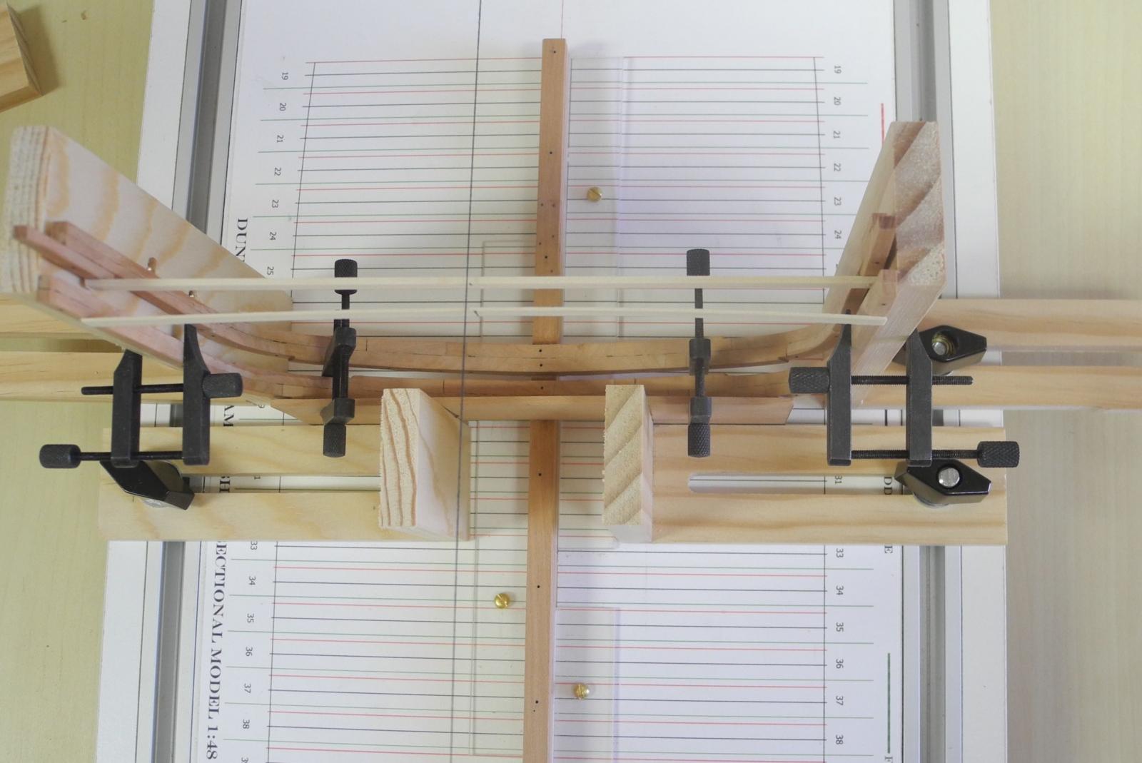
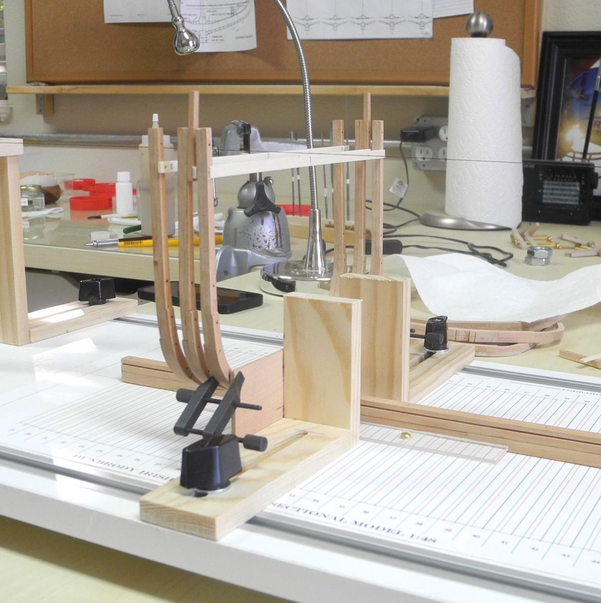
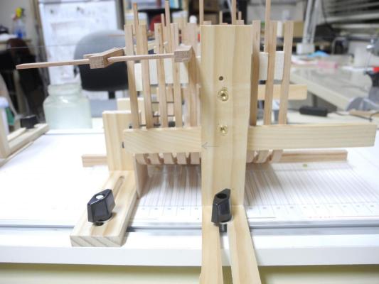
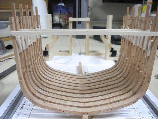
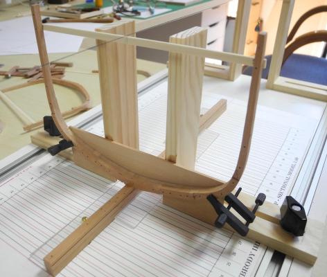
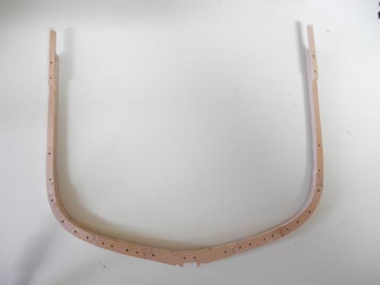
Part 10 – Installing the Frames The frames of the sectional model are numbered 19 through 44, with 19 being the aftmost frame of the model. Frames 27 through 37 are identical, and these are the frames I made first (almost all are completed). Installation of the frames will start with Frame 27 and go forward. 19 through 26 will be finished later. Well, I reached a milestone today – I started installing the frames! I am using cross-spalls on each frame for centering, and as suggested earlier will leave them in place until the hull becomes more secure via the installation of ribbands. The installation of the frames will be as discussed earlier – clamping the frame to the framing fixture that is located at the line indicating the forward edge of the frame. Here’s the first frame in place: After about 4 hours of drying time I removed the fixture and left the frame standing by itself. I was very pleased with my first frame. Now for a few more. The next frame, being an even-numbered frame, has bulwark stanchions on the forward face. I immediately noticed that the spall on this new frame almost touched the uprights of the framing fixture. So before glueing this frame in place I removed the fixture and reduced the height of the uprights – they don’t serve any purpose other than to hold the flat board that is used for alignment. After this second frame was glued and allowed to dry (again about 4 hours) I installed the third frame and learned another lesson! Some of the spalls I’m using are 1/16 thick, and some of them are 1/32 (this is stock I had milled a while back, thinking I would use them for a build that has been postponed). I wasn’t paying too much attention to the thickness I was using for each frame. The spall I used on the frame with the stanchions is 1/16 thick, and this brought the spall very far forward, almost touching the frame in front of it. So from now on I’ll be using the 1/16 spalls on the odd-numbered frames, and the 1/32 spalls on the even-numbered frames with stanchions. These were good lessons, and fortunately no harm was done. The next task is to determine how to make appropriate sized filler blocks that I can temporarily install between the frames for added strength. Then I’ll continue with the installation. So going forward I’ll be alternating between making frames and installing them. At this point I have 3 frames installed, another 8 almost ready for installation, and 15 more waiting to be built and installed. The remaining 15 frames will also require some drafting for each one, so that might slow things down a little. Thanks, everyone!


- 649 replies
-
- 17
-
-
- dunbrody
- famine ship
- (and 2 more)
-
Thanks Druxey. Yes - my shop is well-ventilated and I use the acetone in front of an open window.
- 649 replies
-
- 4
-
-
- dunbrody
- famine ship
- (and 2 more)
-
ok Brian - we'll see how acceptable when I start erecting the frames. Hopefully I'll have a few in place by Saturday. See you then.
- 649 replies
-
- 4
-
-
- dunbrody
- famine ship
- (and 2 more)
-
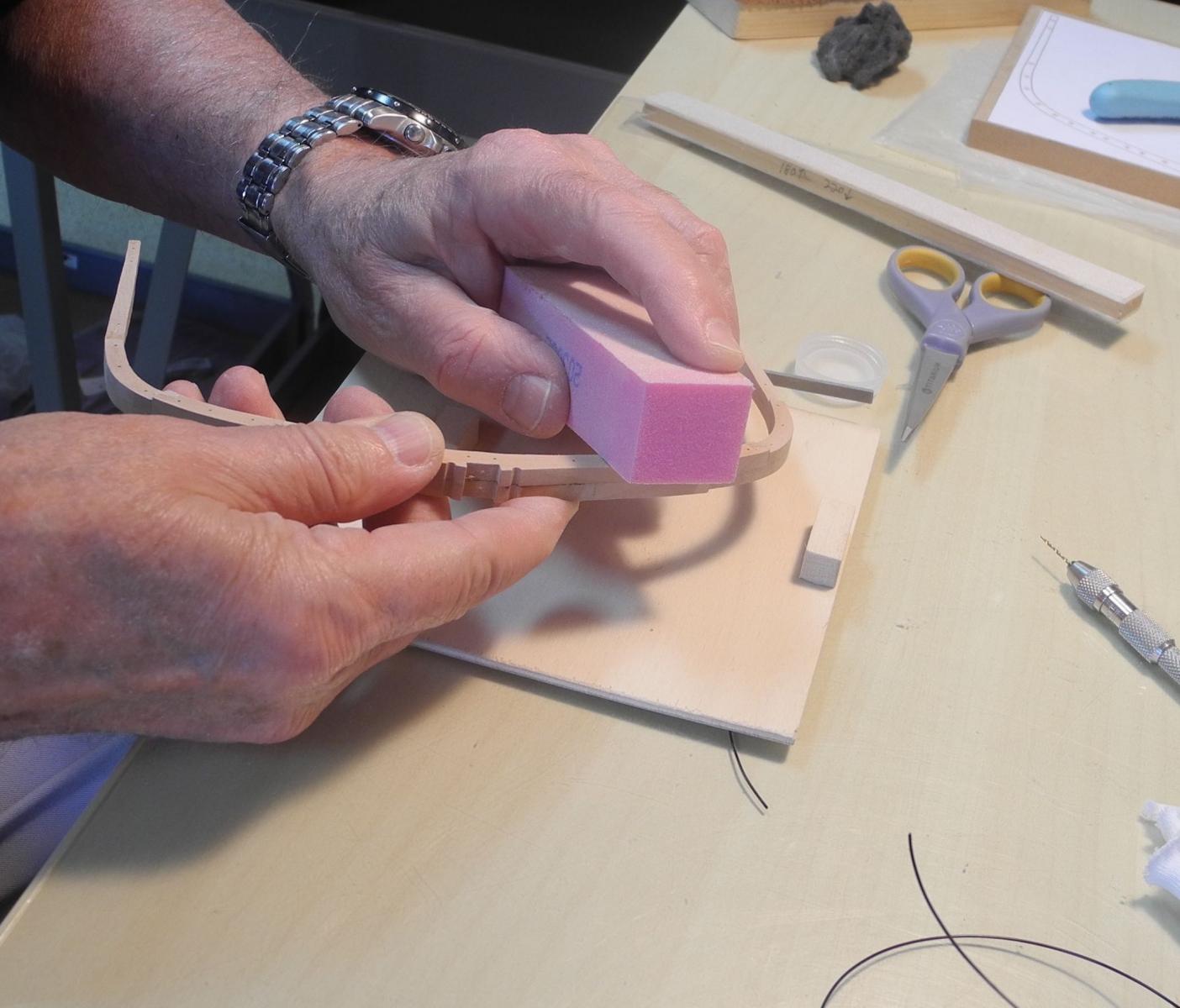
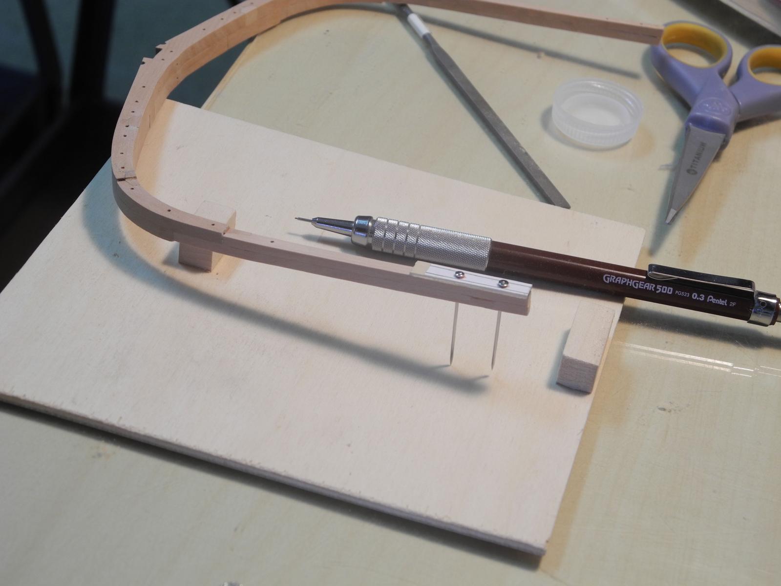
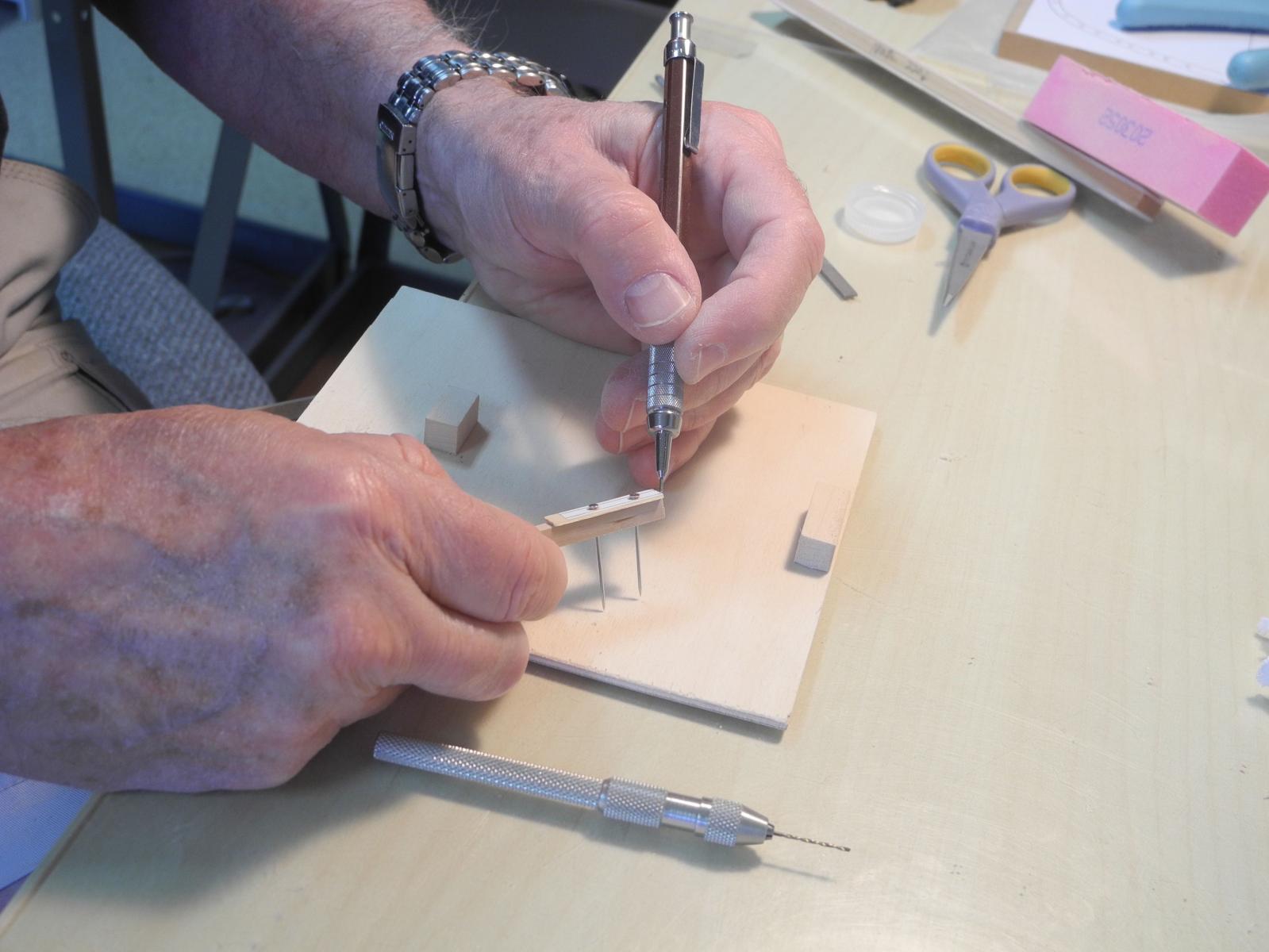
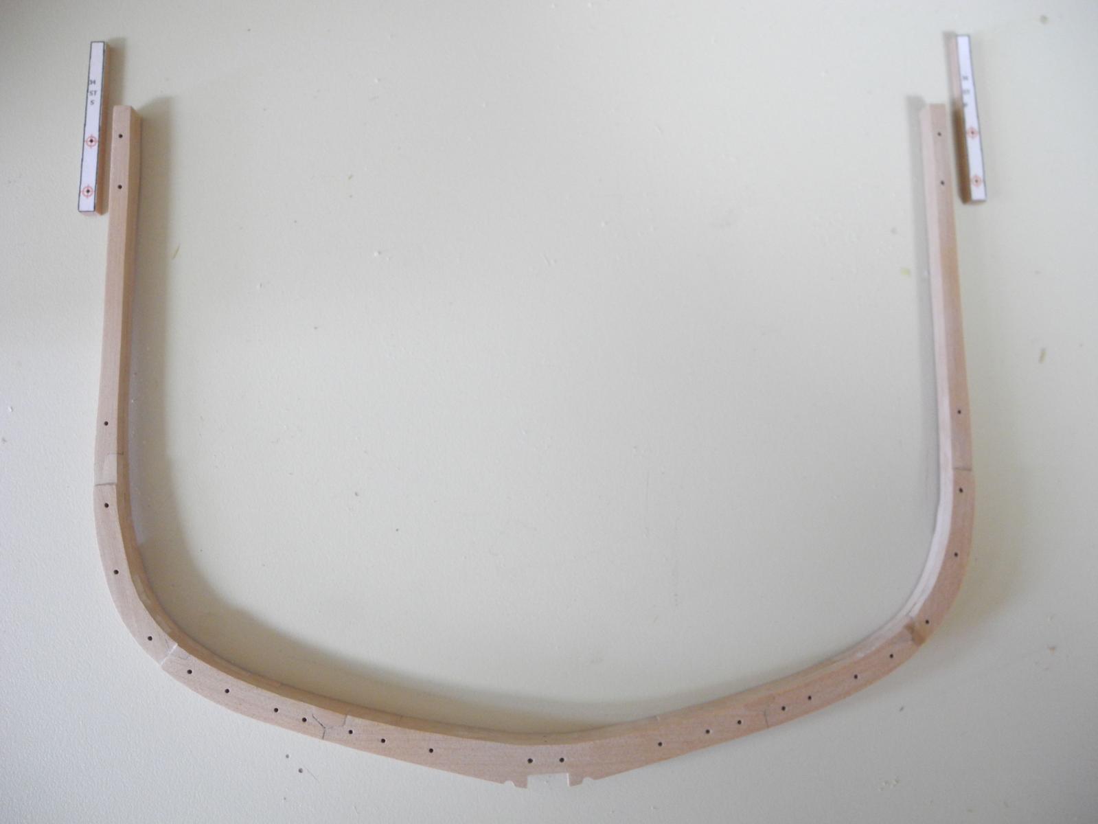
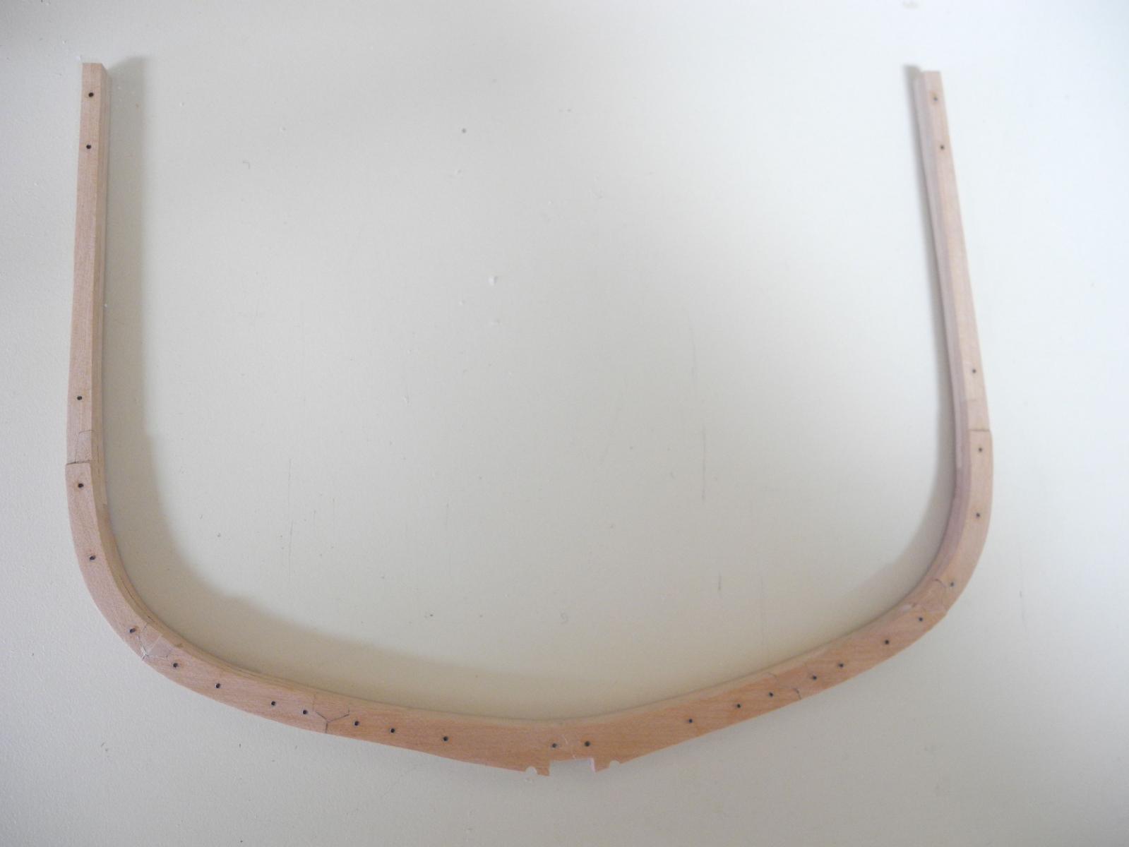
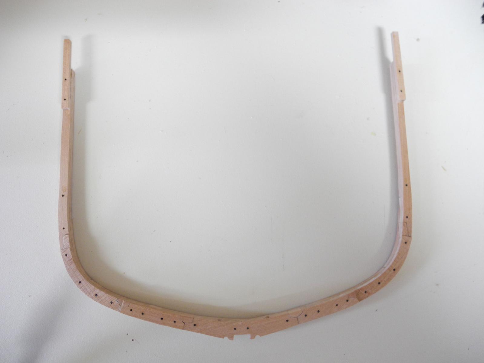
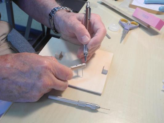
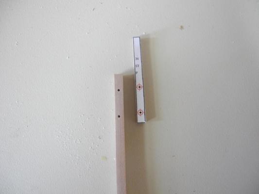
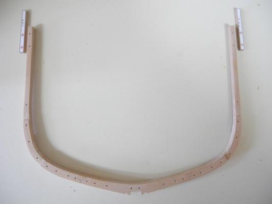
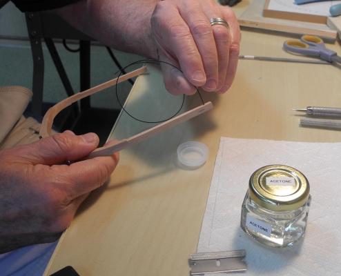
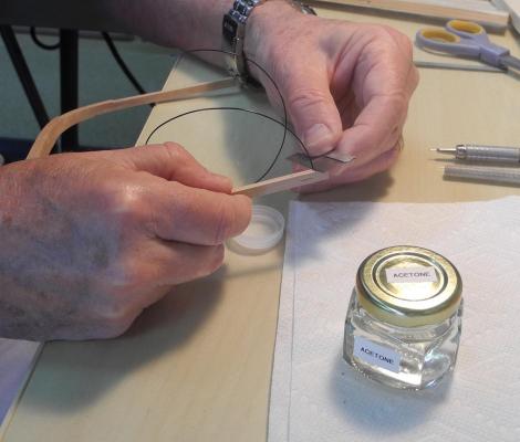
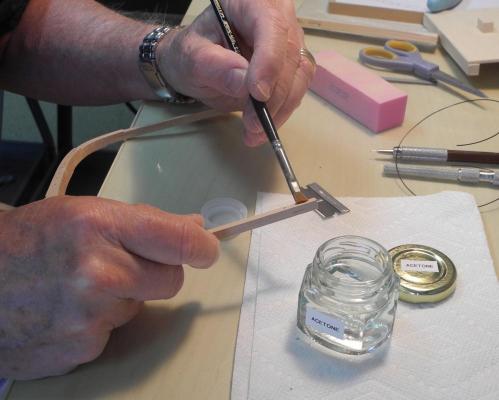
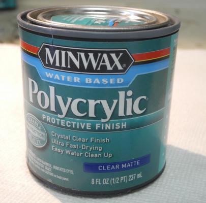
Part 9 – Finishing the Frames Although the actual construction of the frame is completed, there are still a few things that need to be done before the frame can be erected on the keel. The glueing of the two frames together and the wetting of the frames will have caused some of the holes to be clogged with glue, or for the wood to have swollen and caused them to close. A drill bit in a pin vise is used to open the holes back up. Also, the wetting of the frame to remove the paper and glue will have raised the grain, causing the surface to appear rough. The frames are re-sanded with a 220 grit sanding stick, and then a buffing pad used for manicures is used to ‘polish’ the frames. The height of the frame was not finished sanded, since two frames would be sistered and the height of the two frames together should be consistent. I made a small ‘gauge’ for marking the final height of the frames. This is simply the top of the frame drawing glued to a small piece of hardwood and sanded to the proper line. This gauge is pinned to both port and starboard sides of the frameset, and a pencil line is marked on the frameset. The frameset is then sanded to these lines for the final height. Every even-numbered frame needs two bulwark stanchions added. These are made as separate drawings and glued to a piece of 7/64 stock. The stanchions are then pinned and glued to the frameset. The holes that were used for pinning are placed in the locations where bolts would have been used to secure all of the frame components. To simulate these bolts I used 40 pound test black monofilament. The ‘bolt’ is dipped in medium viscosity CA glue and inserted into the hole. Then a razor blade is used to trim the monofilament flush with the face of the frame. Acetone is applied with a ‘scrub brush’ to remove any CA that stayed on the surface. (The ‘scrub brush’ is actually an old artist’s brush with the fibers cut back to make a short stiff brush.) The fore and aft faces of the frameset need to be finished, since there won’t be enough room after installation to reach these faces. I decided to use a water-based poly product from Minwax called Polycrylic. The one I chose gives a clear matte finish. On my previous build I experimented with several different finishes and found that this product preserves the color of the madrone while the others darkened it considerably. I also like the fact that it’s a brush-on finish and it’s easy to clean up with water. The preparation of the frames is completed Now it’s time to start installing the frames on the keel, which will be the subject of the next post. Again, thanks everyone for the ‘likes’ and for following this build.


- 649 replies
-
- 21
-
-
- dunbrody
- famine ship
- (and 2 more)
-
Thanks, Patrick. Yeah, there are 52 individual frames in 26 framesets - that's 572 fiddly pieces just for the frames, and I'm only building the middle part of the ship! But I'm actually enjoying it.
- 649 replies
-
- 5
-
-
- dunbrody
- famine ship
- (and 2 more)
-
Welcome back, Brian! I've been waiting for this to start.
-
Hi Patrick - took your advice and am having a glass while admiring your yacht. Spectacular - another one of a kind build out of your shipyard.
-
Thanks Brian - everything about this hobby is fun (most of the time). Looking forward to hearing about your sailing adventure.
- 649 replies
-
- 4
-
-
- dunbrody
- famine ship
- (and 2 more)