


realworkingsailor
-
Posts
3,082 -
Joined
-
Last visited
Reputation Activity
-

 realworkingsailor got a reaction from catopower in Was the working shipyard dock's bottom flat or sloped? (18th century)
It’s important to distinguish the difference between a build ways and a drydock. A build way is typically sloped to the water’s edge, and while the ship is built, it doesn’t actually rest on the slipway until just before launching.
A drydock is constructed below the level of the water, and does have a flat bottom. It might have some sloped drainage towards the centerline, or to wherever the drain valves are located. Where pumps are not available, drydocks can make use of natural topography to fill and empty. For example, by locating the dock some ways up a river, after closing the gate, the water can be drained to sea level (helps also to do the draining when the sea is at low tide). There is a drydock in Port Weller, Ontario, that is located above the first lock in the Welland canal. It doesn’t use pumps at all. The water is allowed to drain down the 40’ drop into Lake Ontario.
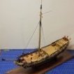
Things haven’t changed too drastically over time so some pre-modern ship launching techniques are similar. Prior to launching, the slipways (usually a pair of flat beams laid astride the keel (you can see these in the picture of the shipyard model you posted), are well greased with tallow or other lubricants. A pair of special launch cradles are constructed fore and aft. These cradles will bear the weight and balance of the ship when it comes time for the launching. These will slide down the slipway, but are held static by a series of chocks and braces. Once the launch cradles are built and braced in position, the ship is then slowly lowered from its build staging (usually by knocking out the keel blocks) onto to the launch cradles. Any remaining staging is removed, and when the time comes for launching, the chocks are knocked out and the cradles (with the ship) slide down the ways into the water. Typically hawsers or anchor cables are used to arrest the movement of the ship once waterborne.
Hope that helps.
Andy
-
 realworkingsailor got a reaction from davyboy in Was the working shipyard dock's bottom flat or sloped? (18th century)
It’s important to distinguish the difference between a build ways and a drydock. A build way is typically sloped to the water’s edge, and while the ship is built, it doesn’t actually rest on the slipway until just before launching.
A drydock is constructed below the level of the water, and does have a flat bottom. It might have some sloped drainage towards the centerline, or to wherever the drain valves are located. Where pumps are not available, drydocks can make use of natural topography to fill and empty. For example, by locating the dock some ways up a river, after closing the gate, the water can be drained to sea level (helps also to do the draining when the sea is at low tide). There is a drydock in Port Weller, Ontario, that is located above the first lock in the Welland canal. It doesn’t use pumps at all. The water is allowed to drain down the 40’ drop into Lake Ontario.
Things haven’t changed too drastically over time so some pre-modern ship launching techniques are similar. Prior to launching, the slipways (usually a pair of flat beams laid astride the keel (you can see these in the picture of the shipyard model you posted), are well greased with tallow or other lubricants. A pair of special launch cradles are constructed fore and aft. These cradles will bear the weight and balance of the ship when it comes time for the launching. These will slide down the slipway, but are held static by a series of chocks and braces. Once the launch cradles are built and braced in position, the ship is then slowly lowered from its build staging (usually by knocking out the keel blocks) onto to the launch cradles. Any remaining staging is removed, and when the time comes for launching, the chocks are knocked out and the cradles (with the ship) slide down the ways into the water. Typically hawsers or anchor cables are used to arrest the movement of the ship once waterborne.
Hope that helps.
Andy
-
 realworkingsailor got a reaction from bridgman in Was the working shipyard dock's bottom flat or sloped? (18th century)
It’s important to distinguish the difference between a build ways and a drydock. A build way is typically sloped to the water’s edge, and while the ship is built, it doesn’t actually rest on the slipway until just before launching.
A drydock is constructed below the level of the water, and does have a flat bottom. It might have some sloped drainage towards the centerline, or to wherever the drain valves are located. Where pumps are not available, drydocks can make use of natural topography to fill and empty. For example, by locating the dock some ways up a river, after closing the gate, the water can be drained to sea level (helps also to do the draining when the sea is at low tide). There is a drydock in Port Weller, Ontario, that is located above the first lock in the Welland canal. It doesn’t use pumps at all. The water is allowed to drain down the 40’ drop into Lake Ontario.
Things haven’t changed too drastically over time so some pre-modern ship launching techniques are similar. Prior to launching, the slipways (usually a pair of flat beams laid astride the keel (you can see these in the picture of the shipyard model you posted), are well greased with tallow or other lubricants. A pair of special launch cradles are constructed fore and aft. These cradles will bear the weight and balance of the ship when it comes time for the launching. These will slide down the slipway, but are held static by a series of chocks and braces. Once the launch cradles are built and braced in position, the ship is then slowly lowered from its build staging (usually by knocking out the keel blocks) onto to the launch cradles. Any remaining staging is removed, and when the time comes for launching, the chocks are knocked out and the cradles (with the ship) slide down the ways into the water. Typically hawsers or anchor cables are used to arrest the movement of the ship once waterborne.
Hope that helps.
Andy
-
 realworkingsailor got a reaction from mtaylor in Was the working shipyard dock's bottom flat or sloped? (18th century)
It’s important to distinguish the difference between a build ways and a drydock. A build way is typically sloped to the water’s edge, and while the ship is built, it doesn’t actually rest on the slipway until just before launching.
A drydock is constructed below the level of the water, and does have a flat bottom. It might have some sloped drainage towards the centerline, or to wherever the drain valves are located. Where pumps are not available, drydocks can make use of natural topography to fill and empty. For example, by locating the dock some ways up a river, after closing the gate, the water can be drained to sea level (helps also to do the draining when the sea is at low tide). There is a drydock in Port Weller, Ontario, that is located above the first lock in the Welland canal. It doesn’t use pumps at all. The water is allowed to drain down the 40’ drop into Lake Ontario.
Things haven’t changed too drastically over time so some pre-modern ship launching techniques are similar. Prior to launching, the slipways (usually a pair of flat beams laid astride the keel (you can see these in the picture of the shipyard model you posted), are well greased with tallow or other lubricants. A pair of special launch cradles are constructed fore and aft. These cradles will bear the weight and balance of the ship when it comes time for the launching. These will slide down the slipway, but are held static by a series of chocks and braces. Once the launch cradles are built and braced in position, the ship is then slowly lowered from its build staging (usually by knocking out the keel blocks) onto to the launch cradles. Any remaining staging is removed, and when the time comes for launching, the chocks are knocked out and the cradles (with the ship) slide down the ways into the water. Typically hawsers or anchor cables are used to arrest the movement of the ship once waterborne.
Hope that helps.
Andy
-
 realworkingsailor got a reaction from allanyed in Was the working shipyard dock's bottom flat or sloped? (18th century)
It’s important to distinguish the difference between a build ways and a drydock. A build way is typically sloped to the water’s edge, and while the ship is built, it doesn’t actually rest on the slipway until just before launching.
A drydock is constructed below the level of the water, and does have a flat bottom. It might have some sloped drainage towards the centerline, or to wherever the drain valves are located. Where pumps are not available, drydocks can make use of natural topography to fill and empty. For example, by locating the dock some ways up a river, after closing the gate, the water can be drained to sea level (helps also to do the draining when the sea is at low tide). There is a drydock in Port Weller, Ontario, that is located above the first lock in the Welland canal. It doesn’t use pumps at all. The water is allowed to drain down the 40’ drop into Lake Ontario.
Things haven’t changed too drastically over time so some pre-modern ship launching techniques are similar. Prior to launching, the slipways (usually a pair of flat beams laid astride the keel (you can see these in the picture of the shipyard model you posted), are well greased with tallow or other lubricants. A pair of special launch cradles are constructed fore and aft. These cradles will bear the weight and balance of the ship when it comes time for the launching. These will slide down the slipway, but are held static by a series of chocks and braces. Once the launch cradles are built and braced in position, the ship is then slowly lowered from its build staging (usually by knocking out the keel blocks) onto to the launch cradles. Any remaining staging is removed, and when the time comes for launching, the chocks are knocked out and the cradles (with the ship) slide down the ways into the water. Typically hawsers or anchor cables are used to arrest the movement of the ship once waterborne.
Hope that helps.
Andy
-
 realworkingsailor got a reaction from druxey in Was the working shipyard dock's bottom flat or sloped? (18th century)
It’s important to distinguish the difference between a build ways and a drydock. A build way is typically sloped to the water’s edge, and while the ship is built, it doesn’t actually rest on the slipway until just before launching.
A drydock is constructed below the level of the water, and does have a flat bottom. It might have some sloped drainage towards the centerline, or to wherever the drain valves are located. Where pumps are not available, drydocks can make use of natural topography to fill and empty. For example, by locating the dock some ways up a river, after closing the gate, the water can be drained to sea level (helps also to do the draining when the sea is at low tide). There is a drydock in Port Weller, Ontario, that is located above the first lock in the Welland canal. It doesn’t use pumps at all. The water is allowed to drain down the 40’ drop into Lake Ontario.
Things haven’t changed too drastically over time so some pre-modern ship launching techniques are similar. Prior to launching, the slipways (usually a pair of flat beams laid astride the keel (you can see these in the picture of the shipyard model you posted), are well greased with tallow or other lubricants. A pair of special launch cradles are constructed fore and aft. These cradles will bear the weight and balance of the ship when it comes time for the launching. These will slide down the slipway, but are held static by a series of chocks and braces. Once the launch cradles are built and braced in position, the ship is then slowly lowered from its build staging (usually by knocking out the keel blocks) onto to the launch cradles. Any remaining staging is removed, and when the time comes for launching, the chocks are knocked out and the cradles (with the ship) slide down the ways into the water. Typically hawsers or anchor cables are used to arrest the movement of the ship once waterborne.
Hope that helps.
Andy
-
 realworkingsailor reacted to modeller_masa in Was the working shipyard dock's bottom flat or sloped? (18th century)
Thank you for the detailed explanations, Andy. The launch procedure is more complex than I thought. It is really interesting that dock workers remove stable wooden logs and insert slipways one by one, like a jenga game. Also, the method of draining water using terrain is really clever.
Because of the special equipment, such as slipways and launch cradles, I'm not ready to build launching ceremony dioramas. I'll keep it on my bucket list and collect more data for future building... Thanks so much!
-
 realworkingsailor got a reaction from Roger Pellett in Was the working shipyard dock's bottom flat or sloped? (18th century)
It’s important to distinguish the difference between a build ways and a drydock. A build way is typically sloped to the water’s edge, and while the ship is built, it doesn’t actually rest on the slipway until just before launching.
A drydock is constructed below the level of the water, and does have a flat bottom. It might have some sloped drainage towards the centerline, or to wherever the drain valves are located. Where pumps are not available, drydocks can make use of natural topography to fill and empty. For example, by locating the dock some ways up a river, after closing the gate, the water can be drained to sea level (helps also to do the draining when the sea is at low tide). There is a drydock in Port Weller, Ontario, that is located above the first lock in the Welland canal. It doesn’t use pumps at all. The water is allowed to drain down the 40’ drop into Lake Ontario.
Things haven’t changed too drastically over time so some pre-modern ship launching techniques are similar. Prior to launching, the slipways (usually a pair of flat beams laid astride the keel (you can see these in the picture of the shipyard model you posted), are well greased with tallow or other lubricants. A pair of special launch cradles are constructed fore and aft. These cradles will bear the weight and balance of the ship when it comes time for the launching. These will slide down the slipway, but are held static by a series of chocks and braces. Once the launch cradles are built and braced in position, the ship is then slowly lowered from its build staging (usually by knocking out the keel blocks) onto to the launch cradles. Any remaining staging is removed, and when the time comes for launching, the chocks are knocked out and the cradles (with the ship) slide down the ways into the water. Typically hawsers or anchor cables are used to arrest the movement of the ship once waterborne.
Hope that helps.
Andy
-
realworkingsailor reacted to ccoyle in Salmson 2 A.2 by ccoyle - WAK - 1/33 - CARD - in markings of aircraft flown by Capt. Arthur J. Coyle, 1st Squadron, US Air Service, Autumn 1918
Two more sections added to the fuselage.
-
realworkingsailor reacted to Chuck in Sloop Speedwell 1752 by Chuck - Ketch Rigged Sloop - POF - prototype build
Thank you guys...we leave tomorrow.
Yes I am headed out to the north and south fork of Long Island. Gonna check out some maritime stuff including some museums that have small boat collections. Still researching that block island Cowhorn. There is supposed to be a nice one in the museum there. I will be online using my phone though....me always needs some MSW time....lol.
Planking has started...today.
The facstle is completed. Nothing to really add except that I followed the planking scheme provided on the plans. You can see that here. You guys may of course change it. I cut these from a 3/64" sheet following the plans rather than use strips. There is quite a pronounced curve to these and they are small enough so it wasnt a chore. I basically traced the plan sheet. Tweaked and sanded to suit. I used a #4H pencil to simulate the caulking between the planks.
Progress below. One plank at a time. The outermost planks are the hardest but not terrible.
-
realworkingsailor reacted to ccoyle in Salmson 2 A.2 by ccoyle - WAK - 1/33 - CARD - in markings of aircraft flown by Capt. Arthur J. Coyle, 1st Squadron, US Air Service, Autumn 1918
Zipped up . . .
. . . and skinned.
-
realworkingsailor reacted to ccoyle in Salmson 2 A.2 by ccoyle - WAK - 1/33 - CARD - in markings of aircraft flown by Capt. Arthur J. Coyle, 1st Squadron, US Air Service, Autumn 1918
The observer's position is complete. These are the last views anyone will see before it gets zipped up.
After this, anyone wanting to get a good closeup look will need to use an endoscope. 😑
-
realworkingsailor reacted to chadwijm6 in B-25J Mitchell by Chadwijm6 - HK Models - 1/32
Currently on a motorbike weekend in the south of England with some mates and today some of us visited the Royal Navy Fleet Air Arm Museum in Yeovil. Actually very good with lots of interesting planes and helicopters...
And they had a Corsair with I took quite a few photos of, hopefully useful when I build mine. Recommended visit if you're ever in the vicinity.
And for those of you interested in the bikes we have various models and ages of Yamaha's, Aprilla, Triumph, BMW, Suzuki, Ducati, Kawasaki's, Honda and Moto Guzzi...
-
realworkingsailor reacted to chris watton in Chris Watton and Vanguard Models news and updates Volume 2
Little update.
I will soon have a new 24 and 26-foot launch for sale later today. These have 3-d printed hulls, windlass and stern davit, and a 0.8mm pear laser cut sheet containing knees, thwarts, oars etc. Both in 64th scale for now.
I have also commissioned a 22- and 24-foot cutter, 22-foot yawl, 28 and 32-foot pinnace and another launch, so ultimately, I shall have complete pre made hull sets (along with the laser cut wood parts to go with them) for all of my kits, including future developments, as an alternative to the plank on bulkhead versions.
Also almost ready are the new Nelson figures. This will be available in 72nd, 64th, 48th, 32nd and a few in 1:16th scale. These have a separate base.
-
realworkingsailor reacted to Blue Ensign in HMS Indefatigable 1794 by Blue Ensign - FINISHED - Vanguard Models - 1:64 scale
Post One Hundred and Seventy-six
Casing the model.
Today 'Indy' was finally encased and moved to her display position.
4713
Quite a fraught business lifting the heavy glass cover over the base, but at least there are no tall masts to negotiate and yards to snag.
4717
The cover was set with the model/base on the floor, and the combination case lifted in two stages onto the chest of drawers.
4715
I had been waiting for the arrival of the ‘Indy’ Admiralty plan which I have had framed. This was also a tricky exercise to hang being 53” in width, supported by three hooks.
4708
This is the last available space I have for a large model, but I think I can still accommodate a few smaller ones.
4723
The final act is to compile the build photo record book that I do for all my builds, this is now ready to go to the printers.
I can now finally declare the project completed, and I again thank those who have shown an interest.
Regards,
B.E.
18/05/2024
-
 realworkingsailor reacted to Blue Ensign in HMS Indefatigable 1794 by Blue Ensign - FINISHED - Vanguard Models - 1:64 scale
Post One Hundred and Seventy-five
18’ cutter – completion.
Lifting rings and a mast step are added to the basic kit along with the incredibly tiny thwart knees. Amazing how Chris manages to produce identifiable laser cut pieces this small.
4602
I have gone with a double banked six oared rowing arrangement, mainly because with single banking I would have to cut an oarlock in the wash strake above the sternsheets, and there’s insufficient depth.
4625
I’m not a fan of the kit rudders supplied with this range of boats, comprising a thin central core sandwiched between two brass etch facings complete with straps.
I prefer to make rudders using slightly thicker wood with a vertical grain. For the 18’ cutter I used 1mm Boxwood.
For hanging I use the ‘quick release’ method as used on such boats, as seen here on one of the Victory’s cutters.
With this arrangement the pintle is attached to the sternpost with an extra-long pin which allows for easier rudder hanging once the boat is in the water.
4590
Rudders are fairly simple to replicate, as is the hanging, provided sufficiently tiny eyelets can be obtained.
4605
To match the other boats on the skids I have painted the bottom with Vallejo ivory, but otherwise left the remainder of the hull and inboard works bright.
4610
The oars provide the colour element linking to the general inboard works of ‘Indy’
4612
I think this small cutter looks ok on the skids, obscuring little of the gun deck, so I’ll leave it onboard.
It has taken around 8 days to build this smallest of the supplied boats. From around 10” she looks fine to my eye, especially given the scale, but the macro is somewhat less forgiving.🫤
B.E.
10/05/2024
-
realworkingsailor reacted to RGL in The War Trophy by RGL - diorama with Fowler D6 steam tractor (DModels) and Krupp 21 cm Mörser (Takom) - PLASTIC
I was given a voucher for a presentation on ship weathering. So I was tossing up repainting the Morser and I decided I’d just do another one sans shield. Came out cost neutral
-
realworkingsailor reacted to Jim Lad in Herzogin Cecilie 1902 by Jim Lad - Four Masted Barque
Another small update.
The first image is an overhead view of the very long poop deck - now cleaned of dust, dirt and general grunge.
The second image is of the forecastle, showing the first tentative steps towards correction of some errors on the model. Part of the railing has been removed on each side of the deck, as these sections were removable and had chain, rather than steel bar railings.
More thinking and study of photos has brought to light another major problem. The original ship had a beautiful teak capping rails all around the poop rather that the pipe rail shown on the model. The Senior Curator would like to have this changed to conform to the original, so - yet another major alteration. My current thinking is that the simplest way around this will be to file down the tops of the stanchions a little to bring them to the height of the bulwarks forward, and then to run the wooden capping around on top of the current steel piping. A lot of work, but I think easier than ripping out all of the railing and starting again. If anyone has any better ideas, I'd love to hear about them as I'm not looking forward to all that additional work.
Another problem is the number holes and gaps in the deck caused by the removal or alteration of items that were no longer on the ship at the time of her last voyage. I need to find some kind of filler to close up all those holes and make them a little less obvious.
This model is turning into a real lesson for anyone thinking of taking on a restoration; the number of problems on deck on this model that have come to light since I started serious cleaning operations is amazing!!
John
-
realworkingsailor reacted to Chuck in Sloop Speedwell 1752 by Chuck - Ketch Rigged Sloop - POF - prototype build
Just a quick follow up....All of the coamings and hatches and partners are now glued onto the model. Not much to see but here are the details.
The mast partners went in first. Really important was to get them down the center line so your masts arent slanted or crooked. It is best to use a dowel or even any strip of wood near the same diameter as the masts to also check the rake of the masts to determine the position of the partners. I dont have a picture of that but you guys mostly know this already.
The main mast partners needed to have the pump tubes made before I could glue it on the model. I am only making the pump tubes below deck at this time much like Greg did on his model. I used a 1/4 x 1/4 cedar strip and marked it out to become octagonal. I used the 7-10-7 template provided on the plans. You can see it in the picture below. Then I drew lines down each side so I could begin shaving the corners. I just use a sharp #11 blade to carefully shave the corners down to the lines. Just before the lines actually. Then I use a sanding stick to finish it off. Some of you may have some machines that could do this more accurately but this works just fine.
You will notice a small length of 19 gauge black wire I inserted into the top end. This will be inserted into the holes laser cut in partners. The pump tubes are not vertical...so when glued into the bottom of the mast partner I created the slant for these using the plans as a guide.
Then it was just a matter of gluing the main mast partners onto the model. You can barely see these pump tubes under the partners but here is a bad photo showing them entering the well below deck. We will make the top half of the pumps much later and the same holes on the mast partners will be used to register them so they look continuous through the deck. So dont make the wire too long on the top of the tubes. Make them short enough so some room remains to do the same when we add the top of the elm tree pumps later.
The other gratings and hatches were added down the center line permanently.
The last remaining issue was the capstan partners. We need to make the capstan drum below deck. This is easy enough. Its just a round drum that tapers. I started with a 3/8 x 3/8 strip of cedar. Then I converted that into an octagon just like we did for the pump tubes. I have provided another 7-10-7 template for this strip so you can proceed to make it an octagon.
Here is a photo after I rounded it off and tapered the octagon. I just dis this by hand but you can chock it in a hand drill or if you happen to have a lathe....have at it. The length can be taken from the plans as well as the diameter at the bottom so it fits in the capstan step below deck.
Once completed I glued the capstan partner onto the center line of the deck so the drum sits in the step nicely. You might also notice that I made the drum a certain length so there was still room in the hole of the capstan partners. This will allow me to register the actual capstan above deck after we make it. Hope that makes sense.
Thats it for now as I am off to the beach for a few days to recharge....and decompress. I will be back sometime next week ......or maybe not....
-
realworkingsailor reacted to Old Collingwood in Battle of Waterloo Attack on La Haye Sainte Farm by Old Collingwood - 1/56 (28mm)
Evening all, more odds and ends added and primed ready for paint layers -
OC.
-
realworkingsailor reacted to Old Collingwood in Battle of Waterloo Attack on La Haye Sainte Farm by Old Collingwood - 1/56 (28mm)
Evening all, a small bit of progress today - I have started to collect some odds and ends - shakos (that needed cutting off from heads then hollowing out) muskets that have had hands cut away and ruck sacks.
OC.
-
realworkingsailor reacted to mtaylor in 18th-Century Merchantman Half-Hull Planking Project by mtaylor - NRG
Another update. Slow going with RL getting in the way at the moment. Got the bulwark tops trimmed and am pretty happy. I know the photo appears to show all the tops trimmed below the line but that's the camera angle's fault. A square shows me it's spot on.
-
realworkingsailor reacted to Chuck in Sloop Speedwell 1752 by Chuck - Ketch Rigged Sloop - POF - prototype build
Thank you Jim...
I have completed all of the hatches, gratings and partners to be placed on deck. You have seen how the gratings were made. The two hatches are pretty similar. The only difference is they have cover boards rather than gratings within in the coamings.
The photo below shows the laser cut coamings assembled. There is no need to remove the laser char from the lap joints at the corners. In fact it probably isnt a good idea at all. They are precision cut so you end up with a perfectly squared up coaming the correct size. You can and should sand both sides of the sheet before removing these laser cut parts to clean the char from those sides. Just glue them up using the same right angle jig provided earlier. Then sand the char off the top of the completed coaming being careful to keep the round-up consistent.
You can see the smaller hatch completed. The larger one shows the three cover boards also laser cut waiting to be glued into position. But this you will also note the ledge created on the inside of the coaming that the cover boards will sit into. These are laser cut for you and can be glued on the port and starboard insides of the coaming.
This photo shows the three coverboards in the coaming. They are pretty thick, but only so they are flush with the center of the coaming to allow for the round-up. The round-up along the sides of the coverboards should be sanded flush to the top edge of the coamings along the P & S sides. I know some folks like to show one or two coverboards off the coaming. You can do this if you want to. But then you should sand that roundup into the bottom of the coverboards as well. But I will show them all in place like the contemporary model.
To finish off the hatches...round off the corners using the right angle jig like you did for the gratings. Trim them down to the top of the deck planking. The bolts were added using black fishing line in the same way. The iron ring for handles were made just like those on the lower platforms. Exactly the same.
Also shown in the photo above are the mast and capstan partners. These are completely laser cut for you. They have etched lines to show the separate sections. All you have to do is sand them clean and round off the corners as described earlier for the capstan partners only. Soften the top edges as well. Add the fishing line bolts and the eye bolts on the main mast partners. Now some of these can be glued onto the model. They are all ready to go so you can start planking the decks.
BUT there are a some like the main mast partners and capstan partners that need some extra work. I will describe that next. For example the elm pump tubes below the main mast partners and the capstan drum as well.
More to follow...but here is a photo with the all of the hatches, coamings and partners simply test positioned on the model. They are not glued into position yet. I did however glue the smaller grating and coaming on the forecastle deck in permanently....those are all finished up. Its getting there!!!
-
realworkingsailor got a reaction from mtaylor in The War Trophy by RGL - diorama with Fowler D6 steam tractor (DModels) and Krupp 21 cm Mörser (Takom) - PLASTIC
Judging by the gentlemen in suits and ties at the far right of the photo, probably a demonstration shoot, but yeah, a very impressive photo!
Andy
-
 realworkingsailor got a reaction from Old Collingwood in The War Trophy by RGL - diorama with Fowler D6 steam tractor (DModels) and Krupp 21 cm Mörser (Takom) - PLASTIC
Judging by the gentlemen in suits and ties at the far right of the photo, probably a demonstration shoot, but yeah, a very impressive photo!
Andy