


Egilman
-
Posts
4,200 -
Joined
-
Last visited
Content Type
Profiles
Forums
Gallery
Events
Posts posted by Egilman
-
-
1 hour ago, lmagna said:
There are a couple of places in his story that hit home and bring up memories even though I was not in the Marines nor was I a grunt. It was still a tough watch in some ways though.
Here Here!
It reminded me of the time my father decided to recount some of his experiences during WWII. (he didn't do that very often) In particular the time he was telling about the relief of the 7th division by the Marines in from from the Shuri line.... He spent three months in and around the Shuri Line and this video sounded a LOT like his depictions of what it was like.... When they brought the Marines up (in trucks) the relieved troops had to march back... in one such truck were a bunch of kids who were throwing catcalls and other less than respectful things. (of course marines/army you get the picture) there was a gunnery Sgt in one of the truck and my father recounted how he brought his charges up short with a few choice words, and then stood on the forward corner of the bed rails of the truck and threw a perfect parade ground salute to the troops marching.....
My father said that made his day, someone who understood what he was seeing, showed them the respect they deserved, No army/marines issues after that with him it was respect for those who made it through and remembering those who didn't, many good friends....
All of you boys, Thank you, for your service, (and your sacrifices)......
- popeye the sailor, BETAQDAVE, CDW and 4 others
-
 7
7
-
Why thank you Denis! It is appreciated That was a lot of sawing....
My first driving job was for a carnival show, everything was tagged "Circus Load" cause everytime we went down the road it was the same, but different... never the same from trip to trip... WE were well familiar with where we could drive and had to plan each trip so there were no "incidents" of trying to go under things we shouldn't..... We didn't have any conventional trucks all cabovers mostly CO 70 series international single axles and a couple of K-123 LWB's. Still there were several times where the driver took a shortcut to the repair shop.... (and the unemployment line)
Why they do that I've never been able to figure out.... (and there are plenty of videos on the 'net of drivers that insert their heads in dark places when it comes to bridges & tunnels) "Oh I thought I could just sneak under it" or "I got caught in the wrong lane and couldn't get out" Excuse me? Stop the Truck! there will be a officer along shortly to assist you in correcting your inability to heed the warning signs....
My biggest worry was something that someone threw on the trailer after I've checked the load and it falling off somewhere in the middle of nowhere...... that was known to happen quite a bit....
Only memories now, thing I can chuckle over....
Thank you for the complement and words of encouragement....
EG
- CapnMac82, Old Collingwood, lmagna and 2 others
-
5
-
6 hours ago, Javlin said:
Thks OC
") Last pics for the night engine done and L/LG together the parts box is getting empty
Last pics for the night engine done and L/LG together the parts box is getting empty  Kevin
Kevin
So when is the test run going to take place? I think we all would like to hear them run.....
Absolutely gorgeous!!!!
-
Scaling in the vertical.....
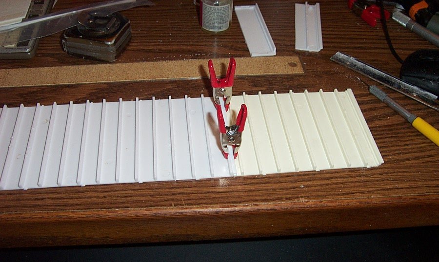
Well the last time I was dealing with the sides of the trailer I was lengthening them to a scale 48 feet.....
Top, Bottom & Sides at correct scale length.... Unfortunately we also need to increase their height. By 1977 most semi trailers in the country had evolved into a taller profile going from 12'6" in the mid '60's to 13'6" standard height in the '70's to early '80's. (todays trailers can be as much as 14'6" in height) This means I have to add a half an inch to the side panels 23 & 1/16th inch length....
Another issue that has to be dealt with also, the molded in, operable door hinges. Adding a half inch to the height throws off the hinge pattern. Three hinges, equidistant apart, centered on the door jamb.
The hinges are molded into the end of the side panel and measure .080 wide and .120 deep with brackets and pins that act as the hinge pin when the door panel is trapped around them. Cutting them off results in shortening the side by .080 so after I've raised the height I will have to glue a piece of stock to the tail end of each side to replace the door jamb. This also means that I will have to scratch build new doors for the rear of the trailer as that is much much easier than trying to adjust the existing doors. Hence, the doors will no longer open. (given the amounts of reinforcement being used to support the long glue joints inside the trailer this in not a loss, in fact it is a good thing) I will wind up using resin aftermarket details to recreate the door hinges and jamb locks.
Now on to cutting my extensions...... (or, giving the micro saw a workout)
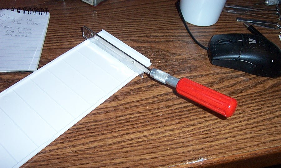
The remaining sides wound up being 13 9/16ths inch long after the lengthening section was removed. The sections removed to increase the height have to come off the top as it is the only way to add it without destroying the details. (the bottom edge of the sides carried the flat channel details that show the attachment to the floor beams so I cannot add anything there. The pic above shows the razor saw being used to first score along one of the bead channels, and once a groove is started for the saw to track in, using the saw to cut almost through the side panel.
Once your about 3/4ths of the way through the panel, you snap it along the cut groove. you then take the edge of a #11 blade and scrape the tiny residual edge off being careful not to gouge the cut in any small location...
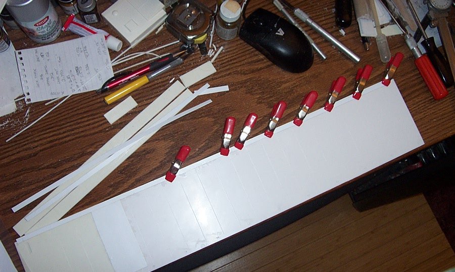
With a little luck, it leave you with a nice straight edge to join to the top edge of the side panel. in the pic above you can see I've cut the second strip off the old side panel. Two strips are required to span the longer length of the rescaled longer side. Making a total of four long tedious cuts by hand.....
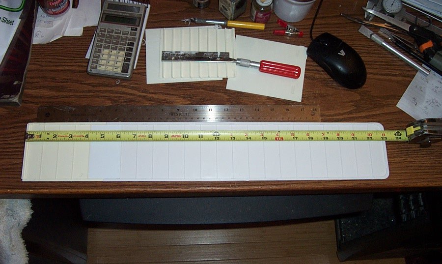
Once those four strips are cut and cleaned, they need to be indexed to each other to preserve the spacing of the vertical rivet details.
This is done by matching the rivet pattern to the side panels rivet pattern, marking an index mark on the strips, and then cutting them off making sure the resultant full length strip is still longer than the side panel....
Once the strips are marked they are cut at the same time so the saw cut has the identical angle of cut on both pieces.....
And the end result is a nice clean joint..... (I put the joint in the middle of the side panels to avoid the issue of multiple joints forming a weak spot in one spot)
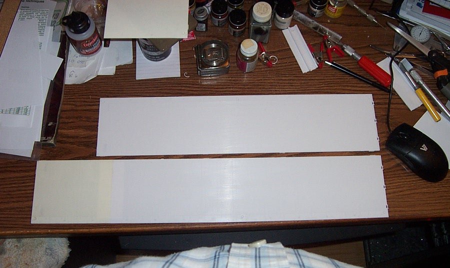
Glueing the strips onto the top of the side panels took the same form as the length extensions, a .020 reinforcing strip is glued the length of the side just short of each end on the inside. Then the strips are glued to the the reinforcing strip from the back side to prevent any liquid glue splurge into the bead detail on the front side. The following sequence of shots shows the process.....
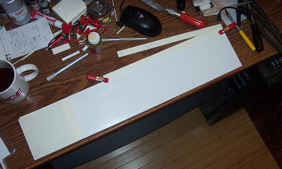
once done, a small tab of .020 is glued over the center joint on the strips. it is then allowed to cure overnight....
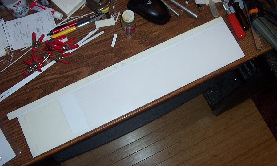
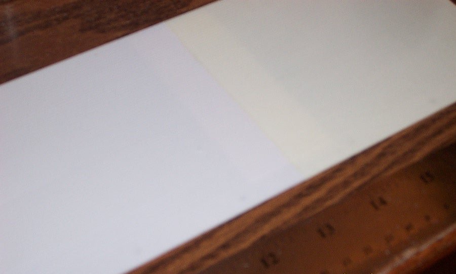
The final results all glued and solid.... So how did the Bead/Rivet detail on the outside finally wind up?
Looks good from here..... I will know better once there is some primer throw on it... but I've always had pretty good results when the photo doesn't show the joint.... (there will probably be some residuals to this procedure but for now, I just want to set the sides to one side and look at something else for a while, like the freezer unit I've got to scratch build, the doors will have to wait until the van body is assembled)
Anyway, that should conclude our expedition into re-scaling well at least most of it....
Thank you for coming along for the trip, and I hope you enjoyed it....
EG
-
6 hours ago, Old Collingwood said:
Nice thorough work EG, reminds me of a job I used to do over here, we used to get Artics 40ft units (the type with a side curtain as well as two rear doors I use to handball unload them single handed.
OC.
Thank you, I like researching the details.... (at least try and get it right)
Single handed unloading... Wow, now that is what I call work.....
- lmagna, popeye the sailor, mtaylor and 2 others
-
5
-
Next Step, The Trailer Bullnose....
The kit part......
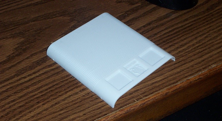
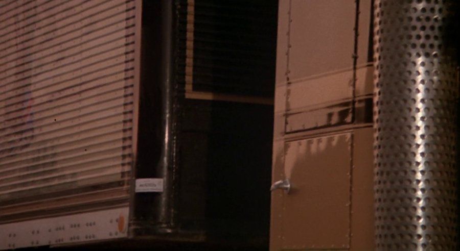
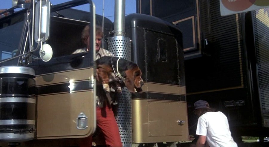
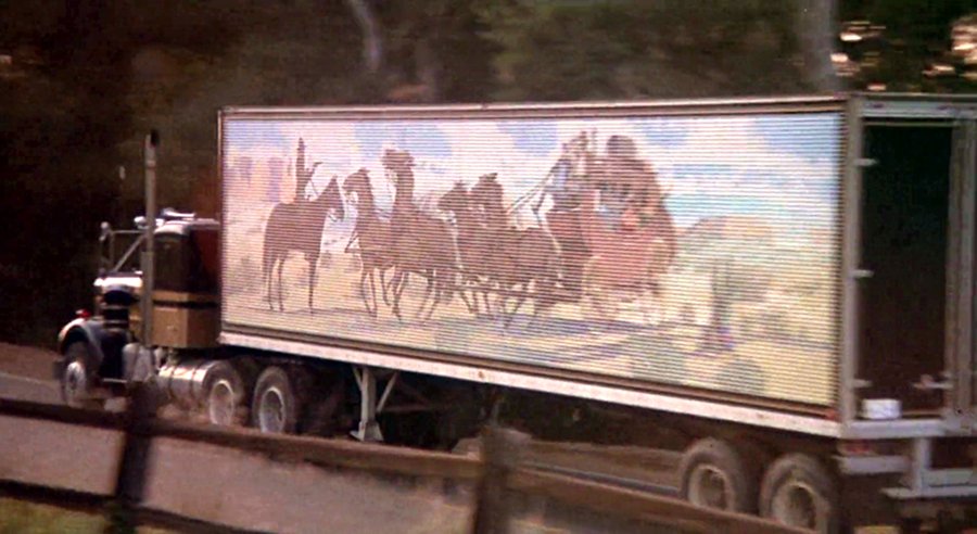
Pretty standard for a '60's period Van trailer, The corners are radiused 12" and the structural beading wraps around and crosses the width of it. So what did the Trailer in the movie have?
Smooth corners, so the beading detail has to come off....
Both sides... now the question all the way to the top?
Yes all the way to the top.... But, notice another thing, the beading does not go all the way to the top on the face of the bullnose either... so we count the beads up the front. 46 corrugated beads up the face of the trailer. This is assuming that they are the correct size. So we need to count the beads on the kit part...
50 beads lines, so we eliminate the detail around the corners and four lines from the top......
But wait a sec, the area at the top of the bullnose is flat, for at least a foot and a half above the last bead line..... what's going on here... Obviously the Trailer Height is too short.
So I take a shot from the movie showing the height and width of the trailer and calculate the aspect ratio. Guess what? the Trailer is a foot too short. Doing my research, I discover that most trailers from the early '50's to mid '60's were 12'6" tall and measuring the bullnose added to the trailer deck height of four feet comes out to a perfect scale 12'6" where the aspect ratio of the trailer in the movie shows the trailer needs to be 13'6" in height.
I need to add a half an inch to the height of the bullnose..... (which means I need to add a half an inch to the height of the sides also)
Razor saw to the rescue.....
I cut a half inch off the other kits bullnose and mate it to the standard bullnose after sanding off the bead detail.....
Now it looks the proper aspect ratio......
So now I have to raise the trailer panel sides this extra height...... I have enough detailed plastic from the remaining kit sides to do this, but have to figure out how to make that long long straight cut and still be able to match the beading detail. It would look awful funny with the beading only going up the sides part way.....
So, the prior step was scaling in the horizontal, the next step, scaling in the vertical.....
Beginning to think I would have been better off scratchbuilding the thing.....
Onwards, and thank you for reading.......
I hope you enjoy...
EG
- GrandpaPhil, hexnut, Edwardkenway and 4 others
-
7
-
-
5 hours ago, Old Collingwood said:
Bit of a set back - tried to tidy up the canopy by using the plastic putty, but no good so I decided to pull the canopy off, I looked over the canopy tried cleaning it up but it cracked, so its now even more no good.
Need to check on ebay - what canopies are around.
OC.
OuCH!!!!
- popeye the sailor and Canute
-
2
-
13 minutes ago, popeye the sailor said:
my question was not for me.........if it can be ordered separate, and it looks doable, then get it for yourself
I thought of that, but unfortunately, this is what I need to build.....
Minus the collector and grille of course, unfortunately there is no aftermarket for such.... Even if there was, it is a simple box, much cheaper to scratch it....
- Old Collingwood, mtaylor, Canute and 4 others
-
7
-
I've always found that it takes longer for a manufacturer to send replacement parts than it does to ship out a full kit, usually a month or two.......
But you guys are beginning to give me the itch for WWII US Navy birds again..... (the budget boss, and chief accountant, is not going to be happy)
- Canute, Edwardkenway, Jack12477 and 4 others
-
7
-
I can look around in the aftermarket world and see what there is, I know that Moebius puts out a Great Dane Trailer with a more current Thermo King unit as a 2-n-1 kit....
Just checked....
Yes they do Moebius #1303 which is the 53' Great Dane smooth side with optional reefer...... also current production. (still has the rear roll up door also)
-
Yeah I have the artwork.... A composite from several screenshots of trailer #2. I had to recreate the upper right corner myself.......
Still need to scale it a bit and a tad more cleaning up but I'm good here. Not sure if I'm going to print it myself or have a custom printer do it on an Alps printer....
Oh and those two Moebius Kits? they are current production, you can get them from amazon..... or your local Hobby Shop if they stock them.... The AMT Coca-cola kits are also current production if you want to duplicate what I'm attempting to do. The Reefer unit is incorrect for this build so I'm probably going to have to scratch build it anyway, so much for needing the old classic Watkins kit.
EG
- hexnut, Canute, Edwardkenway and 5 others
-
8
-
I will enjoy watching this come together....
-
2 hours ago, popeye the sailor said:
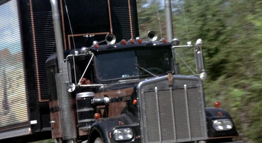
our Freightliners differ from year to year....every year we get new tractors. we have Cascadias , but I believe Freightliner also makes a Pro Star model as well......they are newer models 2010 and up. we used to run Internationals, but did away with them for a few years. I hated them, because they had aluminum clutch pedals.....when we did truck washes they were very slippery. we used to line them up outside, and a company would come in to wash them. one time, I was parking one........just got her in the slot and my foot slipped off the pedal! scared the S____ right out of me! last year, we started to bring them back into the fleet...think we have around twenty now {our DC has over 200 tractors}. other DC's run Peterbuilts and Kenworths.......one Dc ran Volvos. nice model Craig, but not the tractor we run
 I'm in no hurry.....with all the projects I have going, the admiral would have a full bird Kernel, if I brought anything else into the nest.
both of those trailers are Fruehaufs.......Watkins is just the carrier's name. insignificant, but I though to mention it. elongating a trailer like that is going to change the locator tabs for the tandem rails. did they make the model so that the tandem slides front and back? that's a neat feature, although useless if the model is to be static. I saw the Coke trailer and wanted to get it {there is a coke collector series...AMT makes a bunch of models in it}....but the admiral shot me down. as I said......I have too many projects. there aren't too many trailers with textured roofs........most are smooth. some even have the clamp style molding around the edges. back in the day, Wally's logo was very different than what we see today. the sides were ribbed.......they were dubbed with the name 'circus trailer'........48' in length and that is how they looked. I knew little about air brakes....just the few questions asked on the ASE tests. I must have gotten them right, because I got my brake certification. the older trailer.....Fruehauf, trailermobile, Wabash,..........they were mongrels......you never knew what suspension they had. some were Dana, some were Eaton........we were forever mixing and matching parts kits to make 'em work. the drums were the worst.......whether they were inboard or outboard.
Popeye, or if I may call you Denis?
First, Moebius #1301 is the 2010 International Prostar Tractor, and Moebius #1302 is the 53' Great Dane smoothside trailer to match. It even has the roll-up door on the back..... They go together I suspect. There was an aftermarket resin supplier from Europe that used to do a Cascadia conversion kit, but it is no longer among his website offerings and besides, he is on temporary hiatus due to the CV-19 virus. Hopefully he comes back.
You would be in the $130.00 range for both.
I understand SWMBO's and marching orders The last kit combo I bought and she was suggesting that I might take a trip to the moon if I bought another . (1/72 scale Dragon Saturn V and the Apollo 10 setup)
I checked the transfer yard they built at the rear of our Wally World yesterday, all Cascadia's except for one Prostar & two Lonestar's, the Cascadia is the better looking truck in my opinion.
Yeah they are both Fruehauf FB's AMT has released this kit in many different livery's over the years with and without the reefer unit. It represents the cutting edge of trailer construction long about 1963-66 or so...... but it still sells although it pretty much represents nothing currently on the road. And I'm building a '77 Hobbs dry goods van, which were built by Fruehauf anyways so the details are right on the money. Of course in the train of kitbashing this, most of the locator pins have to come off, they don't line up anymore. So I'm still kind figuring a way to line them up correctly.... (probably install my own locators and reinforcements but haven't yet figured out exactly how yet)
Anyway, just having fun here while in self imposed viral lockdown.
EG
-
4 hours ago, yvesvidal said:
This is the only type of surgery I enjoy watching.
Yves
I'm very happy you are enjoying it, I keep practicing my plastic hacking and someday, hopefully, I'll get good at it....
EG
-
Tractor build is unfortunately on hiatus waiting for parts......
So we continue by starting the second half of this build, the trailer.......

First off the kits.....
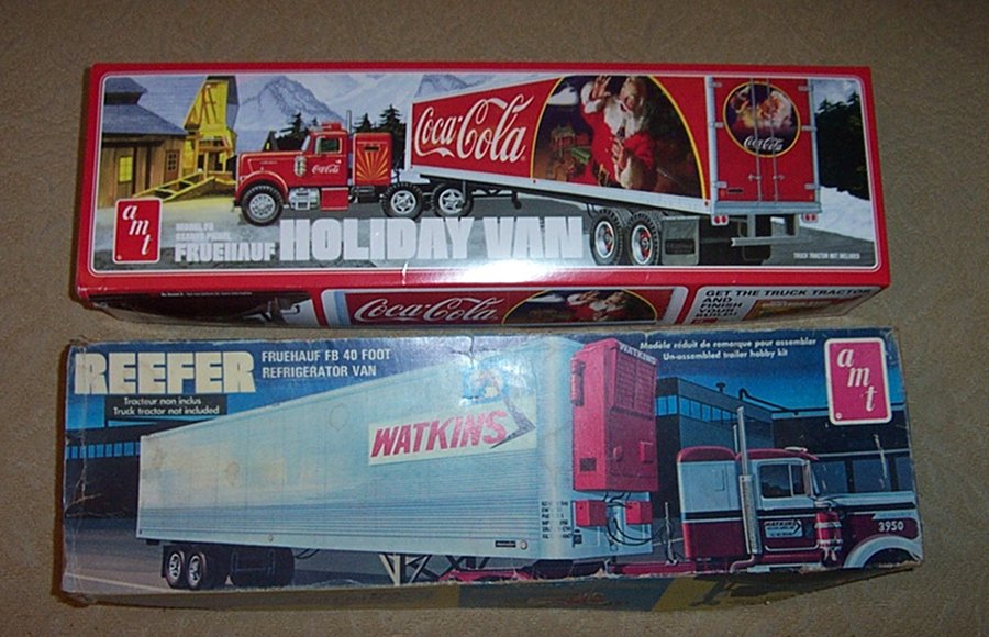
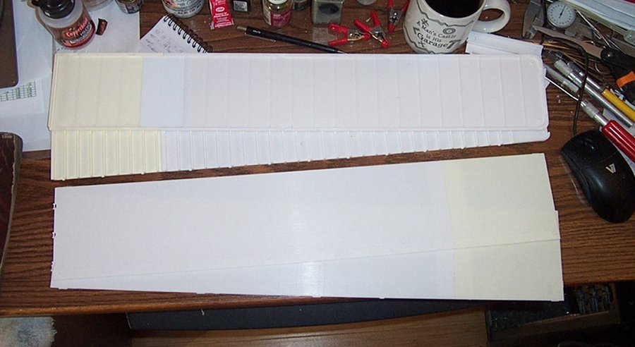
The kit at the top is a 2019 AMT holiday Coca-Cola van, a 40' Fruehauf model FB. The kit at the bottom is a 1970 AMT Watkins reefer trailer model FB. believe it or not, except for the reefer unit in the '70 kit, they are identical.
The instructions....
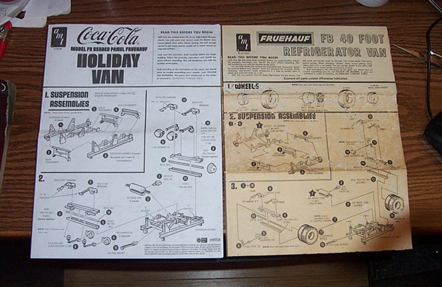
As the base model I'm using the newer kit and the older kit for the parts to enlarge the trailer to the proper scale size. (the older kit is a builder and not a collector grade kit)
The parts.....
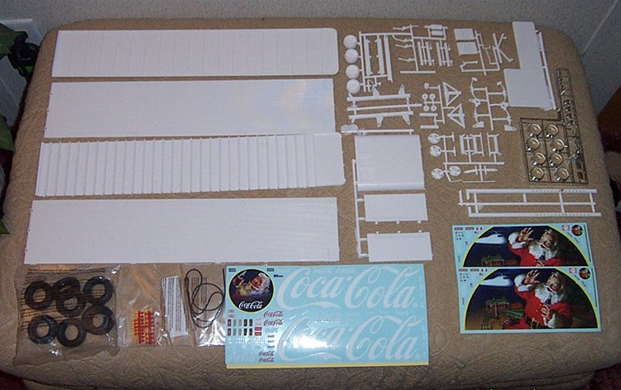
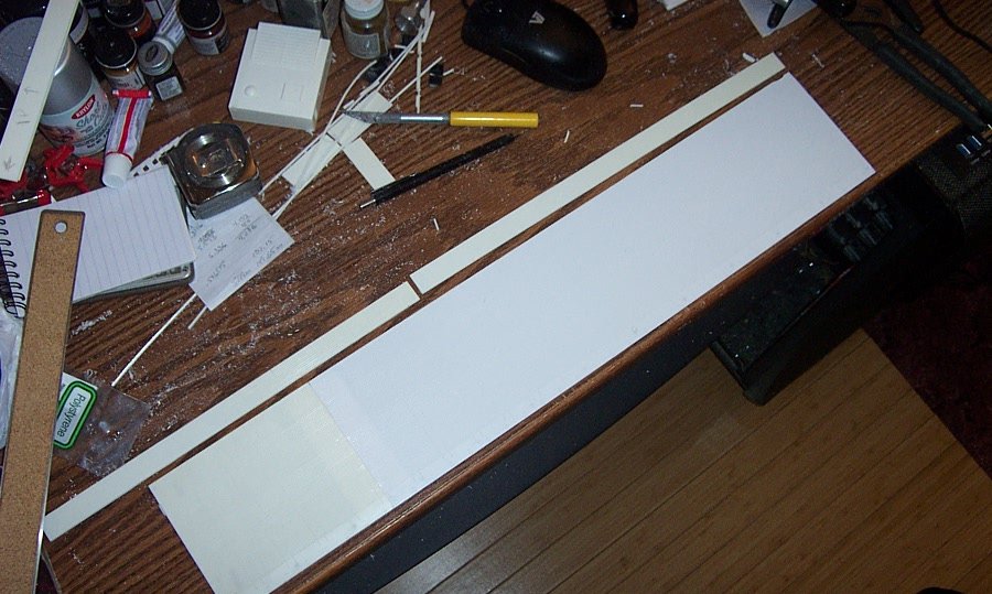
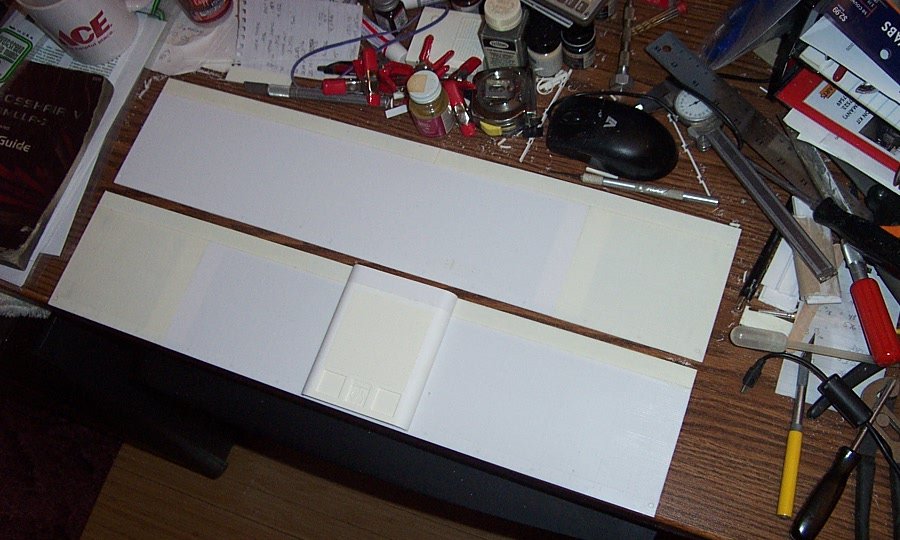
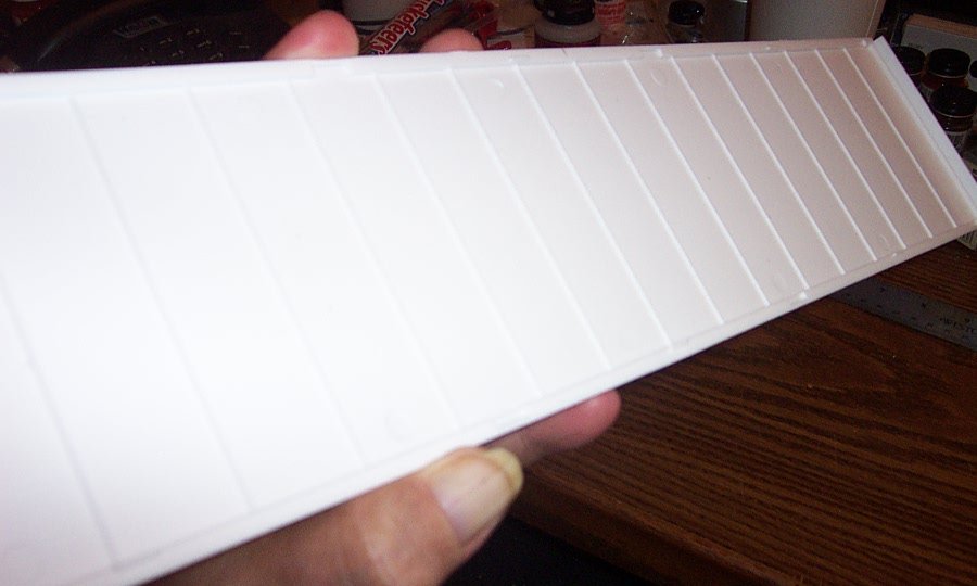
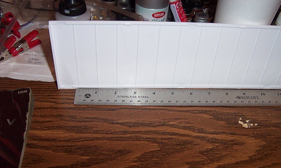
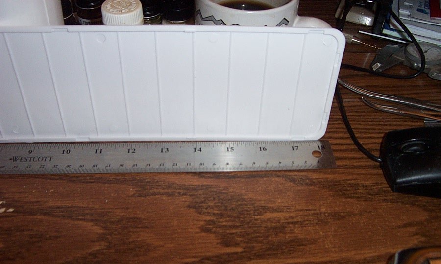
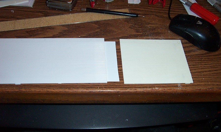
The trailer measures 19 1/16th inches long not counting the reefer unit, this is a hair short for a 40' trailer in 1/25th scale.
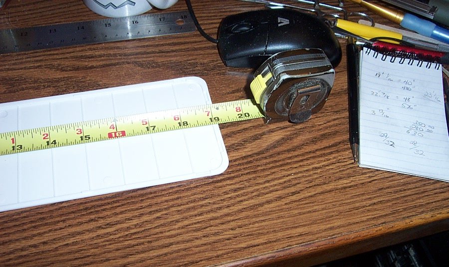
And I need to lengthen it to a scale 48' which should be 23 1/16th inches long so it's four inches I need to add to get to the correct scale length. Well let's examine the parts....
The parts are highly detailed, actually amazingly detailed....
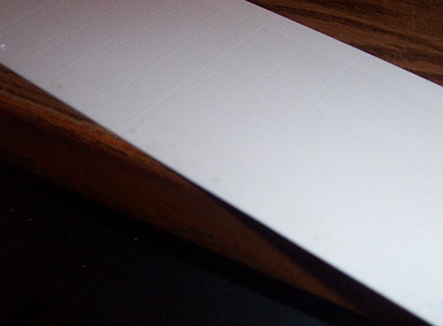
Side beading and rivet details......

Looks just like the beading details on the side of the movie trailers.....
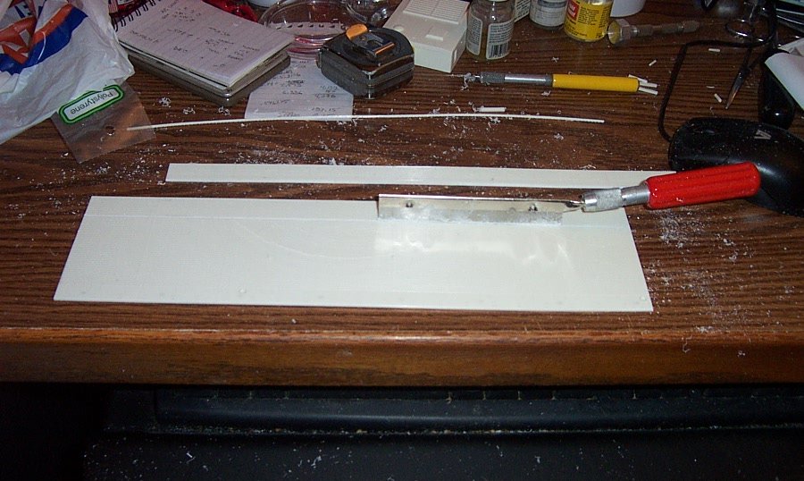
The inner roof panel....
Shows the cross ribbing to support the roof.... (very glad this detail is there makes the decision on where and how to cut easy)
Why does this aid the rescaling of the trailer length? Well, on the real world trailer those ribs are on 2' centers so if I need to add 8 scale feet, and the rib distances are in scale, all I have to do is cut and insert 4 sections from one roof into the other.... so are the ribs to scale?
Laying the rule down next to the roof, we see that the ribs start out pretty much on 1" centers, at 1/24th scale, 1" centers are perfect, but we are working in 1/25th scale.... the centers should be gradually falling behind the inch marks on the ruler...
Checking the other end, and yes they do fall a little behind the ruler graduations as they reach the length of the trailer, the ribs are in scale... I need to cut out four bays.....
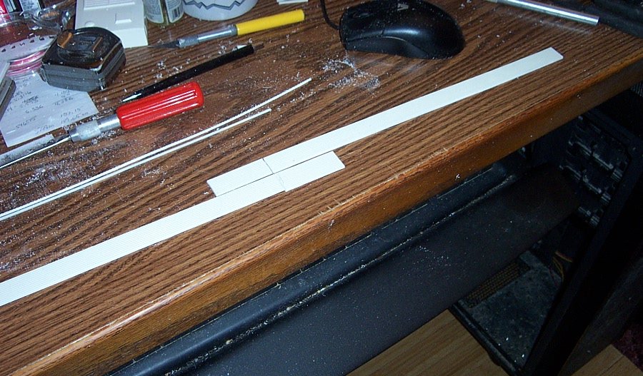
I don't count the first bay because it carries the door jamb for the rear doors so I take the next four bays off the old trailer roof. Next is taking the first bay off the new trailer roof..... (trusty razor saw works great here)
Then cleaning the edges, mating them, and checking the length......
Ahhh!, 23 1/16th inch long and perfectly straight. but while they were seperated I used both pieces as templates to cut the sides and floor of the trailer.... (you can see the parts under the razor saw in the above picture)
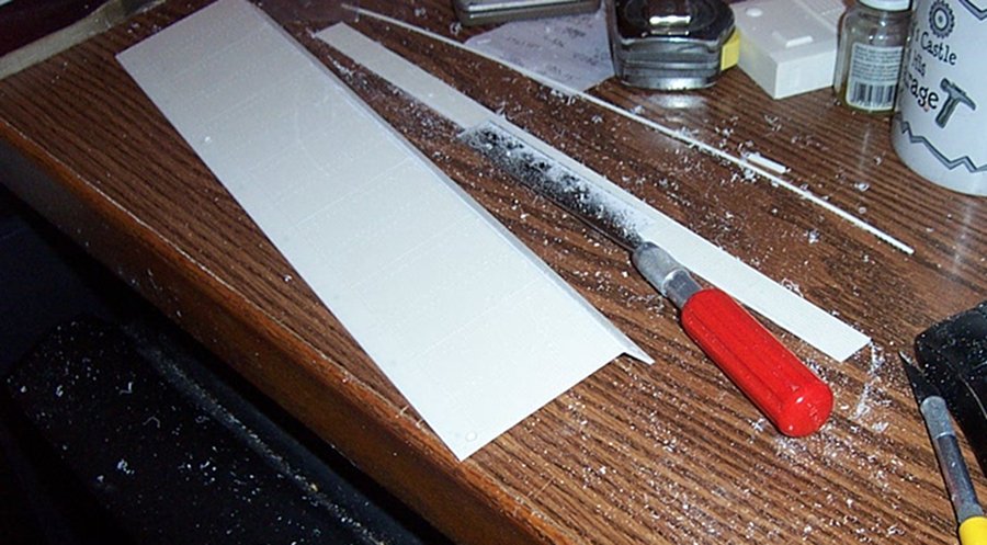
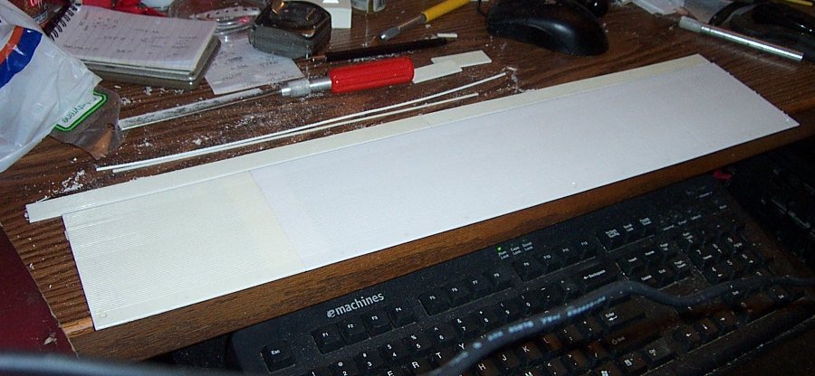
So, how did we do with the bead details on the sides of the trailer following this procedure?
The joint line won't photograph, the older kits plastic is seriously yellowed over time compared to the newers pristine white and that is the only way to tell where the join is....
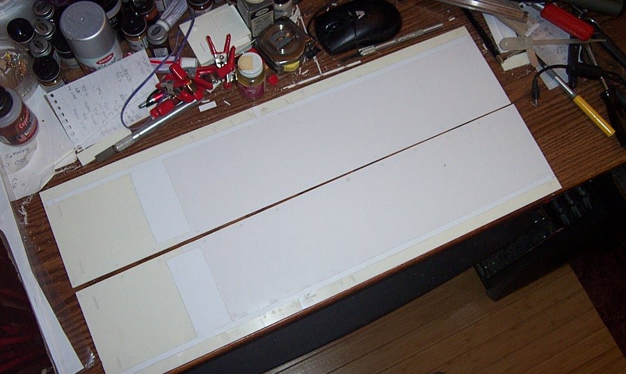
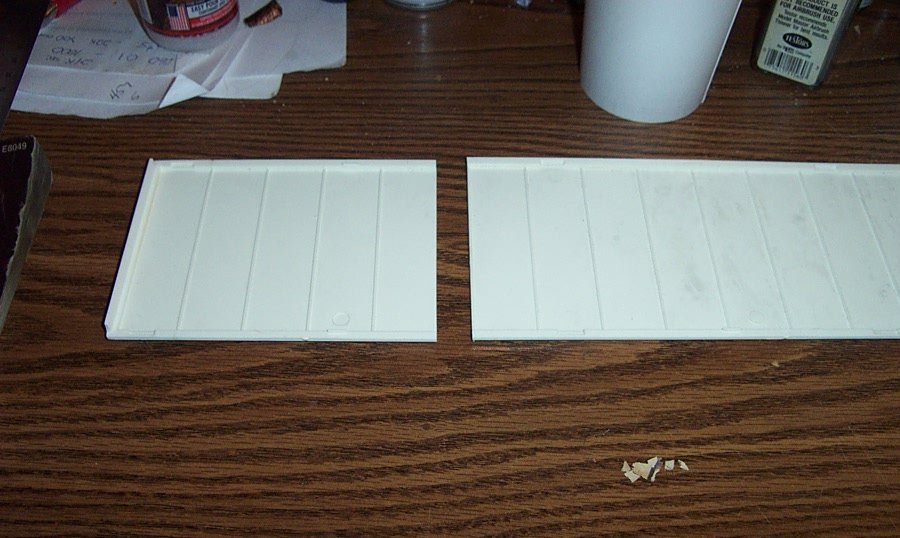
So what does a 48' trailer side look like compared to a 40' trailer side?
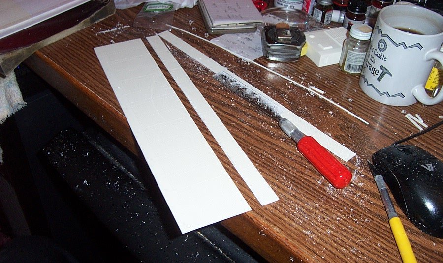
Extending the floor panel.....
And the other side.....
Now, I have a trailer that is the correct length.... Next step, accurizing the trailers bullnose..... and checking for scale height......
- GrandpaPhil, Canute, mtaylor and 9 others
-
12
-
Prayin for your speedy recovery....... We are pretty much on lockdown already we are both well over 60 and the SO is recovering from pneumonia already.... not fun and it takes a while they tell us....
Please stay in touch if possible......
- Javlin, mtaylor, popeye the sailor and 3 others
-
6
-
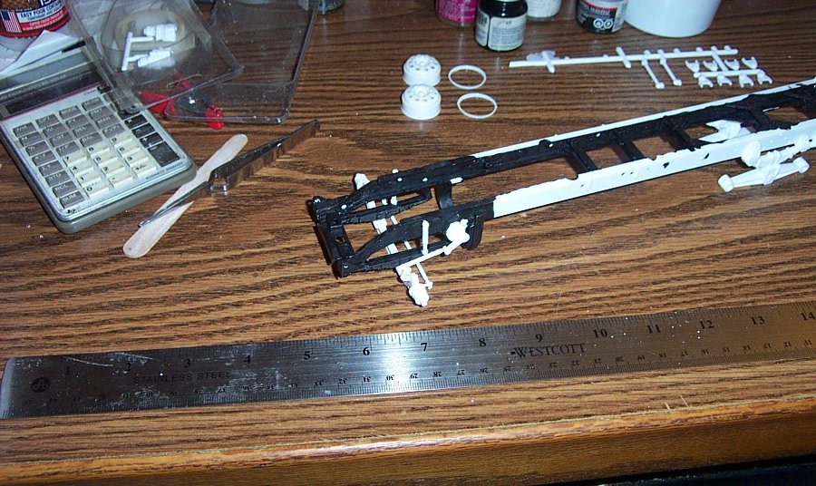
Next up, Wheels and Tires.....
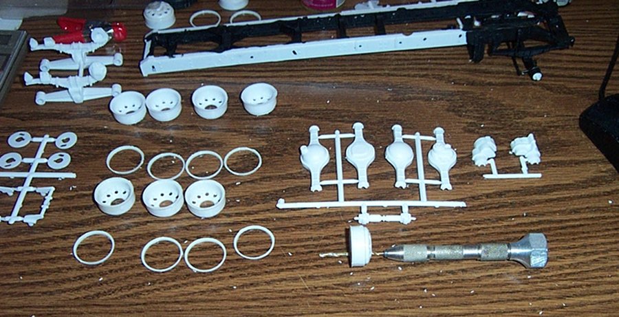
The Truck had ten hole Alcoa aluminum wheels..... In the kit they are chromed which had to be stripped off before assembly. Chrome is applied to plastic parts the same way it is applied to car parts, Electroplating. What they do is spray the rack of parts with a conductive lacquer which allows the electrolysis process to take place. So when stripping you need to remove both the plating and the lacquer. This is not an easy proposition. back in the day the usual product used for stripping chrome was concentrated Chlorine Bleach. Good old Clorox. Pour some into an open container and allow the parts to soak til the chrome was gone, a process that usually took a couple of hours. Except this is 40 years later and the concentrated bleach isn't as concentrated as it once was. After three days, there were still large patches of chrome remaining and it wasn't touching the lacquer. Time to find a new stripping medium. I knew of all the other suggested mediums which work to some extent, (oven cleaner, brake fluid, windex and a brush, etc. etc.) I discovered a relatively new product for completely stripping chrome off plastic parts. It is called "Super Clean" I use it in a closeable jar, (1pt mason jar) and just drop the parts in. Within three hours soak, the chrome is gone, overnight the lacquer is gone. No scrubbing, no unpleasant smells, simple and easy, a clear water rinse afterwards and your good to go. And the mason jar of super clean is good for several kits before it needs changing and another plus it is biodegradable and non toxic, I mean, I wouldn't drink it after all it is a powerful oxidant chemical but it will not hurt the septic system or anything in nature... Modern chemical technology.....
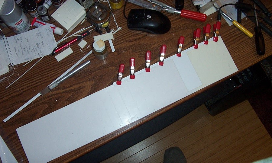
The stock AMT wheels consist of 20 parts. A rim and a seperate front bead. Ten vinyl soft tires mount to the rims much like the real thing. The first step is to clean the flash from all the parts. that is what I'm doing with the pin vise, drilling out all the holes.....
Then we glue the individual front beads to the rims.....
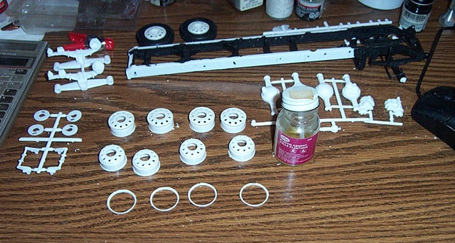
In the back of the pic above the frame you can see the two front wheels already done with their tires mounted. (test fit)...
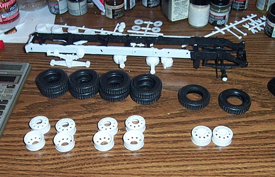
Wheels all glued up and cured overnight, one of the problems with AMT split rims is they do not stand up to mounting and remounting the tires, the separate front rim will split off, so this is a tricky part. and they are ready for initial painting....
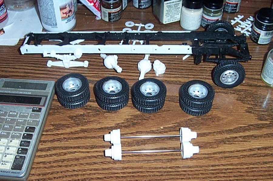
Painted and Tires mounted, actually beginning to look like something here. The fronts are slipped onto the front axle temporarily and I'm getting ready to assemble the duals. and, I run into another major problem.... (two problems in fact) First, the drums mounting flat does not match the flats inside the rims they are a full eighth of an inch too large! The rims do not fit the drums out of the BOX!!! Looking inside the drums, there isn't enough material to simply turn the mating surface down to fit the rims. Major surgery here to fix this...... The second problem is with the vinyl tires, they stretch, particularly around the bead area when mounting and unmounting them which means they do not stay where they belong on the rims.... Very poor situation for such an expensive otherwise well made kit. Also no way to correct this easily with the kit parts. Now I'm sure that Round 2 will replace the bad parts, but they will be sending the same parts that do not work now. So that is kinda defeating the purpose.... So I'm stuck now I cannot continue until I resolve the Wheel/Tire issue. Probably go aftermarket and replace the entire set of rubber.... Besides the vinyl tires in these kits have a habit of not ageing well. remember the old vinyl car seats and what happened to them after a few years? all cracked and split? well the same thing happens to these vinyl tires over time, they dry out, split and fall apart..... Yeah, Aftermarket is the way to go.... Resin wheels and true rubber tires....
So the tractor build is now on hold..... awaiting suspension parts and replacement wheels and tires...... Don't know what else to do at this point......
But then again, I have an entire 48' trailer to kitbash......
Next up, kitbashing a 48' Hobbs reefer van trailer......
-
-
Paint and decals look pretty good to me also..... I built this kit a couple of decades ago....
I painted it up in it's USAAC version......
Unfortunately it met it's fate many years ago when grandson was doing touch and goes with it.... (he couldn't quite get the correct rate of descent when trying to land, he always picked short runways also)
Good looking bird, the night penetrators were especially disliked by the Luftwaffe....
-
1 hour ago, Jack12477 said:
Thanks! Could not find that in the manual
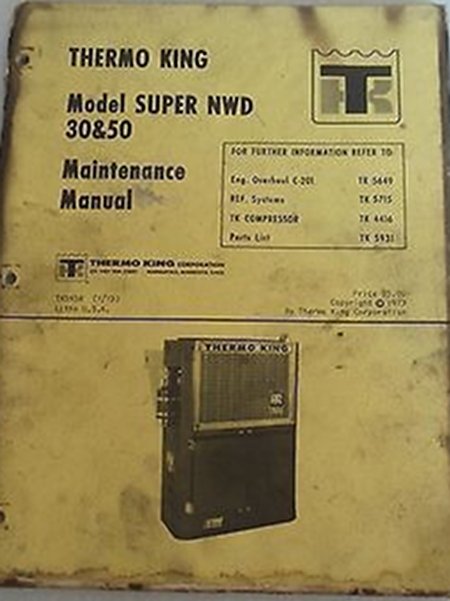
You wouldn't find it in the operations manual, you will find it in the maintenance manual for the IHC M-3 Halftrack
Look up these tech manuals.....
TM-9-707 1943 IHC Halftracks
TM-9-710 1944 Basic Half-Track Vehicles -White, Autocar and Diamond T
TM-9-1710 1942 Powertrain (Axles, Transmission and Propeller Shaft) for Half-Track Vehicles
TM-9-1710C 1942 Chassis and Body for Half-Track Vehicles
They are all available for download online in PDF format everything you could ever want to know about WWII half tracks and they specifically cover the M-14 multiple gun motor carriage. the only difference between it and the M-16 was the M-14 had two .50 cals and the M-16 had four.
- Canute, popeye the sailor, mtaylor and 3 others
-
6
-
The reason they changed from the Torsion Bar to Walking Beam was the problems people were having assembling it. unlike the resin aftermarket, the kits torsion bars were separated from it anchors. which meant alignment problems and small gluing areas for attachment... It was very fiddly to get correct and then if built correctly very fragile......
In researching the truck, I had an email exchange with one of the property masters that worked the film and he told me what the trucks were model wise and when I asked him if they were true W925's he said yes..... I later confirmed this with a couple of shots from the making of forum... (no longer online unfortunately) Prior to 1970 heavy trucks were designated by their axle weights and suspension types. W925 stoof for "9" series truck, "2" for tandem axel, and "5" for type of suspension... and the "5" was torsion bar...
The breakdown runs like this....
K121/W921 (4x2) Single rear axle. Spring, air, or torsion bar suspension.
K122/W922 (6x2) Tandem rear axles(one is a drive axle, and one is a pusher/tag axle) spring(not sure about air)
K123/W923 (6x4) Tandem drive axles 45,000# GVW spring(Hendrickson Walking Beam or similar) or air
K124/W924 (6x4) Tandem drive axles 55,000# GVW spring or air
K125/W925 (6x4) Tandem drive axles 46,000# with torsion bar suspension
A note on the K & W designations.... "K" stands for Kent, "W" for Worthington. those were the last names of the partners that created Kenworth Trucks a contraction of their two names. in the model designations the Kent Series were the cabovers the Worthington series were the conventionals.... The first number was the model number so the 9 represents the 9th design for a conventional truck the two stands for the number of axles and the last number for the type of suspension....
since the '73 in the movie was registered as a W925, it tells you everything you need to know to put the correct suspension on the truck...
- GrandpaPhil, CDW, CapnMac82 and 6 others
-
9
-
47 minutes ago, Roger Pellett said:
Nice model! Looking it the driver has a conventional steering wheel that I assume is connected to the front wheels. With the weight on the treads it would seem to be also necessary to vary their speed relative to each other to maneuver the vehicle. How does the driver do this?
Roger
He doesn't, the bogies are driven by a rear axle with differential just like any other wheeled vehicle... when you go into the turn, the differential handles the difference in inner to outer speed.... The rear return roller just freewheels....
-
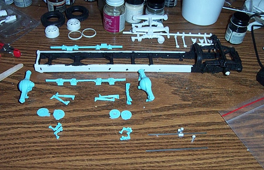
Step 2, The Frame...
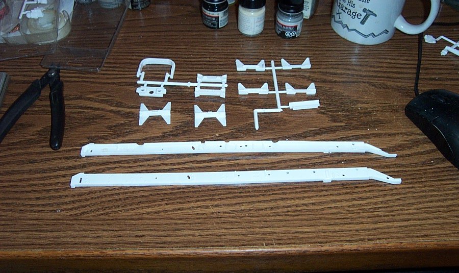
13 parts, fairly well detailed. one of the things I've noticed about these early AMT kits is the level of accurate detail. It is right up there with many of today's models in the accuracy department. There are other issues with this late '60's injection molding tech, but they didn't short the details.
First step checking for rail straightness....
As we can easily see the left hand rail is not straight, (they are upside down in the pic) but I can work with it. (this was after several hours of hot water bath and gentle persuasion to bring it back straighter than it was out of the box)
The cross members are in two halves believe it or not, this makes it easier to assemble. I've painted them black on the interior sides cause you will never get spray into all the nooks once it is assembled.... Note you can still see the curve to the left side rail laying flat on the table....
Now the instructions say to mount all the cross members to the left side frame first and then cap it with the right side, But doing that with a bent frame rail with result in a bent frame. We of course need this frame to be as straight as possible.... So what I'm doing here is taking the strongest cross members and mounting them first..... (you can still see the curve to the frame)
Glued together and left to fully cure. the tail is square and the long sides of the crossmembers give a large contact area to pull the two sides straight.....
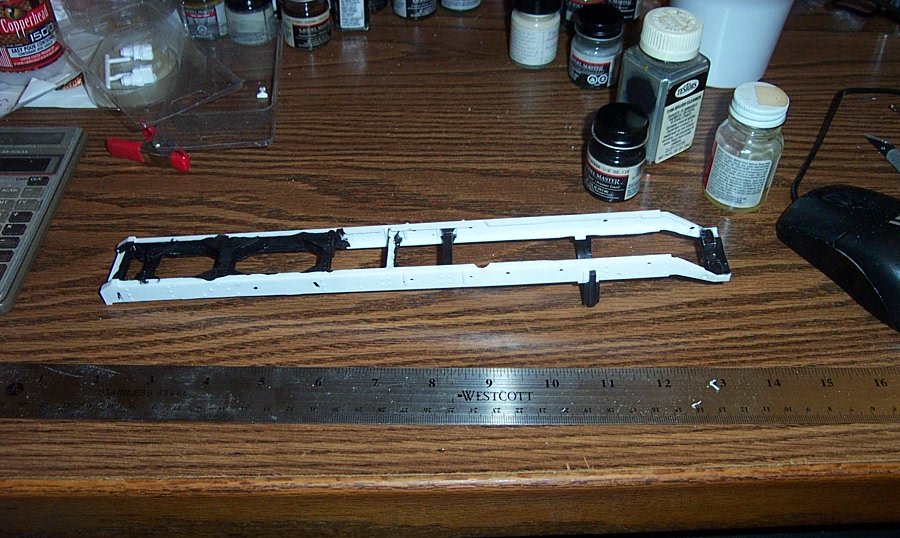
I mounted the four remaining cross members one at a time, using the rule to set a straight edge while the glue set. this allows the curved left rail to be drawn into alignment with the right side and hold there... the end result? straight as an arrow with no warps.....
At this point, I check scale, and it's right on the nose! at 1/25th scale it should be just under 12" long
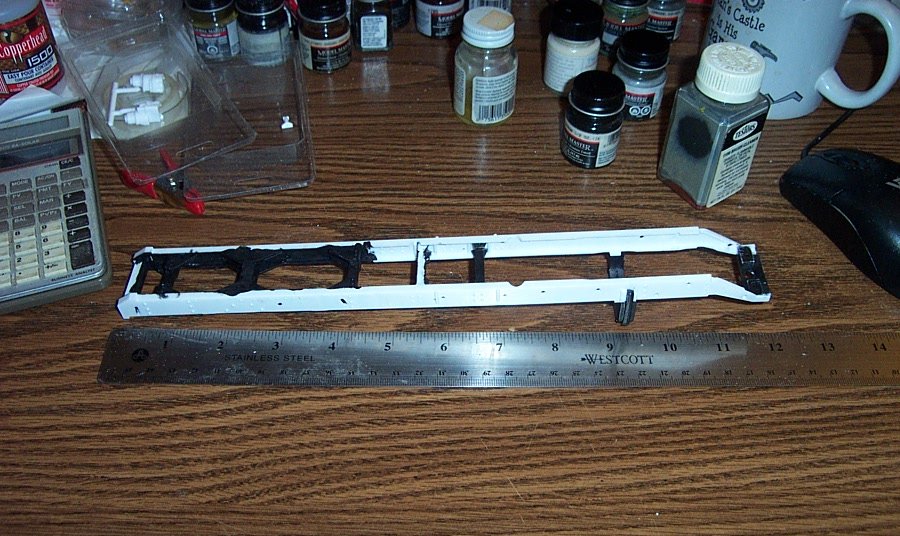
Next step is adding the suspension parts Standard leaf spring straight axle front end and Hendrickson Walking Beam rear end. Now I'm not mounting the rear suspension cause I will be changing it to the required Torsion Bar suspension... I'm using it to support the frame while assembling the front end.....
Front suspension completed except for painting, I took the pic here so you can see the detail. once it is painted black it will disappear....
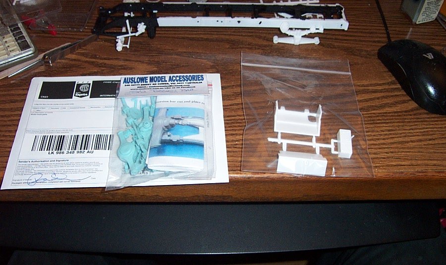
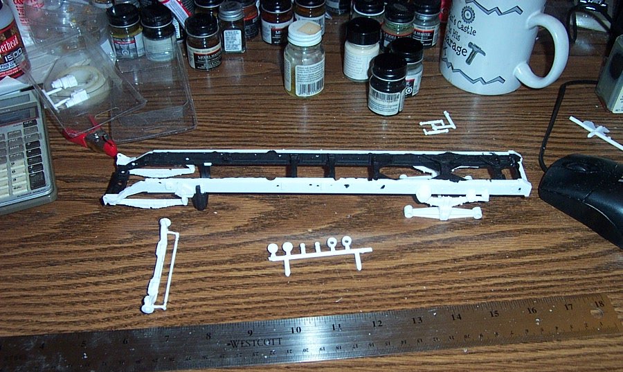
Aftermarket Torsion bar suspension, comes out of Australia.... on the right there is a second Battery box step from Round 2 models for the curbside of the truck.
Laid out you get a general idea of what the torsion bar suspension actually is, they ride outside the frame rails and connect to the axles by way of linkages that twist the bar when one side or other need to travel up or down... a very smooth riding system I'm told but many truckers especially heavy haulers say it doesn't have the load carrying capacity of the walking beams. Hence they don't like it....
But this also reveals my first hitch/hickup on this build, the linkages to attach the axles to the bars are not in the package everything else if there but the four parts needed to make it work. The gentleman from australia tells me that he will make them up and get them out to me. but it may be a while. The guys who do the aftermarket in the truck modeling world manufacture to order. Which means that when you order you go on the production list behind those that ordered before you... The suspension kit took a full month to get to me... and now I have to wait another month for the linkages.... so to save the gent the shipping, I ordered a few more parts I would eventually need. another month later, they arrive in good shape. I'm sure you guessed it, no linkages... Turns out he got his orders mixed up and sent the replacement linkages to another modeler. I'm now waiting on the linkages... but I figured that I would go ahead and assemble the Walking Beam suspension so I can at least continue the build.....
Thank you for looking in and following along....
Next up Wheels and Tires.......

B-25 Mitchell "Meet Miss Runyon" by Javlin-HK-1/32
in Non-ship/categorised builds
Posted
Just plain speechless.....