Rik Thistle
-
Posts
804 -
Joined
-
Last visited
Content Type
Profiles
Forums
Gallery
Events
Everything posted by Rik Thistle
-
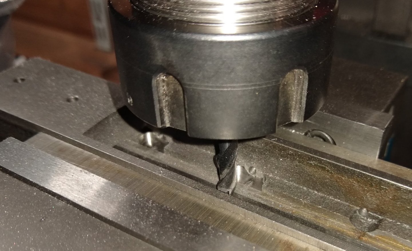
 You didn't have an 1/16" end-mill ? I forgot to mention I did try a 1/16" end mill initially, taking about 0.002" - 0.003" cuts...it lasted one and a half passes before breaking...I was taking it very slowly, high rotational speed, lubricant etc. A 1/16" end mill would have allowed me to used Stuart's 3/16" x 3/8" supplied bar. I had bought two 1/16" mills for this job; they weren't the most expensive but I hoped they would have lasted longer. There may have been something in my set-up that caused the mill to break but I couldn't see what. So I switched to the slitting saw. My gut instinct made me wary that a 1/16" diameter cutter on Stuart's mild steel was pushing it. Richard
 -
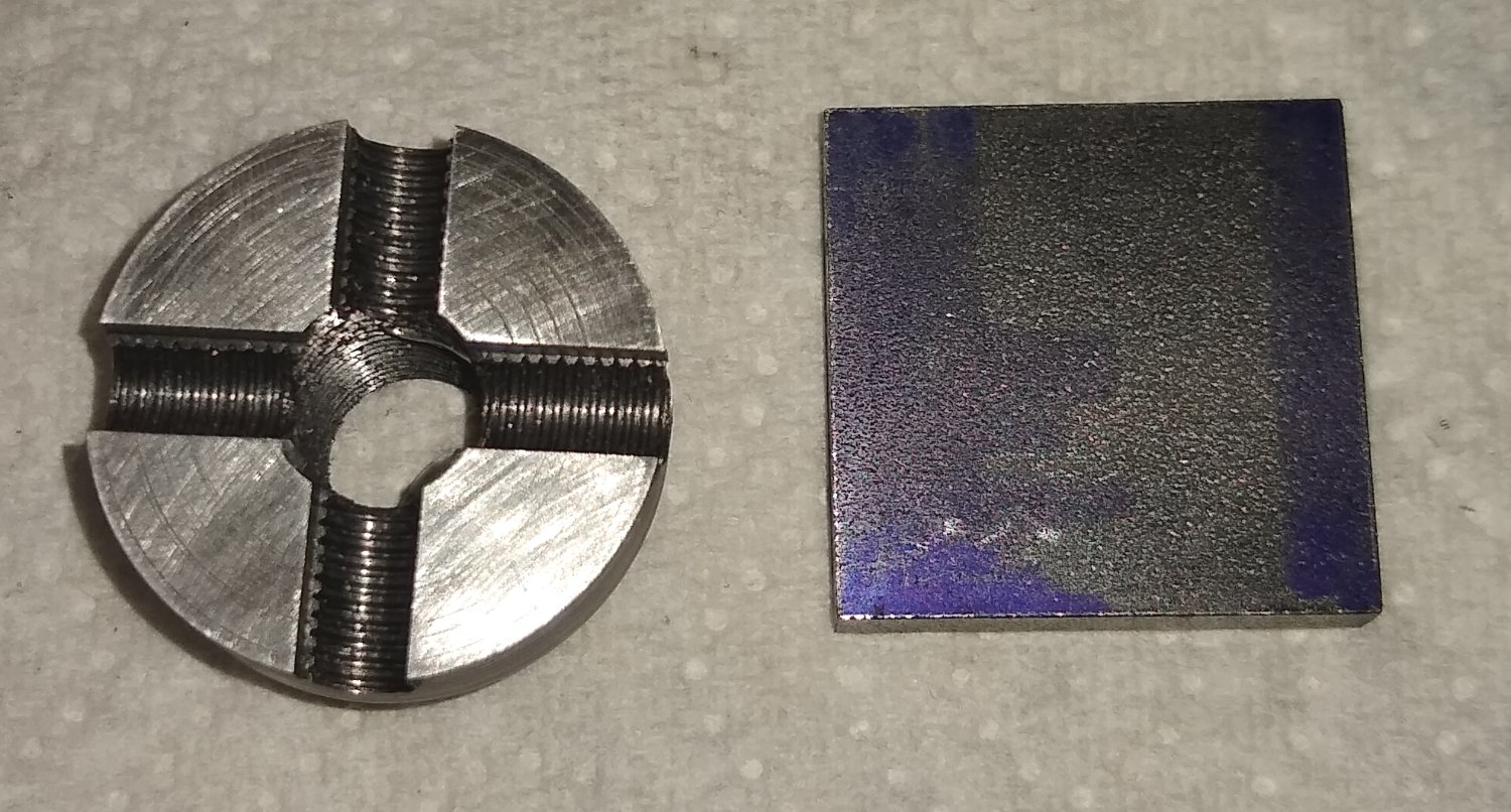
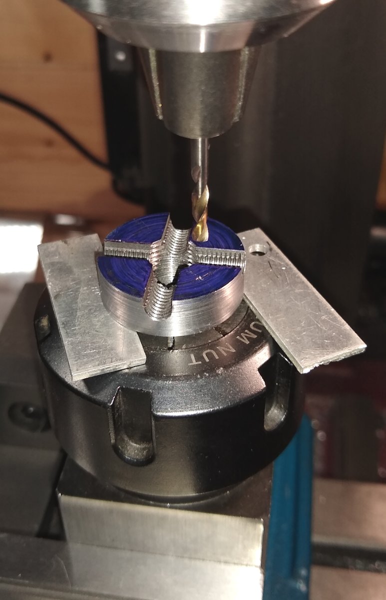
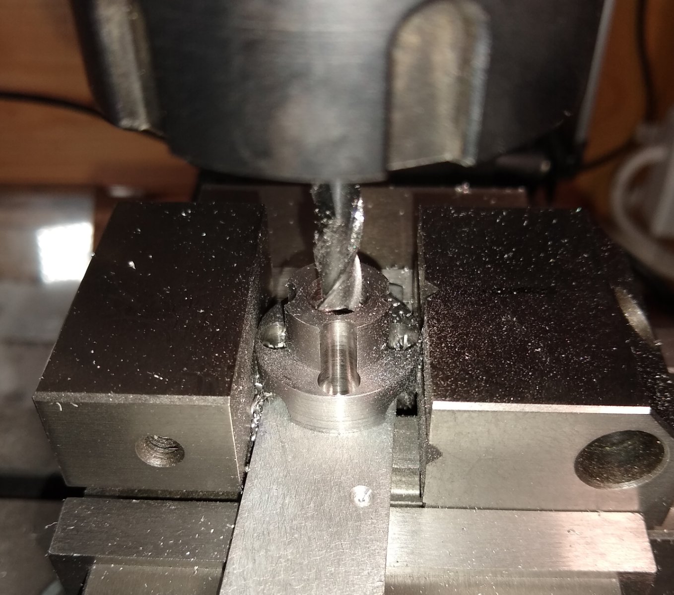
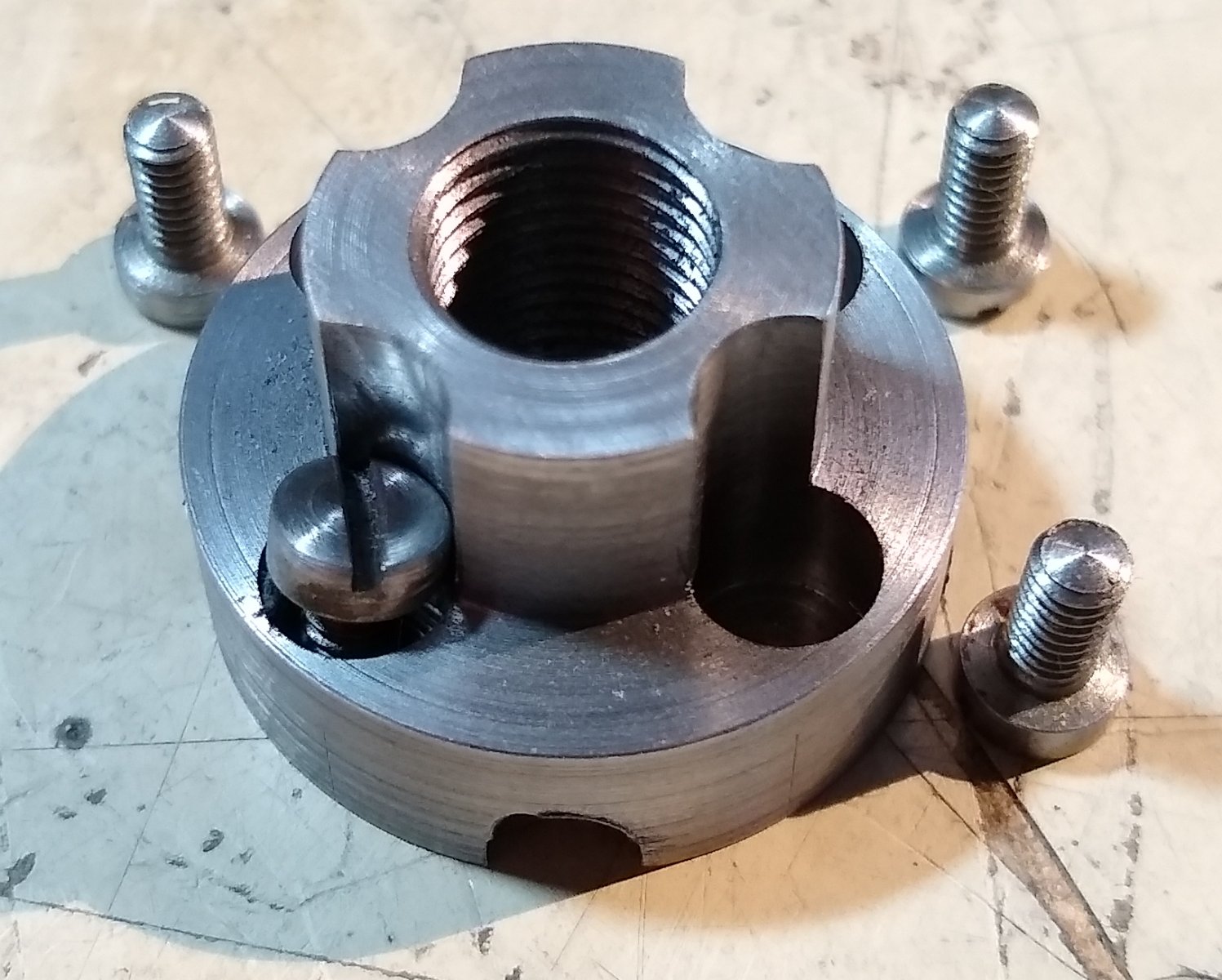
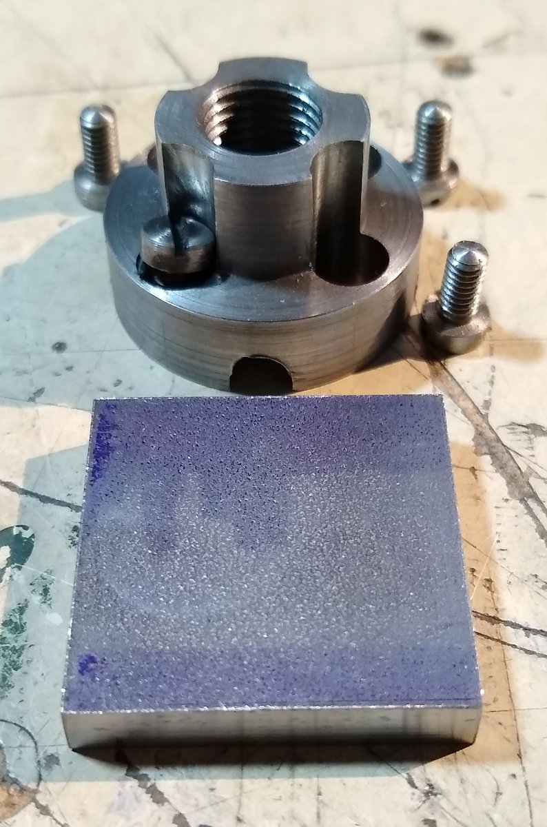
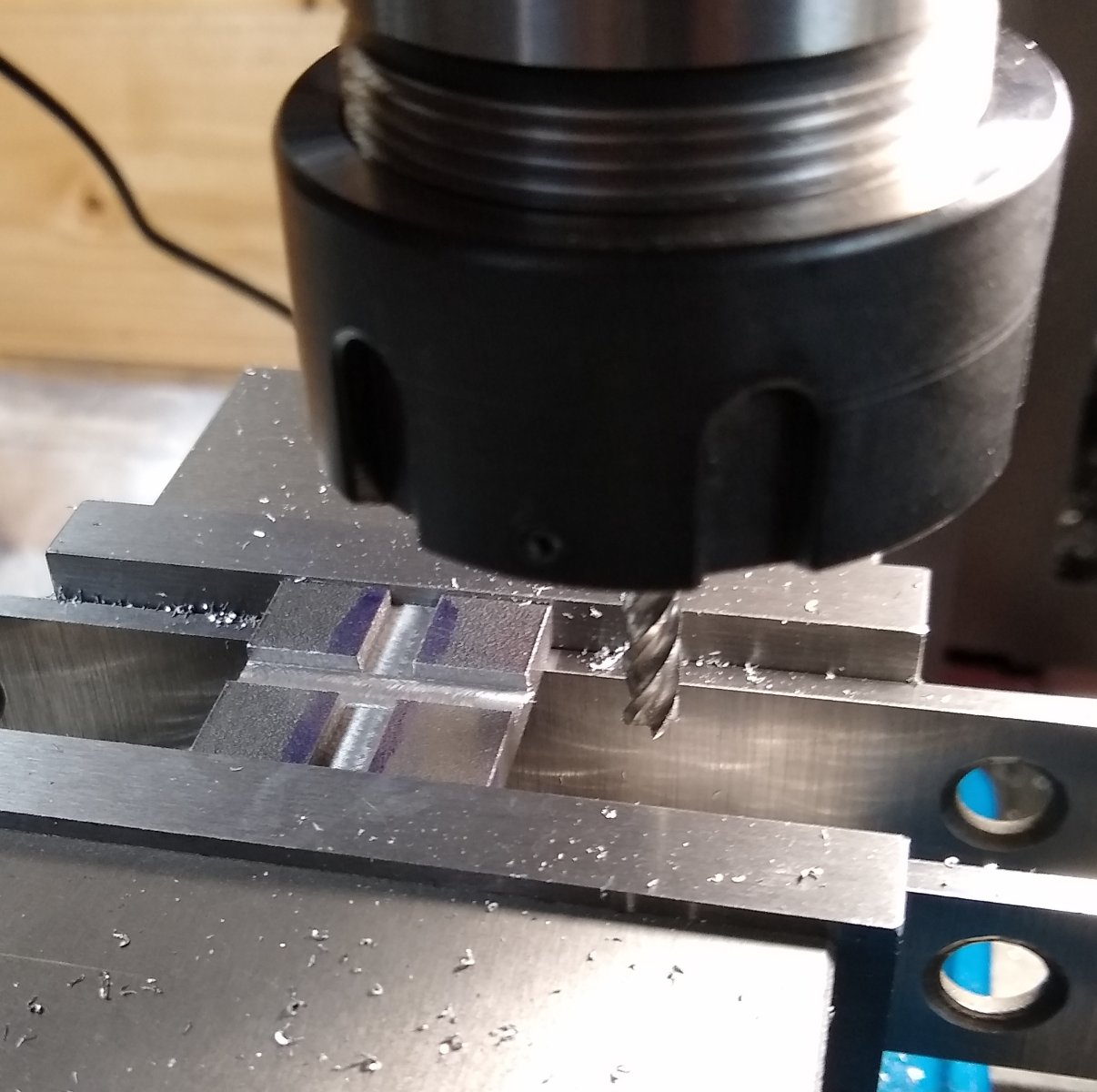
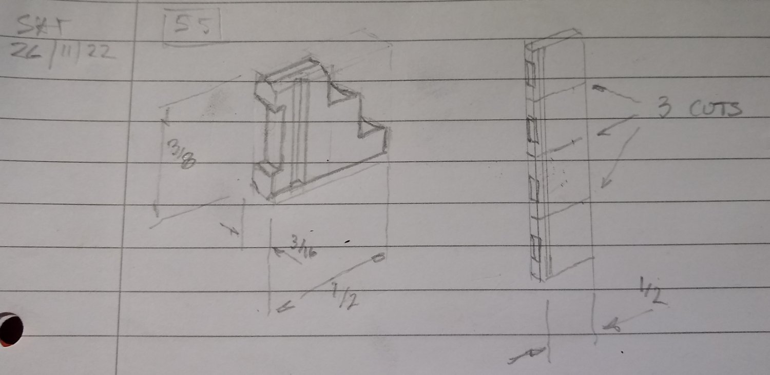
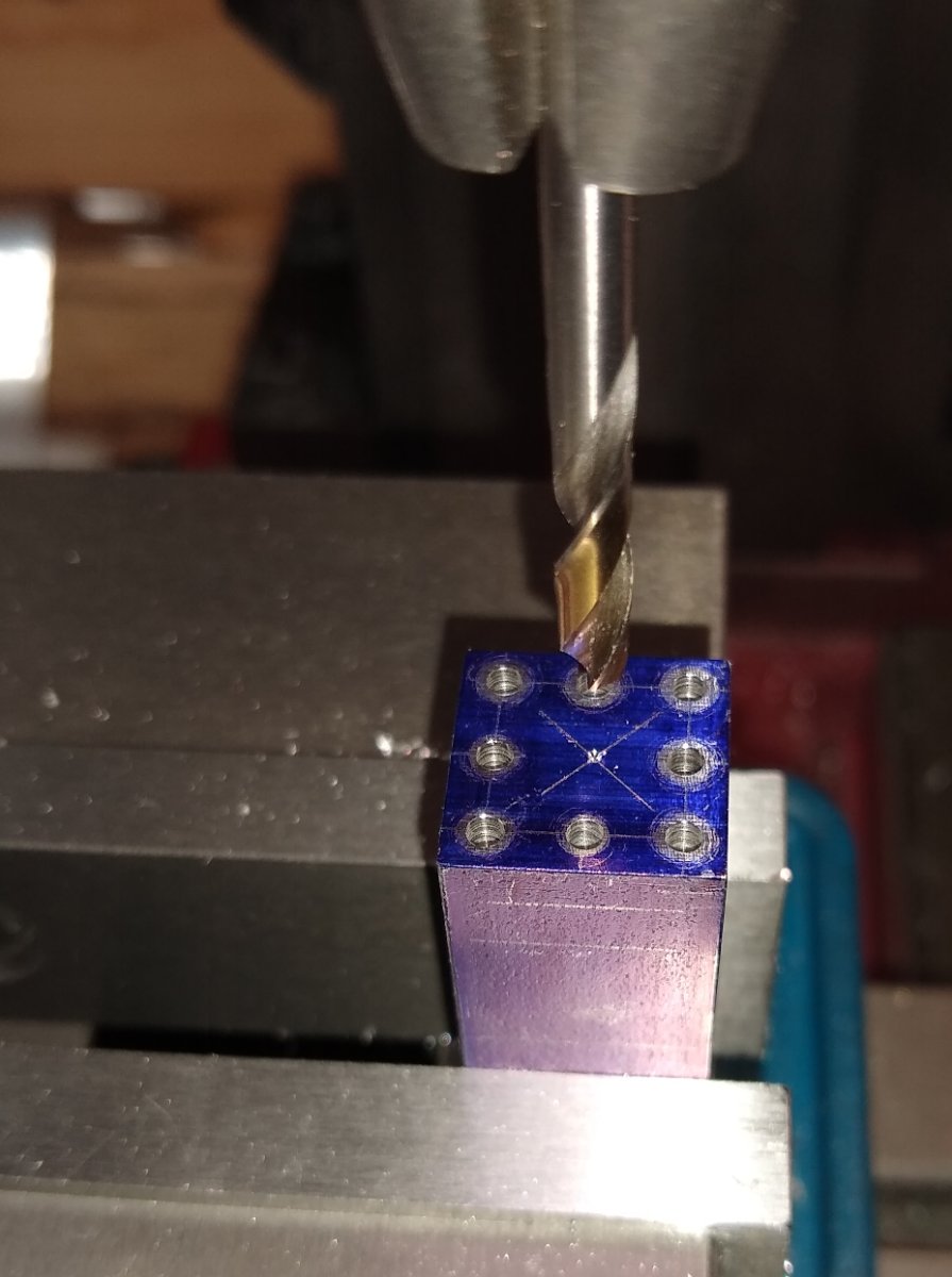
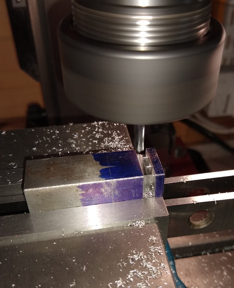
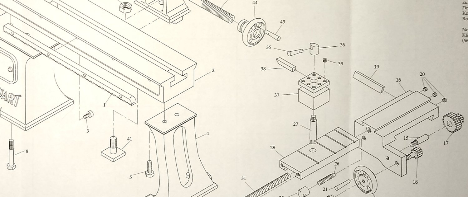
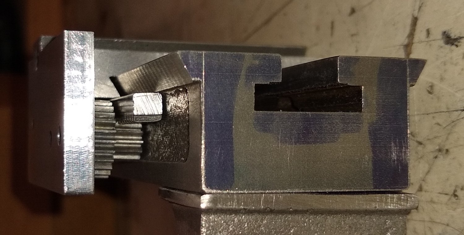
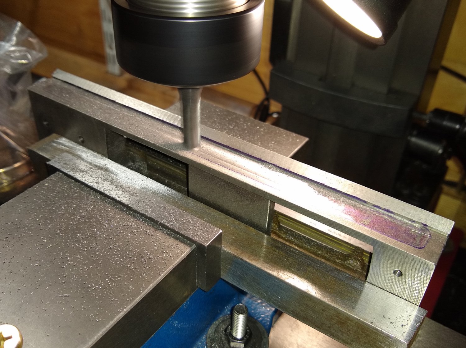
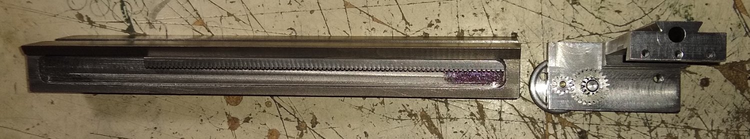
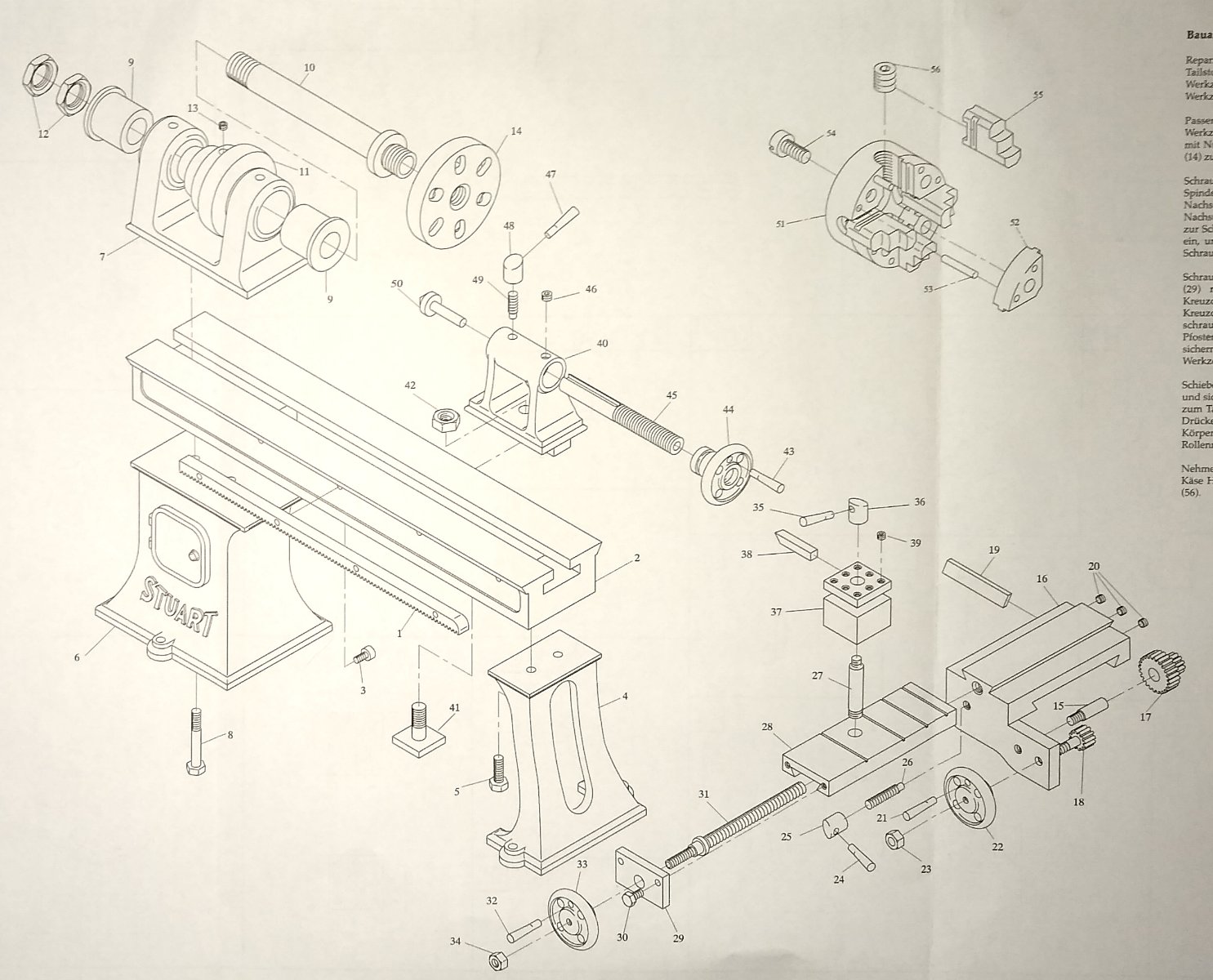
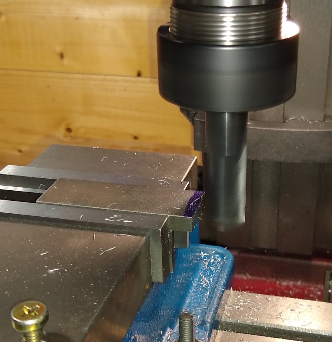
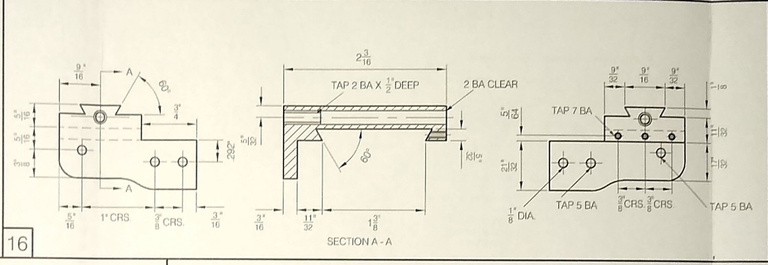
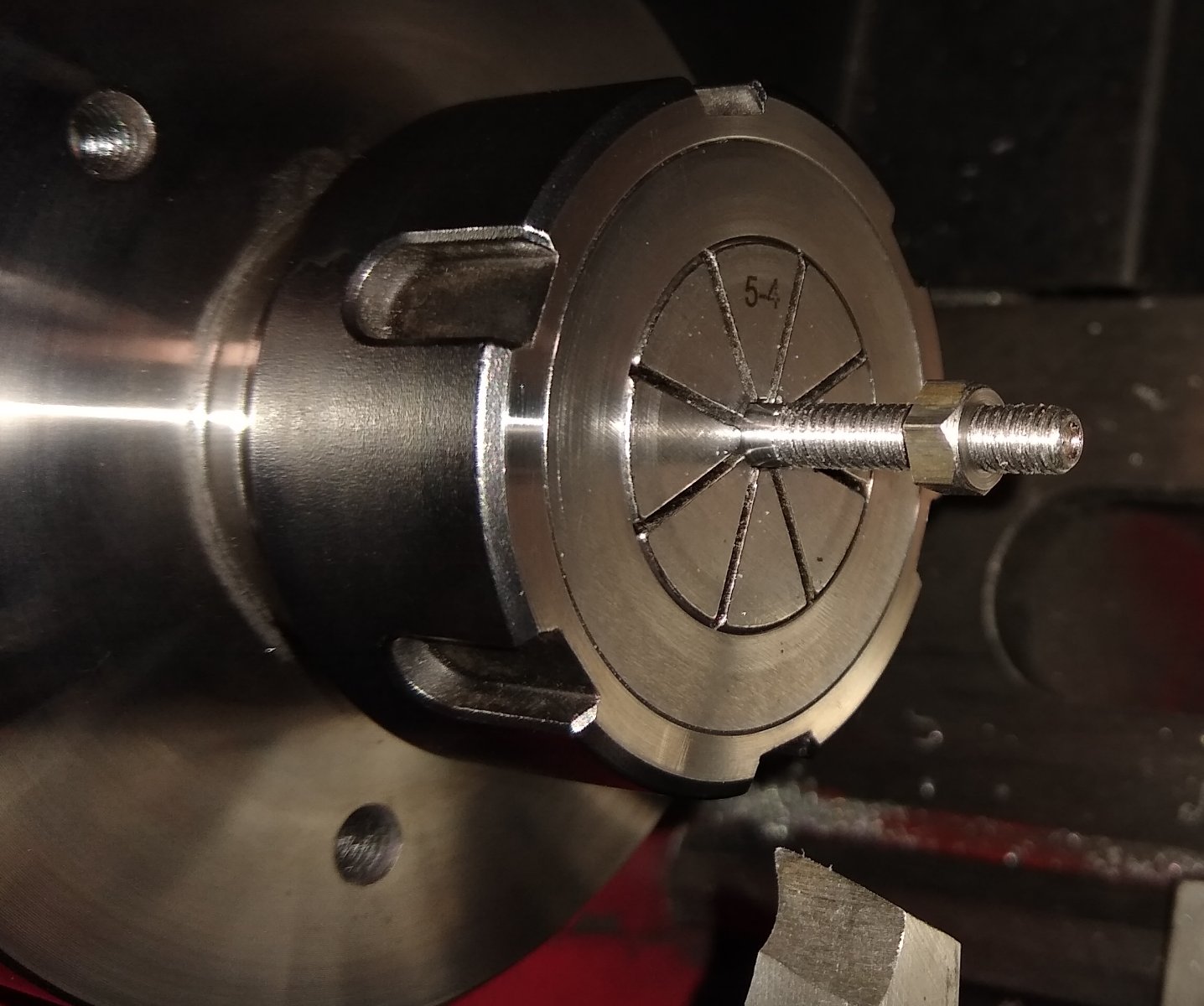
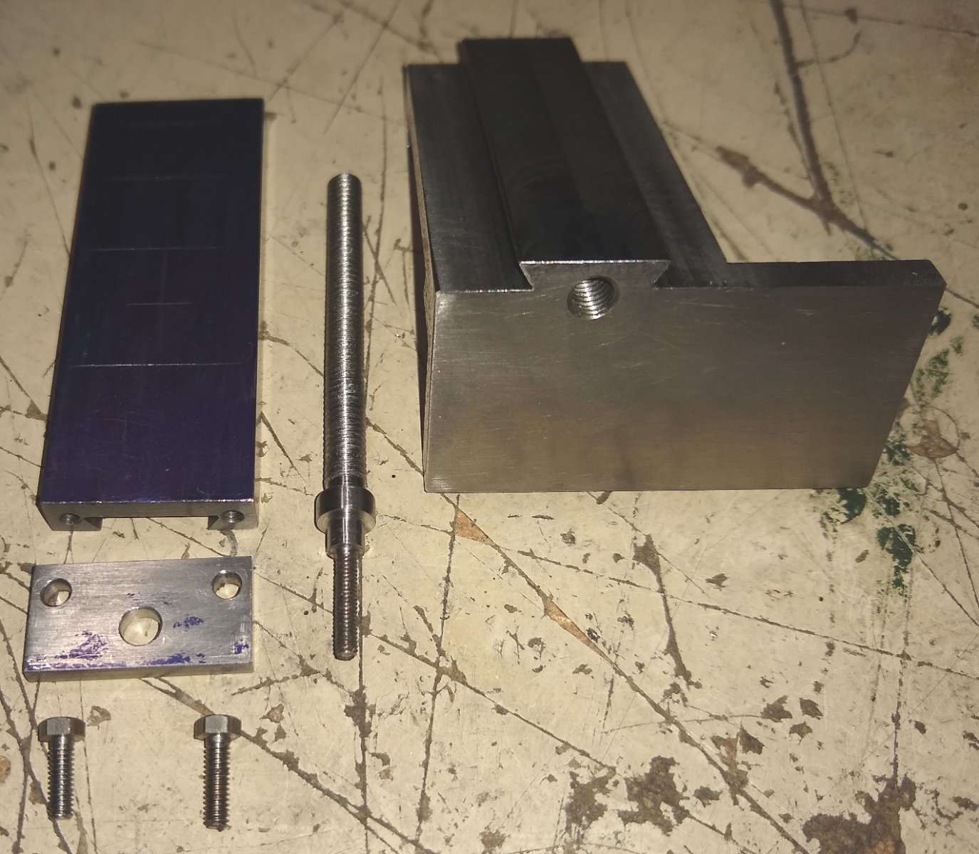
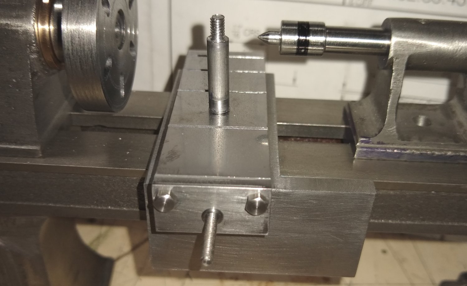
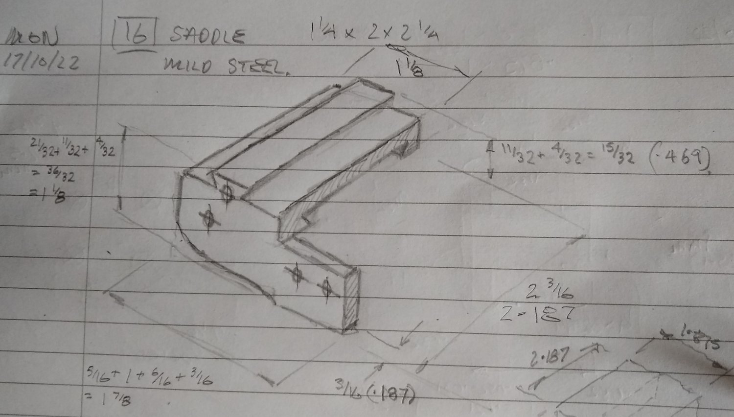
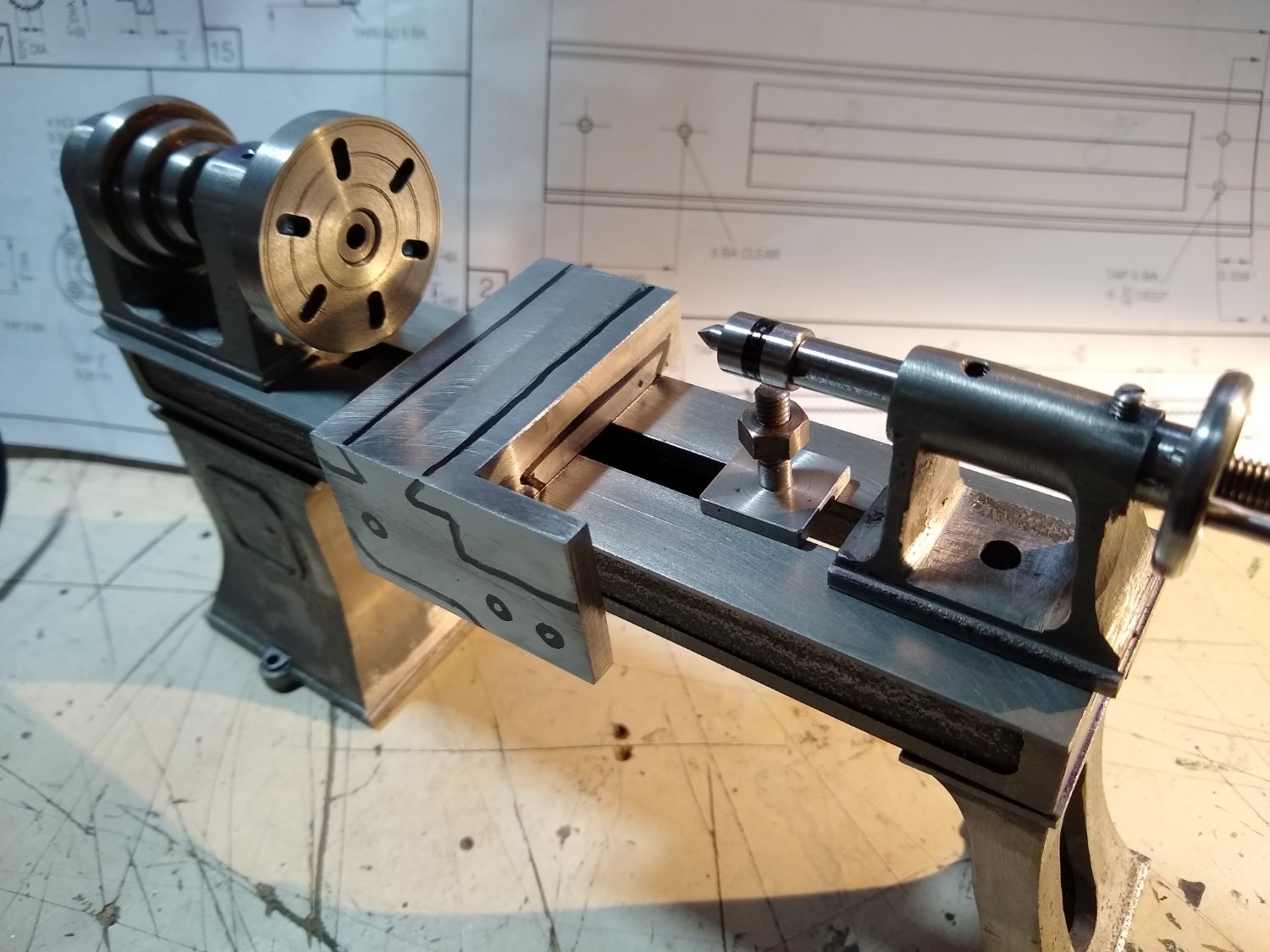
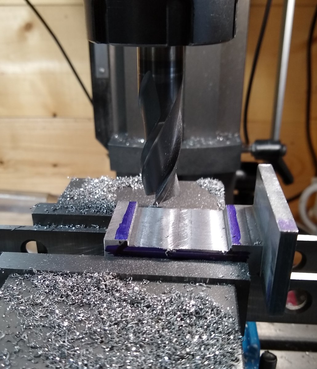
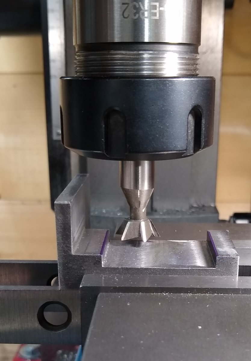
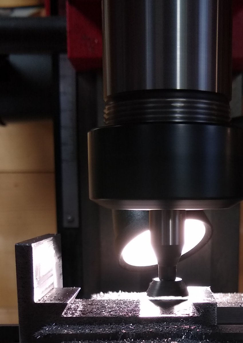
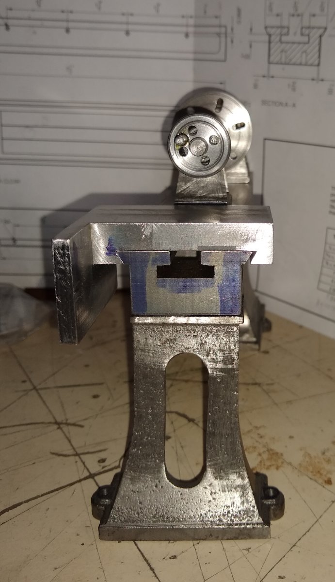
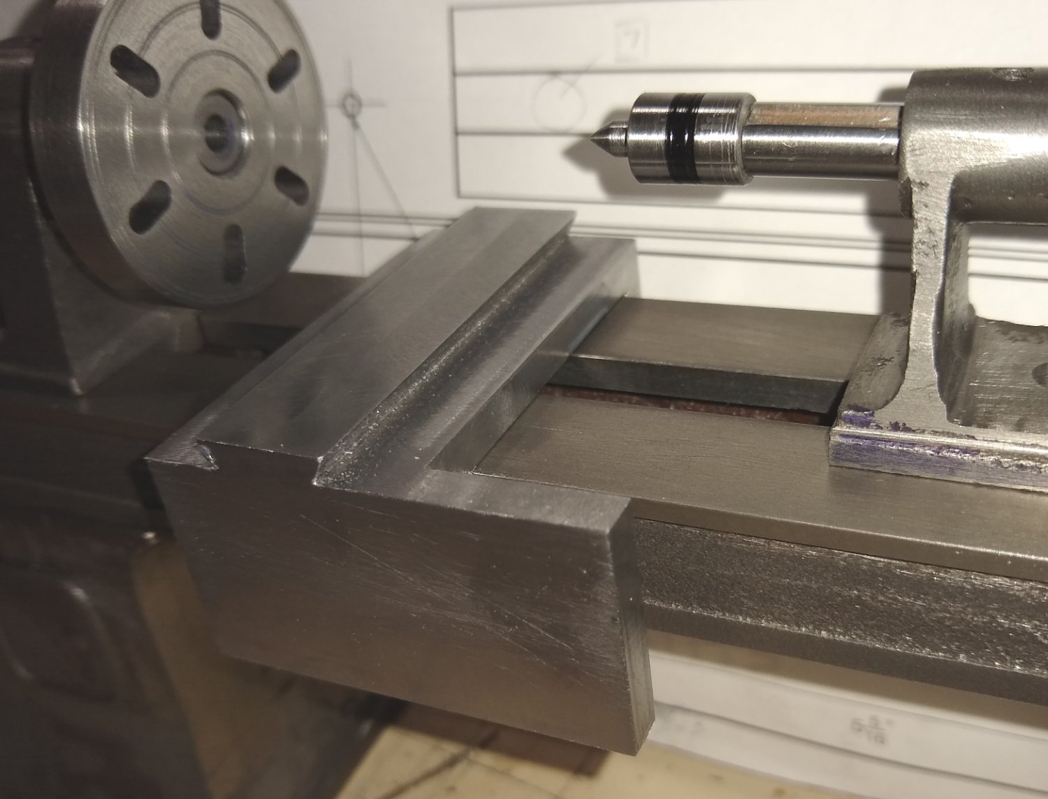
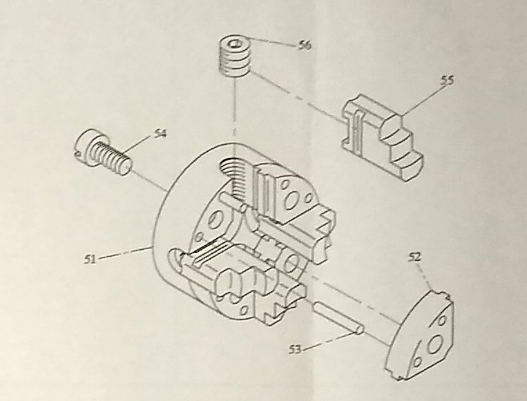
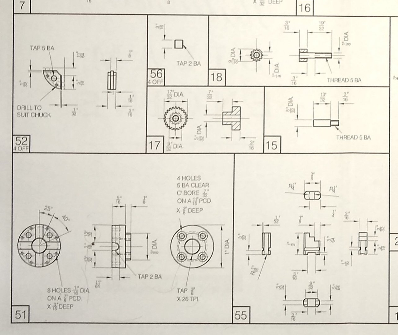
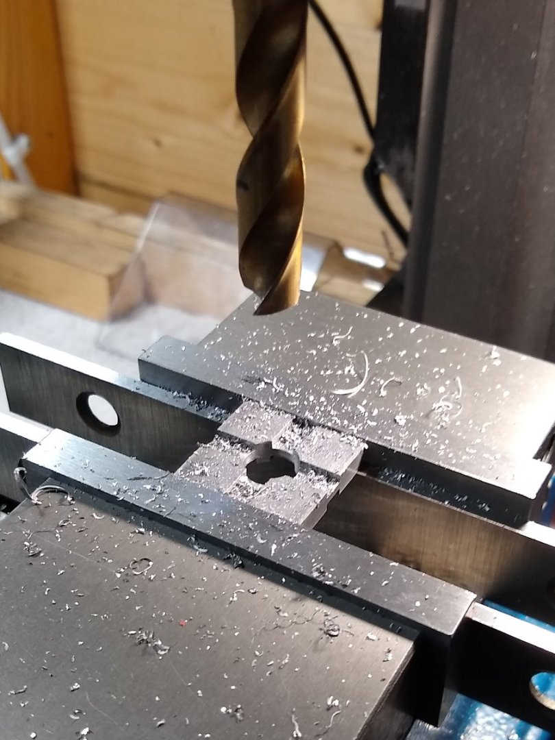
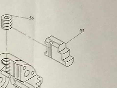
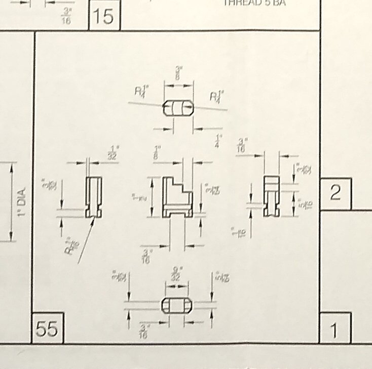
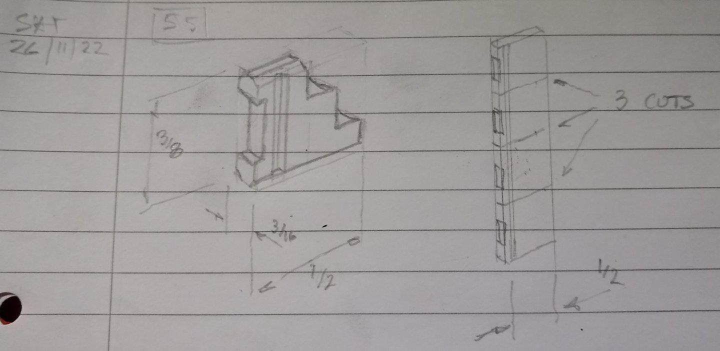
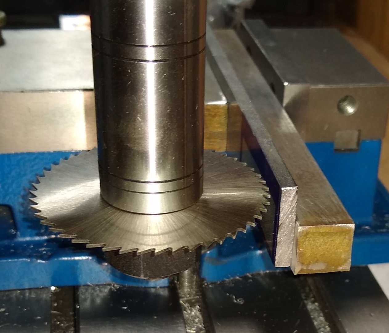
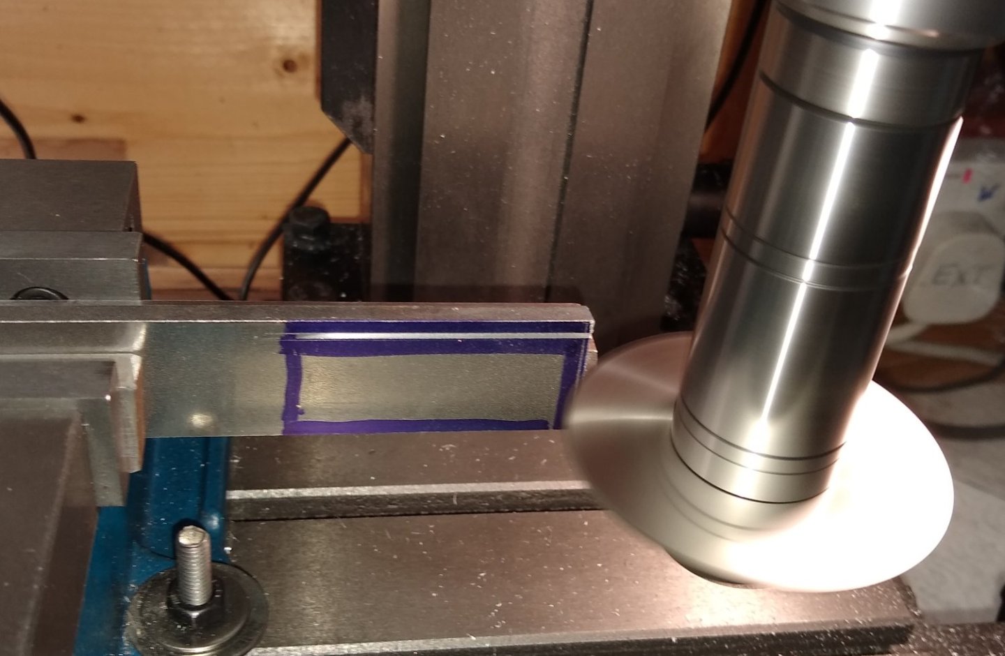
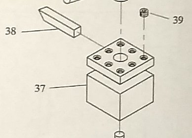
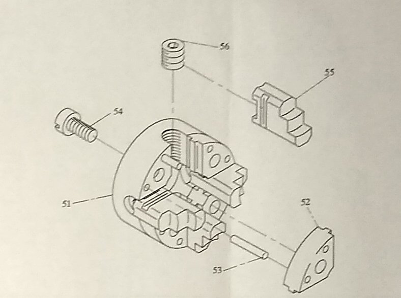
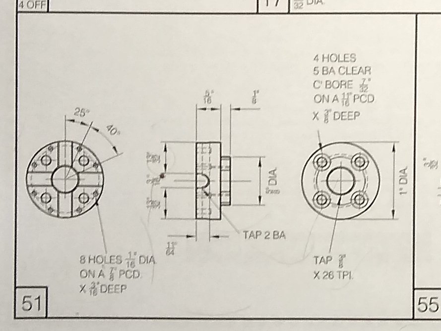
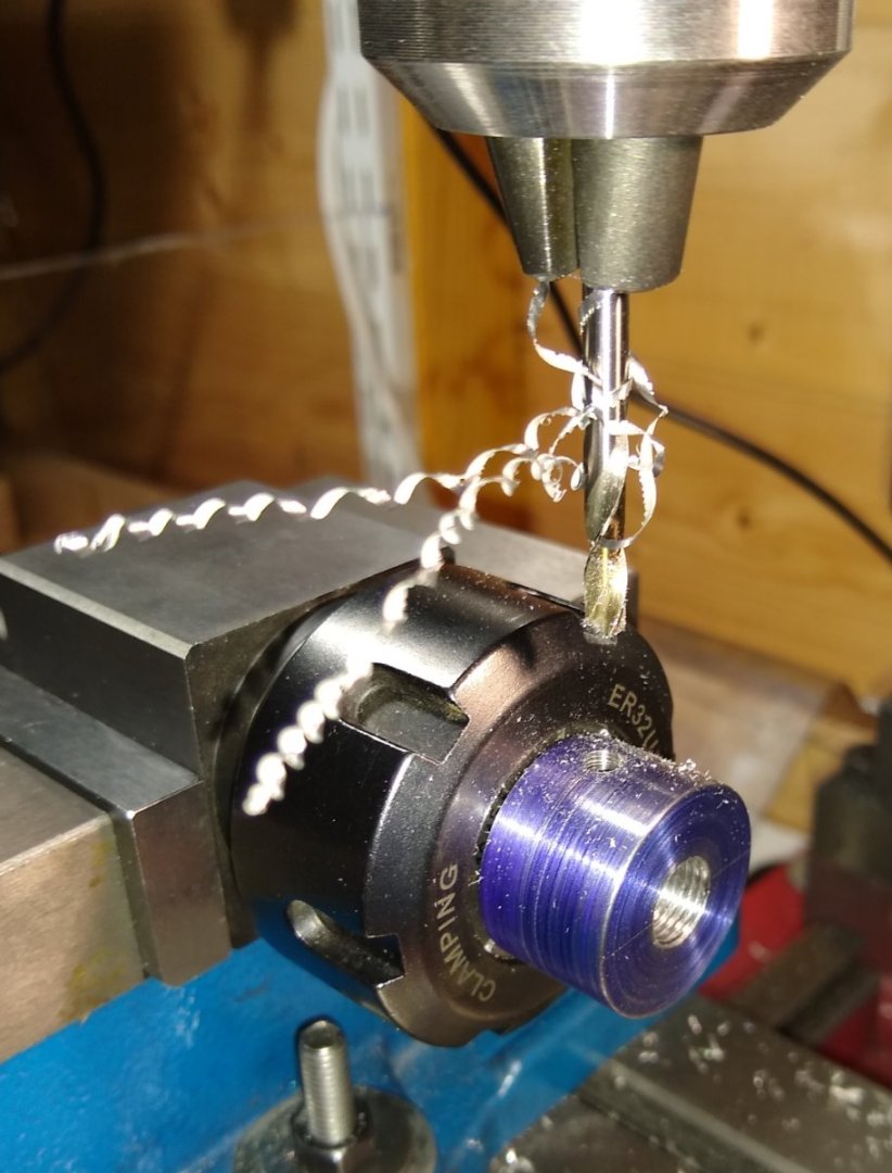
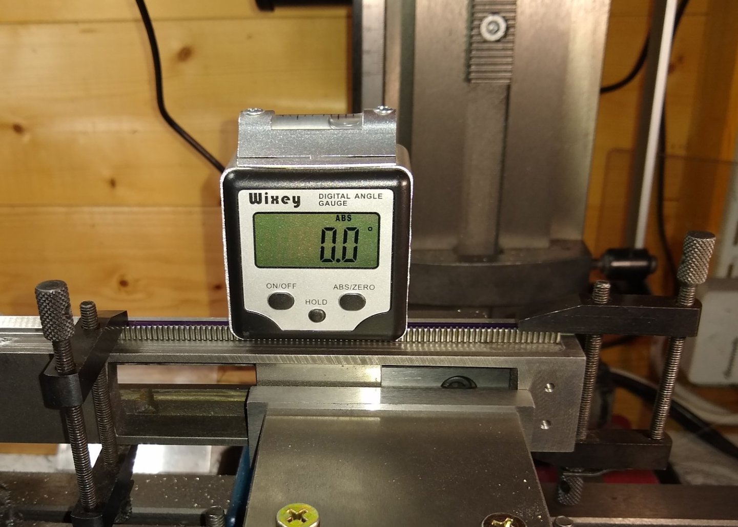
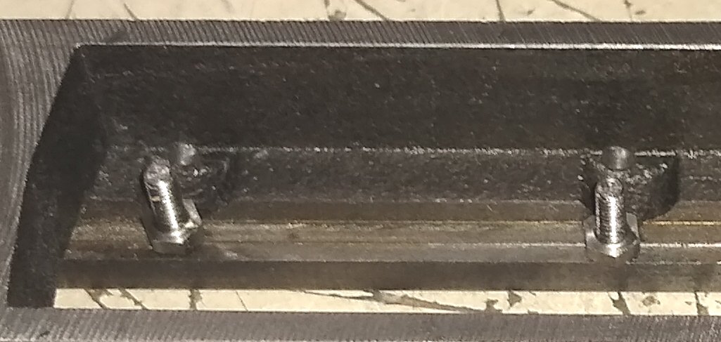
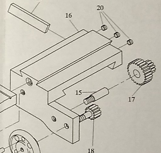
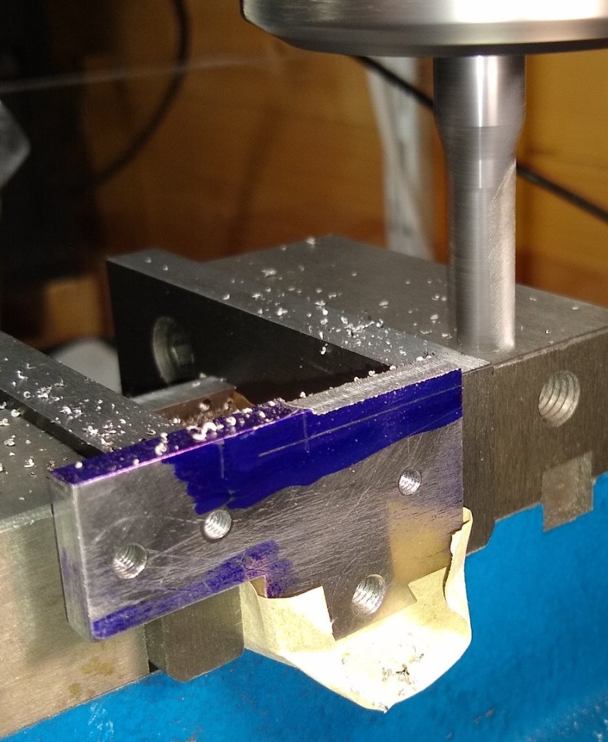
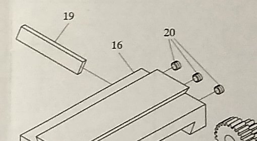
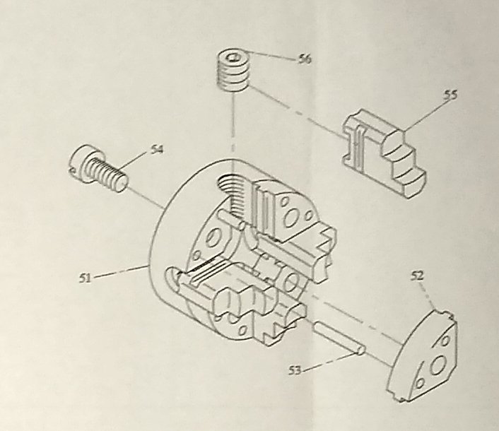
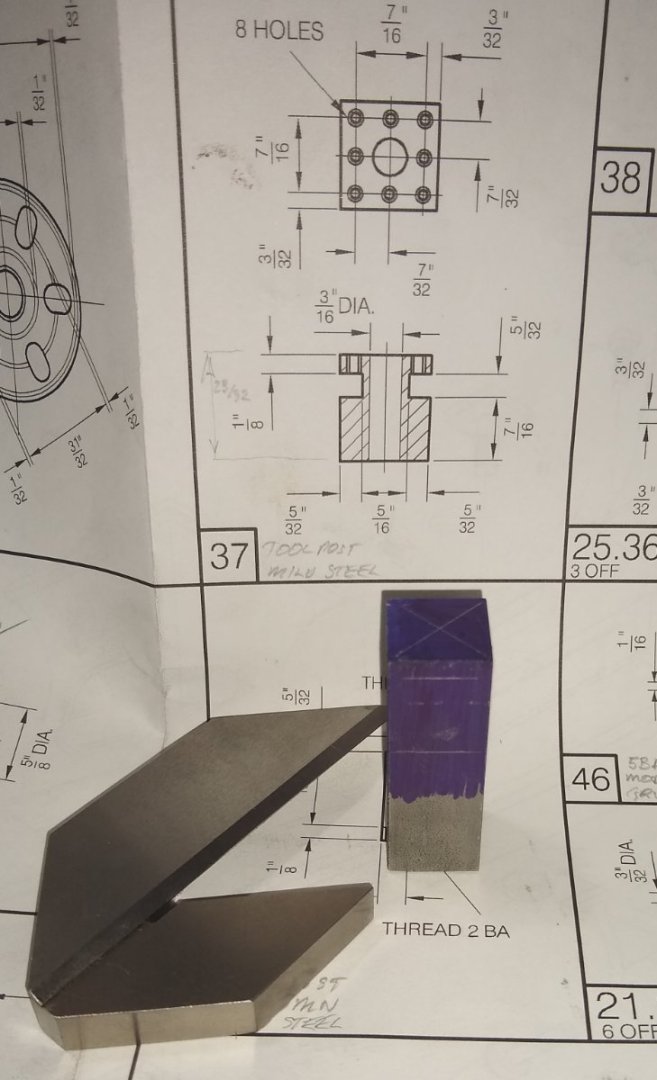
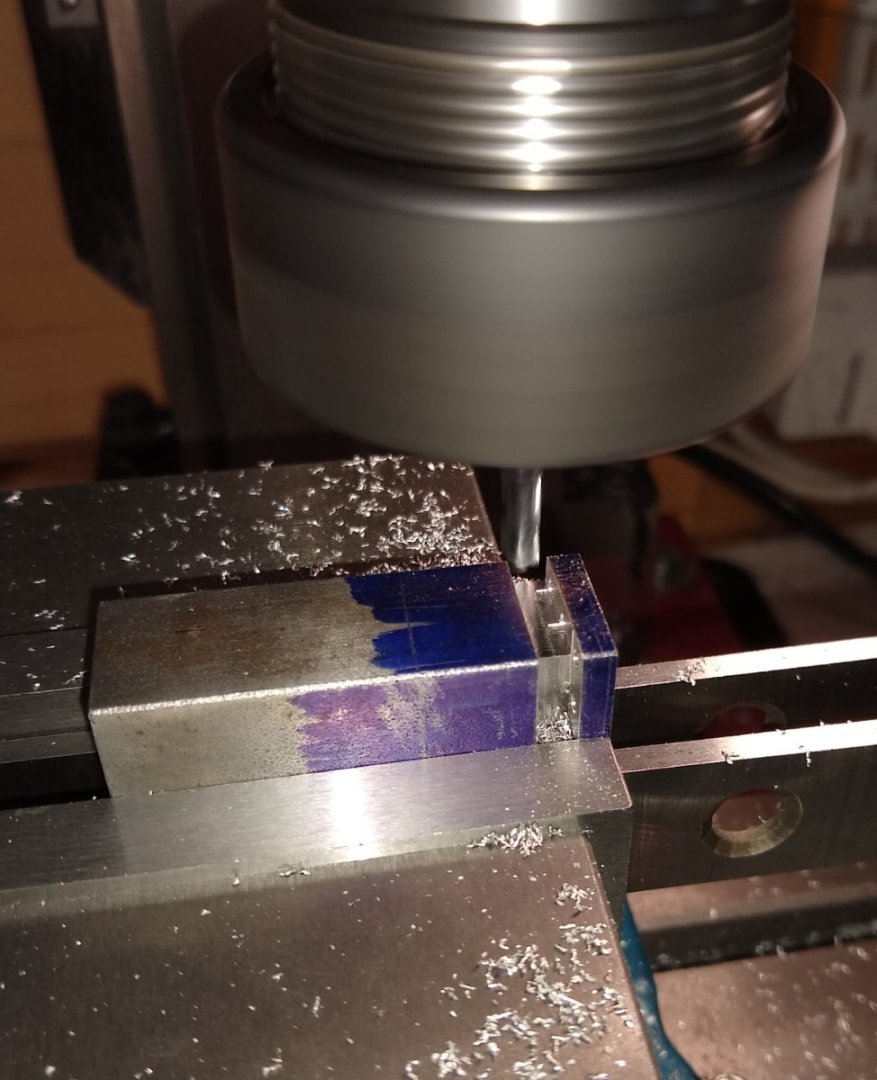
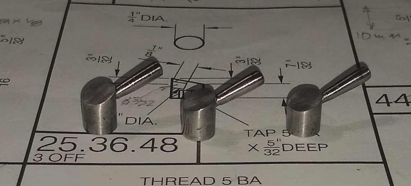
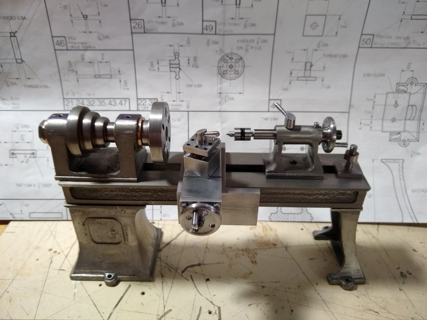
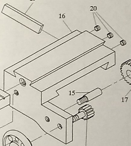
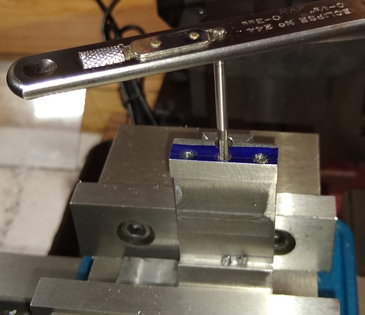
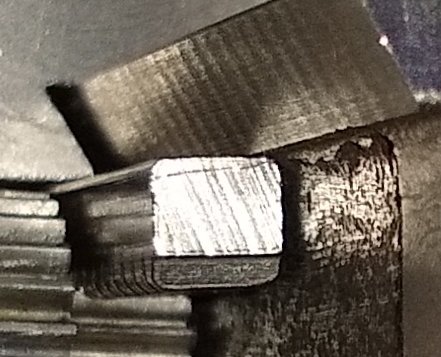
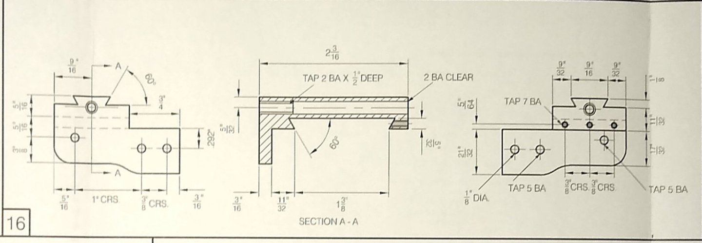
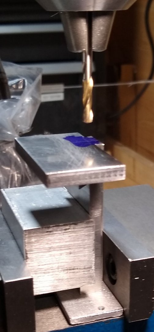
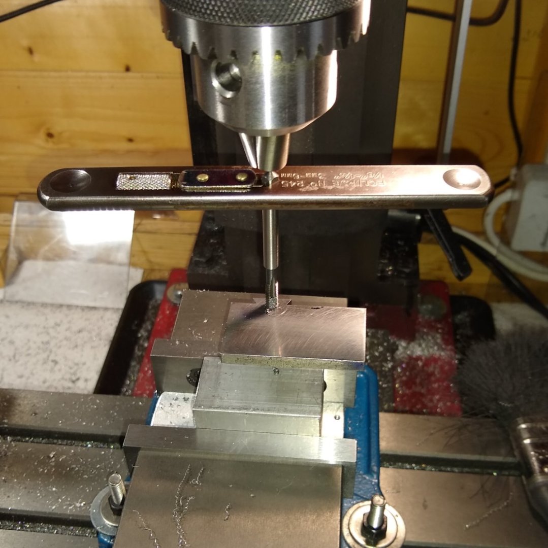
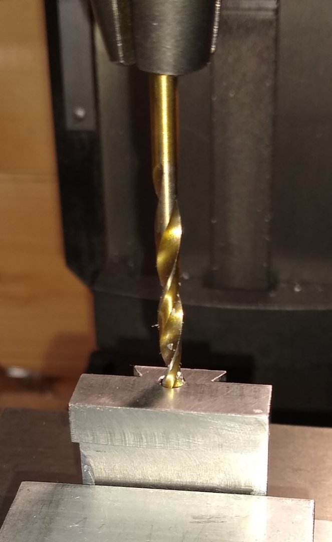
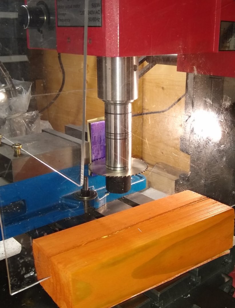
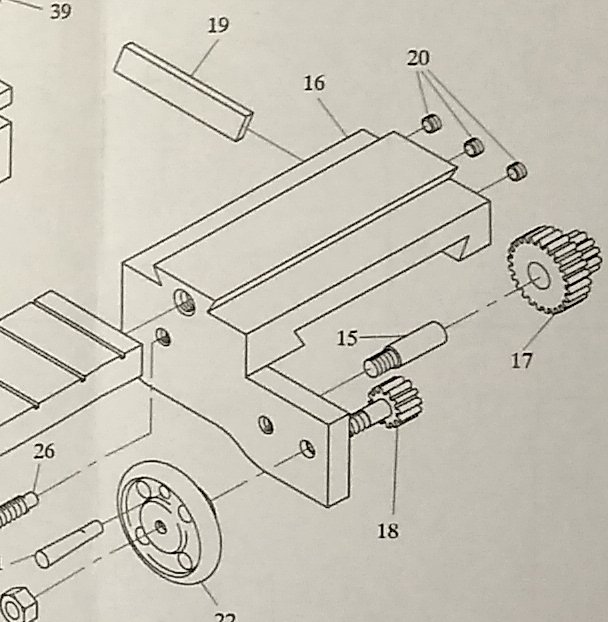
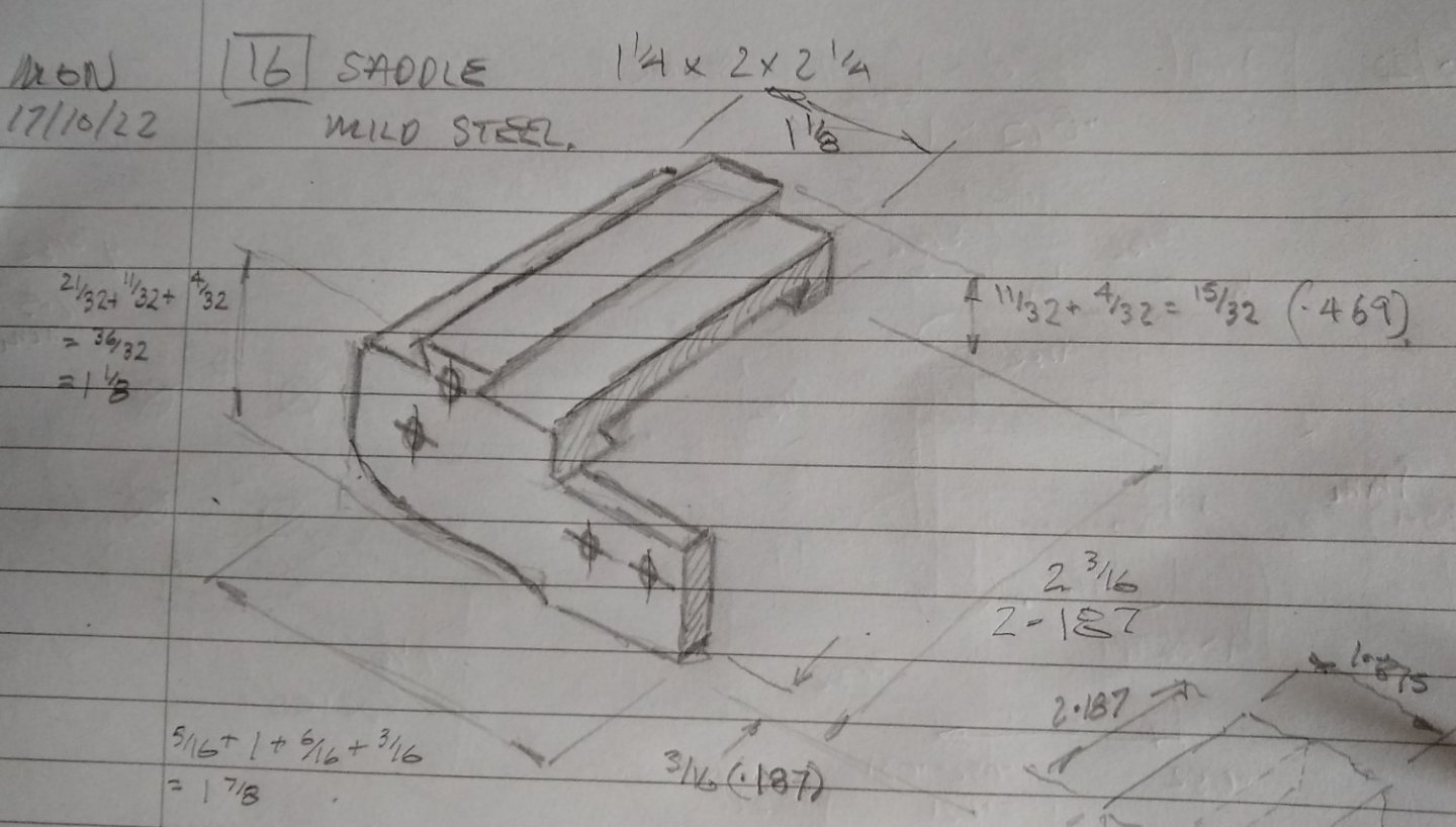
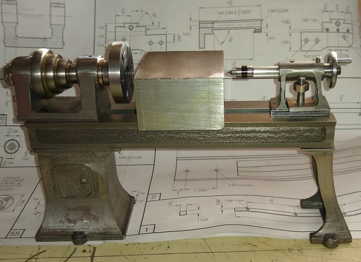
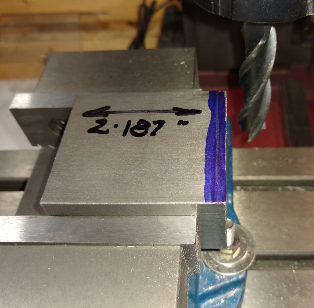
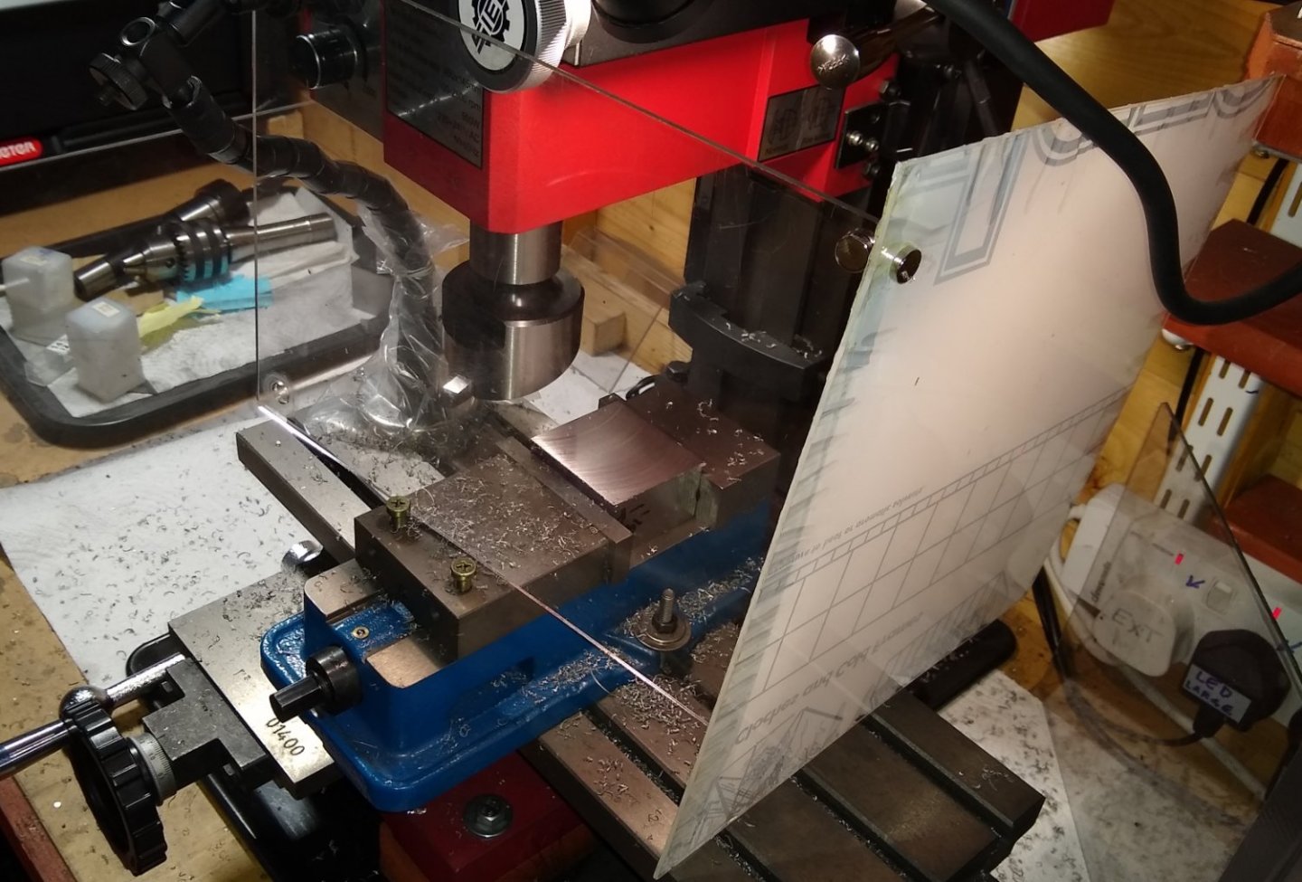
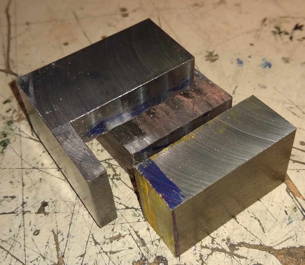
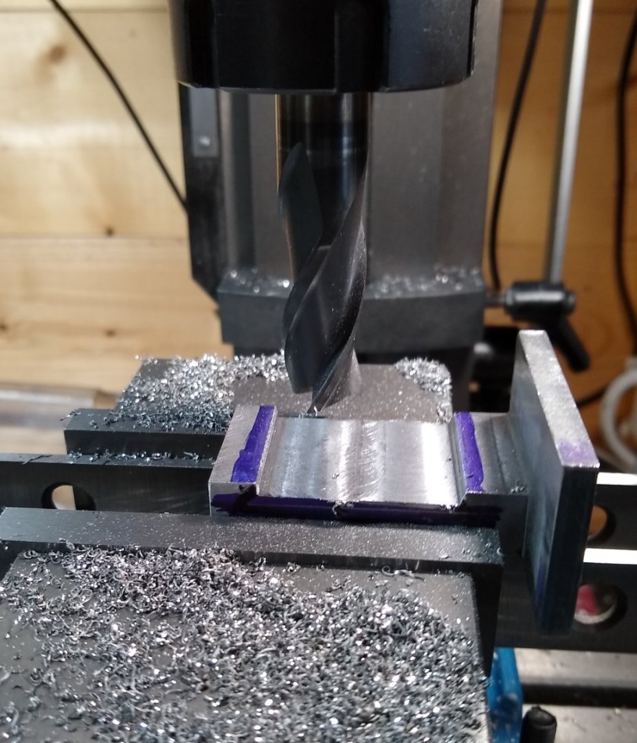
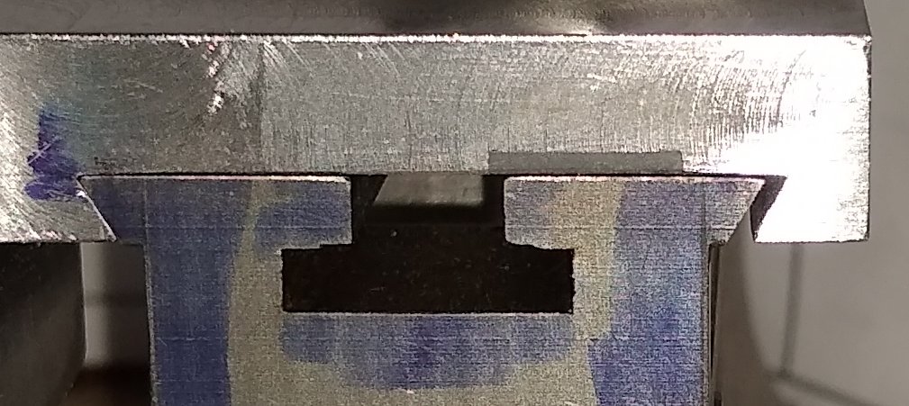
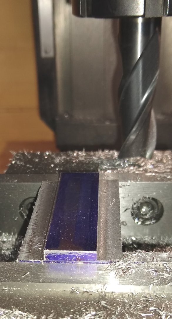
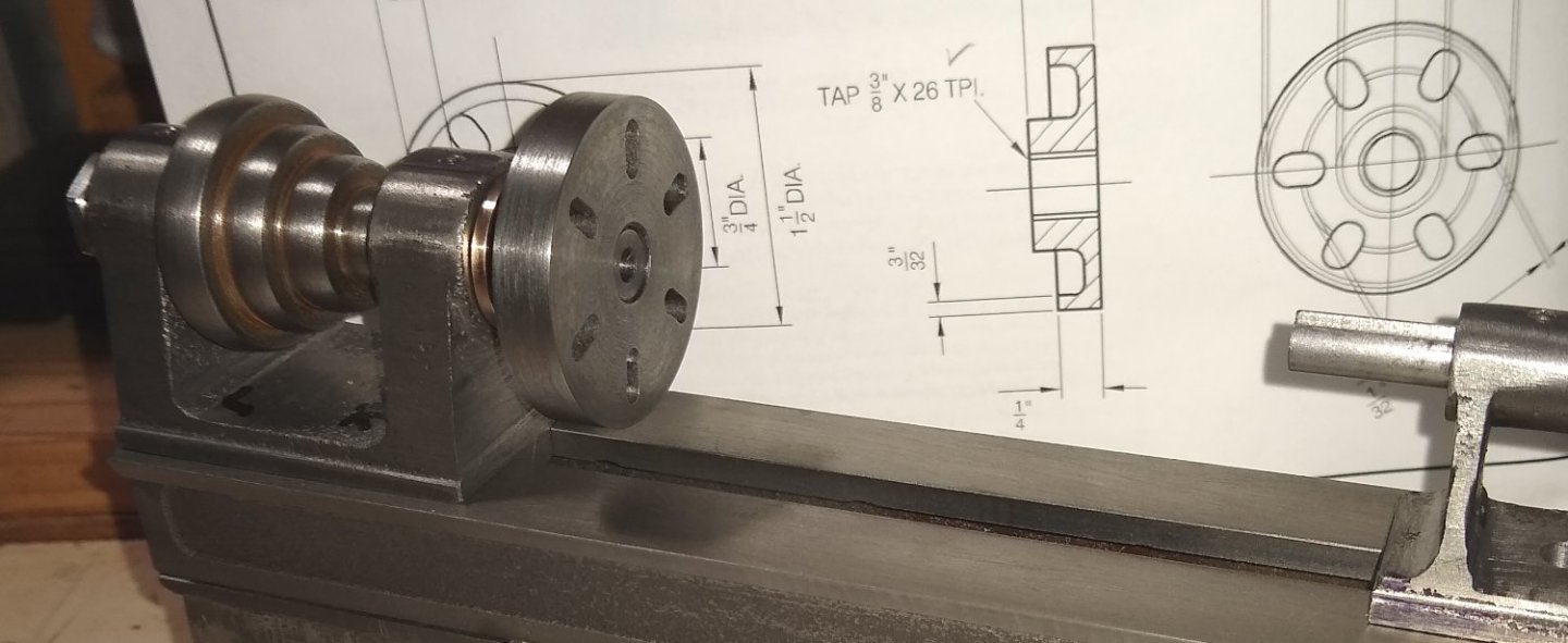
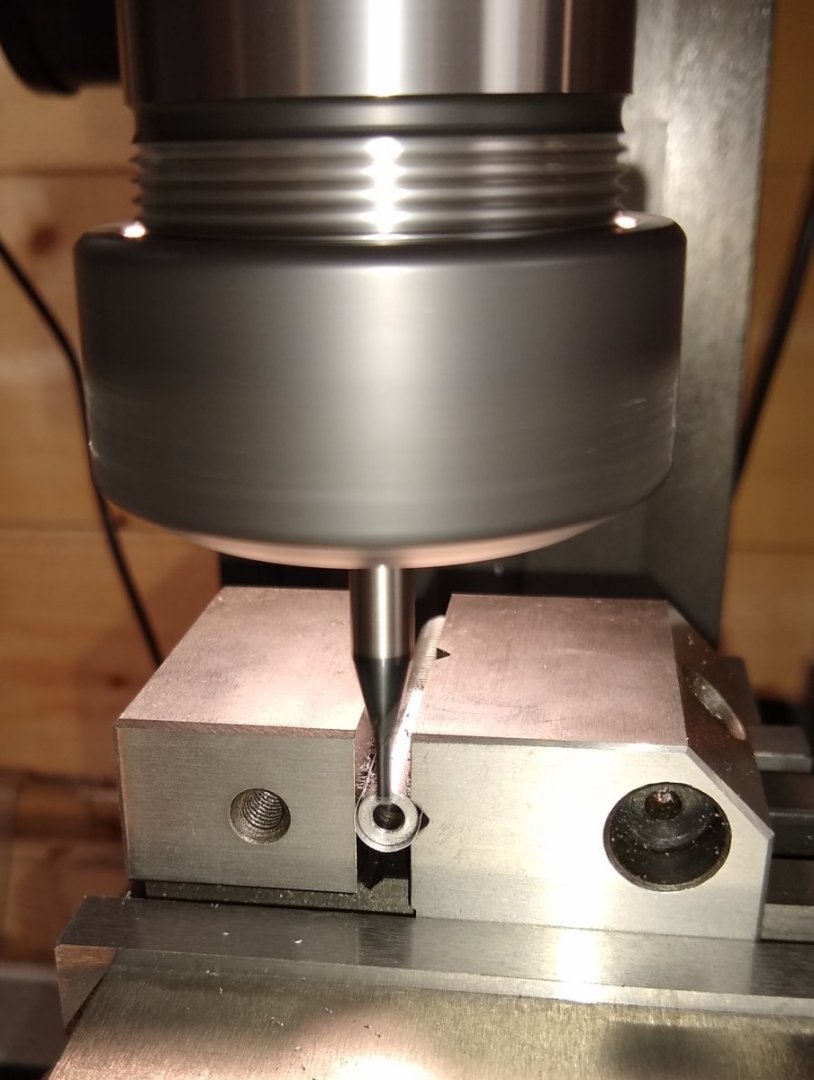
Hi all, A short post to cover some of the chuck activities, before an issue arose. Firstly, lets look at Pt 52, the chuck faces . There are four of these. They are screwed and pinned on to the chuck body. Pt 52 drawing, shown in the top left corner below. As with all these types of jobs the way they are tackled depends on the machinery available and the skills of the machinist. I decided to make the 4x faces out of one single, mild steel, square plate (shown on the right). First, prepare the chuck body to accept the 4x faces ie drill and counterbore the four off 5BA clearance holes. The Anderson blocks don't get much sleep on this project 🙂 Aluminium spacers used to lift the chuck away from the collet for when the drill broke through. Counterboring the holes. The drilled and c'bored chuck body. This was all reasonably plain sailing. Now the attention turns to the chuck face faces. To produce the 1/16" wide x 1/32" deep guides on the two edges of each chuck face, I firstly cut 3/16" wide channels x 1/16" deep on each side of the 3/16" thick plate. Then drilled the 3/8" diameter hole for spindle clearance. Using toomakers' clamps to spot through the chuck body 5BA holes onto the square plate. I don't have X&Y Digital Read Outs, or trust the tumblers on those axis to drill the parts independently. Edit: I will return to the completion of the chuck faces in a later post. I wanted to at least makes the grooves in Pt 55 (the Jawas) since they would be a sliding fit between the chuck faces. But now on to Pt 55, the four chuck jaws. Dimensions below. A sketch I made to help get my head round the best way to make these parts - there were lots of such sketches made. Basically, I'm trying to figure out the optimum order to machine the features, bearing in mind machining one feature (eg the steps) may remove work holding material for a later step. I decided to first machine the 1/16" x 1/32" slot that would mate with the chuck face. I would do this using a 1.5mm slitting saw. The only problem with that was that the slitting saw holder has a large deep nut on it's underside that would clash with the vice top. I had already replaced the Stuart supplied 3/8" deep bar with 1 1/2" deep bar (from my stock) that I hoped would allow me to machine above the centre of the vice. But not even 1 1/2" took me high enough above the vice. So I tried moving the bar out to the side braced by a large section tool steel bar. I managed to make the beginnings of a slot with the material out to one side of the vice, but it soon became apparent that the slot was deeper closer to the vice than at the other end which was 'flapping in the breeze'. So I pulled the plug and ordered a 12" length of 1 1/2" (Edit: 2 1/2") x 3/16" bar. This would allow me to machine the slot over the middle of the vice and be more firmly gripped with the vice jaws. The material took over a week to arrive, so I'll continue in the next post. All for now, Richard


-
A big 'like' for the cat ...and the boat 🙂 Richard
- 156 replies
-
- 1
-

-
- marisstella
- marisstella model ship kits
- (and 4 more)
-
threaded mount does not give concentricity, Yes, there can be a number of things wrong with an imperfect thread ie not concentric, bent, under size etc. So for true location the chuck does need to be accurately registered, and rely on the thread only for pulling the chuck home. As I'd like to eventually run the Stuart lathe from a 10V engine and turn some material, brass or nylon, it would be better if the faceplate and 4 jaw chuck is properly registered. I'll investigate the feasibility of this. Richard
-
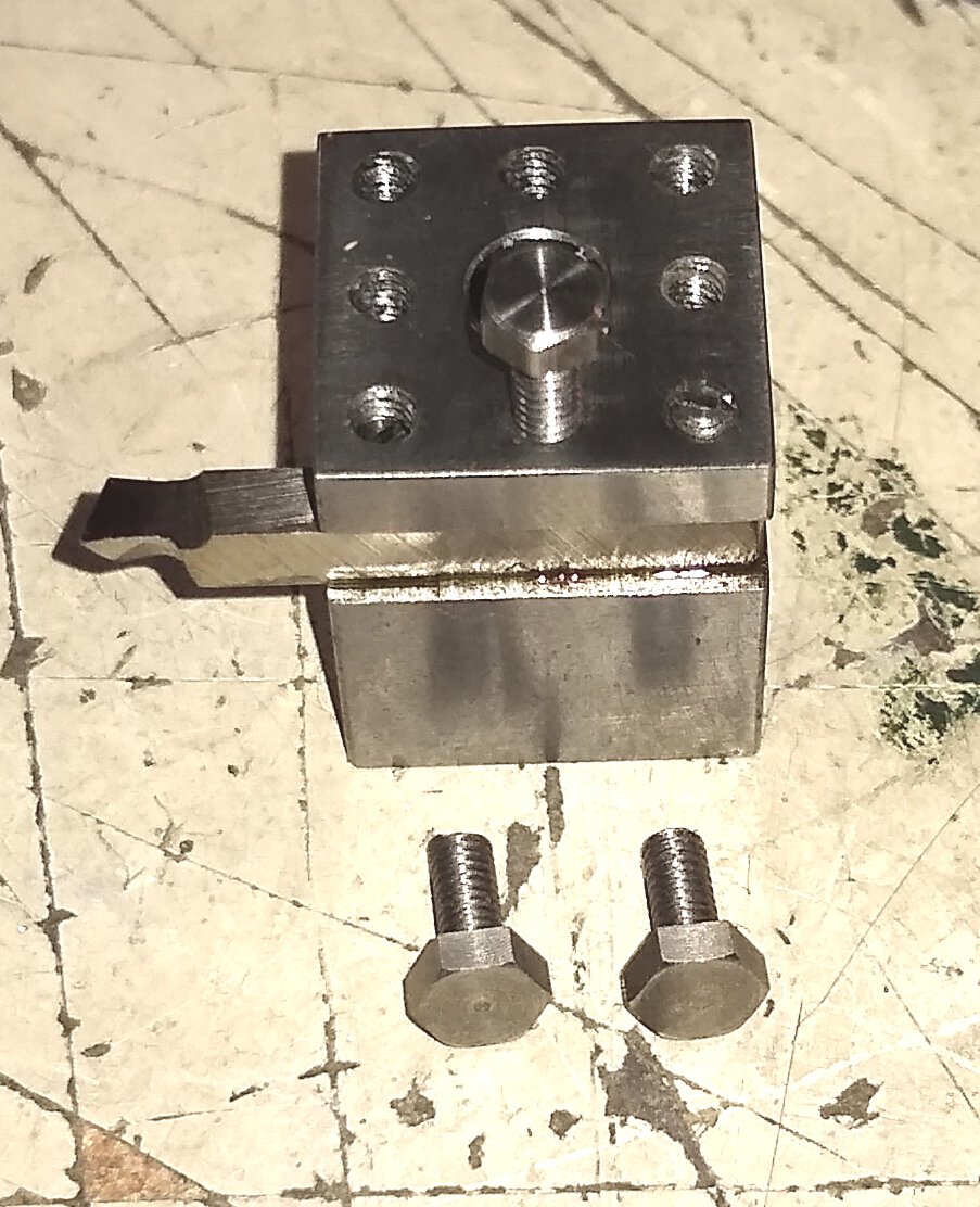
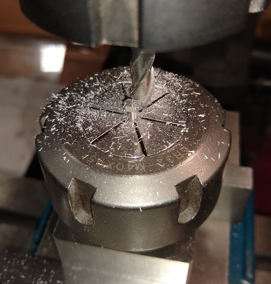
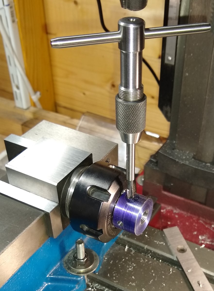
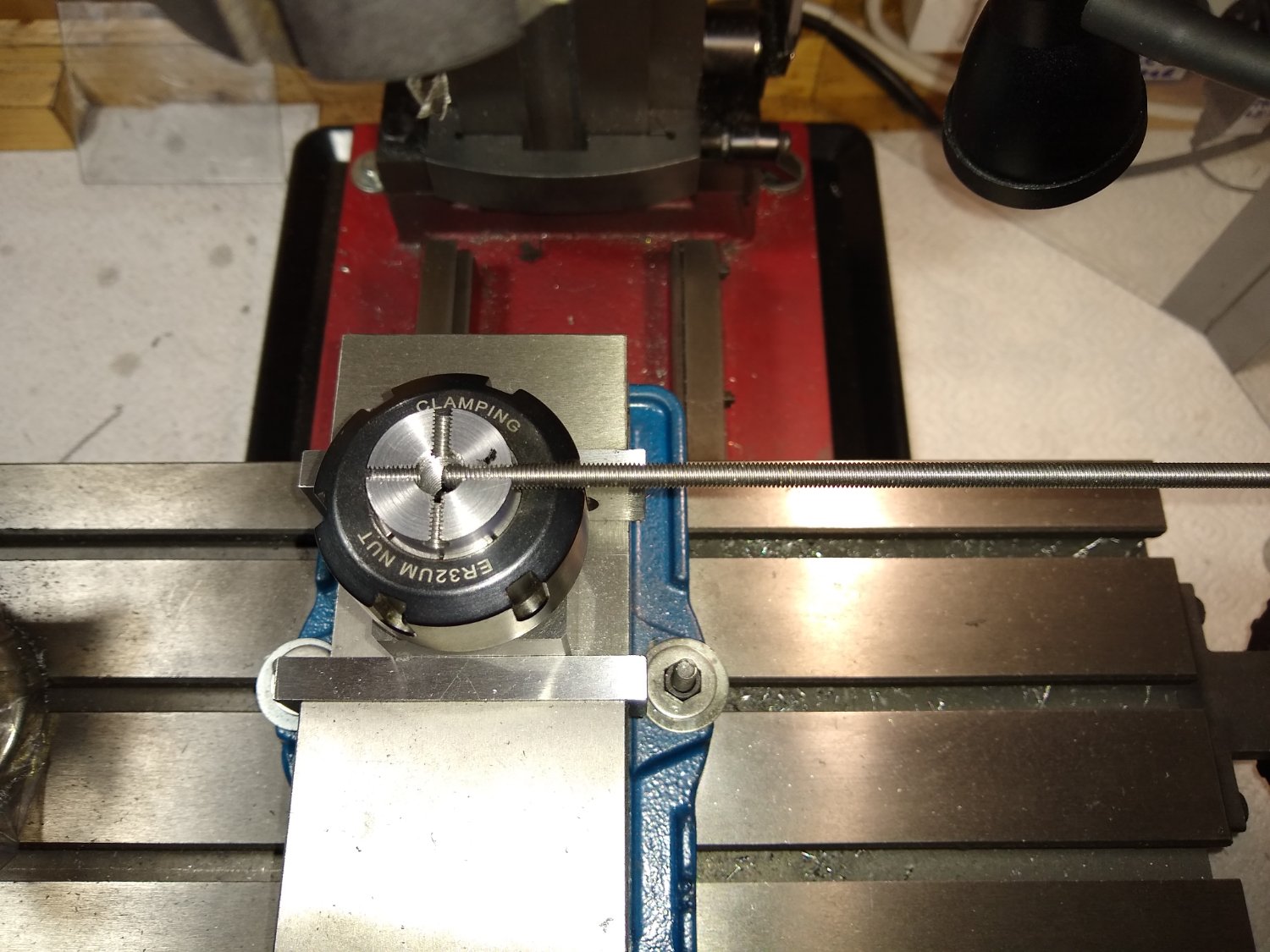
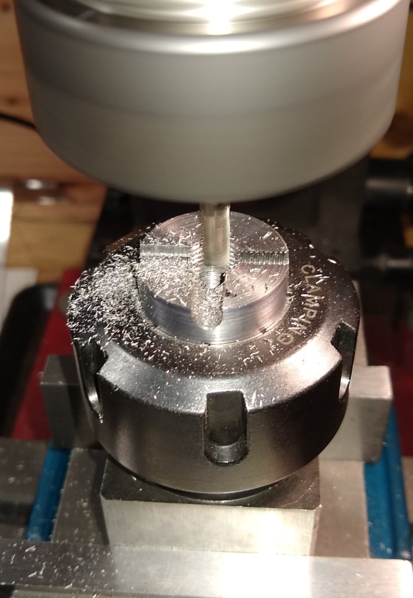
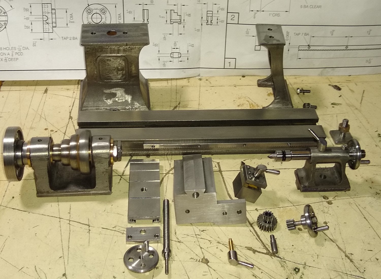
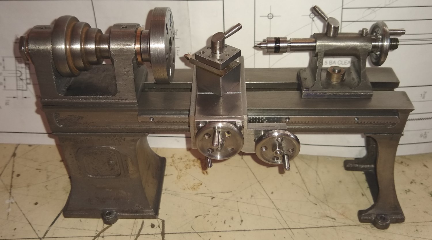
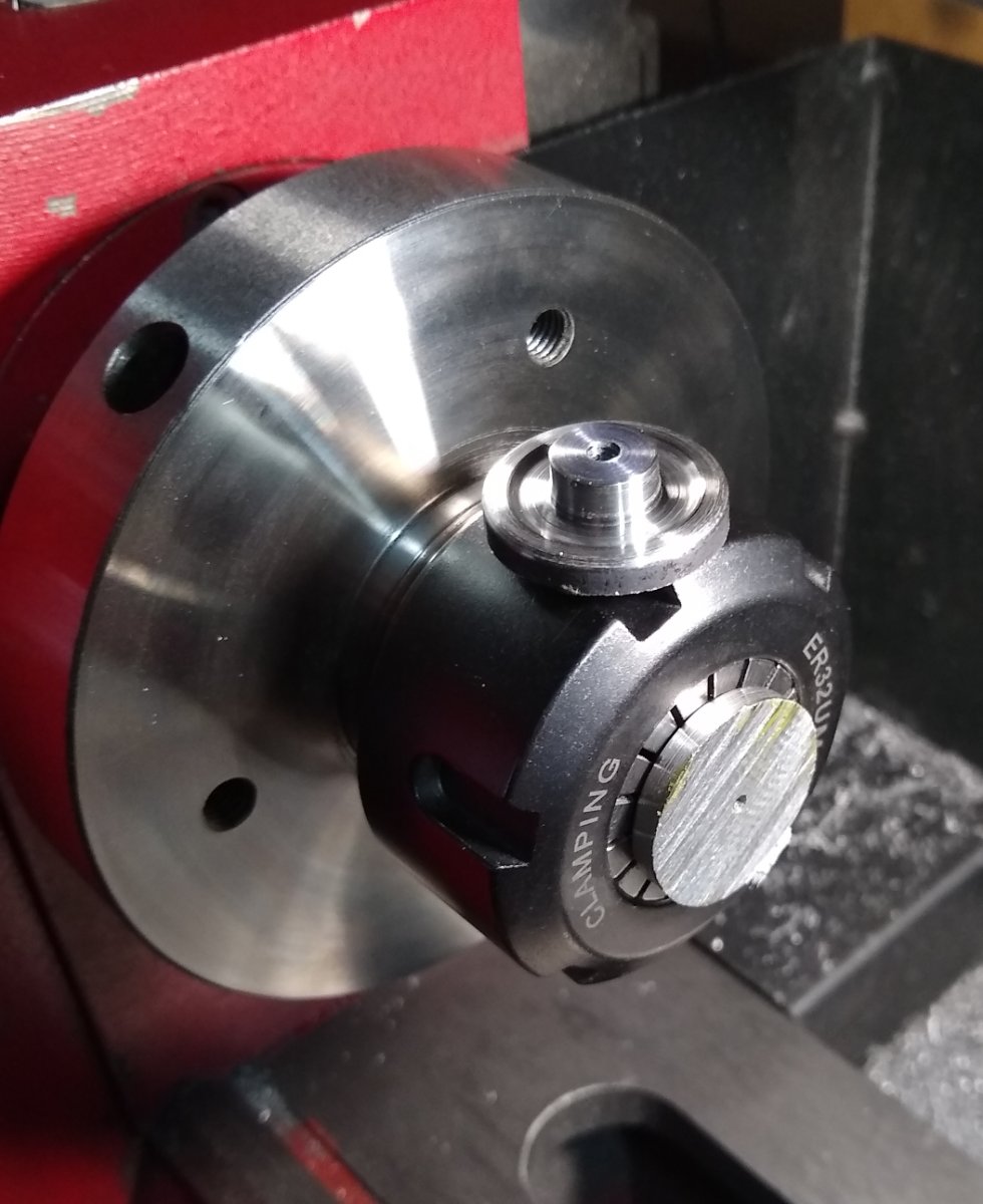
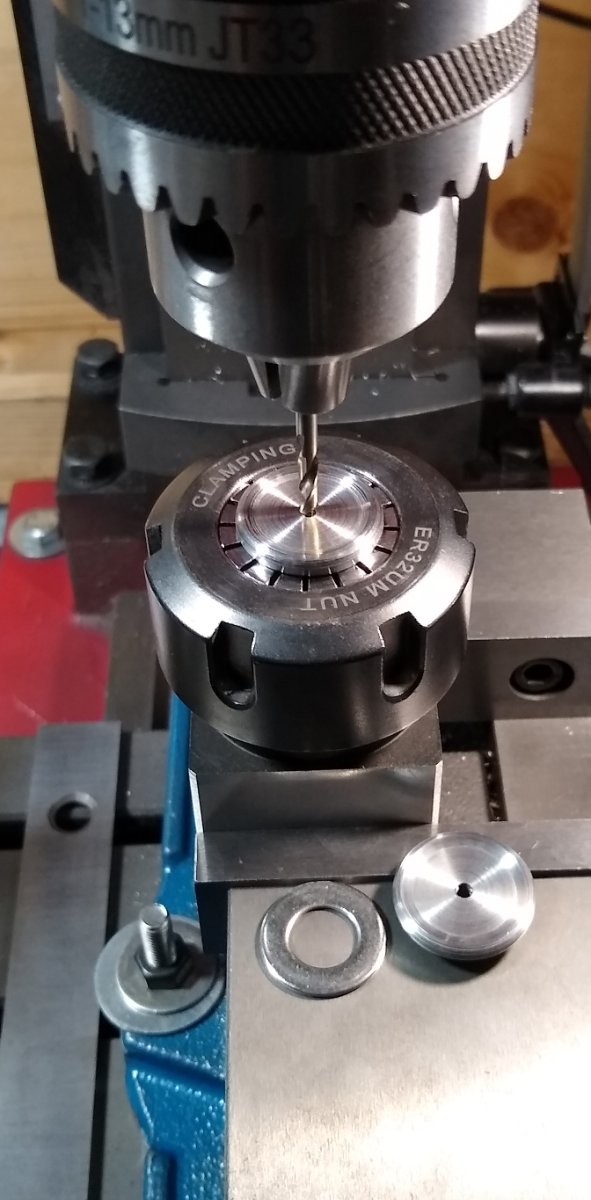
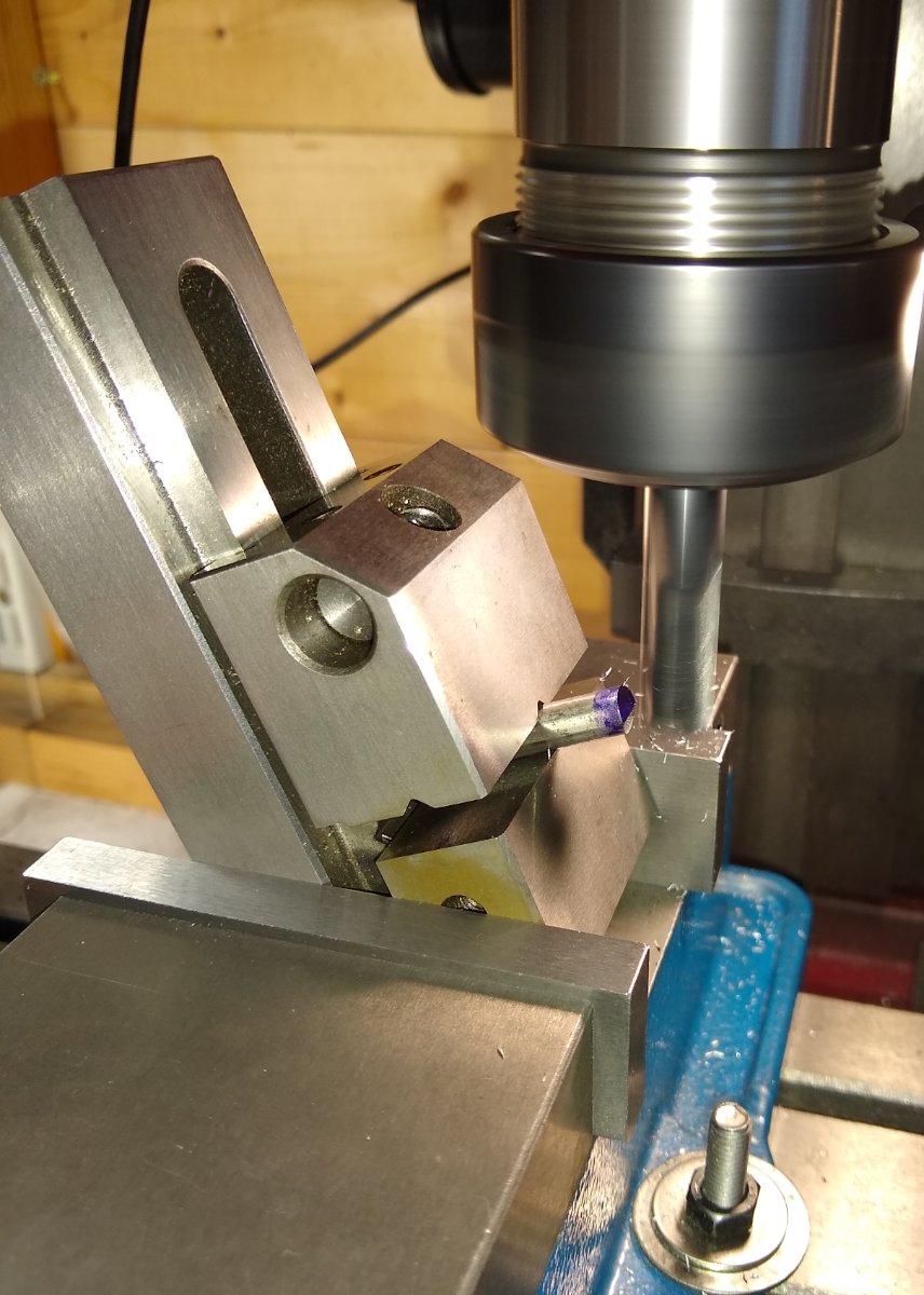
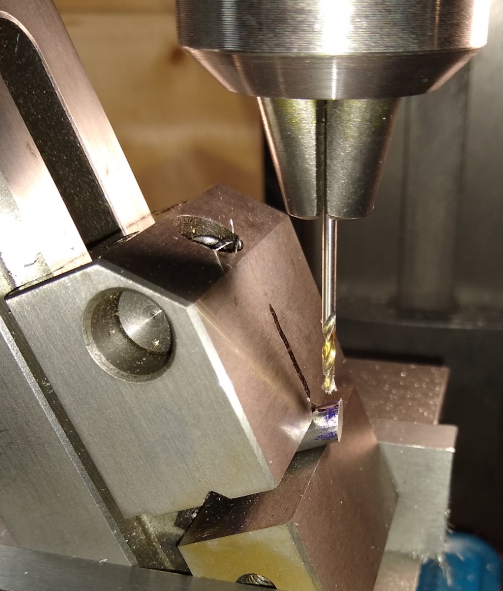
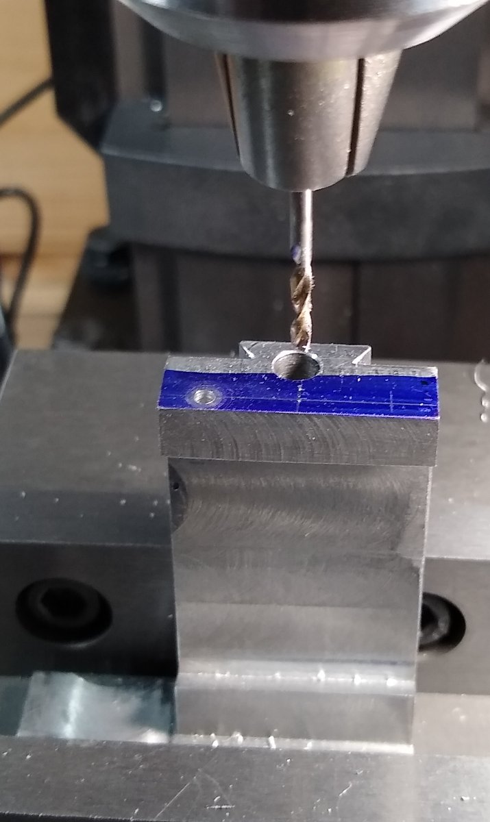
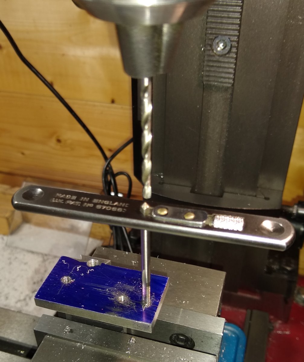
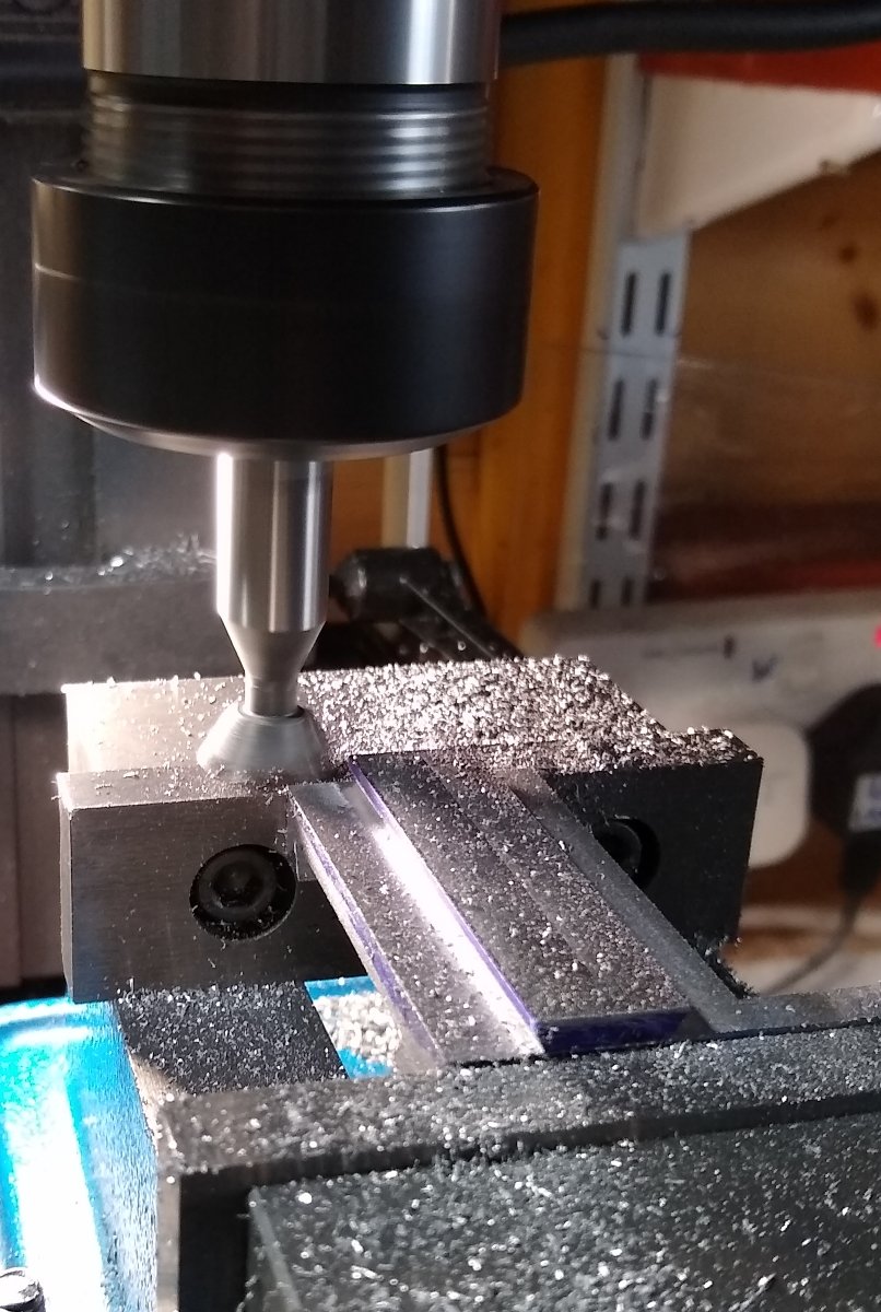
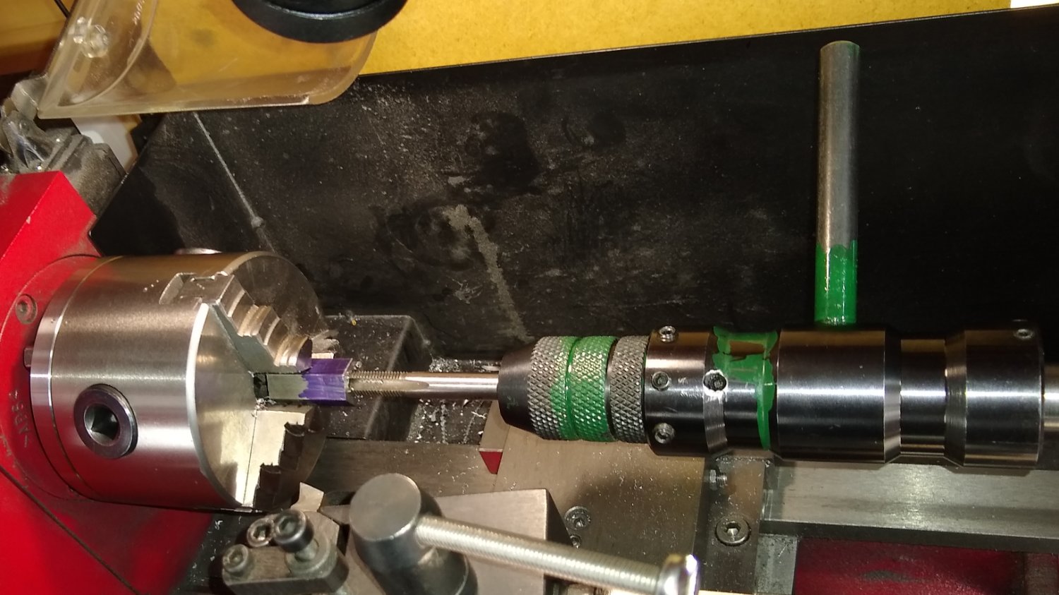
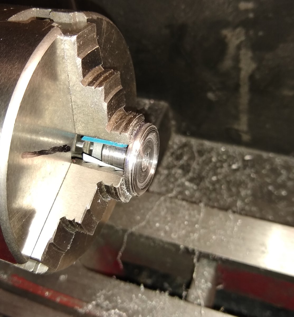
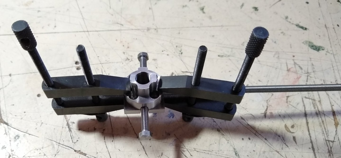
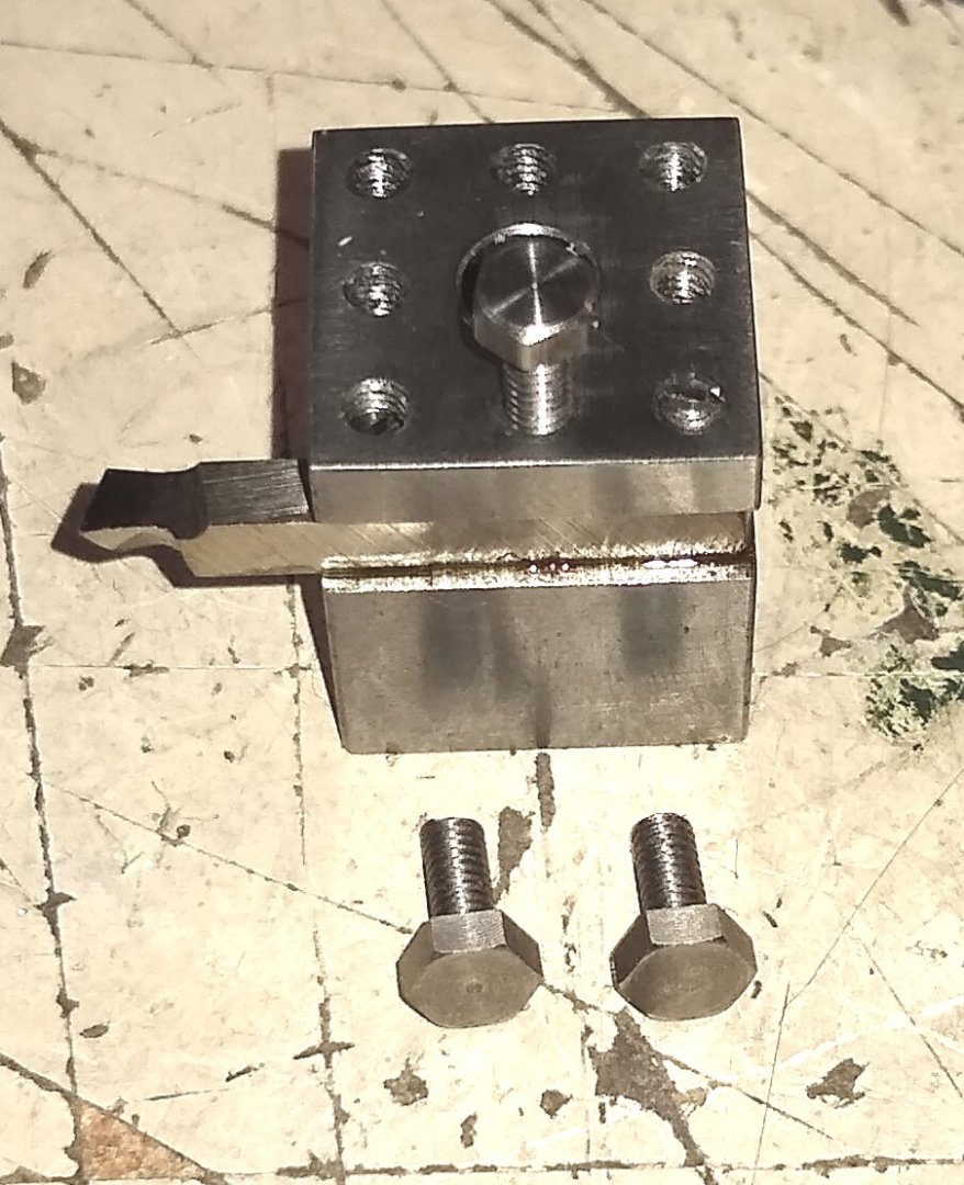
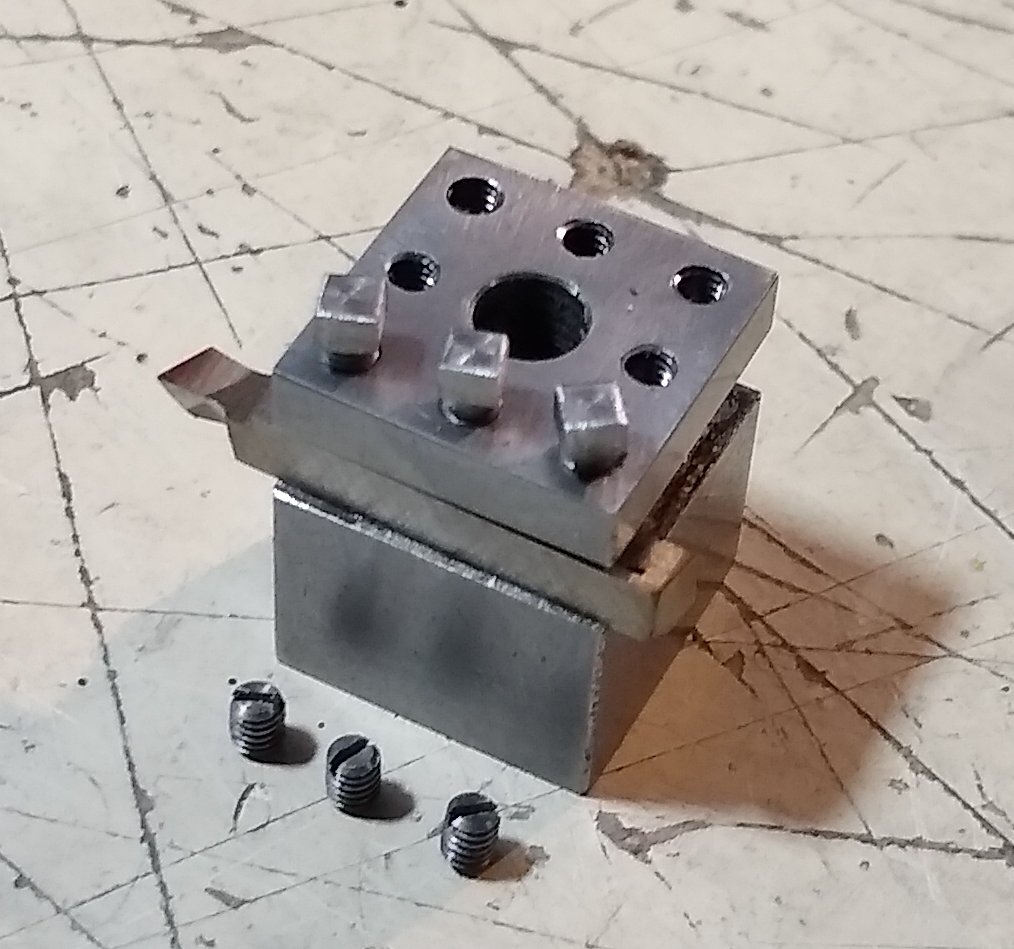
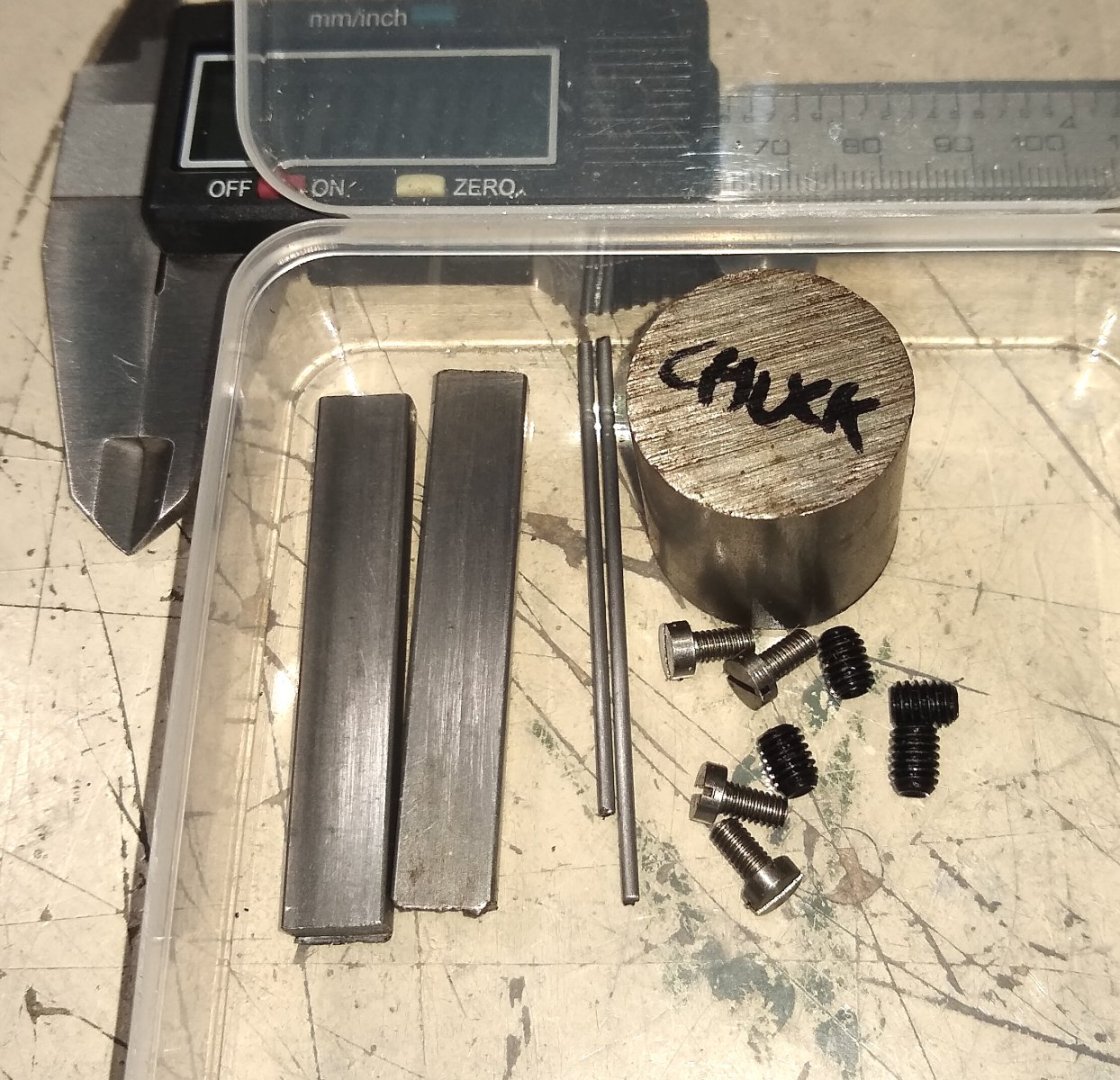
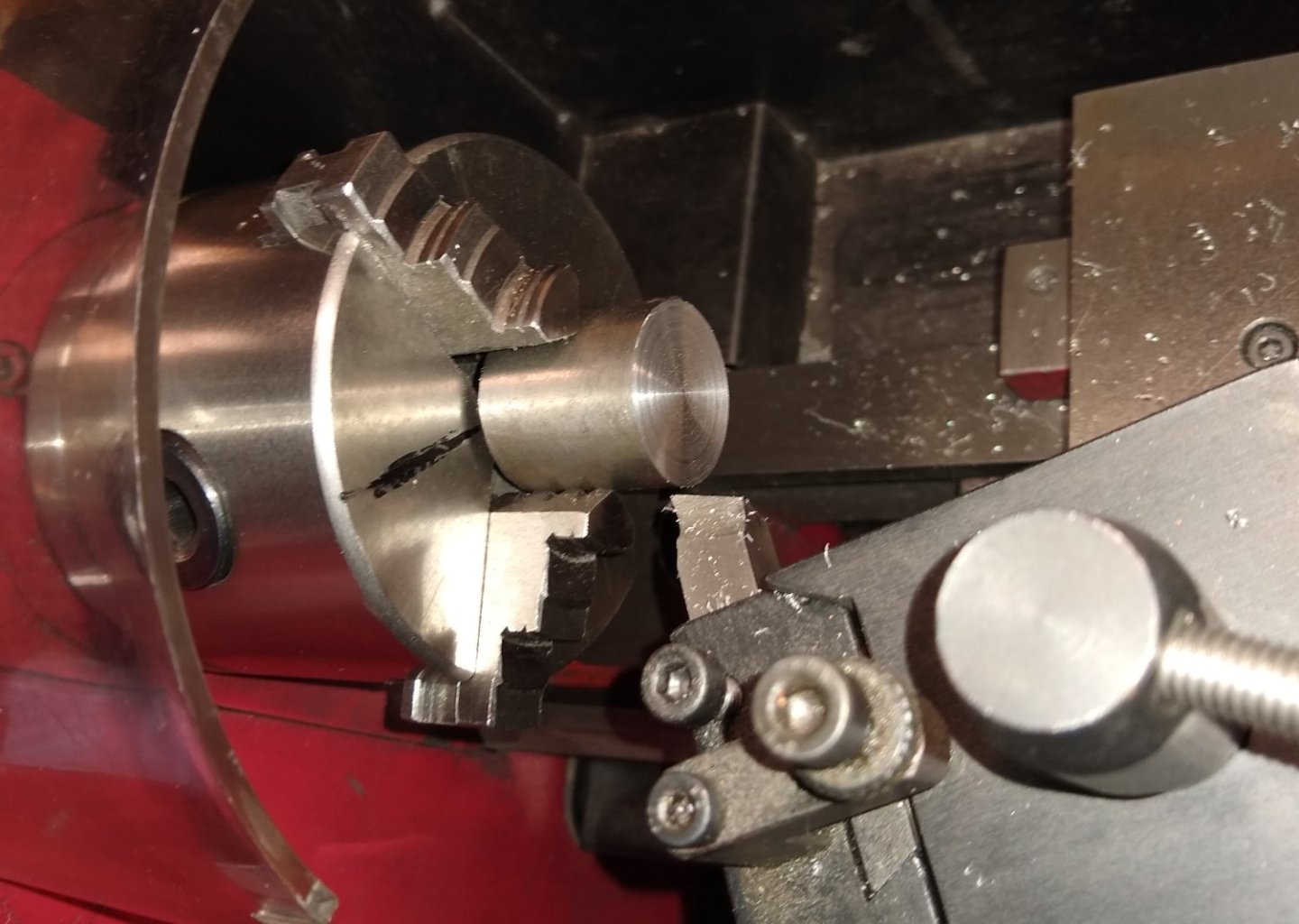
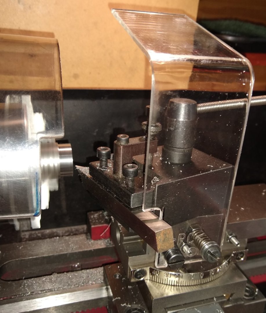
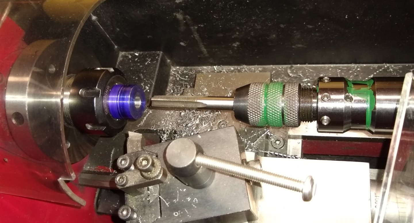
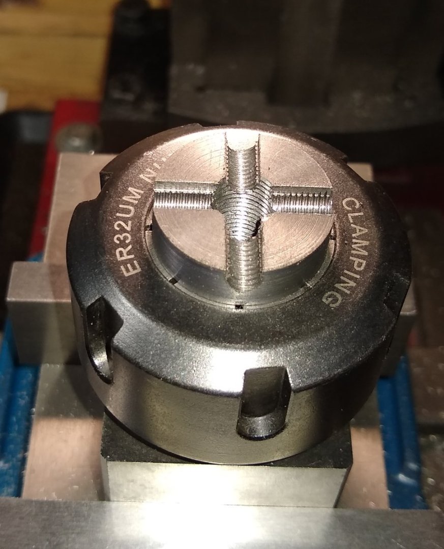
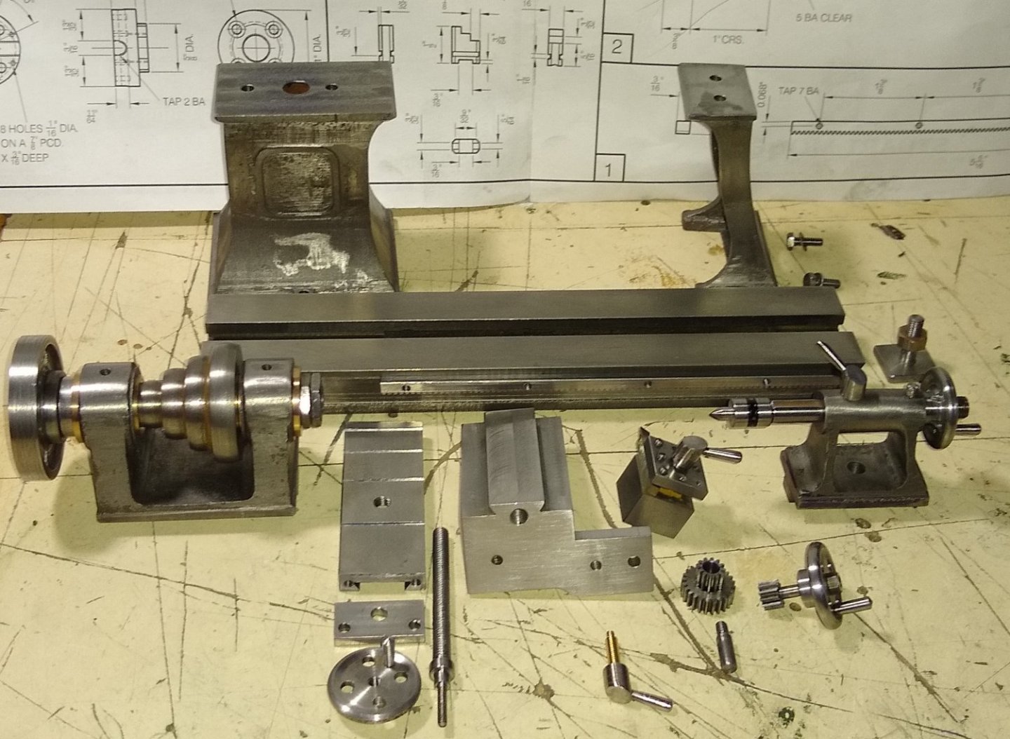
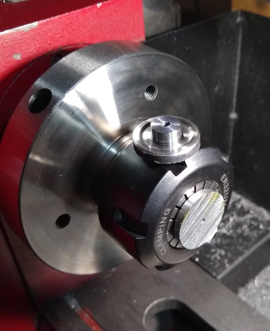
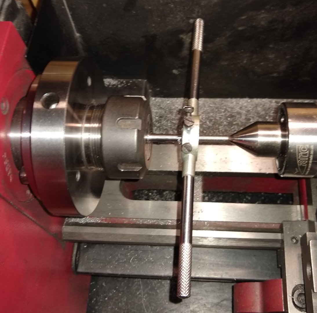
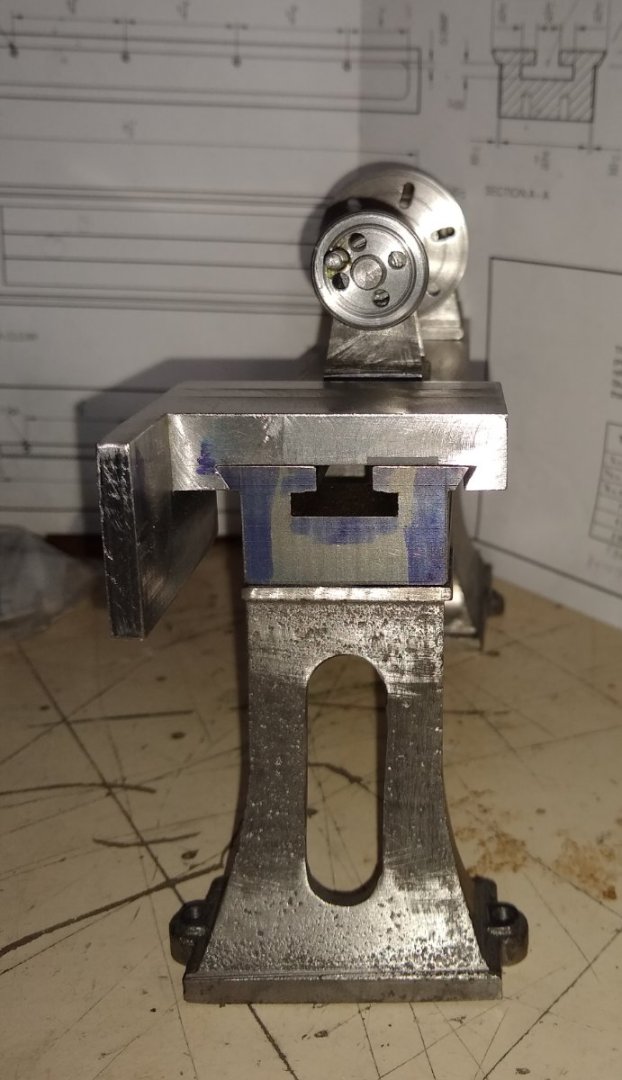
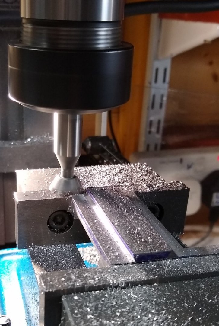
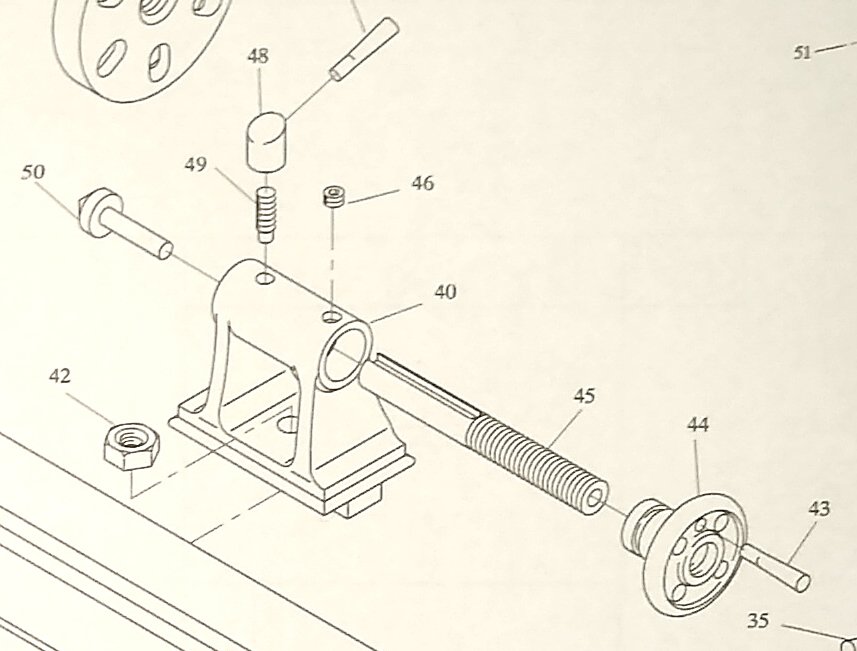
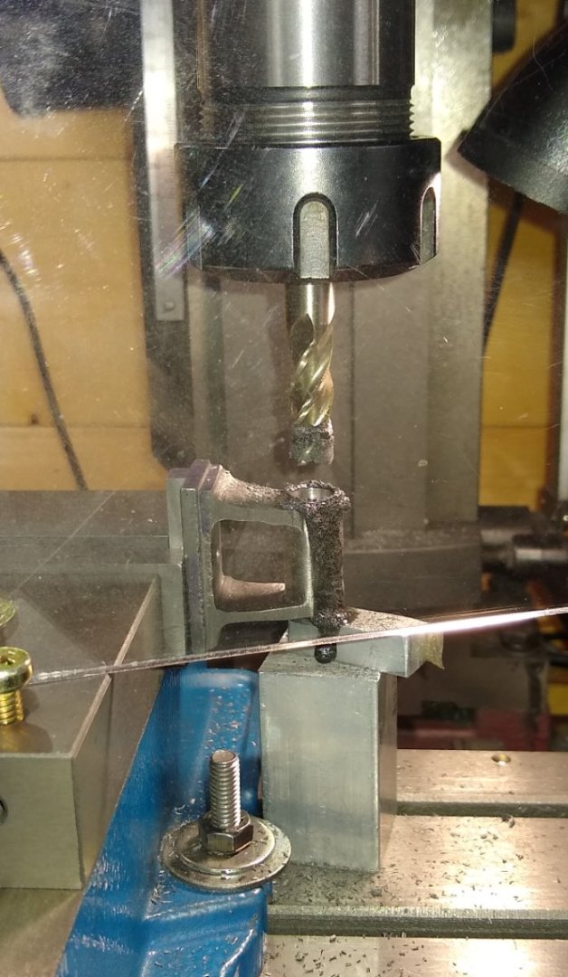
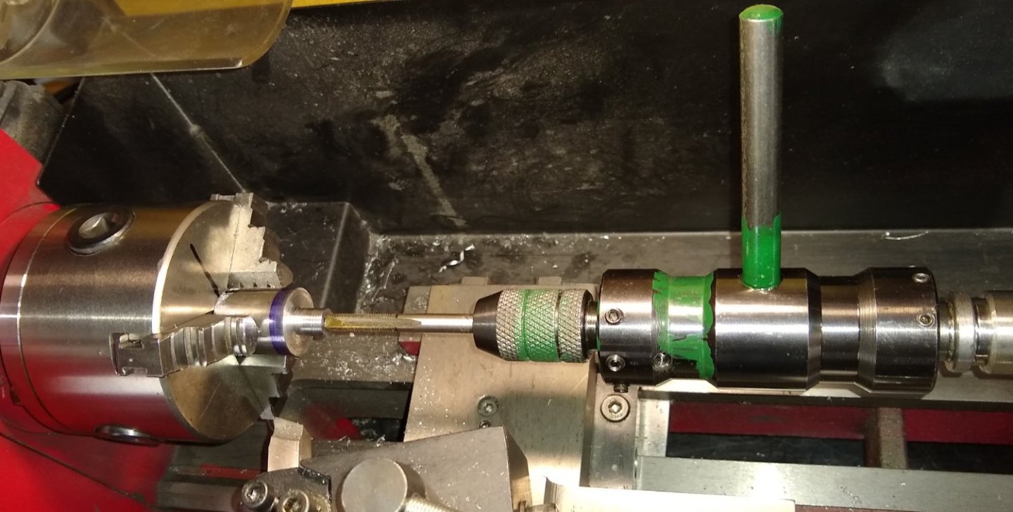
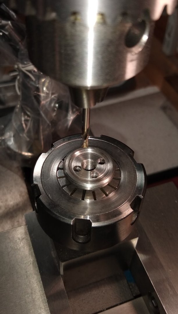
Hi all, This week I was finishing off the tool post, and making a start on the final part, the 4 Jaw Chuck. Below, the Toolpost (Pt 37) and it's parts. I had completed the toolpost last week. It looked fine apart from the slotted head, 7BA grub screws holding the tool - these screws disappear down into the body of the toolpost, which looks kinda strange. So I decided to replace them with hex headed screws, but with the head machined square. Below, the hex screws held in an Anderson square collet block, and the mill taking shavings of the hex head till I got close to the thread but not too close. Without changing anything else, I then rotated the Anderson block in the vice to machine off the remaining 3 hex sides, to end up with a square head. Below, that looks much better ;-). I should really fit square headed screws to the remaining 5 tapped holes.... maybe once I've got all the other parts finished ... maybe. Now on to the 4 Jaw Chuck (Pt 51 etc). I studied this part for quite a while, thinking about machining sequences and workholding. And I got a lot of clues from Joe Pie's excellent video on his PM Research chuck.... https://www.youtube.com/watch?v=KtlXg-iU2XI&list=PL4wikbEbcE3LsyQ_ANNFxaCRs7qIQCvUc&index=4 Unfortunately I don't have a collet large enough to hold the 1" dia of the chuck body, but there is a 5/8" dia on the other side and I do have a 16mm collet which the 5/8" fits nicely in to. So that 5/8" dia was deliberatley made longer than shown on the drawing to give sufficient grip length in the 16mm collet. As a final operation I would machine that 5/8" to it's proper length. Below, the parts supplied by Stuart for the chuck. I replaced the two lengths of 3/16" x 3/8" MS with a length of 3/16" x 1/2" MS... a useful tip from Joe's video. To get a decent 5/8" dia length, I first used the 3 jaw chuck. Thereafter, only collets to maintain concentricity. Machining the 5/8" dia, and showing off the new Chip Guard that I fitted to the Compound Slide - it has proved quite effective, blocking about 80% of the hot chips headed my way. It pivots out of position when access to the toolpost etc is required - however it clashed with the 10mm square HHS tool, so I cut a piece out of the guard and solved that problem. Below, the chuck body now being held in the 16m collet. And then tapping the 3/8" x 26 TPI thread through the chuck body which allows the chuck to fasten on to the Headstock Spindle. The Stuart drawing recommends an 8.4mm tapping drill but I found that too much hard work on the tap, so I opened the hole out to 8.5mm. Note: Joe also correctly mentions that one should not rely on a thread for concentrically mounting one item (a chuck, say) on to another (a spindle, say).... so that is probably on the to-do list 😉 Transferring the 16mm collet back to the square Anderson block on the mill, and preparing the 4 off 2BA tapped holes that will be used to move the chuck jaws in and out. Again, rotaing the Andersen block 90 for each hole was easy - I used a Parallel as an end stop to butt the end of the Anderson block against for positional repeatability. Tapping the four holes. The Starrett T Wrench earns it's keep. It was then back to the lathe to skim off the face with the 4 off 2BA holes, and then back to the mill with the Anderson block now in the upright position. I used a long, straight length of 2BA studding aligned by eye with the edge of the mill bed to achieve squareness. A 3/16" cutter removing the top half of the 2BA threaded holes. And the last pic, showing the chuck body cleaned up and ready for whatever comes next 😉 I'll have a sit down and think about the next sequence of operations...I already have a plan mapped out, but as I work through the operations list I continually reassess the best way forward as further things come to light. If this was a Production item (ie large batch sizes) I would have a set sequence of operations, but as this is a one-off and this is my first time making it then slowly, slowly. See you all in a week or so, Richard


-
Camel by RGL - FINISHED - Machinen Krieger - 1/20
Rik Thistle replied to RGL's topic in Non-ship/categorised builds
Rob, After seeing yours and Greg's work I realise there is another unexplored world out there for me! I have casually watched quite a few YT videos over the years of people weathering models and was very impressed. However it wasn't that relevant to my pastimes, but now that I look closer I'm getting more interested. I'll have a further dig around the internet and see what else I can learn on the subject, thanks. Richard. -
Camel by RGL - FINISHED - Machinen Krieger - 1/20
Rik Thistle replied to RGL's topic in Non-ship/categorised builds
Greg, That looks amazing. I've never done 'weathering', or tried to turn plastic in to metal using paints etc. If I hadn't have known, I'd swear the three pictures above are of a metal device! It's got my interest twitching 🙂 I know there is a wealth of weathering info throughout this website, but I'd like to start at the beginning as a beginner.... so, is there a beginner's book you'd recommend or a 'weathering' beginners website I could visit to commence the learning process? Thanks, Richard -
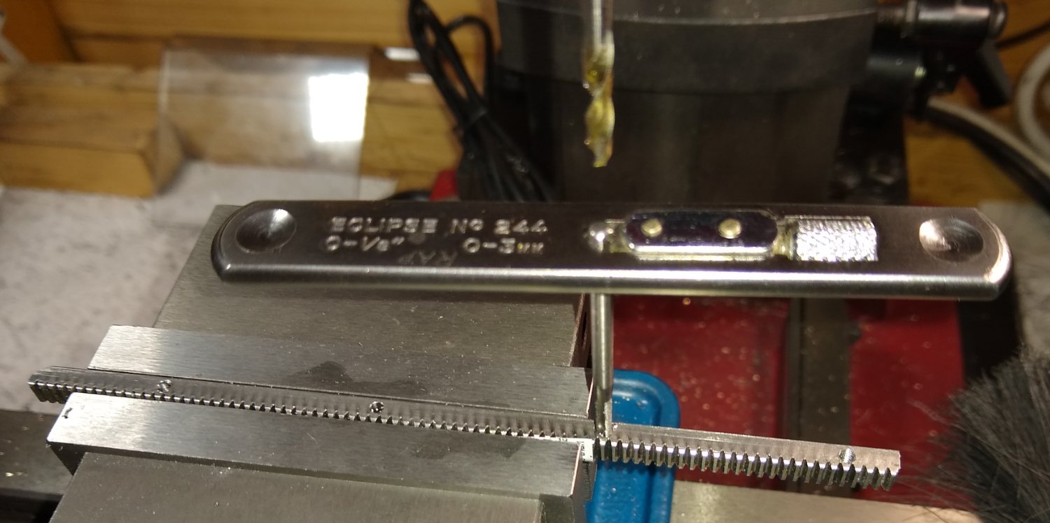
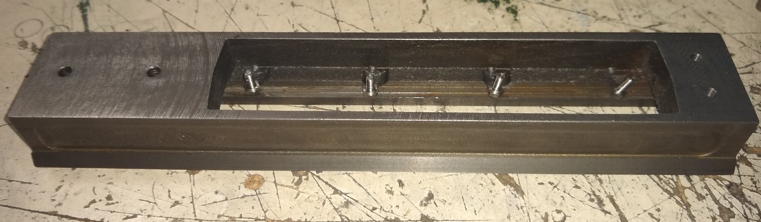
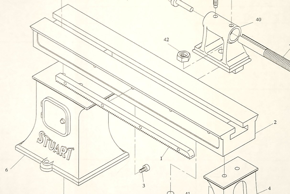
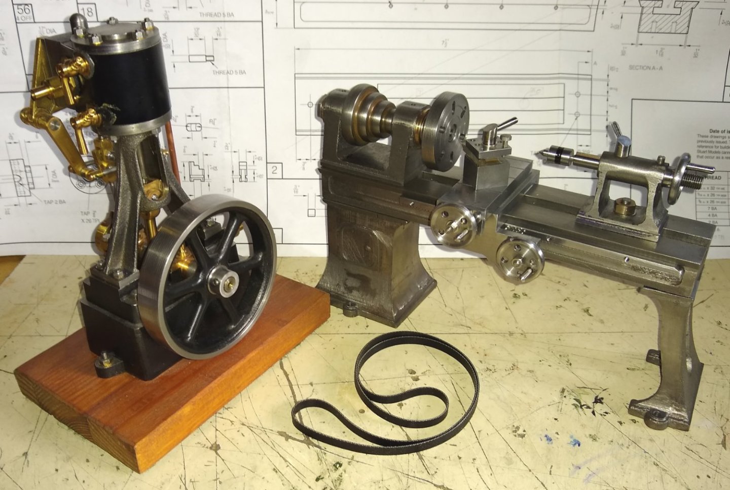
Hi all, This update covers the installation and cleaning-up of most of the lathe's final parts, apart from the soon-to-be-made 4 Jaw Chuck. Below, as usual, a view of all the parts. So focusing first on fitting the Rack (Pt 1) to the lathe bed. The rack allows the saddle to move along the bed using a gear system that interfaces with the rack. Setting the rack up square, prior to drilling and tapping it's 4x 7BA threaded holes for attaching the rack to the bed. Rack teeth protected in the clamping vice using thin Aluminium foil (from a drinks can). The rack is attached using 4x 7BA x 1/4" long hexagonal head screws, seen below sitting next to the tapped holes on an underside view of the bed. The cast bed has reliefs to accommodate the heads of the 7BA hex head screws...however the reliefs do not line up with the tapped holes in the horizontal plane. Even if the reliefs did line up they are still not deep enough...hmm? I double-checked the drawings and my measurements and can't see where I went wrong. Anyway, a solution is always at hand. I decided to mill out larger reliefs for the screw hex heads. That worked fine, but it meant there were now sharp cornered pockets for the Tailstock Clamp (Pt 41) to find as it slid back and forth in the T-slot. I'll try radius'ing the clamps' corners to see if that helps. The saddle has two profiled edges machined on it's front side that have been held back till now since it was useful to have long square edges on the saddle for clamping during other earlier operations on it.. So off to the mill to do the profiling. First profile below. And the second, stepped profile. The Stuart drawing calls up a 1/16" thick mild steel gib (Pt 19) for the saddle. I ordered a 1mm thick piece of brass from eBay instead. An underside view of the bed and saddle's brass gib and the adjusting grub screws. I felt the screws were too short so replaced them with longer screws, to which I also added mildly pointed ends to. I also hand drilled location dimples on the gib to retain the gib in the dovetail...it would fall out otherwise. Below, the brass gib and longer screws assembled in position. Now a look at all the parts made so far. I've still to add oil cups to the headstock, I'll replace the Toolpost tool clamping screws with square headed screws rather than the supplied slot head grub screws, for more realism. I bought a piece of 3mm x 3mm HSS tool stock and then made up a tiny cutting tool for the toolpost. I've mimicked a revolving centre on the tailstock but I wonder if it looks a bit too modern... I'll research if they had those in the late 1800s...surely they must have had something, even if only using plain bearings? Below, the parts assembled together. Everything runs fine...some parts are still a little tight eg the saddle gears, but I have not yet added lubrication. I'll do that after painting, which I think will be Black - but not 100% settled on that yet. My eventual grand plan is to run the lathe using my Stuart 10V engine. I've got the Stuart drive belt but need to figure out a way to add a drive pulley to the 10V crankshaft for the belt to run on. Adding the Reversing gear to the 10V used up the last remaining protruding section of the crankshaft....thinking...I may be able to grab back a few millimetres from the shaft by reducing the lengths of the flywheel bosses, and shaving a bit off the bearing boss next to the flywheel. Yup, still thinking... Next post should concentrate on the final part, the lathe's four jaw chuck. It looks like a mini-project in it's own right 🙂 Well, that's it for this week, Take care, Richard


-
Speakers' Corner etc - I seem to remember there were also impromptu 'art galleries' in that locality where artisits would hang their for-sale paintings on the park railings, and pavement artists used chalk to amazing effect. It was really quite pleasant, especially on a busy summer's day. I stayed initially in Highbury, and then Wembley. But i also haven't been back for many years, apart from a couple of day trips. All towns/cities change as time goes by, some more than others. London seems to now have more than it's fair share of high rise buildings in the centre, but that will be because land is so expensive and the technology to build them high is now refined and cheap. Thankfully the heart of Edinburgh is reasonably untouchable, in spite of the money-peoples' best efforts ....new tram system notwithstanding! As you say, every is in flux 🙂 Richard
-
Welfalck, Your website contains a lot of very interesting information. I remember looking at it a year or so ago, particularly your photographs of London eg Speakers' Corner (1973) and wondered if we may have stood there at the same time listening to who ever was on the soapbox that day. I was a 'Londoner' from '73-'83. Anyway, I read through your details on the ball handle manufacture. Very fine workmanship, in both senses. Once I have gained a bit more confidence/expertise from my machining adventures I may attempt similar...but you do work at a level of detail much smaller than I am used to. Your 24/02/18 video addendum is good. It gives a feel for the scale and precision of your projects. Thanks, Richard
-
Wefalck, Thanks for the link. I'll examine the info on your website tomorrow on my large destop screen (...on a laptop at the moment). turning sleeves on the handles of crank-wheels - that's what's on my Sieg kit. Fortunately the Sieg plastic wheels, have large knurling on the perimeter which gives some degree of fine control, but does get tiring fairly quickly. Richard
-
Maybe cast iron handwheels, at 25mm diameter appx, are probably not worth the casting complexity. I'm not sure if the PM Reseach ones are cast, but they would be made from Aluminium which may be easier and cheaper to cast. As a side note, machining cast iron is a dirty business...my benches are stained with cast iron dust in spite of very regular cleaning by me. That is one advantage of the Aluminium PM Research models that I won't underestimate in future 🙂 Yes, ball handles are a delight to use....much easier to control wheel movement than a single shaft sticking out. I noticed, IIRC, Joe Pie did ball handles on his PMR lathe. My Sieg lathe and mill have the single shaft handle design, which is hard on the hands, lacks feel and, one day, will be replaced by more ergonomic wheels. Richard
-
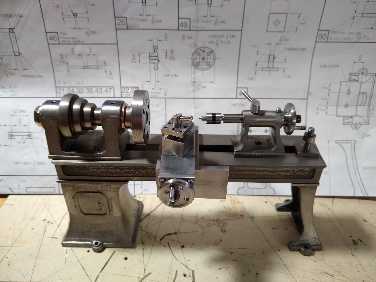
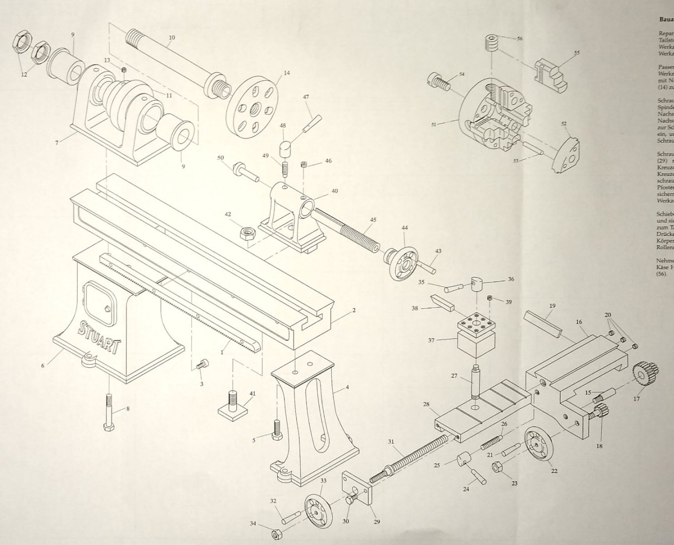
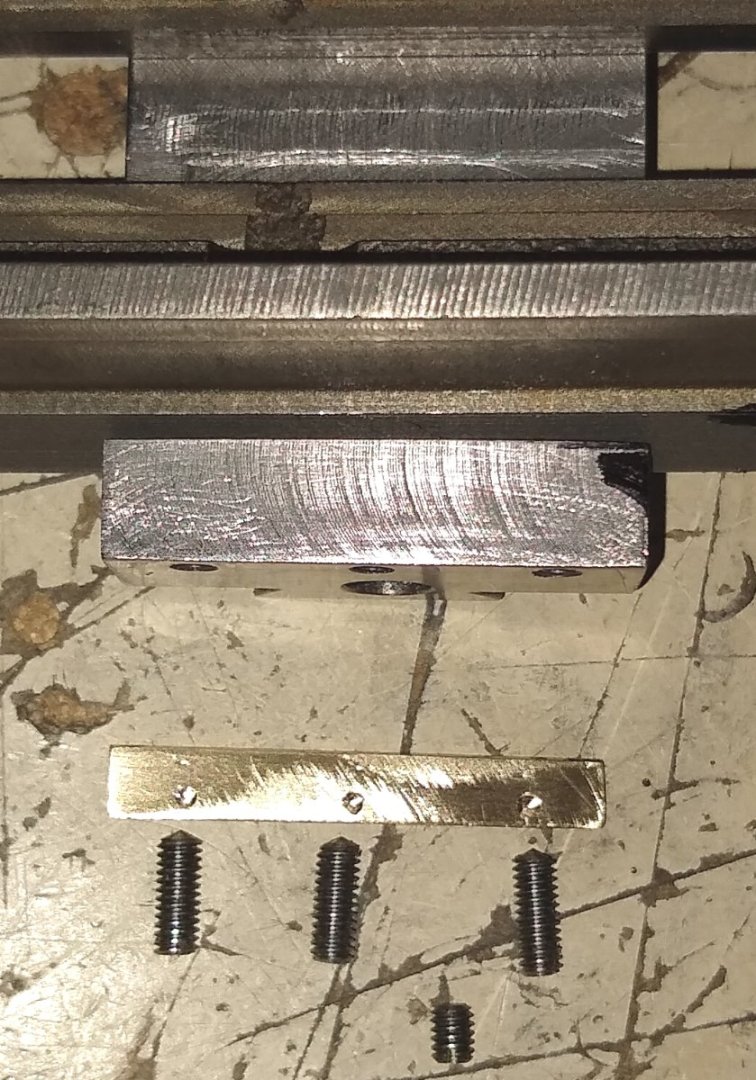
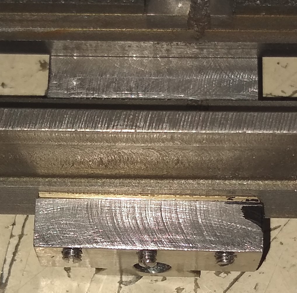
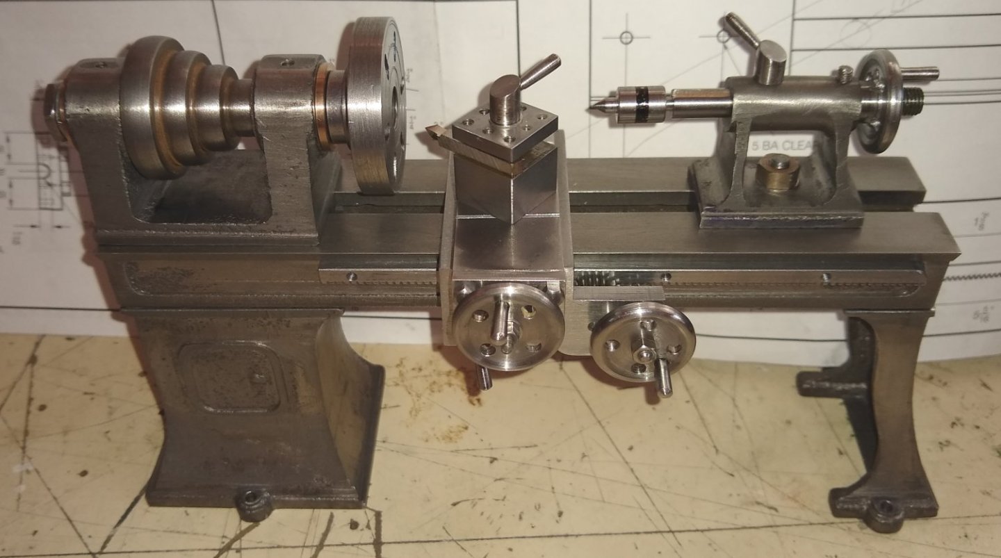
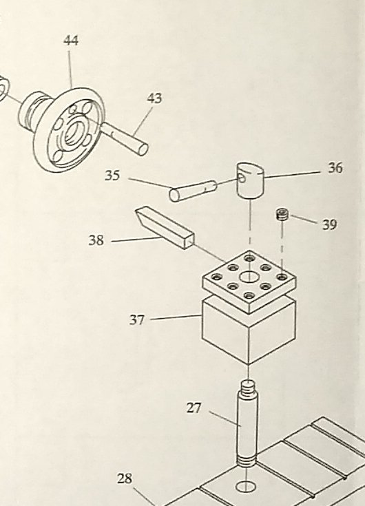
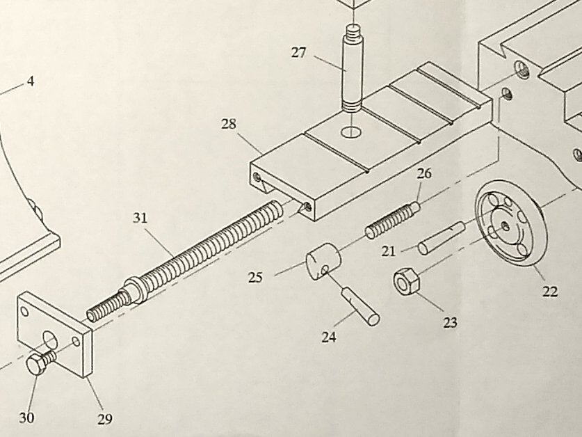
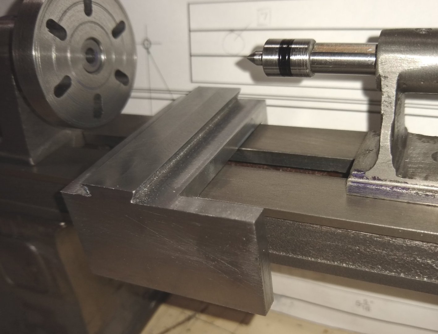
Hi all, A short update on progress over the last week or so on the Stuart Engineering Lathe model. Below, a reminder of the lathe parts. Firstly, let's look at the remaining two Handwheels (Pts 33 & 22, for the Cross Slide and Saddle) that were still to be made ...they are the same as the Tailstock's wheel, Pt 44. I probably should have made all three at the same time but was keen to get the Tailstock finished a few weeks ago. The final two Handwheels followed exactly the same procedure as the first one ie turn to shape on the lathe... ...and drill the holes on the mill using a square Anderson block for the four equi-spaced 1/8" dia holes. Shown is the central hole being drilled before tapping. The washer was used to space the wheel away from the collet for when the drill broke through. The Toolpost, Pt 37, was made from a piece of 5/8" square mild steel. Below, I'm marking up the positions of the 8 holes for clamping the lathe cutting tool, and also marking the undercut below those holes that the cutting tool fits in to. I found the 'circular rod centre marking' square quite useful for finding the centre of square bar. Below, all 8x clamping holes drilled, and the hole for the Toolpost Column (Pt 27) about to be drilled using a stub drill. And milling out the slot for the lathe's cutting tool to sit in. All pretty straightforward stuff. Once that Op was finished the 5/8" square length was sawn almost to length and then cleaned up on the mill. There are three identical handles used on the lathe (eg Pts 35 and 36). Here is the handle body having it's sloped top milled on. And drilling the hole to accept the handle lever. Yup, I decided to make all three items (...the handles) at once this time. Although it slows down the flow of the particular area I am working on, it means I don't have to set up the tooling more than once and also don't have to re-remember what I did the first time round 🙂 Yup, one of the handle bodies is a bit shorter than the other two...I ran out of material....cough. And the lathe assembly with the new Toolpost (+ handle + grub screws for clamping the tool) and the cross slide Wheel fitted. Now, returning to the Saddle (Pt 16). There is still a bit of machining to do here, mostly involving drilling and tapping (some) holes. Below, drilling and tapping the 3x holes for clamping the saddle Gib (Pt 19) in place. The 1mm thick brass for the gib arrived today so it should get machined to size in the next few days. Note: the central, long through-hole that was drilled from the other side last week, to give clearance for the leadscrew can be seen to have wandered slightly off-centre...but the leadscrew still cleared it, so all OK. Below, fairly standard pic of the gib screw holes being tapped. They did seem to emerge in the middle of the internal dovetail slope, so hopefully the screws won't impose any tilting action on the gib when the time comes. Sigh... 🙂 ... another tapping picture...this time for the saddle handle (Pt 25) and the Saddle Gear (Pt 17). Also drilled was the hole for the Rack Gear (Pt 18). I was now getting to the stage where it was time to try a dry fit of the Rack (Pt 1) to the Bed (Pt2), and then run the Saddle over the rack with it's gears fitted to see if there were any fitting issues before screwing the Rack in place. Below, an image of the dry assembly. It initially did feel that all ran smoothly up and down the length of the lathe bed.... there isn't a lot of clearance between the parts but just enough to prevent interference .... almost. A close-up of where the Rack tucks up in to the undercut on the lathe bed shows a slight, raggedy burr running along the undercut. This needed to be removed to make doubly sure the rack sat down completely square.. I also thought it prudent to slightly chamfer the top corner of the rack where it tucks in. Cleaning up the burr on the bed. The middle of the bed was slightly higher (to the cutter) so a little more metal was taken off, but nothing to worry about. It may be the 'spacer' (still left in position from a few weeks ago, just in case) was pushing the bed sides out, or perhaps more likely the casting had expanded in the middle due to earlier metal removal. Finally, a dry assembly pic of the rack and saddle gearing before it is drilled and fastened in to place. I still have to clean up a lot of faces, radii etc but that will be left till I get close to the painting stage. That's it for this week. See you soon, Richard.


-
BE, Although I haven't commented on this built I've keenly followed it. Apart from the wonderful craftsmanship, I think you have got the art of displaying models nailed. Too often I see lovely models swamped inside an overbearing display unit....not the case here! The eye is drawn immediately to the model. And the book is a wonderful idea, which I've seen you do on your other models. I imagine there is no little amount of work required in laying out the book prior to it getting published. I can visualise you sitting in that comfortable armchair, next to the displays, flicking through the pages of the book with a suitable beverage in hand ...and a big smile 🙂 Kind regards, Richard
- 858 replies
-
- 5
-
-

-
- Sphinx
- Vanguard Models
- (and 1 more)
-
Wefalck, Yes, that long hole was a bit of a 'fingers crossed' moment .... I started it off with a stub drill, pecking and carefully going as deep as the drill could, then followed up with a standard drill with just enough length sticking out of the chuck. The hole emerged at the other end slightly off-centre but as good as I could have hoped for. No gib on the cross slide, but there is one between the saddle and the lathe bed dovetail. And well, yes, the thread cut directly into the saddle...so lots of compromises in the kit design. I haven't yet checked Joe Pie's build of the PM Research lathe to see if that design incorporates a cross slide gib. However, this German gentleman has built the Stuart lathe with a brass gib in the cross slide and added a Compound Slide...... https://www.ekt-modelle.de/Stuart-Drehbank.htm This is by far the best interpretation I've seen of the Stuart lathe. He also has a number of other models on the site that I will, no doubt, spend a fair bit of time today looking at and admiring. Richard
-
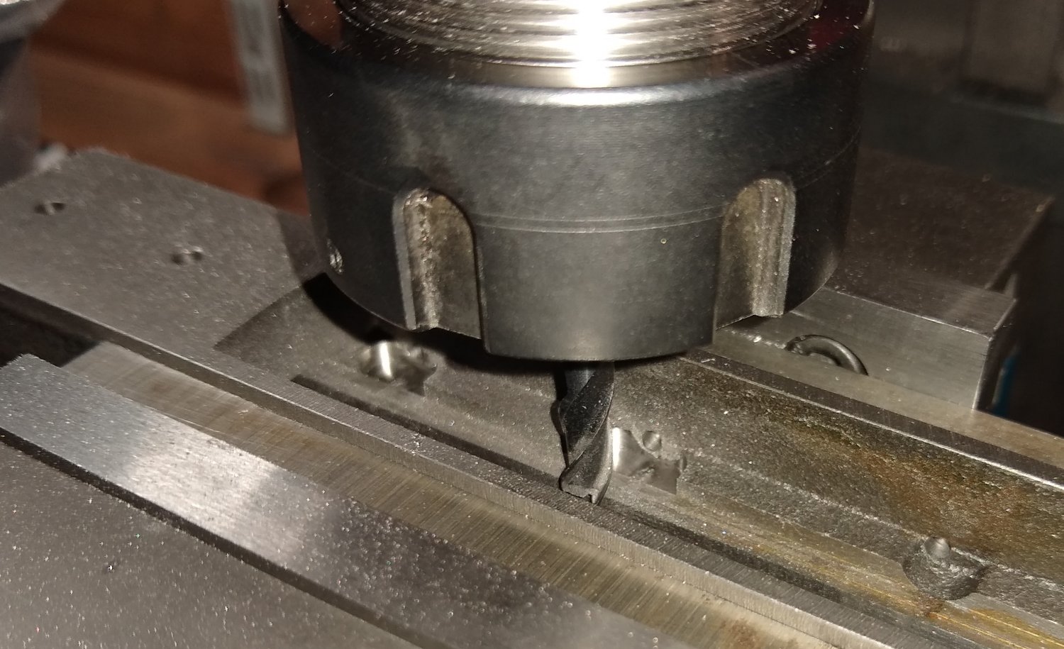
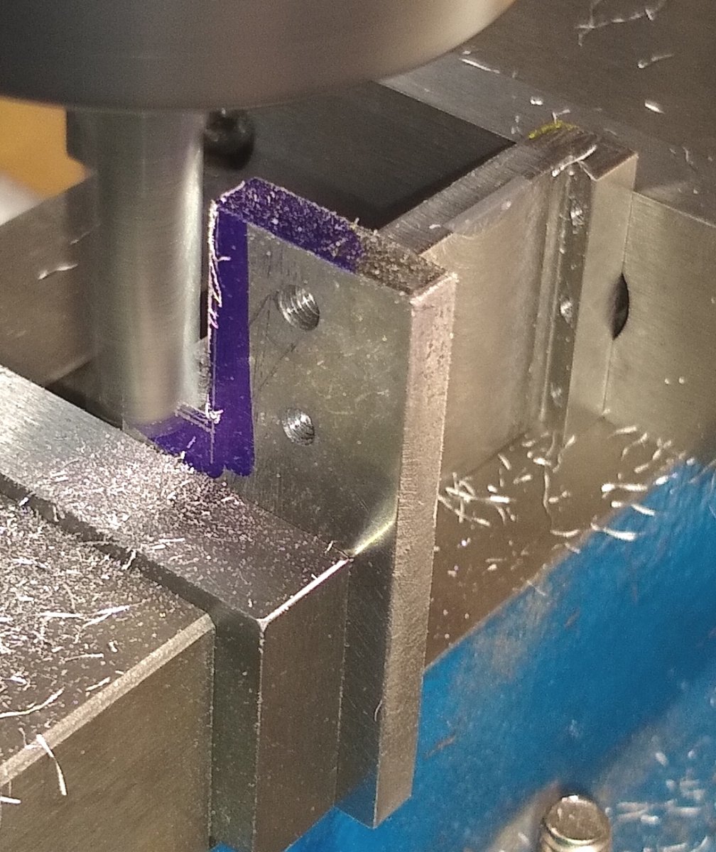
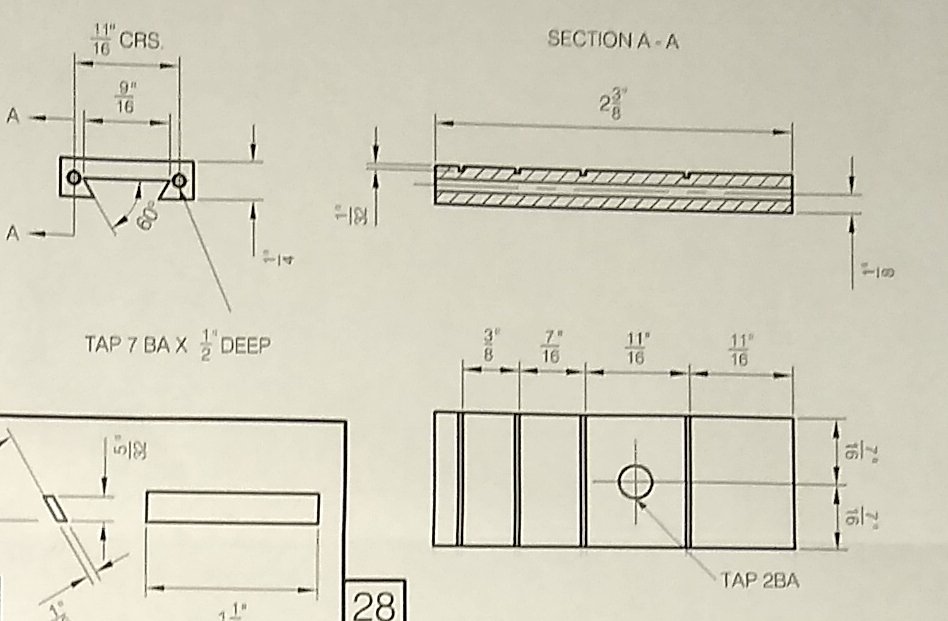
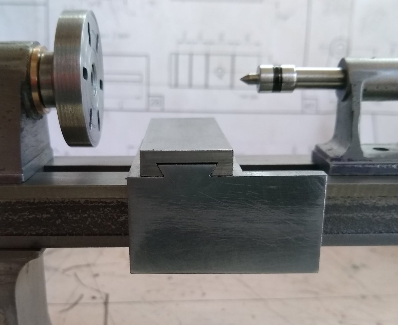
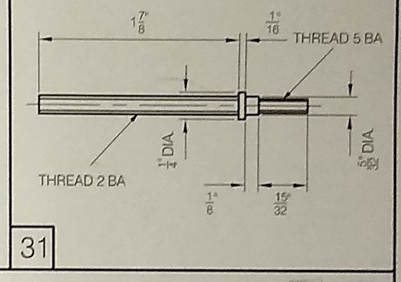
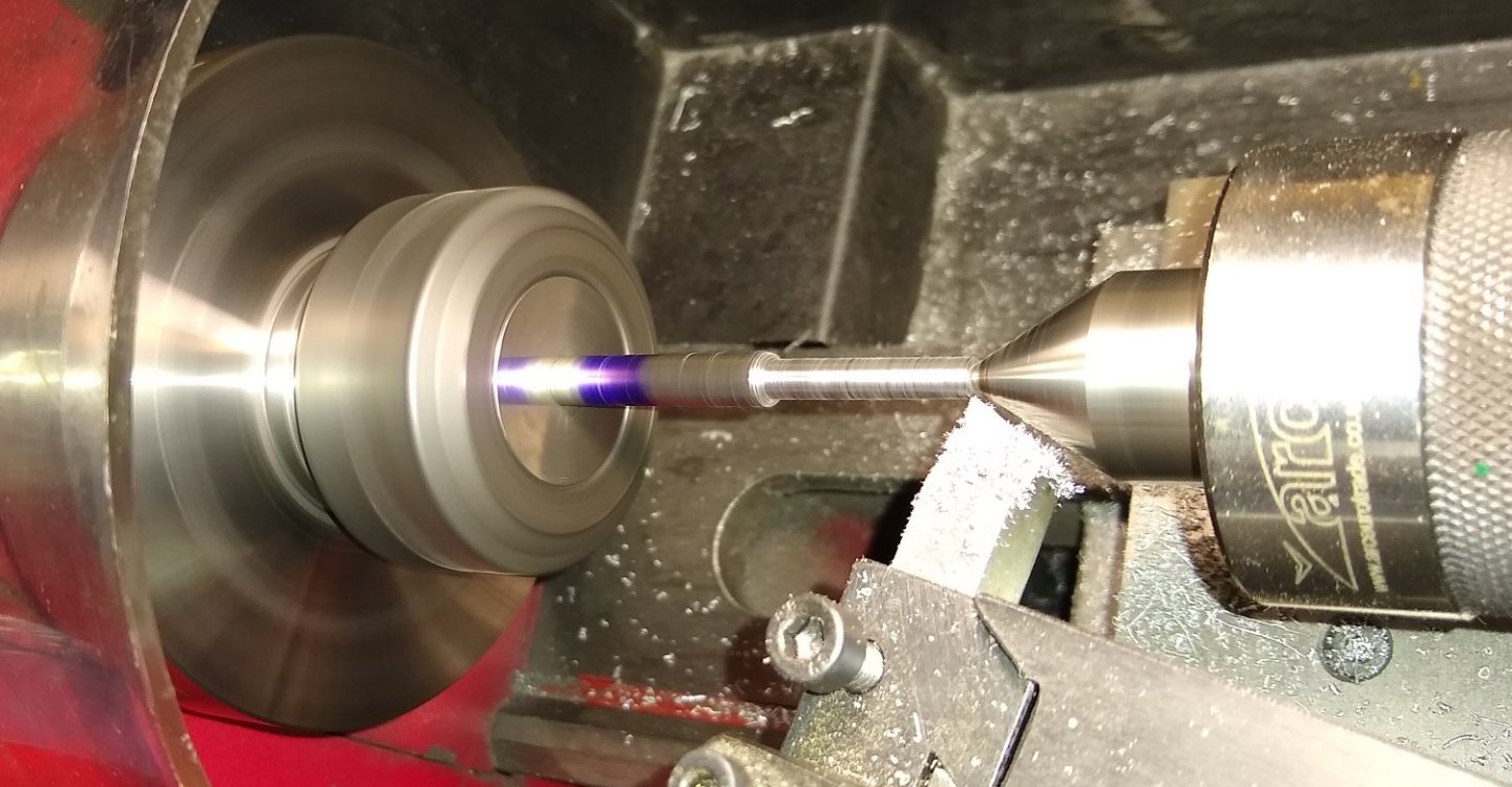
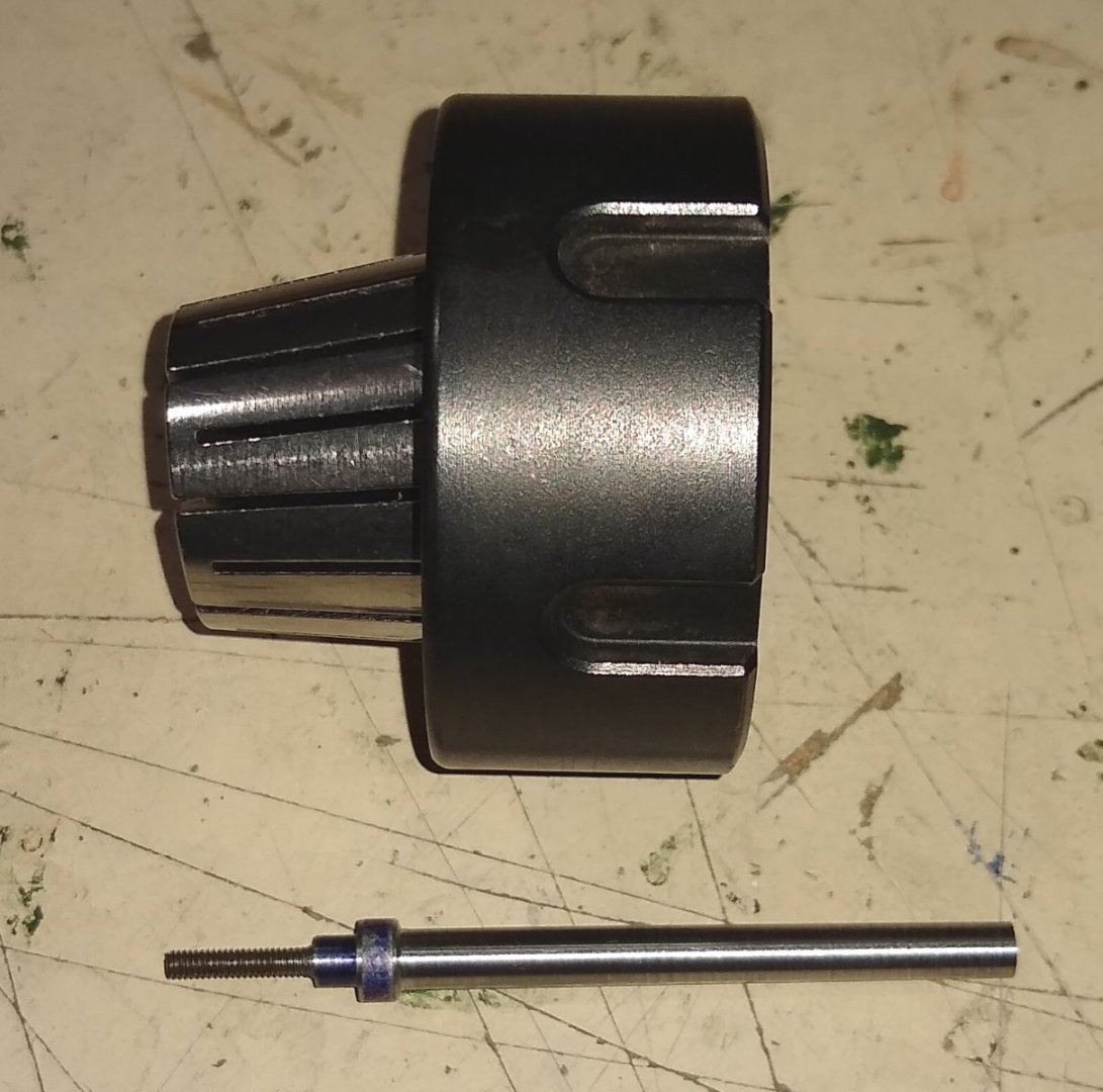
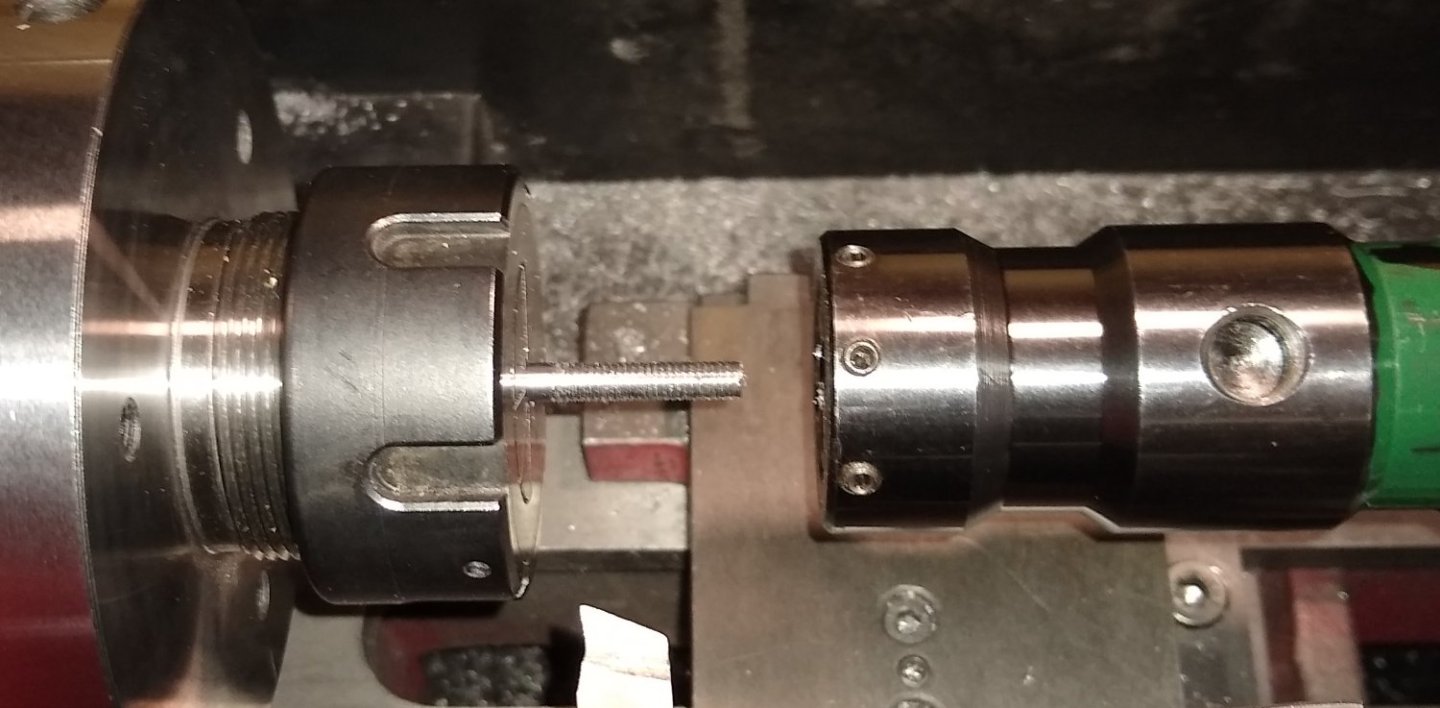
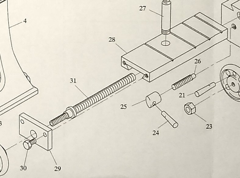
Hi all, This post will focus on the lathe's Cross Slide (Pt 28), which mates with the Saddle's top dovetail. Below, a reminder of the grand plan. And here is the Cross Slide. Pts 29, 31, 28, 27, and the Saddle (Pt 16) should all make an appearance today 😉 But first, the main character, the Cross Slide. It's female dovetail mate's with the male dovetail slot on the top of the saddle. A sliding fit would be a good result, but in real life there would be an adjustable strip of metal (called a gib) to fill in the deliberate gap between the two dovetails - the gib is adjustable to compensate for fit and wear. The detail drawing of the Cross Slide. The two 7BA tapped holes seemed a tad too close to the corners of the dovetail slot for comfort, but I went with it anyway. The 2BA hole in the middle will accommodate the tool post column. Cleaning up the ends of the Cross Slide before milling out the bulk of the dovetail slot and then using the 60 deg dovetail cutter. And jumping ahead to the Cross Slide fitted nicely on to the saddle (...yup, I forgot to take pics of the dovetail being machined, but it looks just like the saddle machining did). The relative movement of the Cross Slide and saddle is controlled by a leadscrew. So the saddle needs a drilled hole to accommodate the leadscrew, with one end of the hole tapped 2BA (see centre view below). About to drill right through the length of the saddle with a 2BA tapping drill. 2BA tapping of the front end of the saddle's drilled hole. I'm using the chuck as a visual guide to help keep the tap wrench vertical. And now at the other end of the saddle, opening up the drilled hole to give 2BA clearance up to about 1/2" from the front face. This is the Leadscrew (Pt 31) that allows the Cross Slide to move relative to the saddle. As with a lot of parts I had to sit and think as to how to make this and in what sequence - that's a long, spindly 2BA thread! I decided to make a centre hole in the end of the rod, hold that end in a live centre and the other end in the collett. Then machine the diameter, in two sections, down to the 2BA threading size. The leadscrew, with a 7BA thread on one end (it should have been 5BA...whoops) , locating diameters and bare 2BA portion ready for threading. I tucked the leadscrew in from the back of the collett to give a strong start to the 2BA threading process. This was as much as would stick through the collett - I don't think I'd want any more anyway. And a 2BA die holder located on the tailstock to keep things square. A 2BA nut threaded on to check the thread had been cut to a reasonably snug fit. Now the leadscrew is taken out of the rear of the collett and re-located back on the live centre. And a simple die holder used to finish the threading. I couldn't use the 'green' die holder for this since there was little material to be held square enough in the collett. The Cross slide and associated parts. Pt 29 (the Keep plate) was finished 'off camera'. Almost there 😉 .... adding some fake T-Slots to the Cross Slide. I'm always very wary of slitting saws for some reason, hence two plastic guard sheets on duty. And finally, the Cross Slide fitted to the lathe. The toolpost column was also done off camera. It all fits together well and the Cross Slide (sans wheel) moves smoothly over the saddle. This post describes machining that is probably a bit nitty-gritty, but needs to be done nonetheless. Although it may not seem that exciting I found that I spend about 80% of my time measuring and planning what to do rather than doing.....just like model ship building I guess 😉 Thanks, Richard


-
Roger, EG, Thanks for the comments. I find sketching a useful aid, and having been, in the earlier part of my career, a trained design draughtsman (BS308) it kinda comes naturally to me. Machining on the other hand, I feel I have a ways to go, which is fine since learning is enjoyable. Some of the machinists on YouTube are an order of magnitude away from me but that is their forte. Clickspring, although not a heavy machinist, displays some extraordinary skills and patience .... https://www.youtube.com/c/Clickspring/videos ... not least his work on the Antikythera Mechanism. Richard
-
Wefalck, Yes, if one part was crying out to be a casting it might be the saddle. It certainly would have saved me a lot of hacksawing, good exercise as it was. But, as you say, clamping would not be so easy on a casting. And as there was quite a bit of heavy machining going on, I wonder if a skinny cast iron part may have cracked, particularly with the hard outer skin on Stuart's castings. When I say 'heavy' the deepest cuts I tend to take with my end mills are about 10th (0.25mm). My milling machine isn't particularly sturdy and starts to vibrate if I go much above 0.25mm. But it is what it is, and for the price I paid, very good. Also a larger more powerful machine could get me in to a lot more trouble so I'm more than happy to live with my mill's shortcomings. Richard
-
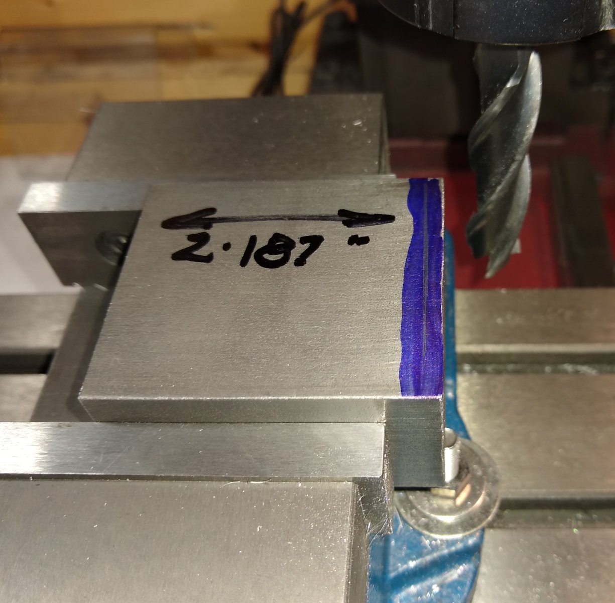
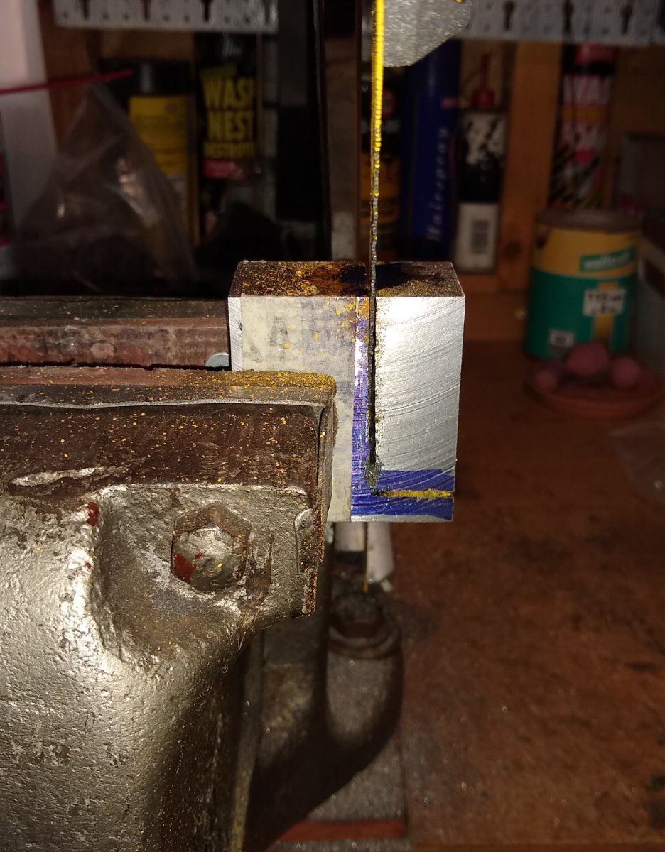
Hi all, This week's update on my Stuart miniature lathe's progress. Above, a reminder of where I am headed. And below, the subject of this post, Item 16 - the Saddle. The saddle is a fairly complex part with dovetail slots at 90 deg to each other and a number of holes etc. I'll concentrate today on rough machining the part to size and the dovetails. Below, I like to do a quick sketch of all parts I make since it gets my mind round what the part looks like, checks dimensions for correctness and/or omission. and helps formulate a plan of which order to machine the features and the appropriate clamping/work holding. With 'one-offs' like this I don't think there is ever a correct 'order' since people use different machines and have different skill sets, but my aim is to avoid finding myself halfway through machining the part and discovering I should have left meat in a certain area for clamping to, say...but unfortunately have already removed that meat. So here is the saddle, as it arrives from Stuart Models....a 2 1/4" x 2" x 1 1/4" lump of mild steel. After blueing the surfaces and scribing the dimension lines, I machined the block to an accurate rectangle. On some of the block's surfaces I used a 16 mm dia end mill, but reverted to a flycutter to speed things up. Flycutters tend to leave a rougher surface finish (...I'm still learning how to best grind the tool point) and tries to throw swarf into the next county...hence the extra Perspex shield (...this was later titied up into a more permanent solution). After machining to a correct sized rectangle, I needed to remove two large portions of the rectangle. I don't have a power hacksaw or bandsaw, so elbow grease was used. Below, the saddle hacked to something closer to it's final shape and then the sawn faces machined smooth and to size. The saddle positioned on the lathe bed with features drawn on it, again to give me a mental picture of what I was striving to achieve. Below, the first step in shaping one of the dovetails - metal removal using the 16mm endmill. And then forming the dovetail using a 60 deg cutter. It was only after inspecting these pictures I realised I had turned the part through 180 deg in the vice, from the roughing end mill cut. The tramming on the mill is not perfect so this introduced cuts which were not parallel. I later orientated the saddle block back to it's original position and touched-up the dovetail slots to make them parallel with the block faces. An atmospheric shot of the dovetail cutter, just for the heck of it 🙂 Below, the first dovetail cut and trial-fitted on the lathe bed. A close up shows three things... a) on the right side, the gap for the gib to fit in. Stuart calls up a 1/16" thick mild steel gib; I feel this is out of proportion so will use a slimmer brass gib. b) a grey, narrow oblong above that side of the dovetail that looks suspiciously like JB Weld....yup, I was distracted by the mill's Z axis DRO malfunctioning so forgot to clamp the mill head down before starting the cut. Moral - don't be distracted. c) the 'walk of shame' step in the T-Slot is still present ...it WILL be removed by the end of the project, honestly. Now on to the dovetail for the Cross Slide to run along. And the same 60 deg cutter is called in to action again. It was a cheapo cutter but is standing up quite well, so far. And the saddle with both dovetails machined sitting on the lathe bed. It's looking OK so far. There are a number of other features yet to be machined in to the saddle but I will leave them for now as these features 'mate' with other, as of yet, unmade parts. Talking of which, item 28 - the Cross Slide. This is next on the to-do list, and has a dovetail slot which fits on the saddle. So this will be the subject of my next post. Well, that's all for today, take care. Richard


-
B.E., Looking good. I hope we will see something being cooked on your finished stove 😉 Which makes me ponder what did they actually cook on these stoves, how many and how quickly could the stove serve the crew, and what fuel did they use? OK, off for a wander around Google.... Richard Edit: Found this ... 'Cooking on wooden sailing ships in the 1700s and 1800s' - https://margaretmuirauthor.blogspot.com/2012/11/cooking-on-wooden-sailing-ships-in.html 'Cooking could be done in the oven but the pork and beef was boiled in large round pots which sat in large round holes on the top - next to the hanging net bags into which each mess-table put its 6 pieces of meat and each bag was labled with the table’s name. To prevent heat descending to the wooden deck, beneath the fire hearth was a layer of sand with bricks, slate or stone slabs.'
- 27 replies
-
- 2
-
-
- galley stove
- Syren Ship Model Company
- (and 1 more)
-
Welfalck, Yes, Stuart cheaped out 🙂 I see what you mean though by the tapered bush/spindle .... not totally impossible to make even for a model but I'll leave that 'mod' for another day. There is a slightly more elaborate model lathe on the market ... https://www.pmmodelengines.com/shop/machine-tools/machine-models/engine-lathe-kit/ ... .... which tends to use Aluminium rather than cast iron. The talented Joe Pie does an excellent build on it ... I had considered doing this one rather than the Stuart, but Stuart is 'local' (ie in the UK) so easier/cheaper/quicker to get replacement parts from since PM Research is USA based. Regards, Richard
-
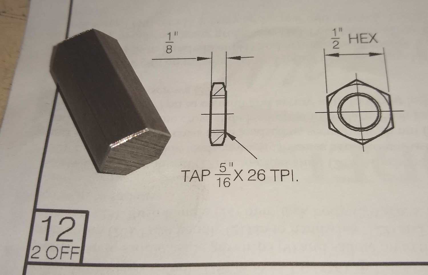
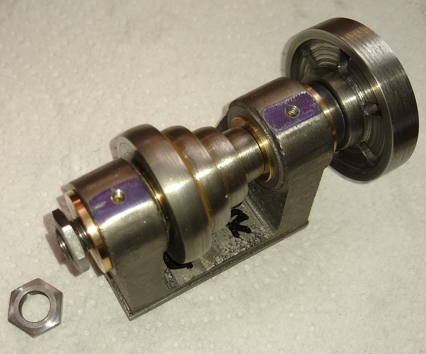
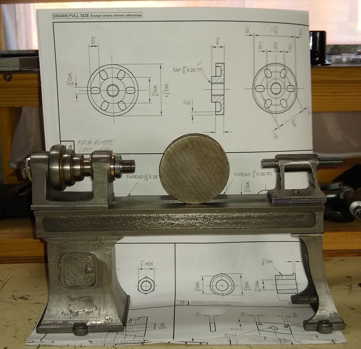
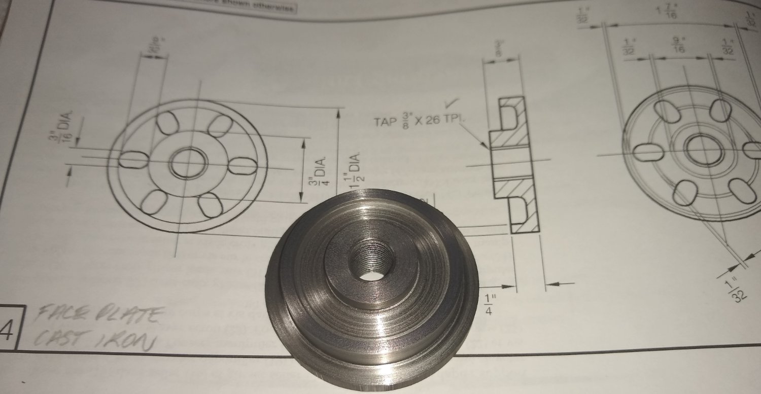
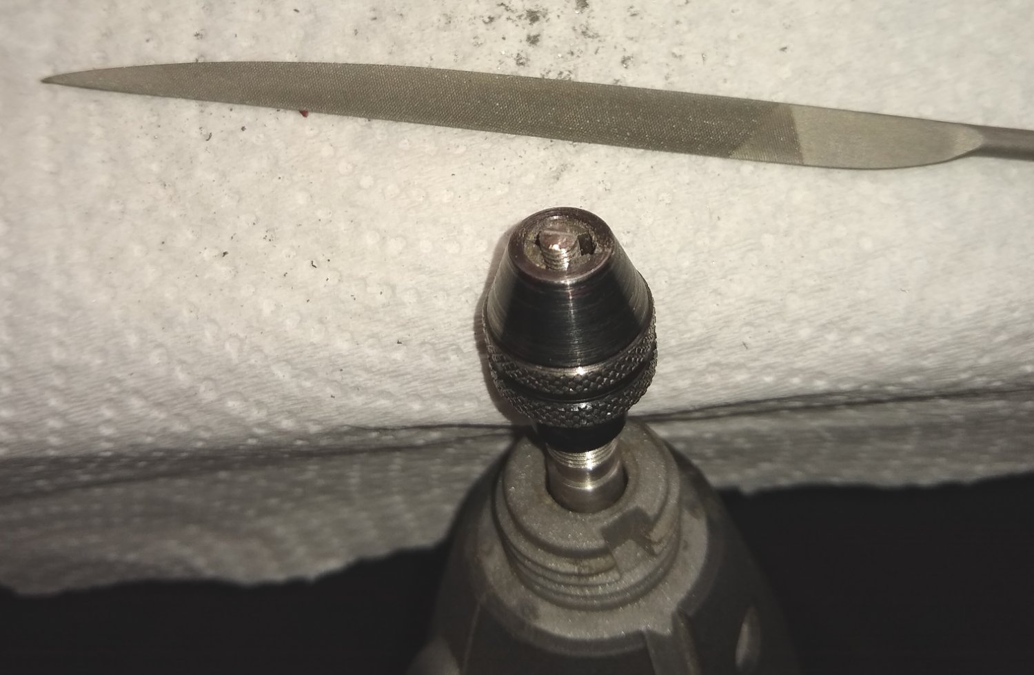
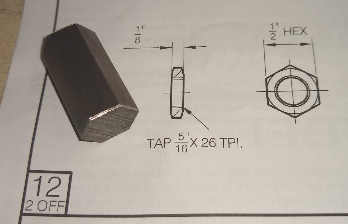
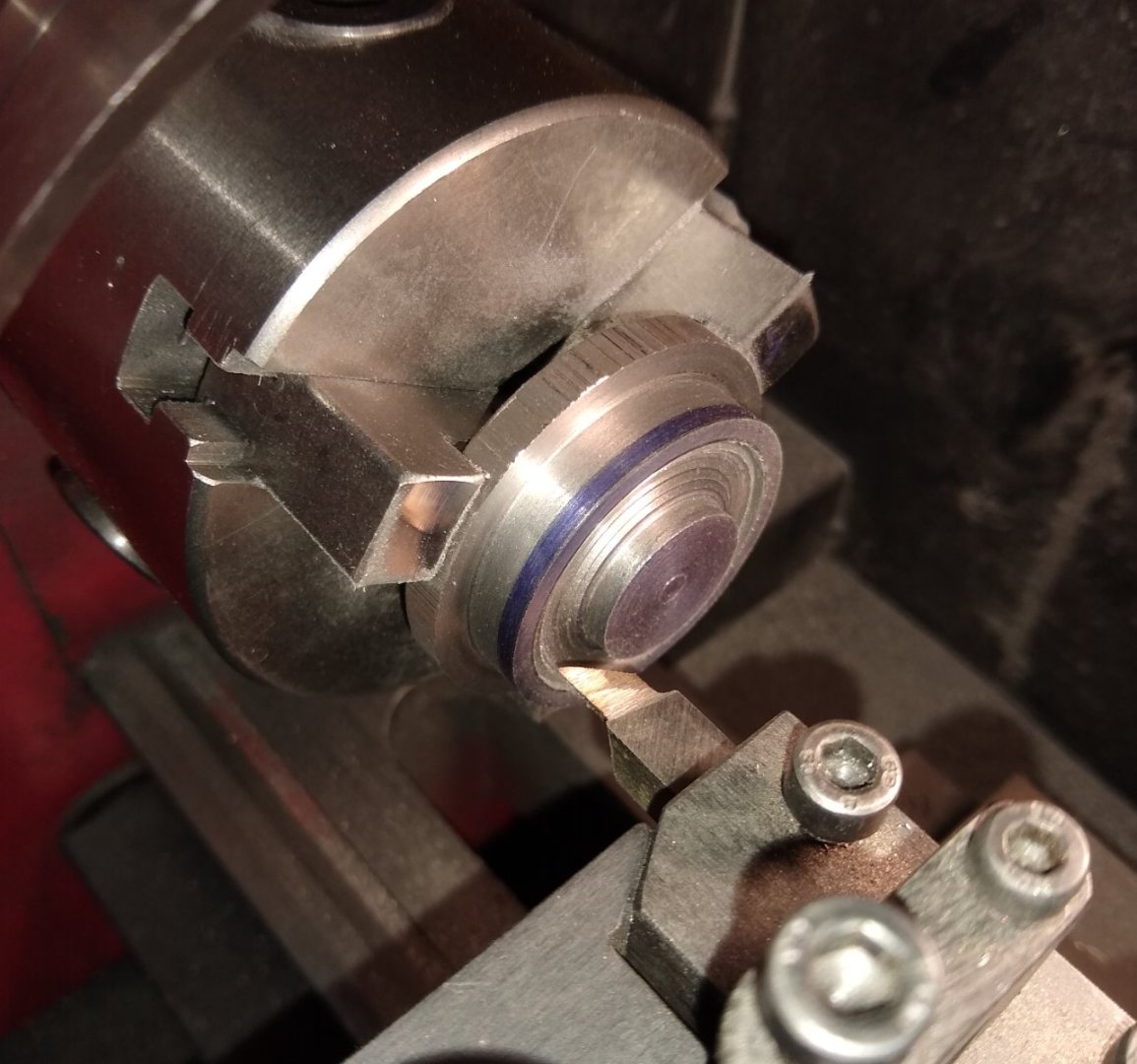
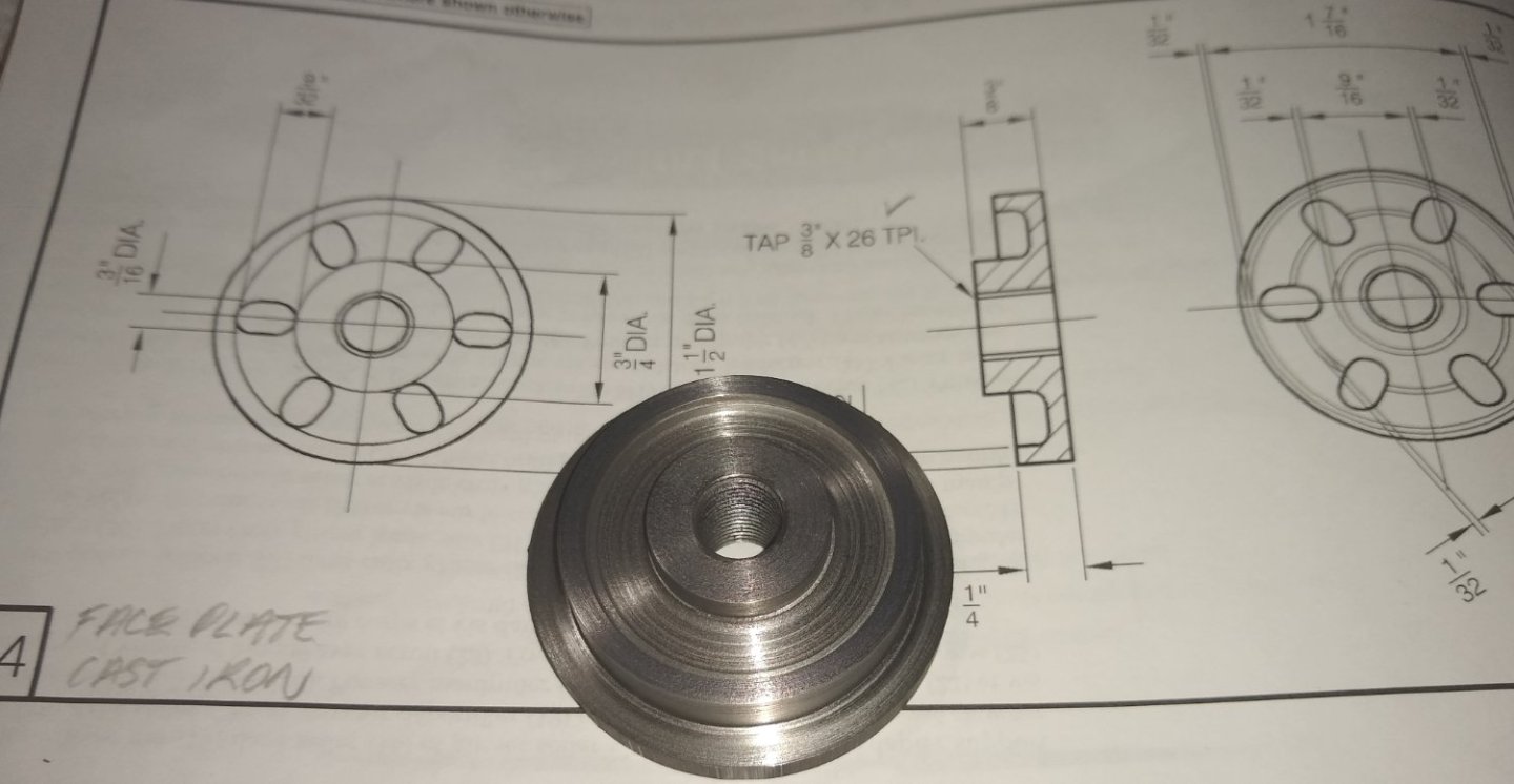
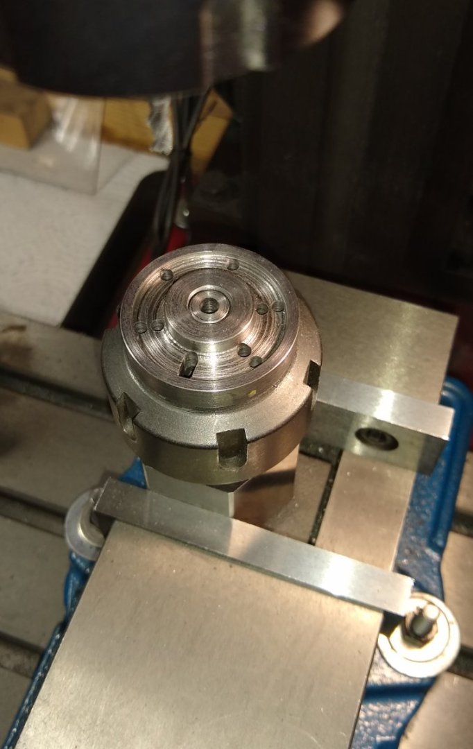
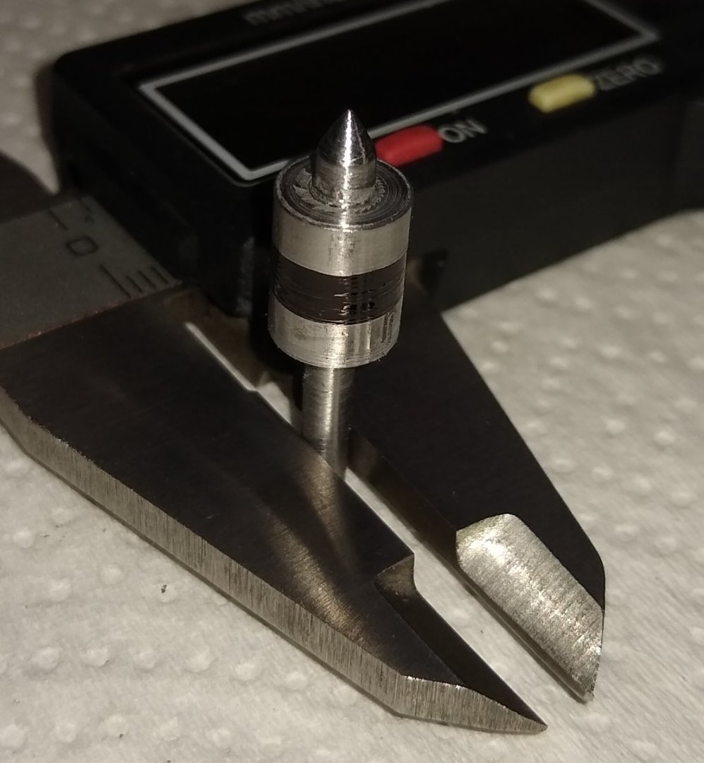
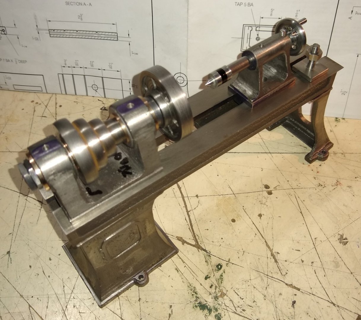
Hi all, Some more pics and info on the lathe build, relating to the Headstock and Tailstock. Below, a reminder of the Headstock parts. This week I firstly I made the two slim nuts (Item 12) that hold the Spindle on the headstock. A piece of 1/2" hex bar is supplied with the kit, and the nut manufacturing process is fairly straightforward. Firstly square off the end, drill and tap the thread, chamfer the nut corners and then part-off. Below, both nuts ready for screwing on to the spindle. The nuts are locked together leaving just enough gap for the spindle assembly to rotate freely. Next, the Faceplate, Item 14. The faceplate is used to securely hold larger and/or more awkward shapes than the chuck can accommodate. Machining one side of the cast iron faceplate. I had used a carbide tipped tool to remove the outer hard skin of the cast iron. Then I reverted to a HSS tool which could be ground into profiles that allowed me to cut in to the recessed corners of the faceplate. Below, one side of the faceplate finished, complete with the through tapped hole. The faceplate drawing shows six radial slots for clamps to use. The drawing slots looked a bit fat and chunky so I made them narrower. Below, the faceplate is held in a mill collet attached to a hexagon Stevenson block. The block is a simple way to index the six locations of the slots. I positioned the block to one end of the vice, sliding it up against a parallel held against the square vice sides. This ensured that every time I rotated the block 60 deg it always was in the same position relative to the milling cutter. I initially drilled two holes for each slot to lessen the workload on the cutter but in hindsight one hole might have been enough. The finished faceplate screwed onto the headstock spindle. Now to the Tailstock. Item 40, the tailstock body had been awaiting the delivery of a 9mm end mill to make a counterbore to accept the wheel end. The drawing called for a 3/8" (9.5 mm) counterbore but that would have left very little meat to tap the 5BA thread (item 46) in to....hence the slightly smaller 9mm cutter. Now on to the tailstock Wheel, item 44. I had to remember that the wheel shaft should be turned to 9 mm diameter rather than the drawings 3/8" (9.5 mm). Below shows the wheel being threaded for the tailstock leadscrew. The tap holder and associated parts have green paint on them to make sure they don't get separated into other tool drawers 🙂 The wheel turned around in the chuck and having the other face machined. Drilling the four holes in the wheel. This time a square Anderson block was used. The tailstock wheel is retained in the headstock by a 5BA grub screw (Item 46) with a small nipple on one end (that locates in a groove on the wheel) whilst the other end has a screwdriver slot filed in to it, with a knife needle file. Below it is shown held in a Dremel chuck - this was quite a handy 'vice' for a small part like this. The Dremel was also used to form the nipple by grinding it's shape with a square needle file. A 'live' centre was also made for the tailstock, Item 50. The drawing shows a fairly basic shaped centre so I tried to make it look a bit more realistically proportioned. A groove being cut in the tailstock leadscrew. Again a screw locates in the groove, this time stopping the leadscrew rotating but allowing it to move in and out as the tailstock wheel is turned. Finally an assembly pic of where we have got to so far. I've sat the tailstock T-Nut on the bed end ...it would normally reside inside the T-slot and clamp the tailstock to the bed. I've still some small parts to add to the tailstock but can include them in a later post. What's next?...well, it's either the Chuck or the Saddle + Cross Slide parts .... I think I might leave the Chuck till last, maybe. Regards, Richard


-
I went with a reamer. Yup, that's what I did, when it eventually arrived by post 😉 Richard
-
Welfalck, Yes, a boring bar is my go-to tool for straight holes. But with the hole diameter being quite small - 5/16" (8 mm), I didn't have a stiff boring bar small enough to fit inside that diameter. I do have some very small diameter home-made boring bars (eg 1/8" dia) but I felt the hole was too deep so the bar would flex, and the Bronze material was already proving quite tough to machine. Yes, it's a fun project and, as you note, enhanced by the generous side-discussions 🙂 Richard
-
Mark, Thanks also to you and EG. You both got me reading up on pulleys and belts and I now know interesting and useful new stuff I didn't know a few days ago 😉 It is quite a fascinating subject, simple as it may appear on the surface....curvatures/angles, belt materials, distance between pulleys, which pulley drives, efficiency etc etc . For example - https://www.plantengineering.com/articles/basics-of-belt-drives/ Richard