
HOLIDAY DONATION DRIVE - SUPPORT MSW - DO YOUR PART TO KEEP THIS GREAT FORUM GOING! (Only 44 donations so far out of 49,000 members - C'mon guys!)
×
Rik Thistle
-
Posts
864 -
Joined
-
Last visited
Content Type
Profiles
Forums
Gallery
Events
Everything posted by Rik Thistle
-
 Tom, Yes, I got my Full licence a couple of years ago and am lucky enough to have two long time friends who are very experienced and helpful Hams. They helped set up my VHF/UHF antenna and HF 'roan' antenna (ie wire hidden under the roan of my house). The HF roan antenna is OK'ish but being hard against the building struggles a bit. So I bought a Spiderbeam telescopic pole and have built up N7DDC's ATU. So will eventually have a 12m HF wire antenna in the garden. I have an ICOM 7100 (great Jack of all trades) and a Kyodo KG105 radios. I join nets on a Monday and Tuesday evening usually. I'm currently not that active in radio....ship building seems to have taken my focus ... I think I'm more of a 'builder' than a 'user'. But I will make an effort 'soon' to start exploring amateur radio a bit further. Your blog is a great mixture of interesting topics. All the best, Richard
 -
Vegaskip, Upon leaving the Army after WWI my Grandad was a docker in Leith, Edinburgh. And one side of my family comes from Leith. The Leith Docks warehouses are still intact but most have been coverted into shopping units and accommodation. The shoreline has changed a bit with new apartment blocks being built, shopping malls, restaurants etc. But the heart of Leith still remains the same. As does Leith Walk...apart from the monstrosity at the top, St James Shopping Centre. I have many happy childhood memories staying with my Granny and Grandad in Leith. All the best, Richard
-
Thanks Andrew - that makes sense. I'll attach all the clamps to a strip of wood covered with kitchen towel, for a few days. Regards, Richard
-
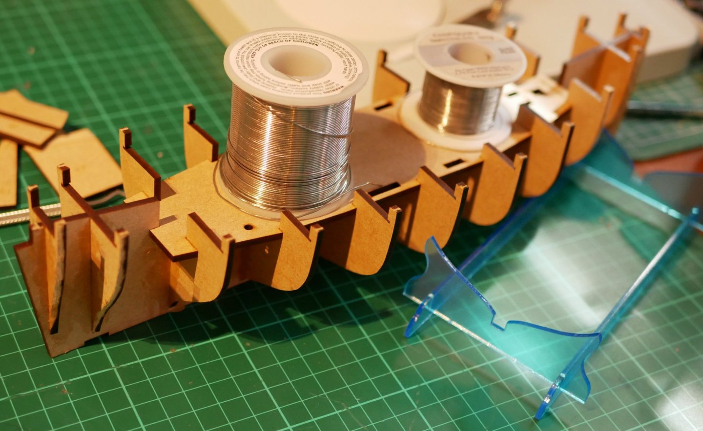
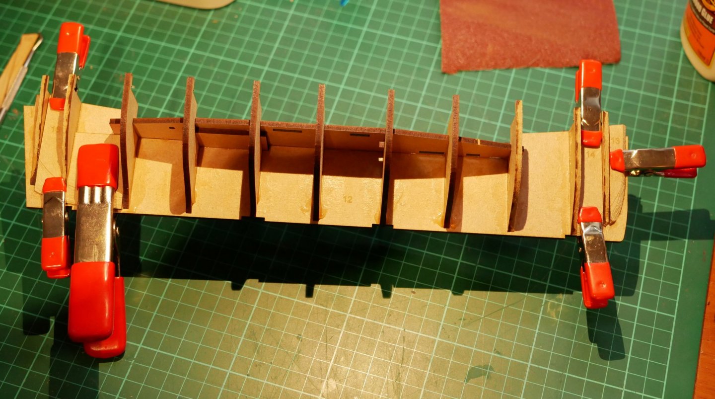
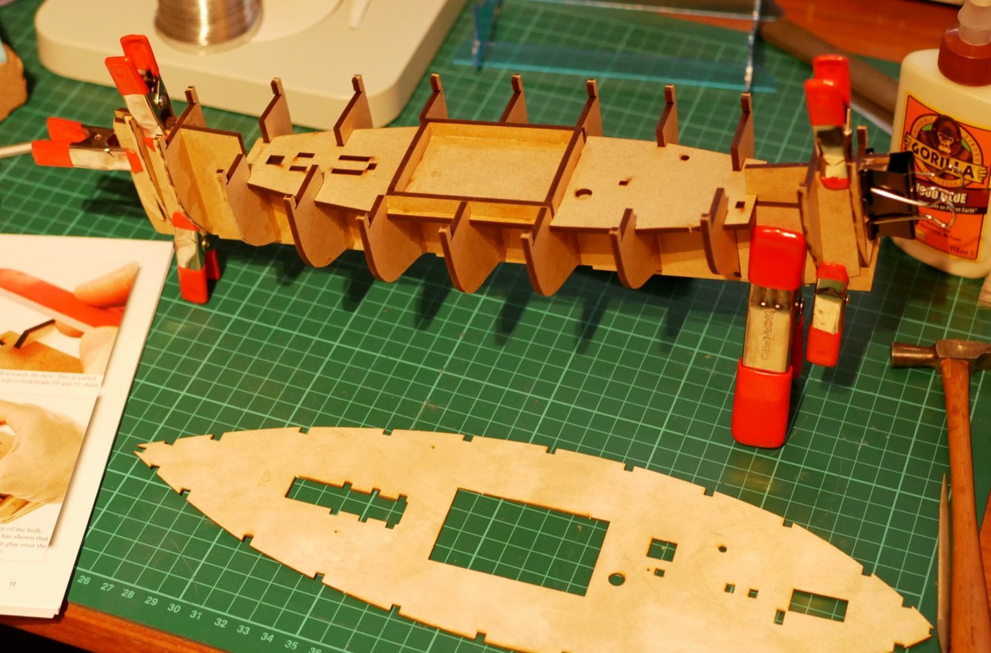
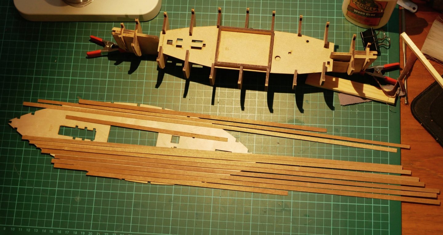
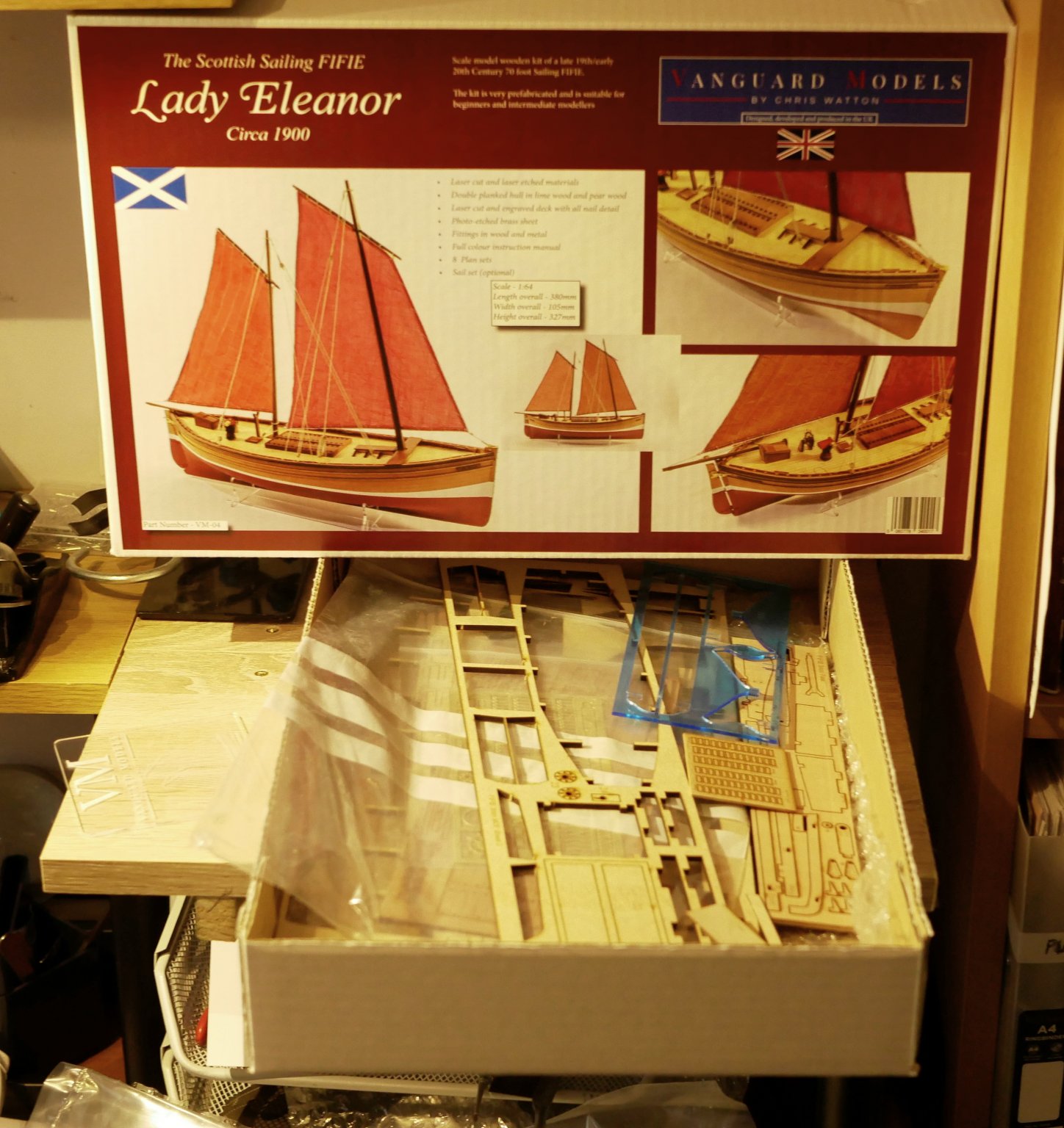
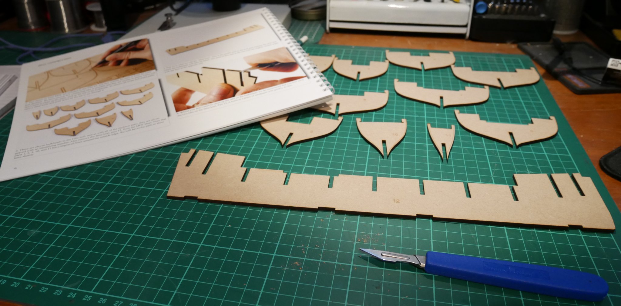
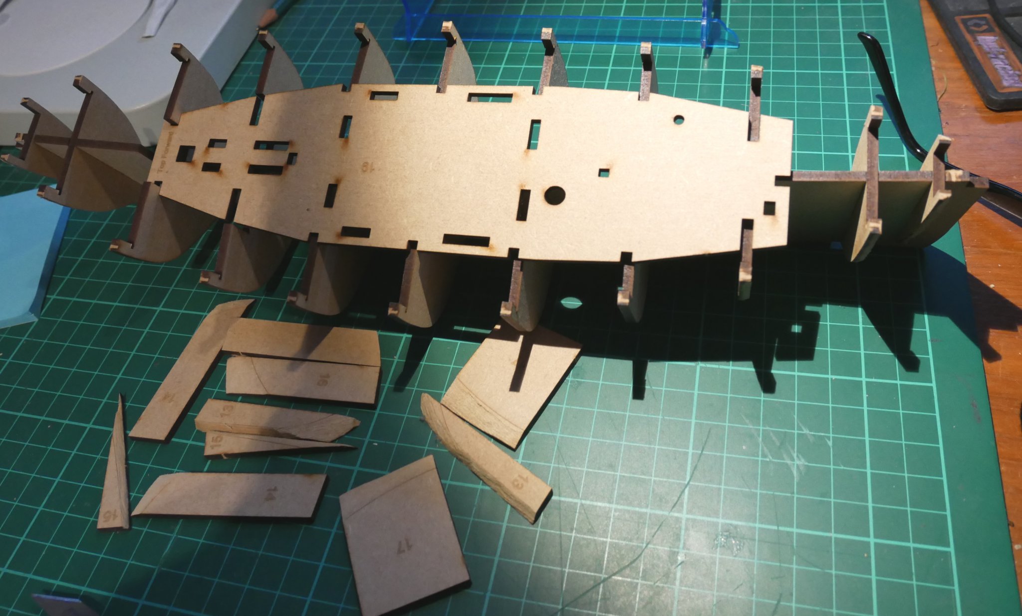
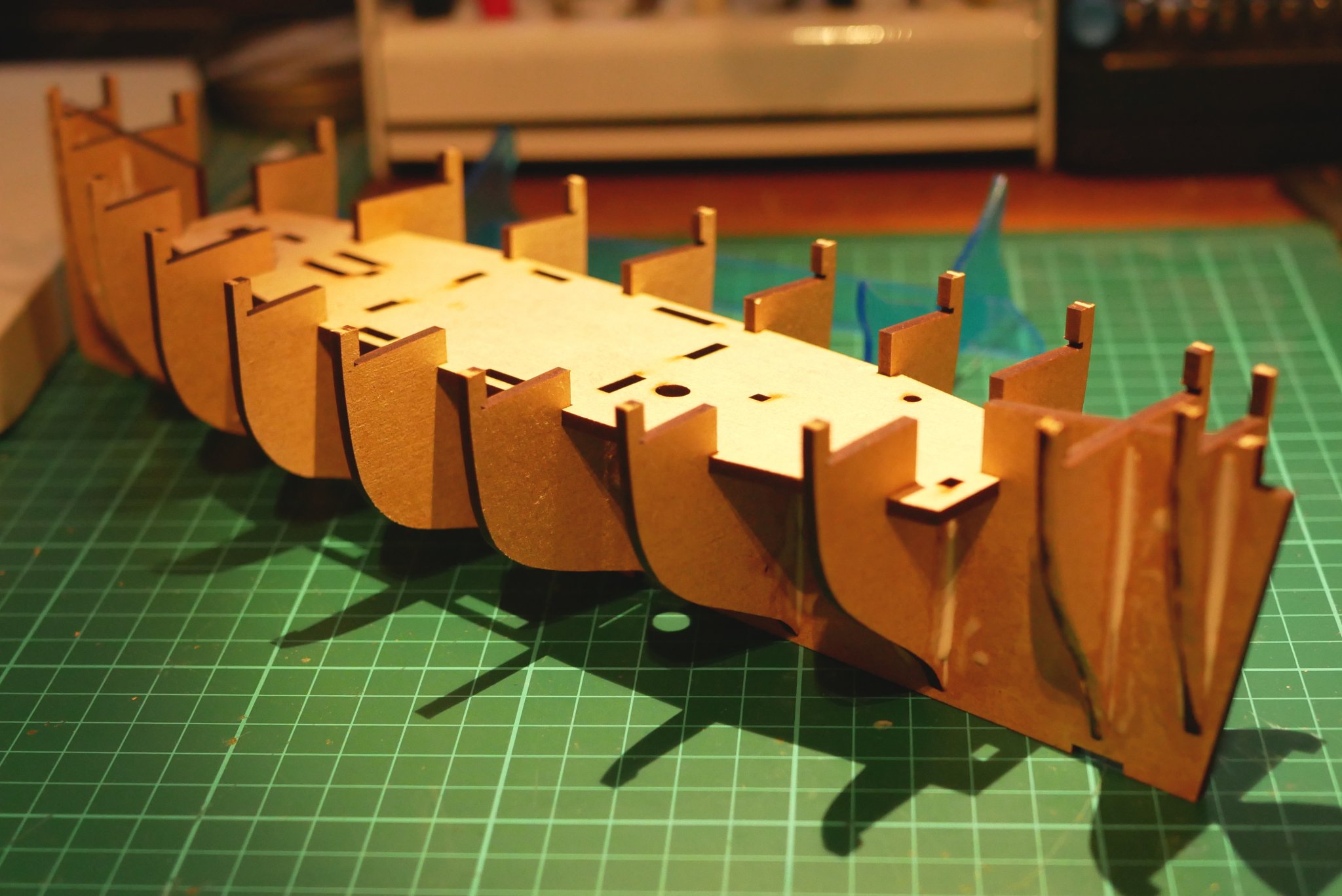
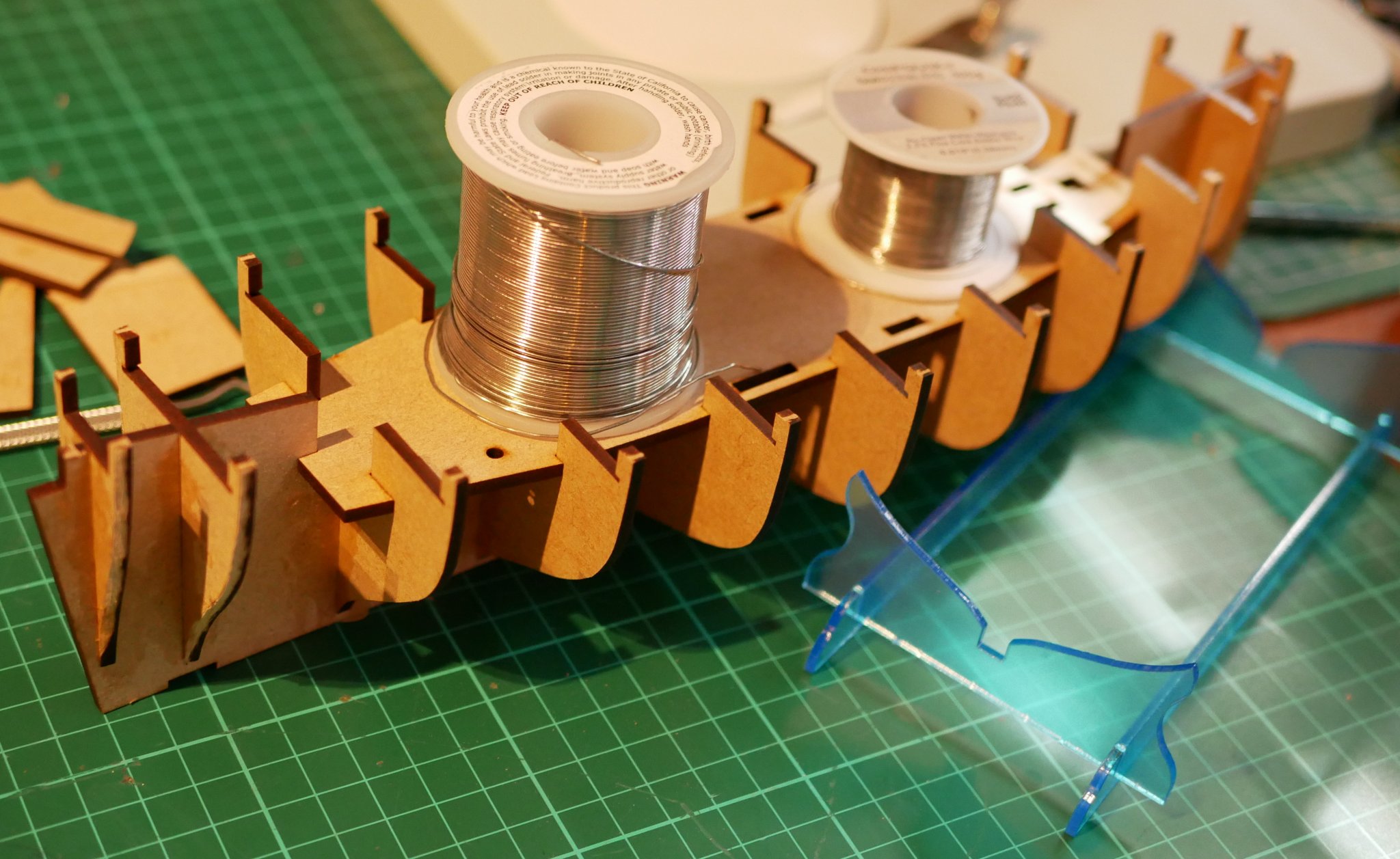
Hi all, The Lady Eleanor box arrived a couple of months ago. Well packaged and no damage during delivery. So, after finishing my Dallas Cutter a few days ago, I couldn't wait to start on my Fifie. I was also curious to see how kit parts design had moved on since my 25yr old Dallas had been manufactured. A quick check of what was in the box, read through of the Manual and Plans, and then on to sepearating the first parts from the wooden sheets. I have to say that there is a night and day difference between the 25yr old Dallas parts and Fifie parts. That's not to disparage the Dallas - it was good in it's day and maybe forced one to 'work harder', but the laser cut Fifie parts are so easy to remove from their sheets and fit together with astonishing accuracy. Below, some bulkheads beveled as requested and about to be fitted to the false keel, with Part 19 gingerly sitting in position. PVA (...too much!) brushed on to the bulkheads. Now the soldering procedure! Clamps holding the prow and stern parts in position. Note: The next day these new red clamps has left an oily stain on the wood - release oil from the plastic mould, I guess. I'll have to clean them all for any exterior work. Parts 21 & 22 PVA'ed into position, and the whole lot left overnight to set. Next day....now....I did enjoy putting the decking on the Dallas and I see Blue Ensign has done such with his build (https://modelshipworld.com/topic/24212-lady-eleanor-by-blue-ensign-vanguard-models-scale-164/?tab=comments#comment-712627). He's also done a lot more 'tweaks' that I'd love to also try but are maybe over ambitious for my current skill level. I did find some left-over decking (or hull planking?) from the Dallas that I might have enough of to deck the Fifie. So pondering now what my next move is regarding decking. In the meantime, I saw this short BBC clip on the Reaper... The Boats that Built Britain for BBC... https://www.youtube.com/watch?time_continue=53&v=-CsnfkP6kzI&feature=emb_logo I noticed the decking looks quite dark in the clip, as it does in these stills .... https://www.scotfishmuseum.org/blog/post.php?s=2020-07-09-protecting-the-reaper-during-lockdown-and-beyond Regards, Richard


- 49 replies
-
- 7
-

-
- Lady Eleanor
- Vanguard Models
- (and 1 more)
-
Ah, I understand now, thanks Chris. Richard
-
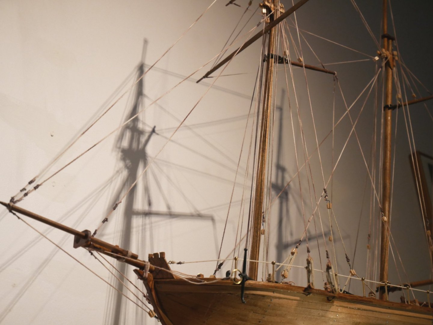
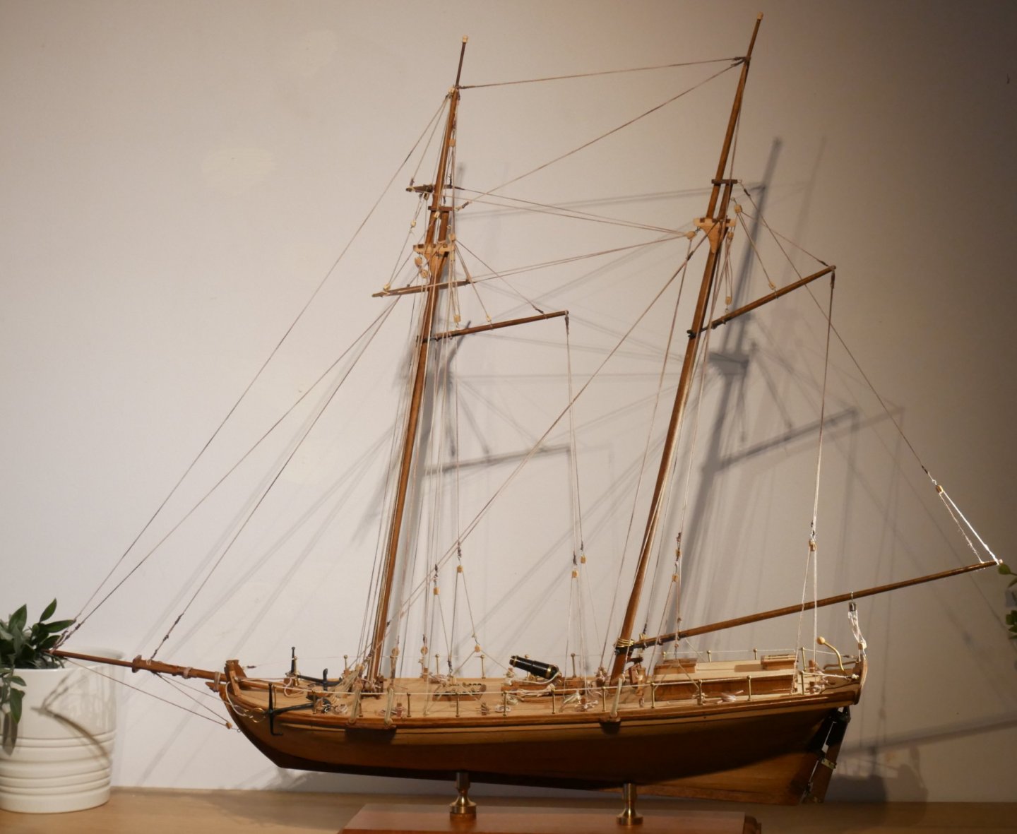
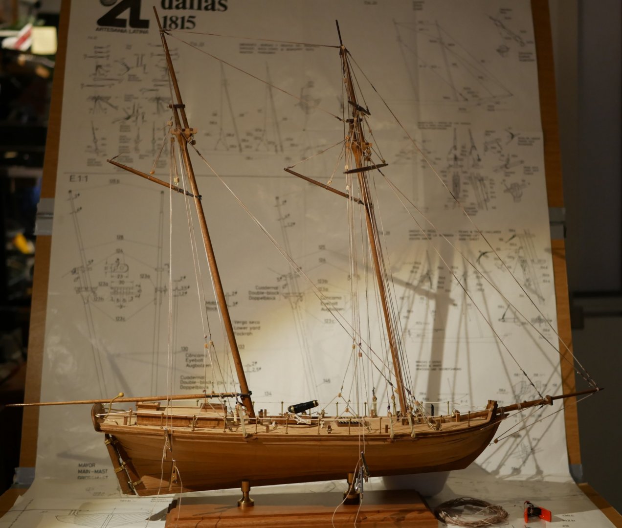
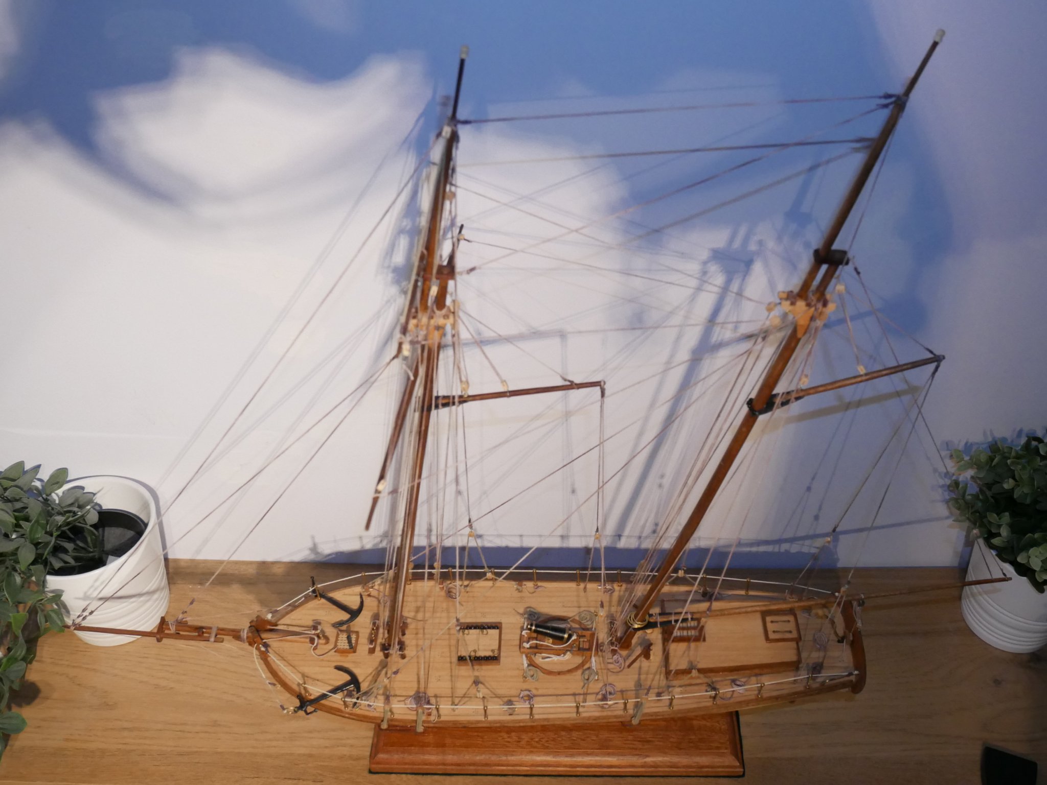
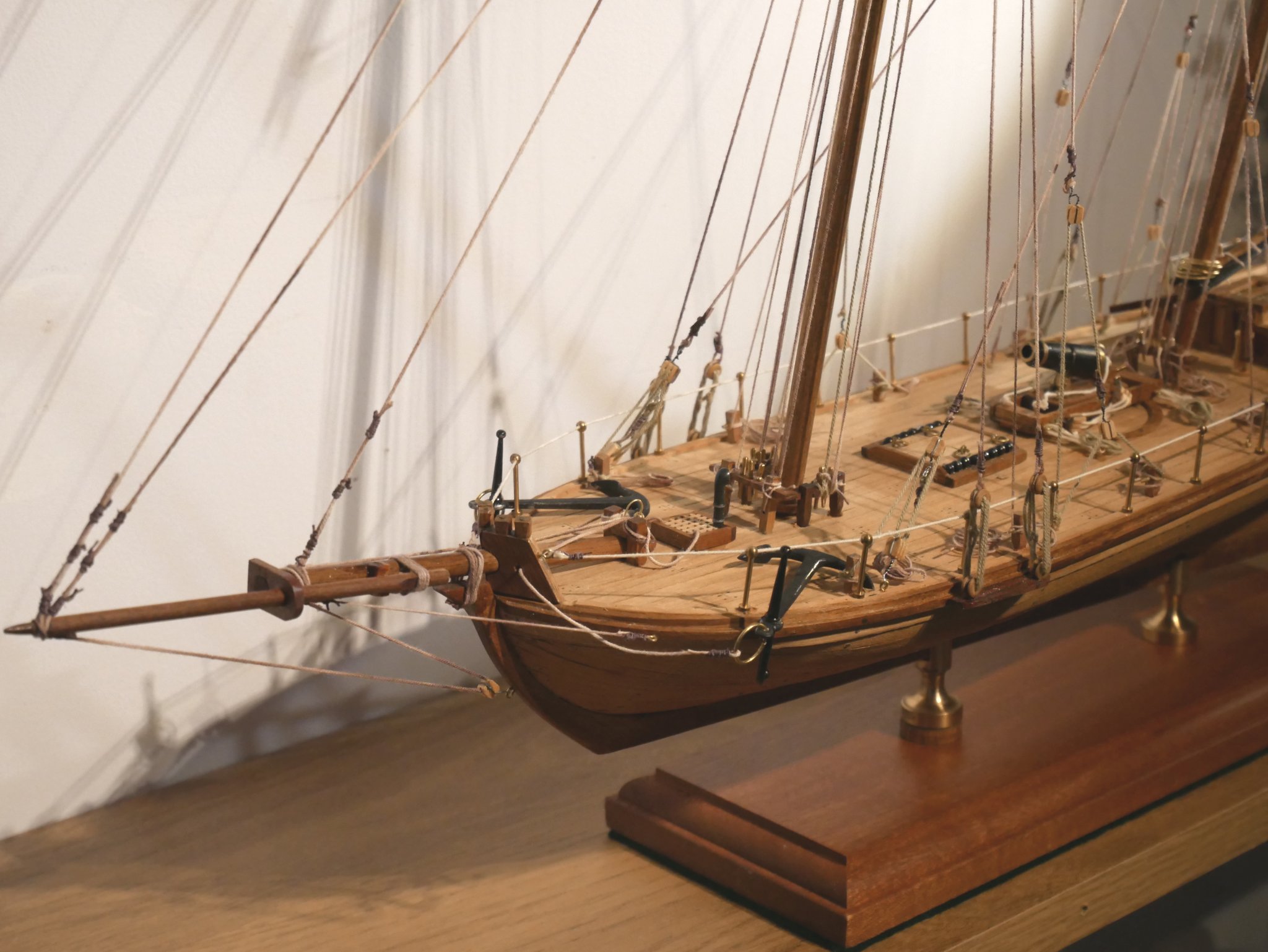
Hi all, I think I've reached the end of the journey with my Dallas Cutter ie Finished. There are still some areas needing 'looking at' eg no flag in the box so I'll make one up, some more rope coils to be added, and a bit of general tidying up. But this is as far as I'm prepared to take it for now. It's been a great learning experience and a multitude of mistakes made and some pretty rough corners cut. From above.... Looking up from the prow... Looking down at the prow area... The deck.... And ready to sail...into some green vegetation. Thanks to all for the useful comments along the way. Now to clear the decks in my 'shipyard' and make way for the Lady Elanor 'Fifie'. All the best, Richard PS: I tried to add 'FINISHED' to the title but I can't edit the title. Anyone know how to do that? Thanks.


- 41 replies
-
- 11
-
-
- artesania latina
- dallas
- (and 1 more)
-
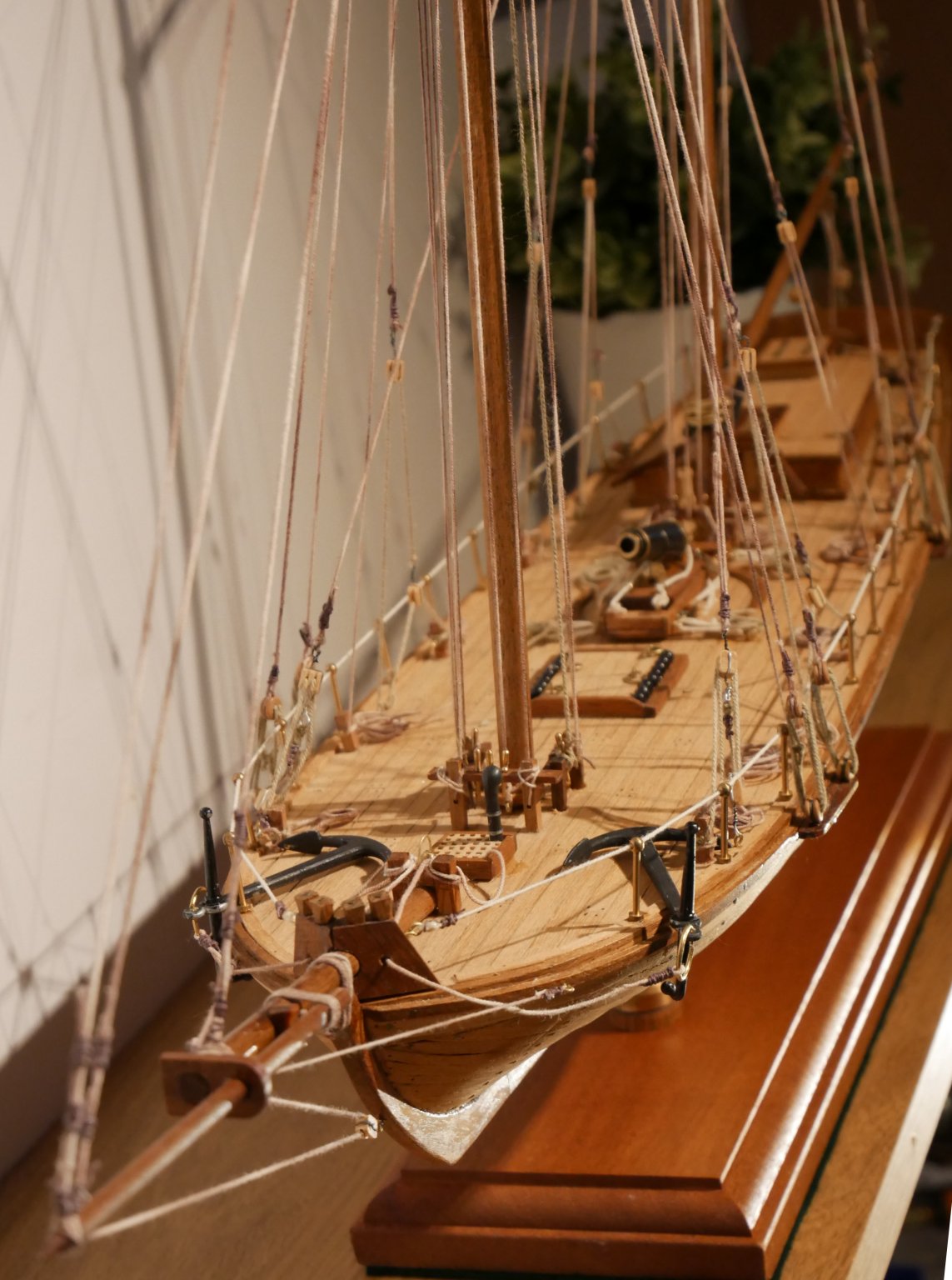
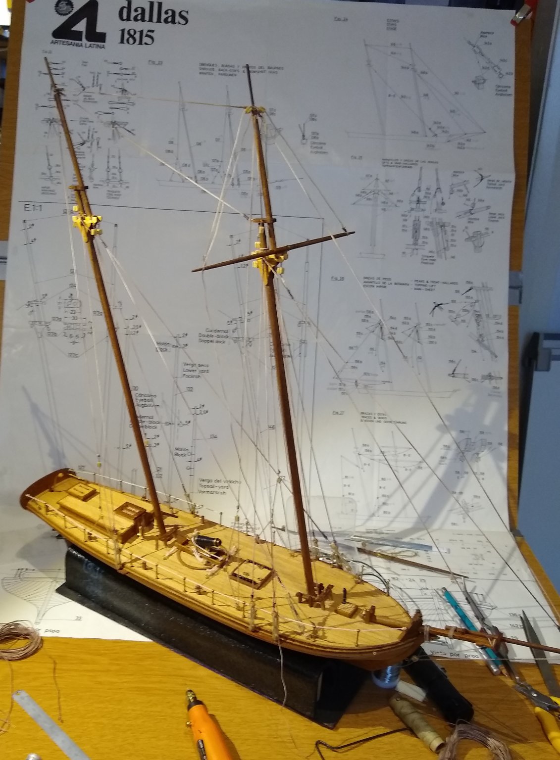
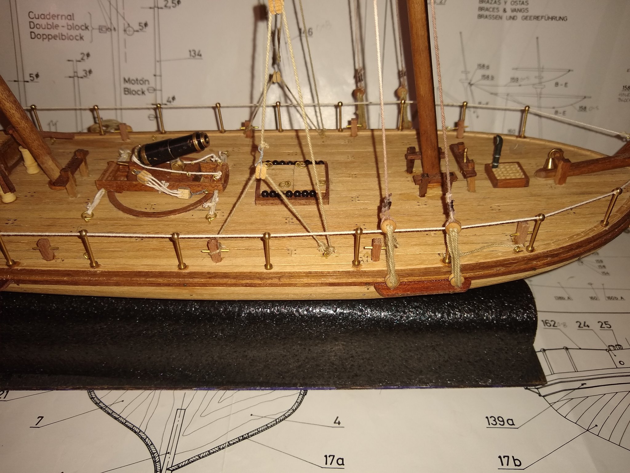
Hi all, An update on the Dallas. All the rigging is in place. Lots of tidying up still to do to it eg seizing on some ropes, coils of rope to be added where necessary, some rigging tensions to be adjusted to pull yards, booms etc into proper alignment and trucks for the tops of the masts. From above... Then next is adding the anchors.... I quite like the look of the Dallas. It is sleek lined, has a nice balance to it and is not an overly fussy ship design. Function over form. So I'm beginning to see the light at the end of the tunnel. It took a fair bit of will power to restart Dallas after the hull sitting in the attic for 25yrs, but doing at least a tiny bit on it each day has helped keep moving it forward. I feel I may have now found a new hobby :-) Regards, Richard
.thumb.jpg.3a005de0a082c162fc4a33a943c54440.jpg)
.thumb.jpg.455c81231474137604366fbc890ef92e.jpg)
.thumb.jpg.61275f601e177d5988ec130daa53854a.jpg)
- 41 replies
-
- 6
-
-
- artesania latina
- dallas
- (and 1 more)
-
'isopropyl alcohol' - ah, OK Louie. Thanks for the tip. I have a bottle of IPA in my shed, so will experiment with it on the Gorilla PVA glue I've been using on most of the ropes. I have Q Tips and also some small syringes (somewhere). I had initially used CA since it seemed a quick 'rope fix,' but quicly discovered it makes the ropes hard and leaves a mark. In parallel with my 'discovery', I was reading that many others on this website don't recommend CA as a primary fixing. Regards, Richard PS: I do like the self-sealing nozzle design on PVA glue containers these days. It's very effective at stopping the glue hardening inside the bottle, as well as being a reasonable dispenser. There is a current thread elswhere on this site discussing best methods for dispensing and applying PVA, that I've been following.
- 41 replies
-
- 1
-
-
- artesania latina
- dallas
- (and 1 more)
-
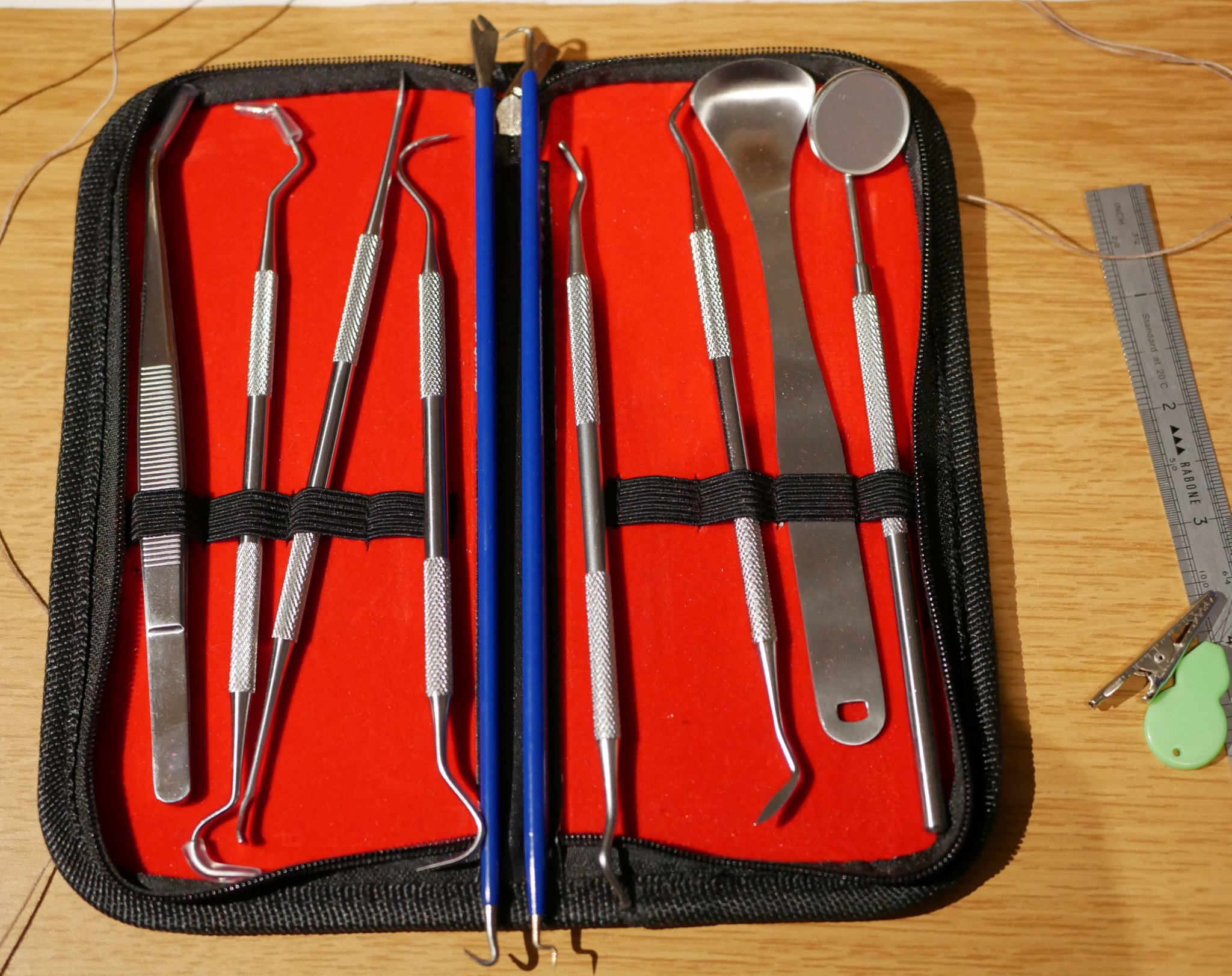
Hi all, Another short update. The rigging on the Dallas slowly continues. Learning a lot as I progress, and finding new tricks and dodges to hide (some) of my mistakes 🙂 I've also started fitting the Yards. ...and from above... To assist with the rigging I've bought a cheap set of 'dentist's tools', and two tools (blue ones) specifically designed for rigging... I'm finding as the rope density on the ship increases it seems to become exponentially more difficult to attach and route the next rope. The new tools help considerably. I'm also noting that taut ropes installed a few days ago become slacker as newer ropes are added. But I'm finding fudges to 're-taut' those ropes. All in all quite a steep learning curve for me. Those that rig ships such as Nelson's HMS Victory have my deepest respect! And there's not even any sails on the Dallas... another whole new ball game altogether. Anyway, still enjoying the pain but looking forward to finishing Dallas and moving on to the Lady Eleanor Fifie. Regards, Richard


- 41 replies
-
- 4
-
-
- artesania latina
- dallas
- (and 1 more)
-
Excellent! Thanks for the feedback B.E. And I'll have a dig around the other parts of the website for more info. Anstruther is a lovely, picturesque little town. St Andrews is just up the coast and, if you like golf, there are many wonderful golf links and inland courses to play on. Regards, Richard
- 261 replies
-
- 1
-
-
- muirneag
- vanguard models
- (and 2 more)
-
Hi BE, Looking forward to watching the build progress. I've got Vanguard Models' Lady Eleanor Fifie sitting impatiently in it's box waiting for my current build (Dallas Cutter) to finish. Living in Scotland, my plan is to visit the Scottish Fishing Museum in Anstruther once things quieten down and the Museum reopens. They have a restored fishing boat in harbour there, the Reaper. As an aside, I notice you have the Proxxon MF70 Milling Machine in your workshop. I already have their mini lathe and one day might purchase a mill. How to you find the Proxxon mill?...is it robust enough for model making....any strengths/weaknesses?...and can it take light cuts on brass....and even the lightest skims off (gulp) mild steel? All the best, Richard
- 261 replies
-
- 3
-
-
- muirneag
- vanguard models
- (and 2 more)
-
New member from Scotland, very old krabbencutter
Rik Thistle replied to Paul Carswell's topic in New member Introductions
Welcome Paul, I live in Scotland also and, like you, restarted a 25 yr old project (Dallas Cutter) back in March when CV hit. Once I got back into the Dallas build and found I was enjoying it, I ordered Chris Watton's Lady Eleanor Fifie fishing boat as a follow-on project. My plan is to visit Anstruther, once things become a bit safer, where there is a similar fishing vessel (Reaper) that has been restored by the Scottish Fisheries Museum Trust. All the best, Richard -
When I started on the Dallas Cutter (25 years ago) I wasn't aware enough to incorporate two captive nuts into the hull/keel area for the eventual mounting of pedestals. This week I received a base and a pair of pedestals (29mm high, slot 8mm deep x 5mm wide, with a 4mm appx through hole). The pedestals would need a means of fixing to the keel of the Dallas that didn't involve nuts inside the hull. Also, the slope on the keel meant that using two pedestals of the same height caused the deck to slope unnaturally. I turned a wooden 5mm thick spacer (on the right of the pic below) to lift up one of the pedestals to compensate for the keel slope, and stained it to match the wooden base. As for fixing the base to the keel, I threaded the pedestal with a 2 BA tap (https://en.wikipedia.org/wiki/British_Association_screw_threads) to match two suitably long, slotted head, countersunk machine screws. With a 1mm drill in a hand-held Dremel (I don't have a small, high speed pillar drill) I drilled through the pedestals' rears (and partially into the fronts). These 1mm holes are for accepting 1mm dia brass attachment rods - see below. As seen below, the Dallas was then mounted on the pedestals (now screwed onto the base) and using that same 1mm drill (now in a pin vice), I drilled into the keel using the existing pedestal holes as a drill guide. I then dry fitted the brass rod. The drill holes will aways be at the rear of the display so no one will see them. (Note: drill one hole first and then insert the brass rod in to it before drilling the second hole in the keel - to prevent the keel slipping out of position). Although the pic below seems to show there is still a bit of a slope to the deck it's isn't that noticeable in reality. The Dallas deck slopes upwards to the bow and stern, being horizontal only in midships. And the the holes etc will be towards the wall so will not be visible. I will also put a short 90 deg bend on the rods' external ends to give purchase if I ever need to extract the rods. I'll use a small dab of Evostick to hold the rods in position. I'll finish the base off by gluing green felt to the underside. Richard
.thumb.jpg.58739c81fae7a6e2207101535d0a559f.jpg)
.thumb.jpg.ce7a4cbd4efb59016d31c5f90ea916d9.jpg)
.thumb.jpg.cc9571e12eed167bad3d7a73bf26ddf8.jpg)
.thumb.jpg.3948f5464ecc2a1b3db7827951392b97.jpg)
-
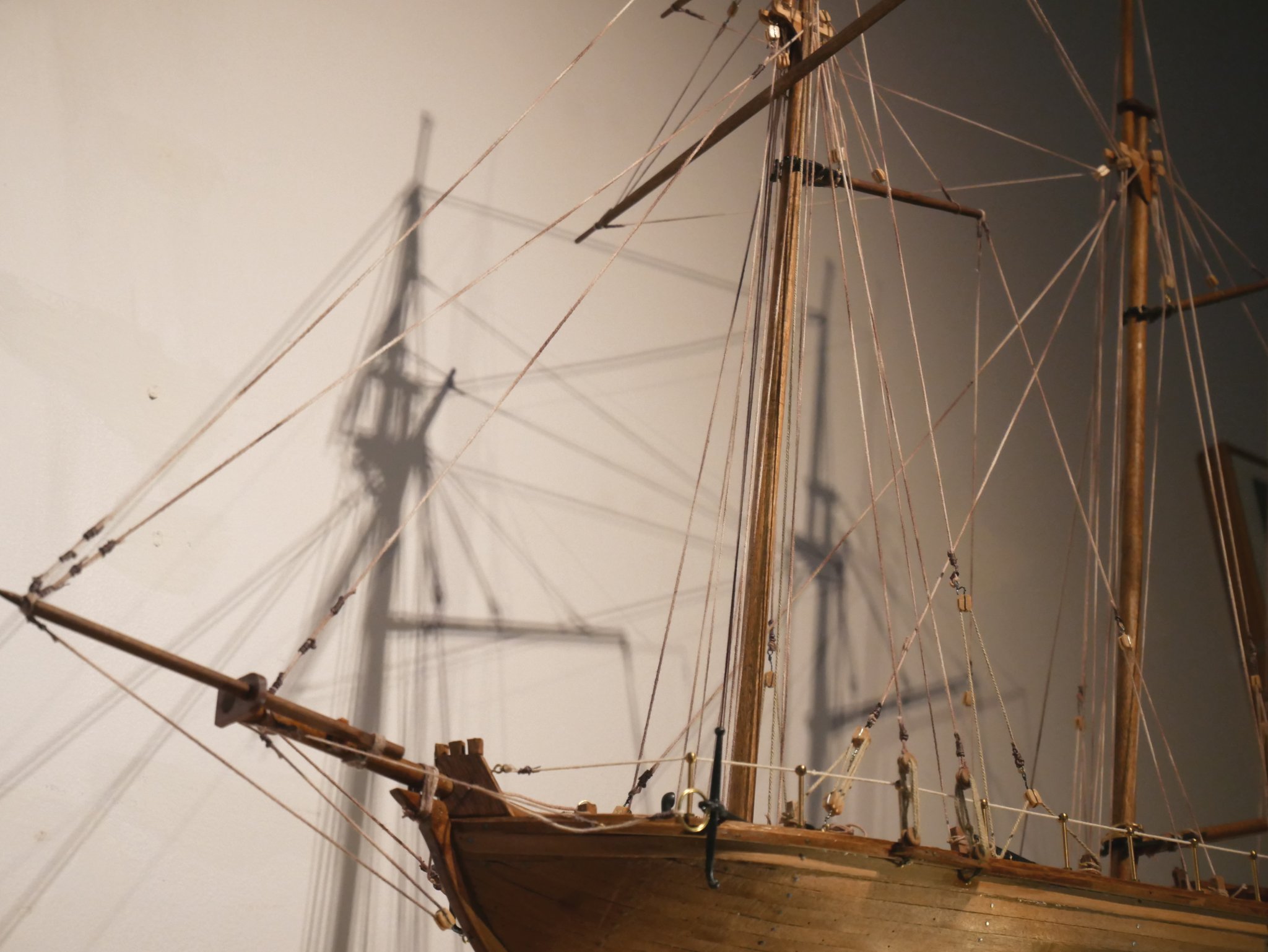
A quick update. Rigging going on. Some corners cut and mistakes made but from a distance it looks like the Dallas is slowly taking shape. The rigging drawing sheets, although they seem to contain all necessary information, are pretty smart at hiding crucial snippets of info in obscure places. I feel I spend more time studying the drawings/instructions rather than building...maybe that is the way it should be ...'read the manual first' ;-) Basic rigging in place. Topsail yard half way through being fitted. Close up of the rigging at the top of the two masts. Apologies for the photo quality - I'm using my mobile phone, mainly because it is handy and quick to transfer files. I'll dig out my proper camera for later pics. Richard
- 41 replies
-
- 5
-
-
- artesania latina
- dallas
- (and 1 more)
-
My National Gallery framed, 'medium' sized print (420mm x 325mm) arrived this morning. I went for the matt, no mount options. Total cost £70. Took 16 working days to arrive, which is perfectly fine considering it would have to go to the framers and the CV situation. The packaging was possibly the best I had ever seen. The print looks very good. One of the most colourful Turner prints I have. Very pleased. Now I need to make some space for it on my shack/shipyard/hobby room walls. Richard National Gallery link ... https://www.nationalgallery.co.uk/products/the-fighting-temeraire-print/p_NG524
-
This from the News page of their website... https://www.seawatchbooks.com/NewsForthcomingBooks.htm Summer 2020 It's been a wild first half of 2020. I've had 4 hospitalizations in the past year and am currently recuperating from some major surgery. Being an "old" sailor can be challenging!! On the good news front, Speedwell II is in the warehouse and available. This completes the series on this ship. On the not so good side, Rogers III will not see the light of day. With the book almost completed, the author quit, and I have nothing to publish. It is too bad because many people were looking forward to it. With the pandemic going on and the need to stay isolated, it is a great time to read books on ships and to work on models. Keep at it and stay safe. Richard
-
Byrne's saw accessories question..
Rik Thistle replied to CPDDET's topic in Modeling tools and Workshop Equipment
Slightly off topic, but Olha Batchvarov's prize winning model of Nelson's HMS Victory is quite stunning ... https://www.youtube.com/watch?v=6O6uBV0uThk ...as is the black background photography towards the end of the video. As a newcomer it was so impressive to see whilst at the same time a bit intimidating. However, in the Comments below the video she reveals it took her 4 1/2 yrs to build, so maybe.... Richard -
Hi Steven, After threading the deadeyes, some of them rotated slightly as I was attaching them to ropes above - that caused the three lines of rope between the deadeye pairs to cross over each other. I think the problem would be easily fixible (ie rotate them back in to correct position) were it not for the fact that I 'cheated' by adding a touch of glue to the rope knots. Anyway, I'll keep slowly working towards finishing the ship and then have a think about whether I need/feel like correcting my mistakes. It's all a big learning curve at the moment which, I guess, is part of the enjoyment 🙂 Regards, Richard
- 41 replies
-
- 1
-
-
- artesania latina
- dallas
- (and 1 more)
-
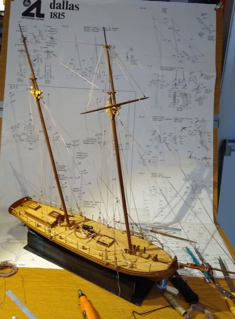
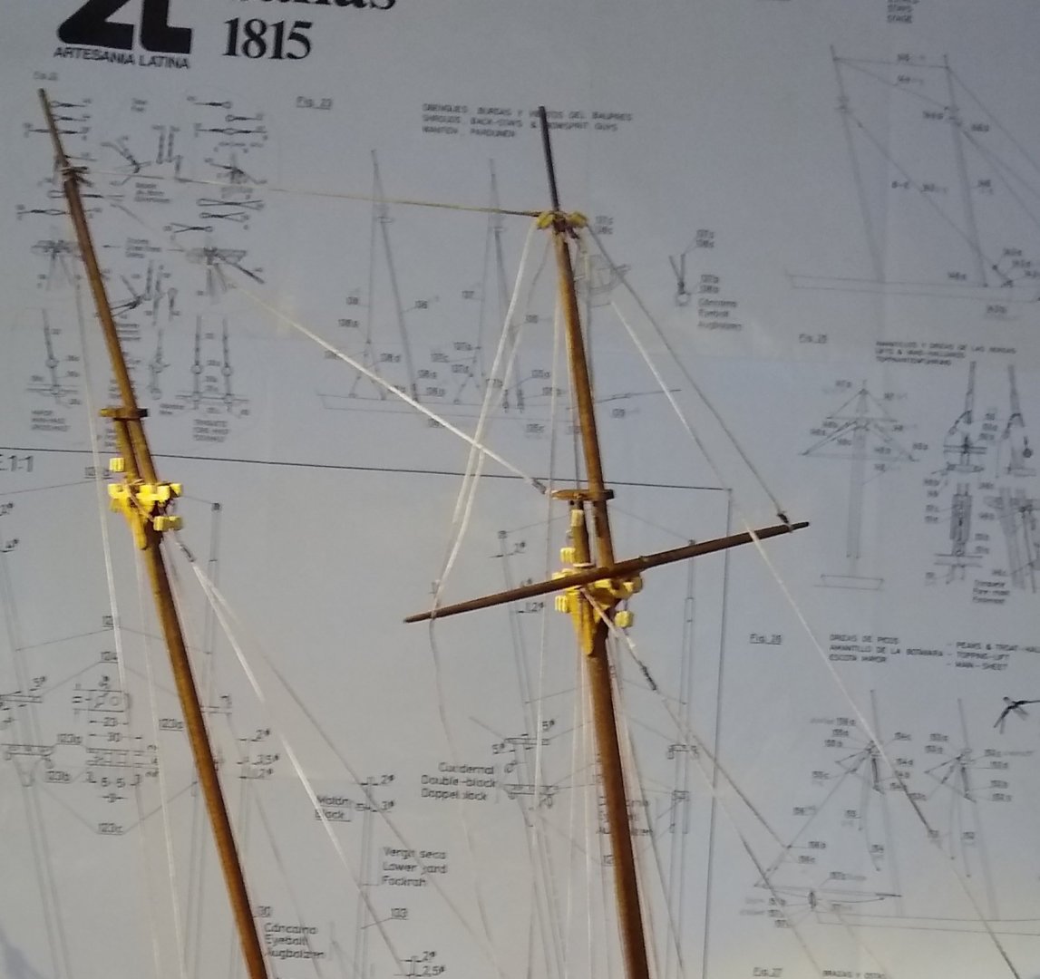
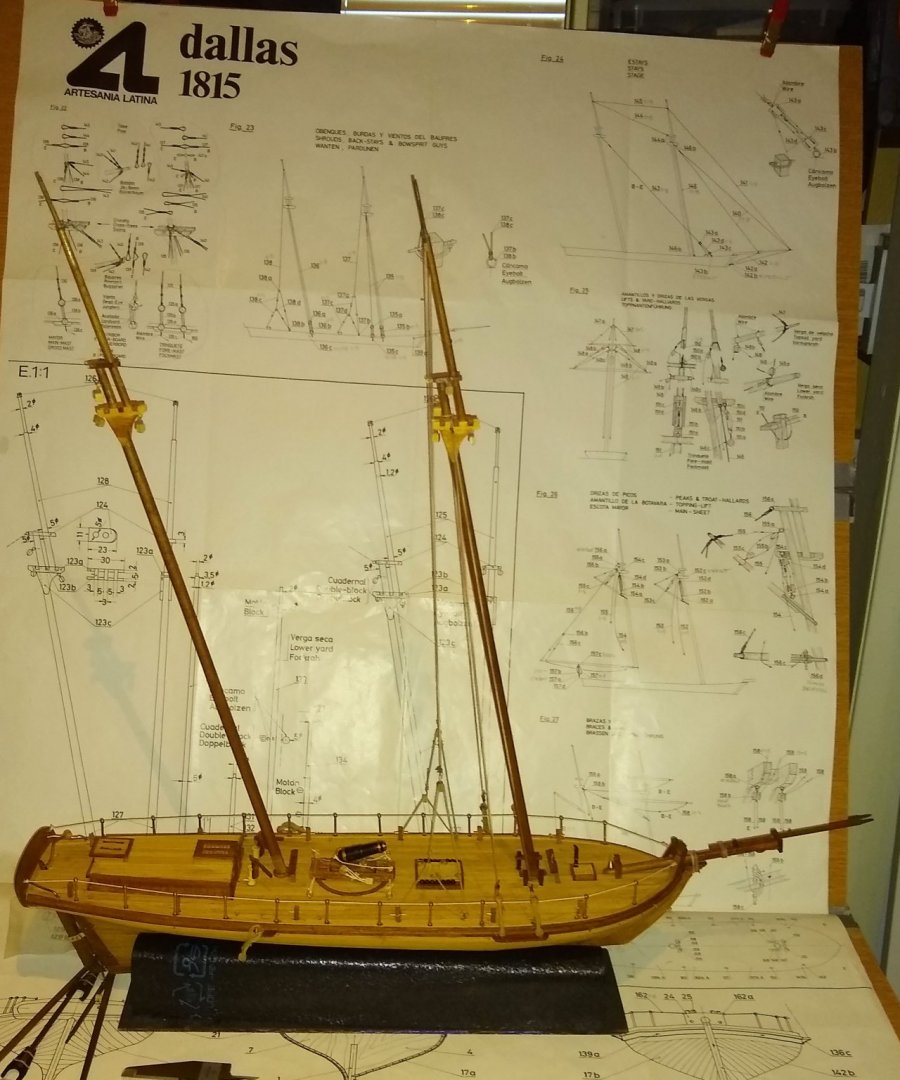
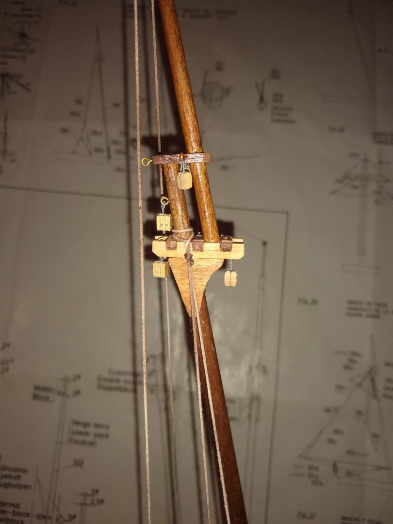
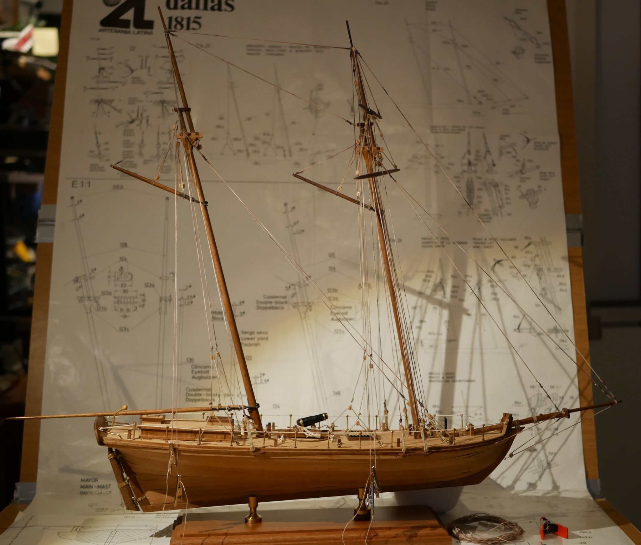
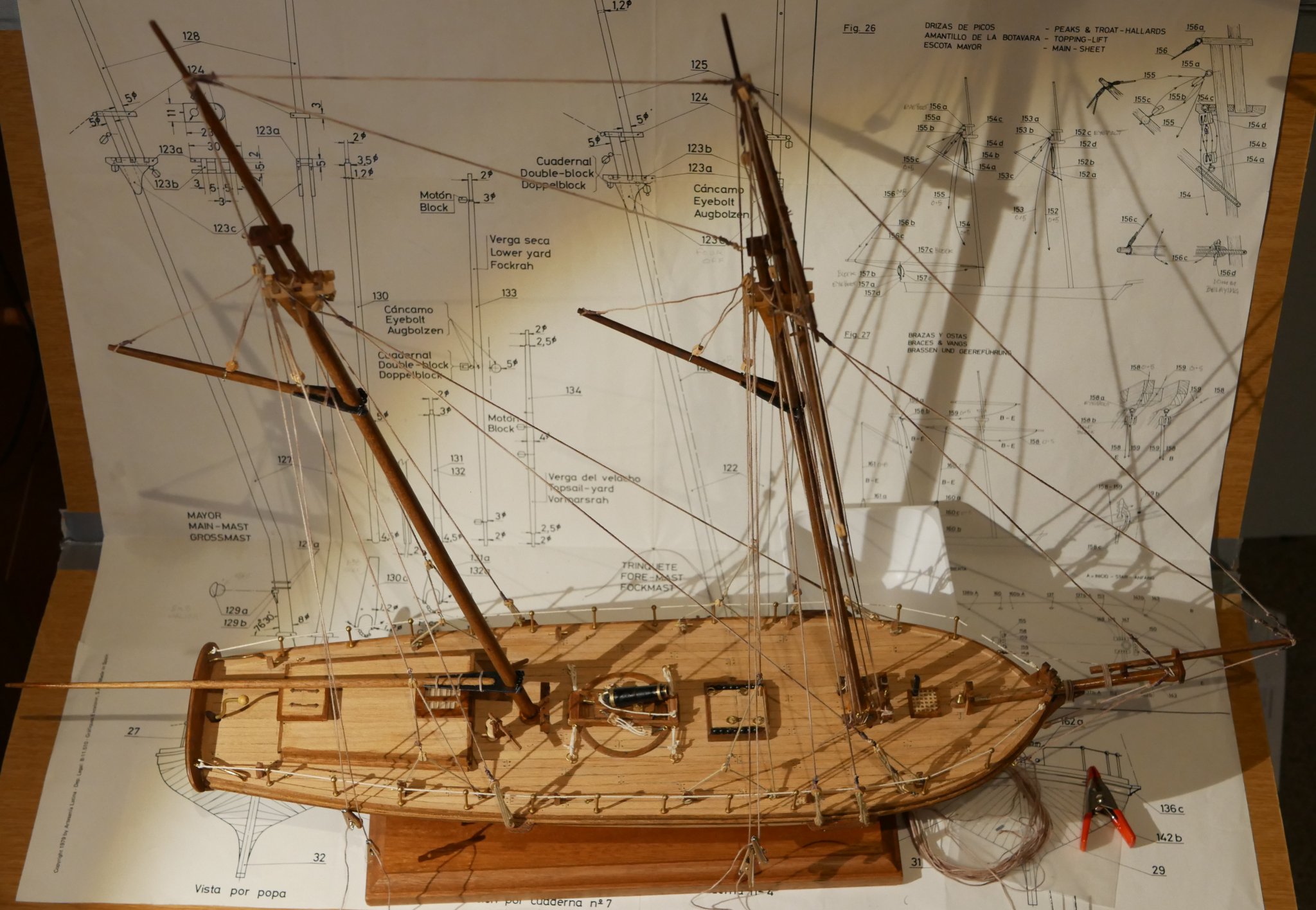
Hi, After assembling and fitting the masts and bowsprint/jibboom I've made a tentative start on the rigging. Yup....another whole new set of skills required for the rigging. RichardG was kind enough to advise I read up on 'seizing' and I have had a go on some of the ropes, but there are so many.... Anyway, here's 3x pics of the little progress made since last time. Masts ect glued into place ...main mast at 76 deg 30 secs and foremast at 79 deg ....with a bit of luck. The foremast has the only rigging done so far. Close up of some rigging. Some seizing on some of the ropes but not on others (but maybe later). Deadeyes have rotated so ropes look a bit twisted - will try to rectify. Close up of the upper section of the foremast. That's all folks, Catch you soon, Richard

- 41 replies
-
- 6
-
-
- artesania latina
- dallas
- (and 1 more)
-
Laying out plans in a smaller workshop
Rik Thistle replied to alde's topic in Modeling tools and Workshop Equipment
Hi Al, My rough and ready (but flexible) solution is to use 3x pieces of hardboard duct taped together. 3x pieces, so that they can be easily folded up for storage. Side view of my Plan Holder sitting on a rotating chair. The plan is held in position at the top by two clips. The natural fold at the bottom of the plan can be made to coincide with the lower hardboard join by adjusting the clamping position of the plan at the top. There is a piece of sheet metal behind the top two sections of the holder to stop the top section flopping backwards. A piece of 6mm thick plywood (or similar) would be just as good. There is duct tape on both sides of the 3x joins. The tape was added whilst the 3x pieces of hardboard were folded against each other rather than the 3x piceces lying flat on the floor...that stops the tape tearing when the 3x pieces are folded for storage. The rough side of the hardboard may need additional stapling to stop the tape coming off. The plan holder also acts as a temporary 'workbench' and is a bit lower than my desk (so easier to work on mast ropes etc) and the chair can rotate appx +/- 90 deg for slightly easier access to the rear of the model (but not as good as a proper Lazy Susan). I wouldn't leave the ship sitting on the holder 'workbench' unattended if there are other people using the room since it is quite easy to nudge the holder's corner as you move past it. Regards, Richard.thumb.jpg.bff7bb8dc3f3299b6703a6b688f4c3f2.jpg)
.thumb.jpg.f16c94f87b729d427cd73a3966e1eecd.jpg)
-
Richard, Ah..... that's what I've been looking for. Many thanks. 'Seizing'...another new word for my rapidly growing shipbuilding dictionary! Google has thrown up pages of results...time to start reading ;-) All the best, Richard
-
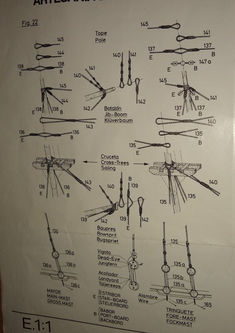
I may have figured out the knot question. If I look at the Dallas knot drawing with a magnifying glass it looks like the main rope (say 145) has it's end looped back on itself, then a seperate piece of rope is wound round the original rope's two diameters to hold the loop firm? Richard
- 41 replies
-
- 1
-
-
- artesania latina
- dallas
- (and 1 more)
-
Jorge, I got the same lathe a few weeks ago. Very compact and good for what it is. Agreed, the live centre is very good. A little slop in the tailstock, and my tool rest also had a very rough finish....but a bit of filing and fine emery cloth soon polished it up. All the best, Richard
-
Hi guys, I wonder if I can seek some advice regarding 'knots'. I'm about to start attaching lines to the masts etc and tie off those lines. The Dallas drawing sheet below shows the various knots used.... I've had a look at https://www.animatedknots.com/complete-knot-list .... but can't see anything relating to how the 3x knots (145, 144 and 138) in the top left corner are made. The first two look a bit like a noose slip knot but I don't imagine ships used slip knots? Any thoughts or advice on how to make 145, 144 and 138? Thanks, Richard
- 41 replies
-
- 3
-
-
- artesania latina
- dallas
- (and 1 more)


.jpg.93847ecf5cf8571267b405d9f69f3a6f.jpg)
.jpg.afd813a77118ad95f658d5ce10c5c012.jpg)
.jpg.28ab5cf17d5ffb02ea09798faf2c29a1.jpg)
.jpg.832ac1662f17088edc758d23632d677b.jpg)
.jpg.02611d87fb574269a6fd50110a880db0.jpg)
.jpg.7cfc0a87ea05380f5062ed9911470e58.jpg)
.jpg.36cc03d6c4afb144374396a0e85f26db.jpg)


.jpg.b8314a0005c51d19e159b616af88e0af.jpg)
.jpg.d756ac3aceb5465f04c0b821d0bc16ba.jpg)
