
yamsterman
-
Posts
550 -
Joined
-
Last visited
Content Type
Profiles
Forums
Gallery
Events
Everything posted by yamsterman
-
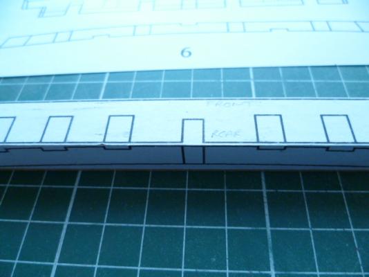
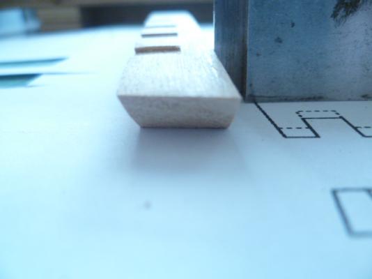
Hi don Great to see someone else building the Washington galley.....a nice introduction to a fully framed pof hull. I did have to study the plans very carefully.....the practicum is a suggested order of building only and didn't give any measurements. With regards to the keel I measured it as 3/16 inch thick (moulded dimension) by 7/32 inch in height....this was then cut on the Byrne's saw. The hog or rising wood that the frames are notched into was made as a seperate piece and again cut from 3/16 inch wide piece but 3/32 inch in height. The scores are 1/4 inch wide for the frames and each score is exactly 9/64 inch apart and 1/32 inch deep. All other components for the stem are cut from 3/16 inch stock.....photocopy the relevant bits from the plans and cut out to use as templates. The deadwood fore and aft were cut from several individual pieces of 1/8 inch stock. The stern post has to be cut from 1/4 inch stock as it tapers from its head to where it joins the keel. The false keel was also cut from 3/16 stock 1/16 inch thick. Hope this info helps Cheers....mick
- 504 replies
-
- 2
-

-
- washington
- galley
- (and 1 more)
-
Hi Nils Beautiful and very graceful hull.....looking forward to the "skin" going on! Cheers....mick
- 2,625 replies
-
- 3
-
-
- kaiser wilhelm der grosse
- passenger steamer
- (and 1 more)
-
Hi Patrick Wonderful stuff as usual! Very atmospheric shots outdoors......can't wait for the next build! Shall be lurking around watching and waiting....inbetween trying to do some modelmaking.decorating,building furniture for a colleague at work etc etc!!!! Cheers..,mick
-
Hi Johann A small work of art to reside next to a much larger work of art.!!! Astounding and wonderful craftsmanship......my hat is well and truly off sir!!!! Cheers....mick
-
Hi don Search for engineering tools or try mitutoyo,Moore and wright,starrett etc Cheers....mick
- 504 replies
-
- 2
-
-
- washington
- galley
- (and 1 more)
-
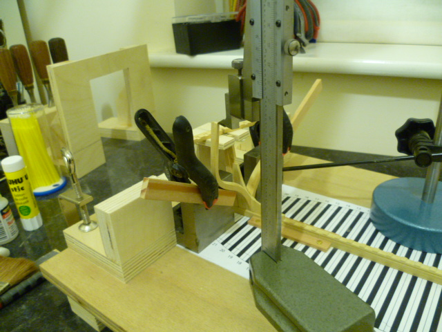
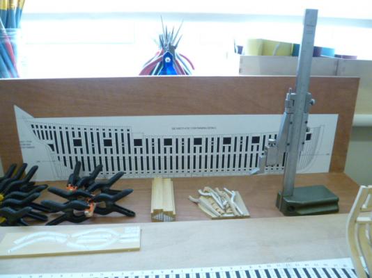
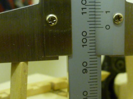
Hi don The vertical measuring device is a mitutoyo vernier gauge fitted with a carbide scribing blade. To buy one new would probably give you palpitations!! These gauges are primarily designed for the engineering industry for use on a surface plate in either inspecting components or for marking out. This one was given to me some time ago buy an engineer I work with. Probably the best place to look is on eBay.....I recently brought a brand new Moore and wright micro meter depth gauge for 1/10 of the catalogue price plus a couple of other mitutoyo items. Hope this helps Look forward to following your Washington build Cheers....mick
- 504 replies
-
- 3
-
-
- washington
- galley
- (and 1 more)
-
Hi Greg I did think about leaving all the gun ports till after but it struck me as more difficult....and being ham fisted at times I'd probably break a frame! So I decided to follow the practicum which recommends cutting the mortices as the frame is being built. The planking extends to one plank below the sale and all the planks up to the sheer plus the internal planking from deck level up.....so I guess there is a margin for a small error. As this is the first complete hull I've attempted in p.o.f style I've elected to follow the practicum and not try to be clever. Small steps!!! Hopefully this will lead to hms echo and ultimately hms euryalus.......with a few other practice pieces in between , increasing in complexity to further enhance my journeyman skills. Thanks for looking in Cheers....mick
- 504 replies
-
- 2
-
-
- washington
- galley
- (and 1 more)
-
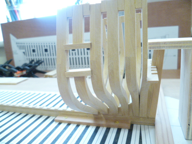
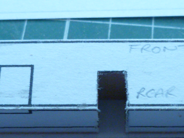
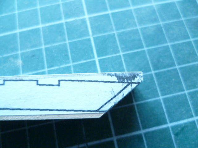
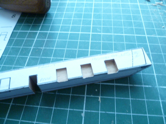
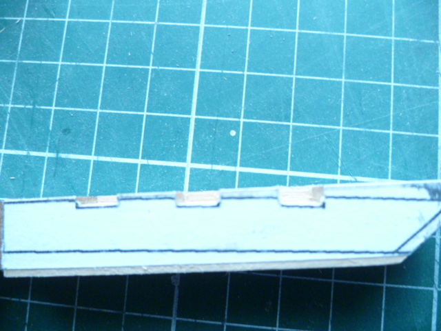
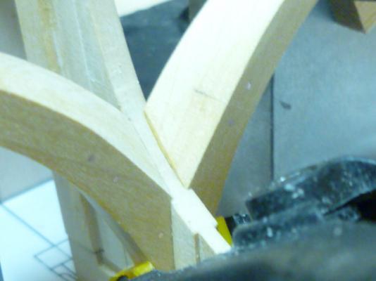
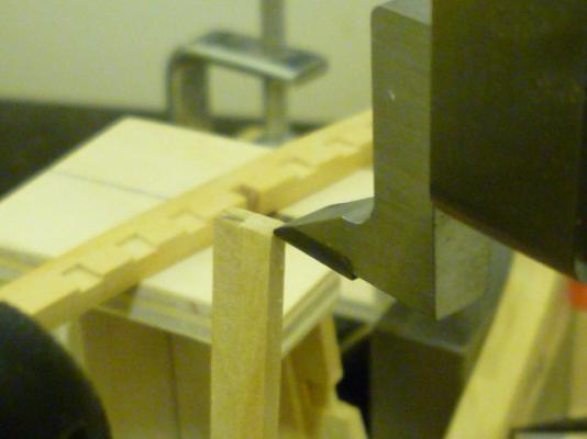
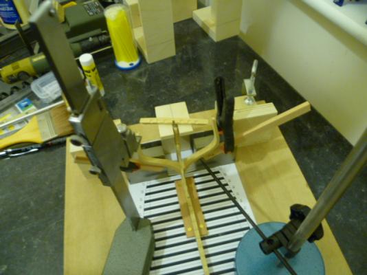
washington galley part 7.....stern framing hi all been a busy little bee making frames. the aft most gunport has now been framed. all frames have been left slightly over length....i will mark in the sheer and trim the frames at a later date. you will see from the photos that i have been trying to ensure as much accuracy as possible. however the top of the lower starboard gunport sill is approx 0.28mm lower than the port sill. in my book this is accurate enough! im not sure what tolerances the original shipwrights would have worked too but this difference equates to about 1/2 inch in real life. ive also now started to construct the first two half frames at the bow. you can see from the photos how much offset there is between the front and rear components of the frame.....the bevel when cut will bled all of that in. i have also ganged up ablock of 1/8 inch stock ready to cut the hawse pieces at a later date. anyway photos enclosed for your perusal...comments....critiques....most welcome cheers....mick


- 504 replies
-
- 12
-
-
- washington
- galley
- (and 1 more)
-
hi steve welcome to the washington galley project!!!! the milling machine i use is a micro mill/drill and matching x/y table from the seig(chinese manufacturer) machine company. in all fairness its not a bad machine,cast iron construction,belt driven with two speed ranges and coarse and micro feed. you can knock out the tapered arbour fot the drill chuck and replace it with a collet arbour if required. ive been using it four about four years now and to be honest have no complaints. however if i were buying one today i would probably go down the proxxon/sherline route. there is an english manufacture called cowells who make a beautifully accurate cast iron miller.....ideal for modelmaking......if you want to part with £3500 . the mill is an extremely useful piece of kit......if you can get aftermarket accessories such as rotary table and chuck , rotating and angled milling vices etc it opens up a world of possibilties.......its also a nice accurate pillar drill. look forward to your start on the galley project cheers....mick
-
Re previous post Alternative rig should read lateen rig......blasted predictive text again!! Cheers...mick
- 504 replies
-
- 3
-
-
- washington
- galley
- (and 1 more)
-
Hi Kurt Thanks to your supreme efforts,along with Jeff staudt and Mary's prompt dispatch of the plans I have my first full hull p.o.f on the building board.....a great introductory model....not too complicated but more than enough to present some interesting challenges! So thank you!!! It's a shame to can't have a go yourself but then there's only so manyhours in one day! Before I tackle the rest of the stern area I'm planning on getting all the half frames and cants done fore and aft. Midships frames are,hopefully , more straightforward. She's quite broad and uniform in the beam so I suspect that this was an established design for cargo carrying utilised as an ad hoc gunboat at short notice? The alternative rig would have required less manpower to operate? Hopefully it will provide a nice contrast to the previously built sloop.....one for the Brits and one for the colonials!! Cheers....mick
- 504 replies
-
- 3
-
-
- washington
- galley
- (and 1 more)
-
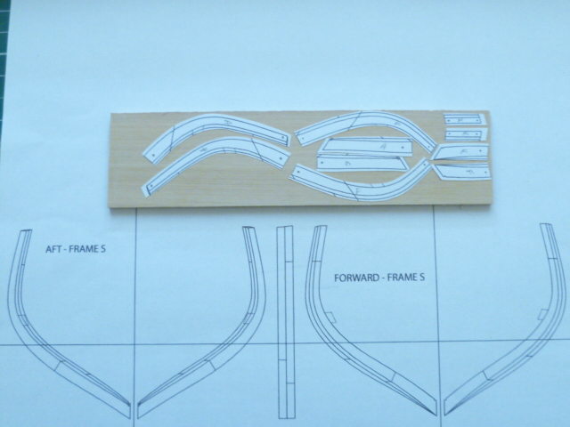
Hi Carl Half frames are cut from multiple pieces...there's a fore and aft side both sides made from 1\8 inchstock giving a frame thickness of 12 inchs full size. Once fore and aft side are glued the respective bevels are worked in and then the frame bolts are simulatedwith copper wire. The main sqaure frames are made exactly the same way except that now there's a floor timber and rebate for the keel to contend with. I try and avoid going to the docs....they keep finding reasons to send me away and slice me up!!!! Been falling apart ever since I reached 40!!!! Cheers....mick
- 504 replies
-
- 4
-
-
- washington
- galley
- (and 1 more)
-
Hi druxey Thanks for stopping by......I'm managing one frame a day at the moment. No rush.....should keep me out of trouble for a while! Cheers....mick
- 504 replies
-
- 3
-
-
- washington
- galley
- (and 1 more)
-
Hi Chuck The counter fashion piece's? Yep I had a trial run at those to try and work out a method......must have got the wrong end of the stick with which bit you were interested in...oops! Ideally those pieces need to be cut from a single piece approx 1 1\2 inchs wide by 4 inchs long by 1\2 inch thick.....with the test piece I laminated two1\4 inch pieces together. The first profile I shaped was the stern view. I then superimposed the longitudinal plan on top of the previously shaped piece....trying to ensure the bottom and knuckle line corresponded with the previous piece. I did post some pictures in the previous post......if you would like I can rearrange those into a seperate post....pictures tend to be clearer than a thousand words.....these were only practise pieces and may not be good enough to include on the model....I need to get the stern framing up first and test fit them. Hope this helps. Cheers...mick
- 504 replies
-
- 4
-
-
- washington
- galley
- (and 1 more)
-
Hi Kurt Glad to be of any help.....good luck with your build Cheers....mick
- 504 replies
-
- 2
-
-
- washington
- galley
- (and 1 more)
-
hi ken and christian thanks for looking in.........happy with the first frame to go in.....the aft cant frame may need some more work,need to study the plans a bit more! looking forward to more frames and a ship slowly emerging! cheers....mick
- 504 replies
-
- 3
-
-
- washington
- galley
- (and 1 more)
-
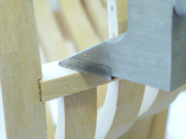
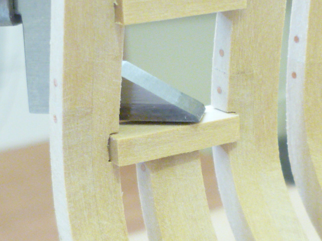
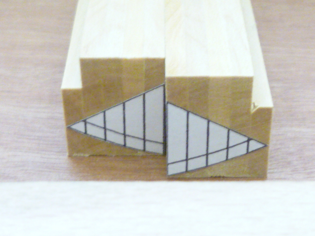
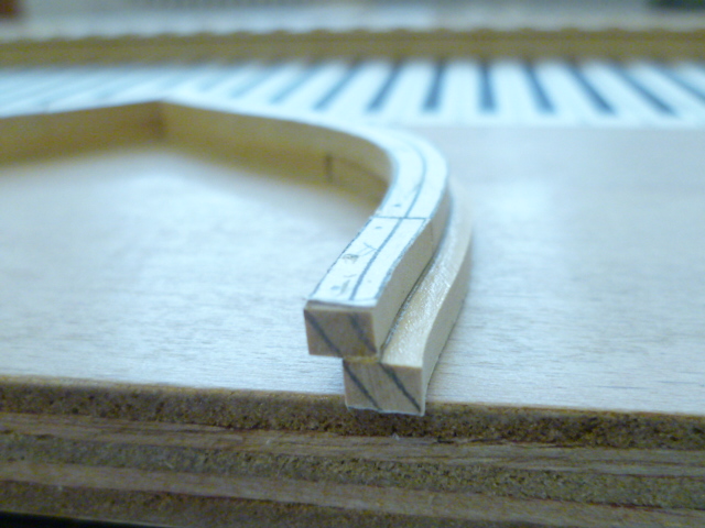
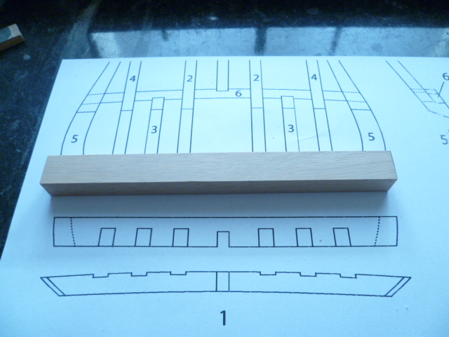
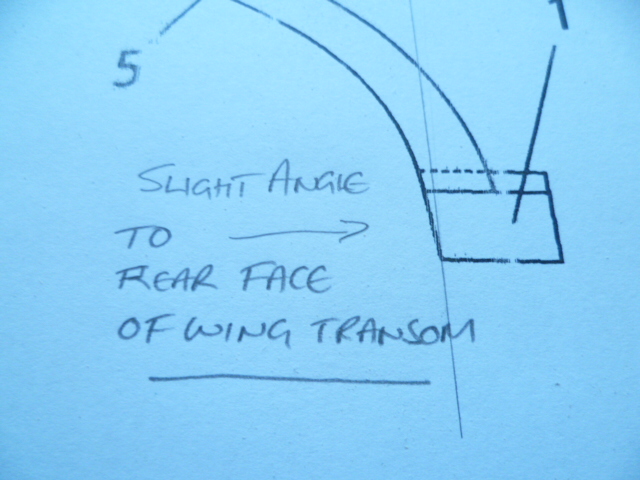
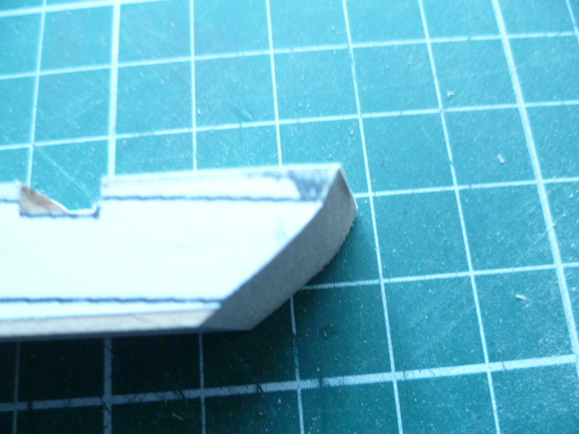
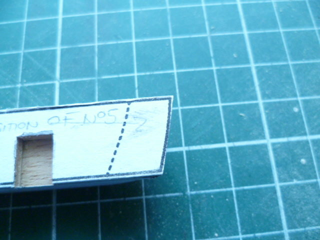
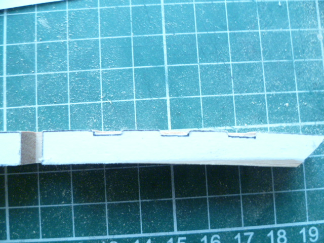
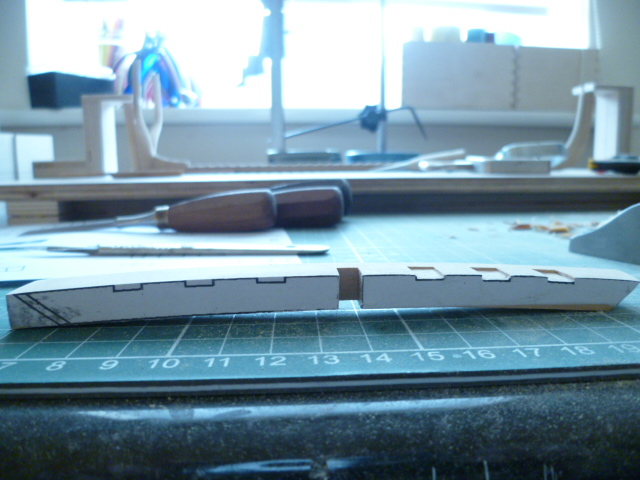
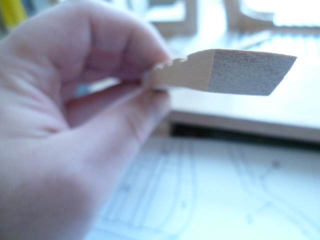
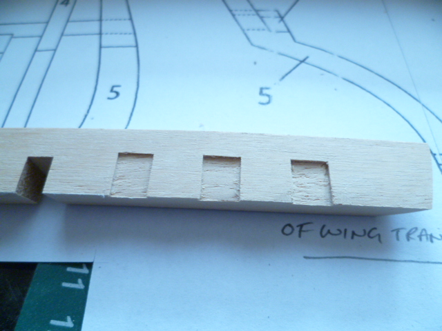
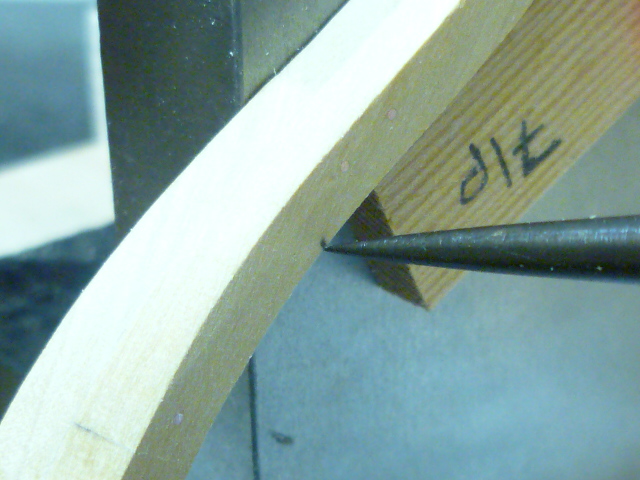
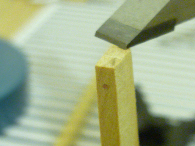
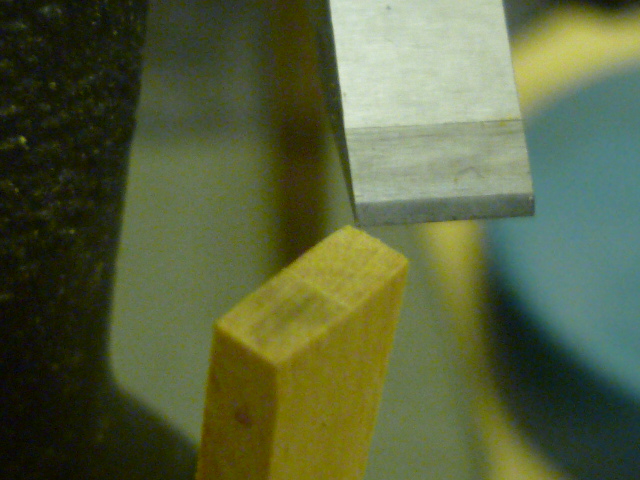
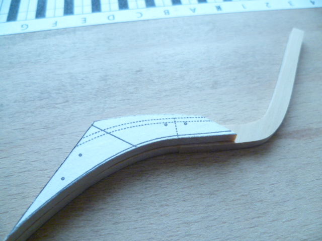
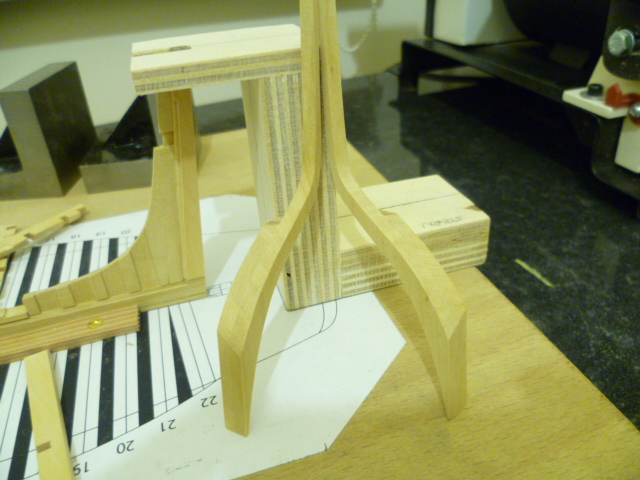
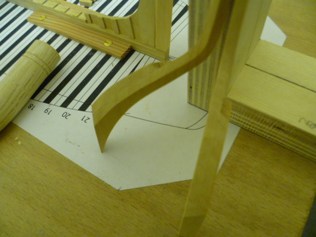
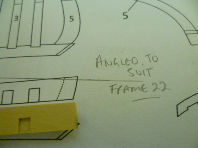
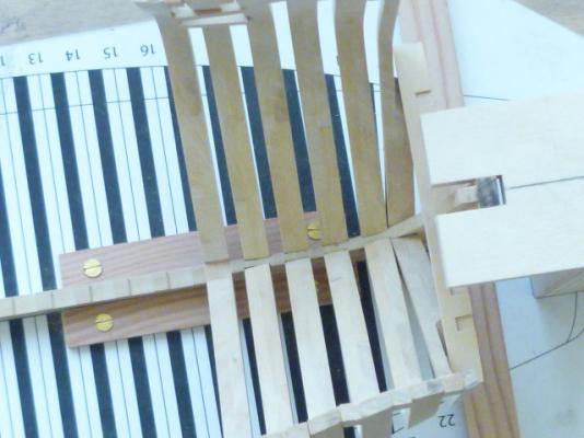
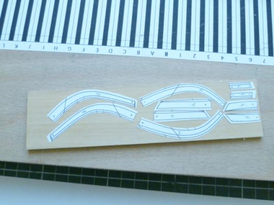
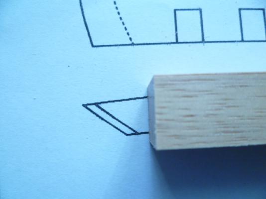
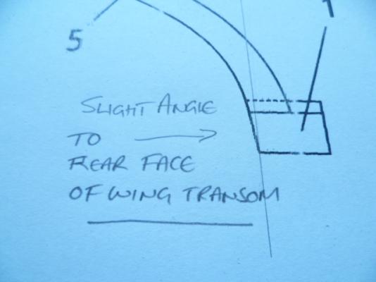
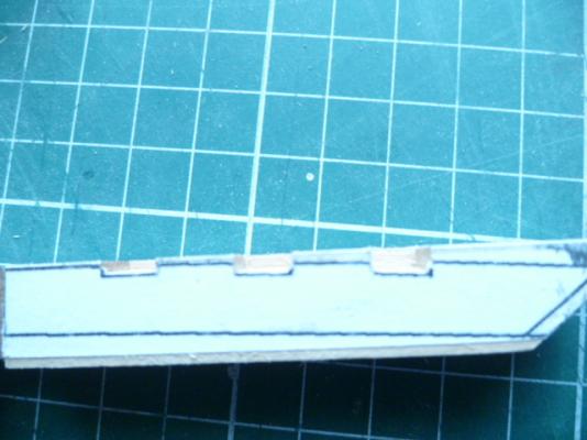
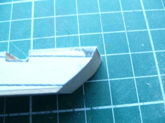
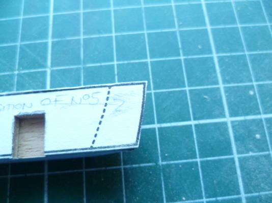
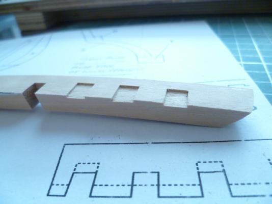
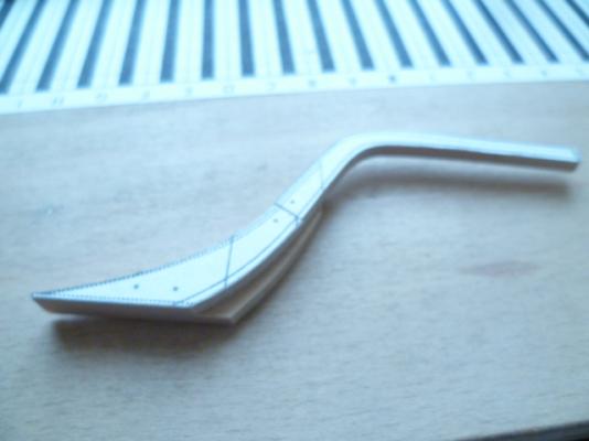
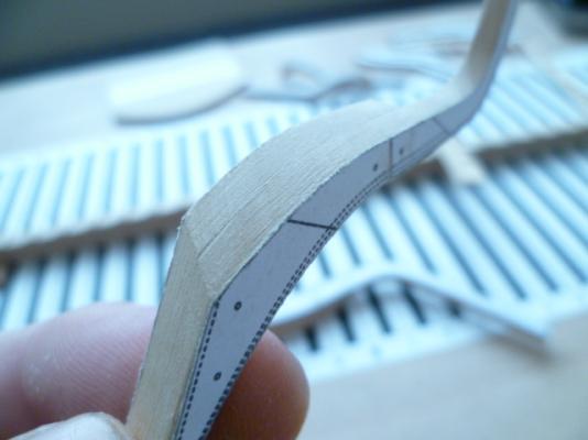
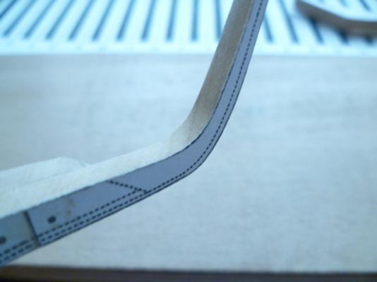
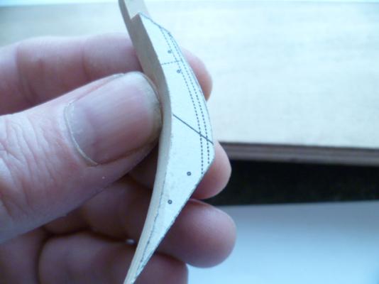
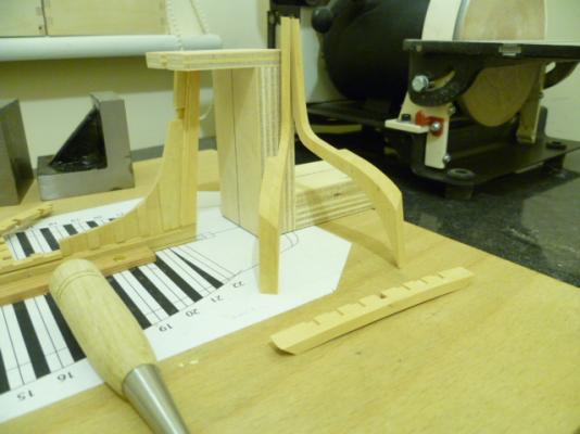
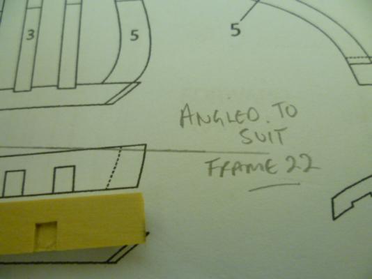
hi chuck i had to look twice myself at the wing transoms.....and the rest of em!!! the wing transom starts off as a sqaure block of timber,slightly thicker than is required but wide enough to paste the plan view on top. i had a play around this morning and remade the piece in 1/24 scale,primarily because its easier to photograph and secondly it shows the round up better. i havnt gone to any great lengths to finish the piece,made from a bit of ramin i had lying around,but the photographs should show the construction sequence in the order i did it. the rear face of the wing transom need to have its face angled in order to be in the same plane as the rabbet of the stern post......not shown on the plans. the ends of the transoms may need to have an angle planed on them in order to fit flush against the rear face of frame 22.......the bottom of the wing transom will fit against the top of the rear part of frame 22. hope this makes sense. the following photos should be in the right order for the construction sequence.


- 504 replies
-
- 11
-
-
- washington
- galley
- (and 1 more)
-
Hi Patrick It's nice to see a ship slowly emerge.....only another 40 frames to go! Cheers....mick
- 504 replies
-
- 4
-
-
- washington
- galley
- (and 1 more)
-
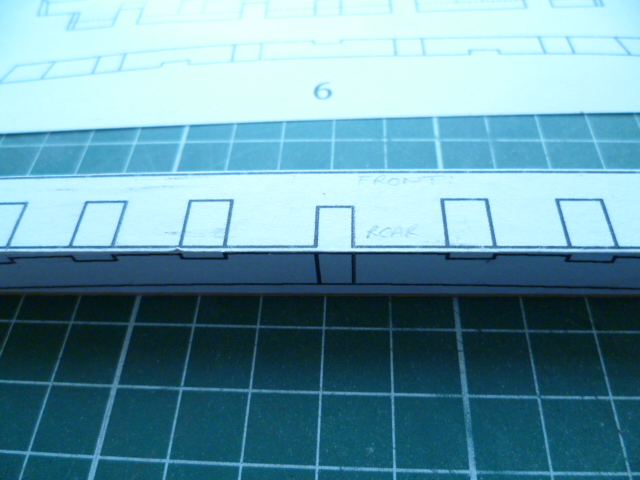
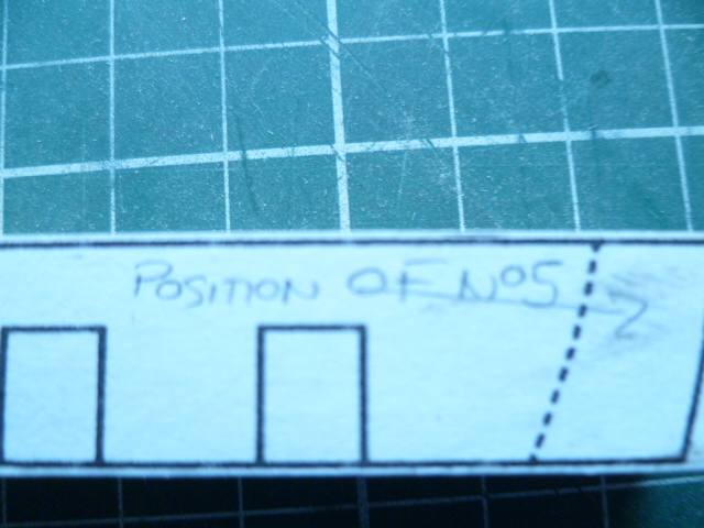
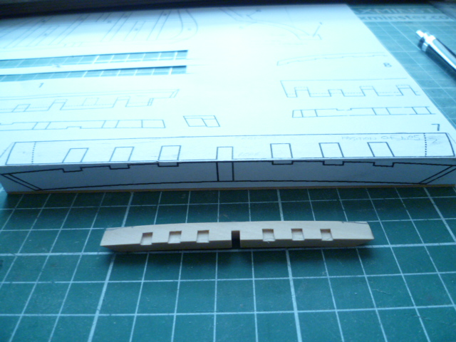
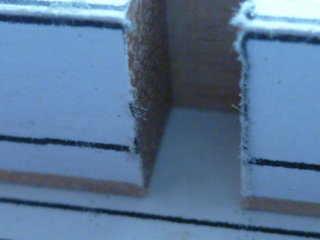
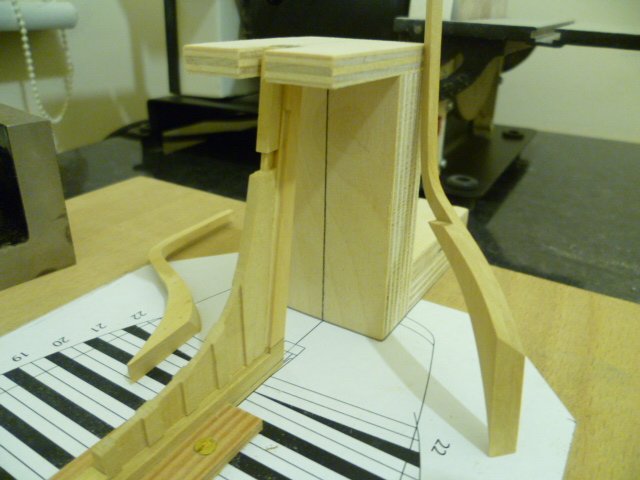
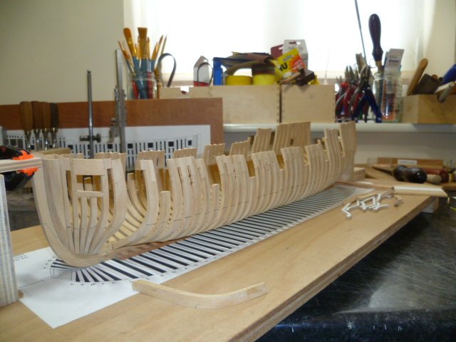
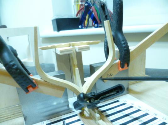
WASHINGTON GALLEY PART 6........FIRST FRAME IS RAISED!!!! HI ALL HAVING MADE THE LAST HALF FRAME AFT I DECIDED IT WAS PERHAPS WISE TO RAISE THIS FRAME FIRST THE SINGLE AFT CANT FRAMES LEADING EDGE BUTTS UP AGAINST THE REAR FACE OF THIS FRAME SO IT MAKES SENSE. I CAN THE WORK TOWARDS MIDSHIPS WITH THE REST OF THE AFT HALF FRAMES. I MAY THEN SWITCH MY ATTENTION TO THE FORWARD CANT AND HALF FRAMES AND THE DREADED HAWSE PIECES. MIDSHIPS FRAMES ARE FROM ( 6 FRAMES FORWARD OF DEADFLAT AND 6 FRAMES AFT OF DEADFLAT) ALL THE SAME BASIC SHAPE WITH NO BEVEL. THE HEIGHTS ARE SLIGHTLY DIFFERENT,TO ACCOUNT FOR THE SHEER,AND SOME HAVE RECESSES FOR THE GUNPORT SILLS AND SWEEP PORTS.......BATCH PRODUCTION TIME! SO THATS WHERE I AM AT THE MOMENT.....TIME FOR A CELEBRATORY SNIFTER PHOTOS OF THE FRAME RAISING FOR YOUR DELICTATION CHEERS........MICK


- 504 replies
-
- 13
-
-
- washington
- galley
- (and 1 more)
-
Hi ian Beautiful work sir! Nice job on the milling cutter as well. Work shop heaven sell some lovely boxwood,single pieces or a bag full if you ever need any more. Cheers....mick
-
Hi Johann Stupendous work as always.....I finally found a new superlative.... A Tue master craftsman at work!! I look forward to more. Cheers...mick
-
Hi Carl Lol!!!! Despite wearing glasses for reading I was still having trouble seeingall those converging lines! And for a measly £10 they are a godsend. Tight joints help.....less glue to fill the gap! The touch is less sensitive today as I ran a lovely sharp liogier needle rasp over my index finger!....no damage done but time for a coffee...as a small aside I made frame 22 today....the last half frame...the previously made aft cant frame butts up against this one at a slight angle.....we will see how accurate I have been when it comes time to commit to glue a bit later today! Still a journey man mate....when I get to the level of ed tosti,Dan vadas,Johann,Alexandria,j k Lee to name but a few then I think master might be a worthy title.....till then I am a paduwan.....grasshopper etc!!!!!! Cheers......mick
- 504 replies
-
- 5
-
-
- washington
- galley
- (and 1 more)
-
Hi Ken Thanks for looking in. Those cant frames are proving a nice little challenge.....and the optivisors are a godsend especially with all those lines converging so closely together! Cheers....mick
- 504 replies
-
- 3
-
-
- washington
- galley
- (and 1 more)
-
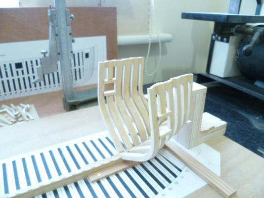
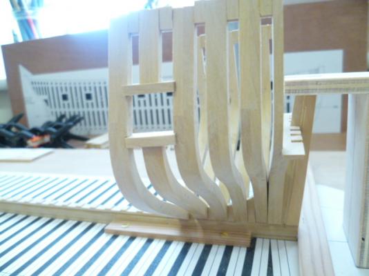
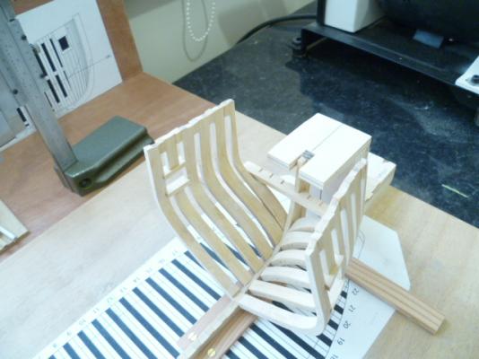
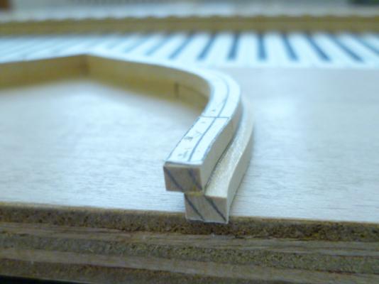
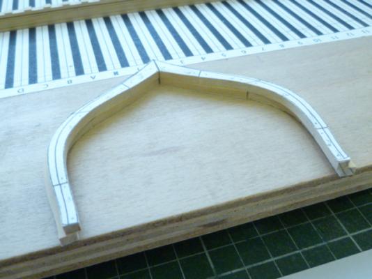
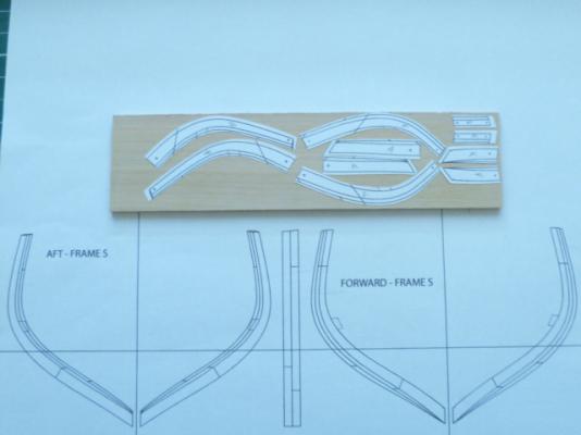
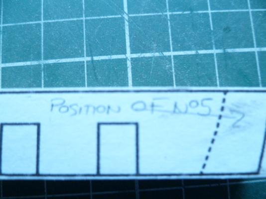
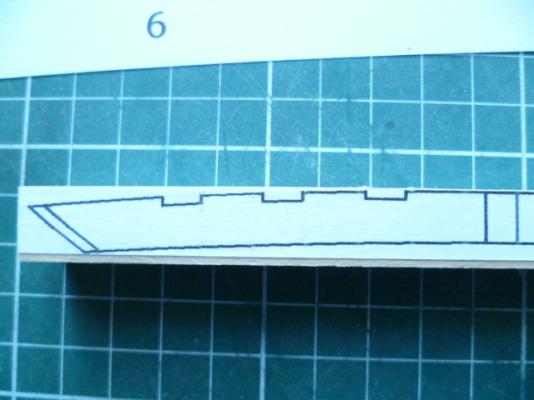
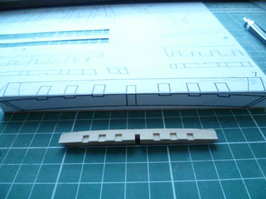
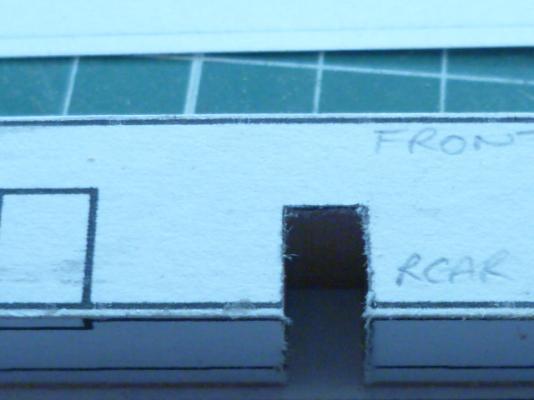
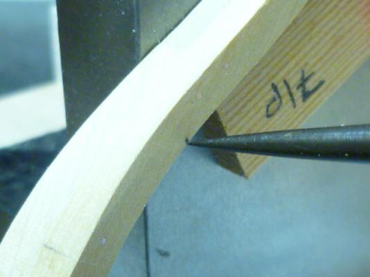
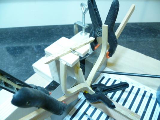
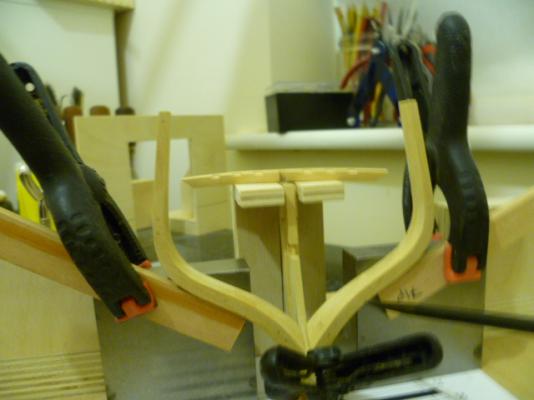
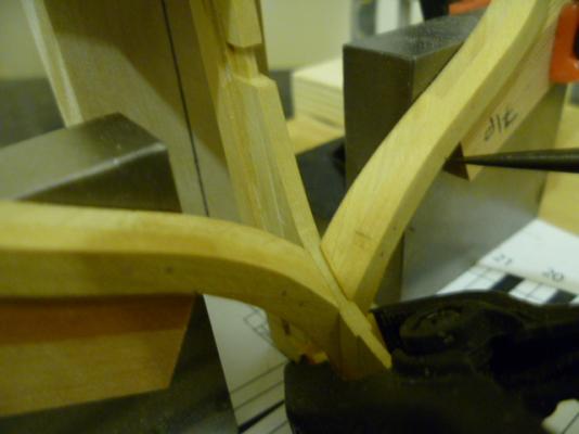
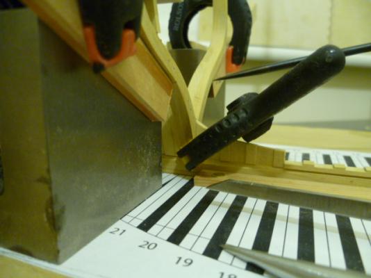
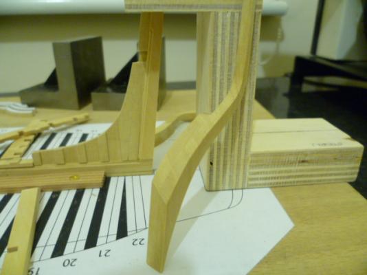
WASHINGTON GALLEY PART 5 HI ALL TODAYS EFFORTS WERE MAINLY CONCERNED WITH THE PRODUCTION OF THE AFT CANT FRAME (N0 22). ALL PARTS WERE CUT OUT TO THEIR RESPECTIVE LINES AS INDICATED ON THE PLANS,CAREFULLY GLUED UP,AND THEN THE RESPECTIVE BEVELS CUT. ATTACHED PHOTOS SHOW THE RESULTS. IT WOULD APPEAR THAT THE LOWER WING TRANSOM NEEDS TO HAVE ITS ENDS ANGLED SLIGHTLY IN ORDER TO FIT FULLY AGAINST THE REAR FACE OF THE CANT FRAME. CHEERS.....MICK THE OPTIVISORS ARE A RECENT AQUISITION.......I CAN NOW SEE WHAT IM DOING!!!!


- 504 replies
-
- 10
-
-
- washington
- galley
- (and 1 more)