


Brinkman
-
Posts
154 -
Joined
-
Last visited
Content Type
Profiles
Forums
Gallery
Events
Posts posted by Brinkman
-
-
Thank you Jim and every one else for the likes!
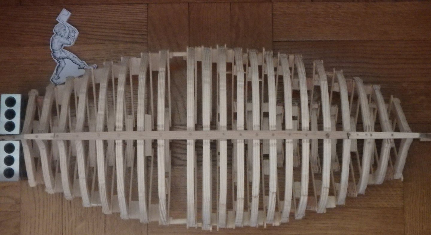
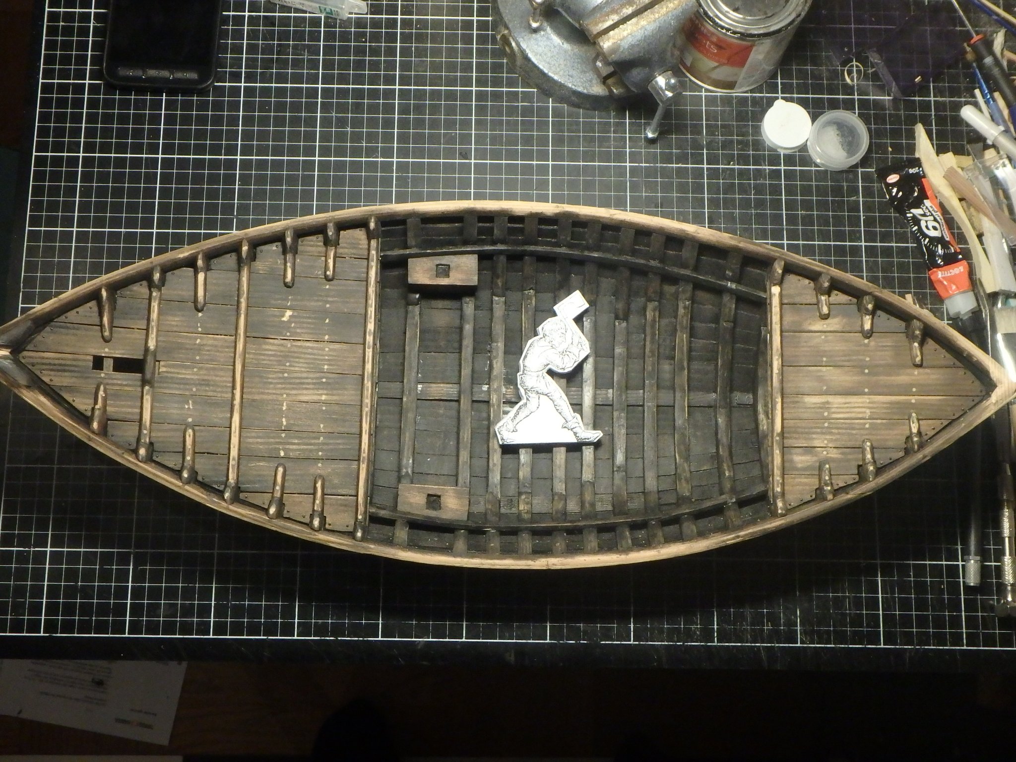
Next up was completing the decks.
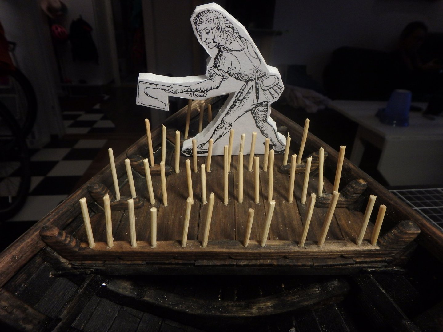
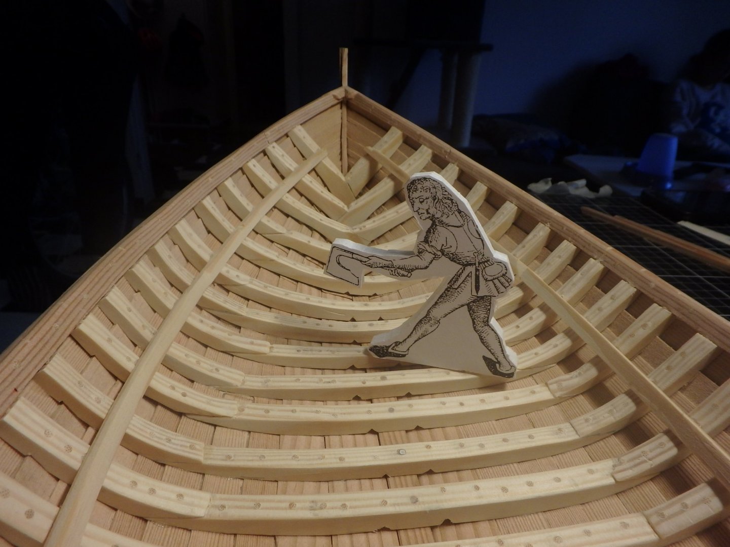
The worker hasn't learned his lesson and is yet again using the wrong kind of axe.
The shipswright deems the work tolerable, but that it needs another coat of paint after all the sanding.
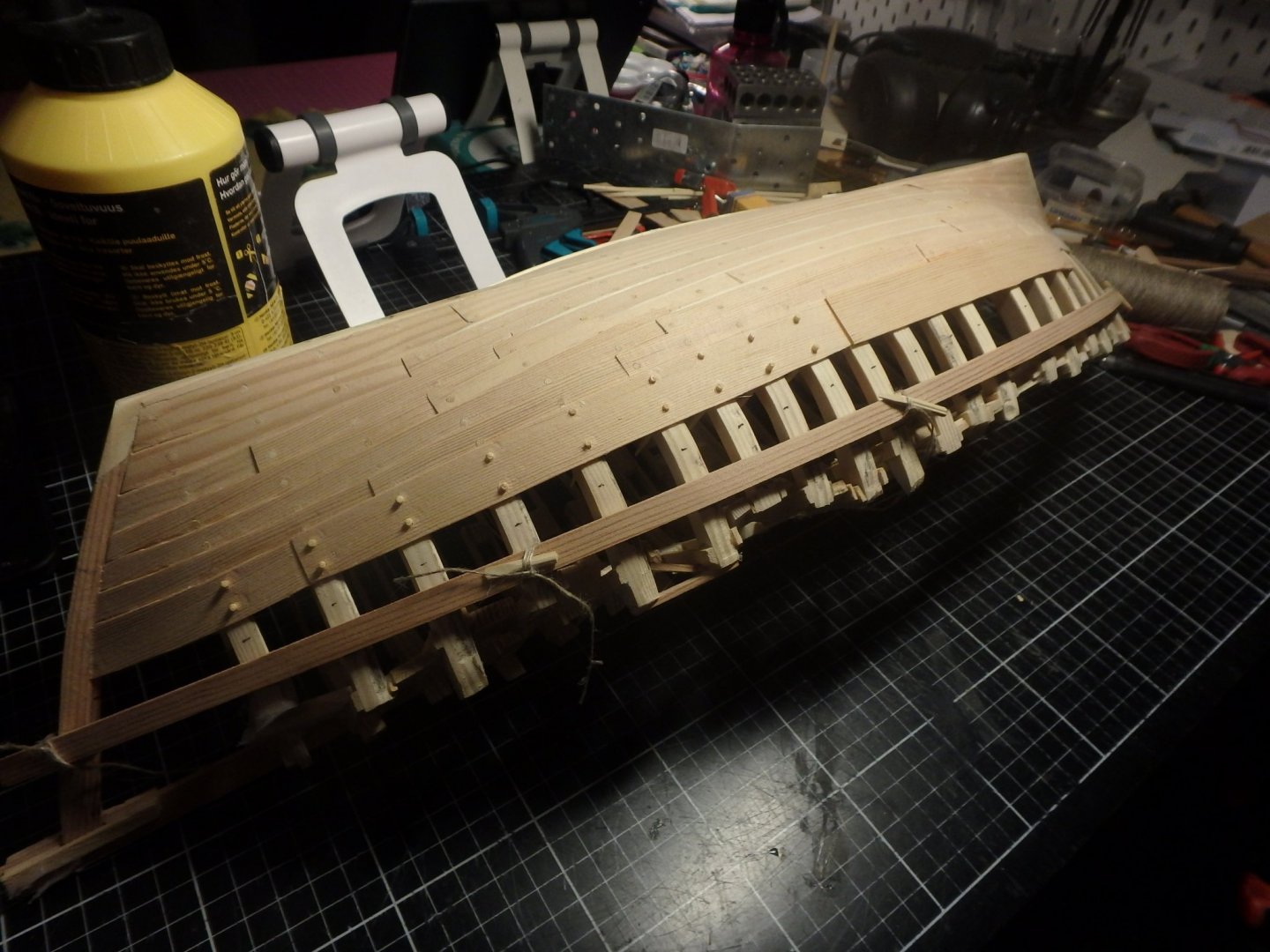
Planks and knees are fastened with treenails to the beams, but I run a line of nails to also fasten the planks to the hull.
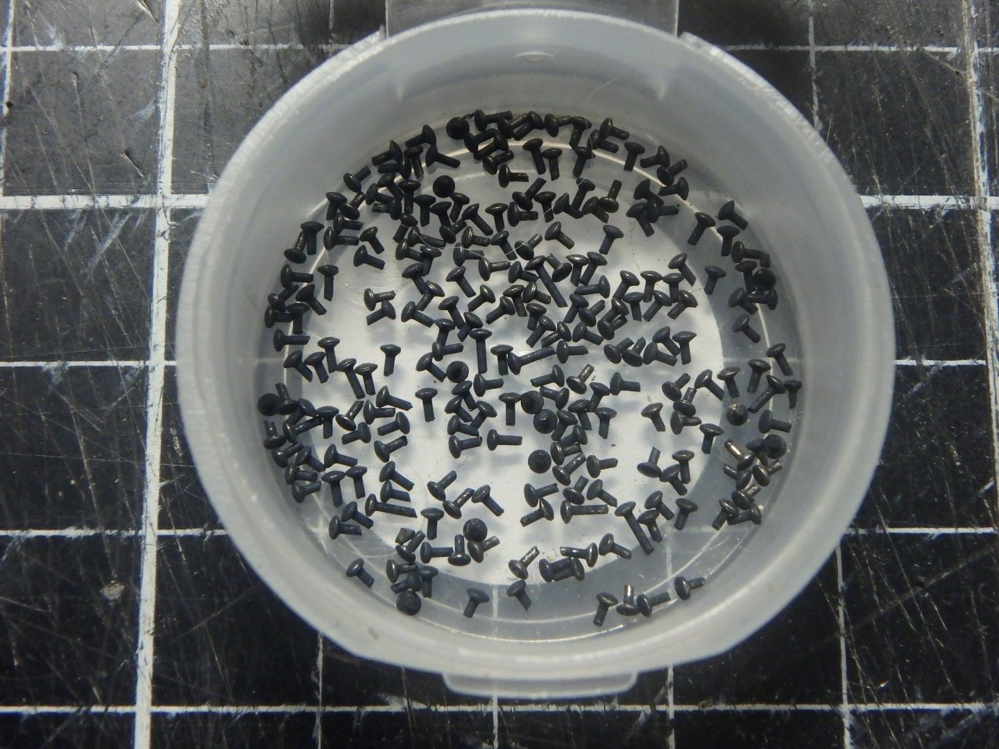
I bought the thinnest pins I found and use their 1.3mm (3/64") heads for nails after blackening them. Quite fiddly work.
I have also started nailing the hull, but will spare you the sight of it until it's all painted as I know that some of you are quite sensitive to too obvious nailing 😛
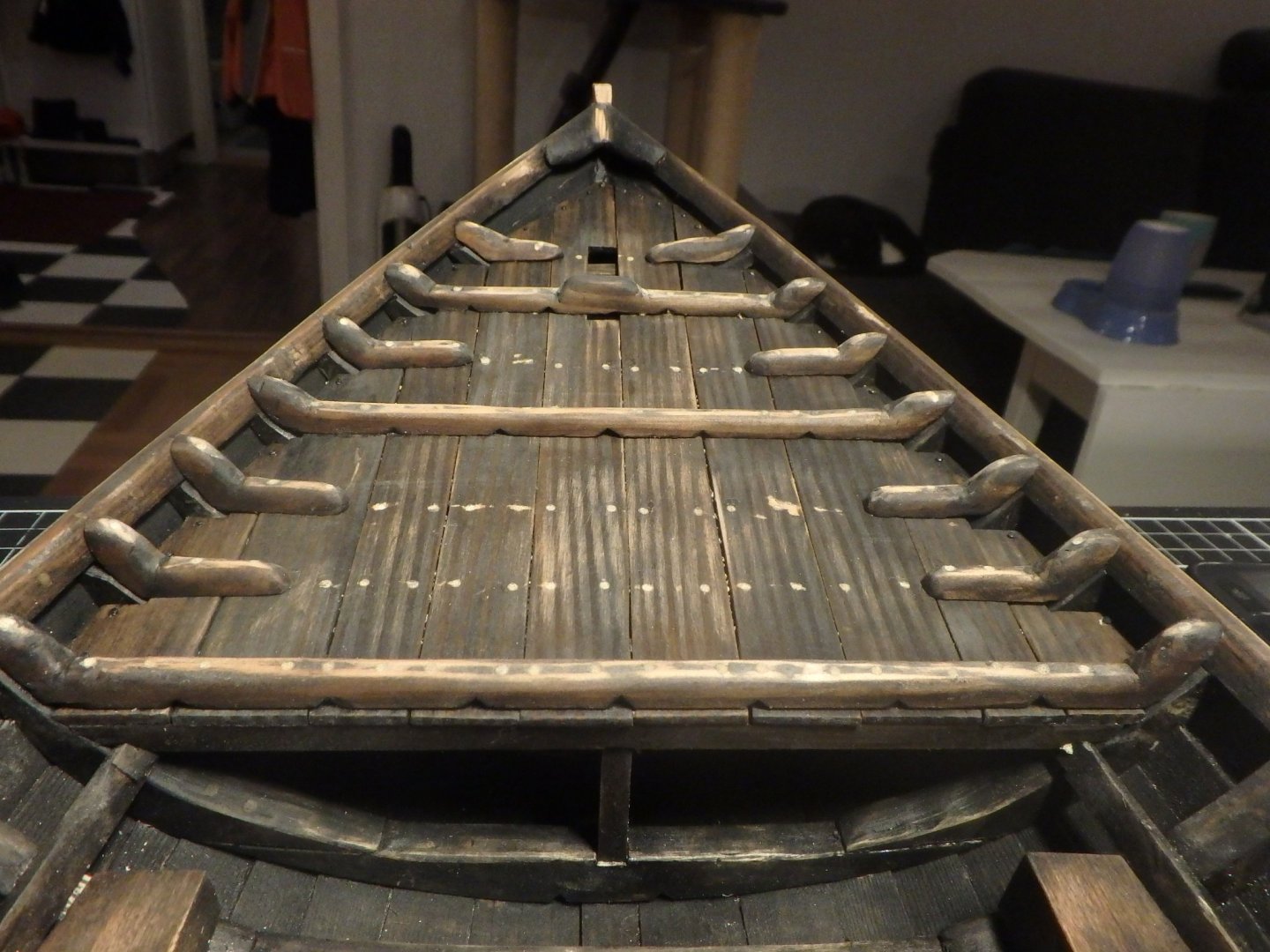
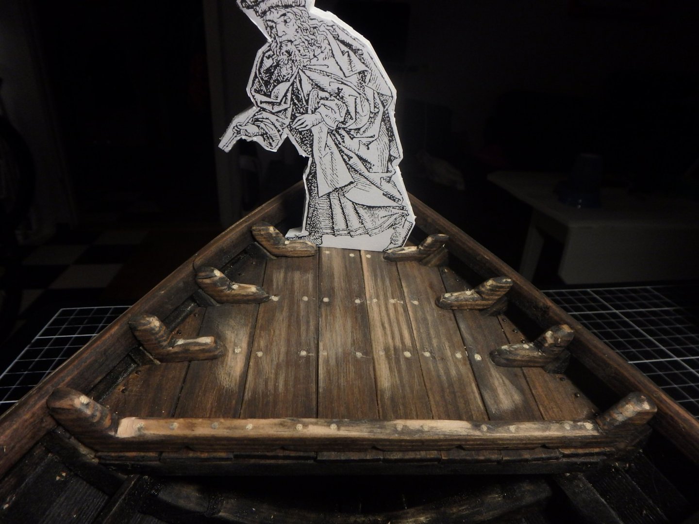
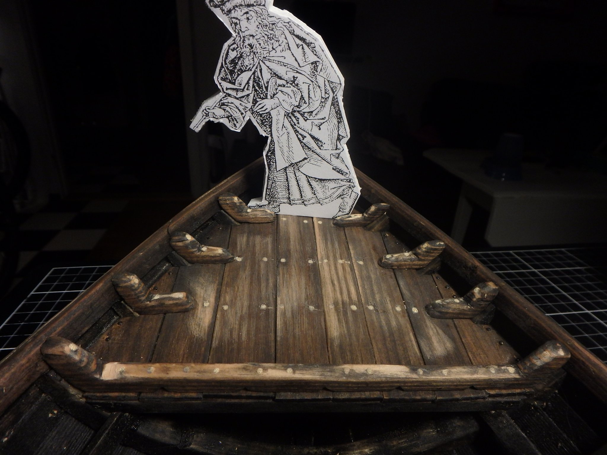
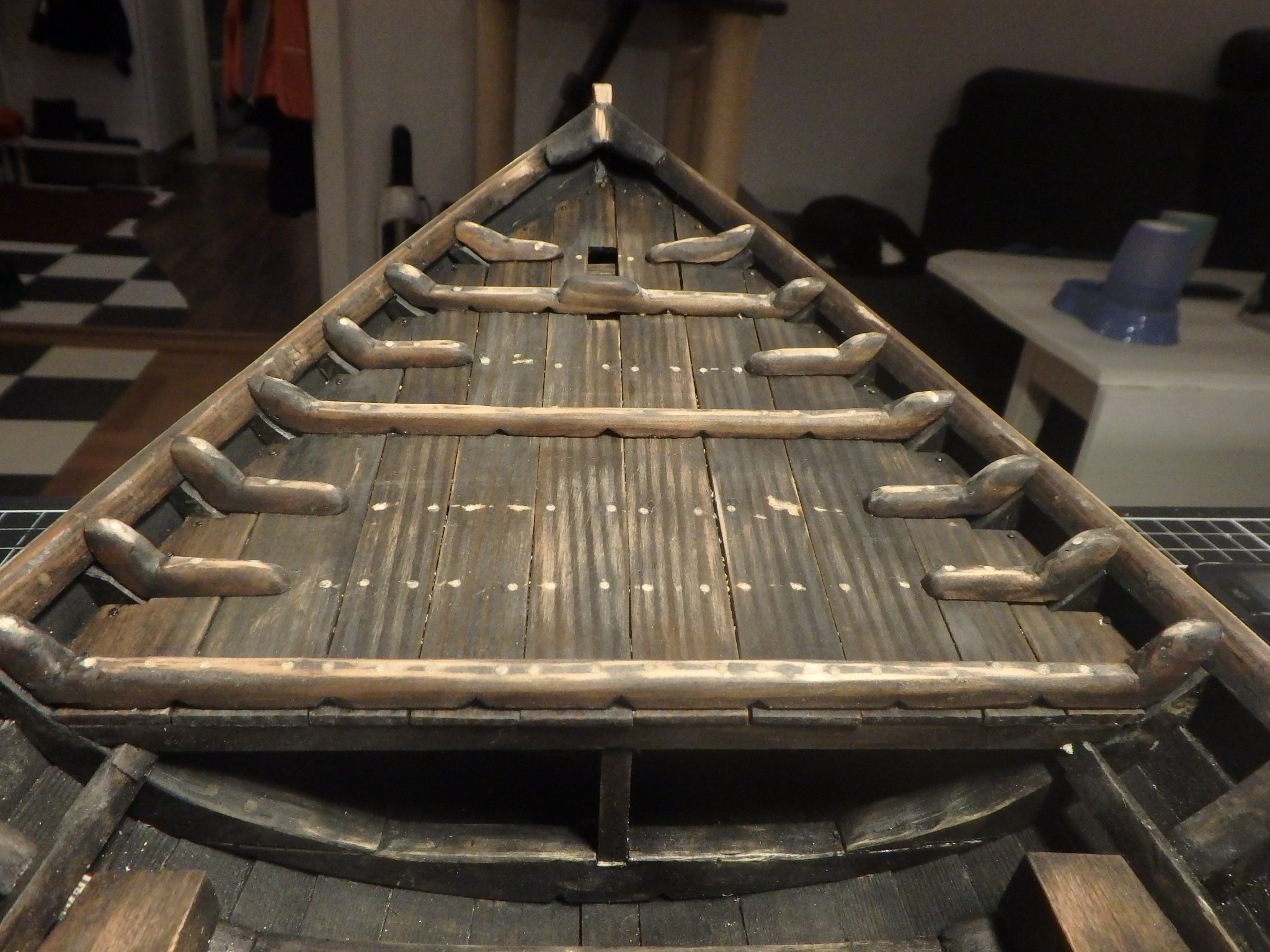
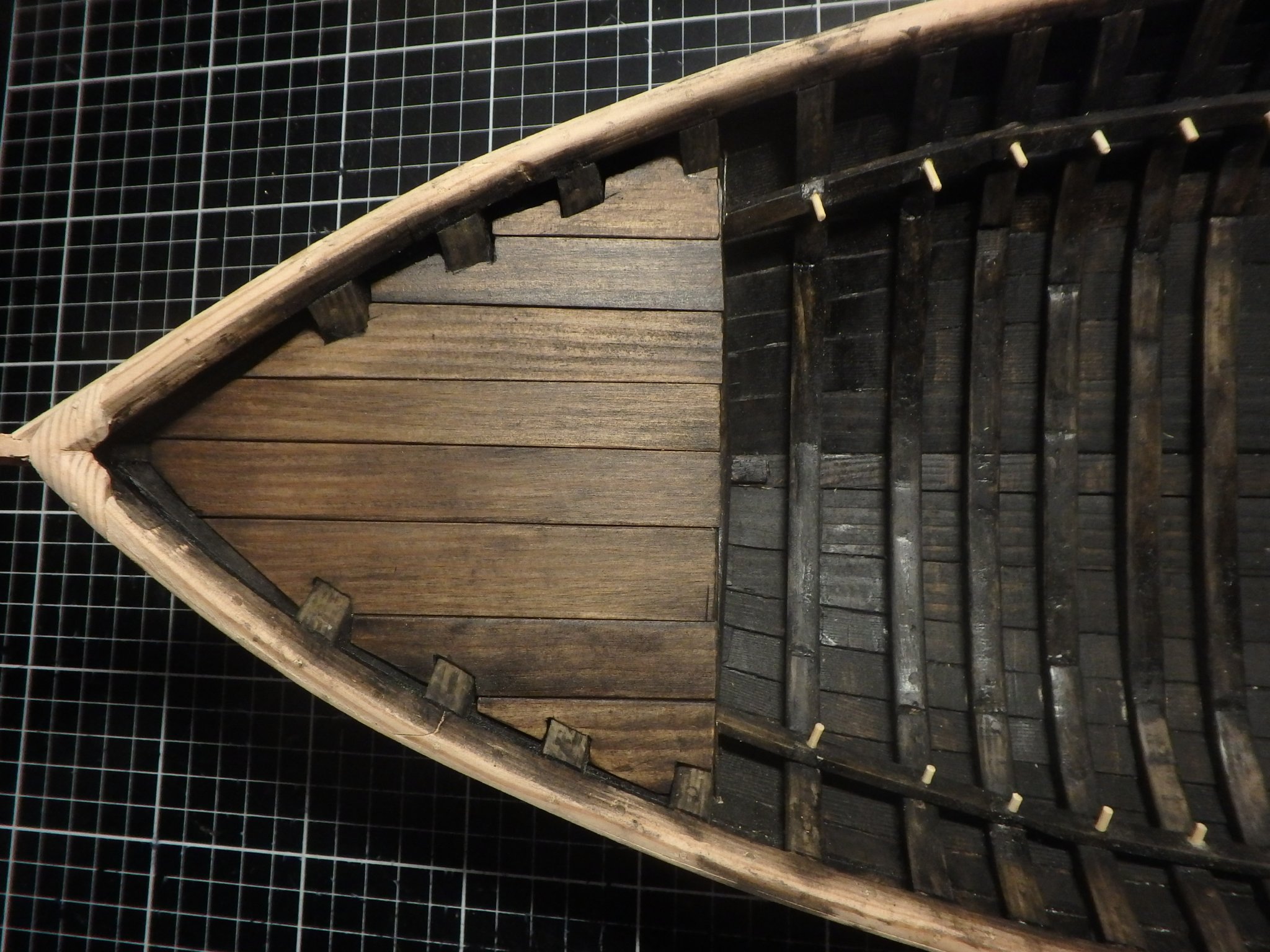
Fore deck also done. The opening in the front is of course for the bowsprit.

There almost isn't anything left of the decks in the wreck I base this build on, but I take inspiration from other similar wrecks from the region.
I alternate the standing knees with rider beams with knees in the ends to strengthen the decks. The fore deck also has a stanchion underneath.
The primary cargospace is of course aft of the mast and it will have ceiling and bulkheads but I think they also had cargo fore of the mast. But that area had not any ceiling on it and I think it would look weird to leave that area "naked", so I enlarged the fore deck and argue that one can load heavy stuff like barrels and bricks under it and lighter loads on top. The watercourses in the rider beams can be used for belaying. And the space underneath is of course also used for spareparts, tools and ballast.
An early thought of having a large fore deck was to have it act as shelter for the crew, but it proved too cramped. The ship is so small that it wasn't used for any longer travels any way.
Next up is to furnish the main cargospace and having gangplanks on the sides.
- GrandpaPhil, luponero, Moab and 2 others
-
 5
5
-
Thank you for the Steven for the encouragement!
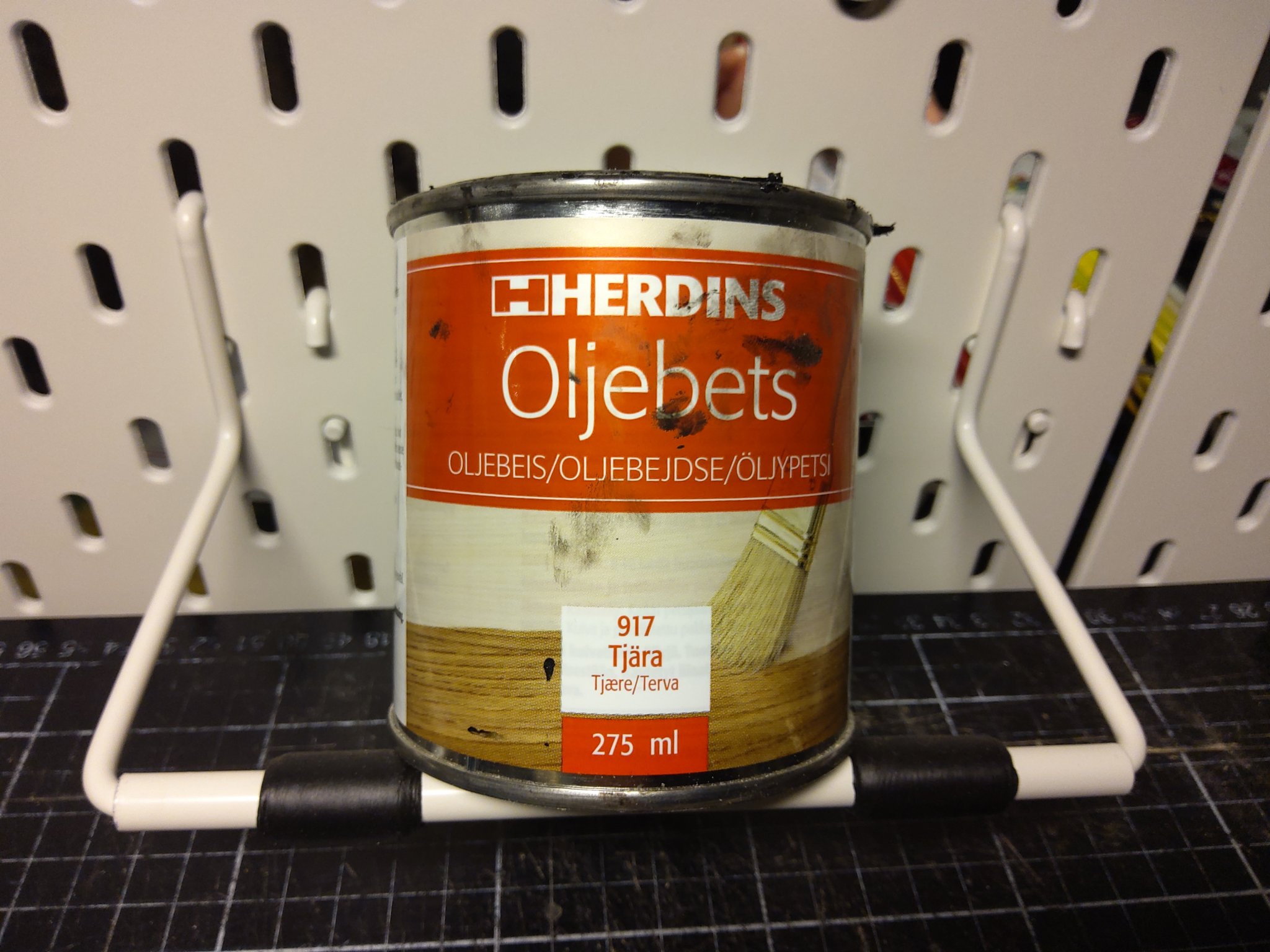
Binho, the paint is from a swedish brand and I think a correct description of the paint would be that it is an oilbased wash meant for furniture and the colour is appropriately called tar. It gets a nice finish if it dries for an hour and the exposed areas is then wiped off to get contrast. But today I got some spots where it turned shiny and I must tone it down.

(The can has the description in both swedish, norwegian, danish and finnish)
-
-
Thank you Moab and Binho! And thank you Steven for the link, it's always good to find more original parts to look at.
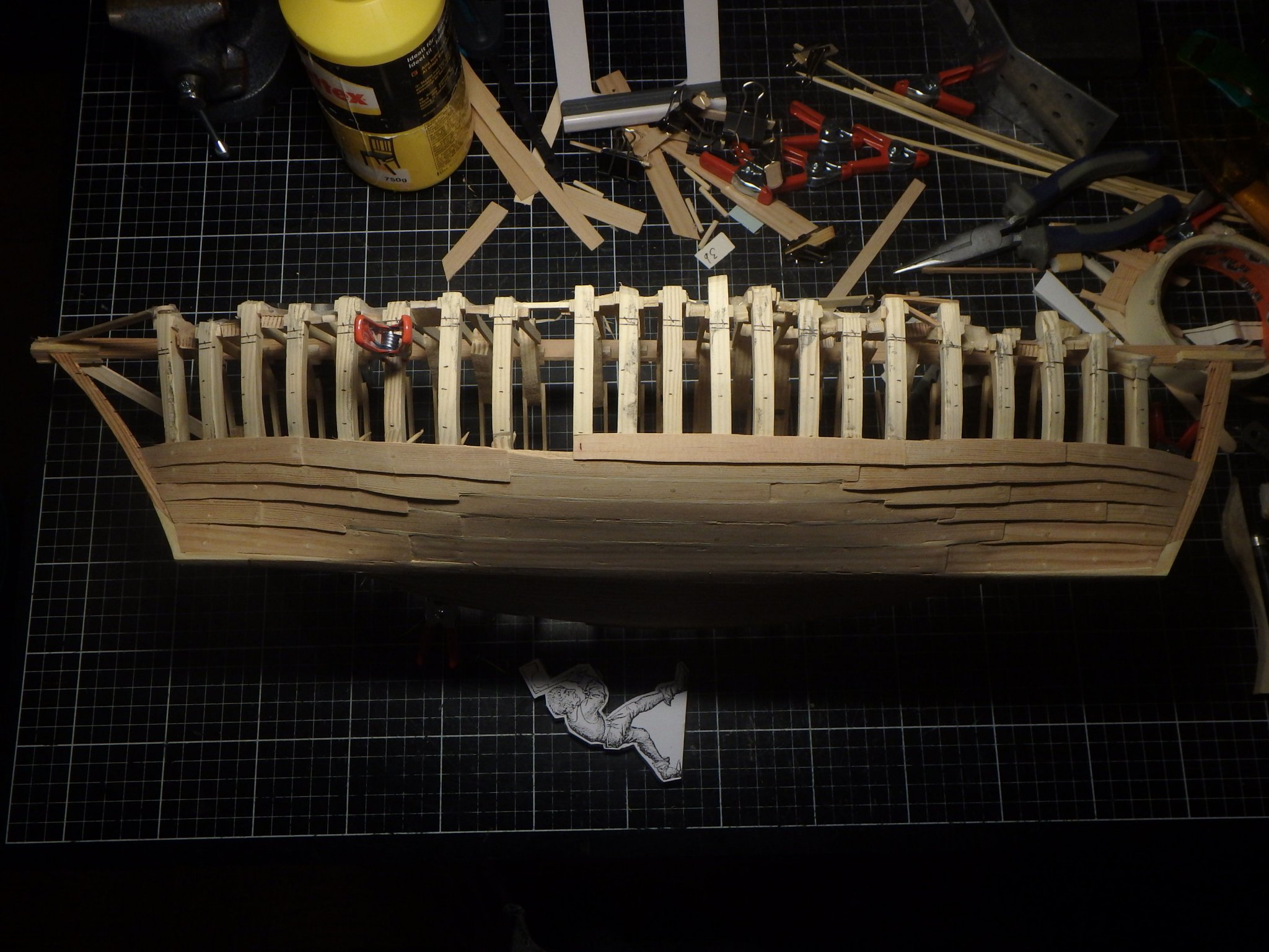
There was a lot of filing to do to smooth out the inside. And than the shelf was installed.
The stern deck was next and I planked it what I thought was the easiest (and therefore most likely) way.
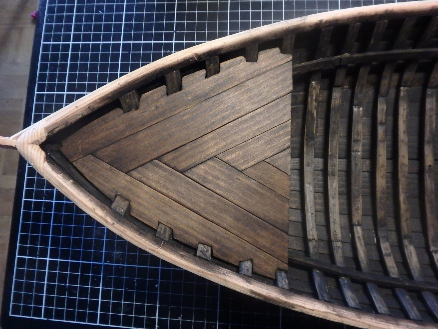
But the next day I undestood how wrong my thought process must have been and I redid it more according to finds. Much better this way. Standing knees, treenails and iron nails will be added later.

(The deck is also smaller now. I saw that I needed more space towards a future bulkhead and was therefore actually glad that I had to rip out the deck)
I'm giving everything a quick coat of paint as I build to reach all nooks and crannies and will go over it again later for finishing. The paint is an oilbased wash and I havn't used it before but like how slowly it dries and how it is absorbed in the wood.
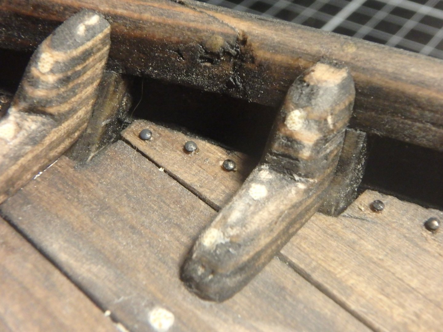
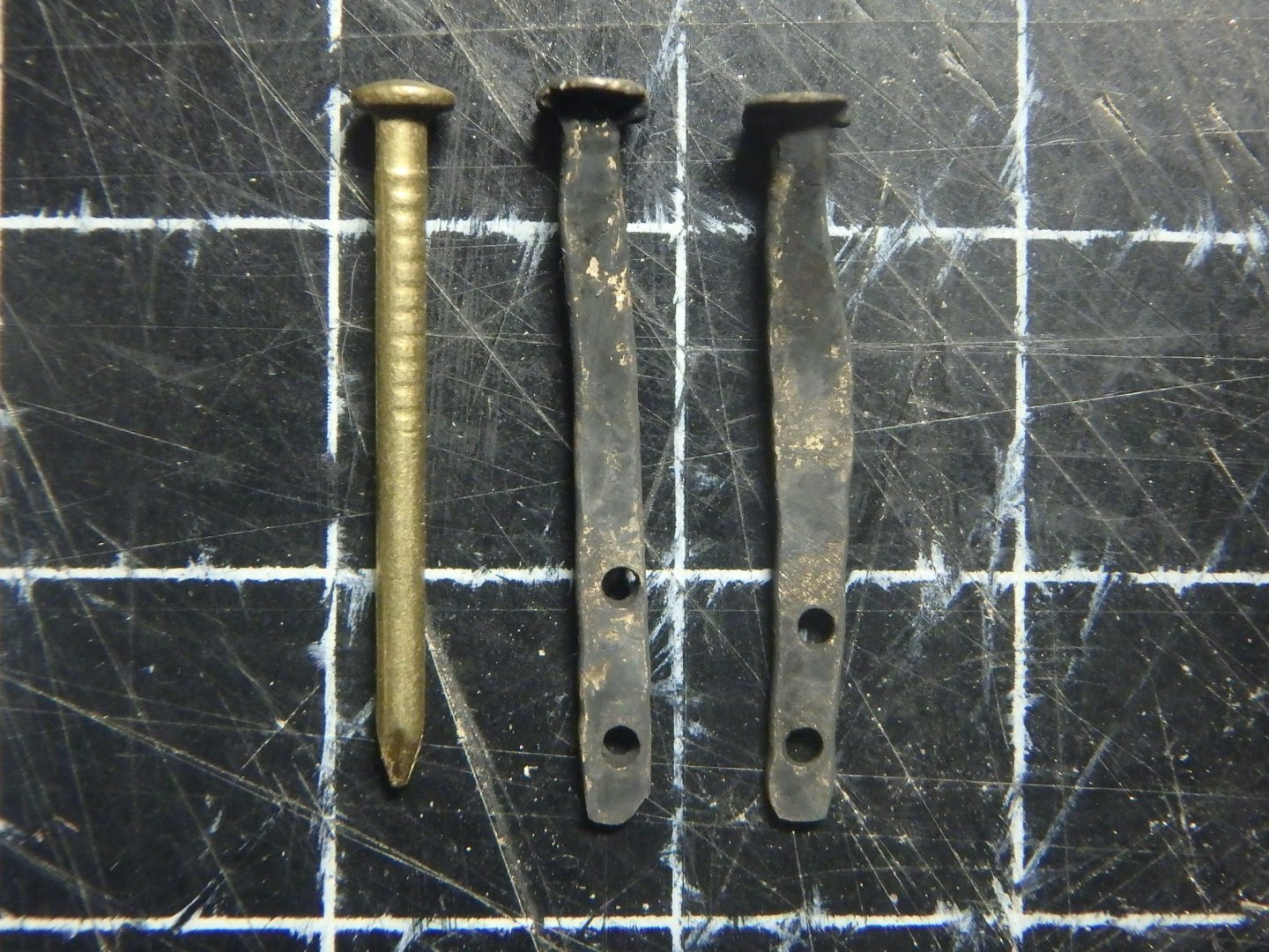
Large cogs had the beams hook into the planking, but smaller cogs instead had large iron bolts doing it. This was not to keep the beams in place, but to keep the hull in place and keep it from bulging out.
I did these rosebolts by flattening brass nails and using blackening fluid.
Next up is the forward deck.
- mtaylor, bigpetr, Chuck Seiler and 4 others
-
7
-
It's impressive how many pictures you find Steven, thanks! I think I'll go with the hole under the clamp, that looks both like the most sturdy and accurate one. Nice detail on the pic from Luttrell's showing how I can fix the standing rigging.
- Louie da fly and mtaylor
-
2
-
Thank you a lot for your encouragement Steven! It's good that you brought up the subject of cleats as I'm pondering it myself. I only see two variants:
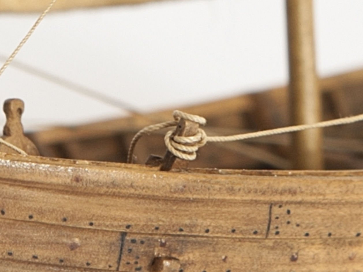
(Source https://digitaltmuseum.se/021025899838/fartygsmodell)
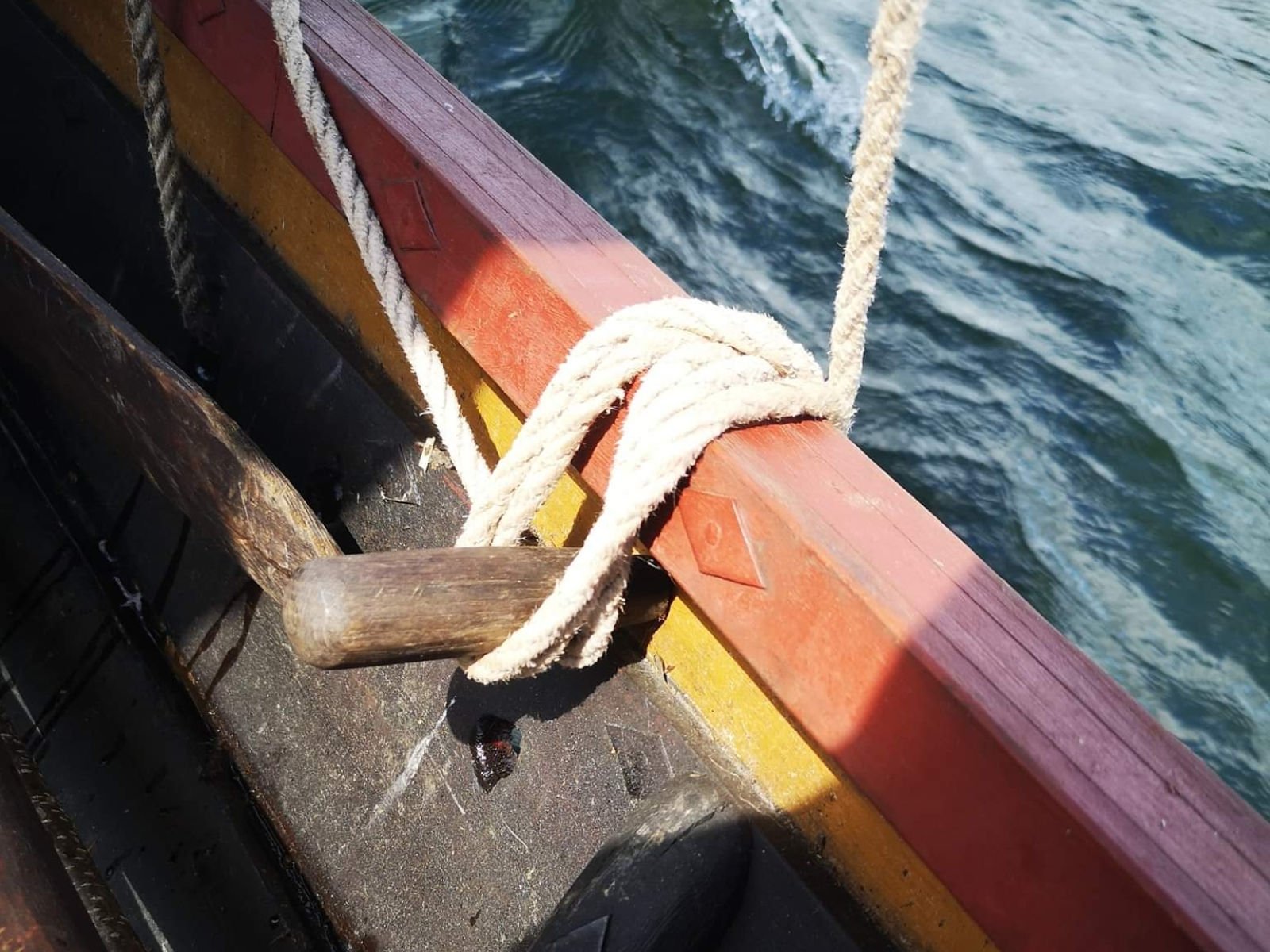
Having the frame extend above the clamp and tie the rigging to it.
Or

(Source: Exploring the medieval farmer on facebook)
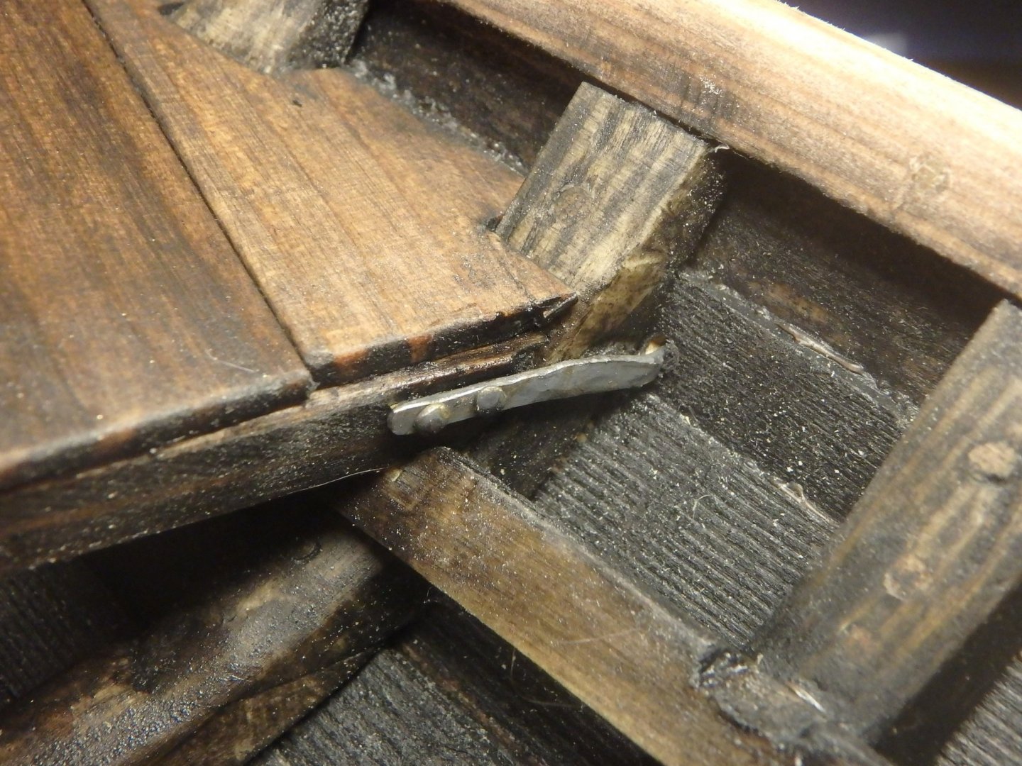
Having holes under the clamp. This picture is of an earlier viking boat, but as my clamp is cut off under the clamp like this

I think the second one would be best? Do you have any suggestion? I see some mediveal models with modern looking cleats, but surely that is not accurate?
Edit: Perhaps the first version is feasible anyway as I will have standing kness on the decks and they could extend upwards and act as cleats?
- GrandpaPhil, mtaylor, Moab and 1 other
-
4
-
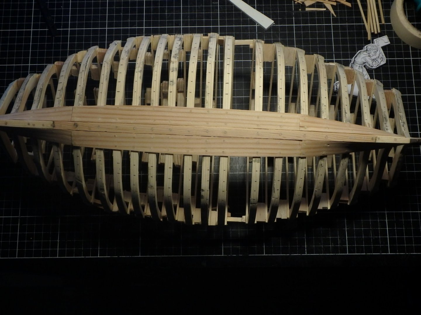
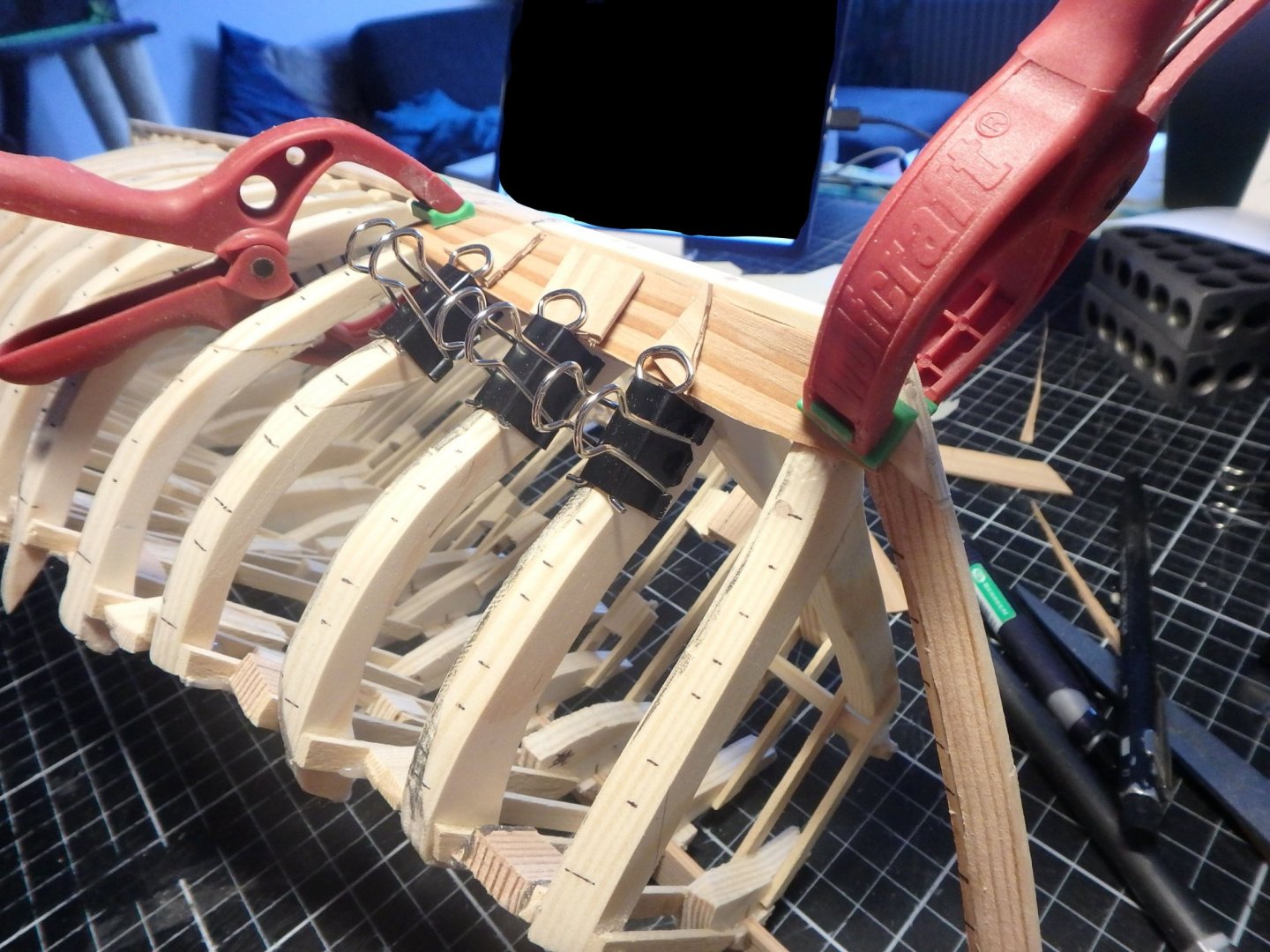
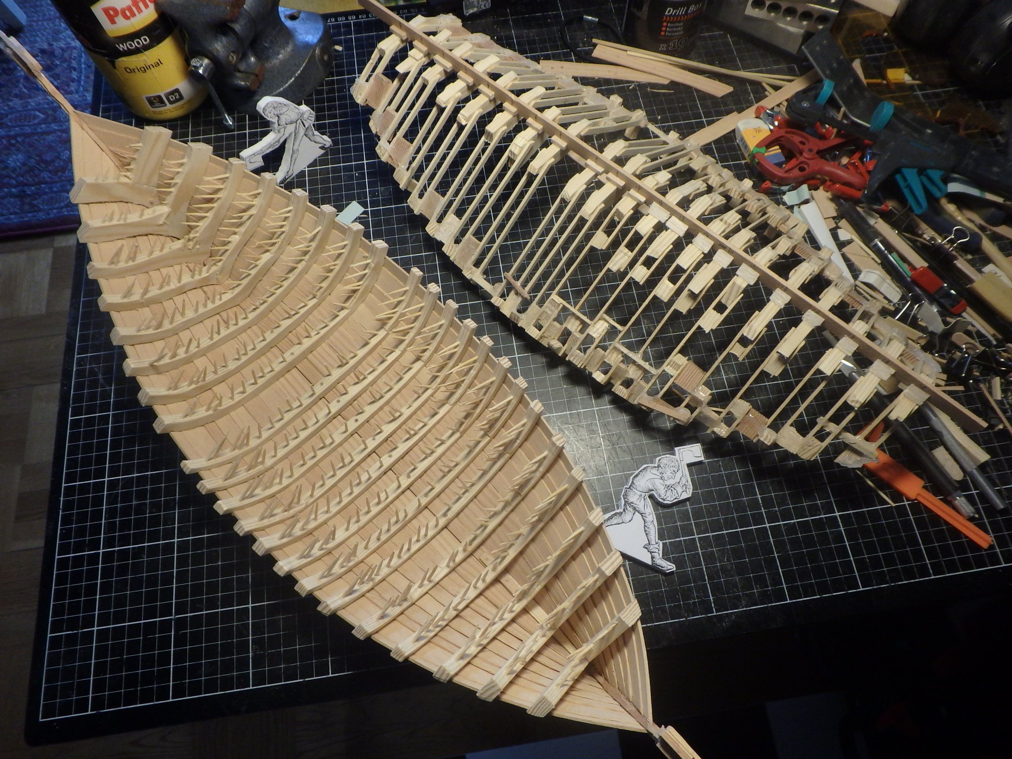
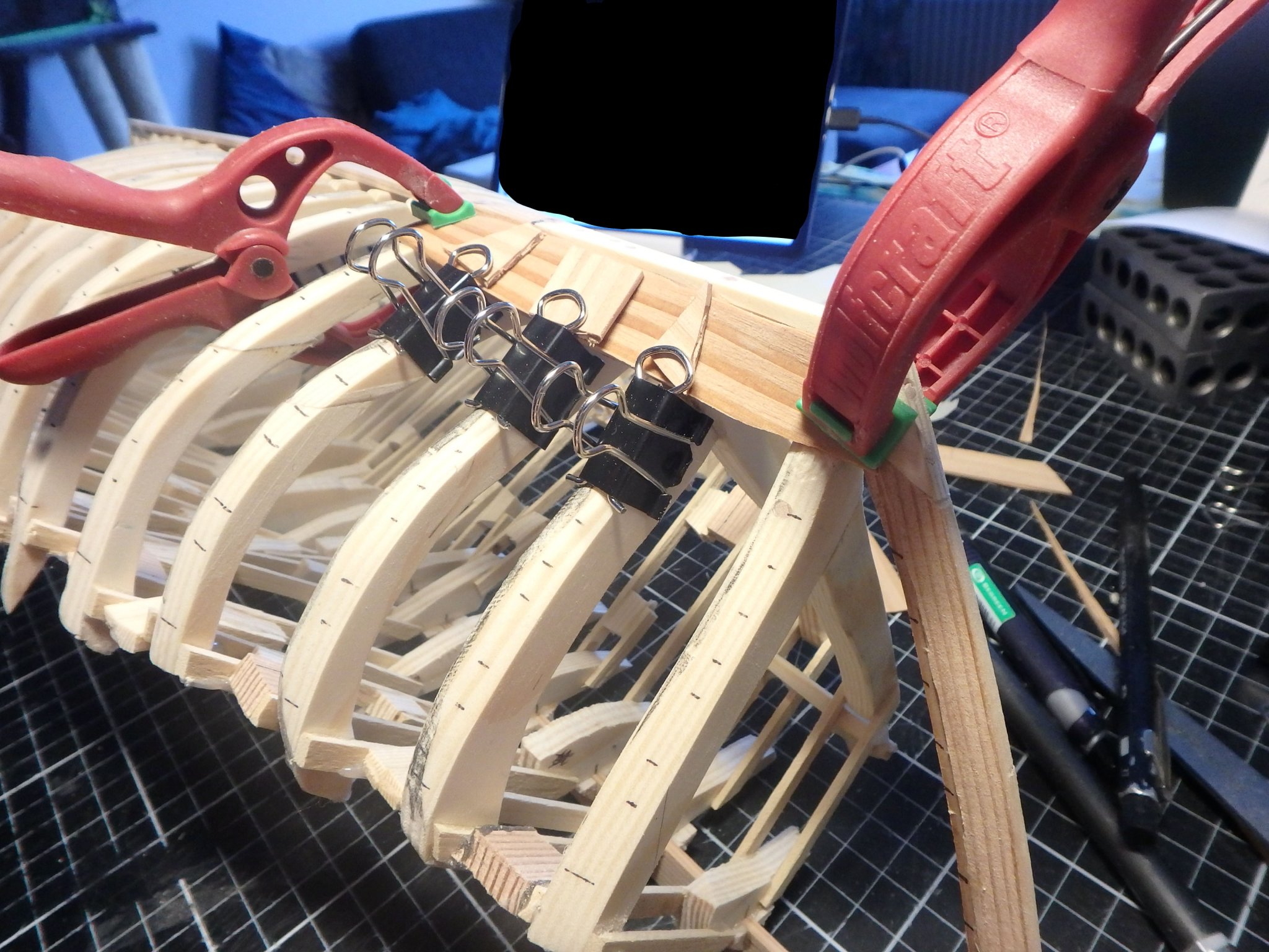
After doing some more strakes and only having the shear strake left it was time to cut off the super structure. It had played it's role to make the hull solid as I planked. I tied the clamp as a guide for sawing.
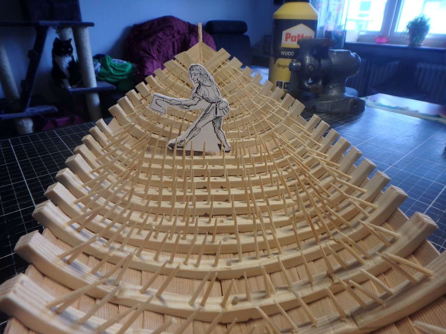
Lots of treenails to trim... You can see how one of the cats is eyeing the boat and can't wait for the spikes to be removed so she can use it as a bed.
And after fitting the clamp and shear strake the outside of the hull is nearly done.
Changed plans for the decks. After reading up a bit more I will have a shelf running from stem to stern for beams to rest on and then standing knees on top of the planks. And gangways running alongside the cargo area.
Next step is smoothing out the inside of the frames.
- druxey, bolin, Chuck Seiler and 5 others
-
8
-
PhilB, thank you! And yeah, I'm also wondering of the decking. There will be a front and aft deck. But I havn't decided on the exact placements yet. I think they will be held by beams with hanging knees. I always thought the decks should lay horizontally, but I read something about them following the shear? The deck planking will anyway be wide planks with natural edges. And the cargo area will have ceiling with some spacing between the planks.
You really should try planking like this, it's really fun with new challenges all the time.
Liteflight, yes, that bamboo graining is horrible! I started out with beech, but it was much easier to adjust the width of the bamboo sticks without them breaking.
-
Thank you Binho and Liteflight! And thank you everyone for the likes 🙂
When I was back at the hobbystore to buy more planking I saw that the timber in my dimension was made in two batches with completely different graining patterns. Now I bought the good looking timbers instead.
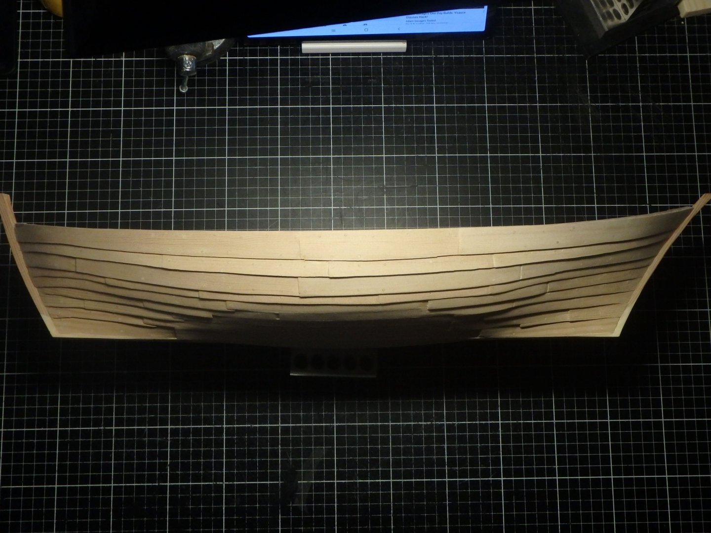
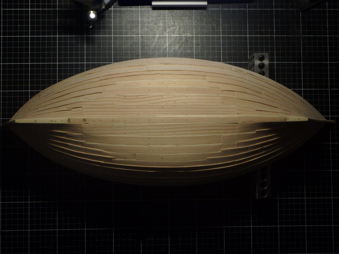
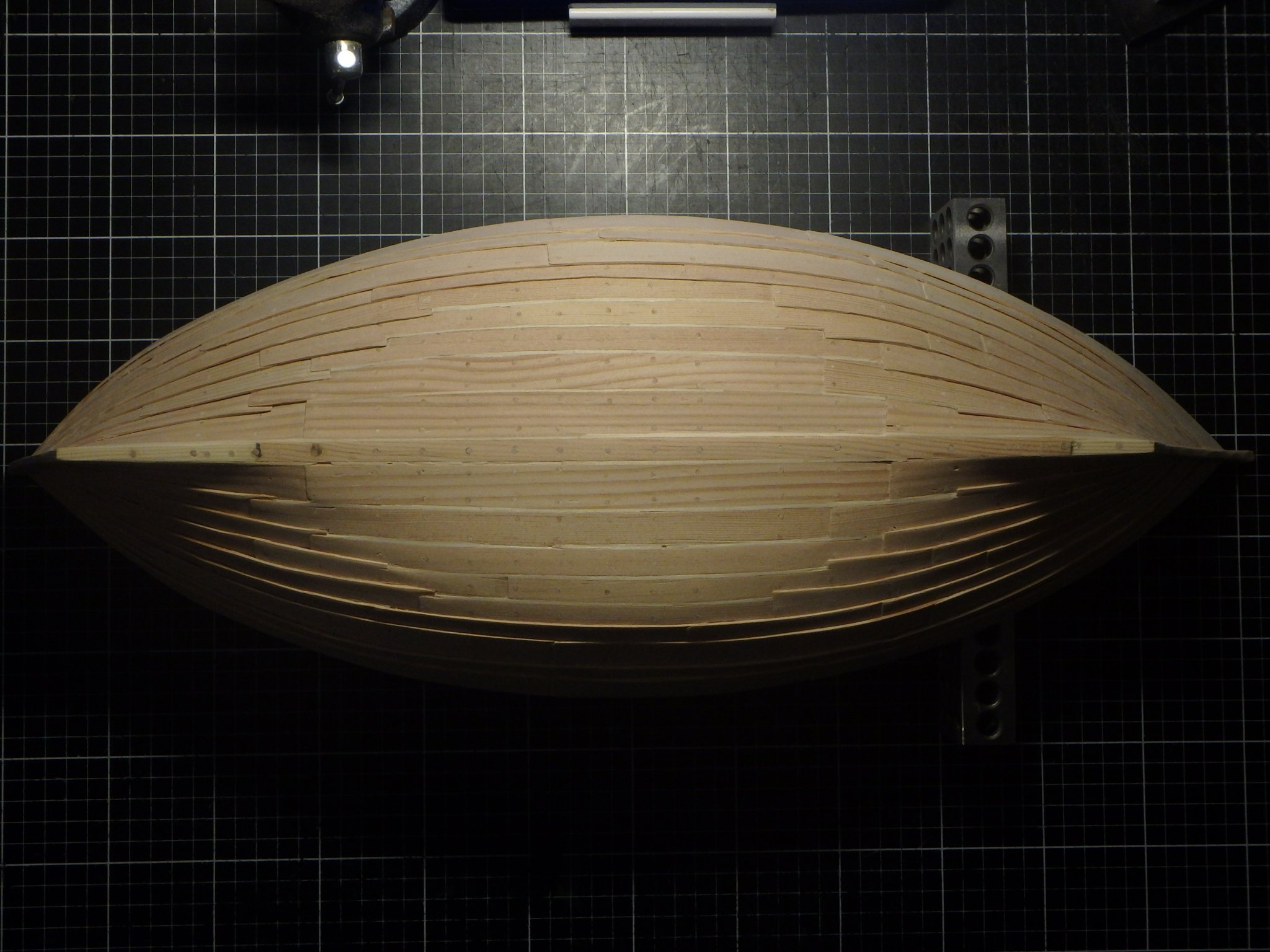
The planking continues. I think the boatbuilders would have prefered to have it all clinkerbuilt for extra strength, but that extensive beaching would damage the hull, so they made the part of the hull contacting the sand flush.
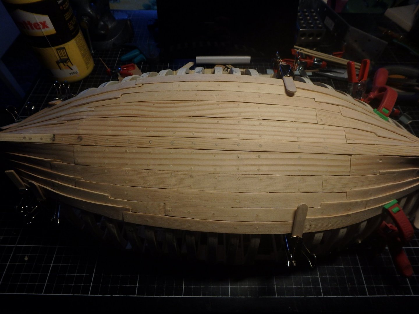

The wreck had the line between flush and clinker looking random, but I made it more even.
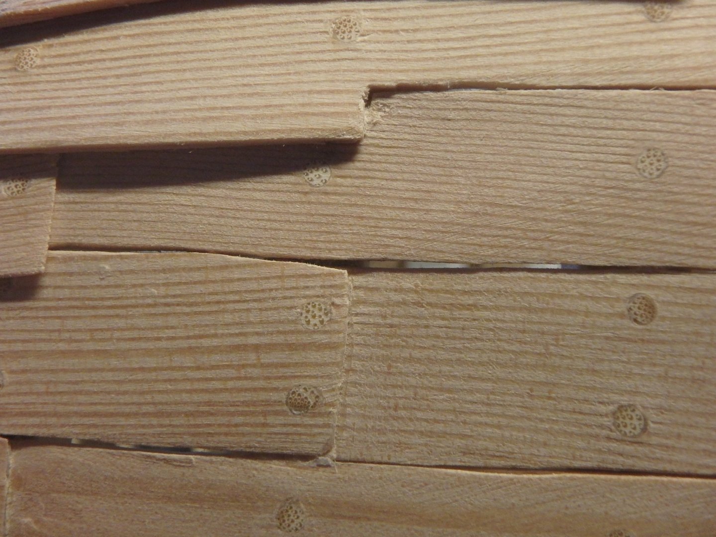
I wasn't very precise when fitting the planks and some gaps was unsightly.
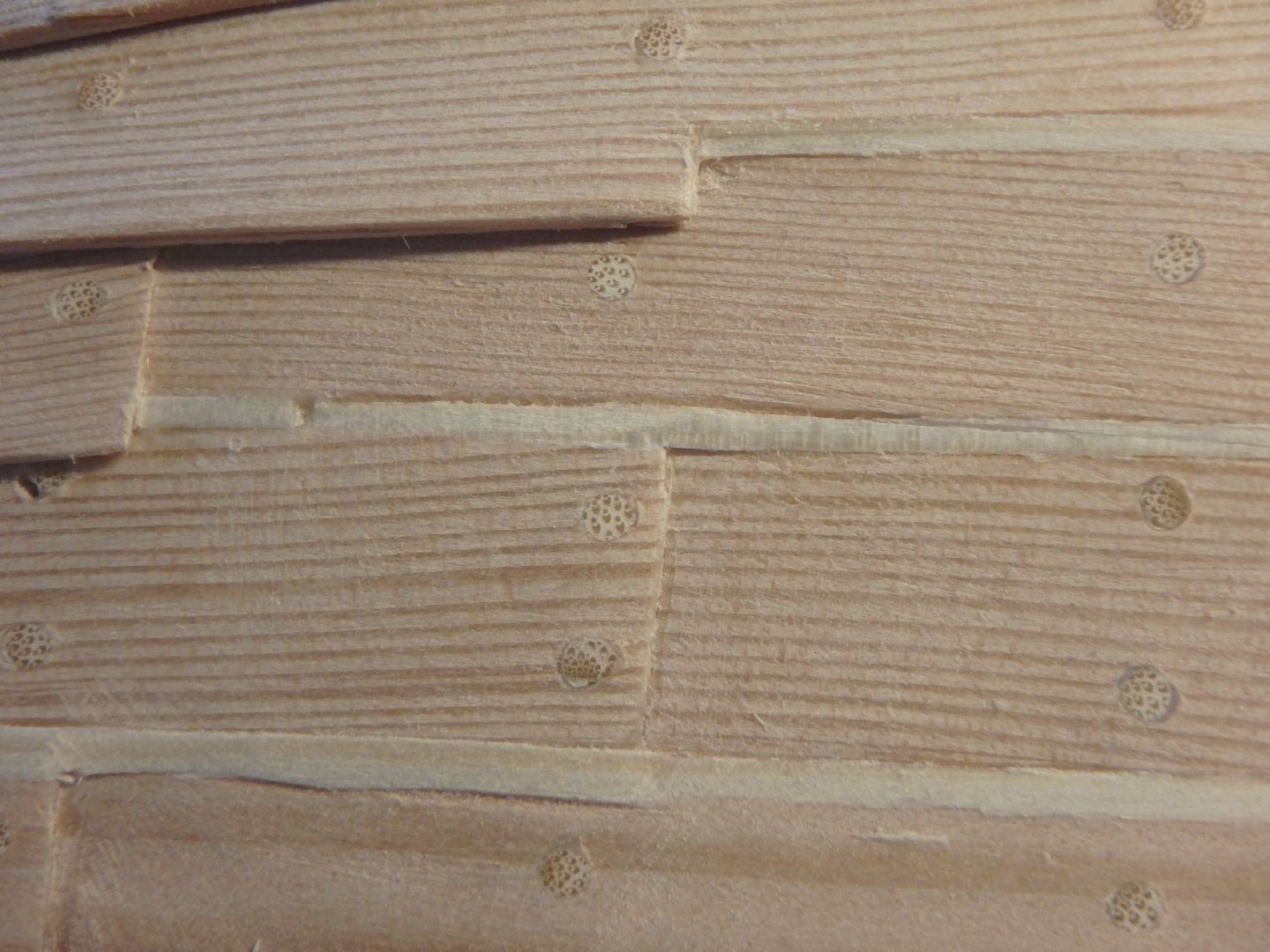
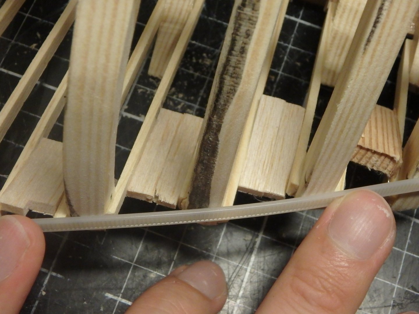
The ship was caulked from the outside in grooves between the planks that were covered up with mosslaths. I thought I had read they were 3cm (1 3/16"), but after building it I looked it up again and saw that the were just a third of that. Oh well, I guess the mosslaths can be oversized if the treenails are...
It would be nice if I also could make the butterfly clamps holding the laths in place.
- Binho, mtaylor, GrandpaPhil and 2 others
-
5
-
Amazing work on the oarsmen! They really make the model pop. We'll see if you in a week's time decide that you also need men for the lower deck 😉
- Louie da fly, mtaylor and Keith Black
-
3
-
Steven, thanks, and it's the same timber as the rest. And yeah, it's a bit too visible. But it's ok - I really like the idea for this project of simply using the simple materials that I can source locally. The next model will have better timber and I can then compare the difference.
Kent, thank you. But I'd rather have this kind of forum where people give critical, and constructive criticism, then just telling you that all you do is great.
- Louie da fly, mtaylor, Binho and 1 other
-
4
-
Thanks Steven!

Before lining off I had to mark the shear. I clamped a wide plank to get the line as straight as I could.
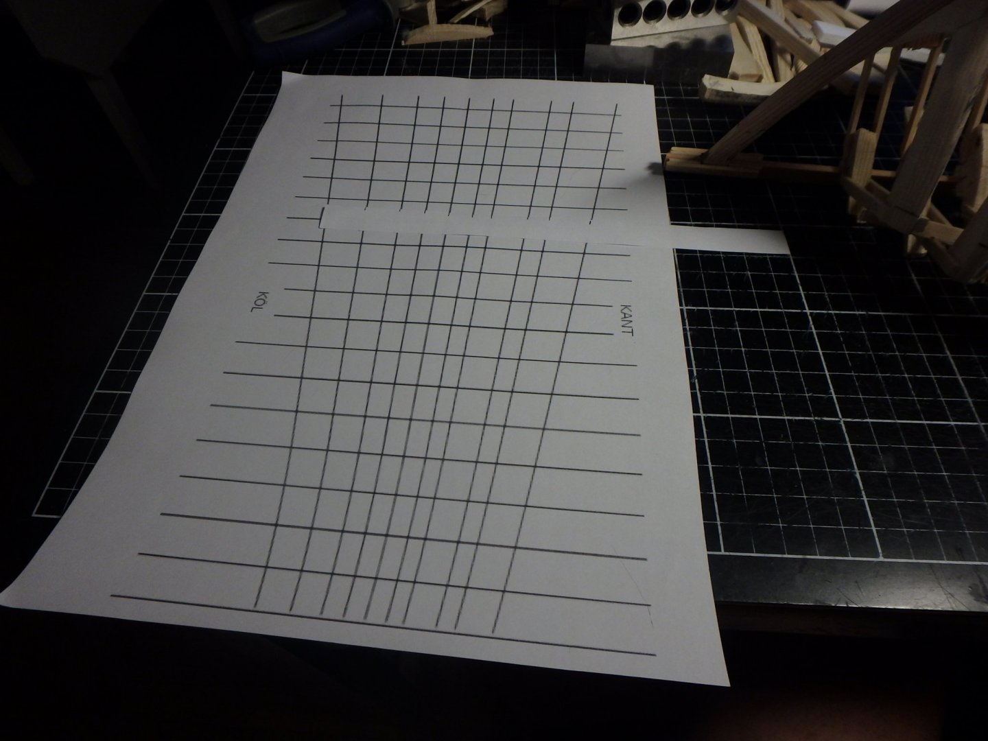
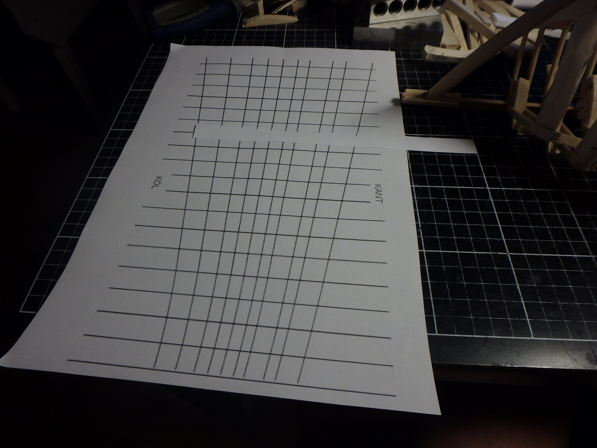
I have seen people use this kind of template for lining off and made my own to get the different strake widths correct.
All frames lined off.
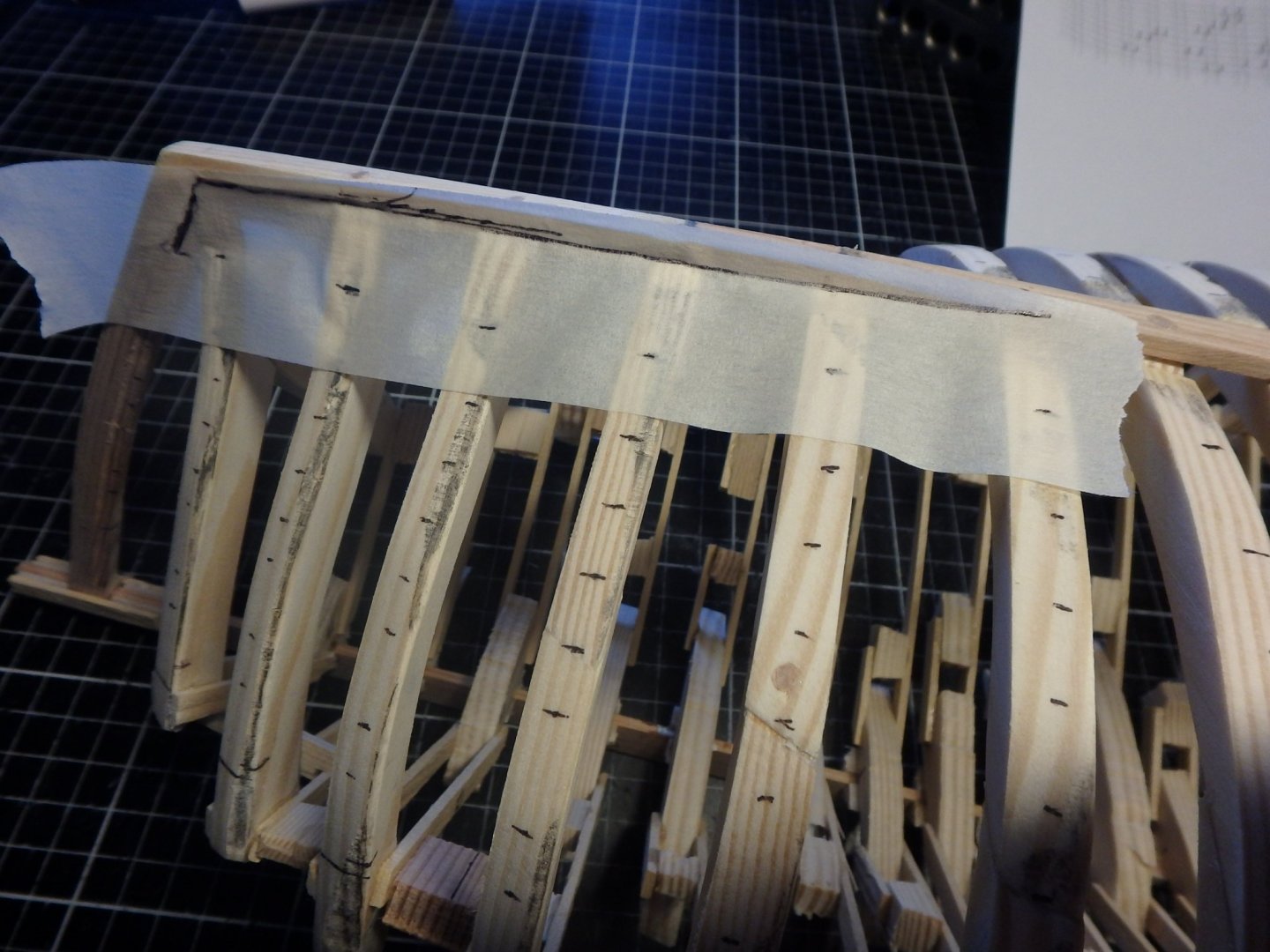
I made templates for the planks using masking tape.

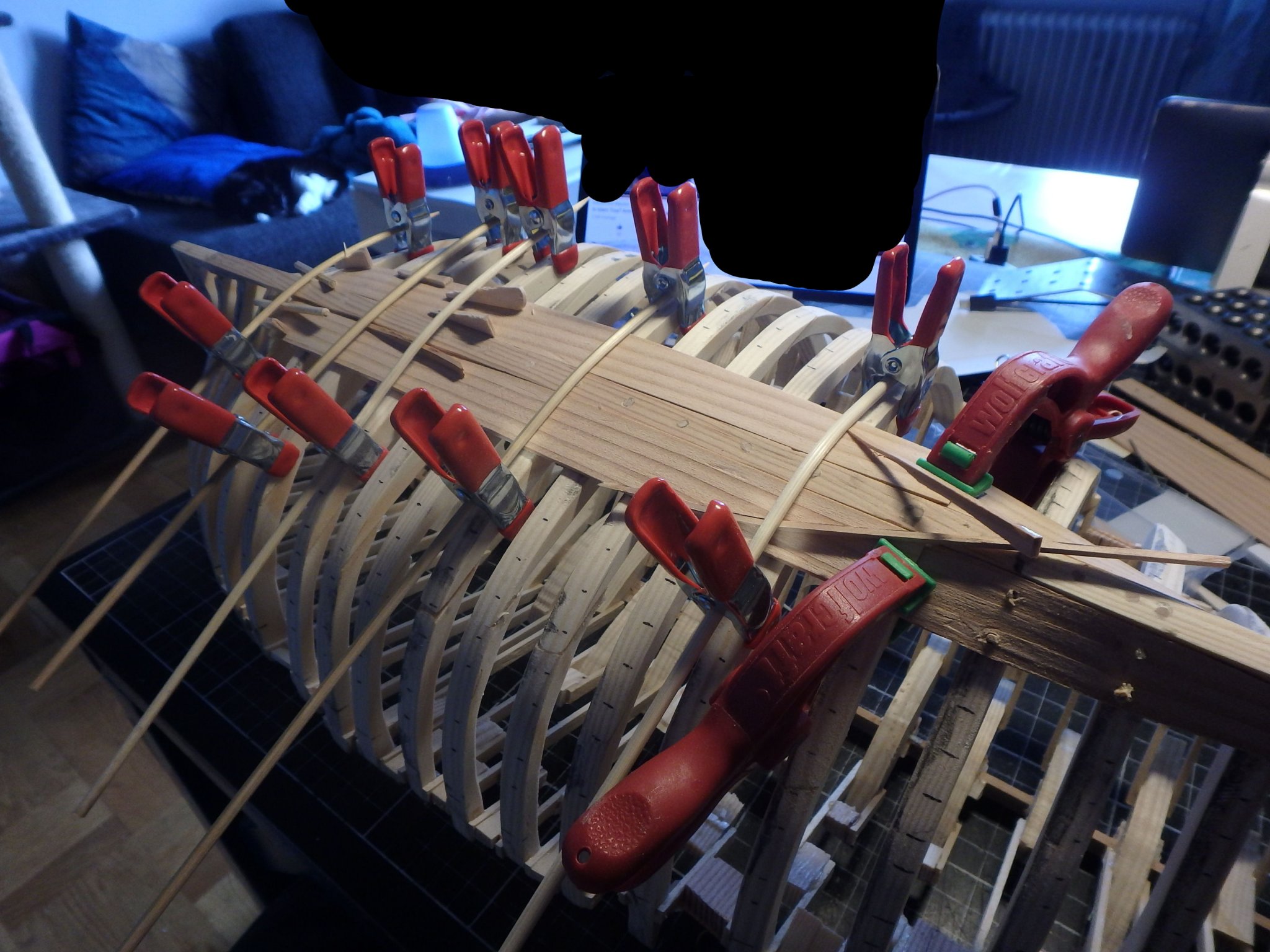
Planks held in place with lots of clamps
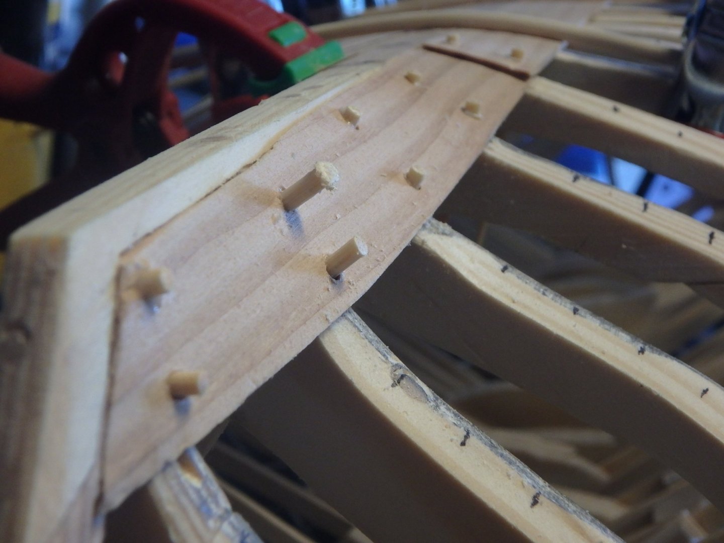
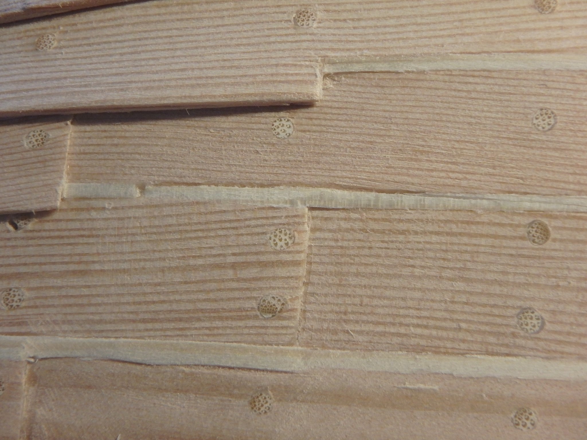
Treenails made from bamboo toothpicks corrected in size using my home made drawing plate (fancy name for a hole drilled in a steel plate). They are functioning and sticks out on the other side.
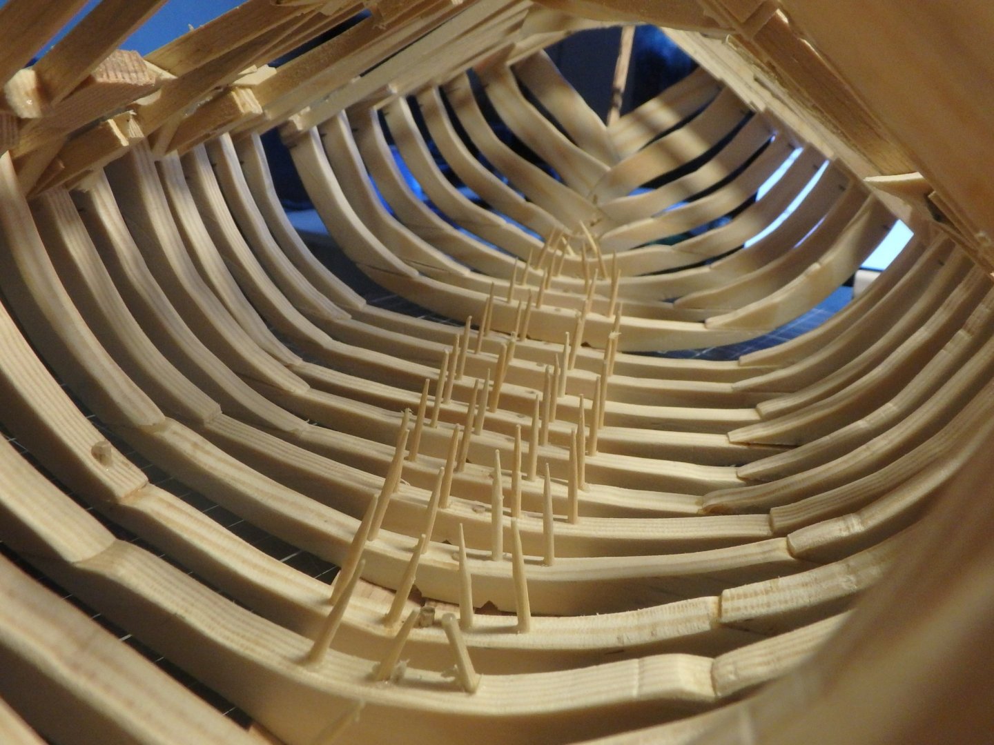
The inside will look like an inverted hedgehog when the planking is finished.
Gardboards are done! I try to mimic the placement of the joints of the planks in the strakes with the original's. They were sometimes placed between frames, but I will have them all on top of frames to make it easier.
- BLACK VIKING, Chuck Seiler, Baker and 8 others
-
11
-
Fairing the hull was easier than expected. I thought I would have to do it by hand, but the model was sturdy enough for using the orbital sander. Two mistakes happened. A scarf joint broke between a floor and futtock, but that was an easy fix. Next thing was that a frame proved to be too small. So I had to cut it off and replace with a bigger version. I had marked the sides of the frames with pencil before sanding so it was easy to see untouched parts and you see how this frame simply was too small.
The new frame looked better.
Those ugly blocks are temporary structures above the shear that will be cut away after planking.
Next up is lining off.
-
Yes, the shipwright is from the late 15th century and I also cut out his colleague and their master.
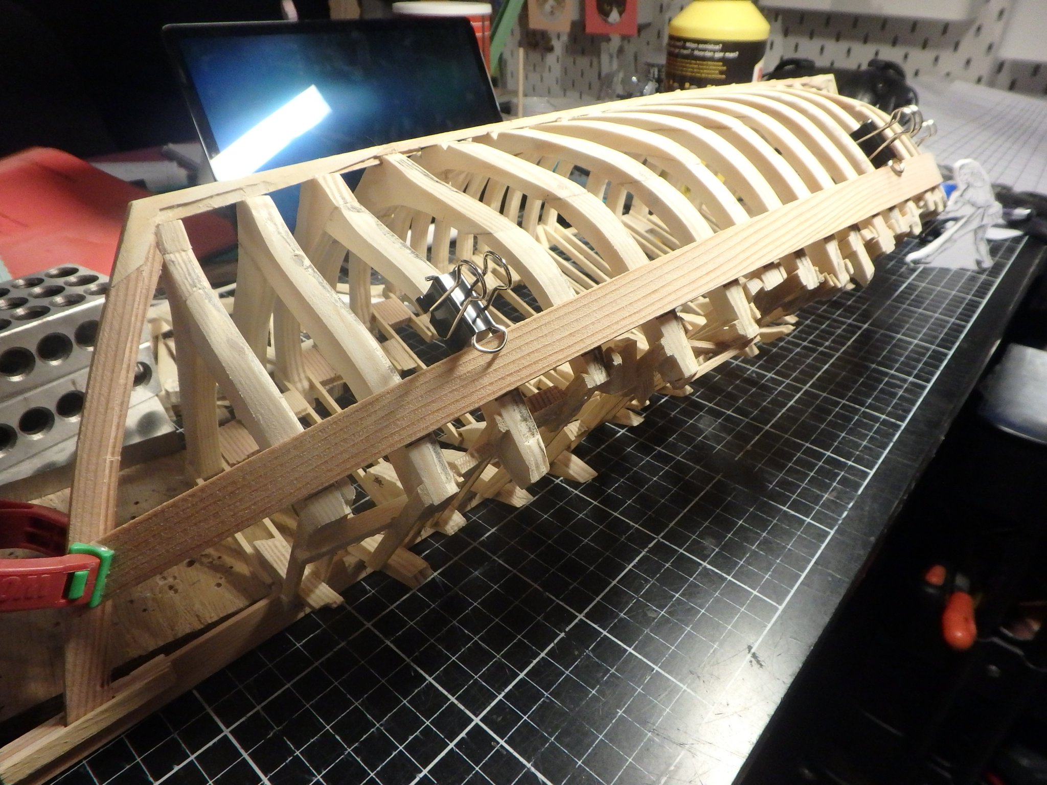
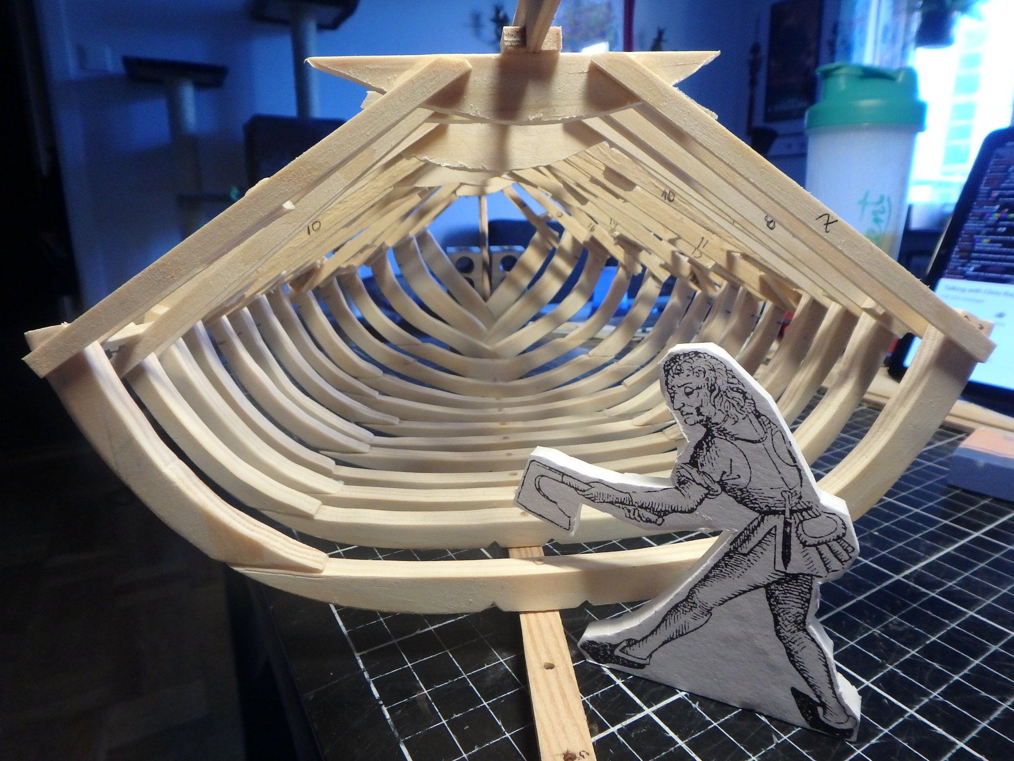
All frames are all in place now. I'm really looking forward to smoothing it out and it feels really solid. The shape shows what a slow cargoship this must have been.
- GrandpaPhil, bolin, bigpetr and 3 others
-
6
-
Thanks forthe links Louie! I have not read these and they seem to contain interesting bits about the decking.
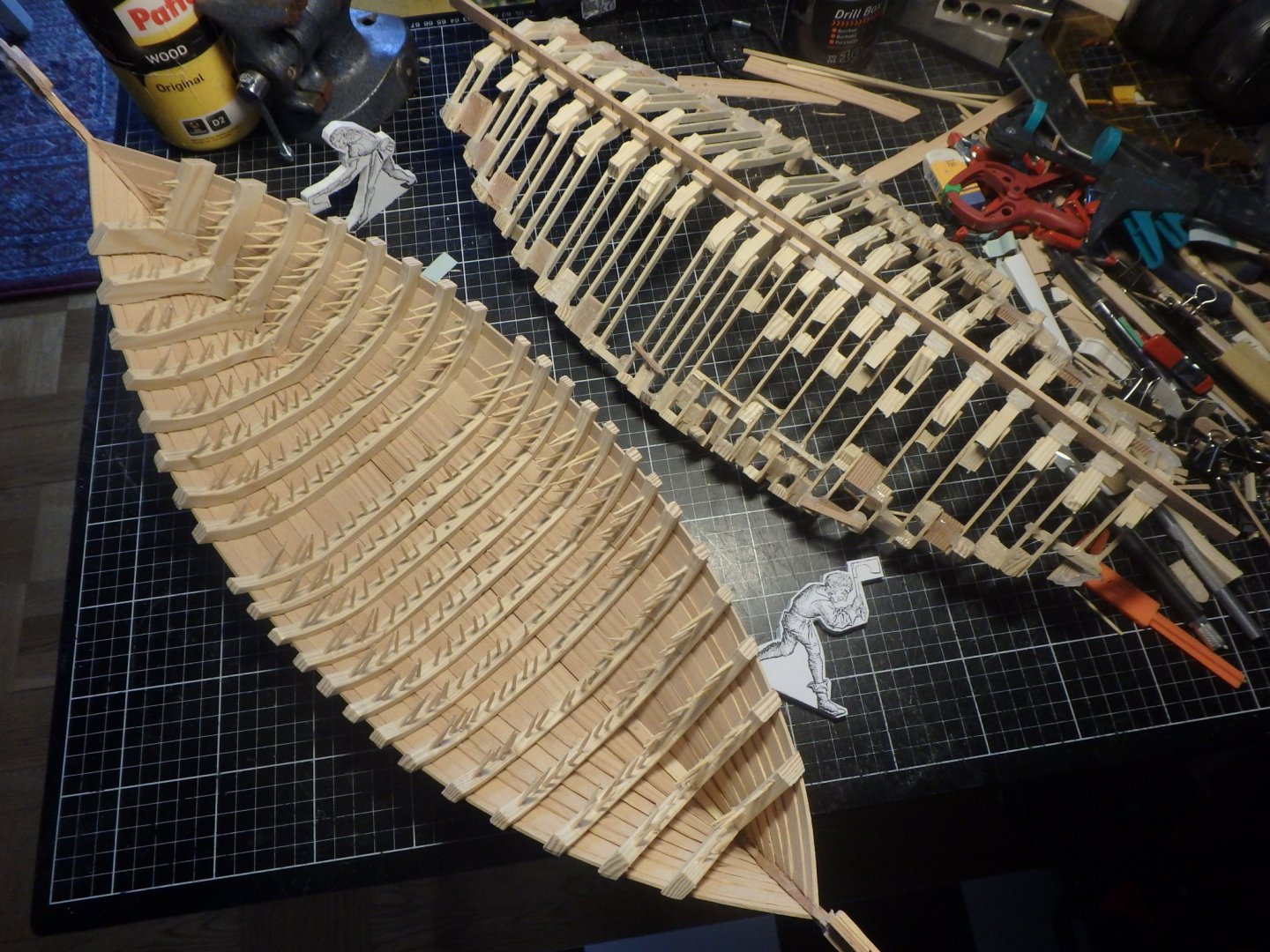
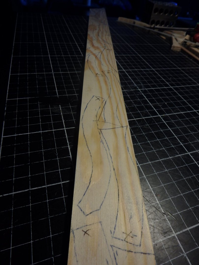
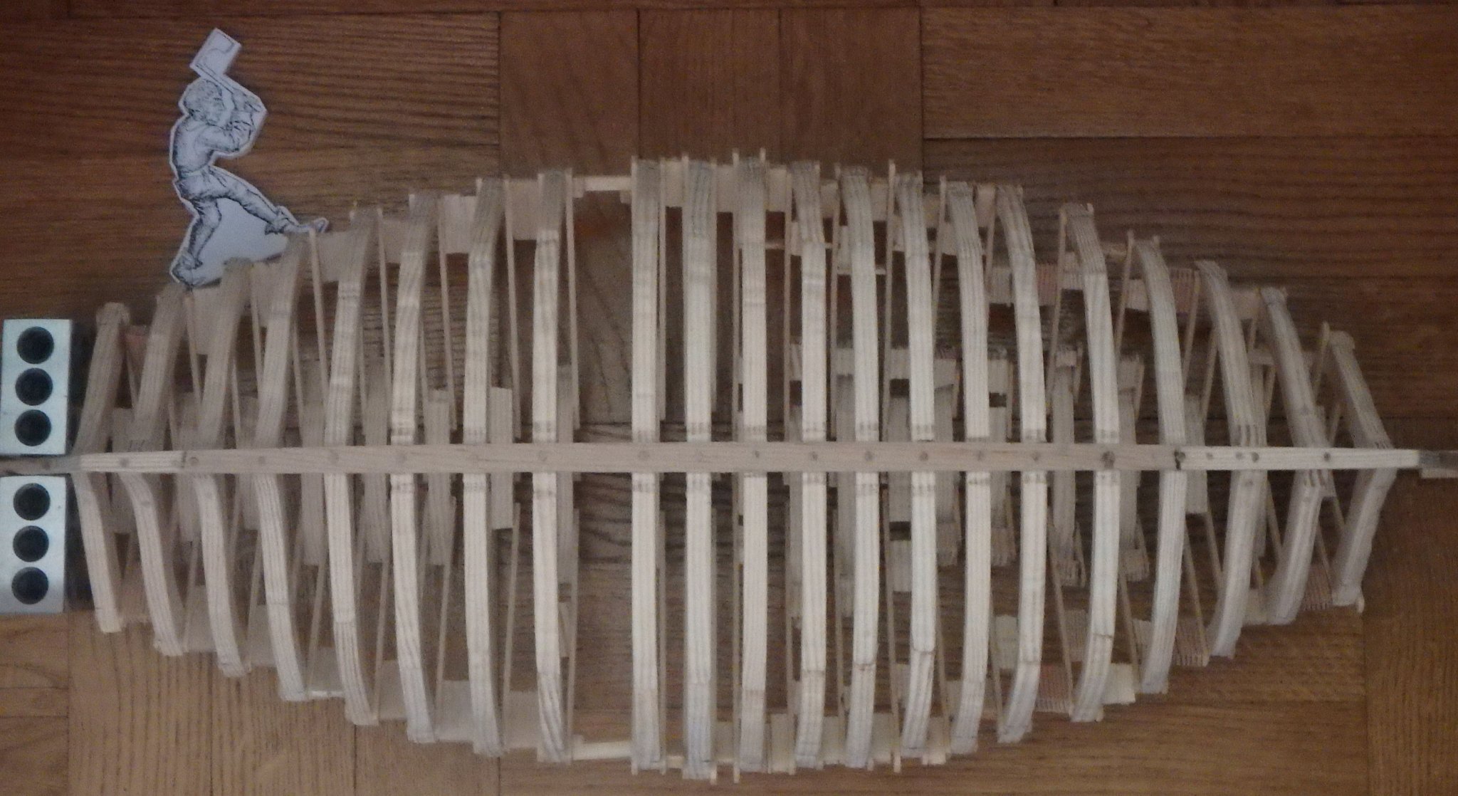
There's not much to report on the build, the framing continues. I printed a couple of figures to have as size references to get a better feeling of the scale. Usually I just work on one frame at a time, but now I drew all remaining on the wood as I don't think that neither my girlfriend or neighbours much would appreciate sawing at 6 am on a sunday.
The framing looks uneven. Which it should. There are three different spacings between them and one extra big gap where the mast steps are.
One of the frames got a bit big and that will be taken care of when smoothing them all out and making the bevels.


-
Thanks Louie, your collection on pinterest looks like a great resource when searching for references!
- Louie da fly and mtaylor
-
2
-
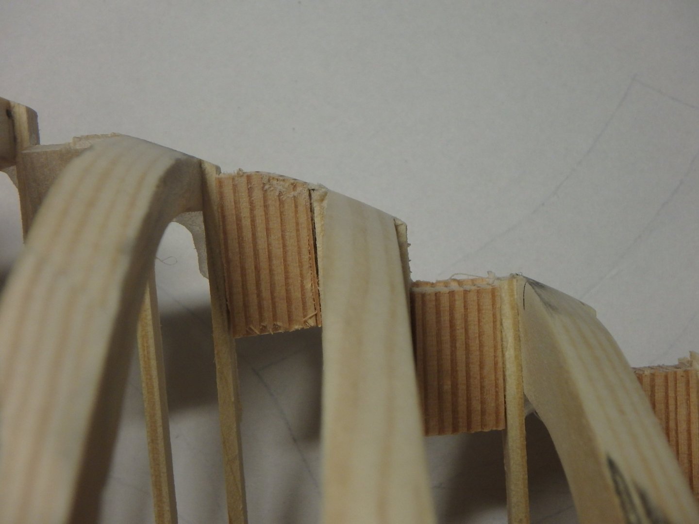
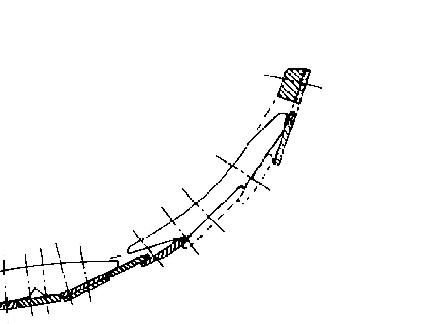
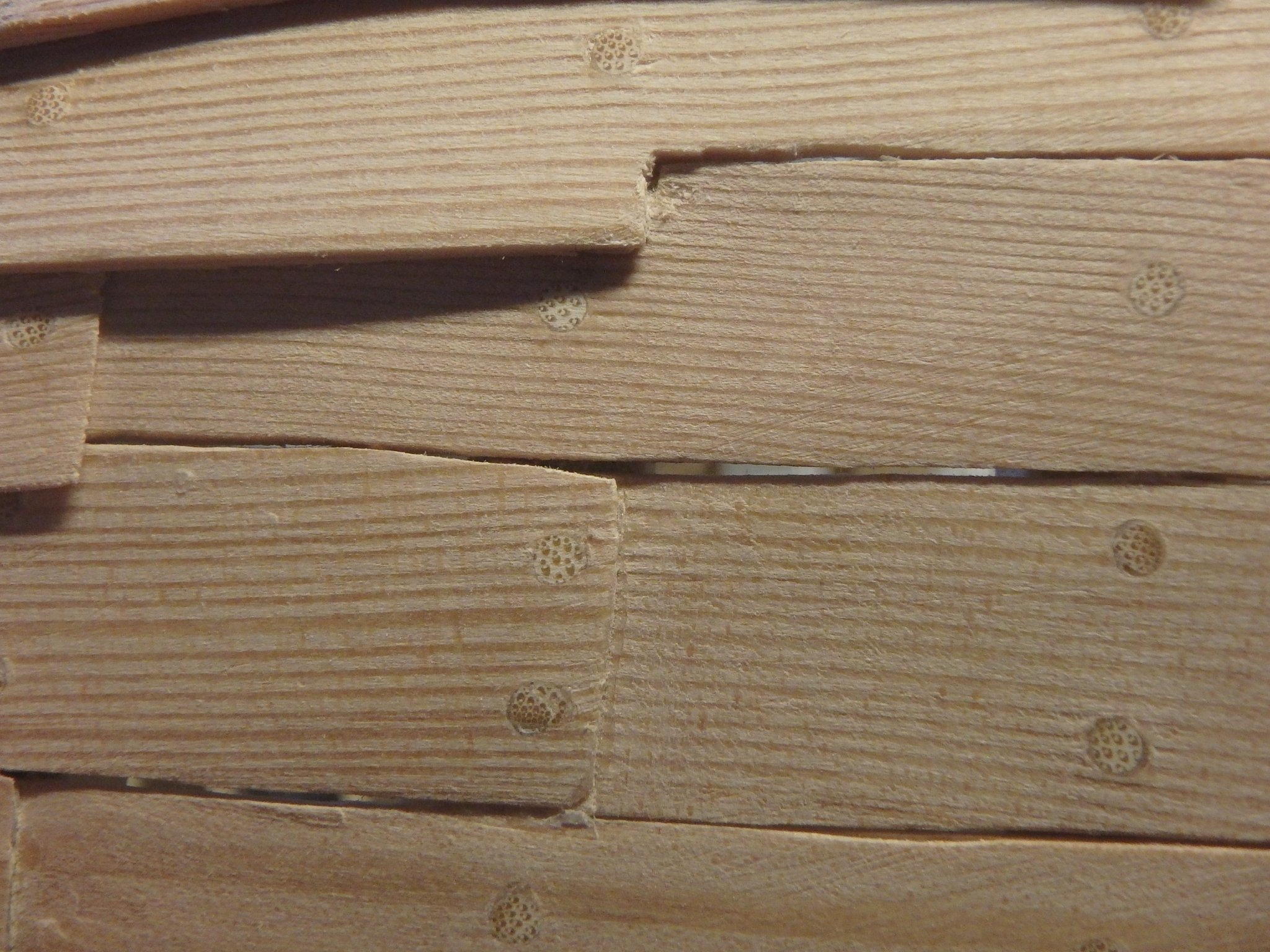
Here is a diagram of how the transition mid-strake from flush to clinker was made
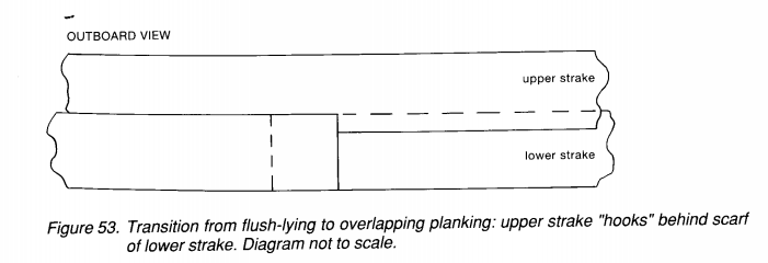
Some of the transitions were like this where a plank suddenly got wider to overlap the previous one, but in other places this transition was made at scarf joints where the builder just added a wider plank.
Regarding contacting the author I'm sure she would be suprised to hear from somebody reading her 30 year old thesis!
And regarding how there was a transition in this period from cog to caravel - I'm a big fan of how the thesis doesn't say that this was cog, just that it is cog like to not be bogged down in discussions about defintions.
-
Jaager, thank you very much for your thoughts. That's one thing that really impresses me of this forum - how much well thought feedback people give.
Wood: Yes, I'm beginning to see your point. One reason that I use fir is that I'm a bit sick of how hard oak is from some other projects. But something inbetween might be a better chose. Such as pear as you suggest. I will think about it.
Planking: from the thesis
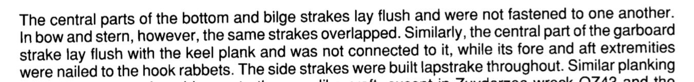 and at another place it says that these strakes get flush again at the rabbets.
Frame first: That was my first plan. But I'm afraid I will get to much internal stresses in the planks that it will deform the shape when I remove the plug.
Draw plate: I will look what a Byrnes draw plate costs in europe, but your idea of drill gauges sounds as an alternative! I did a quick test of just drilling holes in a steel plate, but I'm not yet sure of how that turned out.
Interesting thoughts about bamboo. Somehow I just thought it was all the same kind, which it of course is not.
- Keith Black, mtaylor and Louie da fly
-
3
-
Bolin, tack!
The thesis that I use as my main source can be found here. I do not know if you need to register or not, but it's free anyway
https://www.academia.edu/19352324/A_Cog_Like_Vessel_from_the_Netherlands
- Keith Black, mtaylor and Louie da fly
-
3
-
3 hours ago, woodrat said:
I applaud your choice of subject and have something of a penchant for the working mediaeval vessel myself. I am happy to see you are referencing the excavation report. Do not hesitate to contact the archaeologists as they will undoubtedly be keen to assist you. Those trenails seem a little oversized. Does the thesis give information on their diameter. I find Byrnes trenail maker very cheap and easy to use to get accurate diameters of trenails (I use split bamboo to make them).
Good luck with your build of a very interesting vessel.
Cheers
Dick
Yes, I think too that they are a bit oversized, but the report actually says that the biggest ones were 4 cm. My local hobby store didn't have thinner, but I should defintly look into using a draw plate to make smaller ones, thank you!
- mtaylor, Keith Black and KentM
-
3
-
3 hours ago, Louie da fly said:
Nice to see another mediaeval ship, Silverman, and nice to see another cog! I take it you re-enact 15th century stuff?
You're already well into it, and the model is already looking very good. I like the fact that you're basing it so firmly on research and archaeological finds.
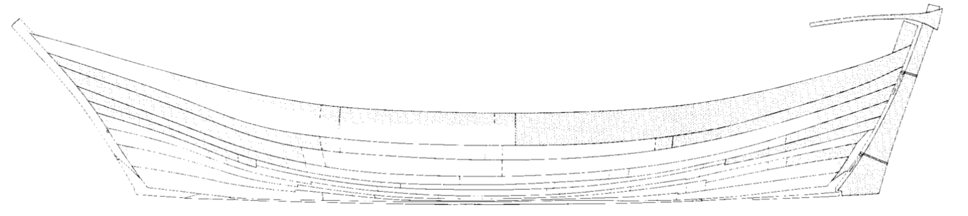
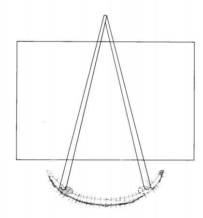
A bipod mast on a cog seems very unusual. What does the author base that on?
Thank you, I really like to use good sources for my reenactment. I started out with early 14-century, but am switching over to 15th century as they had nicer accessories then.
Yes, the bipod mast looks unusual indeed. I'm not fully convinced by the author, but I roll with it as I like the look of it.
The wreck have two heavy chocks where the mast step lengthwise should be, but far to the sides and she argues thus:
The seal that she refers to looks like this

(But I honestly think that it also could look like shrouds)
- Keith Black, Louie da fly, mtaylor and 2 others
-
5
-
Hello, I just found this forum and find lots of information that help in my build, thank you very much. And perhaps I then also should make a build log of it.
It is a scratchbuild of a small cog from around 1410 and it will be my third boat model and my first scratchbuilt. A month ago I started to watch the Youtube channel 'From acorn to Arabella' where they build a wooden ship and it made me also want to build one, but I felt that I don't have space for anything much bigger than around 2'.
I dabble in medieval reenactment, so I wanted to find a ship from the 15th century and it must be small so the scale will be large so the wood working details will not be too small.
Looking around I found a list of medieval wrecks and simply chose the smallest one from the correct time period. It was called NZ43 and was 11 meters or 36 feet. And then I found the thesis work 'A cog-like vessel from the Netherlands' not only describing the wreck in detail but also hypothesizing on how it might have looked when used. (it looks a lot smaller in this image, but the sailor stands on an aftdeck to control the tiller)
Two of the most striking features that the author hypothesizes about are the bipod mast and the boom for lifting cargo. The planking will also be very interesting and challenging as some of the strakes will be flush midship, than lapstrake and than go back to flush in the ends. Let's see if I will be able to do this. And the strakes are of different widths which I think will look interesting.I chose the scale 1:20 as this would land the size to just under 2' and it will mostly be built in fir as I live in Sweden and it's readily available everywhere.
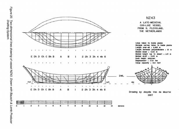
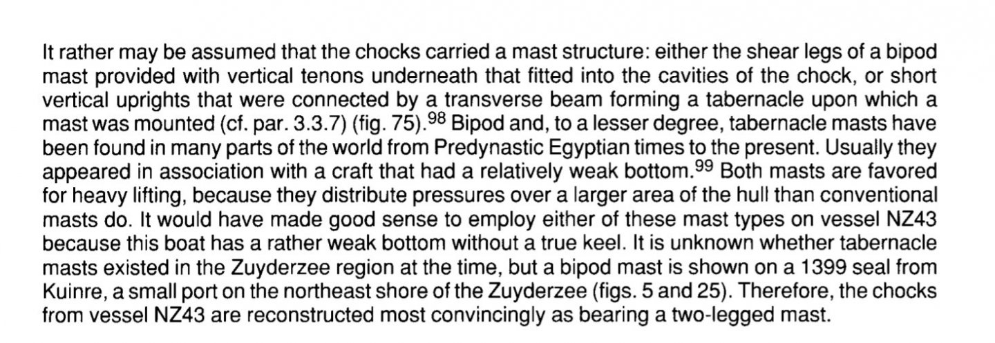
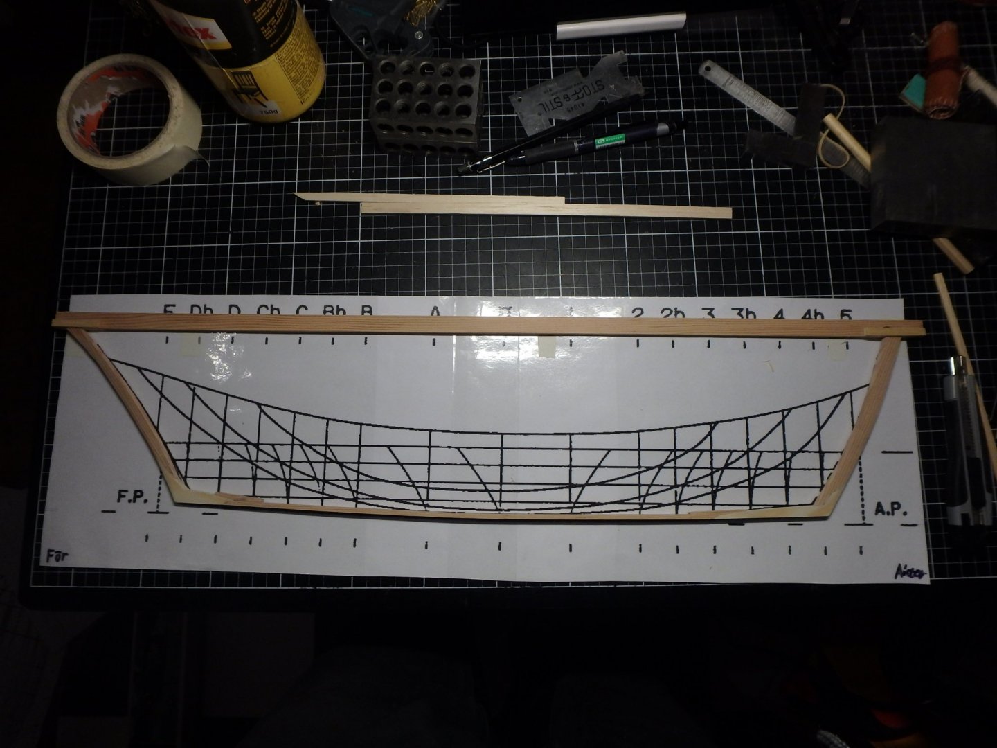
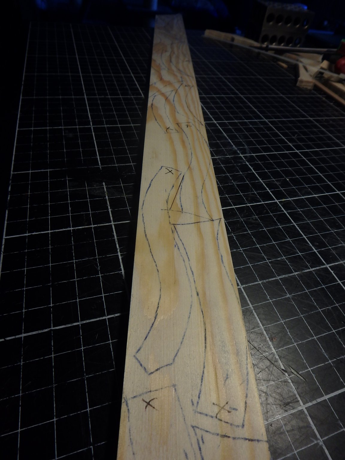
The first step was to make plans. The thesis included this plan, but the sections just tell you the final shape of the hull and not what each frame looks like. (the thesis is readily available from the web, but I compressed the plans any way in case somebody worries about copyright infringement)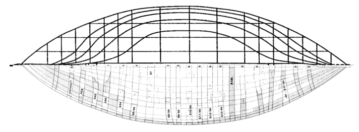
This illustrates where the frames are and where the sections of the plan are. They do not line up.
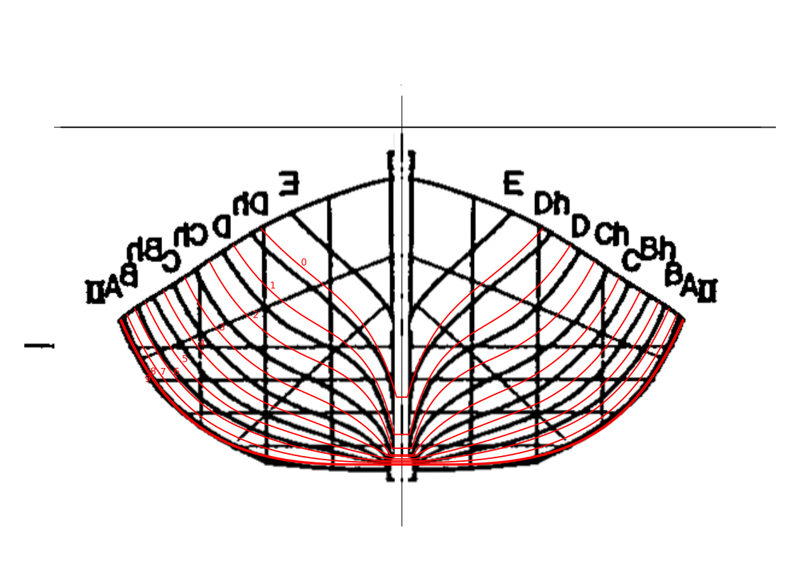
I imported the sections into Inkscape and extrapolated the shape of the frames. The black curves are the sections from the plan and the red ones are my frames. The general shapes are from the drawing, but how they connect to the keel plank is based on measurements of my model.

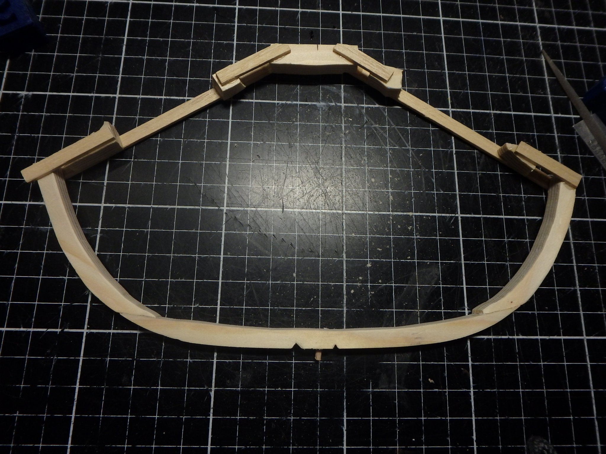
The midship frames are made out of three pieces, floor and futtocks, and frames towards the ends just have the futtocks. Scrapwood is added as support. Some of the joints are also reenforced with treenails. I think that only the floors were sawn in the original and the futtocks were bent to shape, but I'm sawing them all.

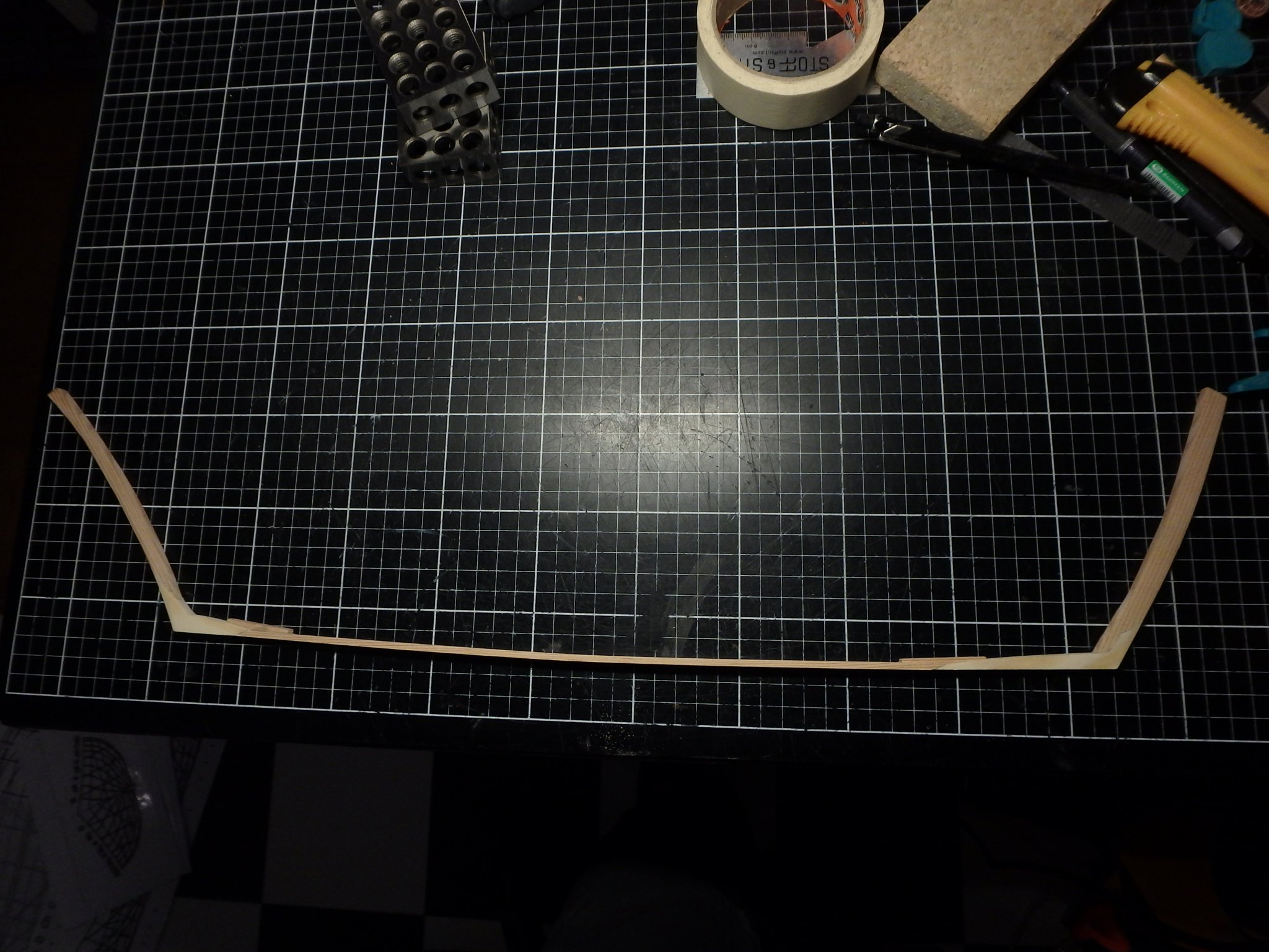
The spine of the ship consists of stems connected to the keel plank via hooks.
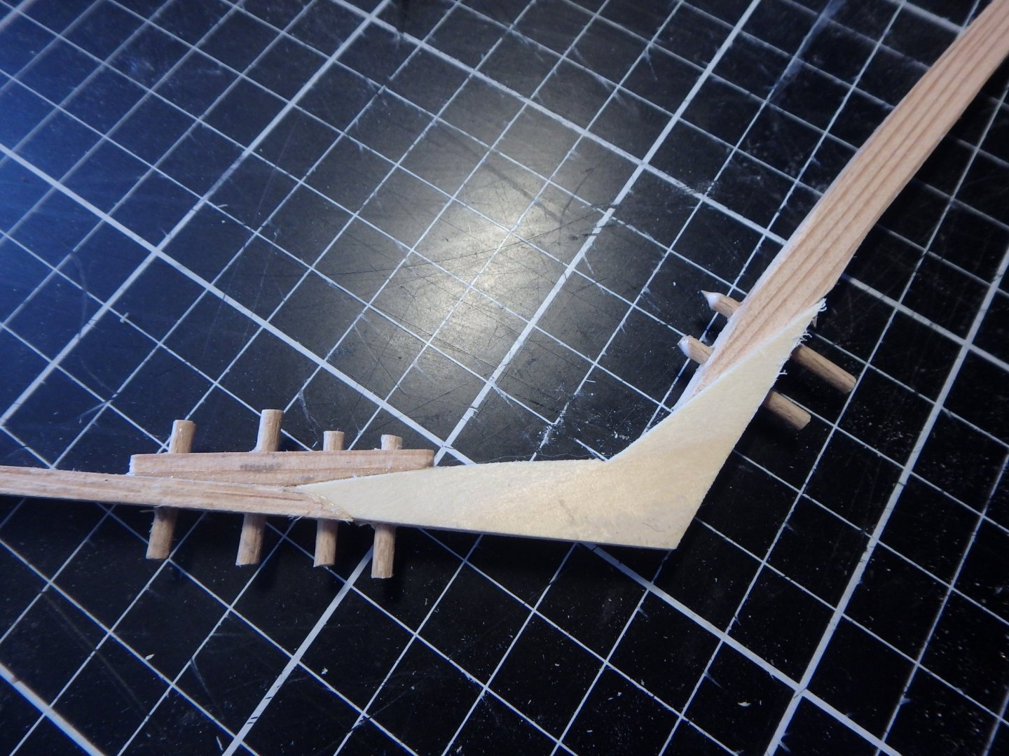
The joints are reenforced with treenails.
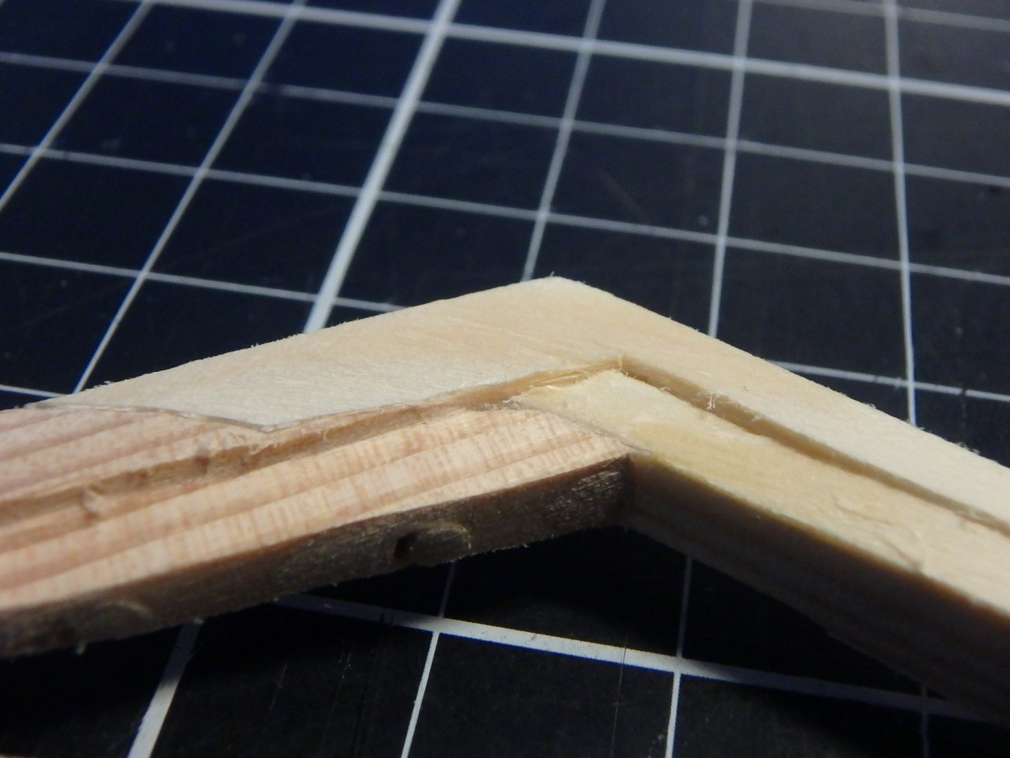
Rabbets are cut for the planks in the stems and hooks.
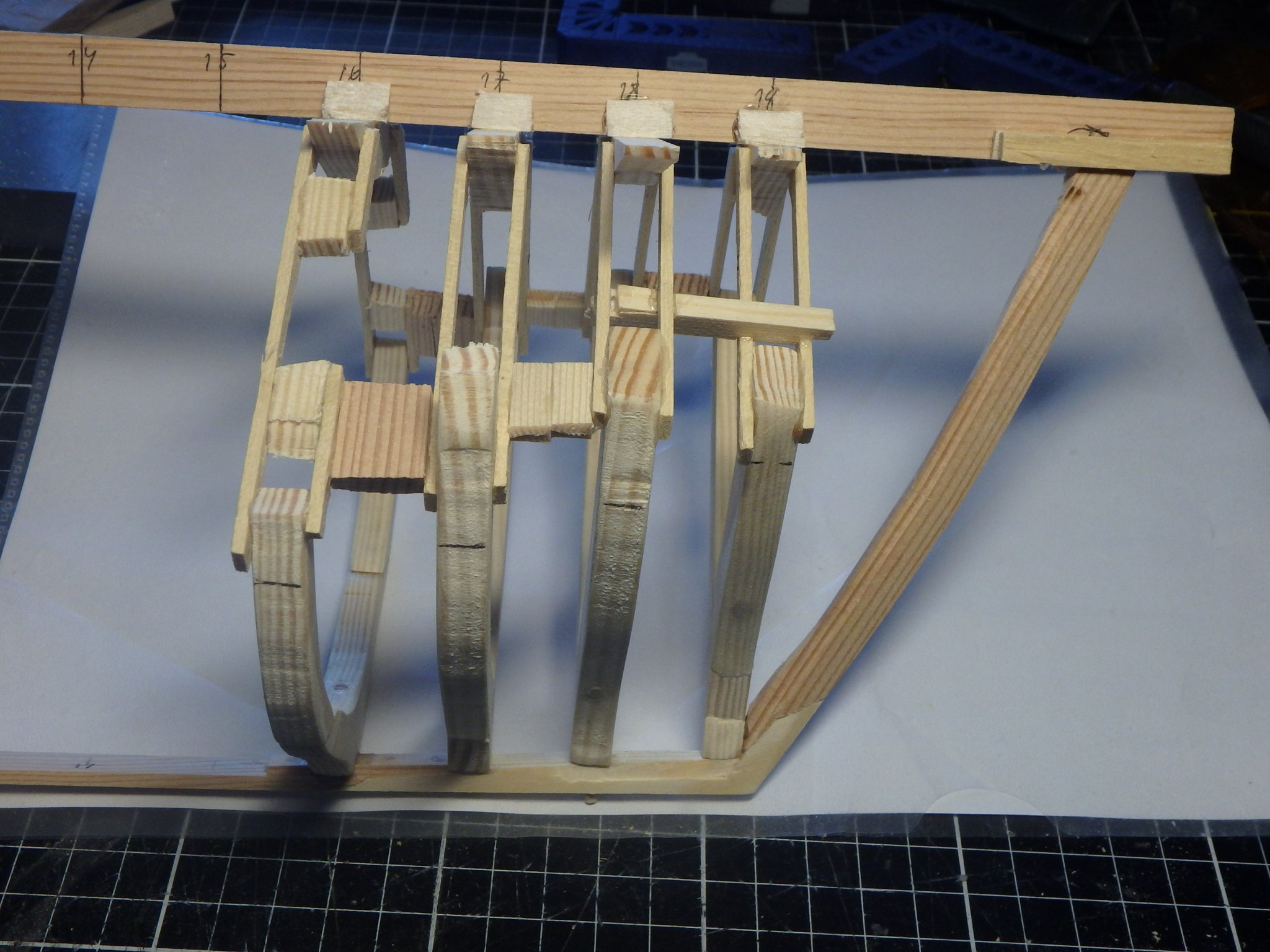
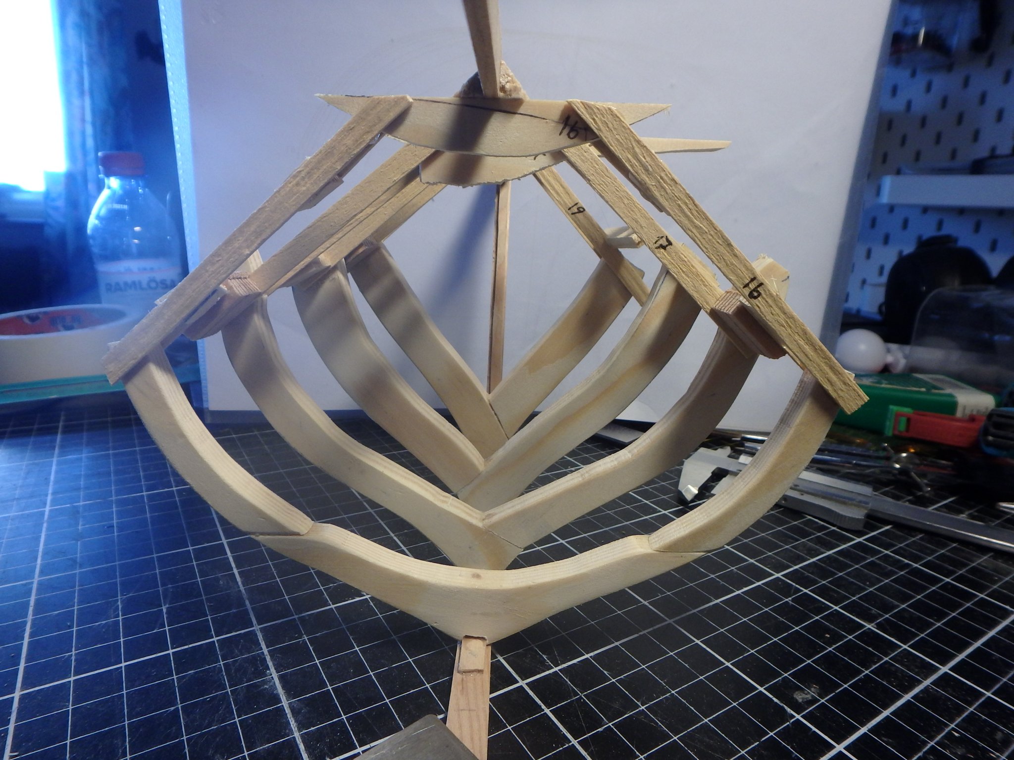
I have to reenforce the model with something sturdy to fasten the frames to as the boat just have a flimsy keel plank and not a real keel .

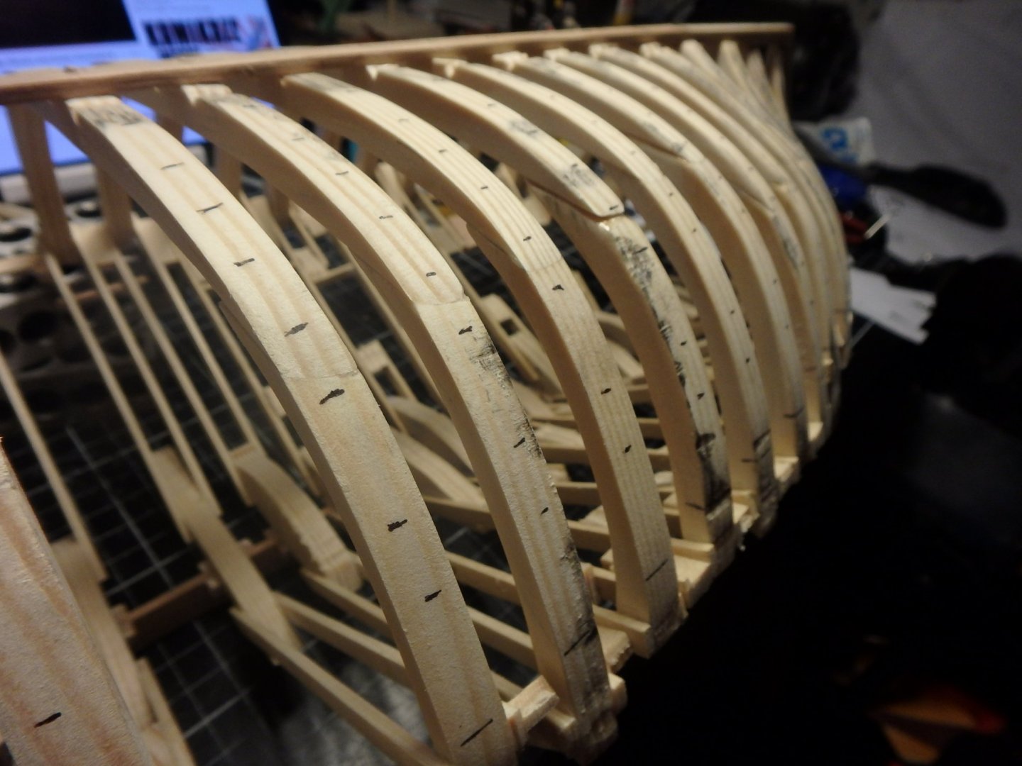
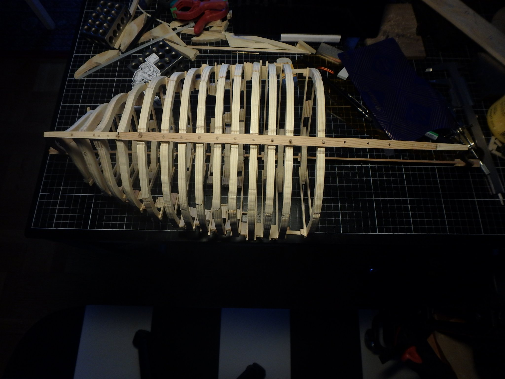
The frames are glued into place with wooden blocks connecting the frames. The lines on the frames show the top of the sheer strake and where the frames will be cut.

You can see how the frames get thicker towards the ends, this is based on measurements from the wreck.
The frames are not yet chamfered. I thought about doing it before fastening them to the model, but decided to try to do this afterwards with a dremel. Let's see how that works out...
-
-


A small cog c. 1410 by Brinkman - FINISHED - scale 1:20
in - Subjects built Up to and including 1500 AD
Posted
Thank you so much Phil for your kind words! Yes, I agree that it will look wrong with this kind of nails in smaller scales, this scale is just on the edge I think