


AnobiumPunctatum
-
Posts
1,267 -
Joined
-
Last visited
Reputation Activity
-

 AnobiumPunctatum got a reaction from James G in HMS PEGASUS by giampieroricci - Scale 1:36 - Swan-Class Sloop from plans by David Antscherl & Greg Herbert
As soon as I will start with my Sloop Fly, I will use your log as further guide for my model. It is a really useful add on to the wonderful books from David and Greg.
-

 AnobiumPunctatum got a reaction from giampieroricci in HMS PEGASUS by giampieroricci - Scale 1:36 - Swan-Class Sloop from plans by David Antscherl & Greg Herbert
As soon as I will start with my Sloop Fly, I will use your log as further guide for my model. It is a really useful add on to the wonderful books from David and Greg.
-
 AnobiumPunctatum got a reaction from mtaylor in HMS PEGASUS by giampieroricci - Scale 1:36 - Swan-Class Sloop from plans by David Antscherl & Greg Herbert
As soon as I will start with my Sloop Fly, I will use your log as further guide for my model. It is a really useful add on to the wonderful books from David and Greg.
-
 AnobiumPunctatum got a reaction from dvm27 in HMS PEGASUS by giampieroricci - Scale 1:36 - Swan-Class Sloop from plans by David Antscherl & Greg Herbert
As soon as I will start with my Sloop Fly, I will use your log as further guide for my model. It is a really useful add on to the wonderful books from David and Greg.
-
AnobiumPunctatum reacted to giampieroricci in HMS PEGASUS by giampieroricci - Scale 1:36 - Swan-Class Sloop from plans by David Antscherl & Greg Herbert
I have started making guns:
-
AnobiumPunctatum reacted to giampieroricci in HMS PEGASUS by giampieroricci - Scale 1:36 - Swan-Class Sloop from plans by David Antscherl & Greg Herbert
Little metal works for the upper deck. I built myself a jeeg for rings with shanks of various sizes:
-
AnobiumPunctatum reacted to Trussben in HMS Pegasus 1776 by Trussben - 1:48 - Swan-class sloop based on TFFM
Thanks for all the likes everybody!
Here is the stern mock-up including my stern light design and the lower counter, really starting to come together now!
-
AnobiumPunctatum reacted to SJSoane in HMS Bellona 1760 by SJSoane - Scale 1:64 - English 74-gun - as designed
Hi everyone,
A long, long time since I last posted. I have been working away, but the recent pieces took an exceptionally long time to work out, and there was not a lot to show in the process.
I realized some time ago that I would not be able to install the guns on the lower deck until I completed the outboard works, since I would not be able to turn the hull on its side for painting once the gun barrels were projecting from the side.
So I was planking up to the top, when I further realized that I would need to install the catheads before completing the planking at the fore end of the forecastle. And those turned out to be way, way more difficult than I had imagined.
I first carefully drew true size projections of the catheads in plan and elevation:
When I cut them from blanks, I assumed I could just cut straight down according to the drawn plan. Wrong! The cat tails inboard are not only shaped athwartship according to the forecastle beam round up, but also beveled fore and aft according to the sheer of the deck. But the catheads outboard are beveled according to the sheer of the hull, which is steeper. This means the cathead twists as it passes through the hull relative to its tail. I went through a number of failures before I figured this out.
Before I could cut the hook scarps on the tails and cut the slot into the hull on the sides, I needed to locate the cat beam underneath. Then I realized that I would need to locate the beakhead bulkhead stantions since they score onto this beam and have to align with the vertical edge of the hull in this location. But in order to install the beakhead stantions, I would need to build the substructure for the beakhead just above the gundeck level, which meant that I had to drill the hawseholes before access is covered up here, and that meant I had to complete the cheeks outboard.
So, then onto cheeks. These also had a much more complicated geometry than I had first appreciated. They have a round-up athwartships to match the sheer of the main wales at the bow; they fay to the wales with a curve and also a slope back along the face; and they have an upward slant fore and aft to match the hull sheer. As I tried to fay these to the wales, the slightest change in holding them against the wale would change the shape needed. So I made supports at the correct angle and kept the lower edge flat, so I could reliably slide the cheek against the wale for the usual trim, test, trim, to fay it accurately. Then I could shape the lower edge of the fore and aft arm to its final form.
And voila, lower cheeks:
I don't know why this took me so long to work out these two interesting pieces, the catheads and cheeks. Perhaps because they are so prominent I took my time to get it right....
Now onto the upper cheeks and the hawse holes and bolsters.
Mark
-
 AnobiumPunctatum got a reaction from popeye the sailor in HMS Fly by ccoyle - FINISHED - Amati/Victory Models - 1/64
Really wonderful, Chris.
-
AnobiumPunctatum reacted to Seventynet in The Hayling Hoy 1760 by Seventynet - FINISHED - 1:48 scale - First fully framed model
Good Day, and thank you very much for the comments and likes. I am just about finished this project. I don’t plan to rig it, I just don’t have room. Let me start by giving a short review of what I did since last time. I have very little in the way of photo documenting the steps I took for each operation because for the most part they are unremarkable and probably of little interest…with one exception.
That is the stern lights. I struggled mightily with those and after at least three tries using different approaches for each light I succumbed to frustration and plugged in my last pathetic version. The one positive thing I will share is discovering that old negative film (my wife’s idea) works great as windows. It readily glues to the wood with CA and the edges actually sand well. Now I will confess I actually made a single light that was close to perfect with the exception that I constructed it backwards so it wouldn’t fit. That was the last straw. The method I used for this last successful but abandoned attempt was to trace the outside of the opening insitu onto a piece of scotch tape, then trace the location of the borders and mullions. I lay the tape upside down sticky side up on the bench, fixed it in place with tape. I added the required impossibly narrow frames (0.4mm as I recall) directly onto the sticky tape marked out lines, progressively re-dimensioning the pieces until they were a perfect fit ready for glue. The sticky surface made offering up and fixing the pieces much more feasible.
The stern work started with the taffrail covering board of Holly. I cut a curved single piece which sufficed. Facing pieces of pear were placed between the lights to make the aft face of the outer counter flush. A quarter piece was made to conform to the top of the wale and the edge of the stern. While guidance suggests doing it in two pieces and I can see why that may hold some advantages I decided to start with a single piece. That worked out ok.
Once those were finished and the lights installed, I added small pear strips to the lights base to round out the pear framing. I then added an ornamental rail (drip rail) to run along the knuckle of the counter. I see I still need to add treenails to it. The ornamental scroll was made to fit the external curve of the stern.
Big head scratch for how and where the timber port stops and lid are to go…?
The planksheer was more challenging than I initially anticipated but it’s all about patience. The first step is to card shape the curve (I cut all pieces to curve; no edge bending) and the holes for the timberheads. Incremental filing is the name of the game here. There just doesn’t seem to be any point in painting the timberheads beforehand as the paint will just be scraped off after the thousandth fitting. The rest of the effort is to get a flush fit to the interior plank and to the top of the frames and planking. I painted the interior edge before installing.
The thin finishing strip of Castello underneath the cap rail, the planksheer rail, was straight forward and glued on after I finished painting the planksheer and timberheads.
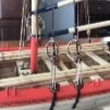
The channel for the chains and deadeyes was made from a quarter round cut from a lathed piece of Castello, notches milled and a very slight round up sanded in to conform to the hull line. Three bolts were installed.
The entry steps were milled using an end mill and a burr as shown. The bottom piece was glued on and the the length cut for the three steps and the ends filed. A tiny round up was necessary.
The break pumps were fashioned as described in TFFM. I still need to file home the brass ends and blacken.
I made the stand out of an old maple headboard and routed in the inlay which I got from Lee Valley.
What’s next and final? Basically a lot of cleaning up, varnishing, some trenailing, make the pedestals and mount the Hayling Hoy. Sorry, no real sequence to the pictures.
See you next time.
-
.jpg.d84ec4dad1d7791e855dca06210ab6f3.thumb.jpg.f45209242e851d4409eca1a09293165b.jpg) AnobiumPunctatum got a reaction from hollowneck in The Hayling Hoy 1760 by Seventynet - FINISHED - 1:48 scale - First fully framed model
AnobiumPunctatum got a reaction from hollowneck in The Hayling Hoy 1760 by Seventynet - FINISHED - 1:48 scale - First fully framed model
Really wonderful build.
-
AnobiumPunctatum reacted to dvm27 in Sloop Speedwell 1752 by Chuck - Ketch Rigged Sloop - POF - prototype build
The ships of the Cruizer class, of which Speedwell was one, were built in 1752-1754 to address the prevailing French and Austrian Wars. The Admiralty wanted fast, shallow draught ships that could carry out policing operations in the Channel and Foreland Stations and discourage French privateers and smugglers. Therefore, a variety of hull design and rig combinations was employed by the Admiralty to see which best fulfilled these requirements. Some were ketch rigged (Speedwell, Fly, Happy and Ranger) while others were snow rigged (Wolf and Cruiser). All this experimentation eventually led to a refinement wherein Cruiser was given a mizzen mast (1753) and ship rigged. This proved to be so successful that the ketch rigged sloops fell out of favor as the ship rigged sloop became prevalent. With the advent of the brig-of-war later in the century the snow rig once again gained popularity.
(From Building Plank on Frame Ship Models, Ron McCarthy. Naval Institute Press)
-
 AnobiumPunctatum got a reaction from FrankWouts in Sloop Speedwell 1752 by Chuck - Ketch Rigged Sloop - POF - prototype build
Unlike building guns, I find building frames meditative and relaxing. It's looking really good.
-
AnobiumPunctatum got a reaction from mtaylor in Sloop Speedwell 1752 by Chuck - Ketch Rigged Sloop - POF - prototype build
Unlike building guns, I find building frames meditative and relaxing. It's looking really good.
-
 AnobiumPunctatum got a reaction from Jack12477 in Sloop Speedwell 1752 by Chuck - Ketch Rigged Sloop - POF - prototype build
Unlike building guns, I find building frames meditative and relaxing. It's looking really good.
-
 AnobiumPunctatum got a reaction from Stuntflyer in Sloop Speedwell 1752 by Chuck - Ketch Rigged Sloop - POF - prototype build
Unlike building guns, I find building frames meditative and relaxing. It's looking really good.
-
 AnobiumPunctatum got a reaction from Seventynet in Sloop Speedwell 1752 by Chuck - Ketch Rigged Sloop - POF - prototype build
Unlike building guns, I find building frames meditative and relaxing. It's looking really good.
-
AnobiumPunctatum reacted to Chuck in Sloop Speedwell 1752 by Chuck - Ketch Rigged Sloop - POF - prototype build
The "SHORT SQUARE FRAMES".....
Basically these are built the same way as the taller square frames. They just dont extend all the way to the "jig" top that helps position the tall frames. These are the frames that fall where a gun port or sweep port are located. The "short frame" 2a is shown below. It does have a cross beam of sorts. This is used to help stabilize it and give it the correct shape. Notice how it is glued onto the bottom of little square protrusions on the inboard side of the frame. All of the short frames will have this cross piece. It will be removed after we plank the exterior of the hull much later in the project. You can build these as shown just like the other frames. Just make sure the stepped futtocks appear on the correct side of the frame when you glue them onto the keel.
NOTE the blocks for the sweep port labelled 2a. These are made by gluing two laser cut layers together. Glue them together so the etched reference letters face each other. Dont glue these onto the frames yet. Just keep them ready to go once you glue the short frame onto the keel first.
Dont forget to finalize the chocks by shaving off half of it....and when you glue them onto the keel make sure the "step" is facing the correct way....either fore or aft based on the plans.
If you recall, we installed a bunch of the tall frames earlier. This left a bunch of open spots where the shorter frames will be installed.
In this photo you can see a coupe of short frames I completed on the forward side so far. One has a sweep port and another has the lower gun port sill. There is another short frame which has been glued into position. It is frame 2a shown earlier. It was glued into the final spot I had ready for it between the two tall frames. Sitting on the top of the model you can see the two sweep port pieces which I will add next. I have already dry fit them in position. I had to sand a little off both sides to make it fit really nice without spreading the two frames apart on either side of it.
You will notice some pencil lines that I drew on both sides of the sweep port blanks. While they were being test fit, I traced the shape of the frames on both sides of it so I have a reference.
It makes sense to remove your test fitting of these and sand them close to those lines now before you glue them in position. It will save a lot of sanding when it comes time to fair the hull later. You dont have to get it perfect but try and chisel or sand these close to there finished shapes. You can see my pre shaped sweep port block for the starboard side.
Once sanded...I glued them in position permanently. Be careful to check your framing plan. Make sure you have these oriented correctly and dont flip them. You want your sweep ports in the correct position after all. Use the provided templates to make sure all of the gun ports and sweep ports are in the correct position..at the correct height and spaced properly.
These templates will be provided on the plans. This in combination with other means of measurement will really help ensure that your ports all end up where they are supposed to. The top of the template aligns with the sheer. The bottom of the template actually aligns with the top edge of the wales. The heights are most important for the ports and dont go nuts if your openings are a 1/64" to the left or right. It will all work out in the end. You can always fix slight issues before you start planking if you have to do some shifting. But I highly recommend that you use this template from the start of your framing to check the port positions as you progress. If you do this before you glue the actual sweep port fillers into position permanently (and the gun port sills), you can adjust them at that time to ensure the opening are in the correct spots. Then after you get them to match the template, glue them in permanently. Using the template is really the key to successfully and easily taking the guess-work out of positioning the ports.
NOTE: With any POF project there is a lot going on and a lot of parts. It is inevitable that some frames may not end up where you want them exactly. Thats OK and certainly it happened to me. You may get a slight bend in your frame etc. Your wood thickness might be a little over or under with your frames. Maybe a frame isnt perfectly perpendicular to the keel after it settles once glued in. Creep can be an issue after 20 frames etc. But regardless of where you frames end up you can easily manipulate the sweep port fillers and sills using the templates to get them exactly where you want them. As you can see the framing looks perfect to the naked eye but I can assure you they are not...the template is your salvation!!! The photo below shows all of the square frames complete with a template I used to ensure all of the ports are positioned correctly.
I did use my steel squares to line all of this stuff up as well. I used the square as a height gauge to make sure the sweep port was the correct height off of the build board. I have yet to do the port side and this will be done soon. This is where the model stands at the moment. Things will slow down now as I try and repeat this process until all of the square frames have been completed. There are over 40 square frames.
Resist the urge to incrementally fair the hull until you have quite a few frames glued into position. In fact it is best to wait until they are all in position but I do realize it is hard to resist. I have lightly sanded the exterior a bit but I am careful not to over do it. I dont want to screw up the correct shape for the hull which is tough to see with only a few frames on the keel like this.
When there is a lower gun port sill instead of a sweep port block, they are handled in the exact same way. They come in two layers as well....follow the same procedure.
-
-
AnobiumPunctatum reacted to shipman in Varyag 1901 by Valeriy V - FINISHED - scale 1:75 - Russian Cruiser
My heart is warmed to see your latest, fabulous update, which tells us you're ok.
-
AnobiumPunctatum reacted to Valeriy V in Varyag 1901 by Valeriy V - FINISHED - scale 1:75 - Russian Cruiser
Thank you all for your likes and comments. I am glad that my work is of interest and may be useful to someone.
Group photo of guns.
-
AnobiumPunctatum reacted to JpR62 in HM Cutter Cheerful 1806 by JpR62 - 1:48 scale
For both sides (port and starboard), I proceed in the same way. I first make a card template by directly taking its shape from the model and use this cardboard template to reproduce the pieces to be cut on the cedar sheet (leaving a safety margin of 1 mm on each side).
I decided to reproduce the cap rail in 2 segments, the joint being placed between gun ports 3 and 4.
The 4 segments are then ebonized and glued. I then protect (on both sides of the bulwarks: outside and inside) the planking with masking tape and sand to be level. Despite the masking tape, some paint was scratched and will need to be touched up.
The fancy moldings are prepared, ebonized and glued to the outer side of the cap rail. I protect the first part of the cap rail (the 5/32" wide strip) with masking tape so that I can fill the small gaps between the cap rail and the molding without getting too dirty.
This will also allow a faster sanding...
On the picture below, the cap rail on the port side is already sanded while the wood filler (tinted black) has been applied and dried on the starboard side
The cap rail is then painted black.
I'll be able to concentrate on the last details (drilling the hawse holes and bowsprit) and start the deck planking.
And always as much fun.
-
AnobiumPunctatum reacted to mbp521 in USS Cairo 1862 by MPB521 – FINISHED - Scale 1:48 - American Civil War Ironclad - First Scratch Build
Hello again everyone, I'm ready with another Cairo update.
Over the past few weeks I have been focusing on some of the detail work. I started off with the anchor buoy. This was one of the artifacts that was recovered during the salvage and sits on display in the Cairo museum.
On my first attempt to make this I was going to try and make it from card stock shaped into two cones with a disk in the middle to form the flanges where the two halves met. I tried several times but just couldn't get the shape right. Since I wasn't sure of how this method was going to work, I didn't take any pictures. So, on my next attempt I tried using Milliput, getting the basic cone shape and then finishing it off on the lathe. Here are the two halves on this try.
I drilled the center holes for the toothpick to align the halves together, but again I just couldn't get the shape I was looking for. For some reason the centerline wouldn't fall in the right place and I was having difficulties trying to figure out how I was going to make the center flange. So I ended up scrapping this version as well.
On my final attempt I decided to go with some copper sheeting and the same method I originally used with the card stock. I scrounged up a few small scrap pieces in my scrap bin that I had left over from the chimney flanges (I throw nothing away) that worked perfectly. I managed to have enough to make the two halves and the center flange.
Here are the two halves glued to the center flange.
I fit a small piece of styrene rod through the middle to provide a mounting place for the eyebolts, then drilled a tiny hole in each end to receive the eyebolts.
The eyebolts were then glued in place.
and finally the whole assembly painted up.
Before I can place these on the boat, I'll need to research how these were rigged to the anchor. I have a sneaky feeling that this is going to be a task to find info on these, but I'm going to see what I can turn up.
Next it was on to installing the bow guard. Nothing too complex here, I had made this a while back and just needed to put it on. I left out a couple of the rivets to use a mounting points to give the guard a little more of a secure grip on the keel, than just gluing on.
Then I moved on to the Hurricane Deck canopy. There are numerous contemporary photos of the Cairo's sister ships that show almost the entire Hurricane Deck covered with canopies, but the only photo of the Cairo has just one canopy over the boiler skylight. It is not known if the Cairo had more than this when she went down so I just went with what she had in the photo. Besides, too many canopies would hide a lot of the deck details.
Attempt 1: I took a small piece of muslin and cut it to shape and size, but I was having a hard time keeping the edges from fraying. So I took some CA and ran it along the edges of the material to keep the strands in place. Definitely didn't like that look.
The muslin had the texture that I was looking for so I stuck with that material. On my second attempt, I cut the canopy shape out, bit this time I soaked the whole thing in diluted clear Elmer's glue and let that dry. For added details, decided to put a ridge vent in the canopy since I figured that these were made up similarly to the field tents used on land by the Army.
Then I went in and added the grommets for additional detail and used those as a way to cover the canopy guy ropes.
Then the whole thing was installed along the center beam and the guys attached to the stanchions.
Making up some of the rope coils for the canopy guys on the stanchions.
Next, I wanted to finish up on the aft skylights and get the door installed. So it was back to borrowing the Admirals Cricut again to cut out the window frames. I built these up exactly the way I did the others and mounted the Port side open and the Starboard side closed.
Next up, it was on to the forward and aft hand ropes for the casement ladders.
Completed forward ropes.
Completed aft ropes. Initially the ropes didn't sit right, they had a bit too much sag to them. So I ended up running a bead of CA along each one to stiffen it up and hold its shape. I think the overall look came out quite nicely.
Next was the installation of the long hawser. This was probably the one that Commander Selfridge ordered tied to a tree on the Yazoo River bank when he had the ship ran aground shortly after the torpedoes blew the hole in Cairo's Port Bow. This hawser held long enough for everyone to abandon ship, before the tree was pulled from its rooting and the ship slipped beneath the surface.
Then it was on to another one of the more tedious parts of the build. The chimney guys. The Cairo display has one set of these installed on the "Ghosted" chimneys with the rest being just steel cable. The original guys were actually iron rods and links (rings) that had a threaded loops on each end to adjust the tension. These guys can be made out in the old Cairo photograph, although some of the photos of her sister ships look more like they have cables or ropes holding the chimneys. I went ahead and built it like the photograph and because there were some of these recovered from the salvage.
These are some of the original guys on the Cairo display.
I started with some 24ga wire to make the rods.
And bent them to shape as well as the rings.
Tedious work. I had to make up 80 of the rods and rings along with 20 hooks for the anchor points on the chimney and stanchions.
Once they were made to length, I heated them up red hot with my torch to give them that blued steel look. This color works nicely with the casement color.
All guys in place and blued. I took a lot of pictures of these, I guess you could say that I was somewhat proud of how they turned out.
After making up all of those links, I needed a break. So it was time to do a little cleaning of the work bench before moving on to the next project.
So after a good bench cleaning I moved on to another tedious project, installation of the boat davits. Normally this wouldn't be too big of an issue, except the slanted casements of the ships make the task a bit more challenging when it comes to getting the davits all lined up properly. And since one of the davits on each side sits on top of the armor plating, it makes it that much more difficult to get the height and alignment correct.
I started with the Port aft davits first. This wasn't too terribly difficult. I used some double sided tape to temp install the mounts then slowly nibbled away at the bottom of each davit until I got the proper height and location.
Test fitting the boats to make sure there is enough clearance.
Once the aft davits were installed, that was where I ran into an unforeseen issue. When I first started this build I had not planned on doing a whole lot of internal details since it was going to be a static model with all sides enclosed. As I built the details on the gun deck I decided that I wanted to show off some of these details and decided to make the Port side a cutaway. Well poor planning on my part didn't take into consideration that one of the davits was going to fall inside the cutaway. So when I built the cutaway I just mounted a small scrap of wood between the casement frames and figured I would just mount the davit base on that. Well, I didn't like that look, so change of plans.
This is the area where the davit base will go. What I decided to do was to build up the armor plating in the area and mount the davit properly.
So I pulled off the armor plating to make sure the panels lined up the way they were supposed to.
Then I offset every other one to cover the area for the base mount.
Gave everything a fresh coat of paint and some rivets.
Then it was on to mounting the forward Port davits.
Now it was time to rig the boats and temp install them. Started of with stropping the blocks.
Then running the ropes through them.
One boat in place. I wanted to show this boat as in the process of being launched, due to it's location above the cutaway. Placing it in it's stowed position would have blocked part of the view in the cutaway and I wanted to give the build a bit of action, not just a static model.
Both Port boats in place. I need to find a way to stiffen the ropes so that they look like they have a load on them. The boats just aren't heavy enough to keep the line taught. I think a little diluted Elmer's will work. I also think it will also help keep the boats from swinging around too much when I move it.
Now it's on to installing the Starboard davits. Pretty much the same as the Port side.
Now with the rigging all in place I need to find out how they would have stowed the tackle on the covered boats since my Starboard boats have tarps over them and the lift rings are under the tarp. More research.
Finally, she was getting a little dusty so I decided to take her outside to the barn and blow some of the dust off of her. It was such a pretty day out, I figured I'd snap a few pictures of her in natural lighting while I was out there.
She's getting pretty close to being done. Perhaps a couple of more months and I will call it complete. Most of that depends on how much more research I need to do to get info on the anchor buoy, boat rig and rudder linkage. There is no rush, I'd like to finish by December 12th to celebrate the 160th anniversary of her sinking, but if I don't make it, so be it.
I thank you all for the kind words, comments and likes, as well as taking the time to stop by and view my build. Until the next update, everyone stay safe and healthy.
-Brian
-
AnobiumPunctatum reacted to Trussben in HMS Pegasus 1776 by Trussben - 1:48 - Swan-class sloop based on TFFM
I finished blending in the Rudderhead framing to the stern and then started mocking up the upper counter and stern light layout - still needs tweaking.
-
AnobiumPunctatum got a reaction from FrankWouts in Sloop Speedwell 1752 by Chuck - Ketch Rigged Sloop - POF - prototype build
It looks excellent. You make it really hard for me to stay true to my resolutions.