


DaveBaxt
-
Posts
1,303 -
Joined
-
Last visited
Content Type
Profiles
Forums
Gallery
Events
Posts posted by DaveBaxt
-
-
Sorry I have not replied to this sooner. But a thank you to all people who have particicipated in this discussion and also something which I would like to carry out a few experiments of my own to see what looks best from a distance. I have already done some test of just painting with an airbrush a mixture of weathered copper ( brown) and verdegris which I think was quite pleasing. However I am still not totally convinced this is the best way forward. Another thing which I am unsure is whether or not to seal the wood prior to gluing any copper tape or plates and have considered using shellac but wonder if this is necessary .
-
-
I am considering creating a patinad look to copper plates and have seen excellent results using miracle grow( plant ferilizer) and red wine vineger. However once the required patina look is achieved what is available to seal this to prevent further corrosion or change in colour which will not react with the patina. I have seen available coatings such as Everbrite or Simple coat but don,t think these are available in the uk. So what is? otherwise perhaps shellac or polyurathane can be used but unsure if I want anything with a gloss or semi gloss finish.I came across this product . Unsure as it is very expensive. https://www.goldleafsupplies.co.uk/metal-effects-permacoat-extreme-473ml-4318/
What do you guys think?
Thank you best regards Dave
-
I am sure you are correct Allan and I do not doubt you. However I feel that for this model it is just a fraction too late so will continue as I have . However it is something that I will try and remember for my next model and plan within good timing to achieve exactly that. Thank you once again for your input it is always apreciated.Best rergards Dave
-
Thank you Allan for your remarks regarding the main wale. Unfortunately I did not. I was unaware that the were thiiner at the bow as are the other planking and I just followed the instructions.I read through Peter Goodwins book on the subject of the main wale prior to adding the wale to my model and although he mentions the black strake being thinner , I did not see the anthing regarding the wale planks being thinner at the bow. It was not my intention to cut another rabbet for the second planking, especially as it is only 0.7mm thick. However please let me know where I can find out about the thinning of planks for future reference and building.
-
Great work on those rat lines Dave and good to see you managed to secure both ends and I think by your drawings you can see both methods of using a clove hitch and hopefully that has worked out well for you.. I found that tying the ratlines above the futtock stave particularly difficult and can see you have done an excellent job of this. Once again your workmanship is a credit to you.
-
Sorry for the delay Allan in replying to your query regarding the 84" dimension and ses I did mean the 84" dimension. I have at least got time and enough measurements to study this further with calculator in hand ( do people even still use these) in between carrying out the joys of planking such a large hull, at least for my previous standard compared to that of the Bounty and Endeavour. Especially as I will be changing from boxwood (seen) to walnut (covered). Another first for me. I am considering 120mm length planks to use as little waste as possible with the boxwood and yet be realistically long enough for 1/64 scale. In the past I have used full length strips without any breaks and usually got two lengths out of each strip. With this hull without any breaks would mean quite a lot of wastage.
Some more boxwood will hopefully arrive tomorrow from https://www.originalmarquetry.co.uk/?s=boxwood&post_type=product and I now have a number of different. My approach will be to complete under the wale down to the keel first then once I have hopefully mastered the technique then move onto above the wale and around the gun ports which may or nit be problamatic. After fitting of the 0.5mm thick black strake followed by 1mm x 3mm walnut for the rest of the wale and the sanded and sealed with shelac, followed by Adrimalty ( Caldercraft ) dull black acrylic watered down with a few drops of thinners and improver using an airbrush once again.
Y
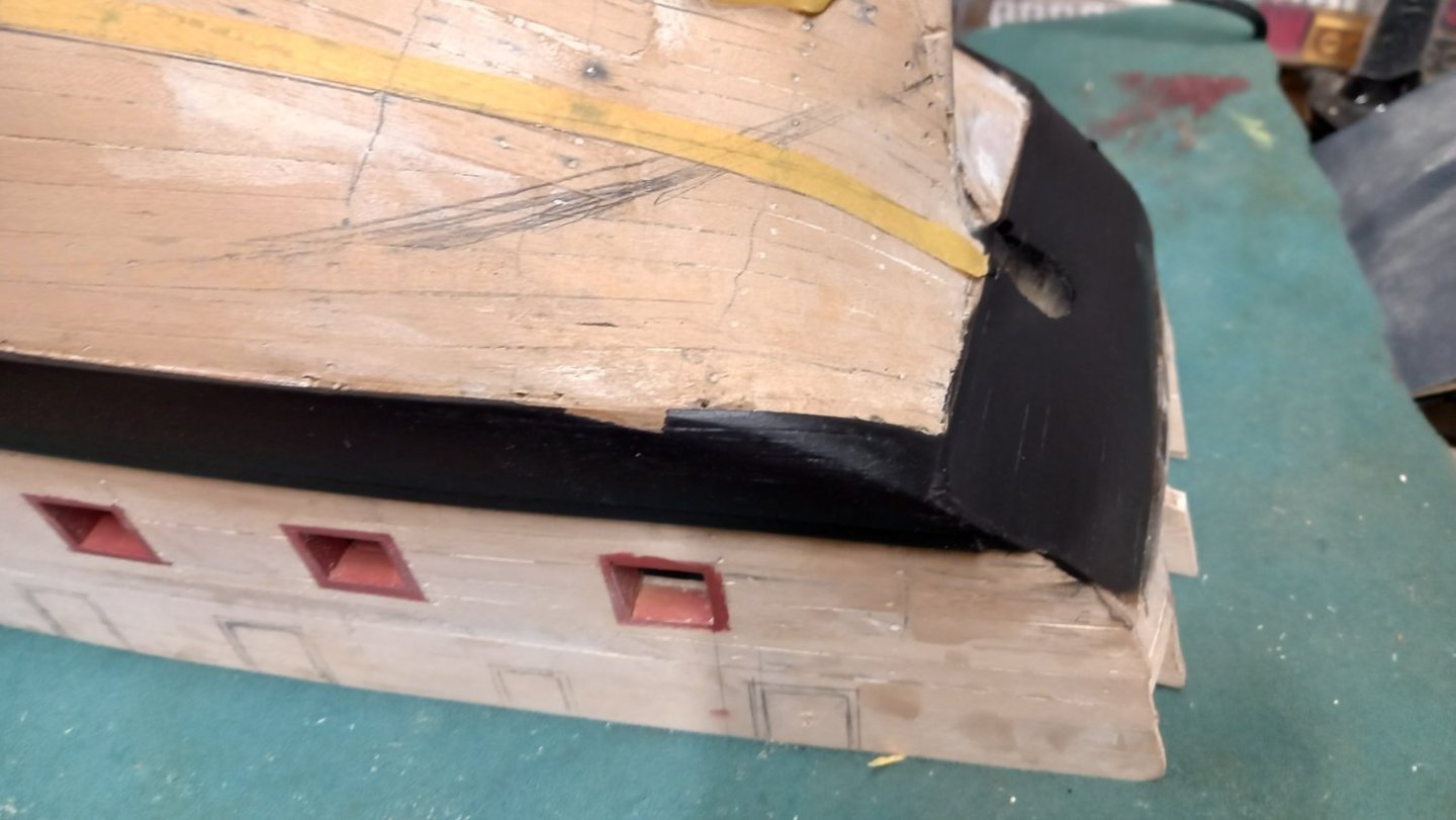
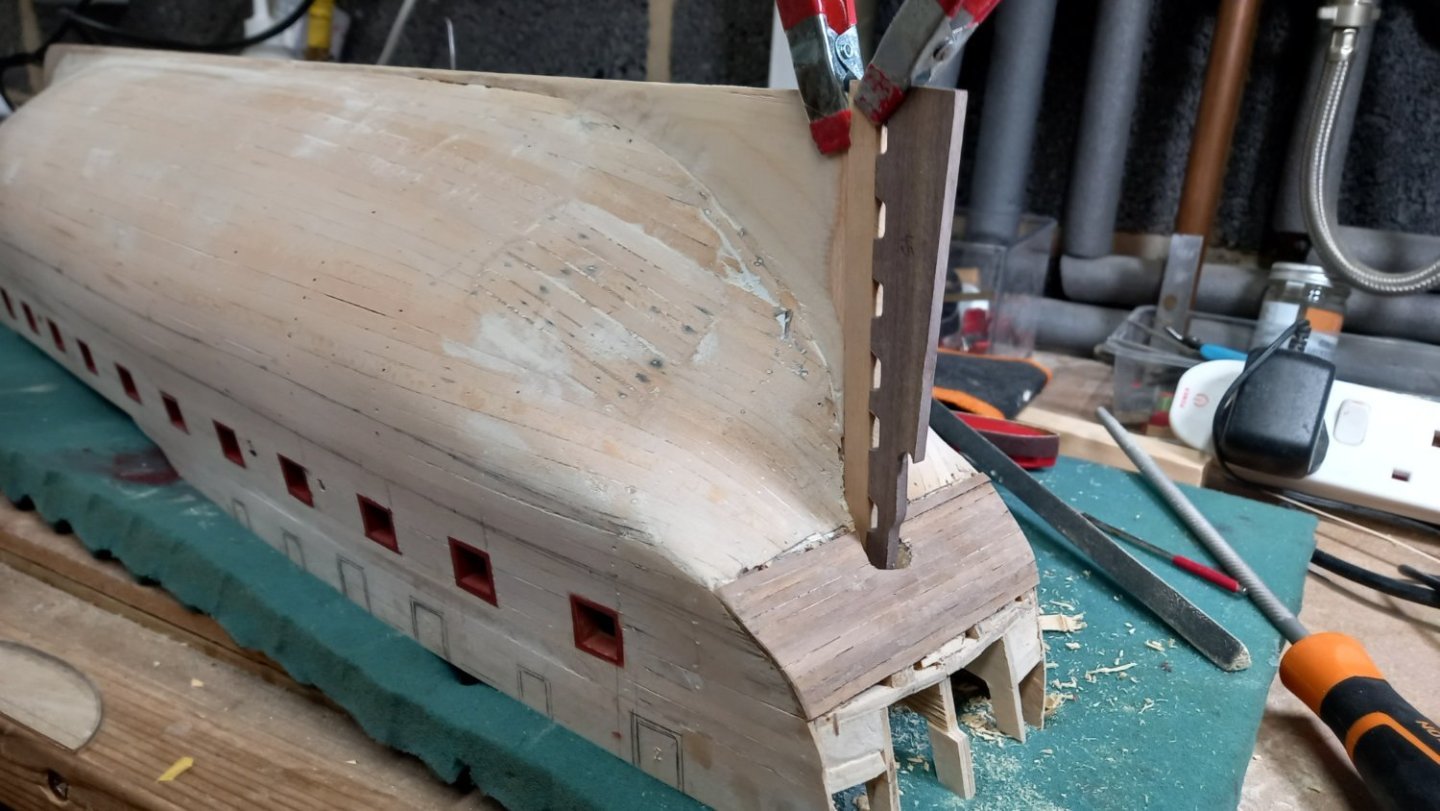
You can see from the above photos that I had a slight accident with the stem and broke off the top half, so I will need to glue this back on at some stage but might as well wait until I have finished planking and secured the hole for the Bowsprit mast before doing so. On removing the masking tape I also realized I had missed a bit of black on the wales. There is always one. Oh well hopefully I can touch this up.
 Next up will be the second planking and hoping I can make a good job of this.
- Theodosius, dunnock, DavidEN and 1 other
-
 4
4
-
2 hours ago, allanyed said:
I scaled the drawing to 1:64 and get 17mm. IF the contemporary drawing is correct, it could be the kit got it wrong. I was curious to know what the AOTS book showed dimensionally so downloaded their drawing and compared. (Forgot I had that book 😕) There is a 10" difference between the AOTS and the drawing from 1774. Note that the widest part of the quarter gallery is the same on the original drawing and the AOTS drawing.
Allan
Sorry to be a pain Allan can you clarify what the 34" measurement is ie is it from the aft gun port to the fwid upper edge of the rudder or something else ? Once again thak you.Best regards Dave
-
Thank you again Allan for taking up your time and checking out these sizes for me and hopefully allow me double check. Your will to help is a credit to you.
The most worrying aspect of your sizes for me is the 43"measurement between the forward edge of the quarter gallery to the aft side of the stern post and after I have converted into metric( sorry but lost the knack of using imperial measurements many moons ago) and applied the 1:64 scale I am way out for some reason. I will revearse this on my model and also with the AOTS drawing and perhaps I can figure out why my maths is now so bad.
-
1 hour ago, allanyed said:
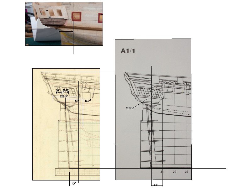
I got curious and inserted your photo into the drawing as well. The gun ports per the drawing should be 35.5" fore and aft. I sized your photo to match the gun port width of the drawing. Given that port dimension on your model is correct, the dimension I gave above of 128.5" looks to be closer to 144" on your model. The openings for the lights are 22" and the space between 17" compared to the 26" and 7" on the drawing. I am probably not making any sense, but maybe the below will help. I realize this is not accounting for the slight curve in the z axis, but should be pretty close IF the dimensions I am guessing at on the model photo are close. Sorry for the full size dimensions, but it is easier on the CAD drawing for me.
Allan

Than you Allan for clearing up those sizes for me and giving me something to work wth . I will give everything another check over and see if I can work out what the differences are, althoug I am not sure you can go from the gun port sizes as these are taken form the drawings supplied by the kit plans, which were pretty near the AOTS plans and think this is perhaps where the sizes were origonally taken.
-
Allan thank you for those sizes on your drawing but unsure what the 25.5 " measurement is for ? Perhaps when you get a chance, you could clear that up for me.Thank you once again. for your help I think I will need to start from scratch with these galleries and build them up from the bottom and add a few pieces at a time, as did DaveEN. I definately need to give this a bit more thought as I continue with the wales and second planking which could take me some time due to the transition areas between the Walnut and the boxwood, esppecially as they are different widths . Hopefully this can be achieved when spilling the planks foreward but still need to work this out at the aft end.
-
Thank you Jason and Allan for you help in the problems with the quarter galleries and wales , It seems to me that every time I deviate from the Caldercraft drawing and use other means there are consequences further down the line. As I wasn't happy with the quarter galleries where they meet with the top of the wales, I decided to check the position of the top of wales against the Caldercraft plans ( heights above the keel at each gun port) there are some discrepencees between this and the distance below each gun port taken from the AOTS book. It is my belief that as I altered the height of the gun ports to ensure that the Bloomfield cannon would be central in the gun port , I may have changed the position of the top plank of the wale, when taking measurements from the gun port. I therefore decided to use the measurement from the keel at each gun port from the Caldercraft plans instead of from the bottom of the gun ports ( measured from the AOTS Diana). Interestingy enough this has not altered the height of the wale of any significance at the stem and stern. For what it is worth I decided to remove the original first planks of the wale and re position them( using new ones) and taking the measurement from the keel and hopefully this will give the lines a better look.
Jason your idea of the quarter galleries in the kit being too big is definately worth exploring and may be the answer I have been looking for. Allen the problem with the counter is not that it bends too far as bending it further would move the quarter gallery further forward and then would end up too close to the last quarter deck gun port. If anything I thought about extendng the frame to move the stern counter further aft if anything but think that is a bit drastic. Allan I am pleased you posted those drawings as it does look like the supplied stern galleries are way too big. I will need to check these sizes with the AOTS book sizes as I am unsure how to take the sizes from RMG Diana and see where I am with this.
I would like to thank you guys again for your help and guidence as it is helping me a great deal. I would also like to thank everyone else for all the likes as this is encouraging me to keep going.
Here is what I hope is the final position of the wale . These are the 1mm walnut planks which sit under the final layer of planks. I will probably use walnut for the wale as this will be painted black.
- Knocklouder, AJohnson, DavidEN and 4 others
-
7
-
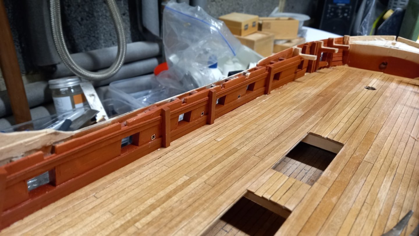
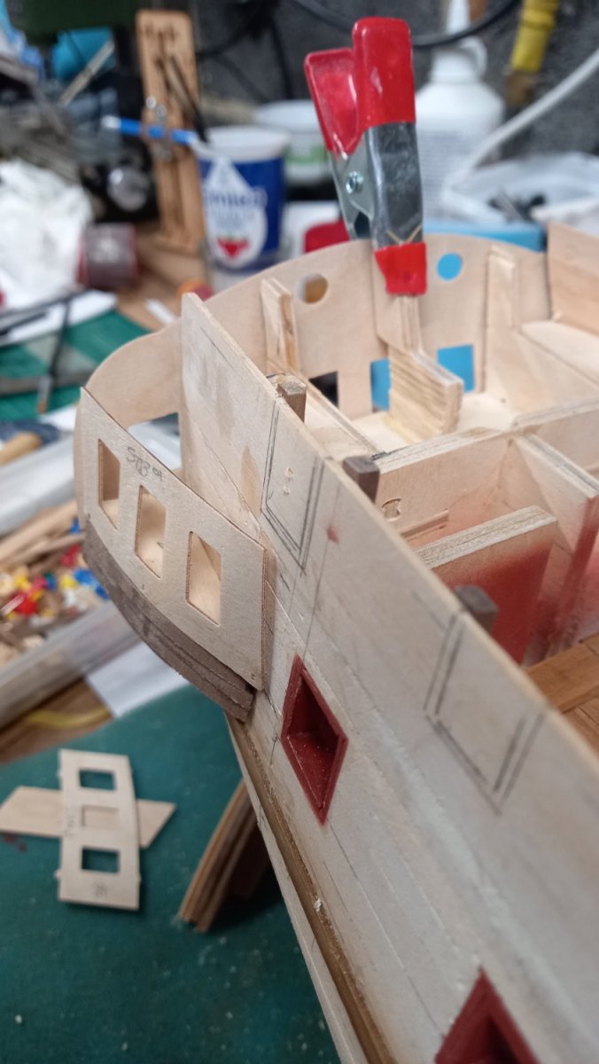
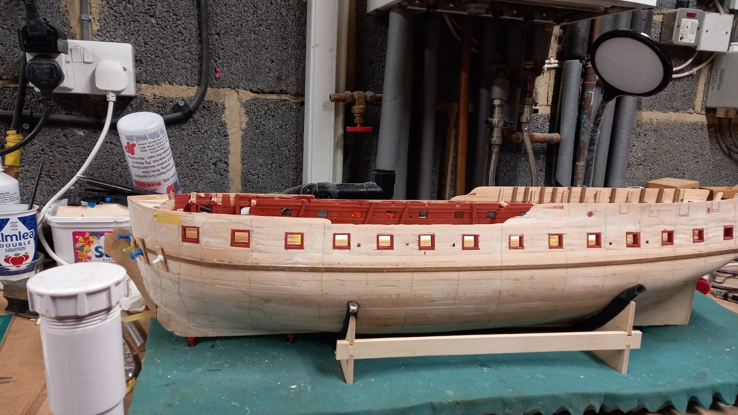
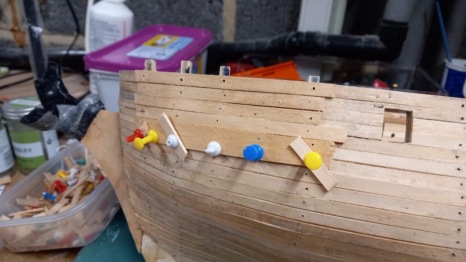
Before adding anymore planks to the wale I decided to make up a few of the parts for the quarter lights and see how they line up with the aft end and line up with the gun ports etc
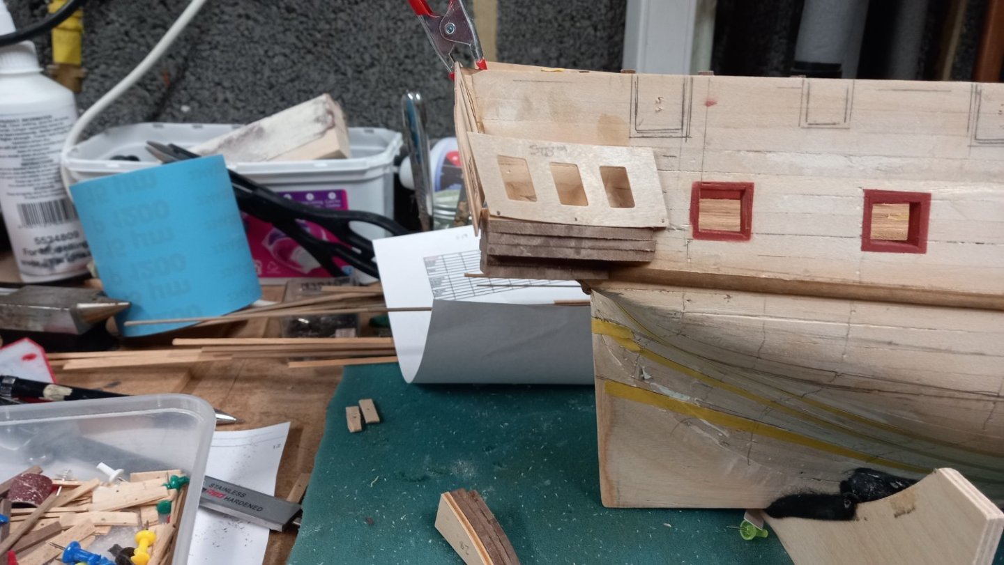

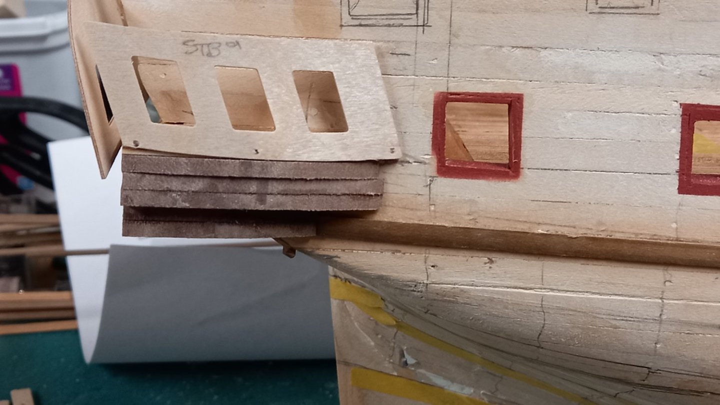 Although this is just a rough idea what goes where, something is not quite right. With the stern counter in what I think is the correct position, the windows just in line above the floor and the top of the counter lining up with the upper bulwarks . The quarter lights look to be too high but follow the line of the deck. In this position the whole thing appears to miss the upper and lower gun ports which is mainly what I am pleased about . Unfortunately there is a probllem with the bottom of the quarter light housing and it looks as though I will need to lower the stern end of the wale so that only the bottom cast fitting just rests on the wale. I think this is the correct position for it but could be wrong.
I still need to add a few parts to the quarter light housing but unsure what I have done wrong as I was fairly confident that the wale was in the correct position but will have to check again. Any ideas where I might be going wrong with this and thank you again for your help and patience. Best regards Dave
-
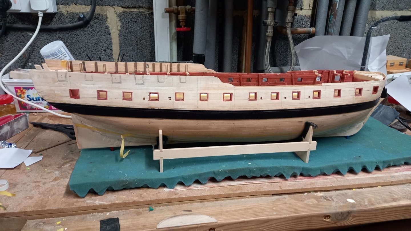
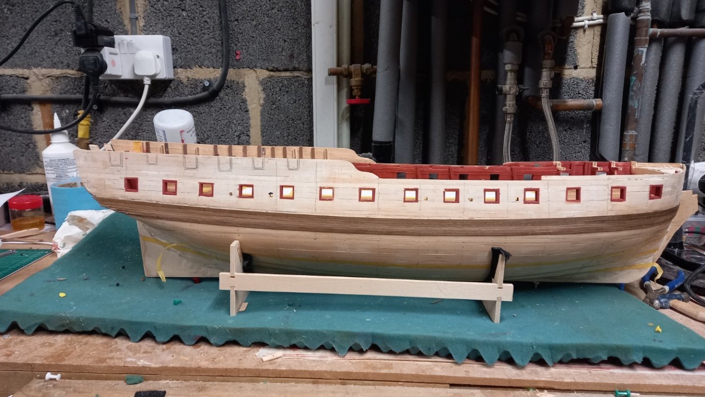
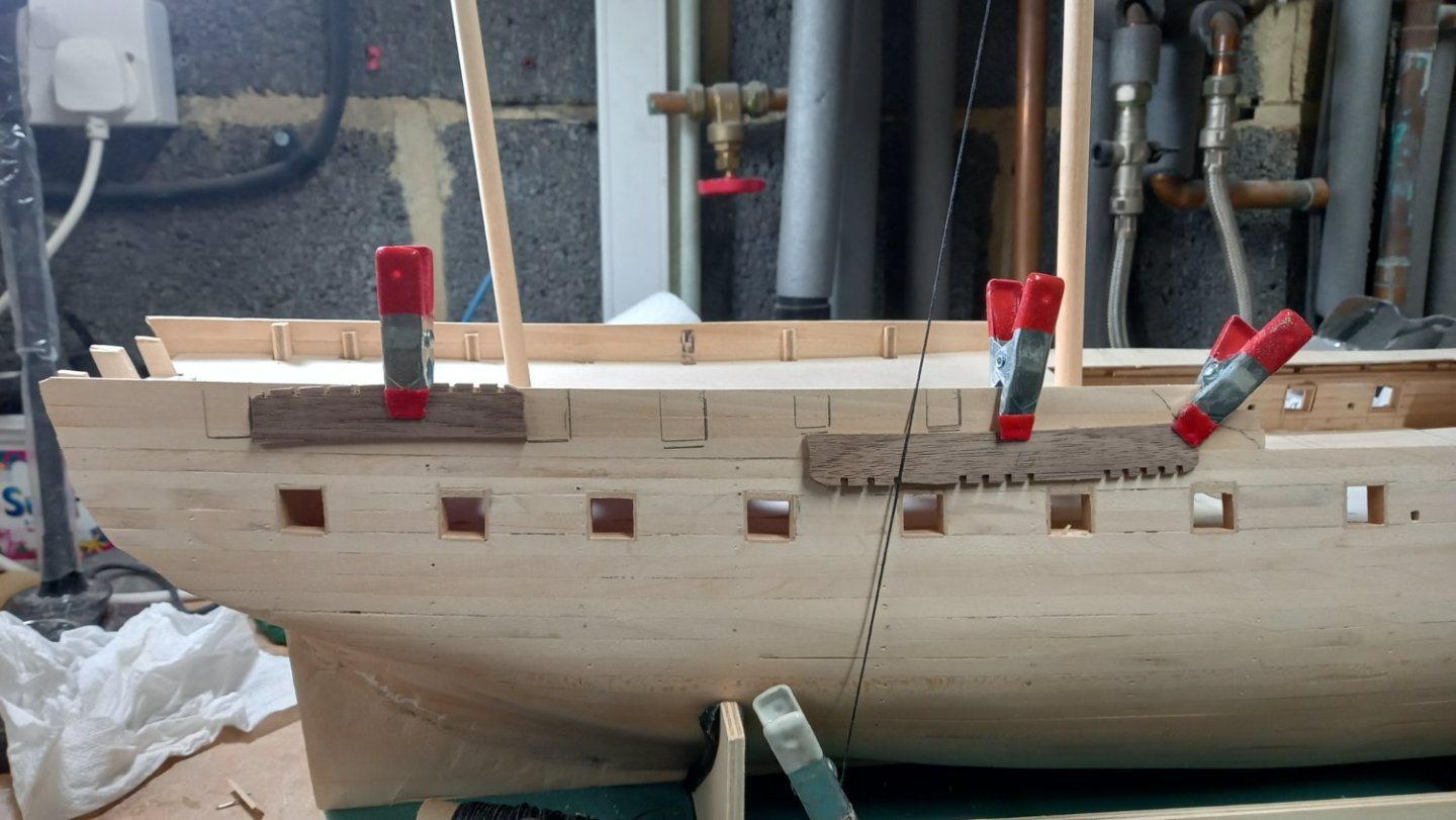
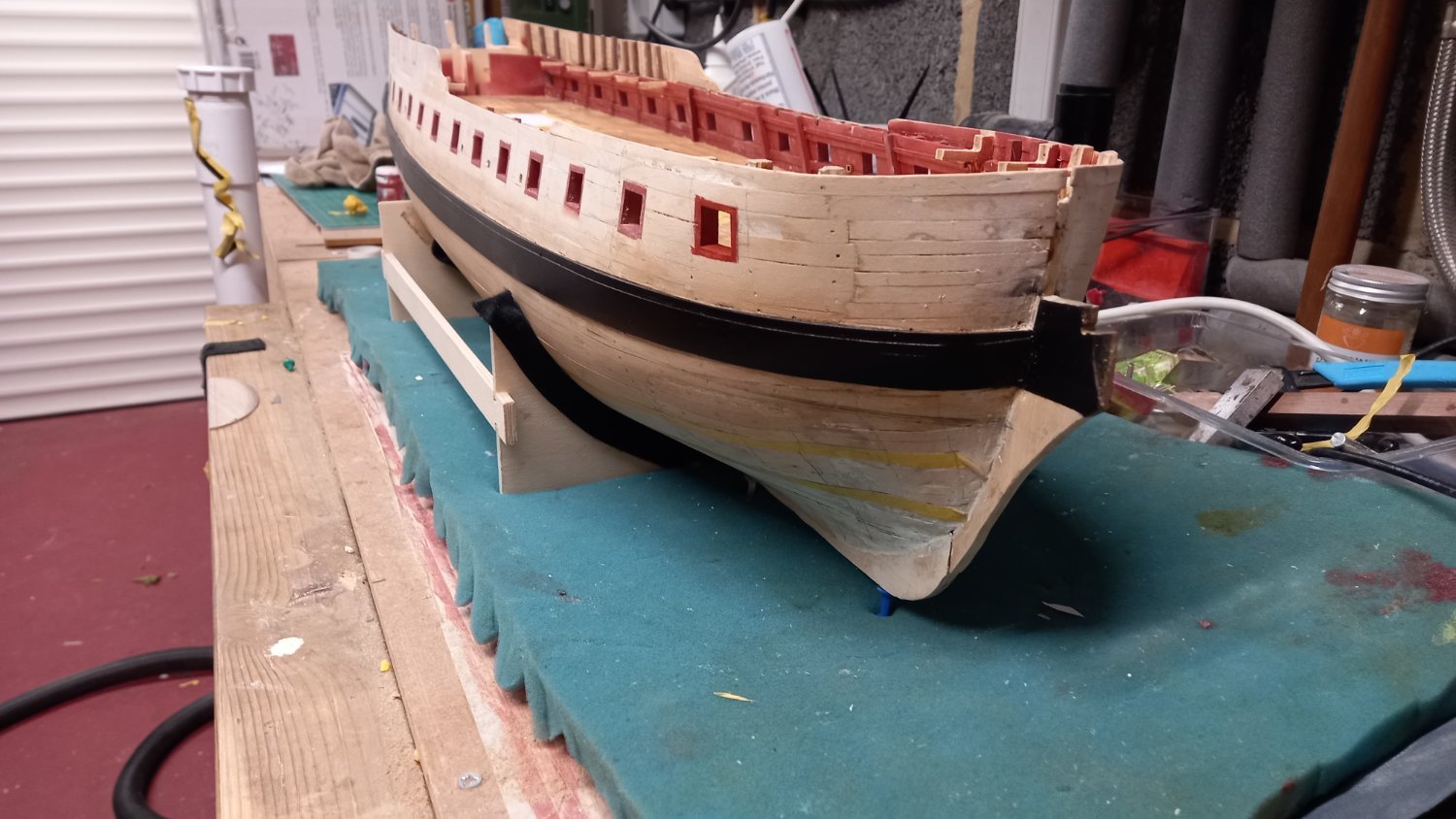
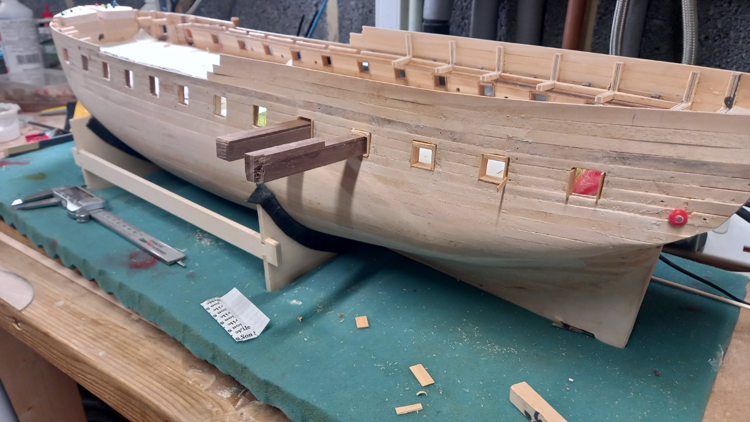
After one or two smaller jobs such filling the hull section below the counter with 1 x 3 mm walnut and then making the hole for the rudder post and rudder I have now moved onto the positioning of the top of the wale. For this I used the measurements from the AOTS book taken from below each gun port which turned out to be pretty close to the supplied drawings. I appreciate the importance of the position of the wale and after gluing into position the first plank of 1 x 4mm walnut I think it looks ok and compairing the distances between port and starboard wales from the keel it looks to be pretty close .
I also marked off the position of the quarter deck gun ports and fitted beams on the insides with 3 x 4 mm walnut. I also have made up some 12Lb cannon and 32 Lb cannonade to check the heights of these gun ports and look to be ok and hopefully there is some adjustment on the cannon so they will sit centrally in the gun ports.
Bb

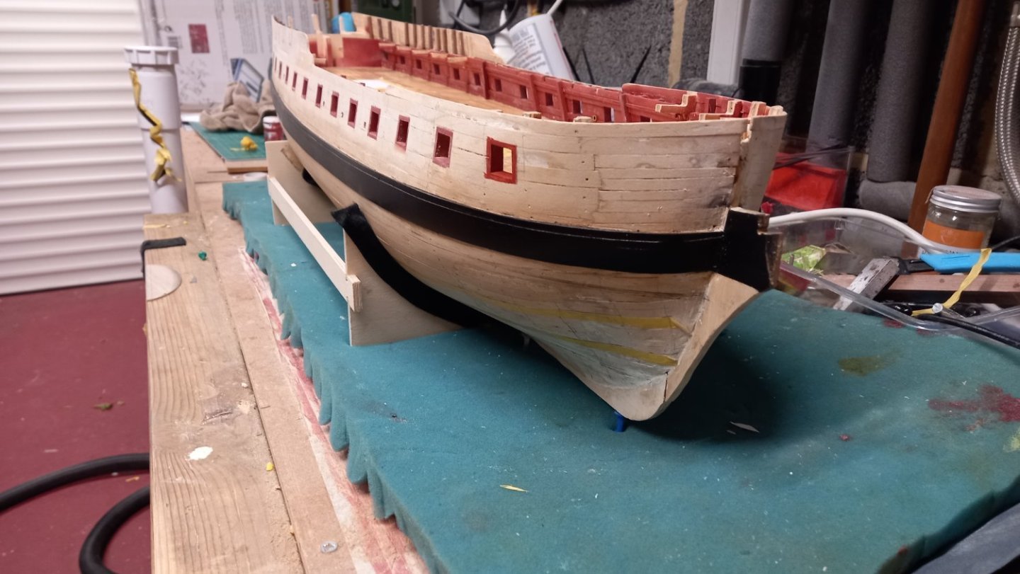
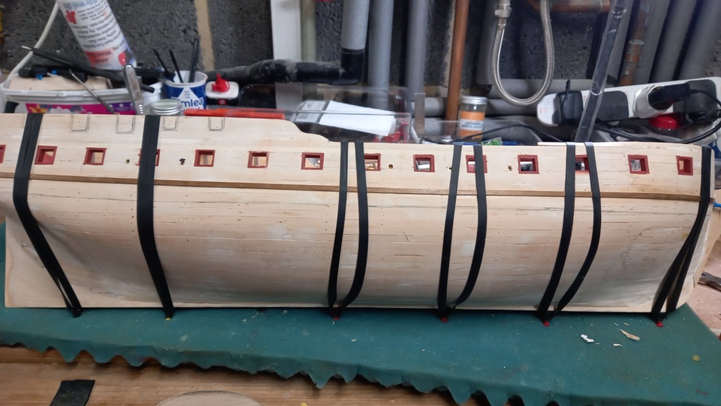
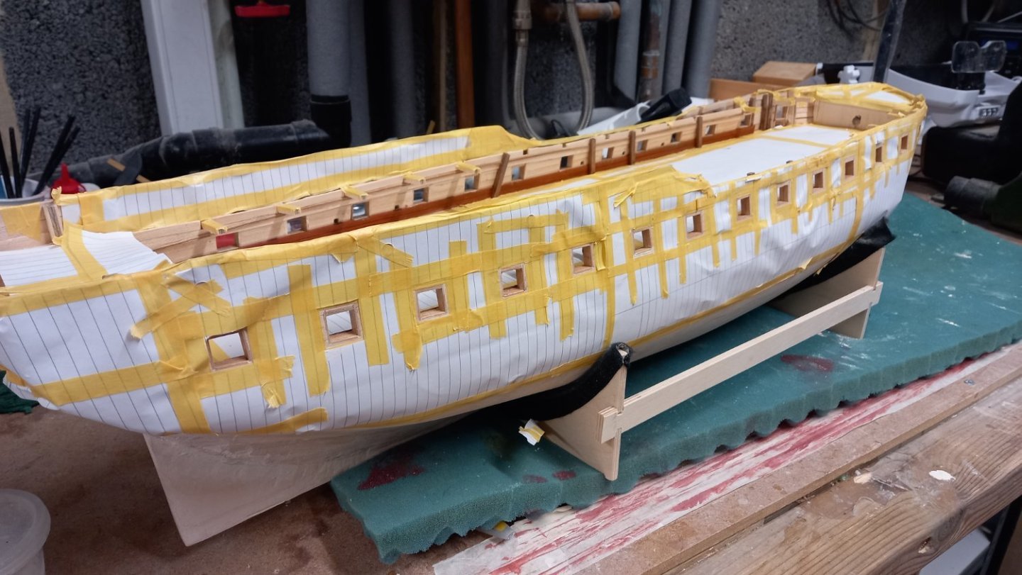
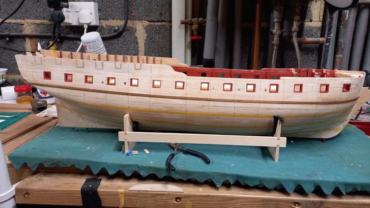
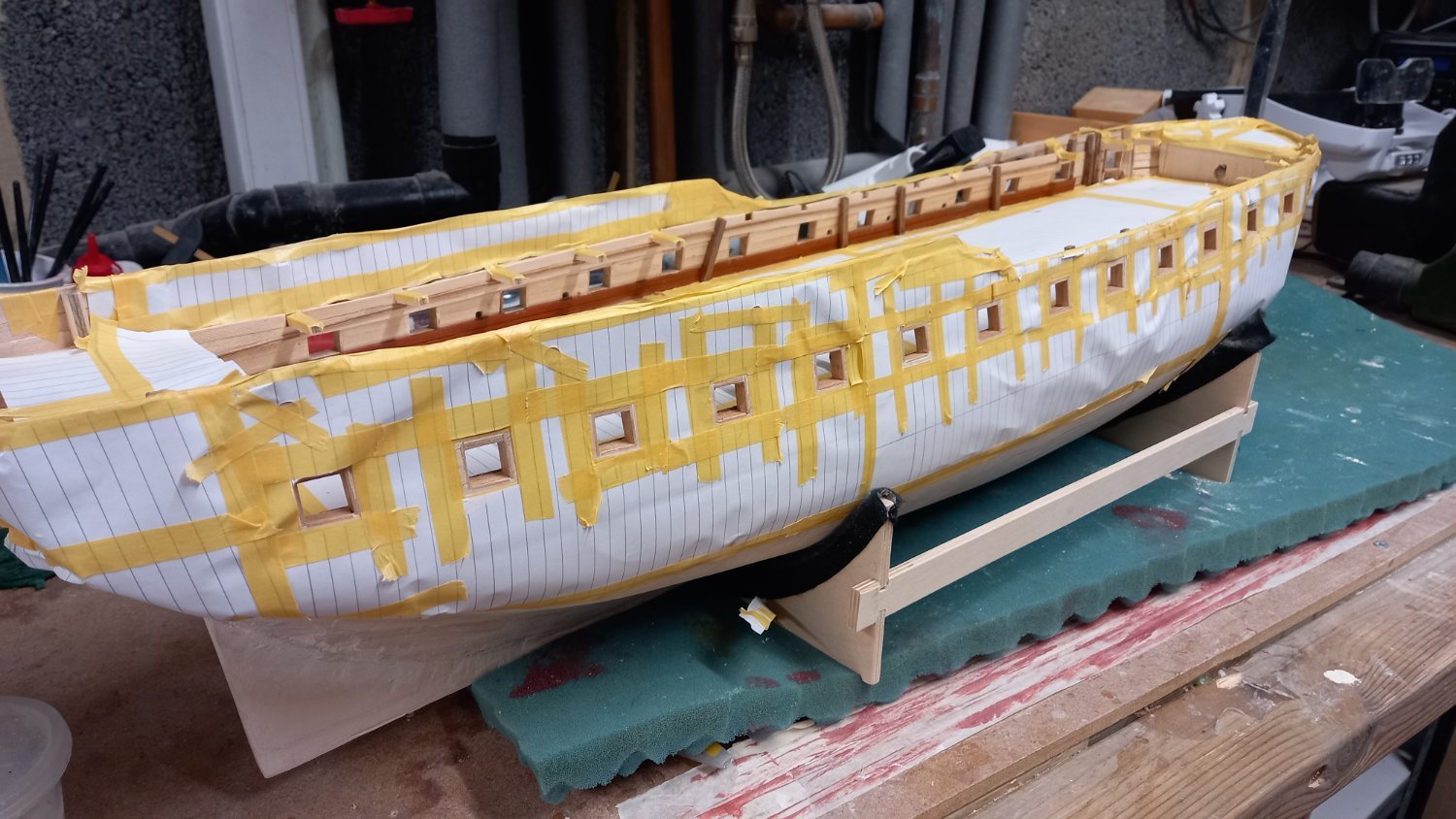
Before moving onto the second planking I still need to mark off the water line. I have already marked off the zones for planking with yellow masking tape. As yet I am unsure whether to lay the provided copper plates as the nails are way out of scale. However I do like the look of DavidEN patina looking plates but I have continued to consider painting something similar on the bottom instead. I therefore need to make the second planking as neat as I can below the water line. I need the practice too.
As I have also decided to use boxwood from the waterline up for the second planking I can see there is quite a few planks to change between boxwood and walnut which is a minimum of 0.3mm so could be a lot of sanding the walnut. At the moment |I am unsure how far above the water line the copper plates are fitted to allow for trim, weather etc so still need to do some research on this. As this is the first time I have used different types of wood on the hull I am a little concerned about this transition between the 0.7 mm and 1mm to 1.25mm thickness of walnut and how to get a nice smooth transition. At first I thought it was simply a case of changing from boxwood to walnut at the wale and continuing with walnut below the wale. If not I will probably need quite a bit more boxwood. Think I will probably go for some different sizes smaller than 6 mm wide to hopefully make those planks easy to lay around those tight curves at the stern and less sanding as they are only 0.7mm thick.
-
-
17 minutes ago, AJohnson said:
Looking good Dave, you are making really good progress! 👍
Thank you Andrew. As the Weather is now beginning to really warm up and holidays are starting to come around I am mostly wotking in the mornings but unlike last summer I have not taken a complete break as yet. Once things cool down again I am hoping to get back to rigging the Endeavour and perhaps just work on the Diana occationally until the Endeavour is finished. Best laid plans and all that................
-
Preparation for second planking.
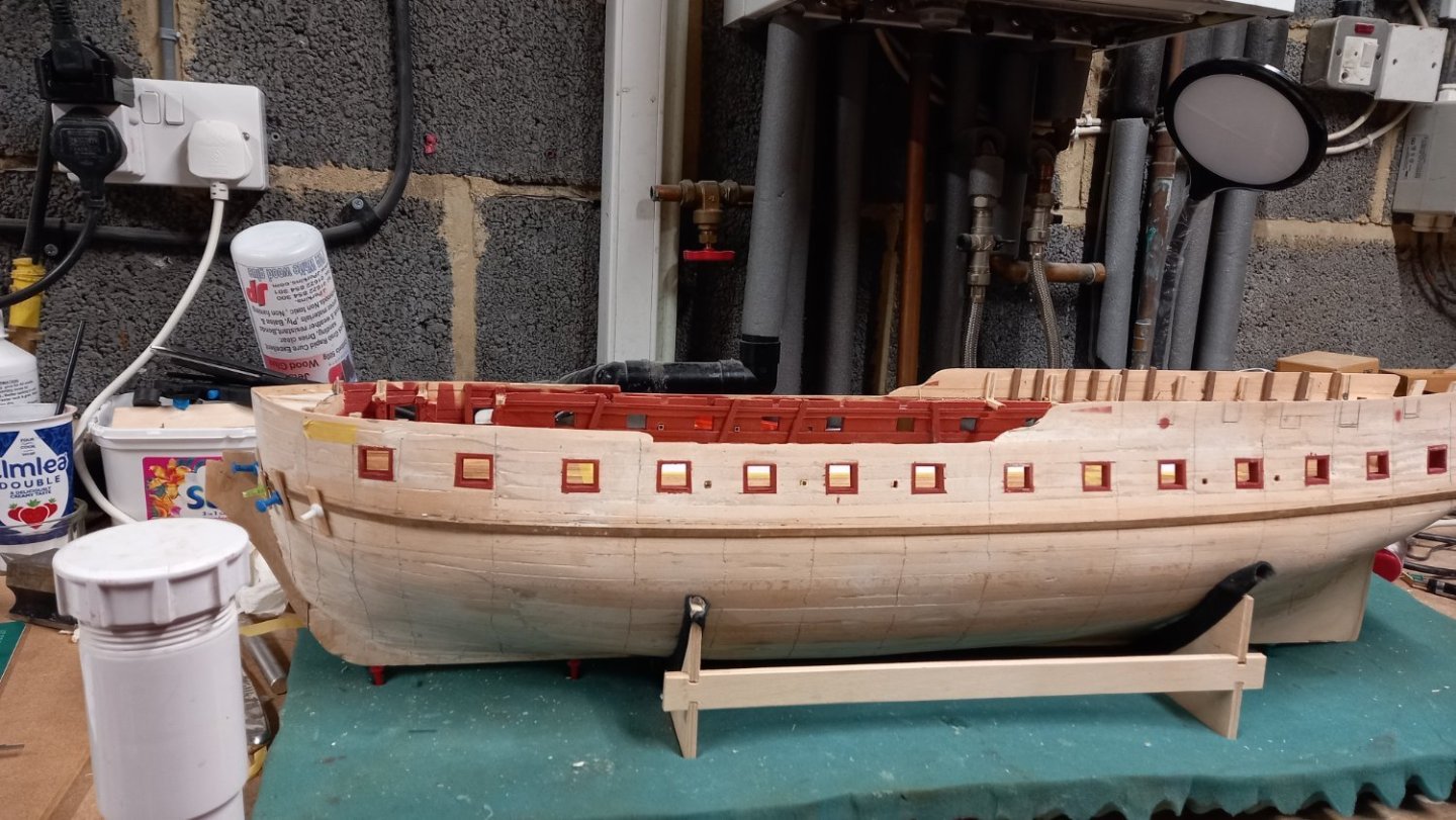
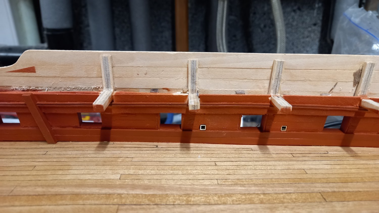
It would appear now is a good time to paint the inner bulwarks and gun port linings prior to fitting the second planking. However before doing so it was evident that the skidbeam clamps were too big for the 4 x4 mm riders to be fitted over the top of these so I ended up removing them and making smaller ones out of 2 x 1mm. I think this was an improvement. I made the riders on my Proxxon milling machine but was not entirely happy with these.
I gave the inside of the bulwarks a coat of shellac before painting with Caldercraft red orchre which looks very authentic for this period but could be wrong as I am no expert. I also tried my hand at air brushing for the first time as I did not want to lose any detail and build up of paint anywhere. I am quite pleased with the result ( apart from a few areas of masking which I missed even though it took me almost half a day to do)
I have also found some brass square section for the oar sweeps. I intend to blacken these and will fit them after the boxwood second planking is fitted.) The preparation for the second planking is almost complete apart from removing some material from the dead wood area. and remember to taper this towards the bottom to take the tapered boxwood rudder post which I have already made.
I am unsure of the following but I am thinking of protecting the inner bulwark and gun ports with a matt varnish due to the gun port liners being soft tanganyka. I am aware that there may be items which require gluing at a later stage to the bulwark and will require sanding back in these areas.

- No Idea, dunnock, Beef Wellington and 5 others
-
8
-
Some neat looking gun ports with lids and the perfect rebates. Great thread with excellent replies.
- mtaylor, allanyed and acaron41120
-
3
-
10 minutes ago, DavidEN said:
Thanks Dave It is certainly worth you while to swap out the kit supplied strops with these. I would have ideally liked to get the pre-blackened versions from HiS Models but they were out of stock and I could not be bothered waiting. You still have plenty of time to get an order in though.
Regards,
David
HiS models?
-
-
Unbelievable workmanship!
- No Idea, mtaylor and Keith Black
-
2
-
 1
1
-
6 hours ago, Beef Wellington said:
Looking very nice Dave! I think your decision to hold off on cutting the upper cannon/carronade ports is a sound one, these are no harder to do at a later date and as you indicate, you will have more data points to make a good decision. As I'm sure you've read, the placement of the stern fascia is difficult and can result in frustration down the road. The advice I would give would be to determine the position of the quarter galleries first (the bottom of the quarter gallery lights are at exactly the same height above the main deck as the lower edge of the gunports). This then will allow you to position the stern fascia with confidence as the sweep of the lower edge of the stern lights meets up with the lower edge of the quarterdeck lights. (You will need to account for the additional distance to the outside of the quarter gallery here). Adjustments to the lines of the upper and lower counter to match are more easily done at this point.
Thanks Jason for stepping in with this excellent information . I was thinking that the quarter deck lights might be key to this but was unsure how but I am still concerned they are too close to that after upper gun port position and that why I thought I would build another cannon and check the lower edge might need raising a little and give me a bit of room. This build has giving me quite a few headaches for sure but thanks to you rand other guys patience and help I am soldering on.
Noticed last night on closer inspection whilst applying some filler to the hull that one or too of the lower gun port edges has broken off perhaps insufficient glue but beginning to think tanganyka was probably not a great choice of wood. ( too much long grain) I am currently waiting on a delivery of 1mm x 8mm lime but there has been a mix up with my order and I have been waiting over a week for this, so perhaps I should have waited. As per instructions pehaps walnut was meant to be. Sometimes I just think I over think things.
Thanks again for all the likes and I apologize to all for dragging this log on . I am already mid way through 4 pages ( where most of you can get to this stage in 1 or two) but hopefully you will stick with me as I think alound sort of speak. Cheers Dave
-
After marking out the quarter deck gun port position I have double checked that they will not interfere with the shrouds in anyway but then decided ti try the stern counter and unsure of it position and also the quarter galleries look to be too close to the upper aft gun port . I have decided to leave the upper gun ports until I have put together a 32Lb canonade and check the height of the gun barrel above the upper deck and perhaps I can judge the position better of the quarter galleries and check they are clear of the aft gun ports. There is also the position of the wales ro consider. Any tips or guidance in the matter would be gratefully received. In the mean time I now need to once again fit the sperketting and also the riders and paint the inside of the bulwarks and gun port liners with red orche.
- SIDEWAYS SAM, DavidEN, CODY and 3 others
-
6
-
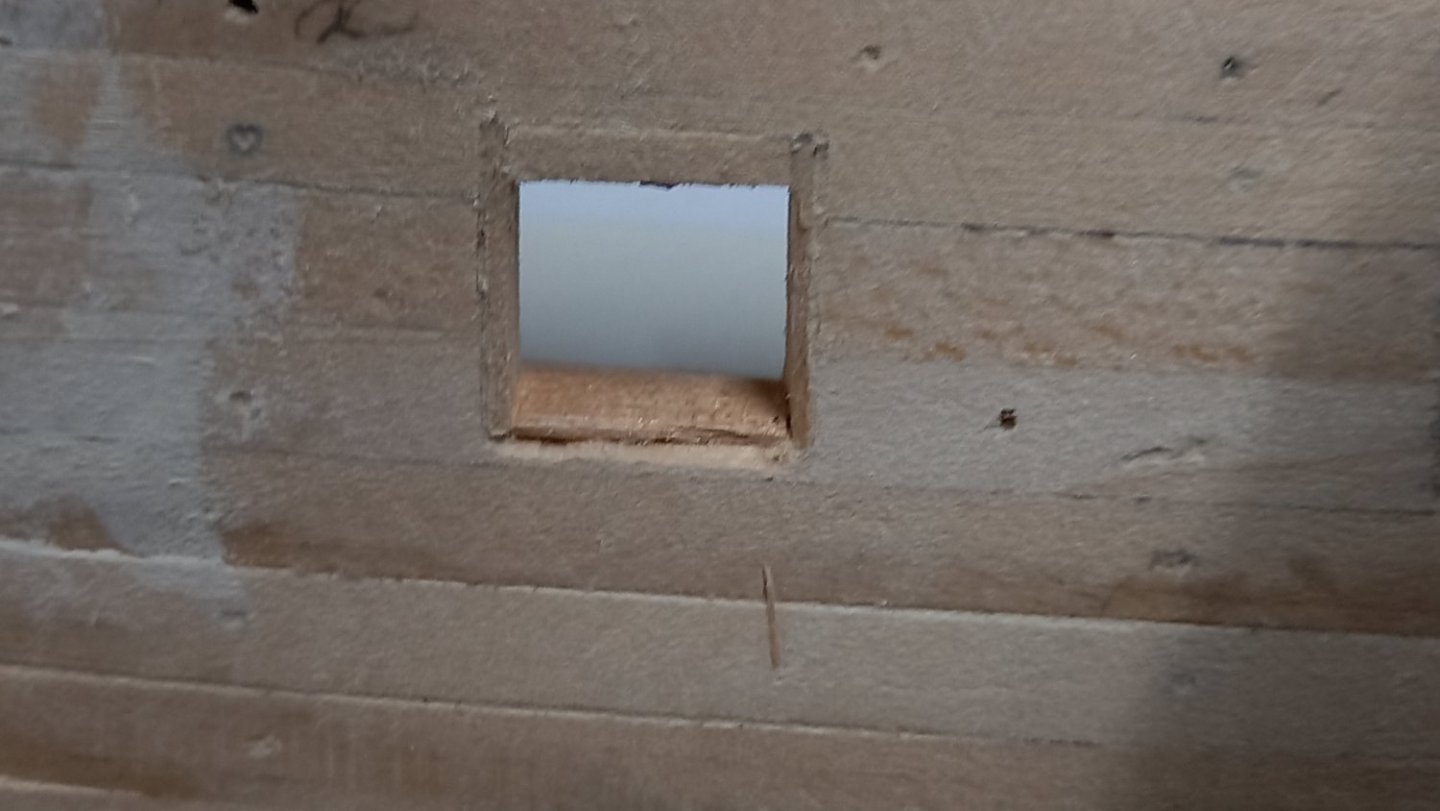
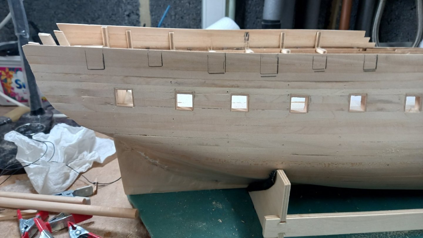
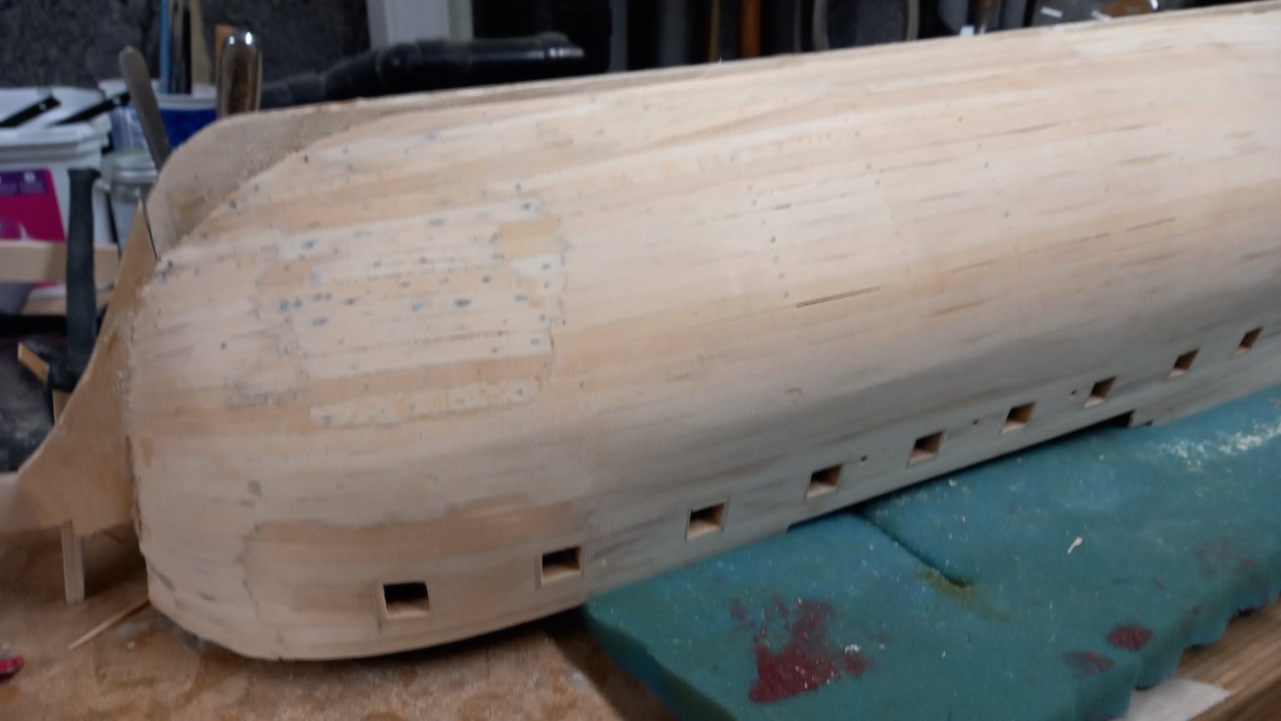
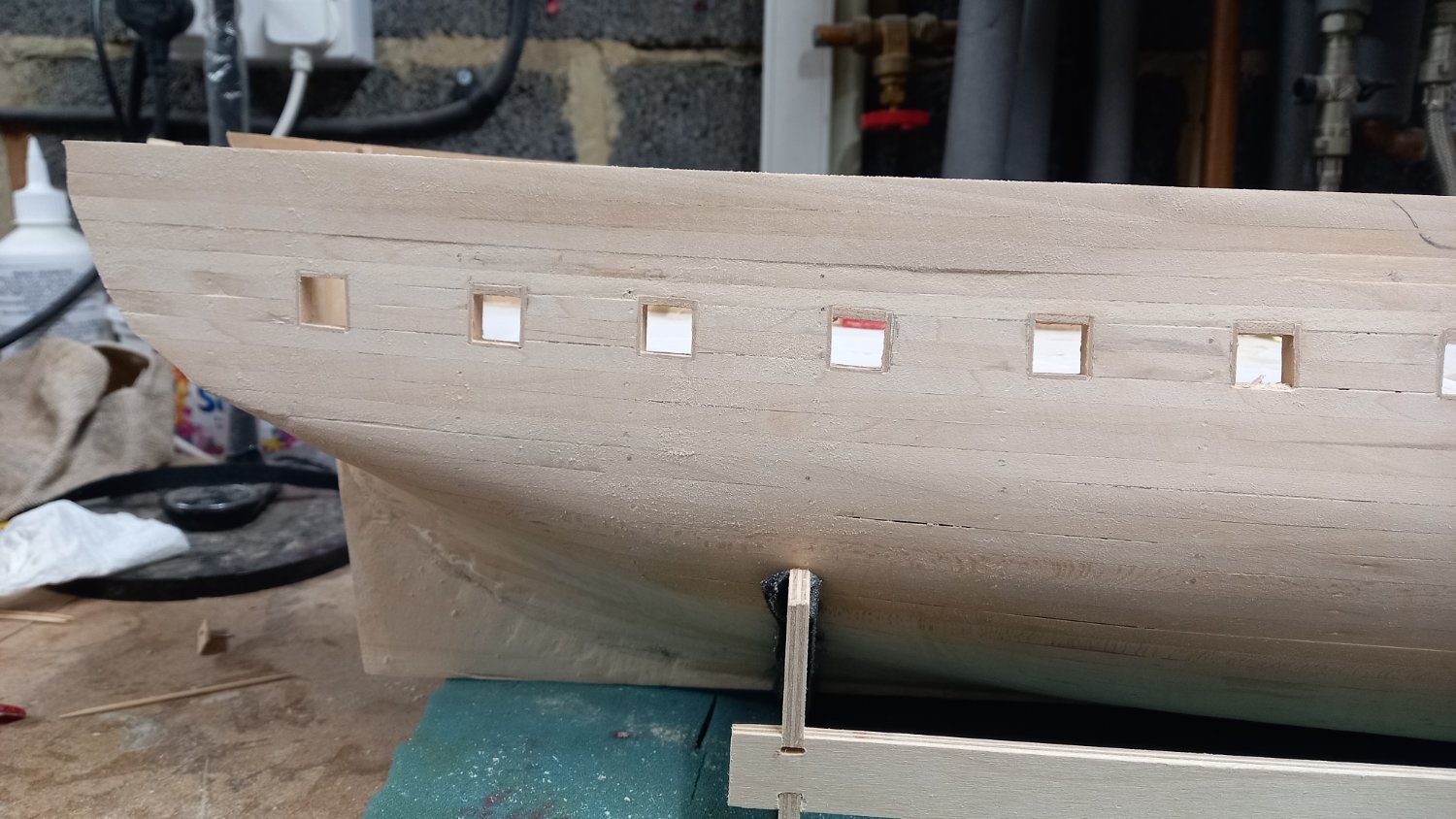
Extra lime strips 1.5mm x 6 mm were added to the hull in the area where the first two gunports are cut at the curve of the bow. After sadding down these planks , I then cut the remaining two forward gunports on both sides and added some 4 x4 mm walnut pieces to simulate the frames on the inside of the hull. Some reduction of the upper bulkhead frames was required so that the gunports were perpendicular to the hull. Further preperation to the gun ports to ensure that the correct sizes after the gun port liners are fitted .These sizes were taken from AOTS Diana and not the kit instructions.

Roughly sanded the hull ready for filling and final sanding to take place but first fitted the gun ports liners using various jigs to ensure the sides ( fitted first) are parrallel with the frames and the top and bottom are parrallel with each other and follow the line of the deck. When checking my stock I found I only had lime in 1.5mm thick lime and not 1 mm so rather than making the gun port holes bigger I decided to use some Tanganyka , perhaps I should have sanded it first before using it as I am reluctant to sand them inside once fitted as the corners are very neat.


There is still a fair bit of work going on before I can move onto the second planking such as gluing in place the 1x 3mm walnut planks in the area below the stern counter and cutting the gun ports for the upper quarter deck.I also need to remove the material from the deadwood area, remembering to taper this towards the bottom as with the stern post and rudder at a later date.
I now have a fair amount of boxwood for the second planking above the water line. ( very expensive and quite yellow, unlike my other boxwood stock for some reason) Also there is something I need to figure out is the difference in the thickness between the 0.7mm boxwood planking and the 1 mm thick walnut at the water line. I am sure the previous logs of the Diana will hopefully be of aid with this. Unfortunately I was unable to source 1 mm thick boxwood so I went with 0.7mm thick. I still think I will use the boxwood as if not that would mean I have spent a small fortune on both maple for the decks and now boxwood for the hull both of which would probably never be used.


HMS Diana 1794 by DaveBaxt - Caldercraft - 1:64
in - Kit build logs for subjects built from 1751 - 1800
Posted · Edited by DaveBaxt
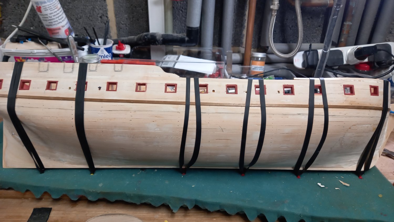
I have been making steady progress with the second layer of planking and completed the first 2 of the 4 zones below the main wale. This has been mainly 0.7mm thick boxwood above the water line and I am now into my 3rd zone and have started laying in some of the 1mm thick walnut strakes which needs a bit of soaking for 20 mins prior to bending around the bow. .My plan was to go from 2 x 4.5mm wide boxwood giving me a width of approximately 9mm, to 1x 5mm and 1 x 4mm walnut which also gives me 9mm, however the walnut strips are quite a bit oversize so needed a shaping to remove any gaps. when the different woods lie next to each other. I continued this method untill all the planks were below the water line and continued with walnut only.
I have also glued the boxwood stern post into position at this point
I have also given some thought to the copper plates and have decided to not use the ones supplied by Caldercraft and use them for experimenting with only. I have ordered some photo etched plates from Amati which seems to be the go to copper plates for a number of people other than those using copper tape. It was my original idea to just paint the bottom with copper and verdigis green to give the bottom a look of weathered copper but thanks to DavidEN I have now decided to emulate his HMS Diana and weather the copper plates using Red wine Vinegar and Miracle grow. I still need to do some experimenting using the CC supplied copper plates to find out if it is better to do these plates individually or after they have been glued to the hull. ( I think doing them individually might be a long process so might see if these can be done in groups of say 50 off the model)I also think I will use thick CA glue for securing the plates directly onto the un-treated walnut. I am not sure about sealing the wood first with Shellac as origonally thought.
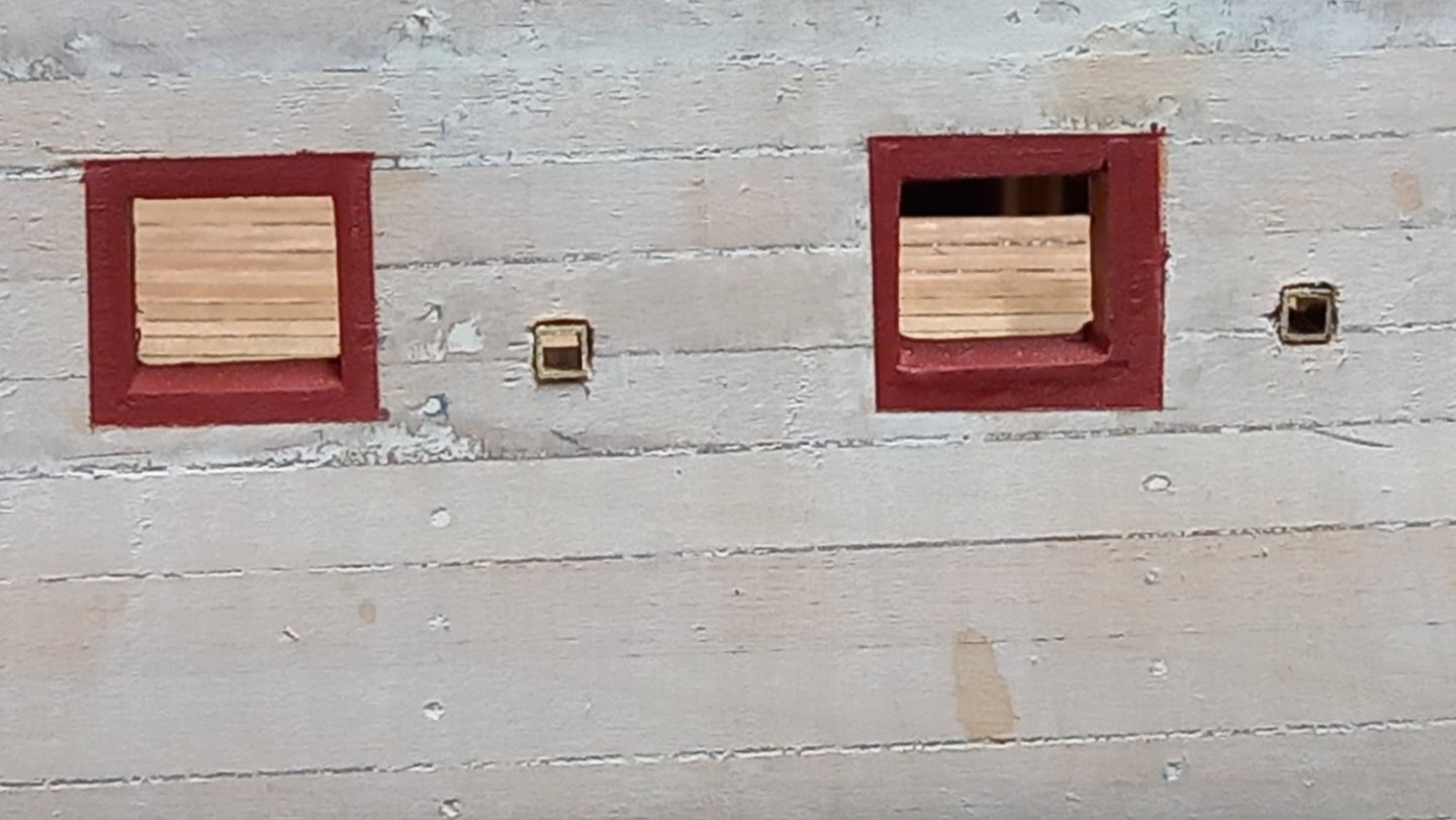
I have now received the replacement copper plates from Amati and you can see from the photo that there is a big difference in the size of the nails. The Amati ones being much smaller . Infact the CC ones look more like rivets. So at the moment I am very happy with them . So far so good.