


DaveBaxt
-
Posts
1,297 -
Joined
-
Last visited
Content Type
Profiles
Forums
Gallery
Events
Posts posted by DaveBaxt
-
-
-
I had assumed these were made from iron and hence the brass etched pintle straps are blacked using various blacking solution (Brass black being my preference) I then started wondering as to the effect of electroloisis between copper plates and iron pintlle staps, especially in salt water.perhaps there is something placed between the straps and the copper plates to reduceelectrolisis, or perhaps the pintle straps are made of copper too. I am asking this question due to finding a model wiith the brass etched pintle straps being painted with copper paint or perhaps the straps could be made from copper imstead of brass and allowed to weather naturally. Personally I rather prefer to have the pintle starps to be Iron as I like the contrast between the copper and iron but wonder what others think of copper pintle starps, when copper plates are fitted to the hull and how accurate this is in reality ?Thank you.
-
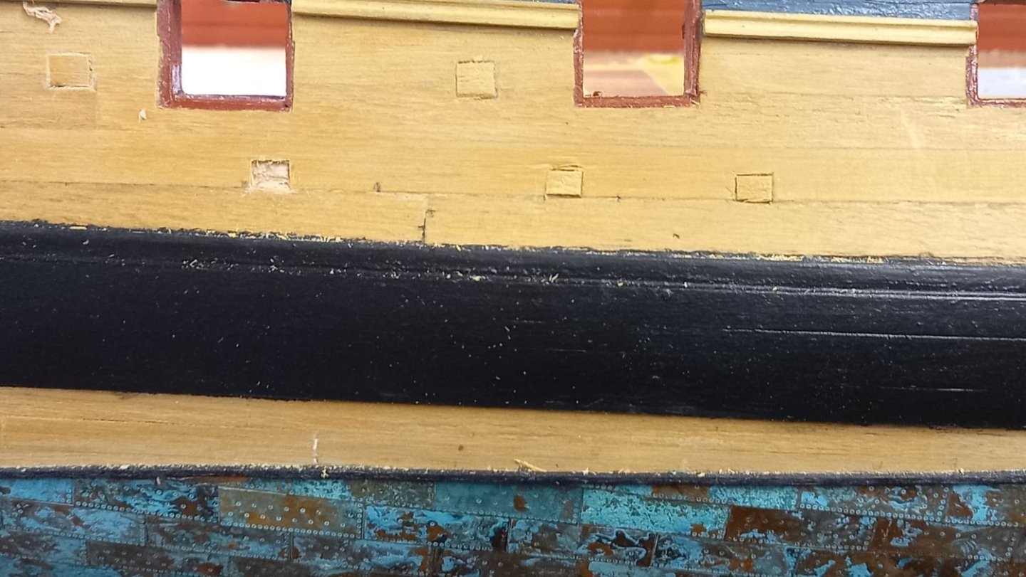
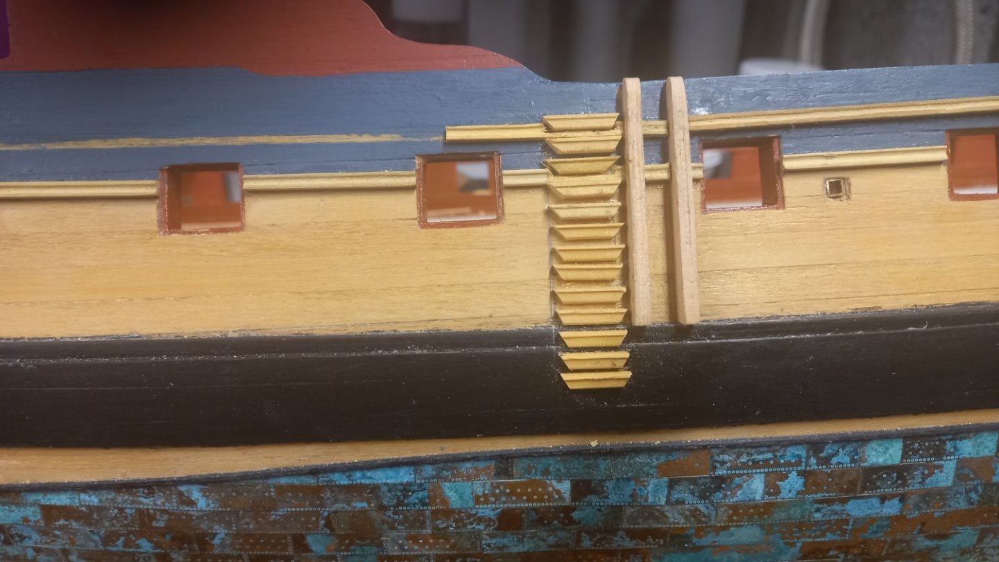
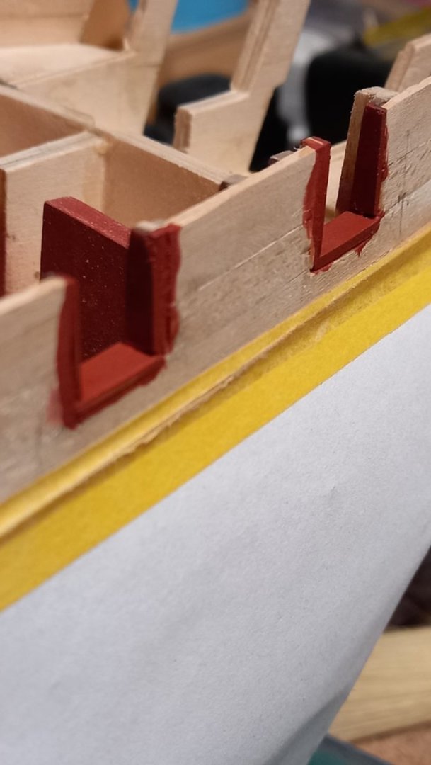
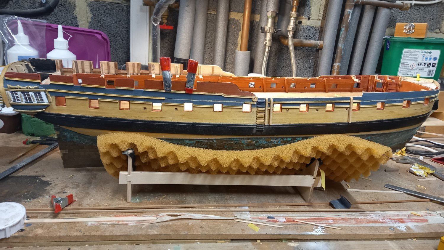
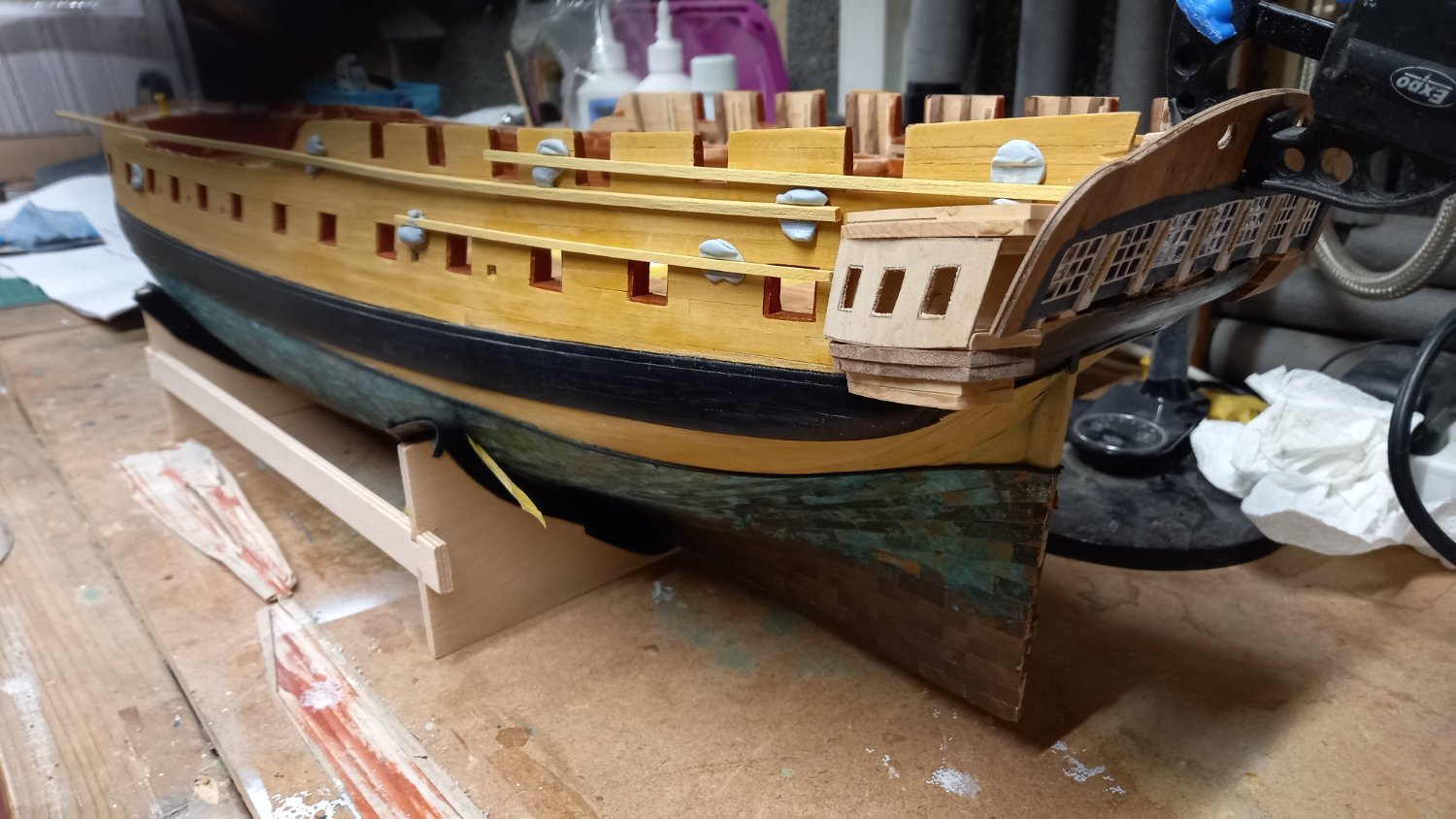
Small progress due to another leave of absence ( holliday). Cut out the sections for the scuttles and oars so that the doors would lie flush with the hull and also the 4" scuppers . I only fitted the 3 forward ones as I thought I would ensure the main mast chainplates were fitted to try and miss these if possible. Regards the hinges for the doors, the ones supplied are far to flimsy but managed to find some extra ones left over from my Endeavour kit which is the same 1:64 scale so a bit of improvement I think. I am also in the process of gluing the upper focastle drift rail but still need to make the decorative scroll out of boxwood as per the quarter deck drift rail. Some cleaning and touching up of paintwork is required.
-
-
1 hour ago, dunnock said:
Thanks to Dave and Andrew for your kind compliments. Yes it's beginning to take shape and I'm quite pleased with how it is turning out. Apart from planking a portion of the lower deck, so far I'm just following Chris's instructions which are comprehensive and easy to follow. I will be using Steel and Lees as further references for the masting and rigging as I have with previous builds.
David
Great books an resource for masts and rigging.
-
It's starting to take shape now and after a couple of early minor hiccups you must now be pleased with your progress so far. Are you just following the instructions or are you using any other resources? Looking forward to seeing your progress as I think your workmanship is on a very high level.
-
10 hours ago, RolBerg said:
Thanks. Looked at the drawings and building instructions to the Black Prince and they are pretty vague so i will be asking a lot i guess.
I found the drawing of my first build very frustrating but still do to some extent however there are some better ones out there. There is a poll on here which gives you an idea of which kits have the better instructions. I have found Caldercraft very good, especially for rigging. I also understand that Vanguard are up there with the best and have become very popular. Something I am definately consodering for my next build. Anyway for now I agree starting of with a build log is definately the way to go .
- Keith Black and mtaylor
-
 2
2
-
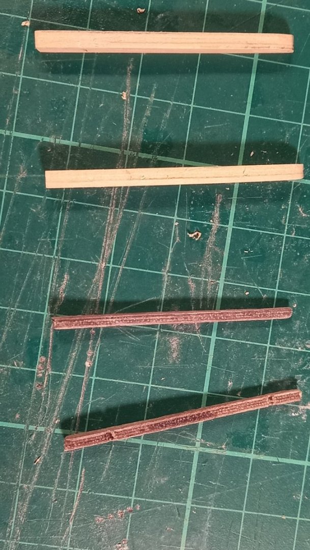
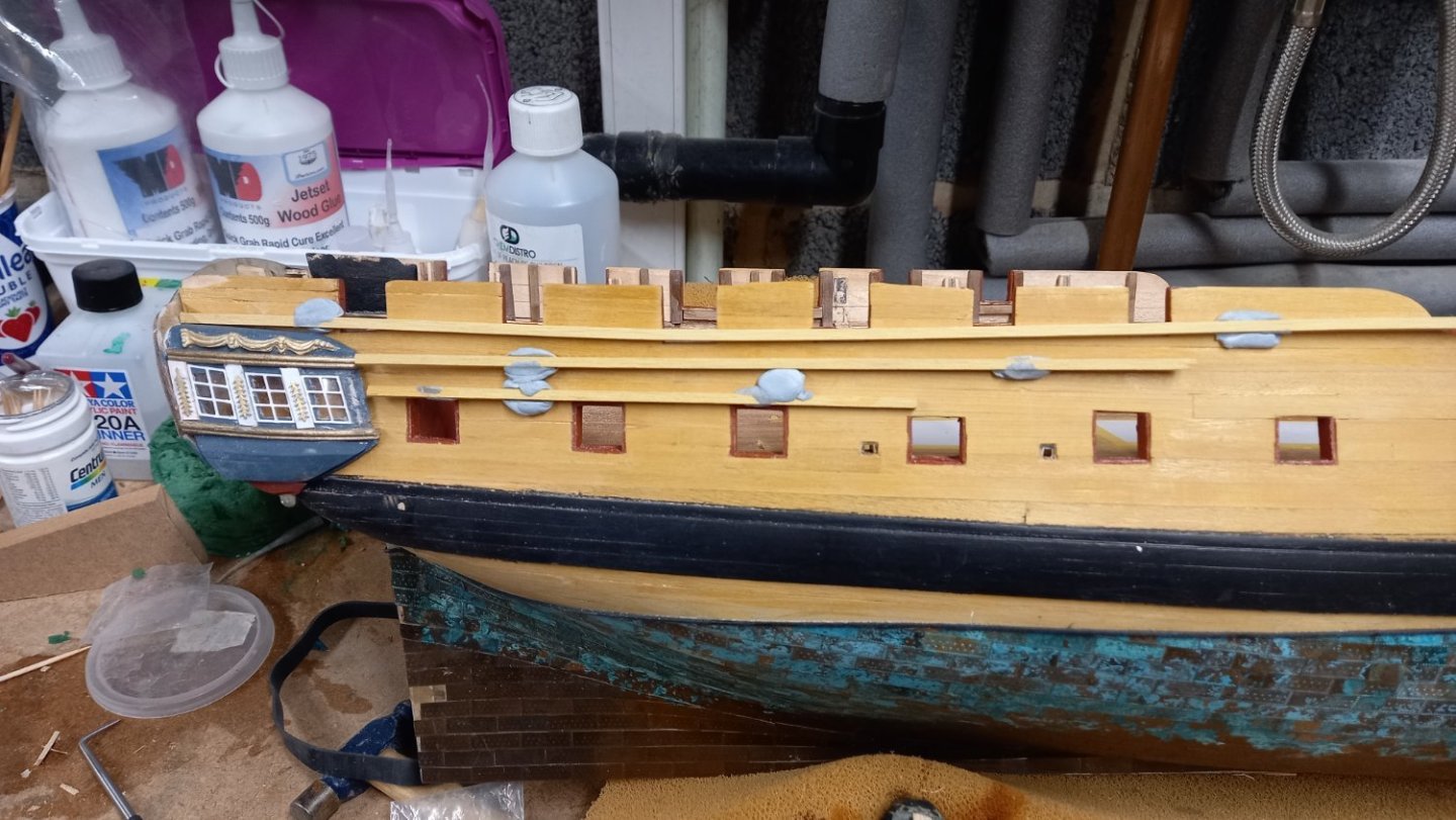
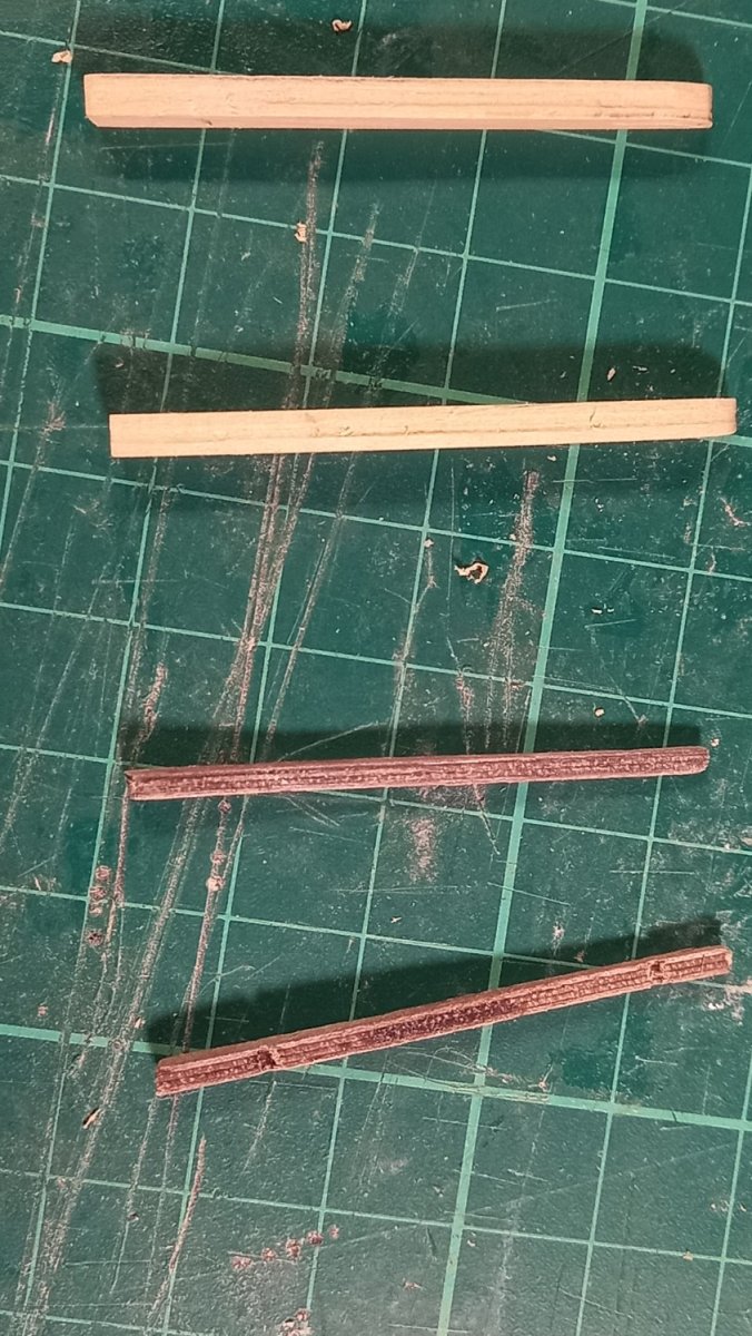
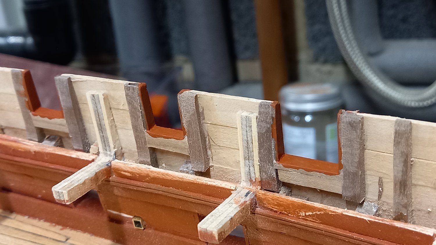
I have sepent the last couple of weeks replacing the different walnut rails supplied by Caldercaft with 2.7mm square boxwwod and made the the scrolls out of 1.5mm thick boxwood veneer. This has been my first attempt at carving using both 1.5mm Vee chisel and a 1.5 mm gouge. Not too bad but I still could do with a bit more practice. I also used Amatis shapers to get what I thought looked a pretty good profile of the rails but not as accurate as depicked in the AOTS book. I did try and make my own shapers out of safety razors but they did not turn out as good as the Amati shapers or by some fellow modellers on MSW.I also made up the fenders from 2mm boxwood sheet, which I already had in stock.


.thumb.jpg.d909acfd16daa0bdfbc3067b490bbbfd.jpg)
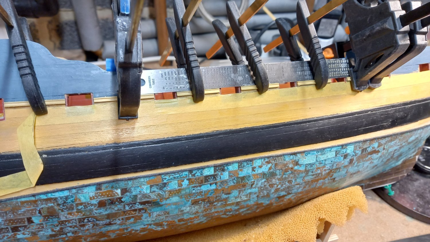
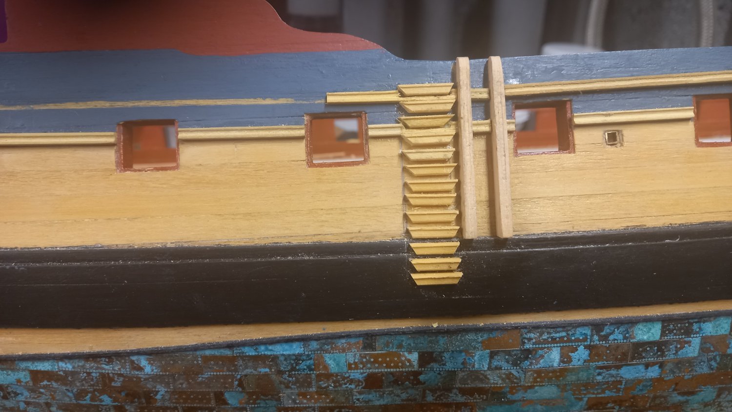
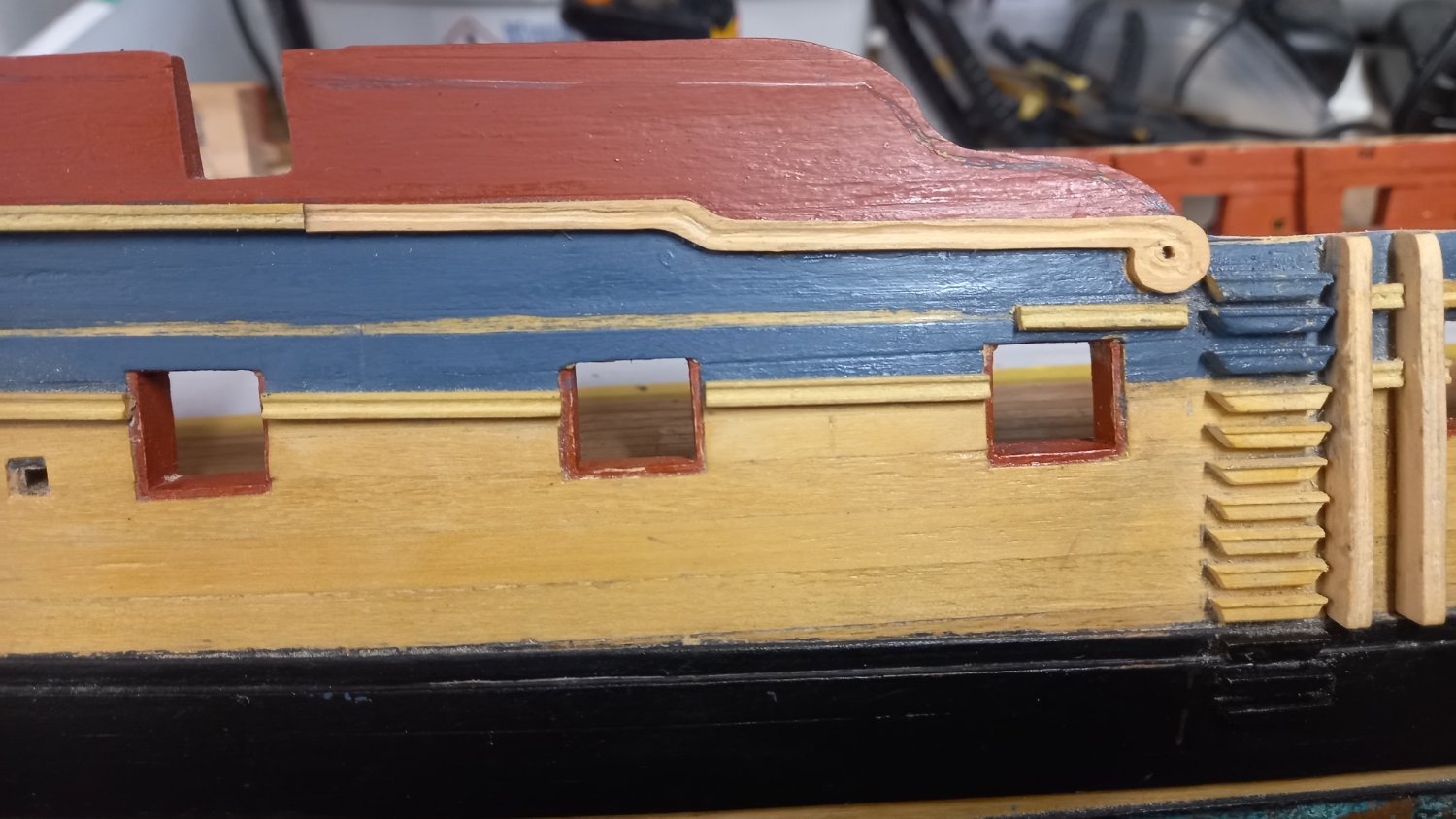
I have followed the Caldercraft instructions as per fitting of the upper sheer rails but have fiited the rails at the channels and left out sections of this rails to allow for the positions of the fore and main channels. I have two more rails to do to fit on to the hull which is the smallest of the rails which are the quarter deck and focastle drift rails. I have tried using 1mm square boxwood for these but think this is too small. So I have ordered some 1.5mm and 1.8mm square boxwood to see which looks the better and whilst I wait for this to arrive, I can move onto a number of jobs which I have put on the back burner for one reason or another and I need to return to these to finish off the work on the hull. This work is mainly the sweep ports, ventilation holes and scuppers.
Once again I will be following with the Caldercraft instructions and moving onto the head rails and what I also think will be another daunting task.


-
Welcome and good luck with your first model ships. Don,t forget to ask any questions as there is a wealth of knowledge on MSW.
- mtaylor, Keith Black and RolBerg
-
3
-
-
2 hours ago, allanyed said:
NB
Using filler blocks is a wise move. If you have not already studied it, the contemporary model at RMG may be of some help not to mention the plans they have of Diana 1794. Note that as she is post 1790, she does not carry her name on the stern which was by Admiralty orders (maybe not universally adhered to😀)
https://www.rmg.co.uk/collections/objects/rmgc-object-66303
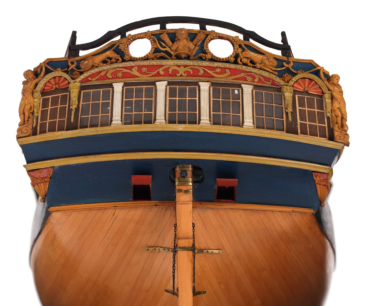
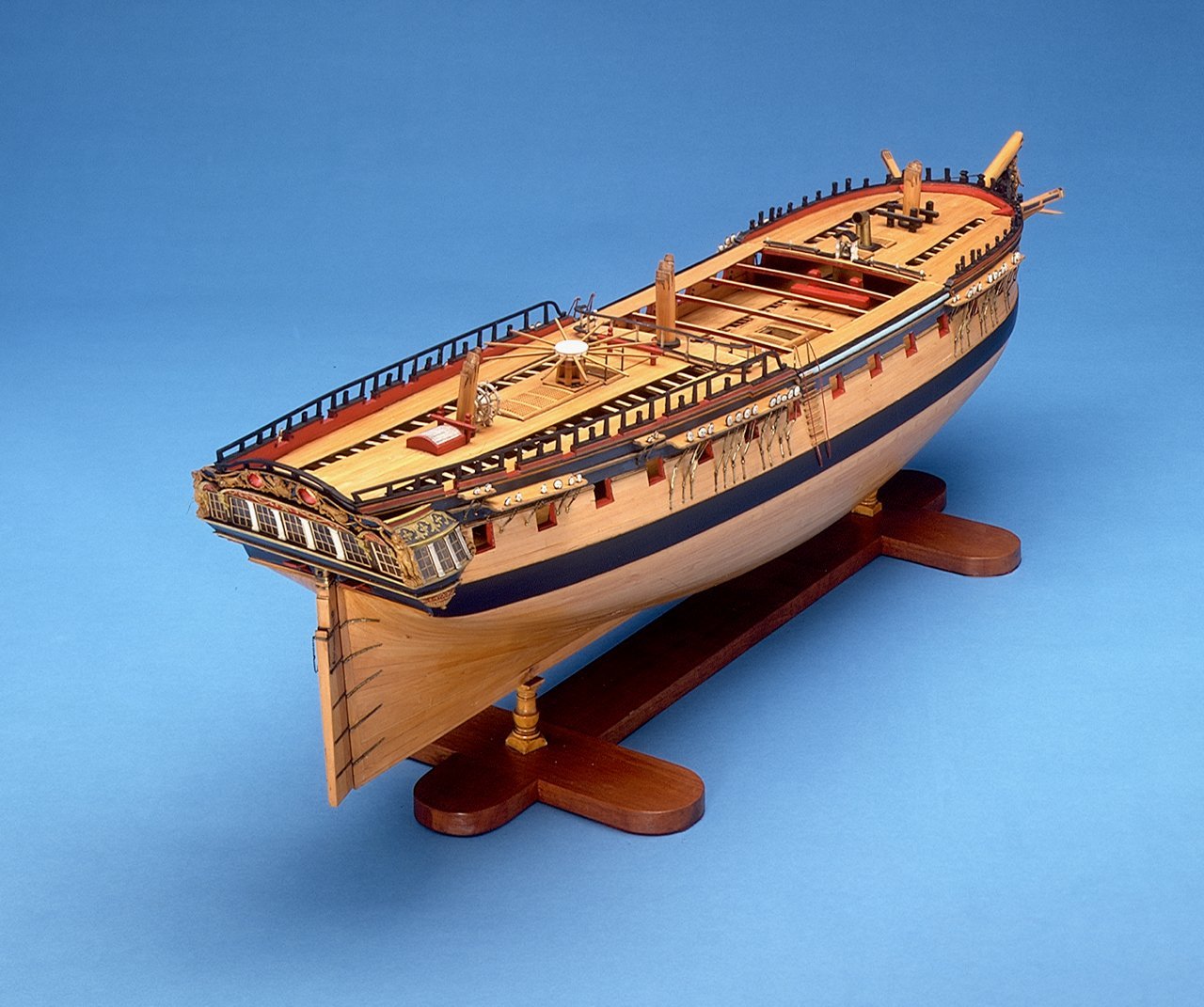
Some good photos there Alan which clearly shows a very high standard of workmanship, something we can hope to achieve.
-
34 minutes ago, Theodosius said:
I'm not sure jet, if I became a fan of your heavy copper-wethering, but I do like all the reast of your beautiful build model!
Thank you Theodosius for your coment .Yes I think I went a bit overboard with the weathering and tried to be a bit too reralistic. If I am honest I am not sure if I would use copper plates again as I still believe the nails on the Amati plates are still too big for the scale. I have heard a number of modellers using paper plates dipped in shellac. I have also been doing some experimenting airbrushing acrylic ( aged copper and verdigris) and thought I might try this instead. I think the verdigris look is a bit like marmite tou either love or hate it.
-
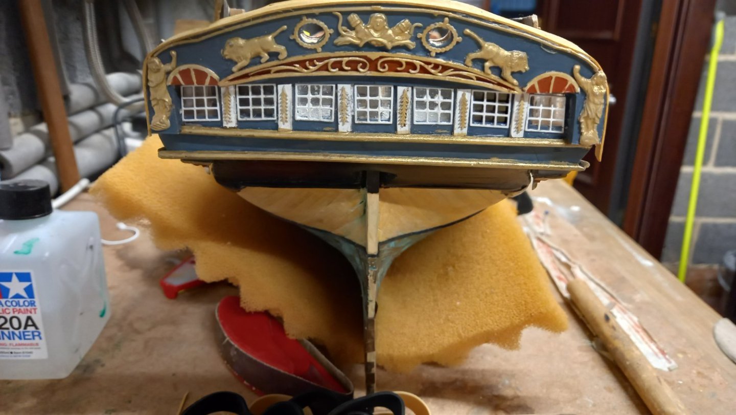
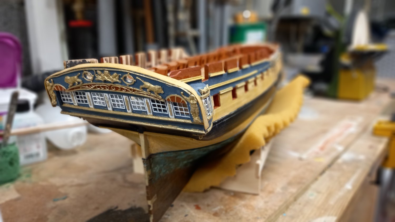
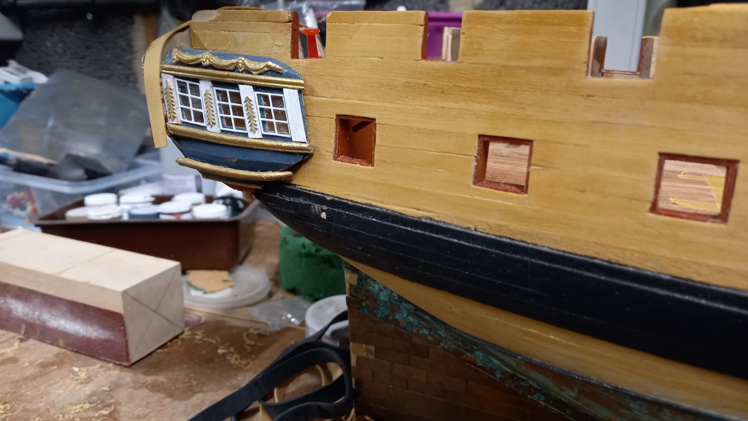
A big thanks to DavidEn, Dunnock , Beef Wellington and Ray for all the help with their fantastic Diana Build logs and their approach to the stern and quarter galleries. I have still not managed to get it exactly right and ended up with every thing being a little too high I think .After several attempts using the parts supplied I ended up making a lot of the parts myself but thinking back I probably could have used the parts supplied but think the cast rails and some of the brass parts could have been better defined. I also used the blue paint recommended by Dunnock rather than the dark blue supplied by caldercraft. I also added an extra layer of 1mm wood to the transom and I made the tefferail using 3 mm boxwood to get the concave effect on the lower curve. I also used the brass windows and painted them white after pickling and priming all the brass parts..
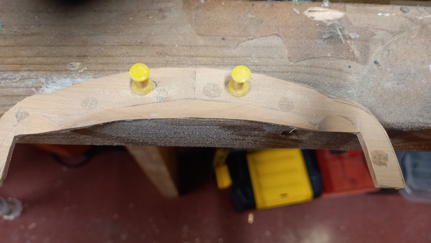
Making tafferail out of 3 mm boxwood and shaping to take brass parts and to give a concave effect
Gluing tafferail into position
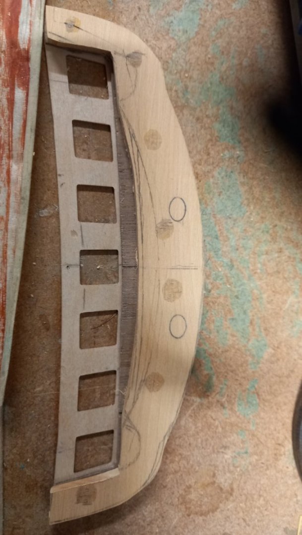
Placing decorative rails in position to line up with the position of window quarter galleries . This was rather difficult so ended up making new window frames to hopefully look right . Below Temporary lining up of quarter galleries with stern fascia.
 In
In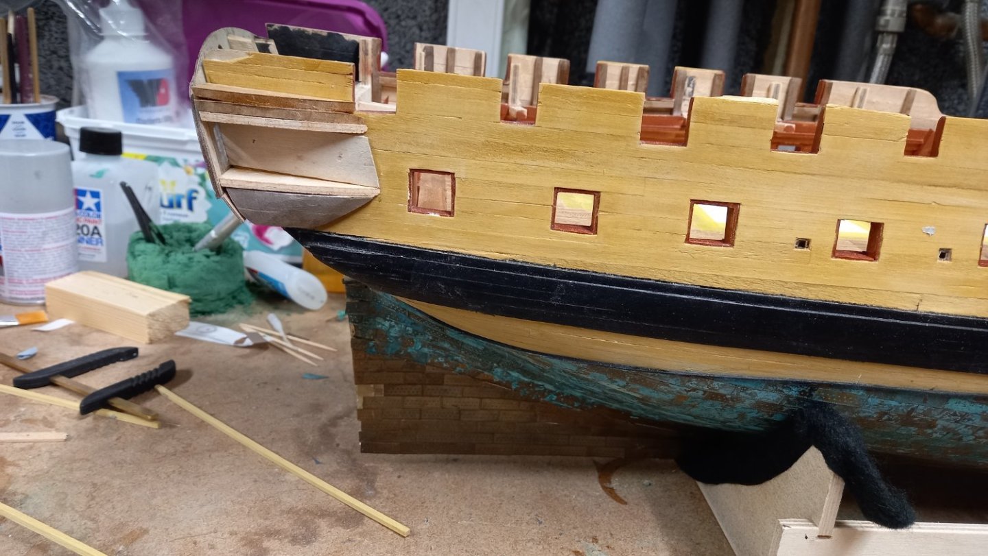
After several different checks and double checking that everything was lining up correctly .In the above photo you can see that the frame for the quarter galleries is sitting too high, so removed and replaced so that the lower edge of the quarter gallery frame lined up with the upper edge of the counter. This ensured that the windows of the stern gallery lined up with quarter gallery windows. There is however some compromise with the lining up of the bottom of the lower gun ports with the bottom of the quarter gallery windows and think this maybe due to positioning of the gun ports to fit the bloomfield cannon so that the gun barrels would lie central in within the gun ports.
First I glued the 0.8mm plywood back plate into position followed by the 3mm plywood top and bottom and finally the 0.8mm window fascia, also made from plywood. All these parts were eventually made rather than the supplied parts to get what I felt was a better shape.and position.
Starting to take shape. There is some more decorative rail to fit to the underneath of the quarter galleries and the upper and lower stern counter but hoping it will look presentable. Also one or two decoratie parts to fit and some touching up of paintwork, then fitting of the Tafferail to the stern.
Gluing the stern fascia onto the the transom has been solved by a number of ingenious ideas from previous Diana builders and due to the inceased thickness of the tafferrail (3mm) I was expecting some difficulty with bending the stern facia into position and I thought the use of heavy gauge rubber bands would be sufficient to bend the stern fascia into position. I ended up with a bit of overkill using a combination of clamps and rubber bands. I also thought of using appoxy resin but only had 5 minute
setting time at hand so ended up using ordinary PVA glue so hopefully this will be strong enough.The upper deck supports definately came in hand as did the very large rubber bands.

Unfortunately I have made several mistakes and have become quite frustated with this section of the build, fortunately I think the mistakes are hopefully cosmetic and nothing too major. Although my Diana is nowhere near the standard of the previous Diana builds as my skill levels are somwhat under the very high standards of the many experts on this forums. Hopefully the result is still quite presentable because, as of this moment ,after what I feel has been a long time.I do not feel inclined to change anything on this section of the build for the time being. Perhaps I could return to this at a later date and replace the decorative strips using something more appropriate than the ready made walnut strip I had in stock. I do have some boxwood which would be better suited and using shapers for the required profiles. This is what I intend to do with the rails running along the hull . I have decided against adding the ships name to the upper stern counter as I understand this was not the pracice for this period but could be wrong.

- DavidEN, Theodosius, dunnock and 8 others
-
11
-
-
Sorry to hear you are having issues with the first planking. That edge bending looks tha same as mine so not sure if I am doing the same as you. Perhaps filler blocks would have helped but perhaps not needed with the number of bulkheads on smaller model. It will be interesting to see what Chris thinks. Good luck and hope you get sorted. Dave.
- dunnock, Dave_E and Ryland Craze
-
3
-
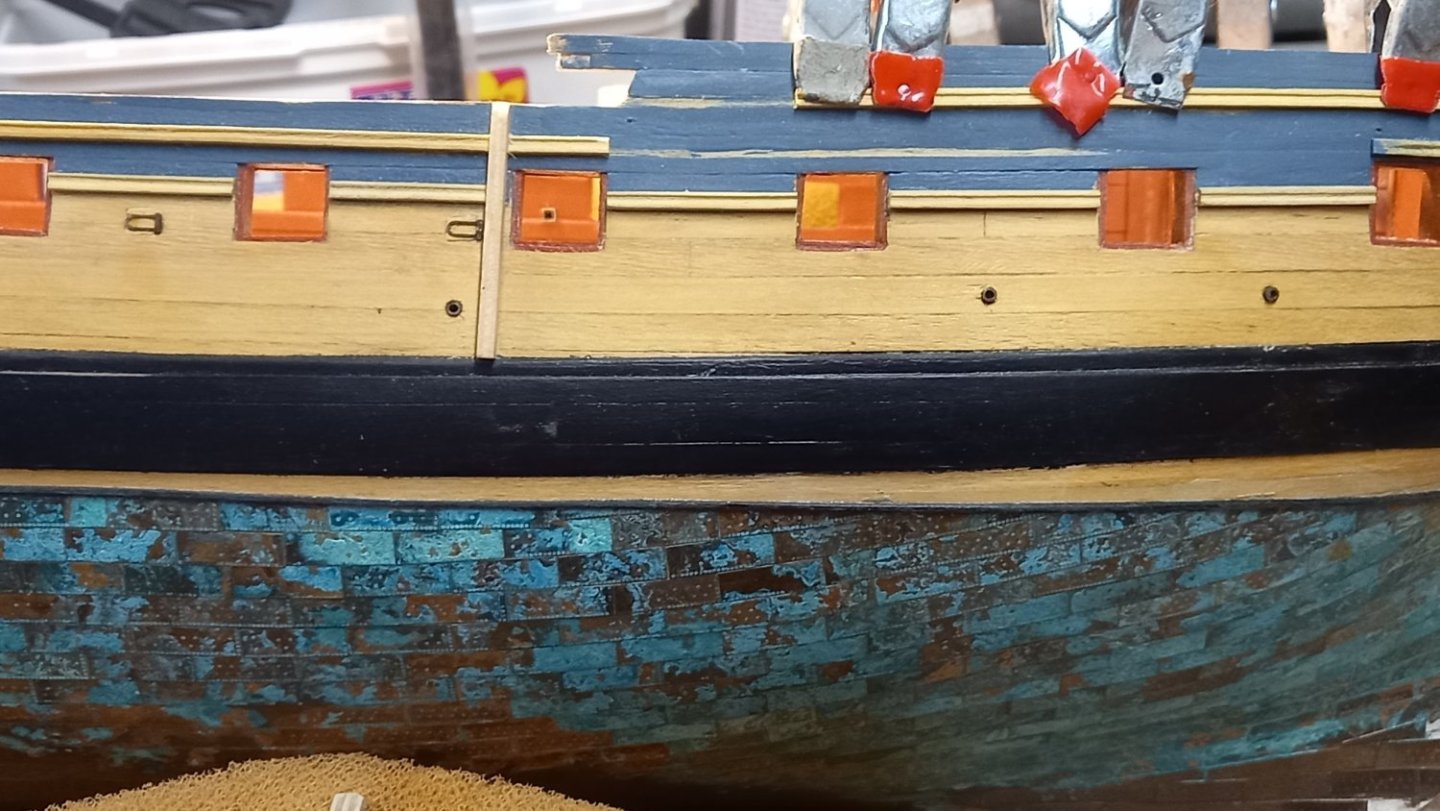
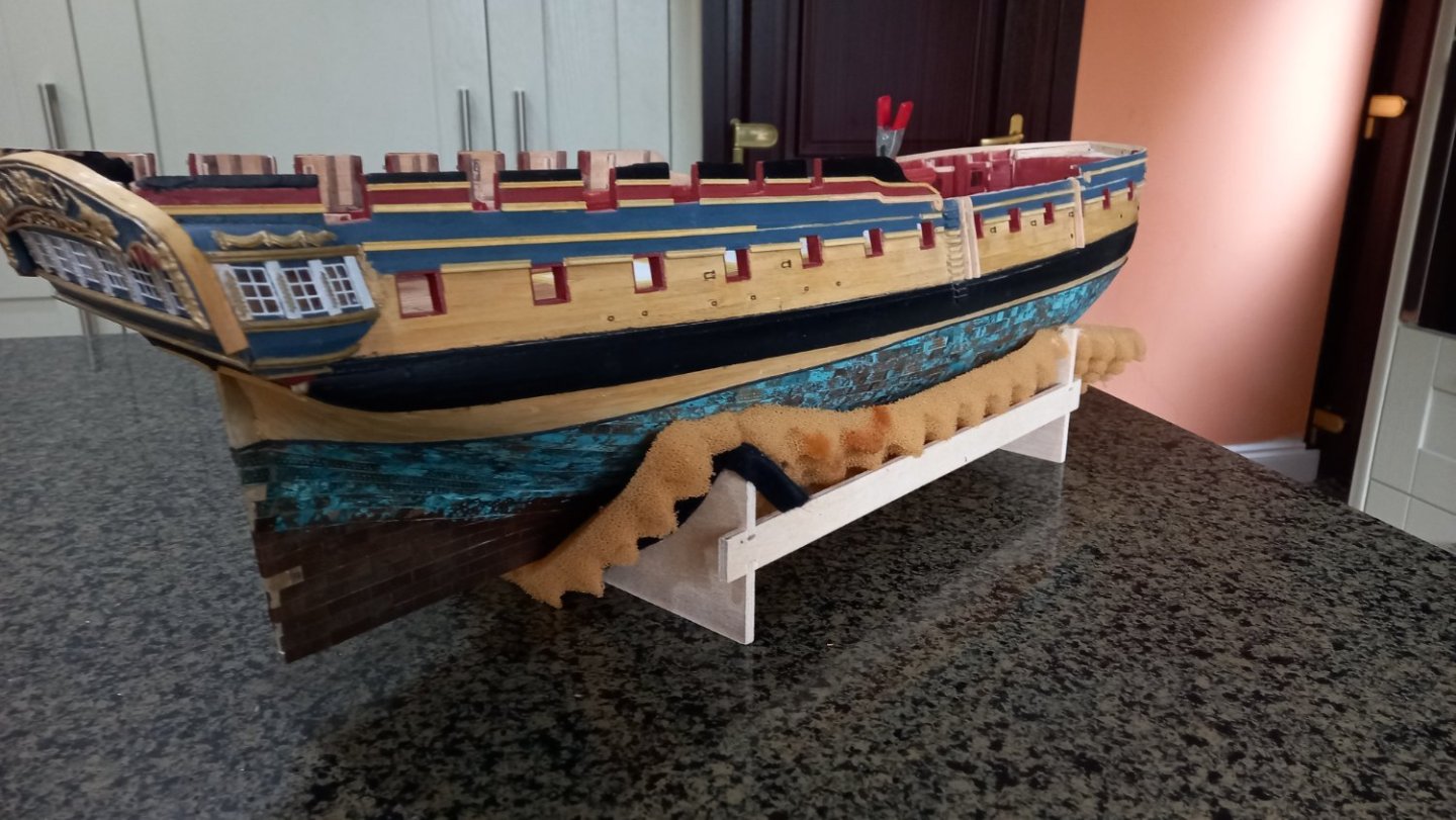
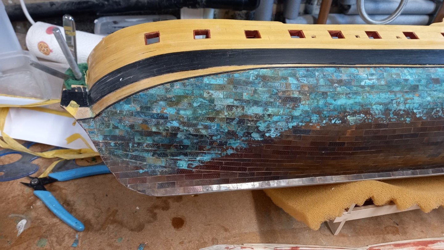
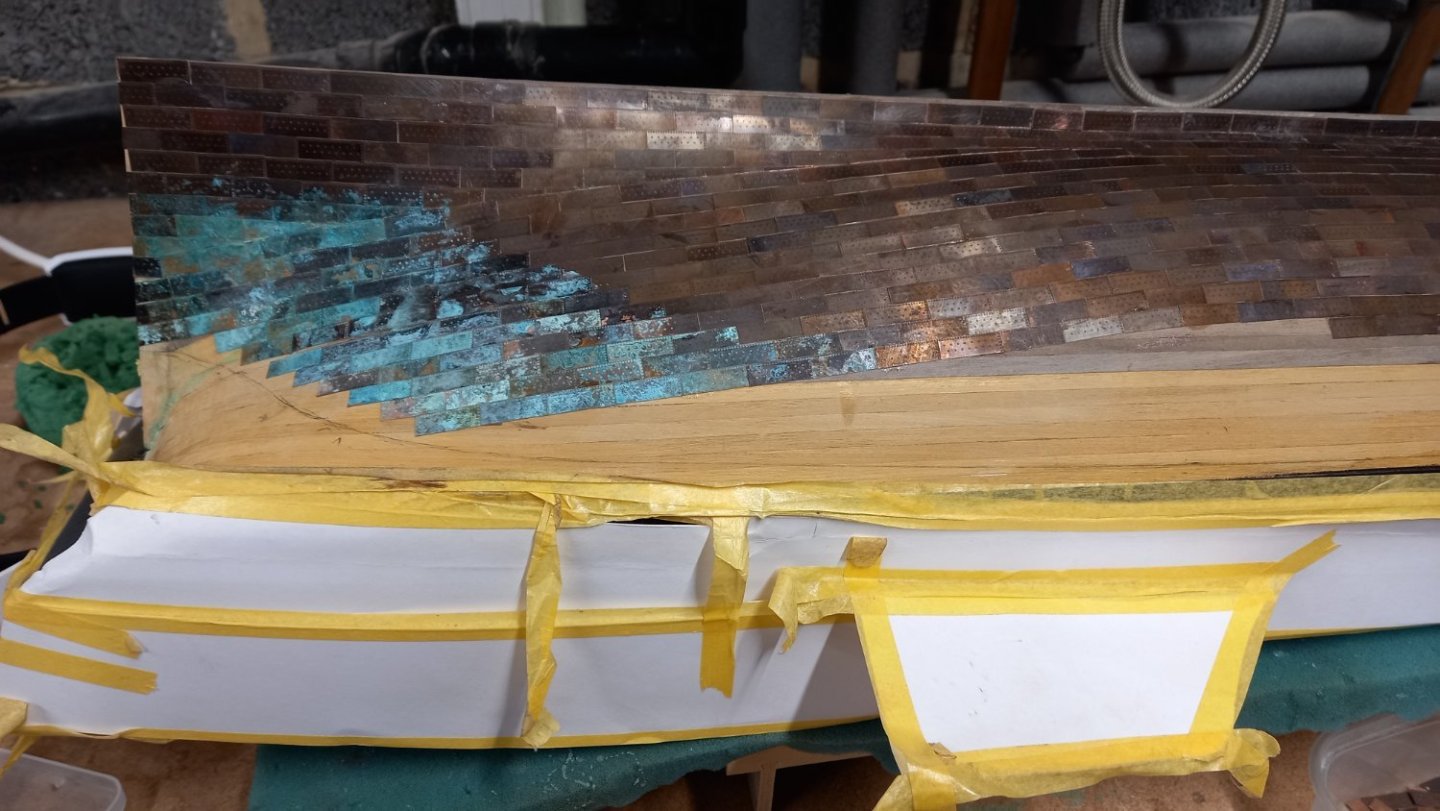
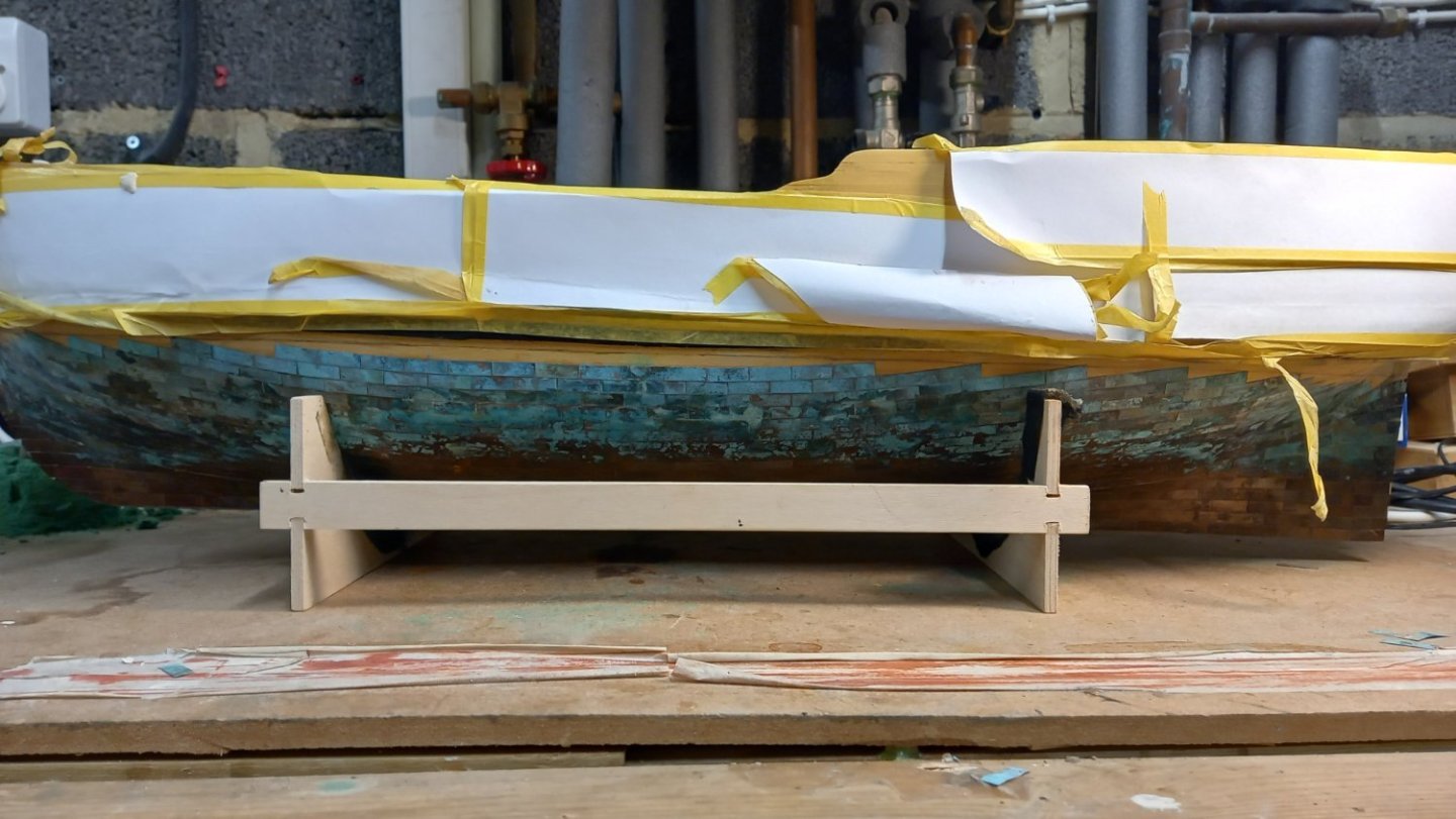
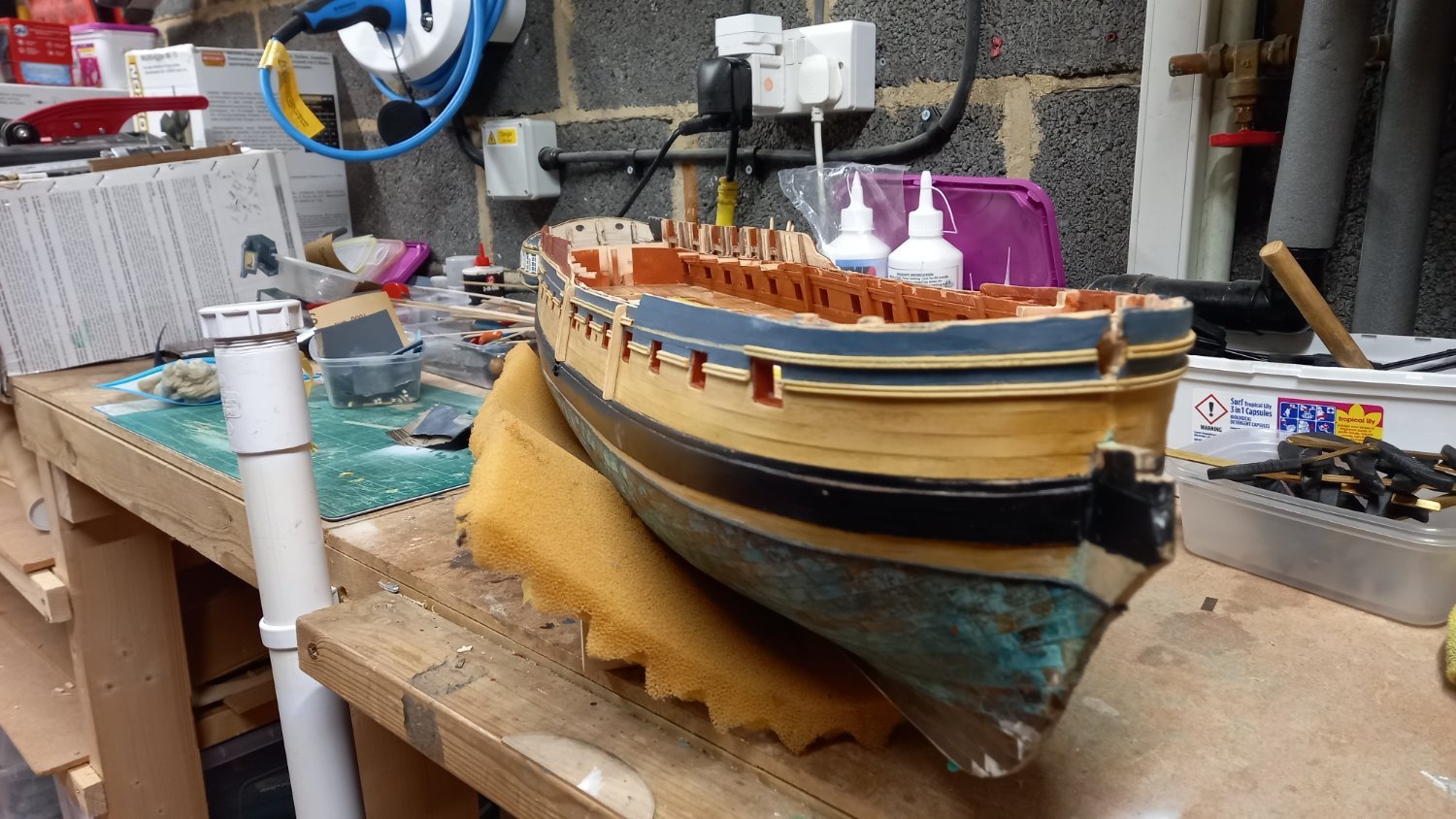
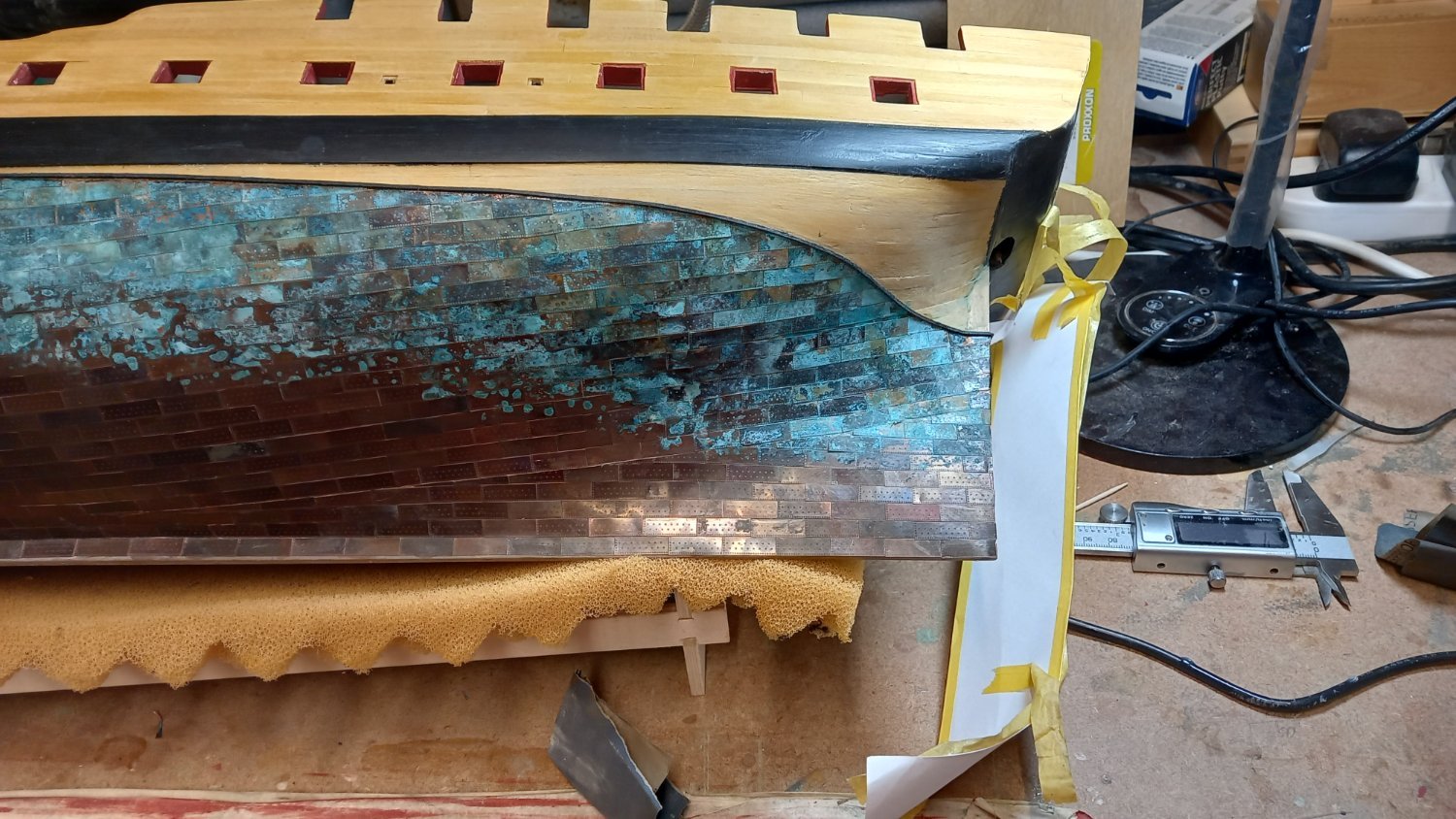
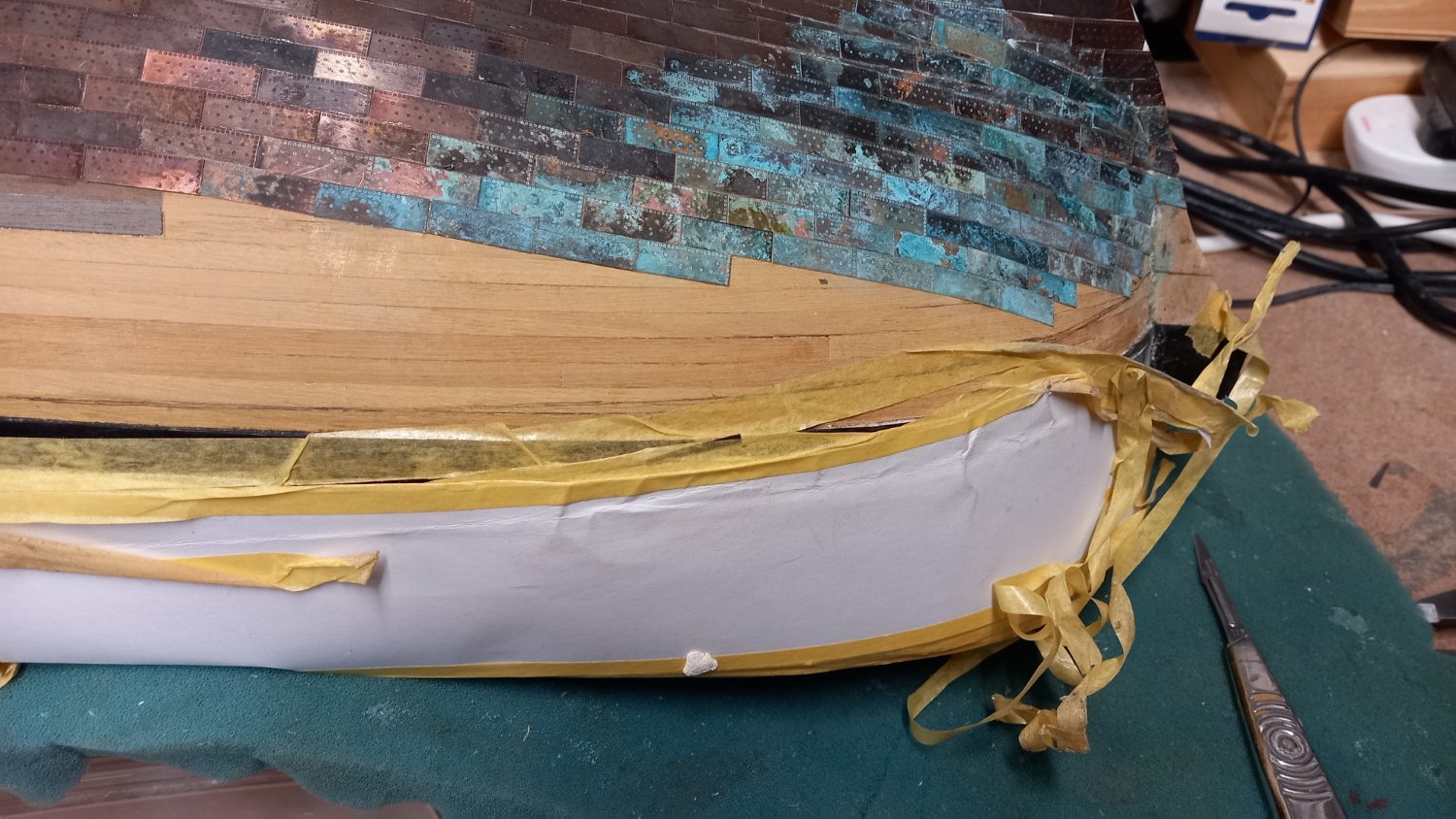
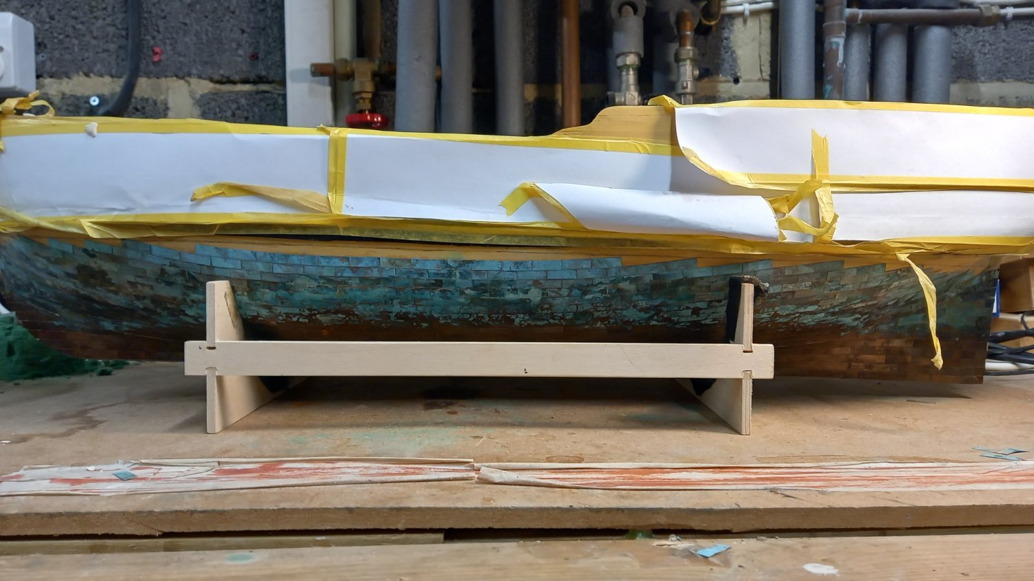
Slow progress with fitting copper tiles due to holiday in Switzerland and returning with Covid so have not felt like doing much other than completing the coppering of the hull and then attaching a 1mm x 1 mm black strip for the water line then making a start on the other side. I wasn,t entirely happy with the port side gore line as such , so using a different approach I used a 6mm wide walnut strip rather than tape to ensure the correct way the tiles would lie and butted the plates up to this strip. This appeared to work best for me but understand there are much better coppering jobs than mine out there but apart from working with hazardous chemicals and smelling super glue I am unsure of aging the plates to this extent is something I would consider doing again.There are still a few areas such as along the stem and stern posts that require attention and still the rudder post to do but in the main that is the copper plates complete. Few!

 O
O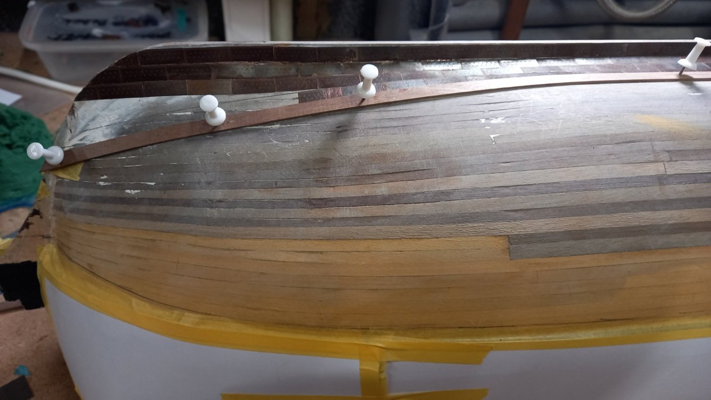
Once again I now draw my attention to the Stern and Quarter galleries and still wondering to how far I need to go with replacing the parts supplied with kit. I have notices a few modellers replacing several parts including the supplied brass etched windows together with some of the walnut parts with boxwood. I do have some boxwood in stock spo perhaps I will change to this but as far as the brass etched windows , as yet I have not decided which way to go. I used the ones supplied with the kit for my Endeavour and these looked fairly presentable.
-
You definately have your work cut out there.Being a newby myself and currently building the Diana but not as far on as yourself I have found the model dificult enough without correcting someone elses mistakes but can understand the attraction.However it would definately be of interest how you approach this and to see how much is actually repairable but I wish you luck. Dave.
-
-
3 minutes ago, dunnock said:
Dave,
My understanding is that glass would be heavier even if I might be able to use thinner sheets. The density of glass is about twice that of acrylic sheet. Also I would be quite nervous of handling the size of glass sheet I need.
David
Very good points David
-
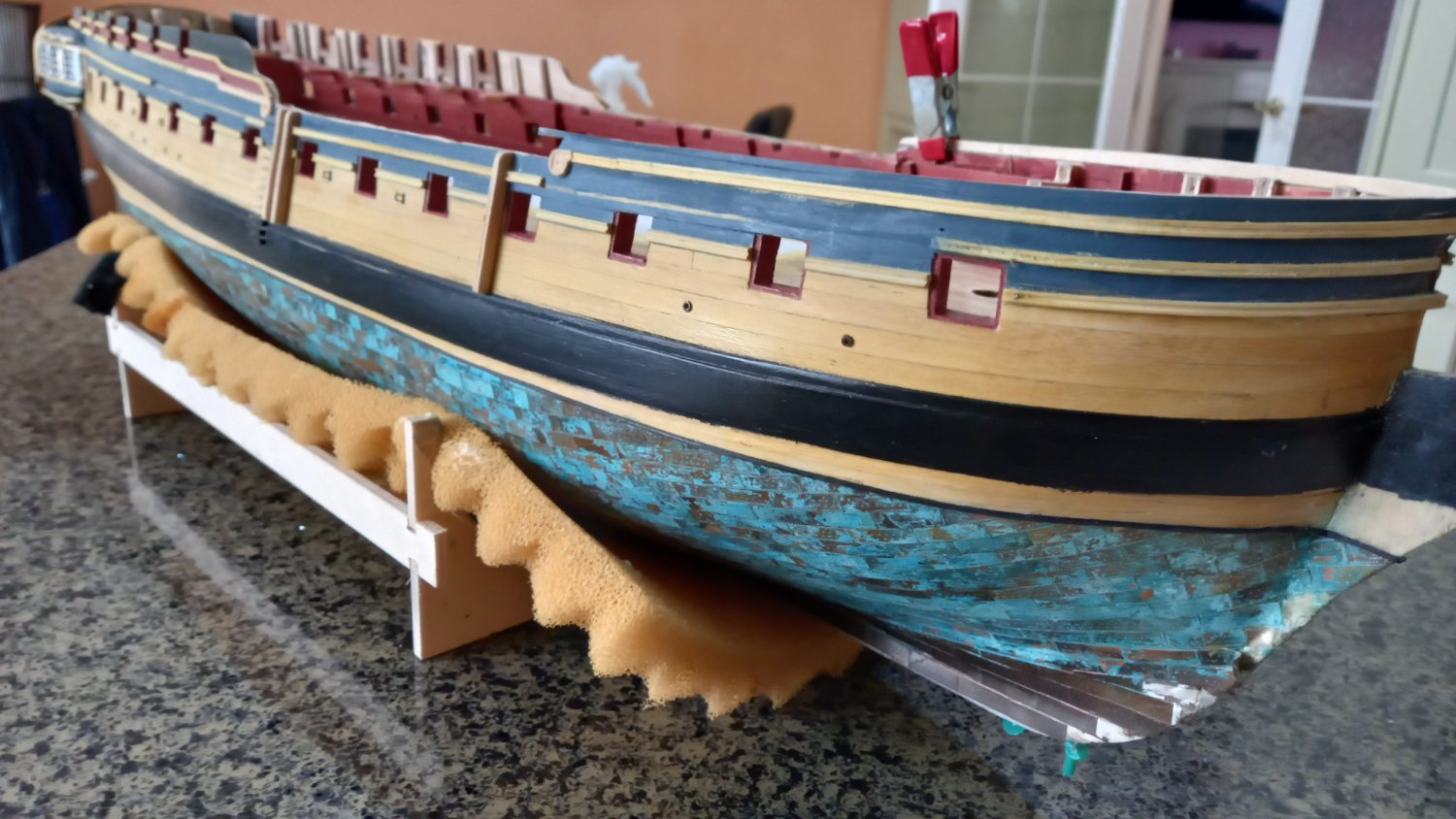
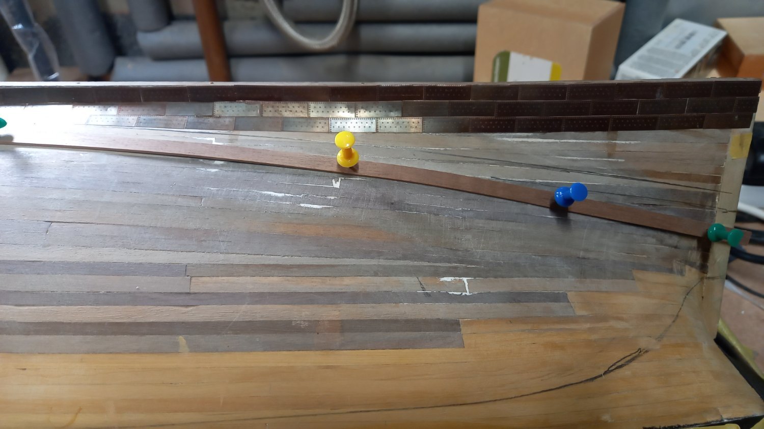
I have decided to change tack slightly as I have decided now after looking at the more recent builds of Diana I thought now would be a good time to start coppering the bottom. As previously stated I will be using Amati plates rather than CC plates as these are thinner and more refined. So that the marked indents look like nails rather than rivets. I would like to make special thanks to DavidEN, dunnock and Ray for helping me with the following process as it was due to their help with regards Weathering , jigs and placing of gore lines etc, all of which have been of great help.
After changing my mind several times I have decided to weather the plates first and using the same method as DavidEn using 1 part Miracle grow and 3 parts red wine vinegar. However before this process I pickled the plates and aged them using brass black which darkened them to a similar colour to aged copper. Here using the Amati etched plates was much easier as they could be treated with large numbers and then the backs cleaned off using fine sanding paper. It is my intention to only lightly patina the plates but gradually increase the patina towards the surface to simulate what might be the case in reality but not sure if this is correct. I found after rubbing the surface of the etched plates plates with 000 wire wool and soaking in acetone for a few miniutes then both the aging and patina would work so much quicker to get the desired effect.
Below Plates weathered using Brass black for a few miniutes then rinsed in distilled water.
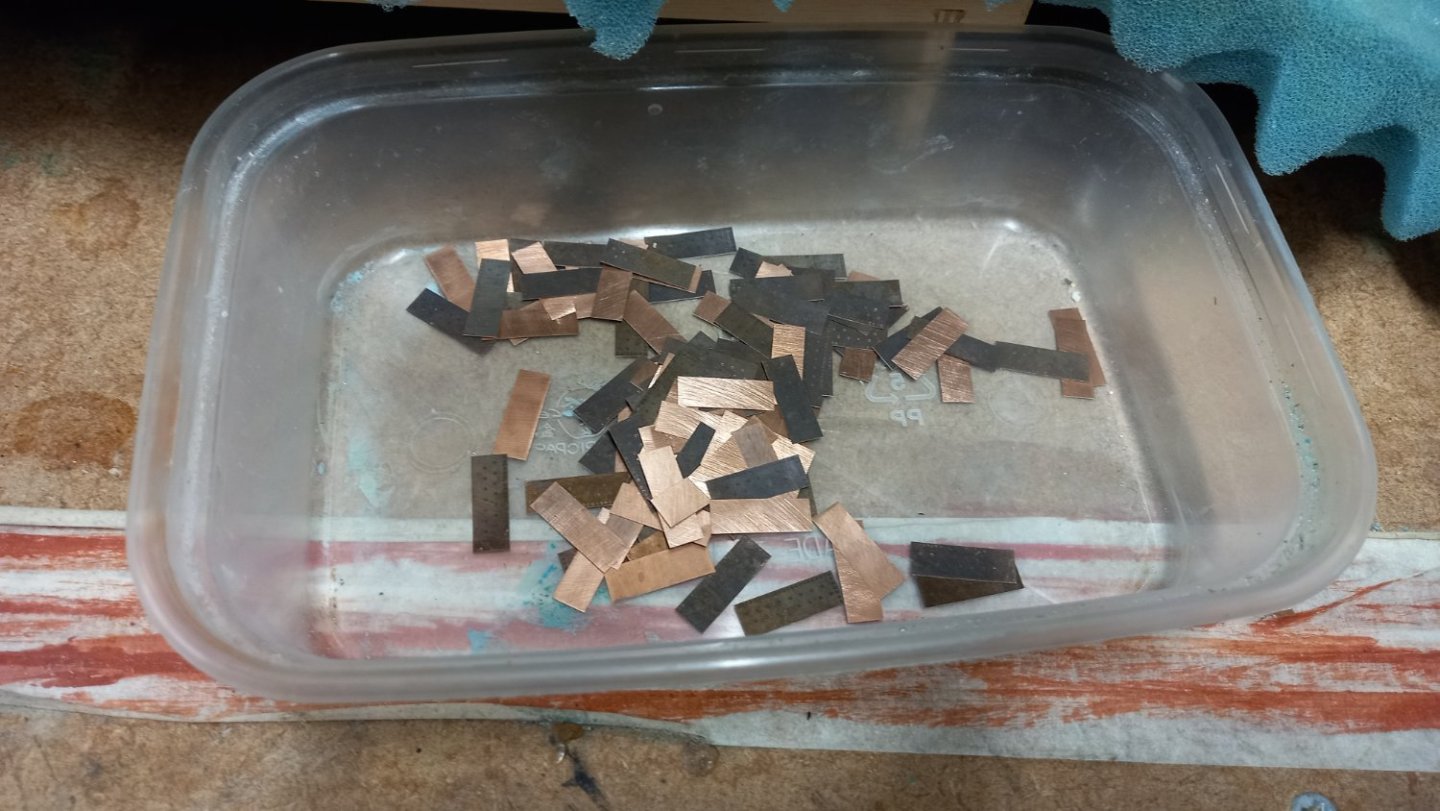
Imediately soaked in 1 part Miracle grow and 3 parts red wine vinegar for varying lengths of time between a few miniutes and a few hours then allowed to dry. The backs of the plates cleaned using fine sand paper
.thumb.jpg.d6f8e62ad7f65c023a6f3fd3b94a8346.jpg)
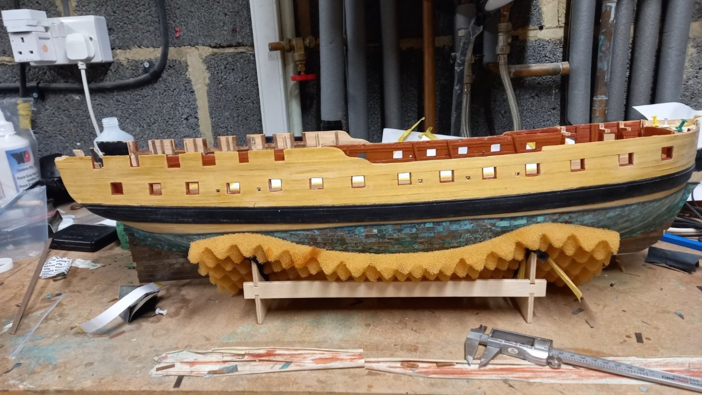
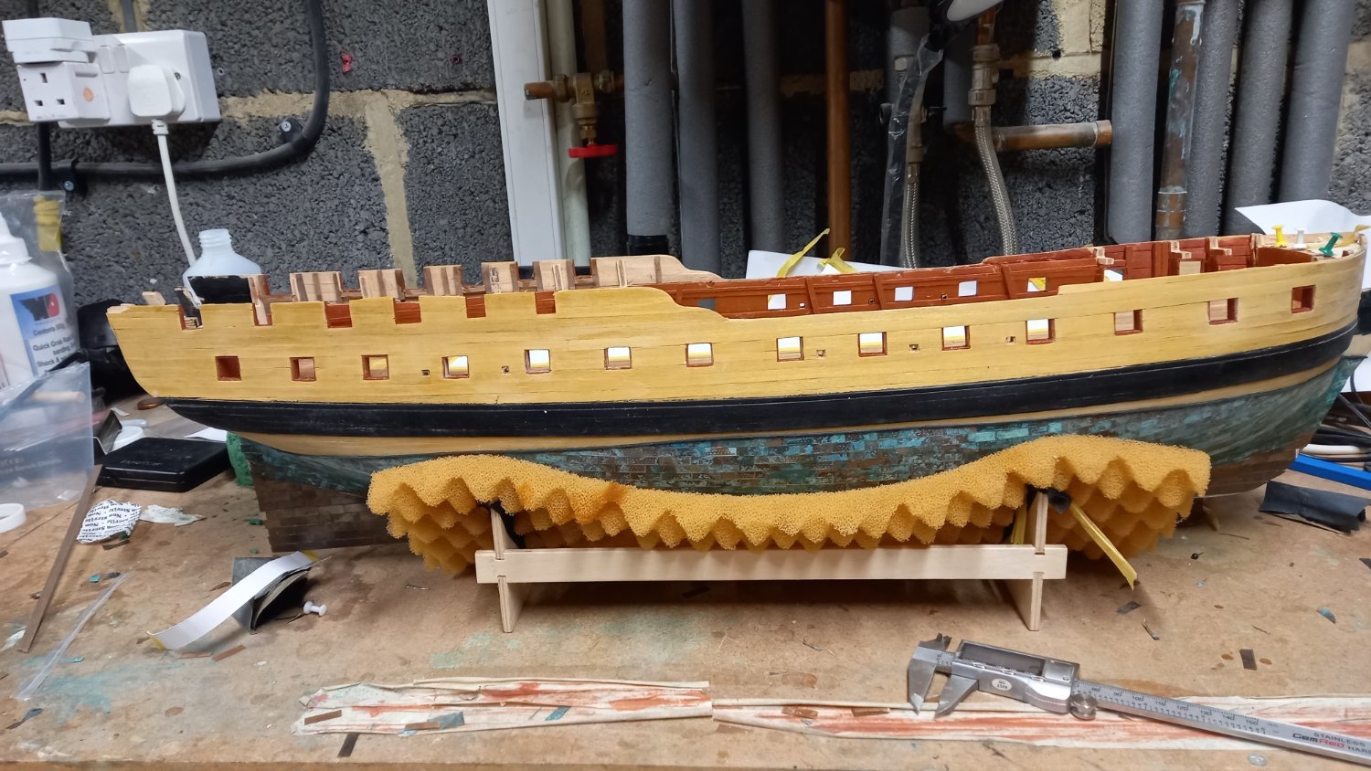
A few photographes of the progress.

YA
Just starting to show when vessel the riight way up.
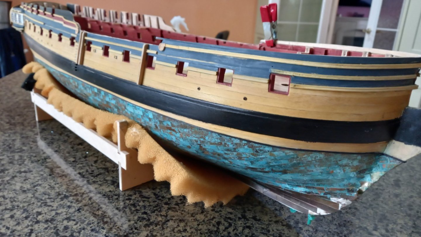
Perhaps not to everyones taste however I am fairly pleased in the way it has worked out for my first attempt at fitting copper plates. Fortunately with starting at the keel most of my mistakes are out of sight and by the time the hull is visable I was starting to get the hang of it. Hopefully I wil also be able to remove some of the super glue where the glue was squeezed out between some small gaps.
I am still hoping to blend the areas a bit better by adding a bit more patina to various places before finally sealing it all once I am happy with the result. Knowing when to stop might be key here..
-
1 hour ago, dunnock said:
Many thanks for your kind words Andrew.
I have been looking around a bit more and I think that you are right, the case will have to be at least 5mm thick acrylic. I priced a couple of custom-made cases and they are very expensive. I made a smaller case for HM Cutter Hunter but have never tackled on of the size need for DIana. I have completed a new stand so I now have the final case dimensions and will order some sheet next week.
David
A question if I may. Is the weight of perhaps the cheaper option of glass too heavy?
-
-
-
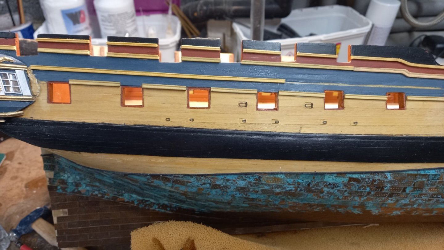
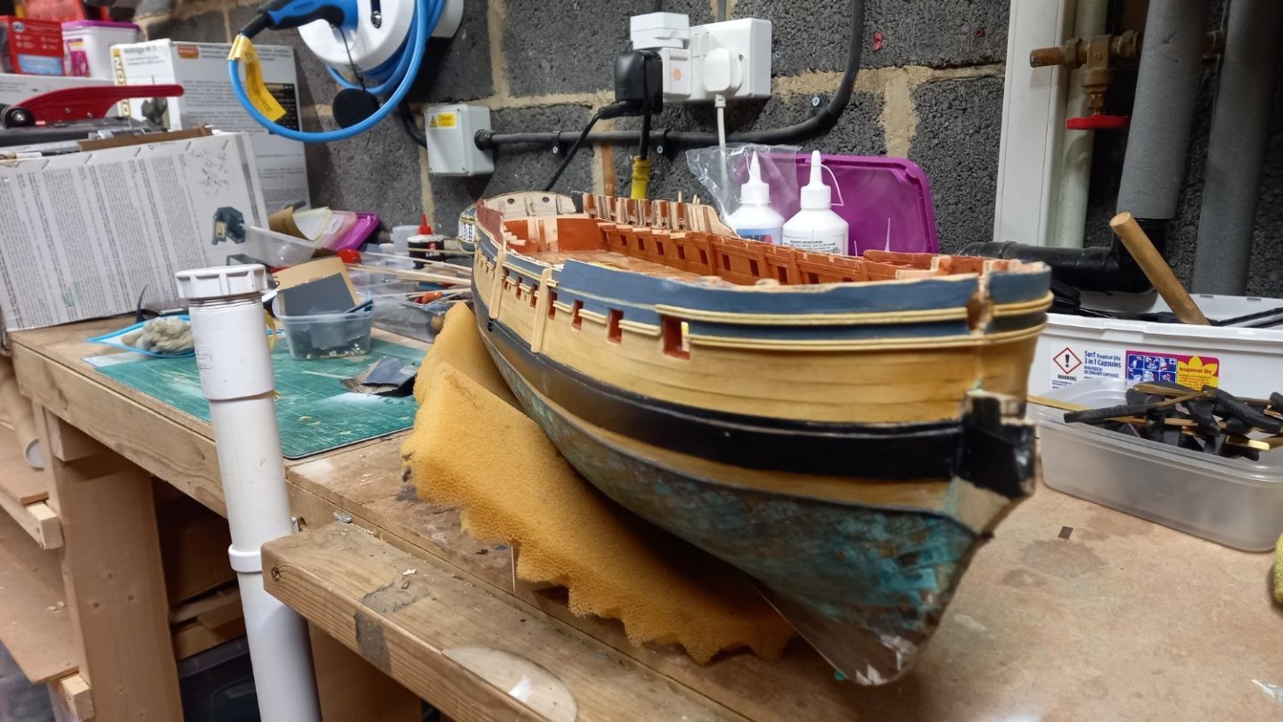
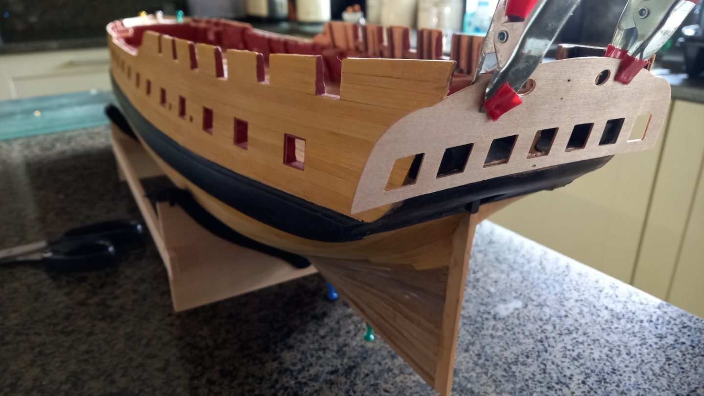
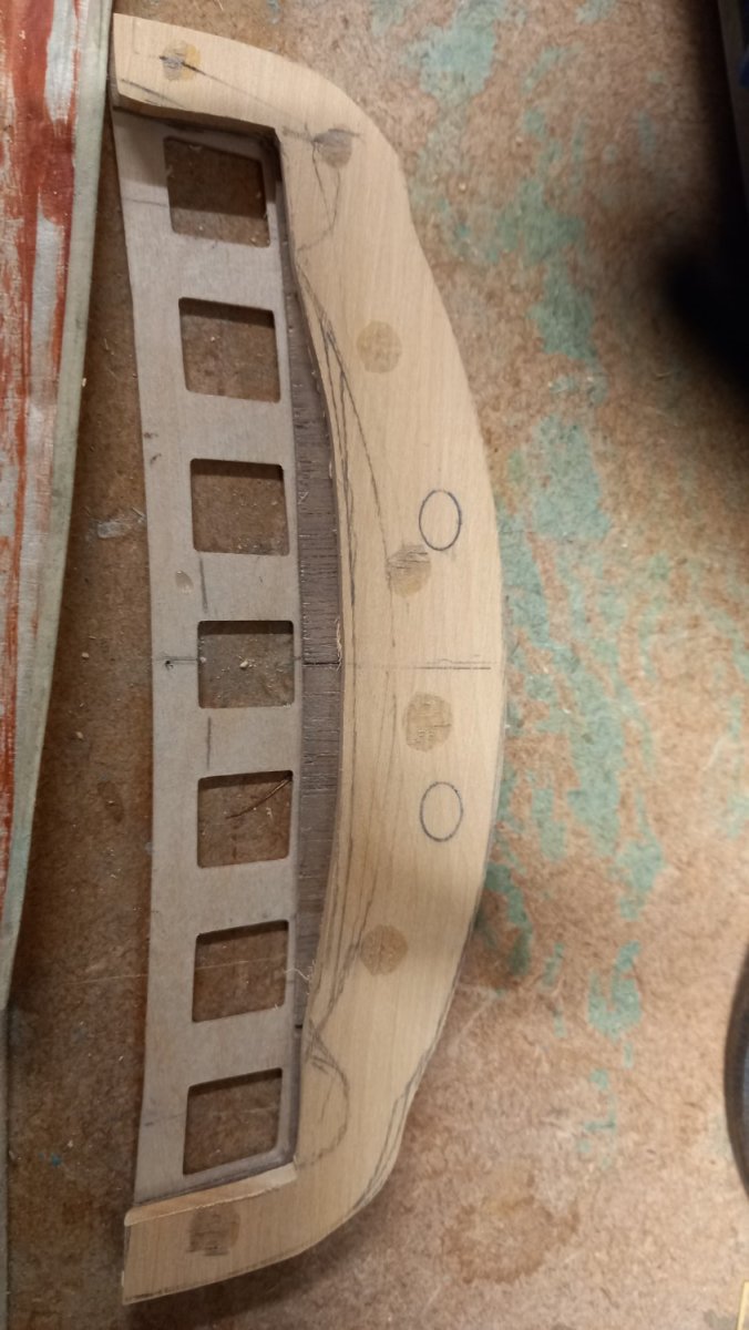
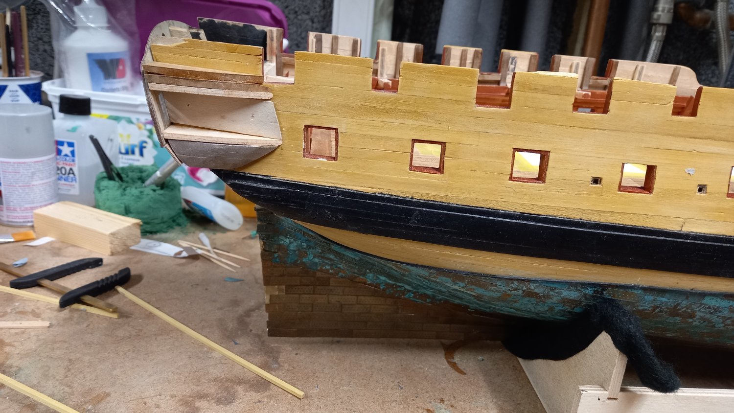
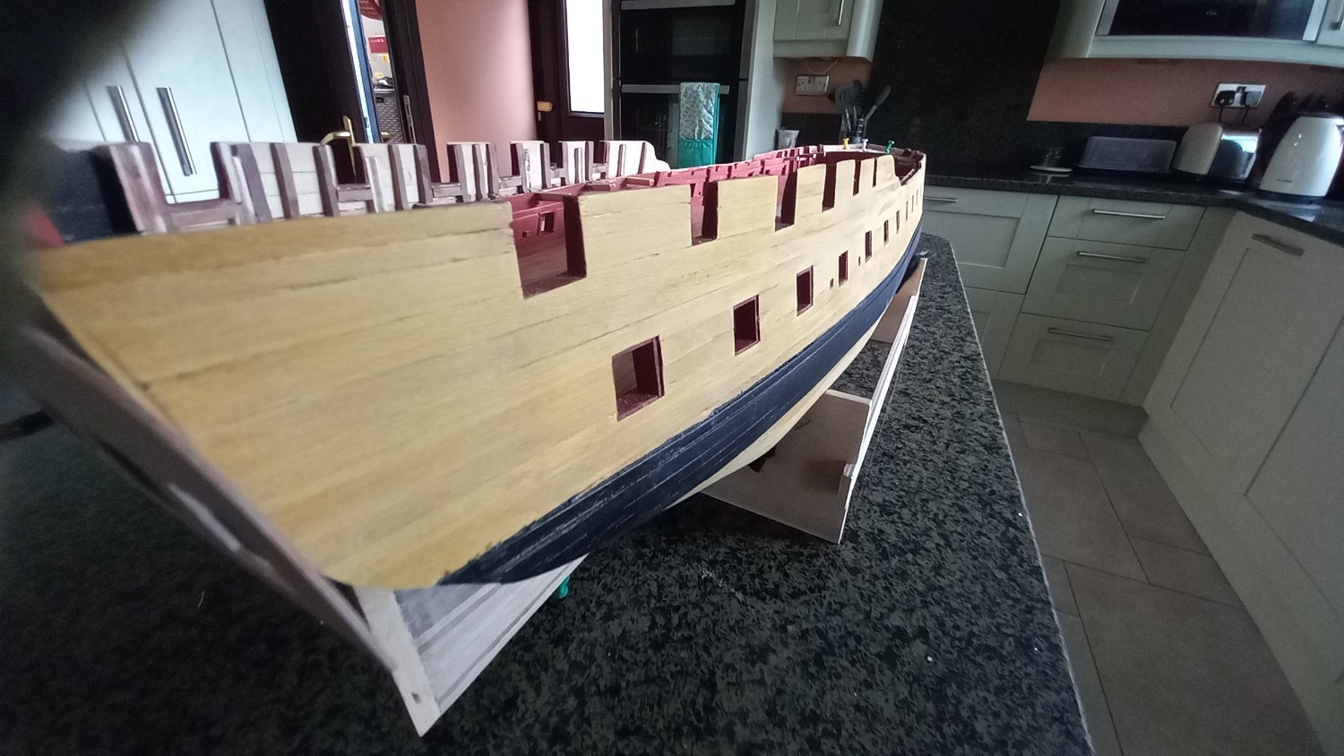
Finished off the second layer of planking and lined the gun ports. I still need to cut out the square sections for the ventilation scuttles and holes for the scuppers to complete the hull. Next up will be the fitting of the Quarter galleries and the stern gallery. I am still not 100% sure as to the correct position of the quarter galleries other than Jason suggestion of lining up the windows with the gun ports and the windows in the stern facia. I might even use some of the rails to see how these look when all is put together before gluing I will also probably try airbrushing the parts before assembly rather relying on masking tape to get clean edges.


- chris watton, ccoyle, allanyed and 5 others
-
8


.jpg.fbfa092011ce10c22f1e2aae0d6b3174.jpg)


.jpg.d1ccff543895e22a7e4c94704af615b0.jpg)


Pintle straps and what they are made of when fitting copper plates to the hull?
in Building, Framing, Planking and plating a ships hull and deck
Posted
I think I will give that a go. Thank you