

Sooty
-
Posts
76 -
Joined
-
Last visited
Content Type
Profiles
Forums
Gallery
Events
Posts posted by Sooty
-
-
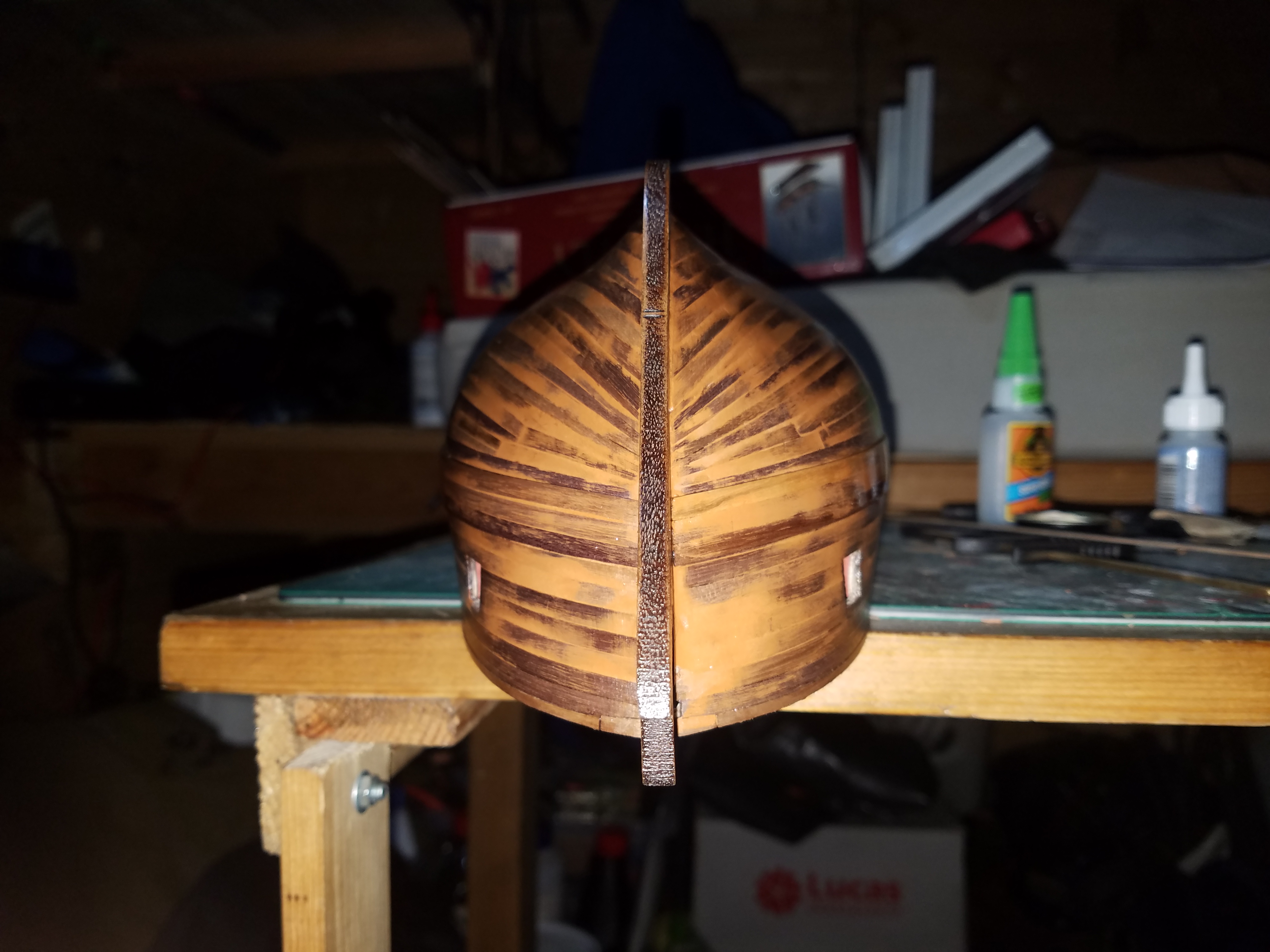
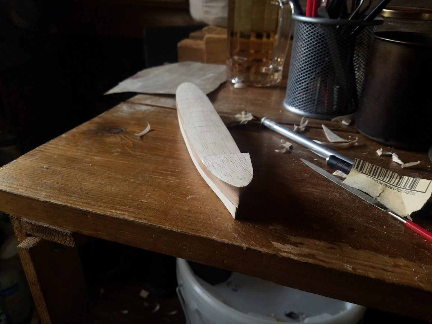
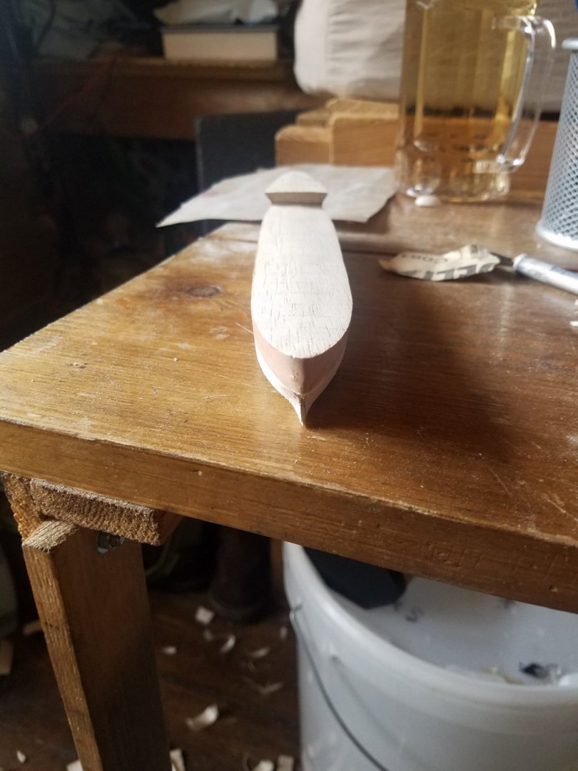
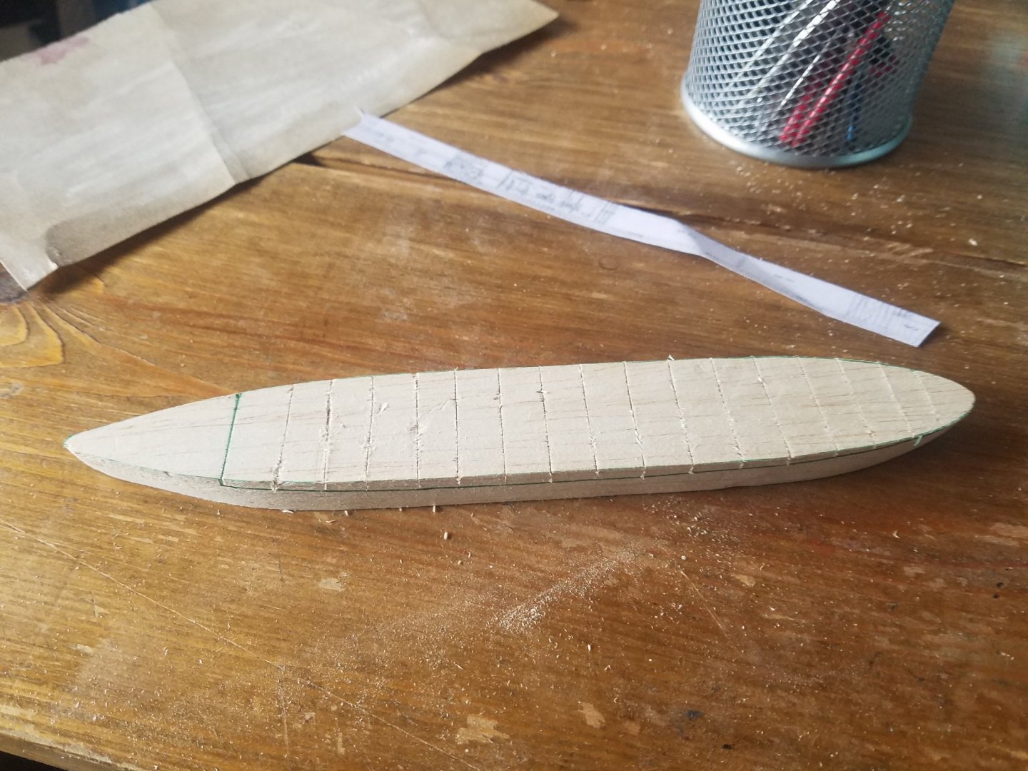
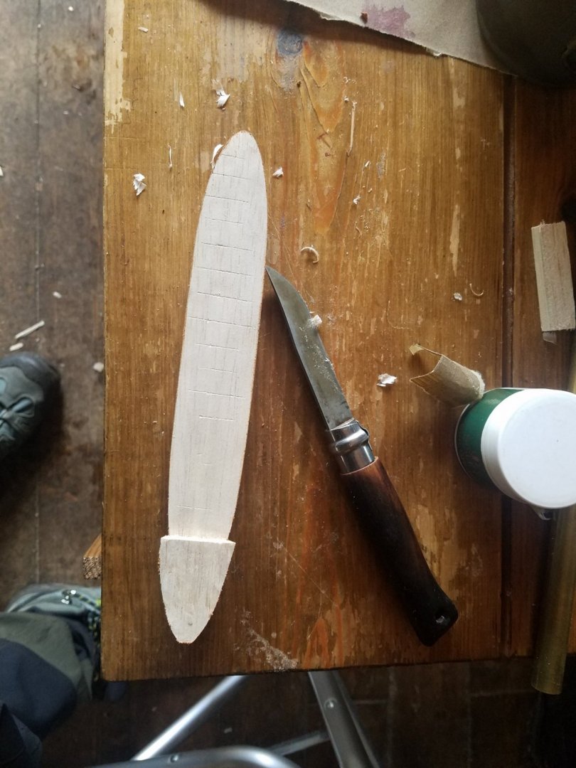
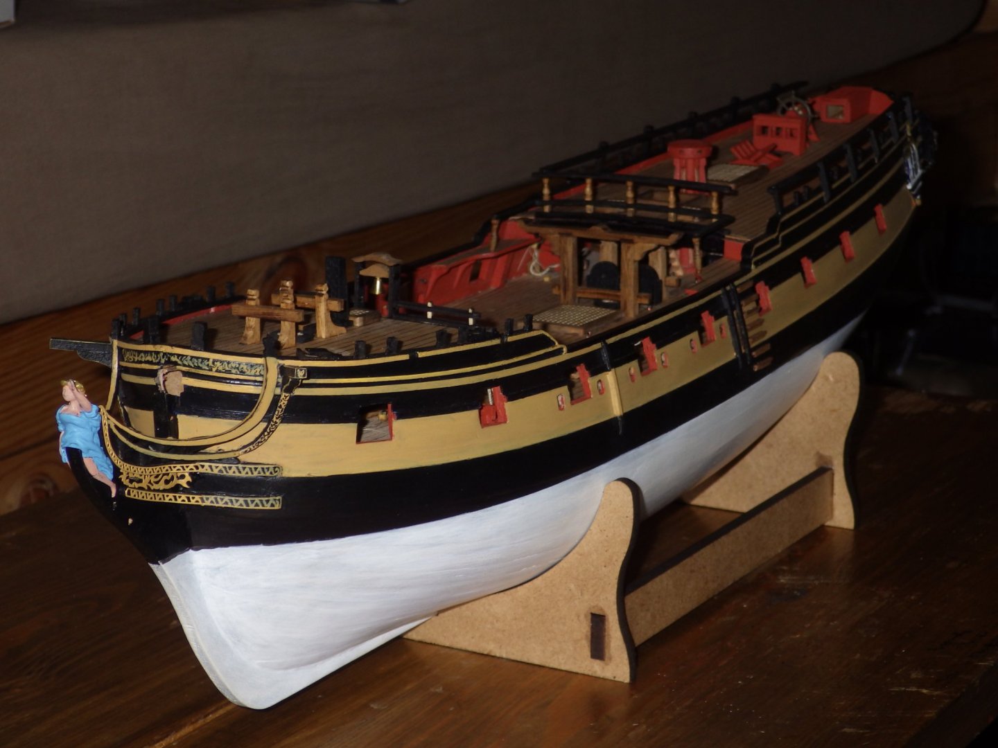
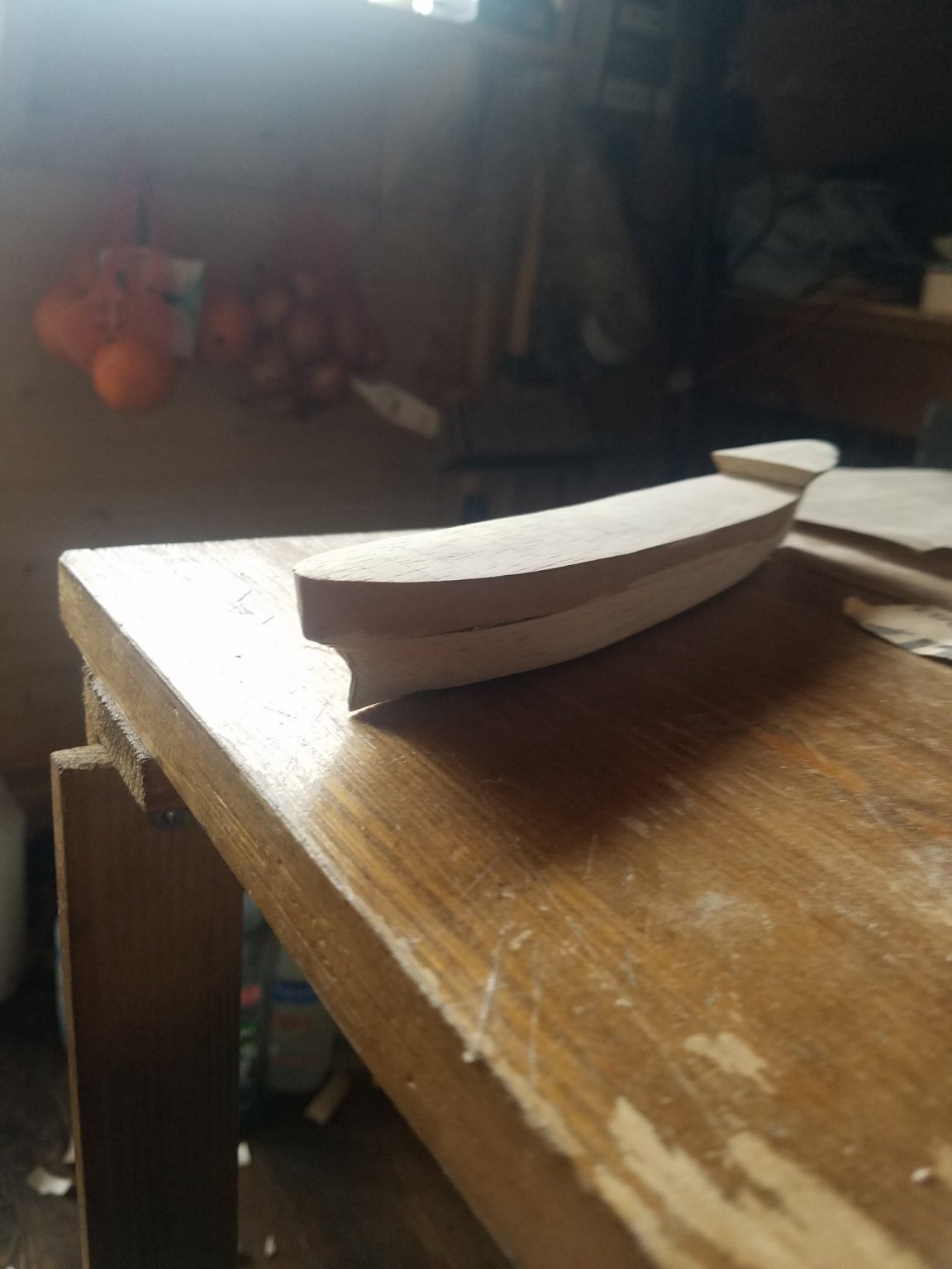
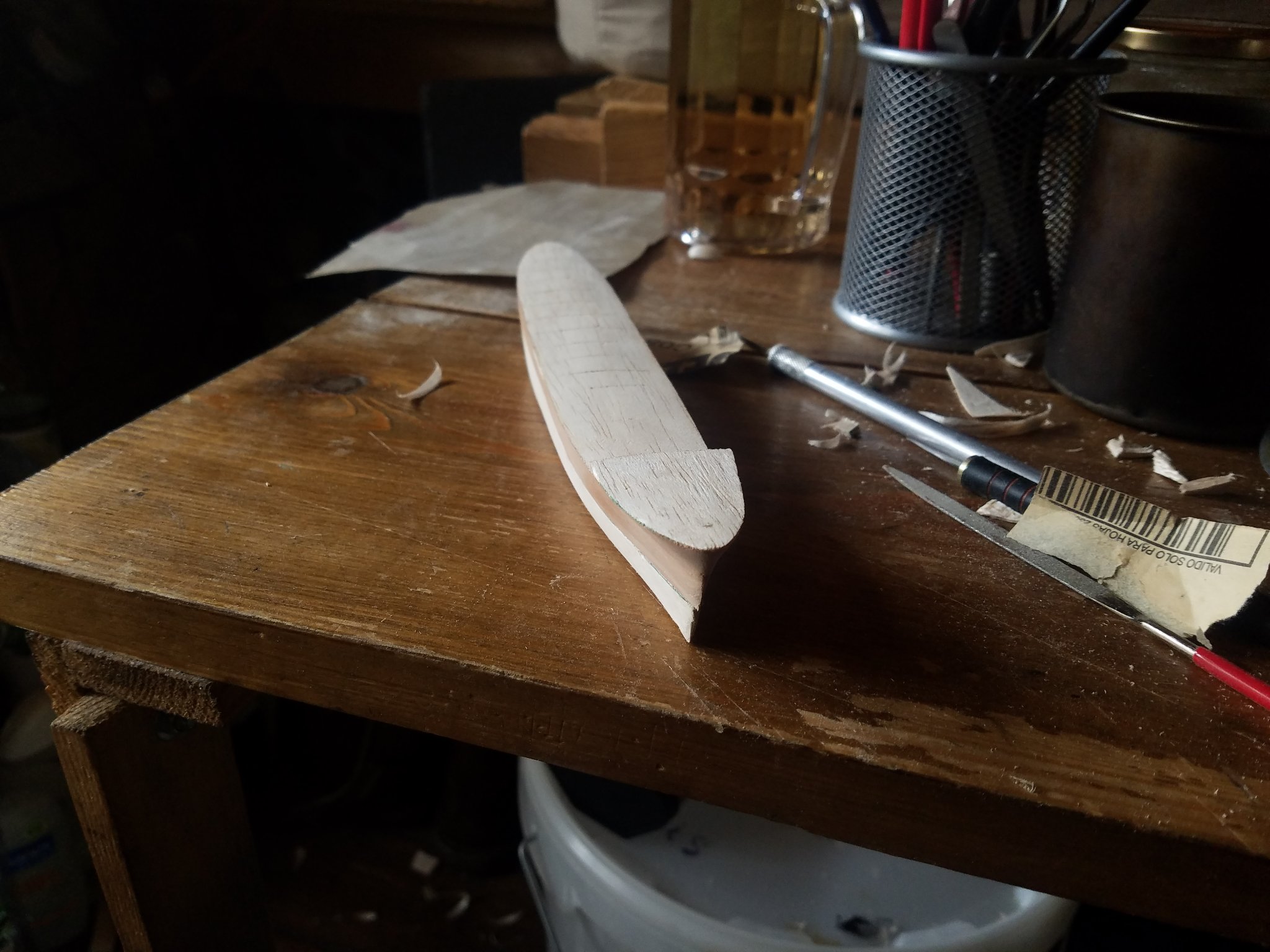
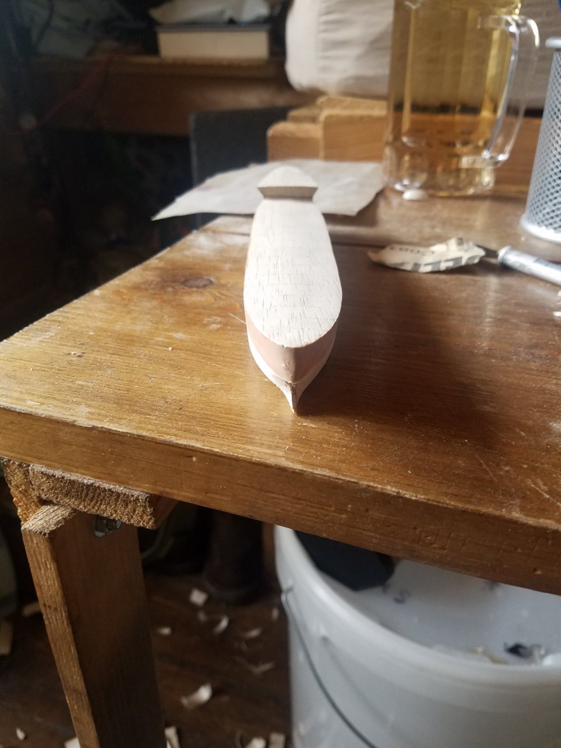
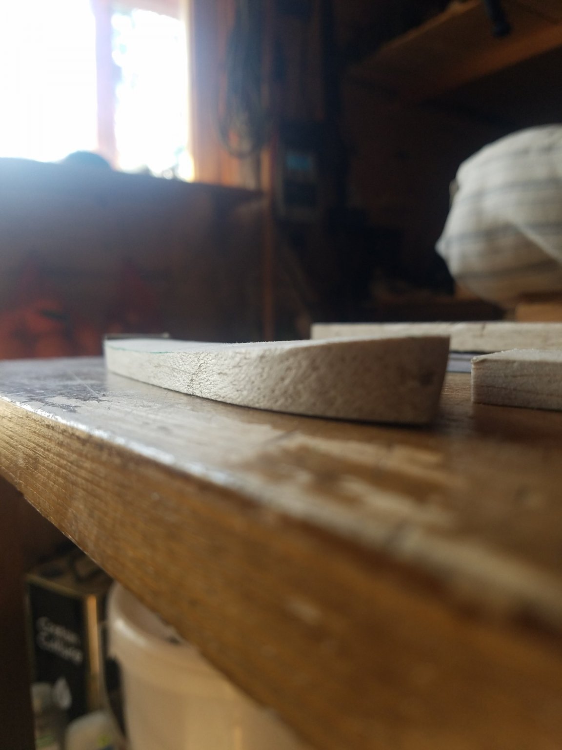
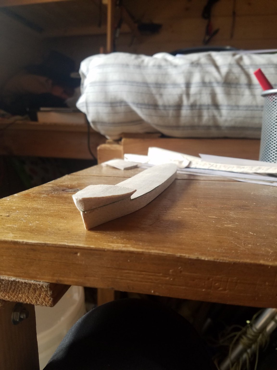
Today I decided to try the hull below the waterline, and see how it turns out.
It actually turned out great. I didn't bother with actual sections off the lines plan; instead, I just used a couple of profiles, sandpaper, files and my imagination (I am a Naval Architect by trade, so I can kind of visualise a hull off its lines plan). All balsa, but I split the lower half in two sides and I inserted a 'keel' cut off the profile, to help with the shaping.
The model will be on a 'sea' diorama, so I won't bother much more with the bottom of the hull.
Anyway! Enjoy the pics!

- Ras Ambrioso, Tony Hunt, Canute and 2 others
-
 5
5
-
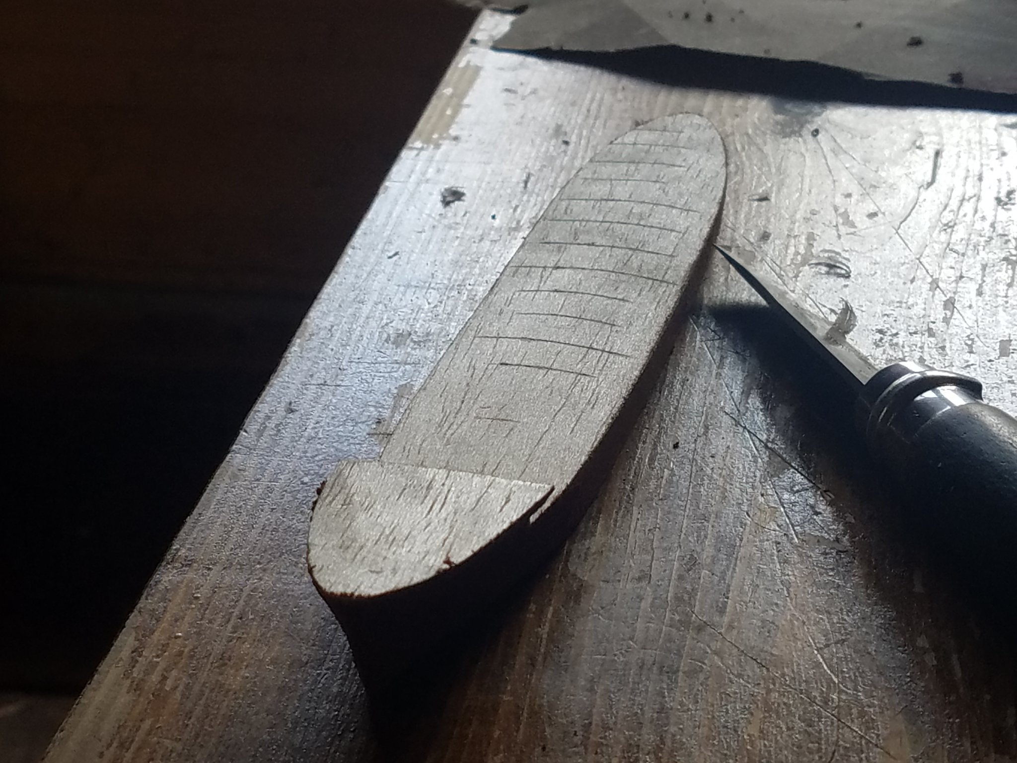
I always used a plane to taper the masts.
I taper the dowels down to the required dimensions, first square, then octagons, then I sand them down to a circle.
With a little practice, it is very hard to get this method wrong.
You do need a well set-up plane with a very sharp blade though, and it can get messy if there are irregularities in the wood.
- Meriadoc Brandybuck and TimC
-
1
-
 1
1
-
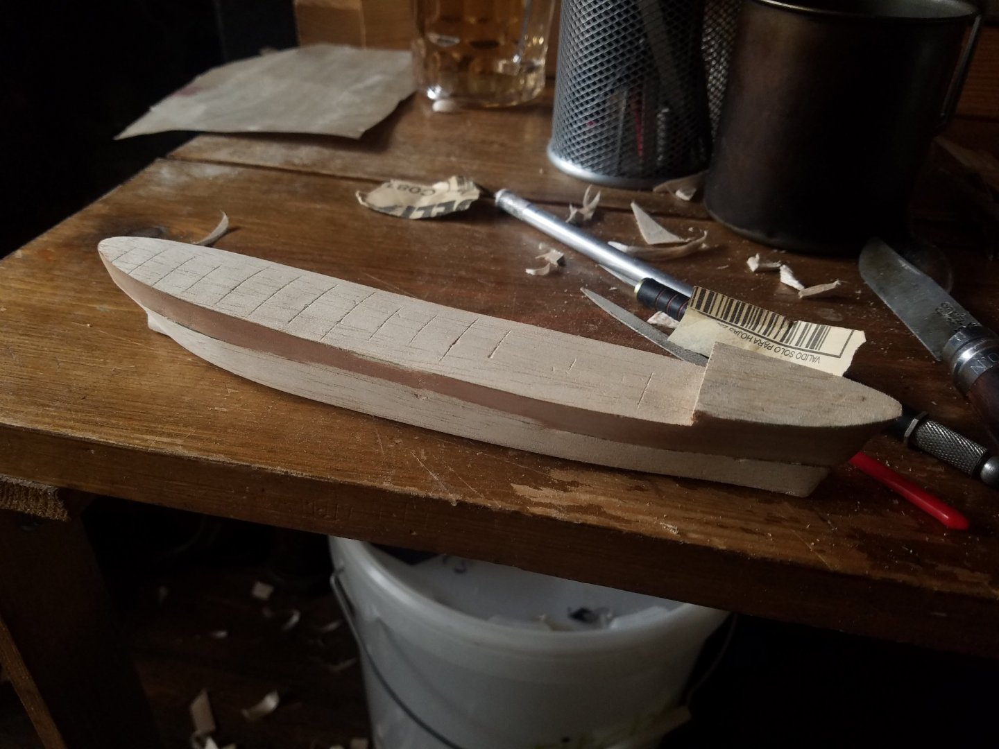
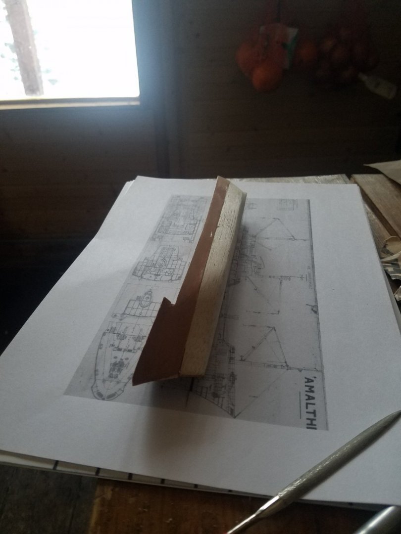
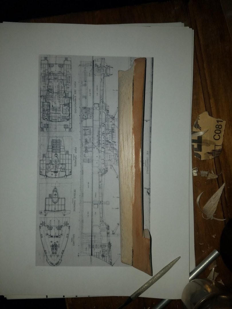
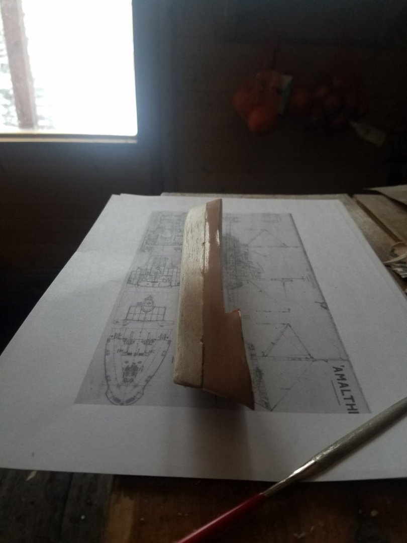
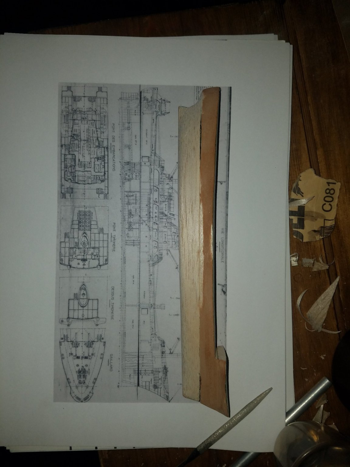
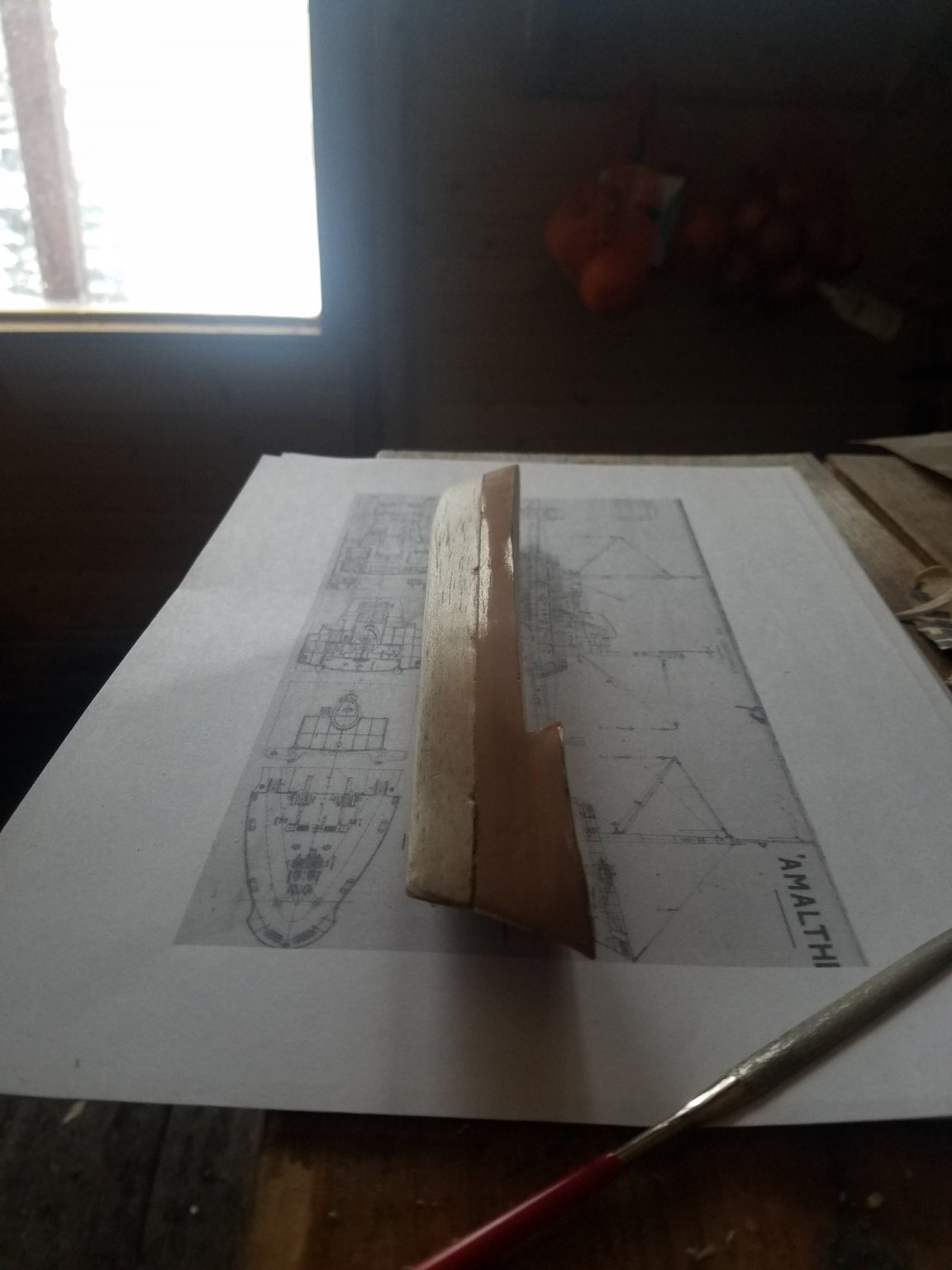
Just started this one, after managing to get my hands on the original yard drawing with the help of an incredibly helpful Frenchman.
This is a the build log of HS Evros (pennant number A415) of the Hellenoc (i.e. Greek) Navy. Hull and the major parts made of balsa, with some styrene sheets, copper tubing, stretched sprue, and leftover PE bits from previous builds of Liberty ships and destroyers.
The ship started life in the mid 50s as 'Amalthée' (sister ships Enée and Borée), before being purchased by the West German Navy and used as an ammunition ship from the mid 60s till the mid 70s. She was then transfered to the Greeks, where she served till 2009. She spent the 2009-2020 period laid up in Souda Bay, with plenty of photos of her.
My dad was her skipper for a couple of years in the mid 80s. Believe it or not, I went on a 3 day trip on her as an 8yo... different days, and I guess nobody would question the skipper 😂
I had a look to see if I could find any good photos of the boat. I was saddened to see that she was used as a missile & torpedo target in the summer of 2020. At least she now rests at sea, where she belongs.
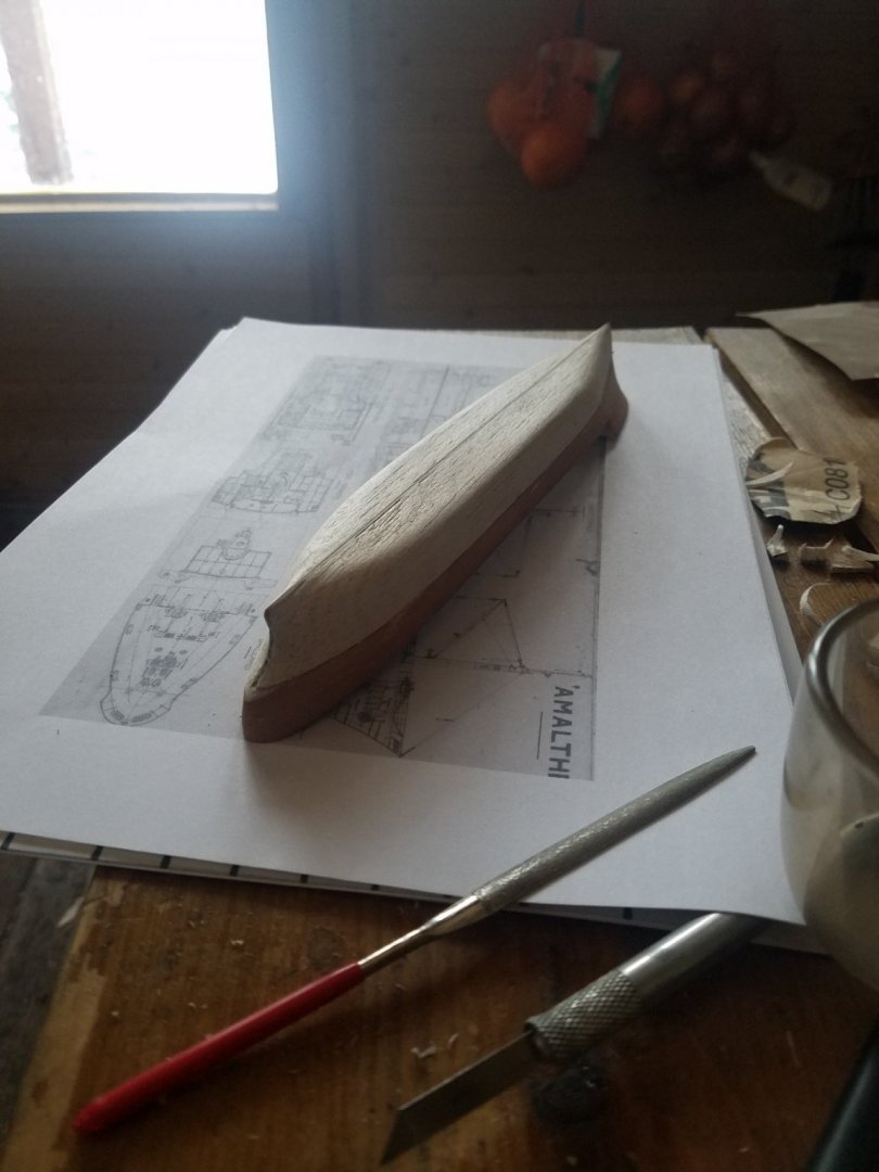
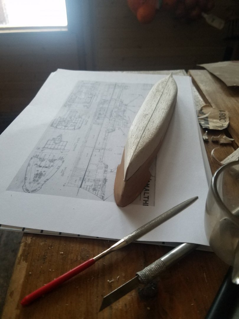
I decided to build the model with minimal references. While searching, I got in touch with a Frenchman who happened to know where I could find the original yard drawings. I will post the links later, as there are many mamy more drawings of other ships.
Anyway, enjoy!
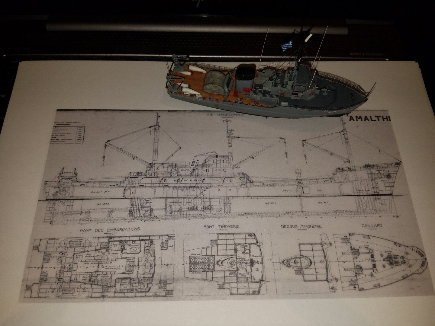
The general arrangement plans, printed to 1:350, with a minesweeper for reference. LoA 80m.


- Roger Pellett, GrandpaPhil, ccoyle and 1 other
-
4
-
9 hours ago, TimC said:
Was wondering where you’ve been! Best of luck with the move
Tim
It is likely to be July before my Fly can get outside to play again! I can of course keep building all the little pieces and finish the hull and the masts, then just wait till I am settled in before I install them and rig them up. Meantime, I will be watching your build!
-
I've been very quiet 😂
I have not lost my modelling mojo, nor have I pressed on with the build and not posted about it. Just a major geographical move now being firmly on the cards, so I think it is best to leave the masts off the boat till she is her new (forever) home! All going well, there will be a mantlepiece over a fireplace!
-
Hey, great to see you starting it!
Regarding showing a waterline but not losing the wood texture, how about a subtly darker shade of stain for the underwater parts? I have no idea how it will look though!
-
Your first planking is absolutely gorgeous. Keen to see how your build will progress!
-
1 hour ago, Lieste said:
The 24lb Vasa cannon (a light piece, half the weight of the gun of the period, or of Napoleonic era pieces) was tested at 360m/s using powder 'suitable in quantity and quality' for artillery of the early C17th)
For late age of sail period gunnery and the 32lb gun of 55cwt:
Distant charge gives approximately 1489 fps or 454m/s (according to available numbers for dimensions, plus the estimated internal ballistics from "Aide Memoire d'Artillerie Navale"), this is sufficient to drive the ordnance alone backwards at 3.83m/s (using the augmented recoil according to AMAN), which is immediately moderated by an impulsive transfer to the carriage to 3m/s, with 4.46kJ absorbed from the original 20.68 kJ, leaving 16.22 kJ to be absorbed by friction and breeching.
I neglected side tackle, but can consider what they might provide in a follow up calculation, but did allow for the 0.1 mu at the trucks, which might already factor in some part of that requirement - and assumed that the muzzle after recoil would be brought to the position of the trunnion when run out.
With the friction alone recoil at the 'stop' still had 5kJ to absorb into the breeching, with a 'free recoil' length of 15.7 ft if not restrained. (or 3.5 times the recoil distance selected).
Reduced charges give lower recoil with single shots, but double shot with the middling charge is significantly sharper. ~1000 fps for top shot, and ~800 for the second (though admittedly this should be considered a much more tentative estimate) with this giving a 4.43 m/s initial recoil of the bare gun, 3.47m/s after taking up the carriage - with 6kJ nearly being lost from an initial 27.66kJ - recoil energy remaining at the selected recoil distance increases to 6.68kJ and free recoil to 20ft.
Smaller bore guns are much heavier, for their shot and the longer, heavier small bore guns (e.g. the 8.5ft 6lb will only free recoil around 3 ft with the same assumptions, compared to 4.3ft for the lighter, shorter 6ft gun).
Carronades are significantly sharper than guns in recoil, despite their lower performance.It sounds like I was completely off with my assumptions 😂
Thank you for the velocities, with over 2x what I had assumed, it now makes sense that the breeching line would take a serious beating on every shot!
-
-
2 hours ago, TimC said:
What is a messenger rope? Is that the smaller pieces of line they use to guide the larger ropes?
The anchor cable had to be very thick to be able to take all the mooring forces, so you probably couldn't put too many turns over a capstan with it. Also, you probably wouldn't want to do that anyway, as it would mean running the cable all the way to the capstan, then to the hold. And -probably the main reason- you would never be able to handle the cable over the stoppers if it was under tension.
Instead, they used to run a 'loop' of smaller diameter rope called a 'messenger', looped 3-4 turns over the capstan (for friction) and over to the bow (over a couple of rollers just in front of the manger boards).
That piece of rope would run right next to the anchor cable, and it could be tied onto it along several spots to 'connect' the two ropes. You would turn the capstan, keep adding ties along the two ropes as they met, and remove them as the anchor cable was approaching the hole down to the holds.
That way, the anchor cable was under no tension once past those ties, so you could handle it easily, turn it over the stoppers etc.
I'll try and find a sketch for you, as it would probably explain it much better!
-
53 minutes ago, Meriadoc Brandybuck said:
I have done some reading over the years and shabbily put together a few plastic kits- that is all. My first wooden kit is in the mail as we speak and while I wait for it I'm poking around these build logs and finding out more invaluable insight than I ever thought one site might hold. Its fun to see how different people build the Fly, for instance. So many ideas..
Oooooh! What did you get??
-
1 hour ago, TimC said:
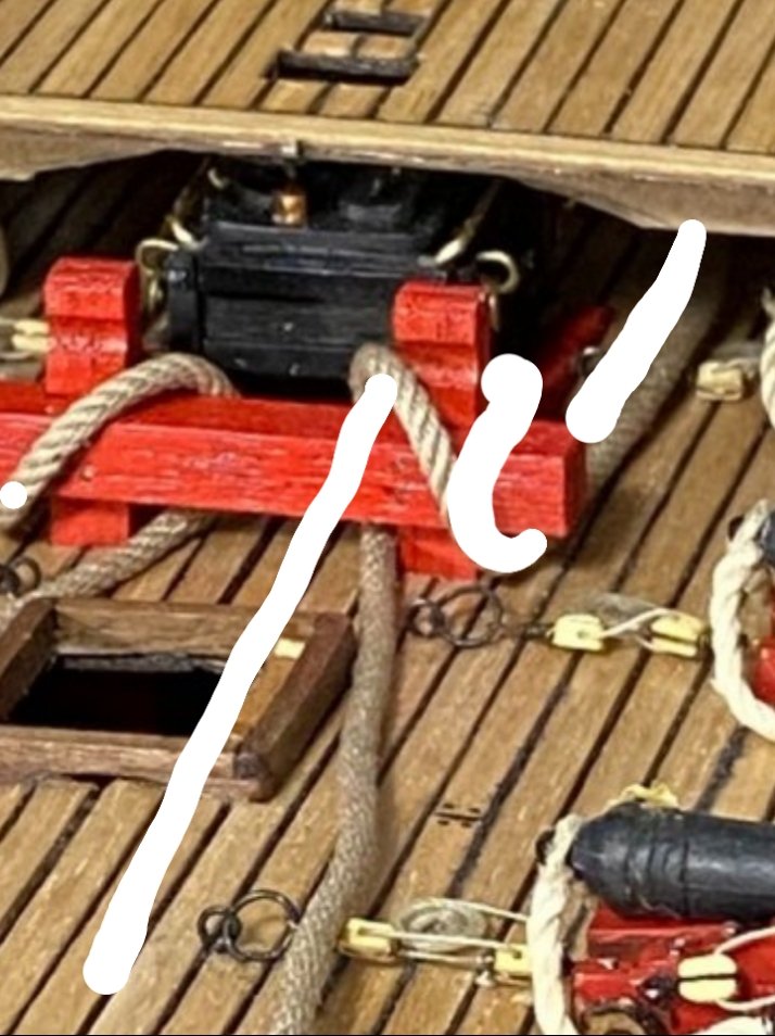
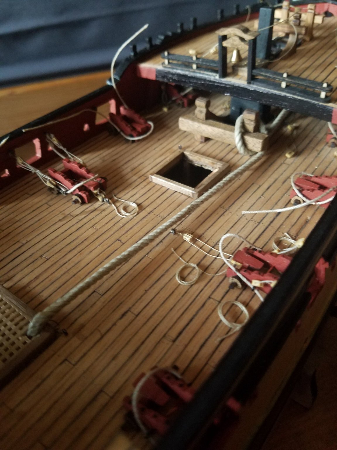
Thank you Sooty! And I believe you’re right about wrapping differently. I’ll need to do some more research on this for sure,but your reasoning makes sense. I also need to figure out where to have the ropes go...I didn’t think to make an opening in the gratings at the mid ship so I may just add portals for the rope to terminate through the deck just in front of the grates. Might not be accurate but it’ll be functional!
tim
I just drilled and filed off 1 square off the mid-ship hatch's grating, at the two fore corners. I will fill and stain the adjacent parts of the gratinf, to make it look like it's not part of the grating but a fixed part of the hatch coaming, and have the rope pass through the hole.
It LOOKS like this is the way to go, but still not 100% sure. It appears that this is what it would be for weighing anyway, but I want to show it like it is about to be lowered, which could be different.

I realised I should have installed the messenger rope a long time ago. This could be interesting 😂
-
38 minutes ago, Meriadoc Brandybuck said:
I think the cable would run outside the bits and wrap up inside the top and ride against the indent. Must be a reason to have an indent there, I guess.
I can refer you to the Heller HMS Victory build by Dafi, where he goes into unbelievable detail to show the weighing process (but not the dropping process if I recall). It starts on page 5 and continues to page 6 and possibly further. His build log is a really good place to go for ideas or entertainment, and might be able to answer your questions.
Link:
Crikey, that really is SOME build! Thanks for the tip!
-
31 minutes ago, Meriadoc Brandybuck said:
The ropes that hold the bowsprit down are called the gammoning. I say this not to correct anyone or sound like a know-it-all, but I figured having the correct term around would make it easier to talk about.
On heads- idk how many Fly had or where they were on ships this size but traditionally they should be on the beakhead grating. For smaller ships with no such grating, I don't know what arrangements were made, though as you say OSHA really had very little influence in those days. There is a motivation for putting them in the front of the ship though and it's the same as why you put the stove up front (forgive me if you know this already): anything smelly or smoky should go forrard where the wind can take it away as fast as possible.
It all makes sense, as those were boats which primarily sailed downwind or on a reach at best, e.g. the wind would always be away from the bow, unless riding on the anchor.
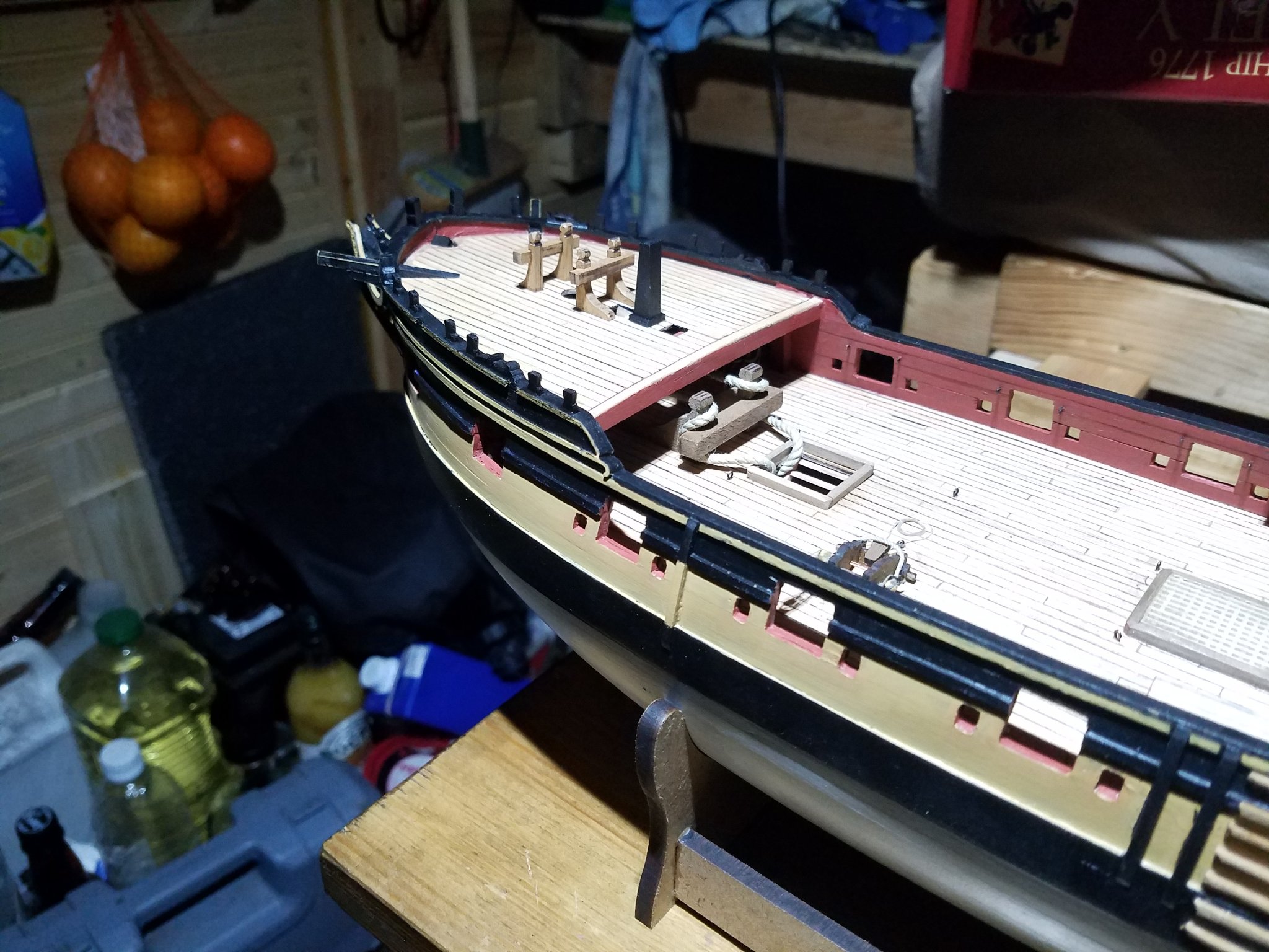
Speaking of anchors, any idea how the anchor cable would normally be riding over/around the stopper bits, when the anchor was secured for sailing? I am planning to set up the ship to look like she has just arrived somewhere; one anchor stowed, one anchor hanging from the cathead ready for lowering, the ship's boat being lowered and all but a couple of sails furled.
I am confused as to how the cable would run for the stowed anchor and this is what I had in mind;

-
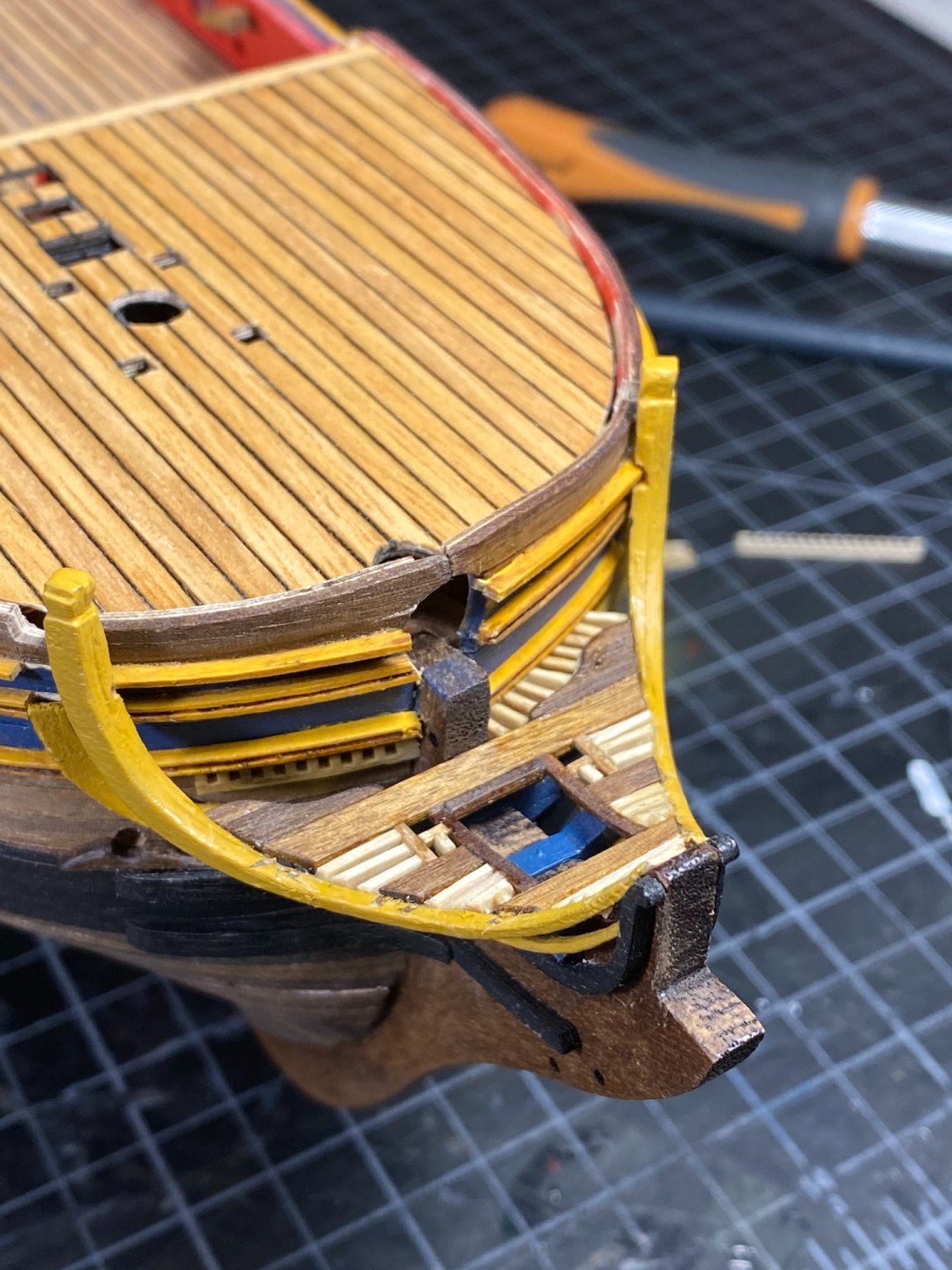
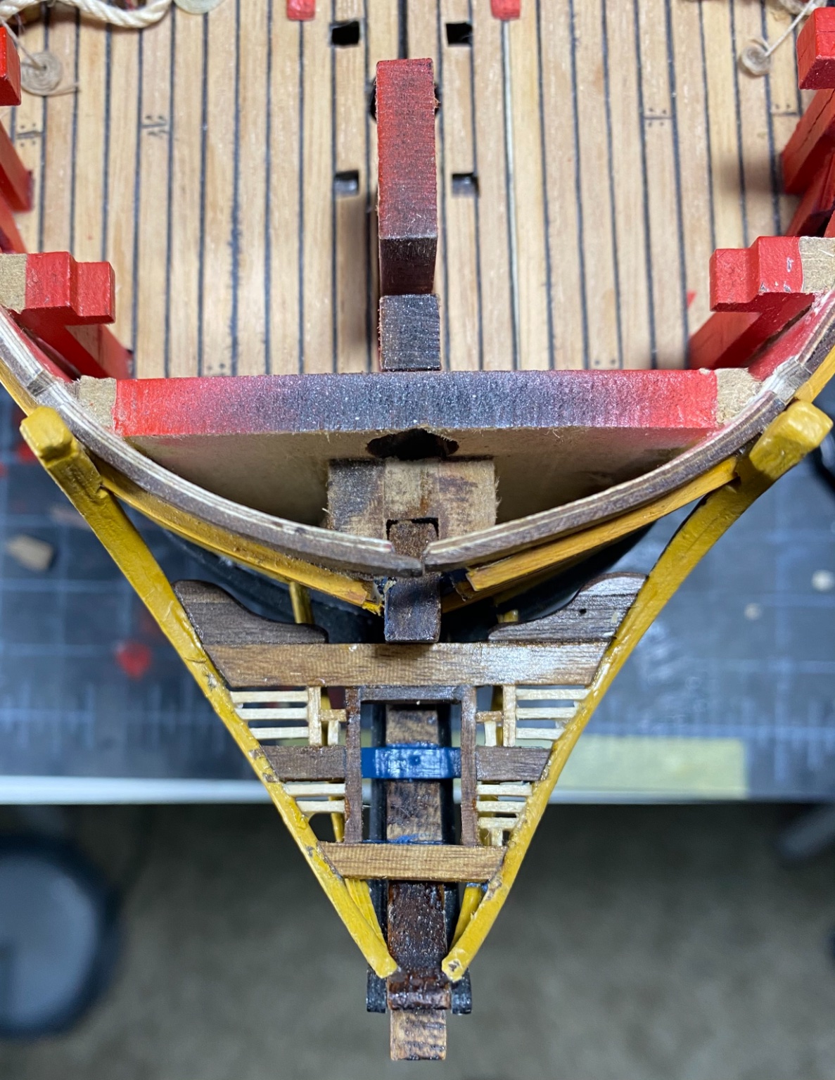
Hello Tim, great job, the bow platform is looking good! I am still figuring out how to do mine.
On the anchor cables; I think we need to ask for help. I took mine out as I wasn't sure about how I had them going over the stoppers. I am not 100% sure, but you may also have them in a wrong way; the cable should be able to run along the deck, I think on the outside of the stoppers.
When placed over the stoppers, I think it should look like this;
My reasoning is that -by being on the outside of the bits- it would allow it as straight and long a run towards the capstan as possible, for the messenger rope to hold it.
Again, I am not 100% on this one, and I am stuck with the same issue 😂
Anyone knows for sure?
-
11 minutes ago, TimC said:
Glad you find it helpful!
I understand very little on the history of ships....I more love the beauty and the art aspect of them, but I’m becoming more and more interested in getting things historically accurate. My first boat I’m using to learn the process as much as possible then I’ll get more concerned with period related accuracies on my end. Seems like you know a fair bit on the history
as far as the heads, You may be right but I doubt OSHA had a ton of pull back then 🤣😂
That is all related to my problem 😂 I am a Naval Architect by trade, a keen sailor, worked onboard ships for a bit in my earlier years and now work with the oil&gas industry (a pretty risk-conscious sector), so it is hard to lose all the preconceptions I come with regarding risk assessments, the 'How I would do it' and all the expectations I would have from a modern ship 😂 I kind of need to unlearn everything and resist the temptation to do it my way 🤣
-
1 hour ago, TimC said:
I used the word grating but I’m not doing the grating as it appears on other parts of the ship. I think that would be too small to make with my current tools. I modeled mine off of work by BE and DFel and their build logs. It’s a time consuming process but I think it adds a completeness look to the bow. I’m not quite finished yet but here’s where I am so far
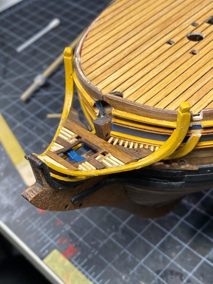


I used spare pieces from the grating on the hull part of the bow for even spacing. I decided to use walnut on the cross beams because I wanted a little contrast against the lighter wood. I believe there is a netting or a rail of some sort that should be on the sides but I’m not sure if I will be placing that yet. And I have to work out the position of the boomkins(?) before any of that anyway
your template looks good! I can’t see because of the angle but I took care to make sure the ropes that would attach to the bow sprite would be able to pass freely
Looking forward to seeing more
tim
That's brilliant Tim, thanks for the photos, good to see it without any clutter around it! I will probably do something similar then.
Still not 100% convinced the heads would be there, as I still think it is too low down to be safe for all the crew visiting a couple of times a day in anything but relatively calm weather. Then again, those were different times and men were being sent 100ft up rope ladders and yards of a rolling and pitching ship with no fall protection 😂
-
38 minutes ago, Meriadoc Brandybuck said:
I think even smaller ships like the Fly would definitely have a grating at the bow as there are some dealings with the rigging to be accessed here and moreover it's where the heads are.. Quite a busy place, actually. Wouldn't want the men to get washed away in rough seas while they try to relieve themselves with no platform to hold the heads they're supposed to sit on, as trained seamen are so hard to replace!
In Dafi's novel-length Heller Victory build log he estimated that on a first rate, the heads would likely be busy all the time given the number of men. I don't know how many heads are on a Swan class sloop but there would be around 124 potential customers at any given time, assuming the captain got his own astern. Quite an interesting logistical study that helps one understand a bit more of life in Nelson's navy, no?
I'm quite impressed by the look you're achieving so far!
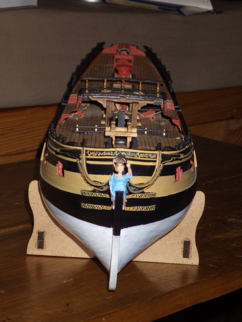
Grating it is then! I take it there would also be some sort of railings, some way of getting down there from the bow's bulwark, and of course the heads! It would be a tight squeeze for the heads' 'products'to clear anchor cables and the cheeks, so I wonder where they were placed. Probably just inboard of the grating's outer edge.
Just as well I will be doing this, as I was itching to do something other than the guns... I left the exposed ones (and -crucially- their rigging) till now, so it is an absolute headache to do them; 4h for 2 of them, and I think I did a sloppy job 😱
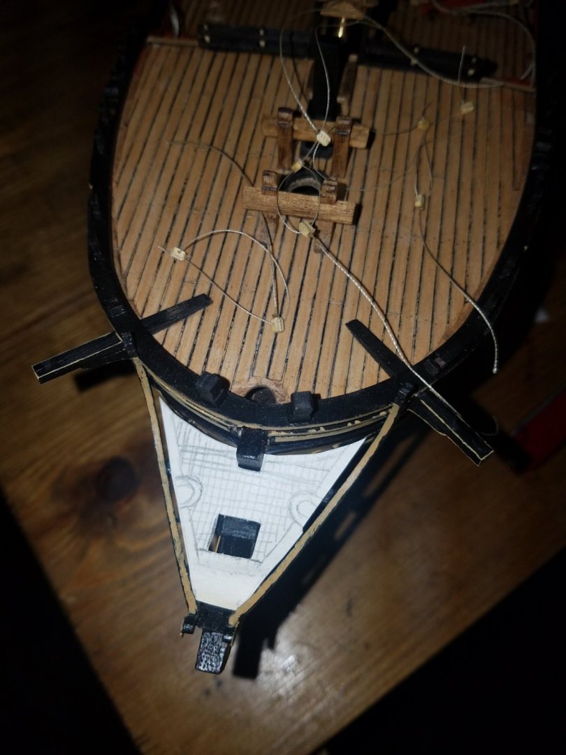
PS, I made a quick template. Does this make sense? Relatively flat, hole for the hold-down rigging for the bowsprit, one head either side along the outboard edge (to clear the boat on the way down). My main question here is how would men get up from /down to there? Also, this being such a small boat, most of the time the bows would be pretty wet. On bigger ships, the 'heads' would be much higher, so I wonder if the heads on these were somewhere else?
-
1 hour ago, TimC said:
Really looking good. You did a great job painting the bow decorations. Took me a few glances to tell what was PE
Keep up the good work!! I’m currently putting grating along the bow section. Talk about a test of patience
tim
You mean grating over a curve? 😨 That would be a tough one and Interesting to see, keen to see pics on your blog!
I opted on not grating the bow on the basis that it would be a small area with not much access or much to do there, so I assumed there would not be a platform.
I did have a good go at painting decorations. For the next build, I think I will find pens of the right colour and try working with them. I think there are very fine tip pens with gold ink.
-
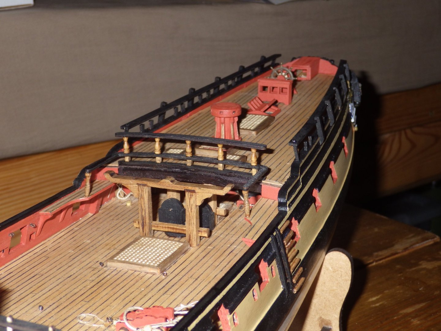
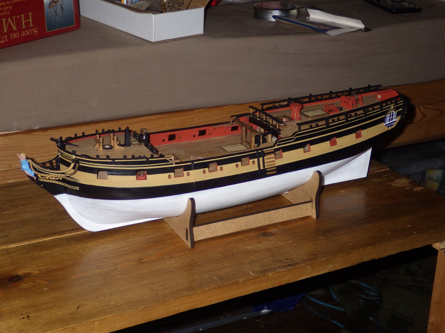
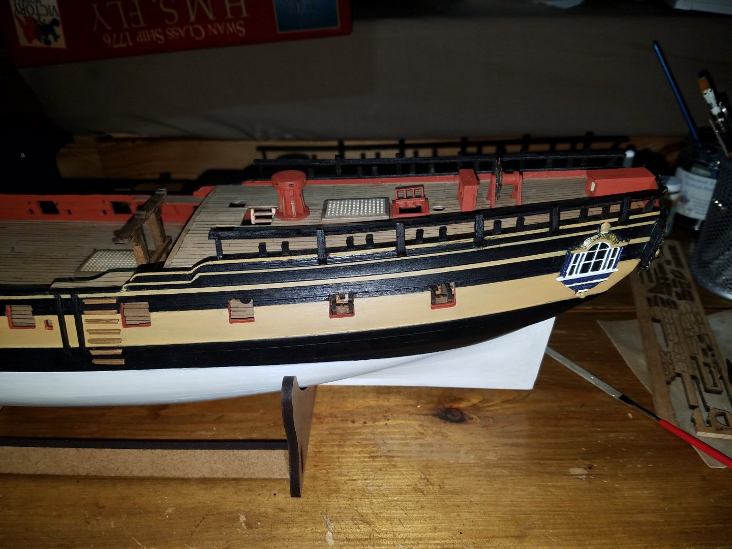
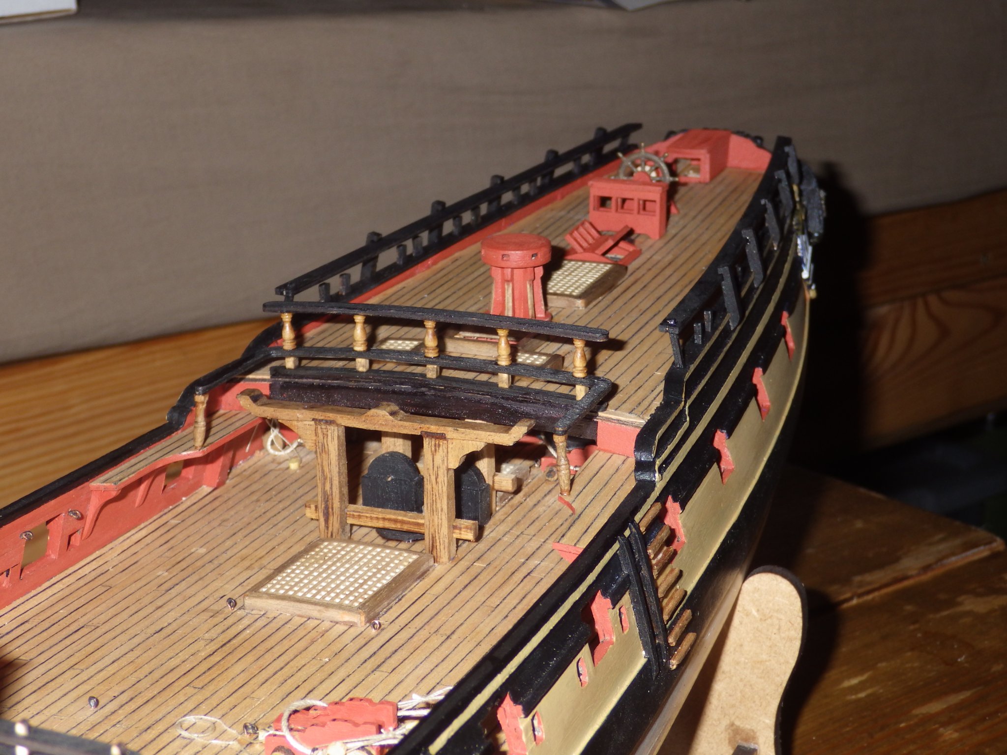
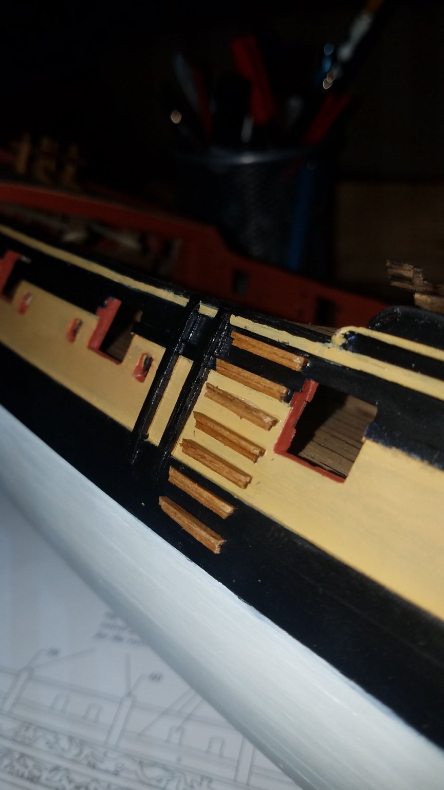
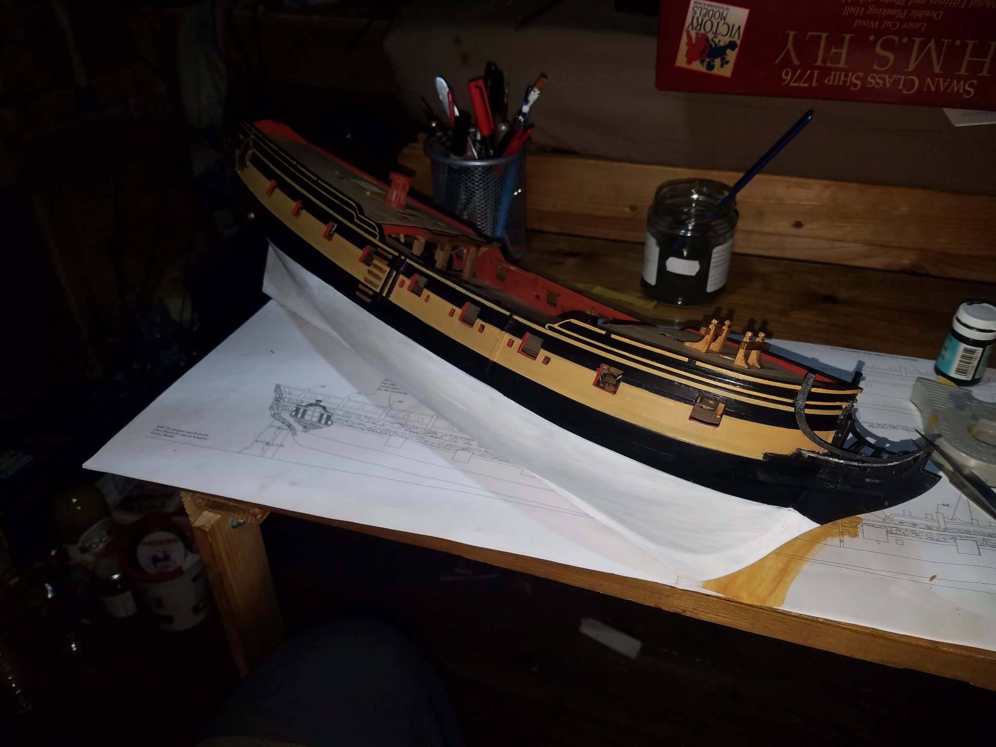
OK, I sorted out my camera and this time got some proper photographs, after some further work and some corrections:
1) I removed the anchor cables, as they were installed over the stopper bits the wrong way. Now I have no rope to work with, so they'll have to wait till I can get some suitable 'rope'.
2) Most of the deck railings are now done.
3) I managed to paint what was visible of the 'covered' gun carriages red, and of course painted red the ones that were not yet installed.
4) I made a 'stove', so now there is at least something black and bulky where one would expect to see a stove!
5) Some more paint touch-ups. It kind of shows that the paint has been touched up several times, but I like that as it is probably exactly how the real thing would have looked after a few months at sea.
6) The bellfry is on, though I should probably weather the bell a little as it looks too bright.
7) I made some very very faint marks for where the countersunk nails (or screws?) would have been on the deck planking.
There is a fair bit of dust on the model, but it should go away with the 'airbrush treatment' and maybe a little brush work. When all is done, I will likely spray a coat of matte acrylic varnish, before I start with any of the masts and rigging, and start to keep the model covered when not working on her.

-
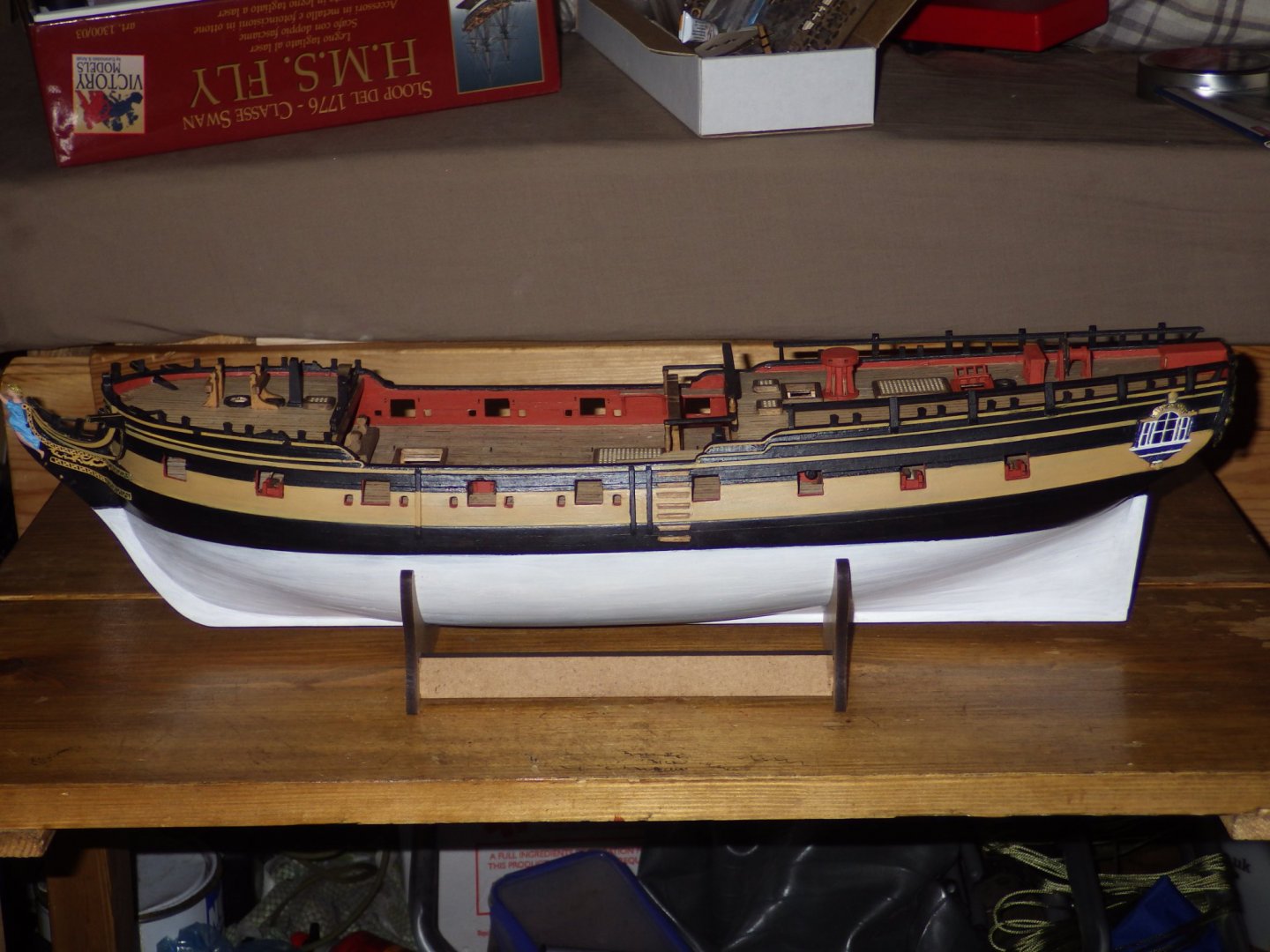
2 hours ago, SpyGlass said:
Really coming along nicely!
Is it the pic - or is this vessel rudderless??
You are correct, I like to work with the vessel on my lap, so I avoided installing too much sticking out of the sides and bottom of the hull for now.
Besides, a competent Master should be able to steer her just by using the foresails and mizzen 😉
-
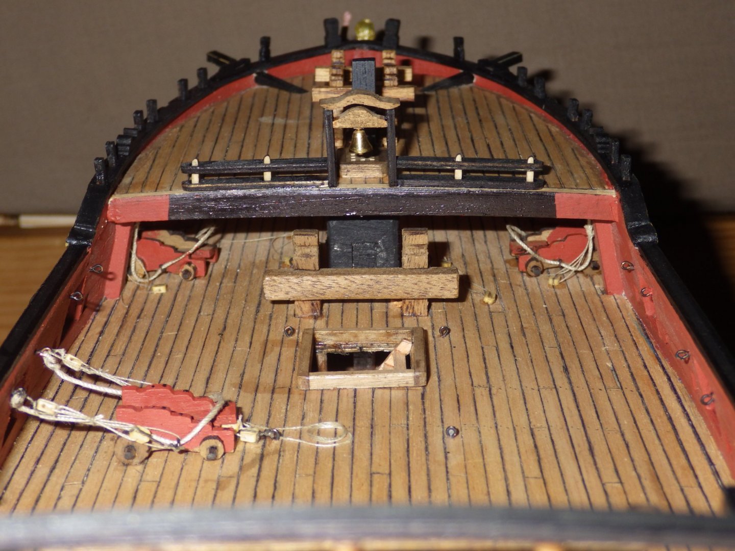
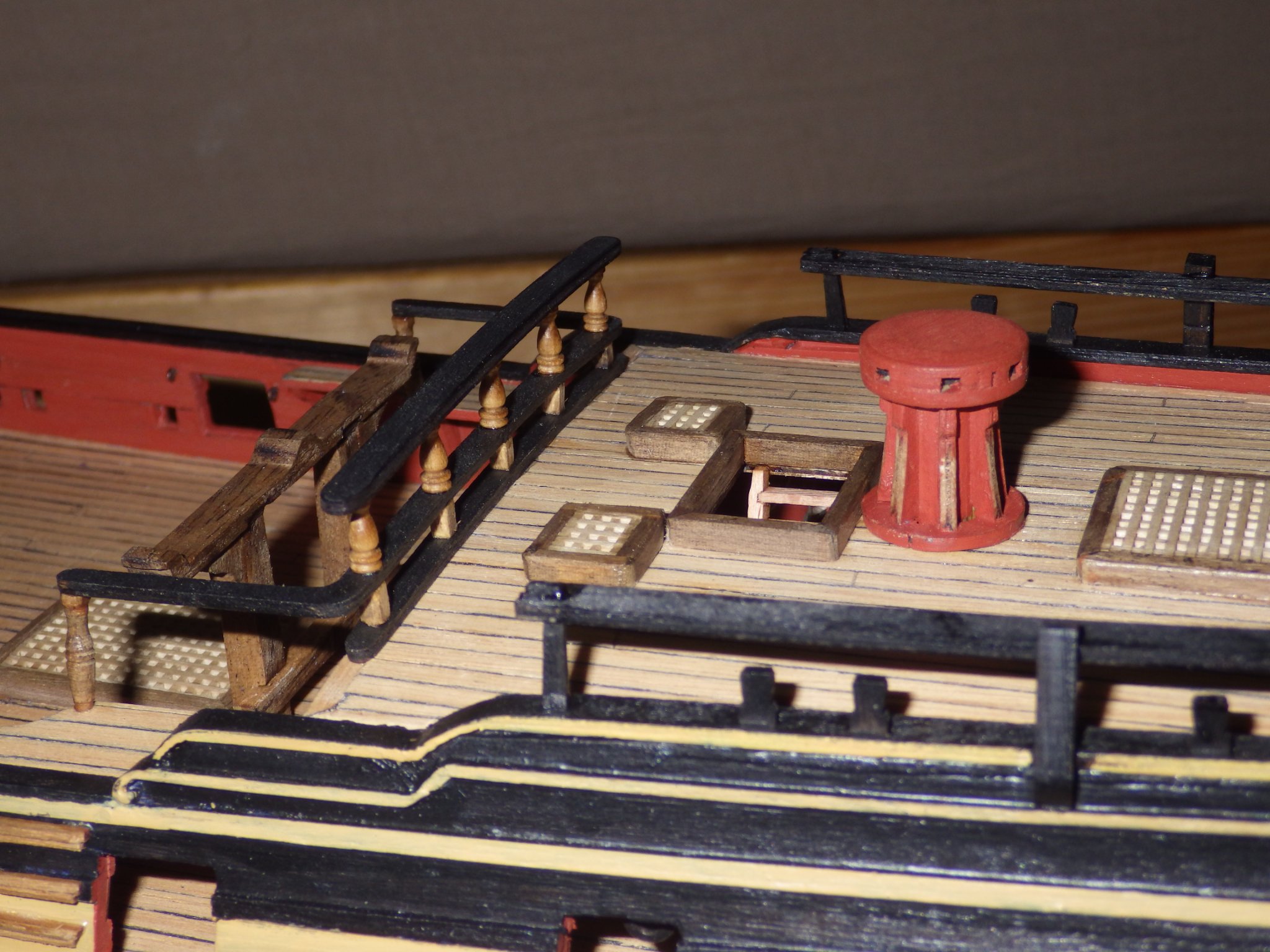
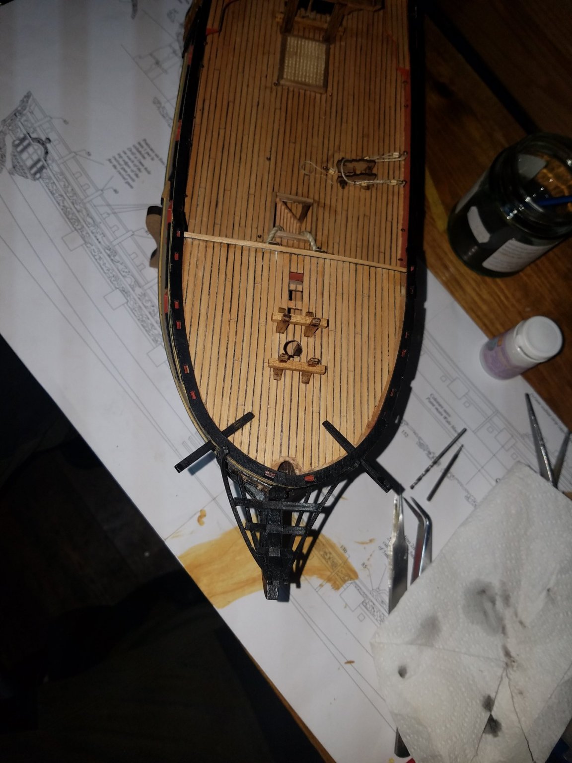
A bit more progress today.
I will need to start thinking about installing the gun carriages and tackle, or it will start getting a bit hard to do that soon!
On that note, I just realised the carriages should have been painted red 😂 I think I can sort that out with a fine paintbrush.
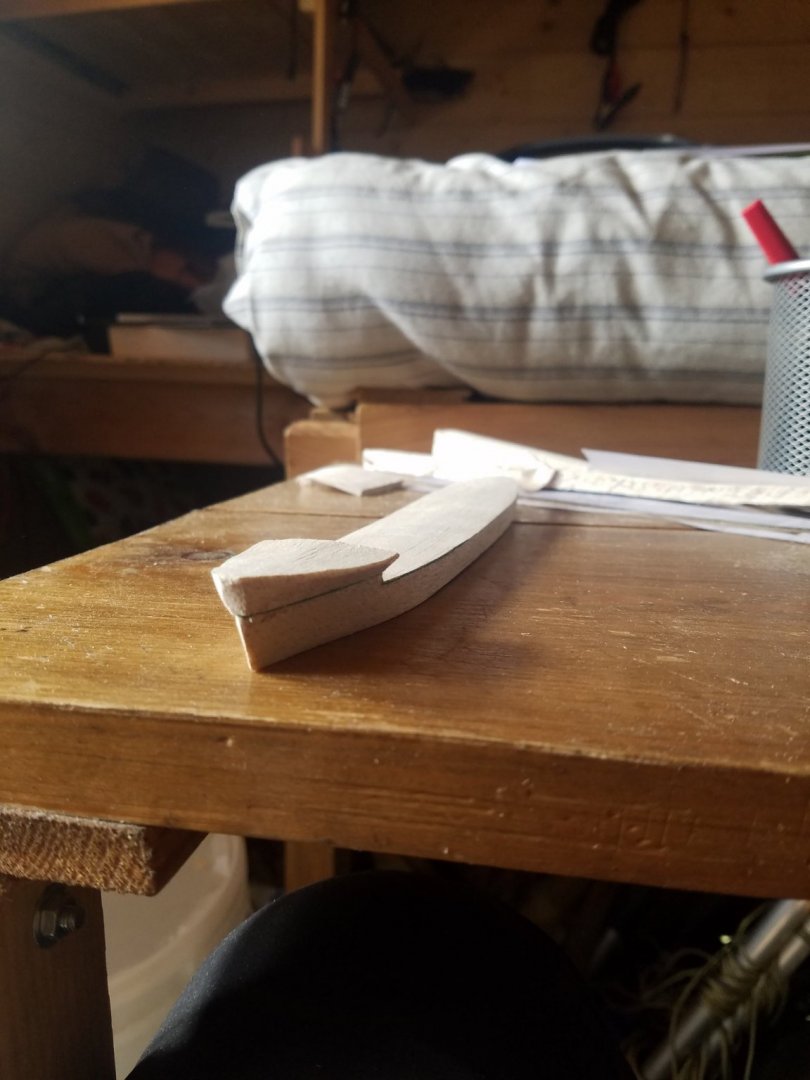
I found the wooden pillars for the railings to be a bit out of scale, so I turned some new ones using a file and dowel on my Dremel.
A few bits of grating, hatch coamings to add, as well as various bits and bobs around the deck. Then, the channels and on to masts and rigging!

-
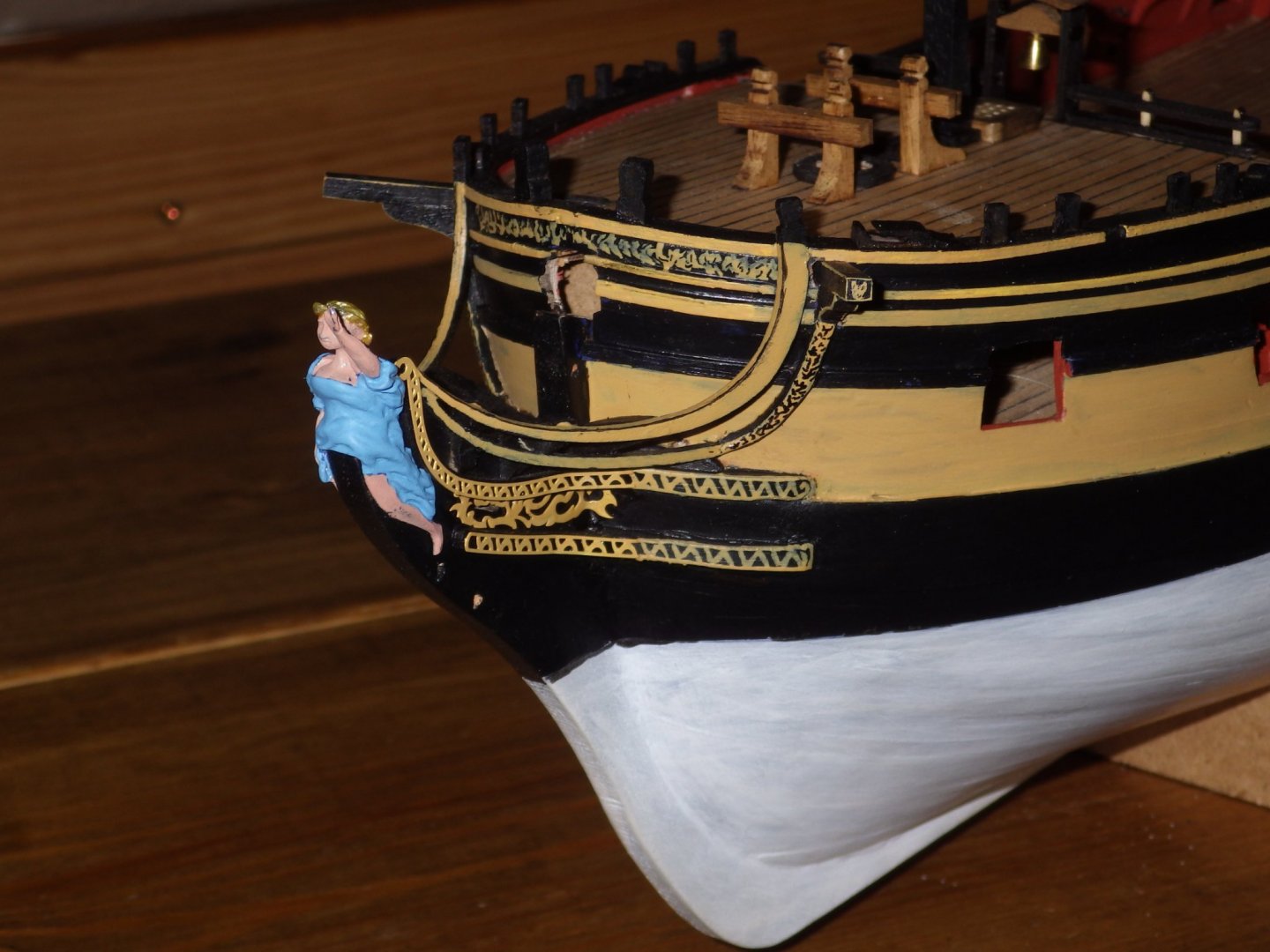
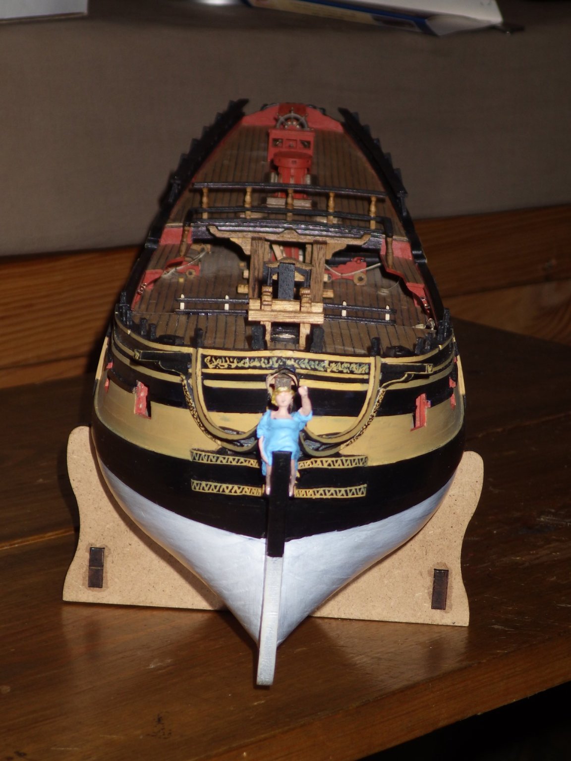
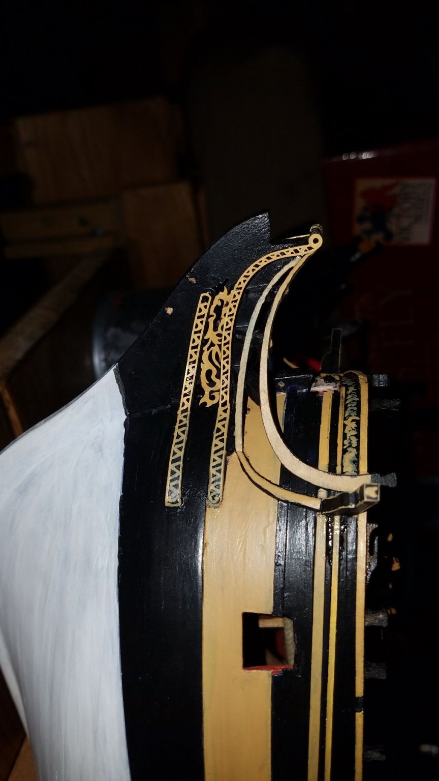
On 1/4/2021 at 4:14 PM, Meriadoc Brandybuck said:
Looking good Sooty! I was a bit sad to see the demise of the decor, but now it looks quite convincing in its Napoleonic era garb.
I had a go at painting the decor around the bow, on the cheeks. Have a look below, half is with PE, the other half is painted. I might strip the PE altogether and paint it all, as I think it looks pretty decent!
Ignore the bit under the top railings, I will sort that out.

-


Armored Cruiser Georgios Averof by GeorgeKapas - FINISHED - 1/700 diorama
in - Build logs for subjects built 1901 - Present Day
Posted
Your work is wonderful! I just started an old Hellenic Navy munition ship (Evros, A415) a few days ago, initially just a waterline model but now adding the bottom of the hull too.
I will be following your build keenly!