


GGibson
-
Posts
1,088 -
Joined
-
Last visited
Content Type
Profiles
Forums
Gallery
Events
Everything posted by GGibson
-
 My $0.02 worth of opinion... Syren. 🤷♂️👍
 -
Never really thought about any coverage on brass, Peter. But, referring to an expert, especially when it comes to brass work in ship modeling, I looked at my copy of Ken Foran's (@xken) book Modeling Building with Brass - 2nd Edition. When discussing cleaning parts, on page 113, he states that "parts that are to remain a natural brass finish can be clear coated, using lacquer or urethane spray can finishes intended for this purpose."
-
Looking good, Peter! 👍🏆
-
USS Constitution by mtbediz - 1:76
GGibson replied to mtbediz's topic in - Build logs for subjects built 1751 - 1800
Hello, Mustafa! Hope you are enjoying your summer break and holiday! I apologize for taking up space on your build log for this query, but thought others might be interested in the picture and in your knowledge of the location. Saw this photo on the Internet of the Sumela Monastery in Turkey and after my first thought of it being an amazing structure with an obviously unique backdrop, my 2nd thought was wondering if you have ever visited?
-
Sharp looking vessel, Scott! Congrats on its completion. 🏆
- 34 replies
-
- 3
-

-
- muscongus bay lobster smack
- Model Shipways
- (and 1 more)
-
Jon, I love that display technique!! Very unique way to expose the details on the gun deck! Yeah, the intent of buying a handful from Model Monkey to start with was to experiment with dissection. So, I'll mess with them sometime. I have plenty of time before I get to that point. I will. of course, being watching your process with great interest. Carry on, sir! 👍🏆
-
Hey, Jon! Your aft planking is looking great! It is interesting to see how you gentlemen are planking the spar deck in order to best expose the details of the gun deck. And I am also very interested in how you are using your Model Monkey carronades. I recall the conversation we were having back in January on Peter's build log regarding these Model Monkey 3-D carronades (starting at Post #427, FYI). At the time, we were discussing the possibility of cutting/separating the cannon and screw adjustment mechanism part from the carriage base, so that the carriage base would be made from wood. I even purchased a half dozen of the 3-D printed carronades to examine ahead of time. But it sounds like you are just going to use the full 3-D printed carronade piece on your ship? Anxious to see how it comes out! Thanks for the update, Jon!
-
Great to hear that acknowledgement from you, Jon. As I said, I'll take the baby-step wins. Thank you, sir!
-
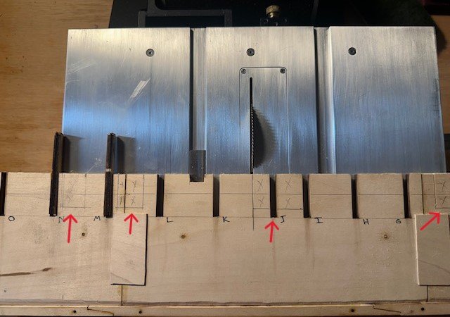
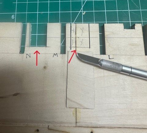
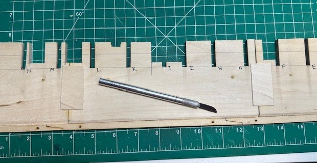
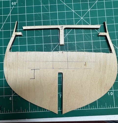
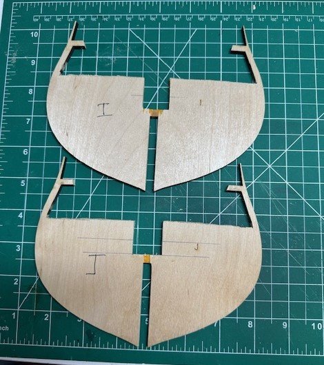
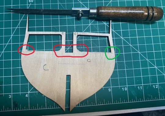
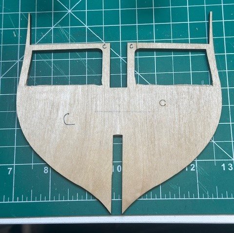
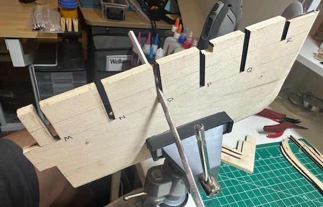
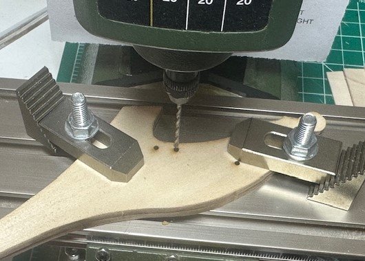
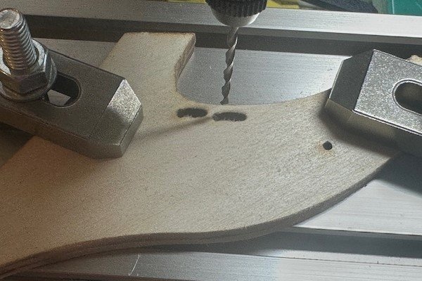
Another (I’ll try to be) quick update on this Constitution build. In my mind, this feels like one of those “…small step for model builder man, giant leap for Gregg-kind” type of accomplishments. I’ll take the baby-step wins when I can get them, because I know a ton of “what the…?!?”s will cross my lips ultimately in this journey, as well. First thing I wanted to get done was what I had mentioned at the end of my last post… and that is to insert some brass tubes up through the keel and into the bulkhead former a bit in order to provide additional support for when this ship is placed in a permanent base. Several builders have done this on whatever ship they were constructing, and I mentioned that Jon gave an excellent tutorial on what he did early on for his Constitution, so… I had to follow suit. I decided to place the two support holes about 12” apart, approximately at the F & N bulkhead locations. Using just a pin vise and drilling holes by hand, I had to accurately drill straight down through the rabbet and keel in order to insert a 3/32” tube at each spot. I started with a #60 micro drill bit and carefully worked my way up through larger drill bits so as to not tear out the hole. So, a #60 drill bit, then a #54, then a #50, then 5/64”, then finally a 3/32” bit so that I could tap in the small tubes. Sweet! I had also mentioned in my last post that I was considering making some cuts into the appropriate bulkheads and keel locations in order to have visible ladders going from the detailed gun deck down to what would be the berth deck. I looked at what others had done to the bulkheads and bulkhead formers to accomplish this visual. Some had made the cuts at this stage, others had made cuts into the frames after the bulkheads had been secured to the center spine. I decided to do this before attaching the bulkheads. After reviewing several previous build logs and several USN documents, I made the following cuts in the center keel… For the fore hatch going down to the berth deck, I cut out the center keel 19.34mm back from the Bulkhead F and 1” deep. For the main hatch going down to the berth deck, I cut out the center keel 37.12mm back from Bulkhead I, which removed all from between Bulkheads I & J and went back another 12.44mm from Bulkhead J. For the after hatch (the one that will be just in front of the capstan), I cut out the center keel 19.43mm from between Bulkheads L & M, beginning 9.78mm back from Bulkhead L. For the companionway hatch (the one that will be just behind the capstan), I cut out the center keel 19.43mm from between Bulkheads M & N, beginning 14.52mm back from Bulkhead M. In addition to the cuts made to the center keel, cuts also need to be made to a couple of the bulkheads that will be in the way in order to accommodate the “ladders to the berth deck” illusion. So, the gun deck beams from Bulkheads I & J were removed now (other gun deck beams will be removed similarly later) as well as some deep cuts. According to the USN plans (and looking again at other builds), it appears all of the gun deck hatches going down to the berth deck are 5’ wide, which translates in our 1:76.8 scale to 0.78125”. So, the openings in these bulkheads were made that wide. And, yes, the beams that are being removed will be saved in order to use as templates for when the new beams are added back in later on in this build process. And, yes, I am still worried about snagging and breaking off at least one of these bulkhead extensions at some point during this build process! Uggghhh... So, all in all, a good start to the first major bashing in this project. I believe, then, that the next task is to get the Lego blocks out and, after a bit of initial fairing on a few of the bulkheads, secure each of the bulkheads to the center keel. Then, begin on the filler blocks. Thanks, as always, for peeking in. Appreciate the likes, comments, advice and criticisms.
-
These coins look really cool, Gene! Nice work! Do you have a list of the 12 images you have created to-date? I didn't see that on the Amazon page. Would be an interesting addition to my Constitution build and display when I eventually finish it... 🤷♂️😬🤣 Again, beautiful work, Gene! I wish you great success!
-
Thanks for the input, fellas! Yeah, it seems like that is the proper thing to do. I may look at "pre-sanding" some of the "end bulkheads", i.e. Bulkheads A, B, Q, R, that will require a deeper sanding than others to eventually fair properly but otherwise will hold off on the detailed fairing until all bulkheads are in and I can test them with a planking strip. Appreciate the reminder, gentlemen! Last night I did give each of the bulkhead tops a nice, thin coat of Titebond glue to help strengthen them, as I know I am bound to snag one or two of them during this build/install process. Hopefully. a nice topcoat of this glue will toughen them up to prevent any serious *SNAPS*... 🤷♂️😬 Before I begin securing the bulkheads to the keel, I am thinking this would be the best time, if I am going to do it, to drill holes in the bottom of the keel in order to insert brass rod and tubes to help hold and provide additional support for the ship on whatever type of pedestal/cradle base that is eventually made for its display. Although other builders may have done this, I do know that Jon Gerson described his process of doing this very well in his build log. Thanks, Jon! 🏆
-
Yeah, that's pretty much what I meant, Peter. Thanks for the correction! 👍
-
USS Constitution by mtbediz - 1:76
GGibson replied to mtbediz's topic in - Build logs for subjects built 1751 - 1800
Looks like an enjoyable summer with family, Mustafa! Enjoy, my friend! 🏆👍 -
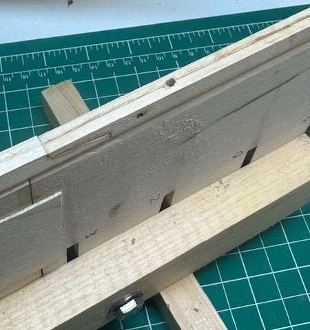
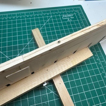
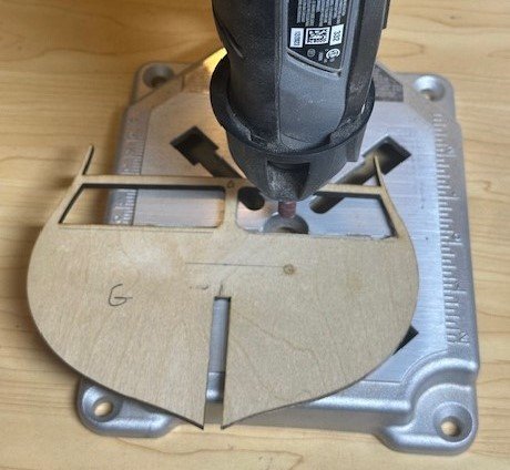
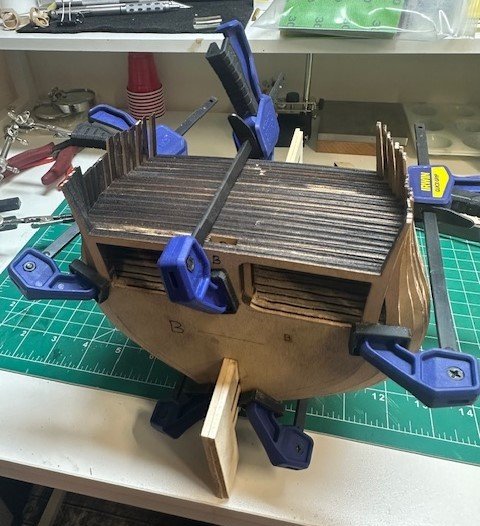
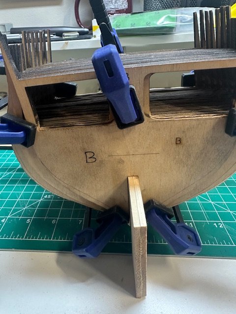
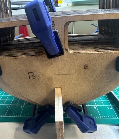
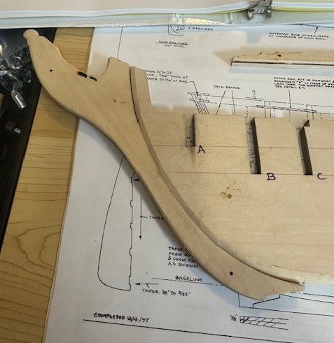
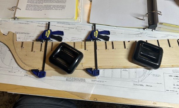
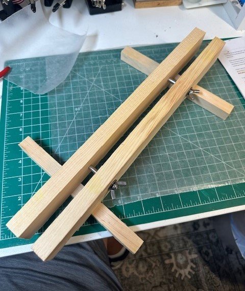
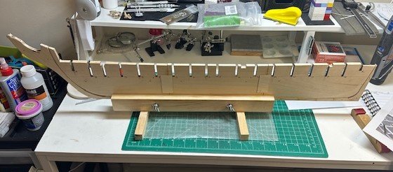
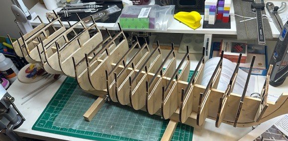
Well, another (fairly brief) update as I’ve done a bit more work and taken a handful of notes. We spoiled the grandkids during their extended visit for this summer and, of course, the grandkids wore us out. The house is back to being quiet, so I’ll try to get back down to the shipyard more frequently again. I left off my build log having scribed and drawn the 3/32” lines to reduce each of the bulkheads, in order to compensate and allow for the detailed gun deck. So, time now to get the Dremel on the drill press workstation and sand down all of the bulkheads. The process worked out pretty well, although I had to use one hand to pull the workstation handle down to lower the Dremel and the sanding drum and the other hand to guide the bulkhead across its sanding path. The sanding really took it out on the sanding drums, too, chewing them up pretty bad, and I had to replace the drums after each bulkhead. Also, even though I was using the smallest diameter mandrel and sanding drums I had, I was not able to get tight into the corners of each bulkhead, so I used my Zona saber blade to trim the corners. That worked out well. I also used my Dremel and sanding drum to taper the bulkhead former at the bearding line. I scribed lines on the bottom of the bulkhead former where I needed to narrow the thickness for the rabbet and sanded down to those lines from stem to stern. I also sanded and cleaned up, as best I could, the laser char from each bulkhead slot and bulkhead former slot piece (clamping them in a vise). Then, using a technique I saw Tom (usedtosail) use in his build, I placed all of the bulkheads in a scrap piece of ¼” thick basswood and lined up all of the gun deck level beams so that I could then see how my “adjusted” spar deck levels were across all of the bulkheads. I took a long file to smooth them all down as best I could to an even level. There are subtle visible changes in the before and after pictures. Also, as just about everyone else has done and as recommended in the practicum, I placed a piece of 1/32” x 1” x 2” basswood on both sides of the bulkhead former joints in order to provide additional reinforcement support. One of the definitive differences between the 1812 Constitution version and other periods was the use of rope for the gammoning on the bowsprit and stem rather than chain. So, since my goal is to be “1812-ish”, and whether this is actually correct or not, I placed the stem piece on my mill and widened the two simple holes at the top of the stem piece to eventually accommodate the rope that will hold the bowsprit to the front stem. Also, before securing the stem piece onto the bulkhead former, I used a round file to shave a small groove at the top of the stem for the eventual placement of the bowsprit. Seems like a good time to do this while the stem piece is free. Although I have probably forgotten some important task, I think I am ready to secure the stem, sternpost and 3-piece center keel assembly to the bulkhead former. Using some Titebond CA glue, a couple palm-sized 3.3 lb. dive weights and some clamps, I attached the keel framework. Since I first started this hobby, I have been using my Amati “Keel Klamper” vise to hold my boats while under construction for as long as possible, and it has worked out well. However, the vise makes the ships sit fairly high off of the table and, with the Constitution being a big (and long) ship to begin with, I thought it would be good to have a different keel clamp. I had seen on some other build logs, like Mustafa’s, for instance, that a small clamp had been constructed, so… I did the same. A couple of 15” x 1½” x ¾“ strips along with two (2) legs at 8” x ¾“ square and some ¼“ bolts and nuts. At some point, I may move this ship to a cushioned cradle, but for now, let’s try this keel clamp. So, I have “test-placed” the bulkheads in their appropriate BHF slots. As was suggested in the practicum, I have placed Bulkheads A-K with their printed letters facing the stem forward, and Bulkheads L-R facing the stern. I need to do more work on Bulkheads K, M, N & P to get them to fit in their slots. And, although I have penciled the bevel marks on each of the necessary bulkheads, I have not done any beveling and am weighing the alternatives about doing some of the beveling now before they are secured vs. waiting until they are in place. I am also considering making some cuts into the appropriate bulkheads and keel locations in order to properly display the ladders that will be going from the detailed gun deck down to what would be the berth deck. That is my next project to be completed. As always, appreciate the likes, comments, criticisms and advice. Thanks…
-
...but, after all that work, put them on your spar deck, instead!! 🤷♂️🤣 Nice work, Peter!
-
Welcome, Gene! Will be interesting to see info on the engravable brass coins!
-
Thank you, Eric! Just getting started on the Constitution... and it's going to be a long build... so get a comfortable chair! 🤷♂️🤣
- 58 replies
-
- 2
-
-
- Santa Maria
- Ships of Pavel Nikitin
- (and 1 more)
-
This is interesting, Mustafa. And, I assume, using a hand-held pin vise? I don't think my Proxxon has a reverse gear! 🤷♂️😅
-
Sounds like boxwood is the way to go for these smaller parts. I really haven't had the "need" to have any boxwood for previous builds, but from all of your build logs I am reading, I purchased a small supply of boxwood for my Constitution from Joe at Modeler's Sawmill. got a few 1/32" & 1/16" thick sheets, as well as some strips for deck planking. Not sure if I saw this explained previously, Peter, so sorry for asking again if I missed it. When you cut and drilled these gunport lids, did you initially drill the holes from long strips and then cut the lids to size, or did you cut to size, then drill the necessary holes? Do you cut the holes with some waste wood behind the pieces being cut? Always interested in others' processes... Happy 4th! USA, USA!!
-
Good to hear that's not going to be an issue for you! Appreciate the offer, Peter, but my local Woodcraft store had some in stock. Picked up a 1" x 9" x 3' piece. It really does look nice and should make an awesome base. Haven't decided yet on type of mounting hardware/configuration but really thinking about Jon's solution using brass tubes and rods for additional support, whatever is used. Take the wins when you can get them! 👍🏆
-
Martindale blades for Byrnes saw...
GGibson replied to CPDDET's topic in Modeling tools and Workshop Equipment
I got a smorgasbord... 0.020", 0.030", 0.040" & 0.050" thicknesses in various quantities - All cutting saws, 3" diameter, 1/2" hole, 90 teeth -
Martindale blades for Byrnes saw...
GGibson replied to CPDDET's topic in Modeling tools and Workshop Equipment
I was not aware of this! Thanks for the heads-up! I placed my first order with Malco around the first of the year for my (at-the-time) newly acquired Byrnes saw. Excellent saw blades, although I was pretty much past any serious cutting stages on my previous build (and, frankly, I, too, was disappointed in the shipping delays, totally UPS fault, though, not Malco's). Looking forward to using the Byrnes and blades more as I begin my Constitution. Again, thanks for the info! 👍 -
Agreed! Do whatever you feel you need to as the builder, Peter, but don't think anyone is going to comment on any cannon size disparity. Can't remember if I have seen pictures of your base and pedestals previously, but I am really liking the looks! Great job! I just purchased a piece of canarywood that I am going to use (eventually!) for my Constitution base.
-
Nice comparison exercise, Peter! I hope you like Ropes of Scale. They do have a light beige, as well.

