BETAQDAVE
-
Posts
5,386 -
Joined
-
Last visited
Content Type
Profiles
Forums
Gallery
Events
Everything posted by BETAQDAVE
-

Homemade Spray Booth
BETAQDAVE replied to BETAQDAVE's topic in Modeling tools and Workshop Equipment
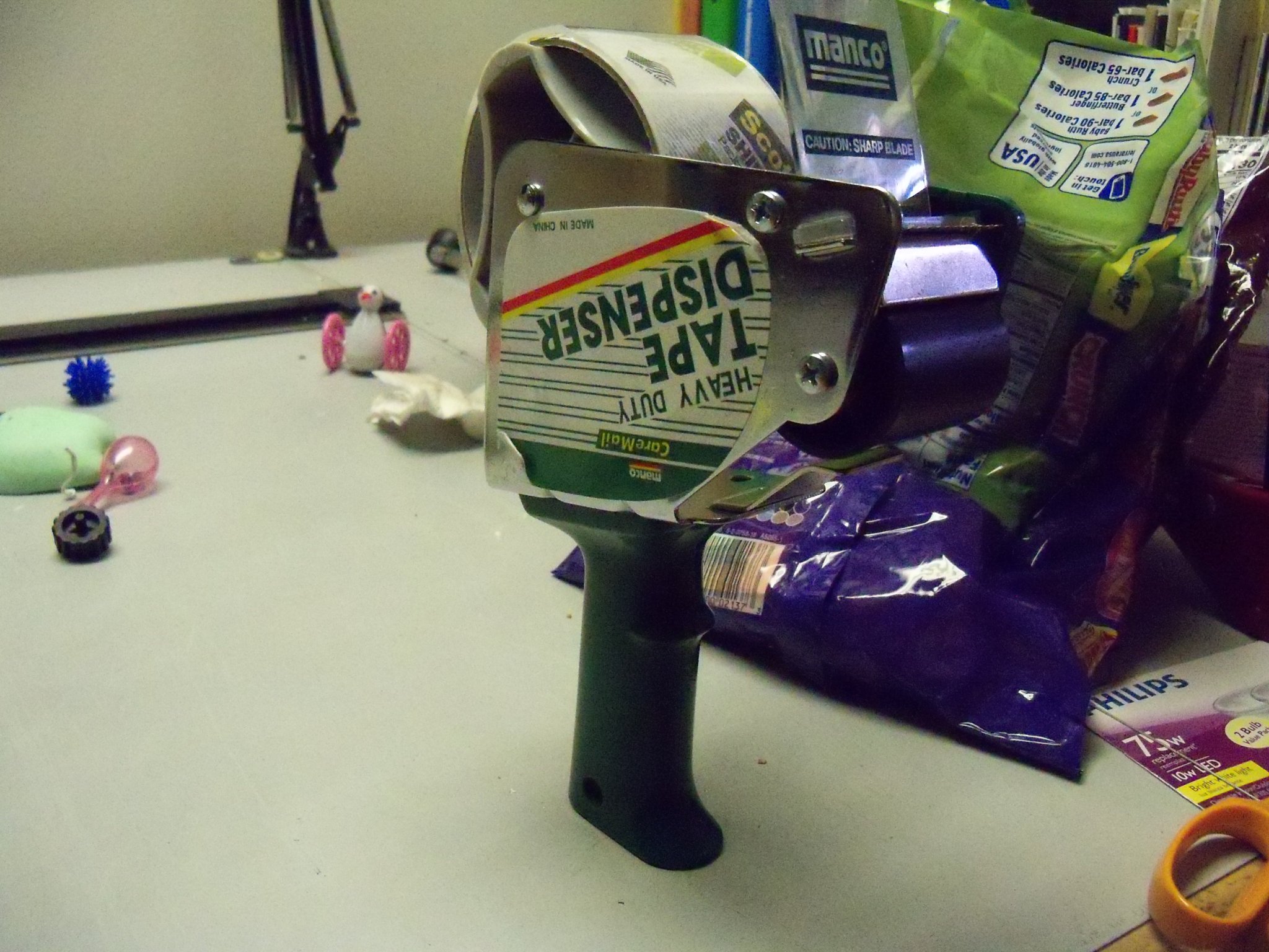
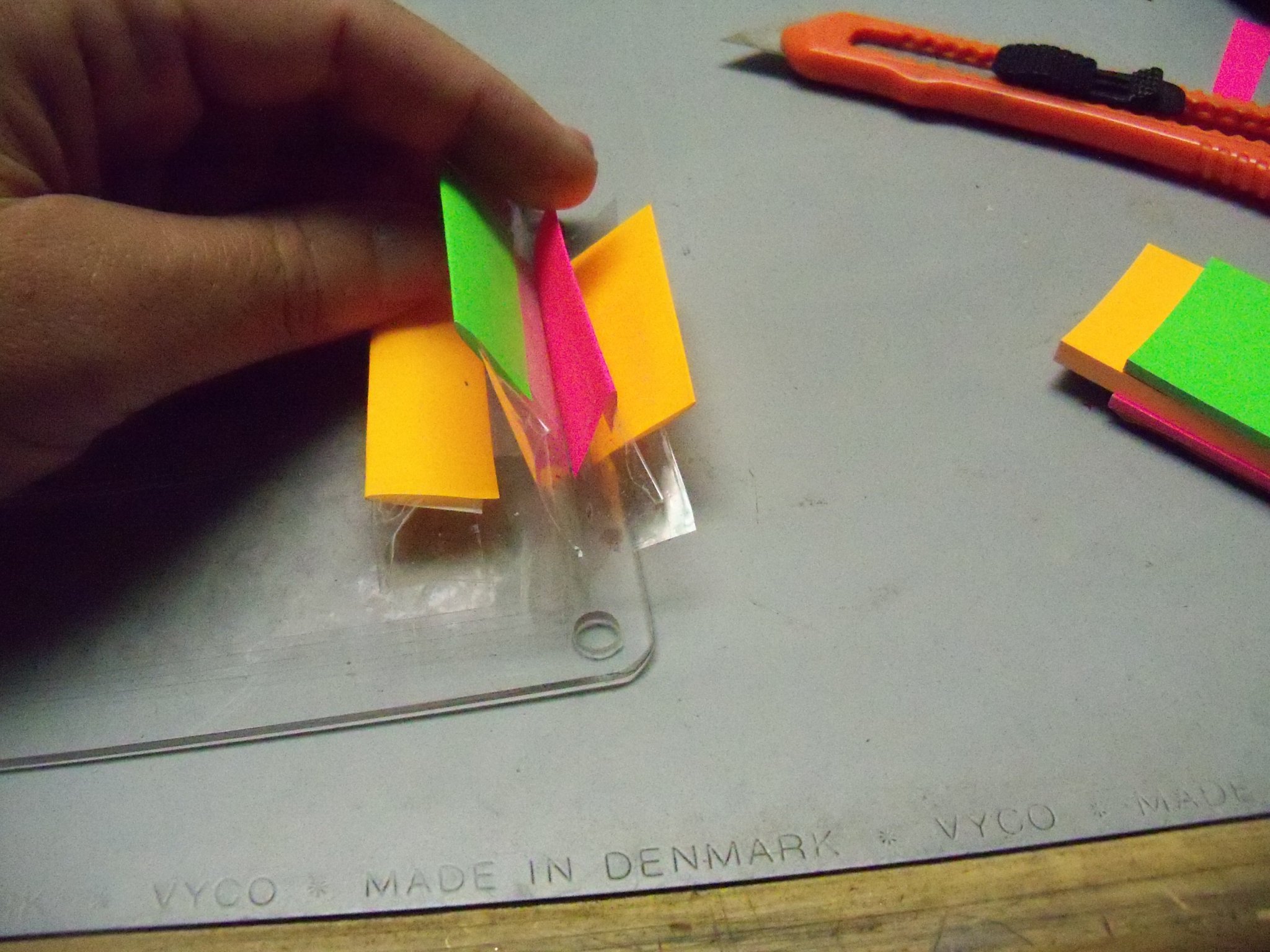
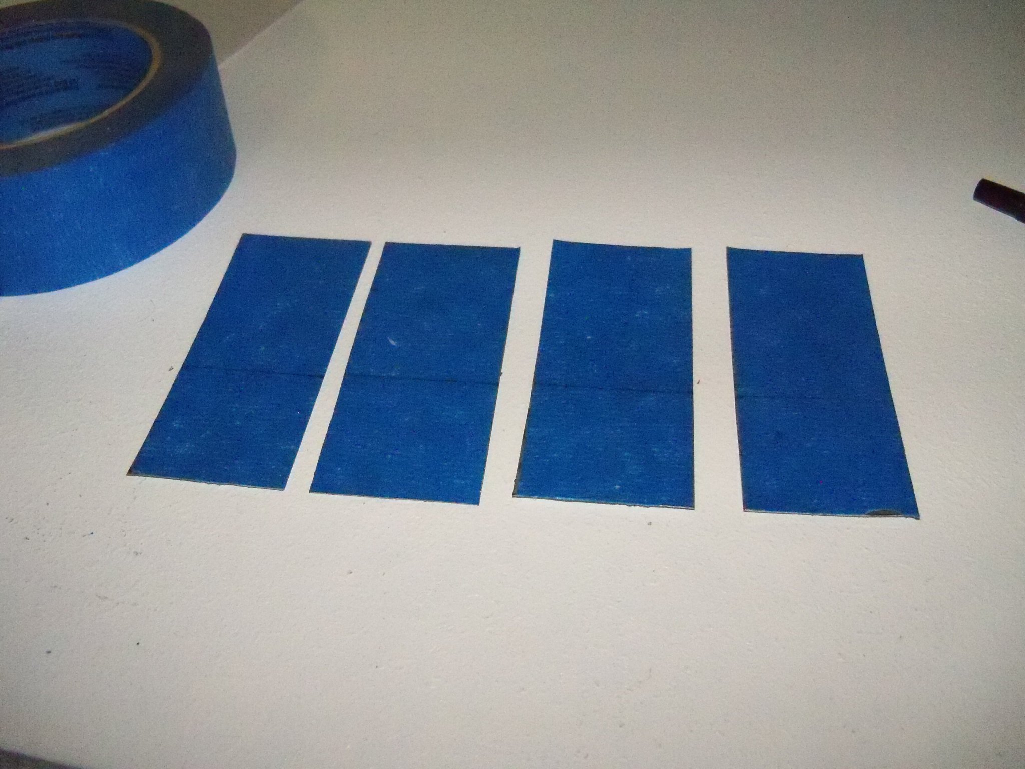
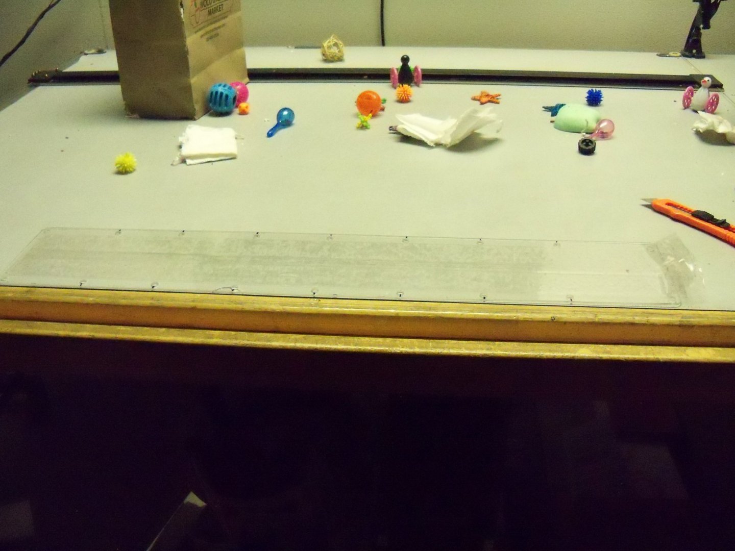
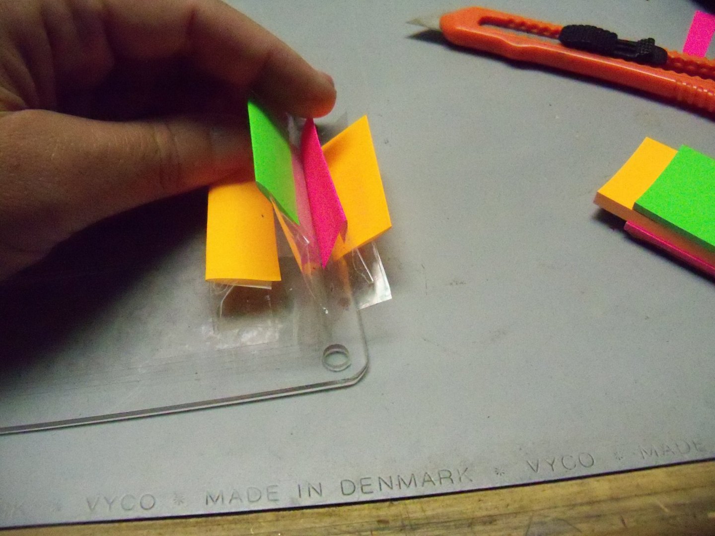
I have a pair of draw catches to install that will pull the top panel down to compress the foam weather-strip and seal the plenum. Unfortunately installing anything with screws into the edge of particle board simply splits it when pressure is applied (I tried that already), so I’ll need to come up with another method of attaching the catches. Today I took the Plexiglas window upstairs to my desk/bird playground to install the tear-off tapes. I cleared off a space to lay the window down flat and since you need both hands to apply the tape I used a piece of double sided tape under each end to keep it from shifting around. Because my window is wider than the tape, I had to use two pieces of tape overlapping each other roughly one inch down the center. While trying to do this operation, I have one suggestion on how not to do this. If your tape is on one of these useless dispensers, get rid of it and just use the tape directly from the roll. It may work on taping packages, but it just got in the way here. I stretched out the first piece of tape aligning it by eye just inside the holes on the edge. Securing the left end of the tape an inch or so beyond the end of the window, I stretched the tape while still on the roll about an inch or so beyond the other end being careful not to touch it down on the window yet. With my left hand I smoothed the tape down onto the window from left to right trying to eliminate any air bubbles as I went. (Not as easy as you think!) Once I had the whole length pressed down beyond the right end, the tape was folded back on itself forming about a one inch tab at the end. I repeated the steps above with the overlapping piece of tape, but the end of this tab was wrapped around the previous tab at the end. This will allow me to pull just one tab to remove both pieces at the same time. I placed three more layers similarly over the first one and trimmed the ends of the tape off on the left with a box cutter. To make it easier to separate the different pull tabs I decided to cut some different colored pieces of post it notes and tape it to the various tabs. Oh, and one more suggestion. Once you have removed the window from the booth, make sure that you are putting the tape on the correct face of the Plexiglas or your screw holes will not line up properly when you reattach it to the booth. (Don't ask how I know this!)
-
Homemade Spray Booth
BETAQDAVE replied to BETAQDAVE's topic in Modeling tools and Workshop Equipment
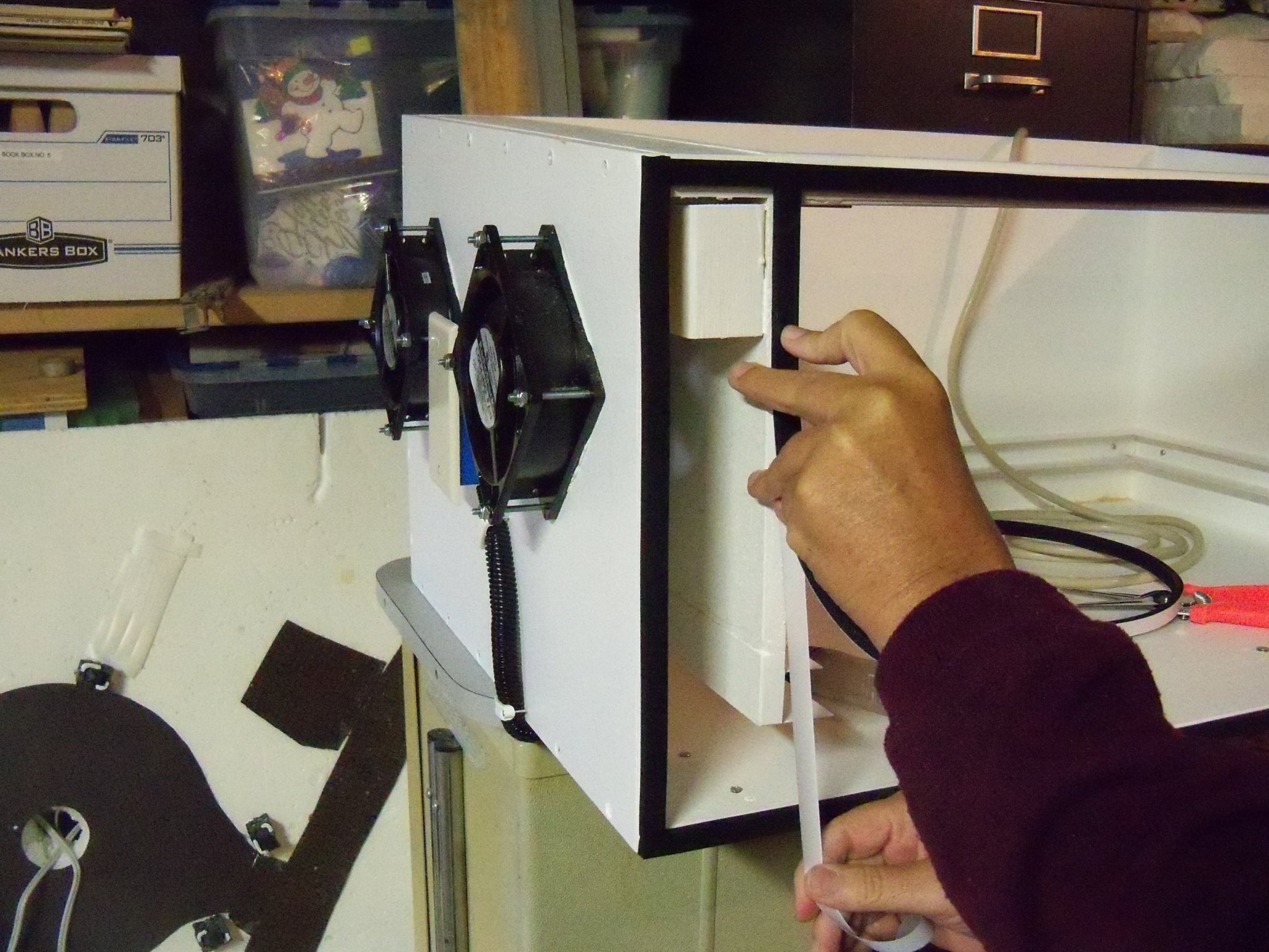
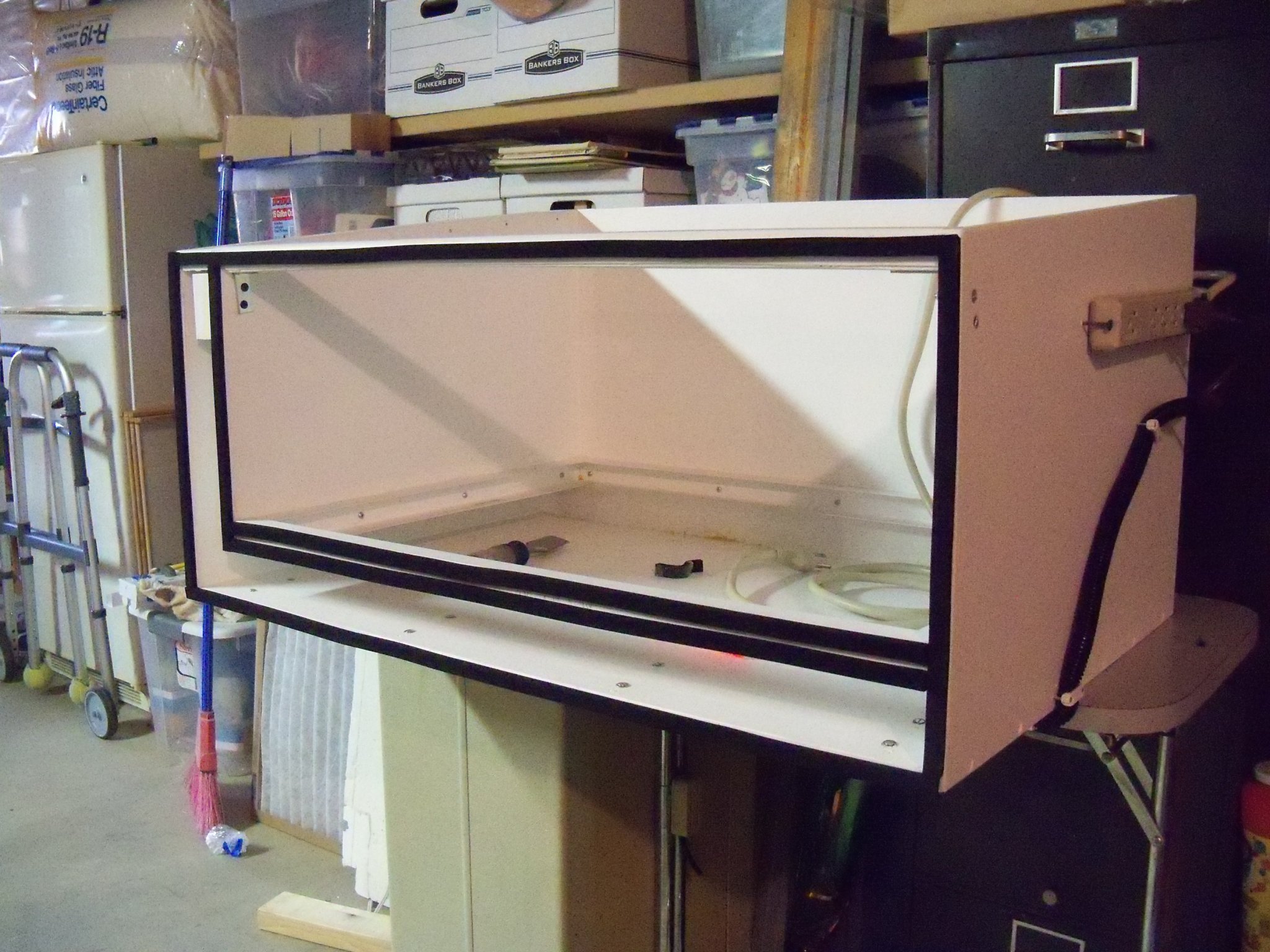
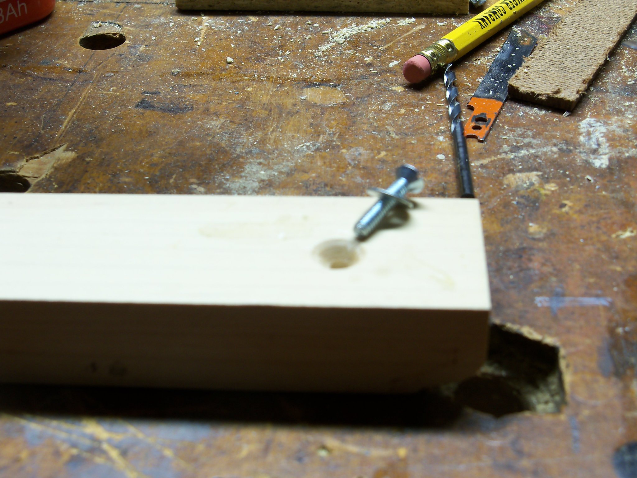
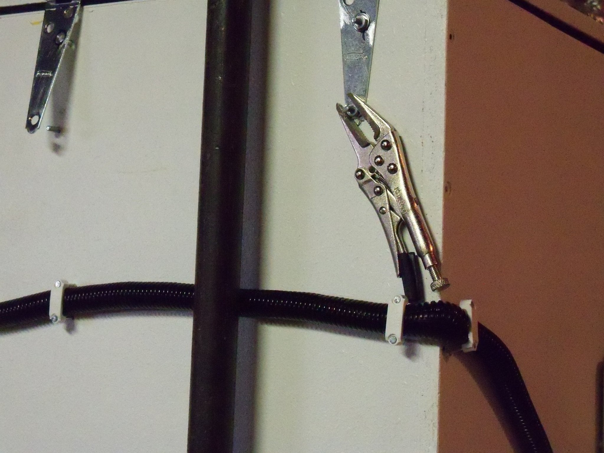
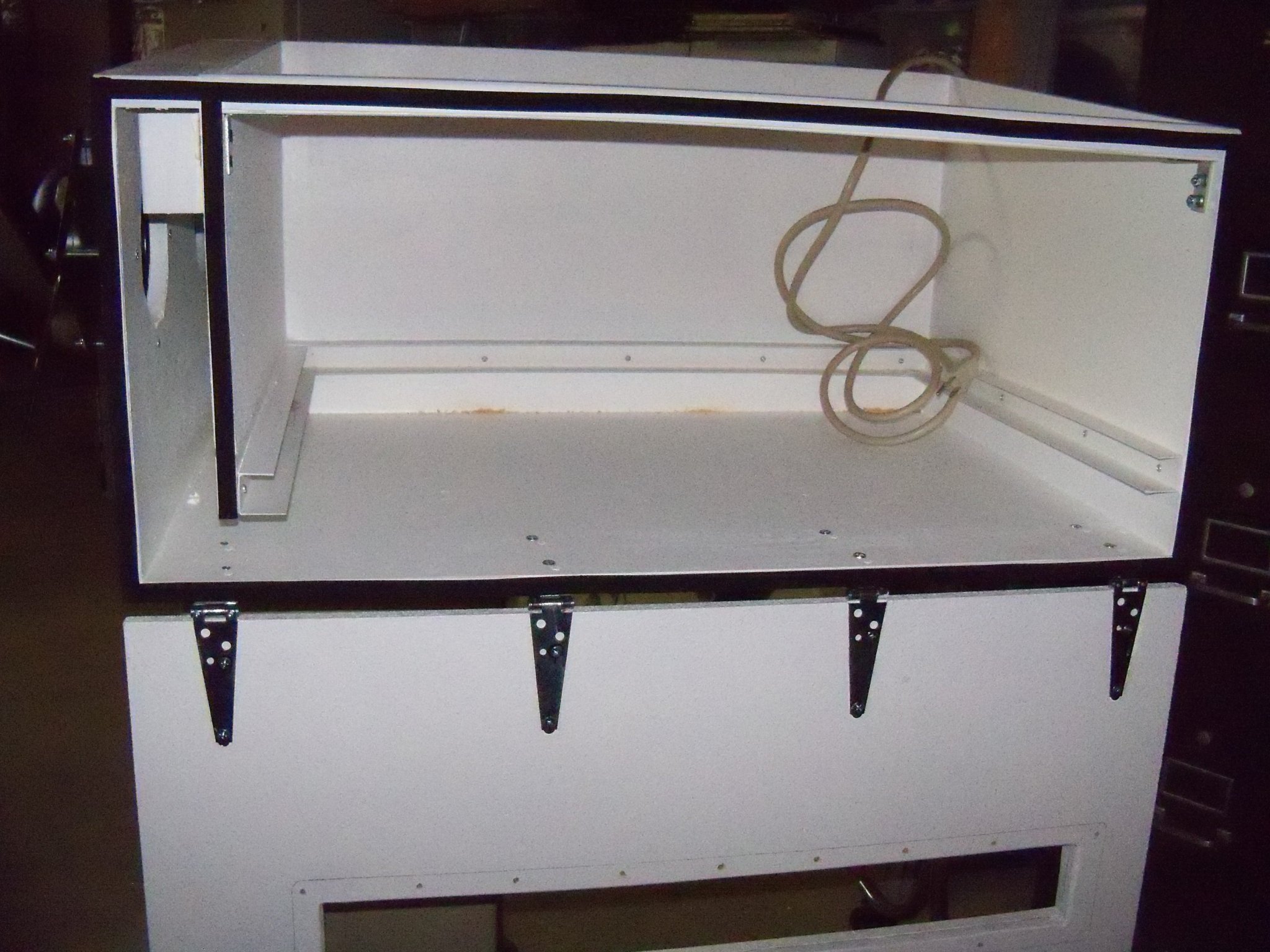
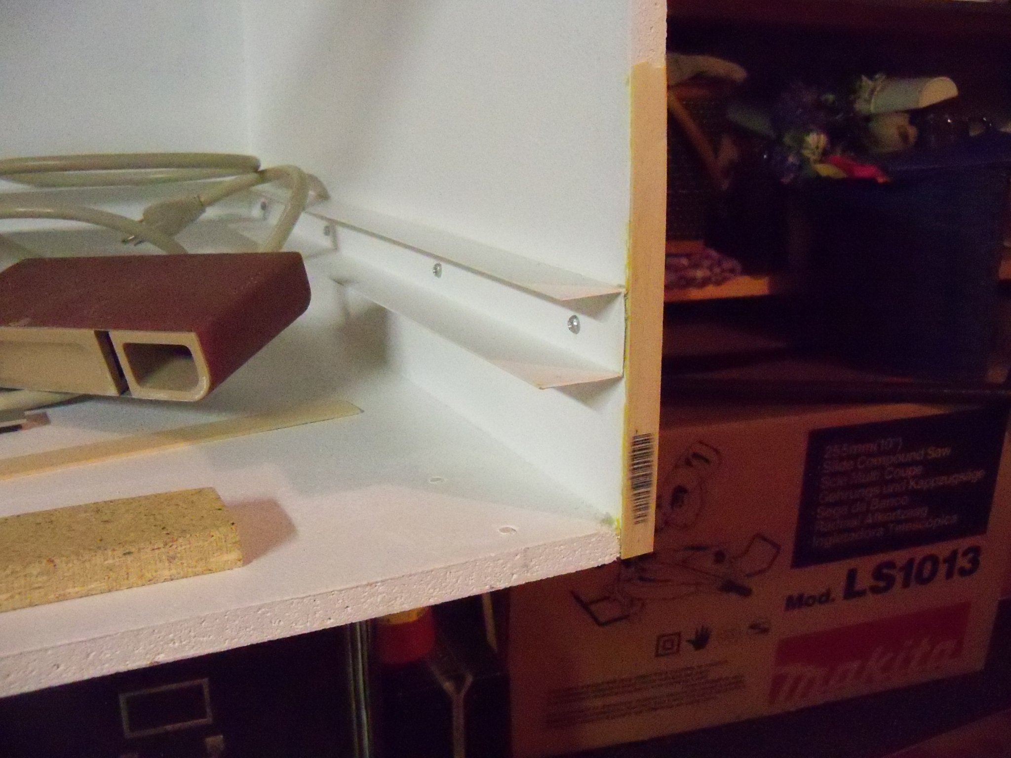
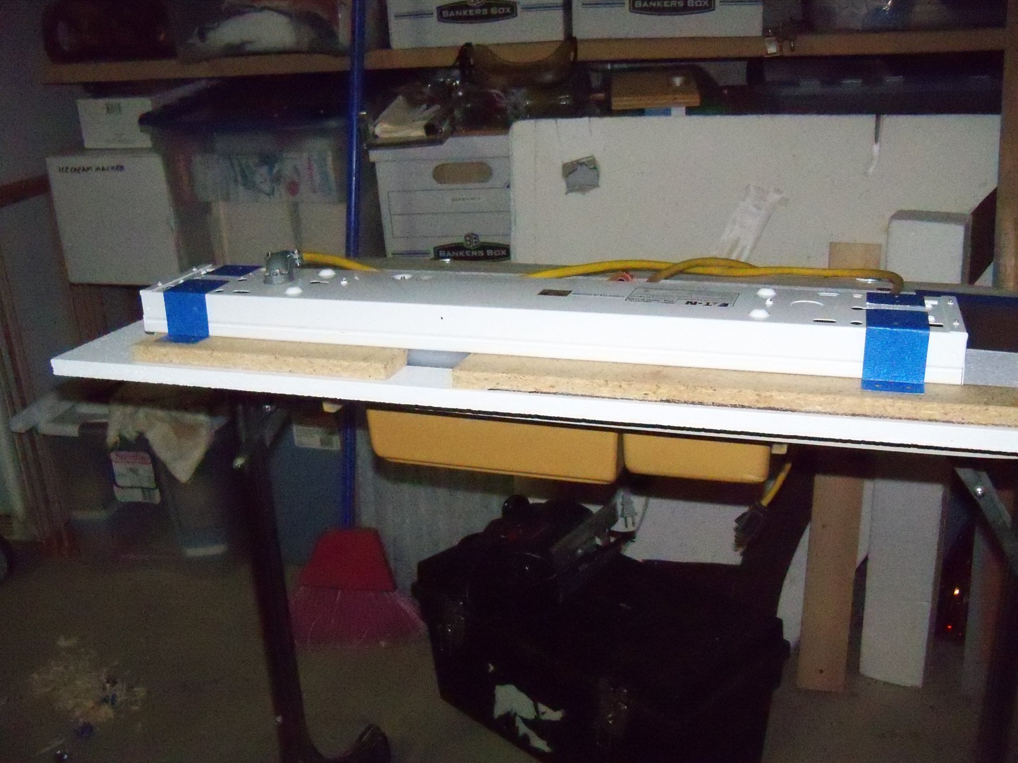
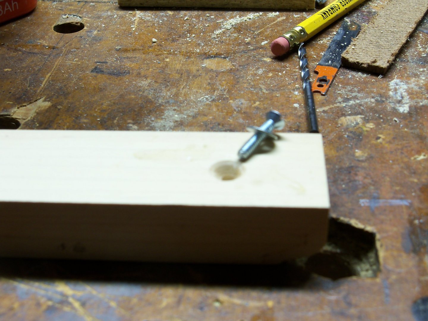
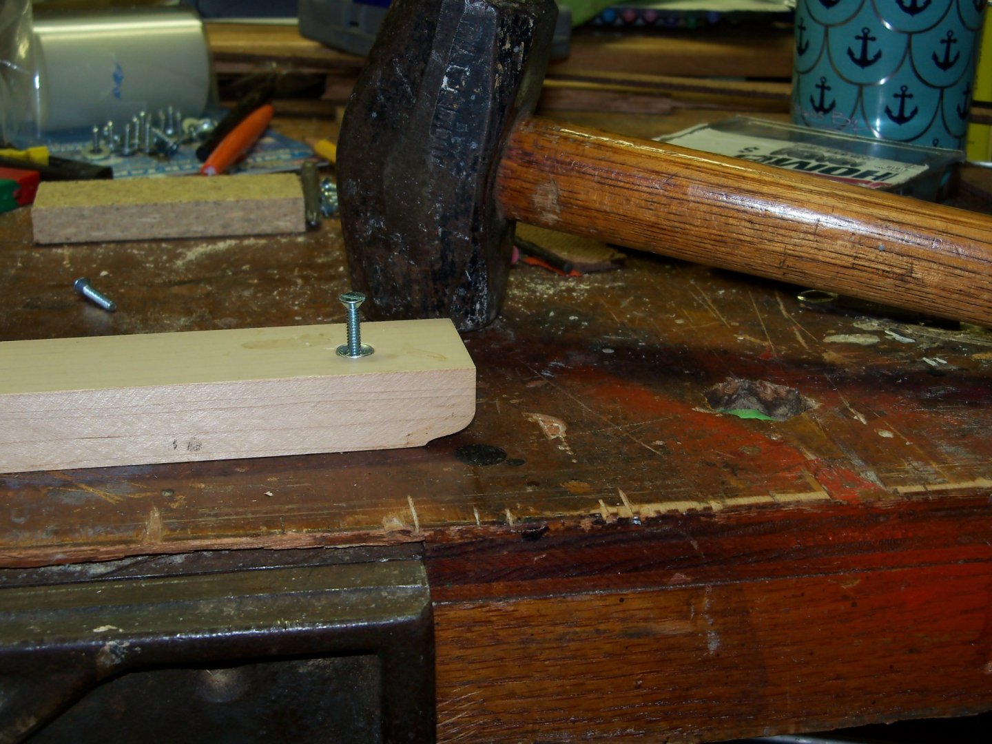
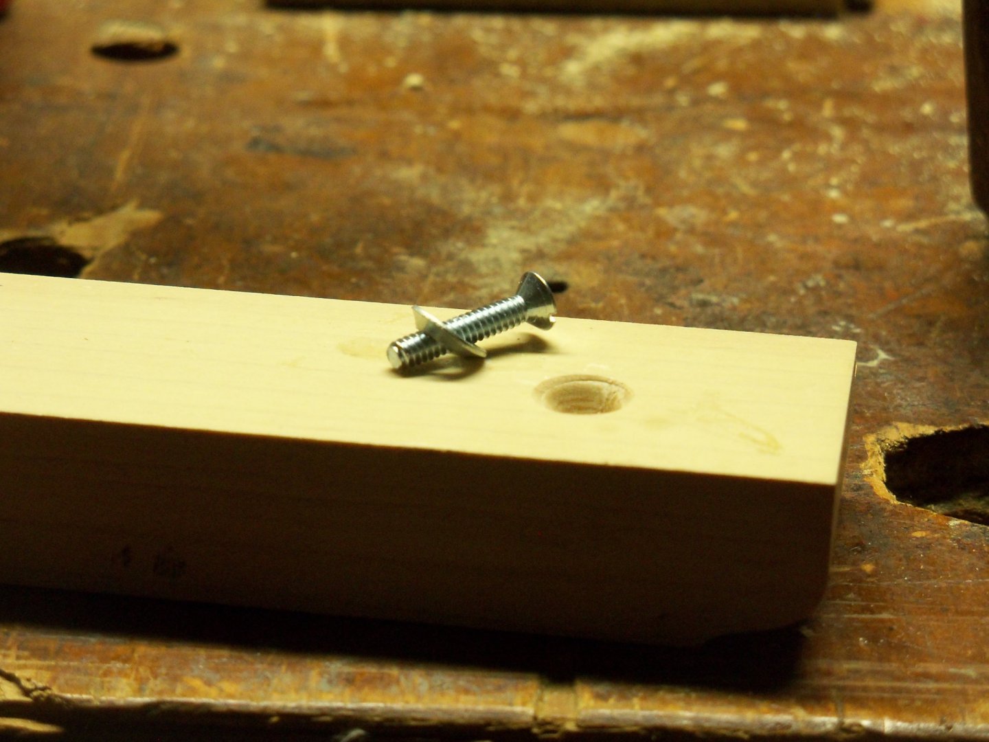
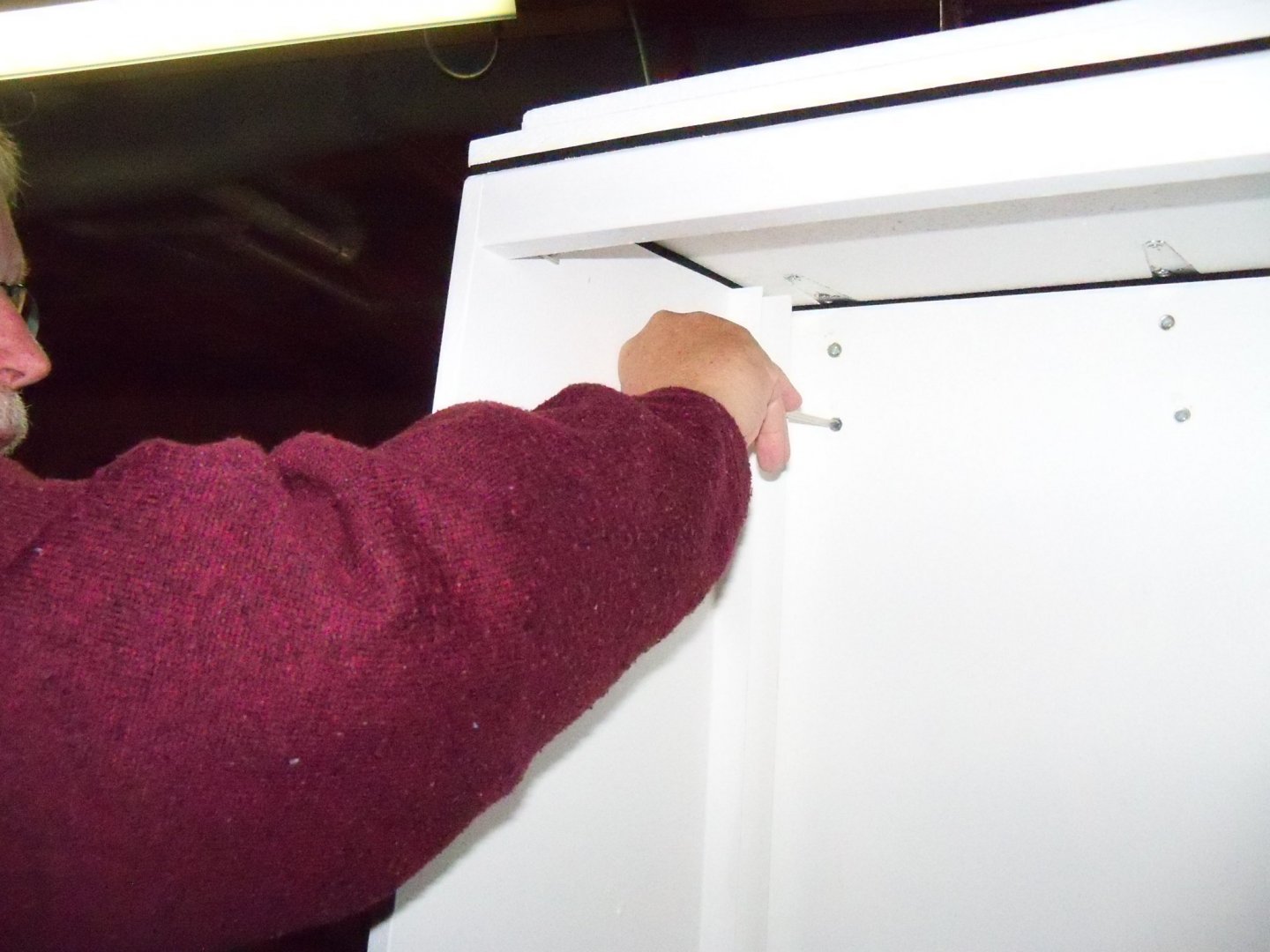
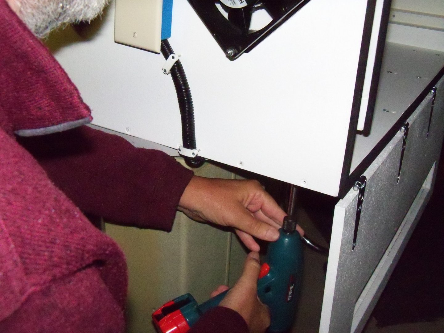
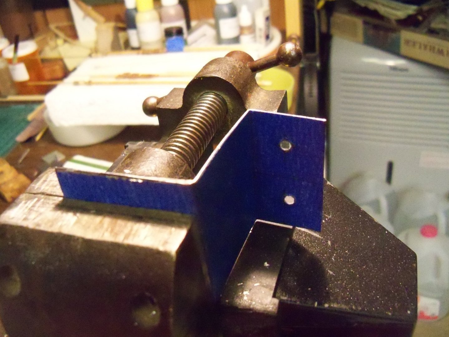
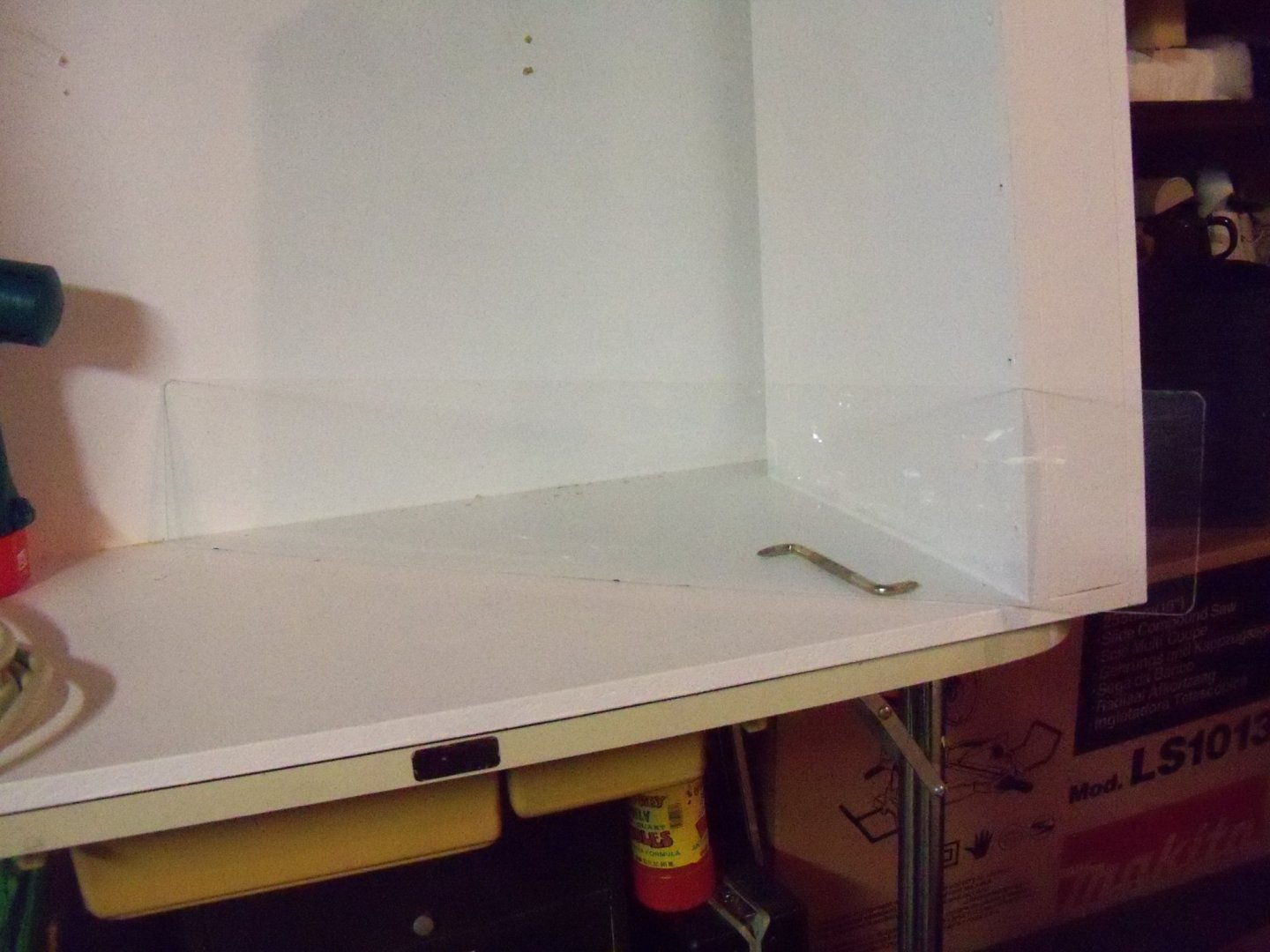
I sense that the completion of this project is finally in sight. Since I already had the booth on its backside, I wiped down the top edges of the panels and the self-adhesive backed foam weather-strip was applied. One thing to keep in mind while applying the weather-strip is to keep the backing tape on until just before it is pressed down because everything sticks to it, much like fly paper. Any dust or even oil from your fingers will reduce the effectiveness of the adhesive. When I applied it, a small portion of one end was exposed and pressed in place. Then with one hand used to lightly press it in place and keep it aligned with the edge, the other hand keeps pulling the backing tape off as you go along. After it’s in place I go along the entire tape length with a smooth tool handle, the foam is firmly pressed in place. The method works quite well for me. The top vinyl filter channel was given a double strip to keep it from twisting when installed. Since the foam needed to be compressed to half its thickness, the stove bolts would be under a bit of stress, I thought I would give the slotted end of the bolts a little more purchase with a washer. However, since this end of the bolt went into a countersunk hole, a flat washer wouldn’t work. The washer was fairly thin, so I made a sort of tool and die arrangement to make the washer conform to the hole. Drilling a matching hole into a ¾” piece of oak complete with the countersink for the die, a matching bolt was set into the die hole with the flat washer in place. Taking a one handed sledge hammer, I simply pounded the bolt down into the die until it conformed to the shape of the countersink. Seven more washers were made up similarly. Eight of the bolts, complete with washers were now placed in the booth with the threaded ends projecting from the backside of the booth. Tipping the booth back upright, a difficult job for one person to handle, reattaching the top panel, began. First off, the foam needed to be compressed to half its thickness to allow the projecting ends of the bolts to align with the hinge holes. Placing the bar clamp next to the hinge on the end, I tightened the clamp until the two bolts aligned with the hinge holes. The next step had me puzzled for a bit, namely how to tighten the bolt when I could only reach one end of the bolt at a time by myself. I solved this by clamping the nut in the jaws of a small pair of vise grip pliers. Now I was able to reach inside the booth with a straight slot screw driver. With the resistance provided by the weight of the pliers, I was able to tighten the bolt. This method was repeated for three hinges, but the last hinge was a slightly more difficult problem, in that the plenum framing would not allow me to reach through the booth to reach the bolt with the screw driver. Once again I used the bar clamp to align the bolts with the hinge and loosely installed the washer and nut to keep the foam compressed. Tilting the booth down on its backside once again, the top panel was allowed to drop down leaving me access to the inside of the booth and the slotted end of the last two bolts. I tried several methods of doing these last two bolts but was unable to keep the bolt from turning with the nut until I sort of discovered by accident an easy way to do it. Inserting a nut driver in my impact driver, I set it on the nut and kind of goosed the trigger several times. To my surprise, it actually worked. Apparently the combination of the twisting motion when combined with the impact motion kept the bolt from turning in place and it tightened it down quite solid. I could have saved a bit of hassle if I had realized it would do that with all the bolts! Oh well, live and learn. Tilting the booth upright again, I took a photo of its current status.


-
Homemade Spray Booth
BETAQDAVE replied to BETAQDAVE's topic in Modeling tools and Workshop Equipment
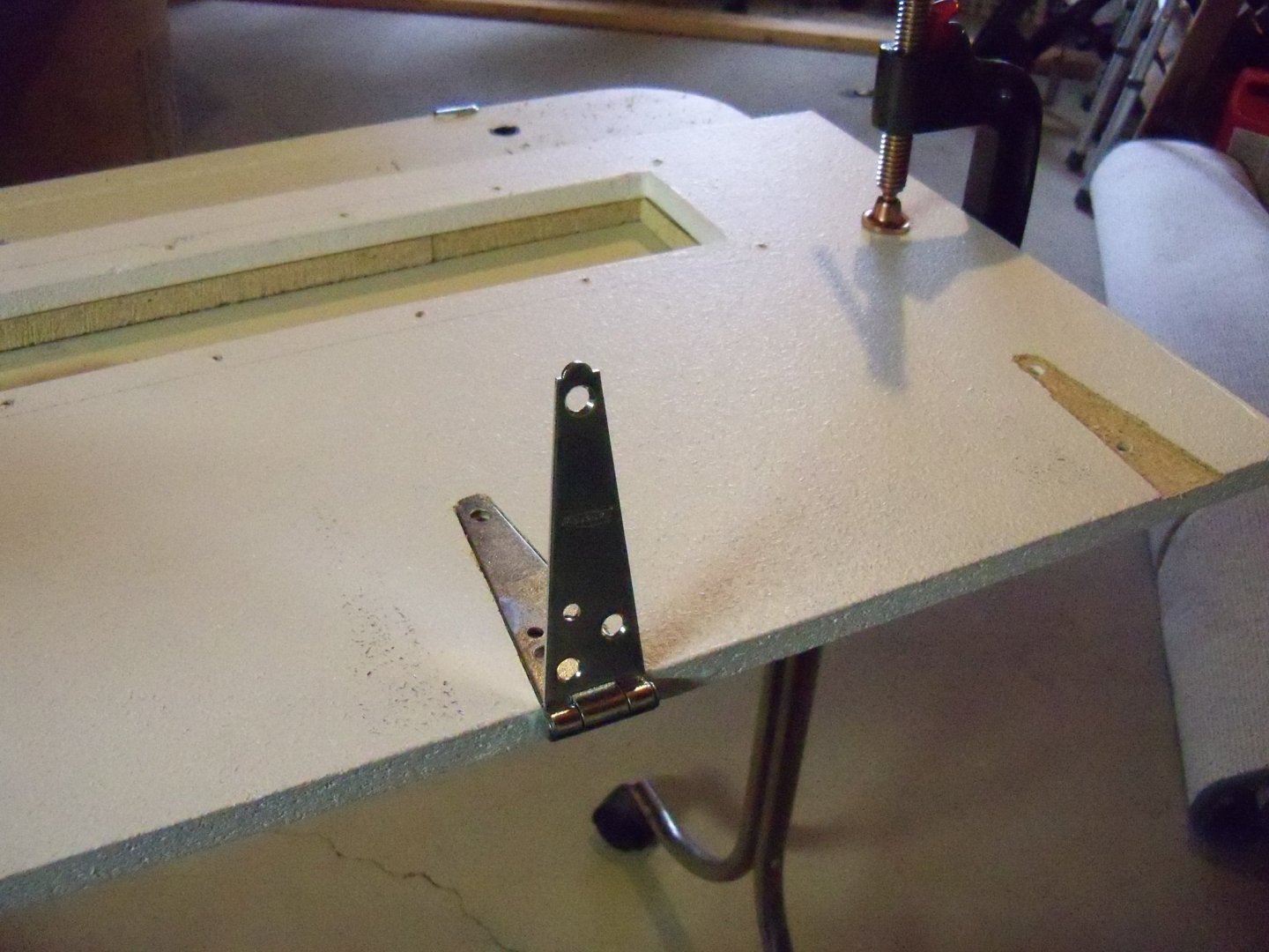
Well, time to start sanding down the top edges of the booth panels. Glue has set and all of the tape “clamps” have been removed. Taking a three foot long length of a straight edged 1 x 4, I glued a 12 inch long piece of 100 grit sandpaper to opposite ends of that boards’ edge. The center portion was covered with a section of heavy manila envelope approximately equal in thickness to the sandpaper. Then resting the center section on the top of the baffle panel and the sandpaper on the two raised panels, I just kept sliding the center across the baffle until the sandpaper ground the rear and right side panels down to equal heights. That was the area with the most to even out, the rest was simply using a sanding block and a straight edge to check on the progress until it was all evened out. This whole sanding operation only took about an hour to do, so I was happy that I decided to do it this way. Tipping the booth upright, the top panel was mounted by ripping several narrow pieces of 1/8” thick hardboard to use as spacers and I set them on the top edges of the panels. The top panel was then placed on top and clamped down with a bar clamp to secure it. Using the hinges as templates, the new locations for the bolts were marked with an awl and the holes were drilled. The holes were counter sunk on the inside of the booth with an overlong 3/8” drill bit as the new brace and the filter channels made it too difficult to get my drill in position to use my counter sink bit. The booth was unclamped and top panel was then removed. All of the unpainted parts of the booth were then given two quick coats of paint and left to dry overnight.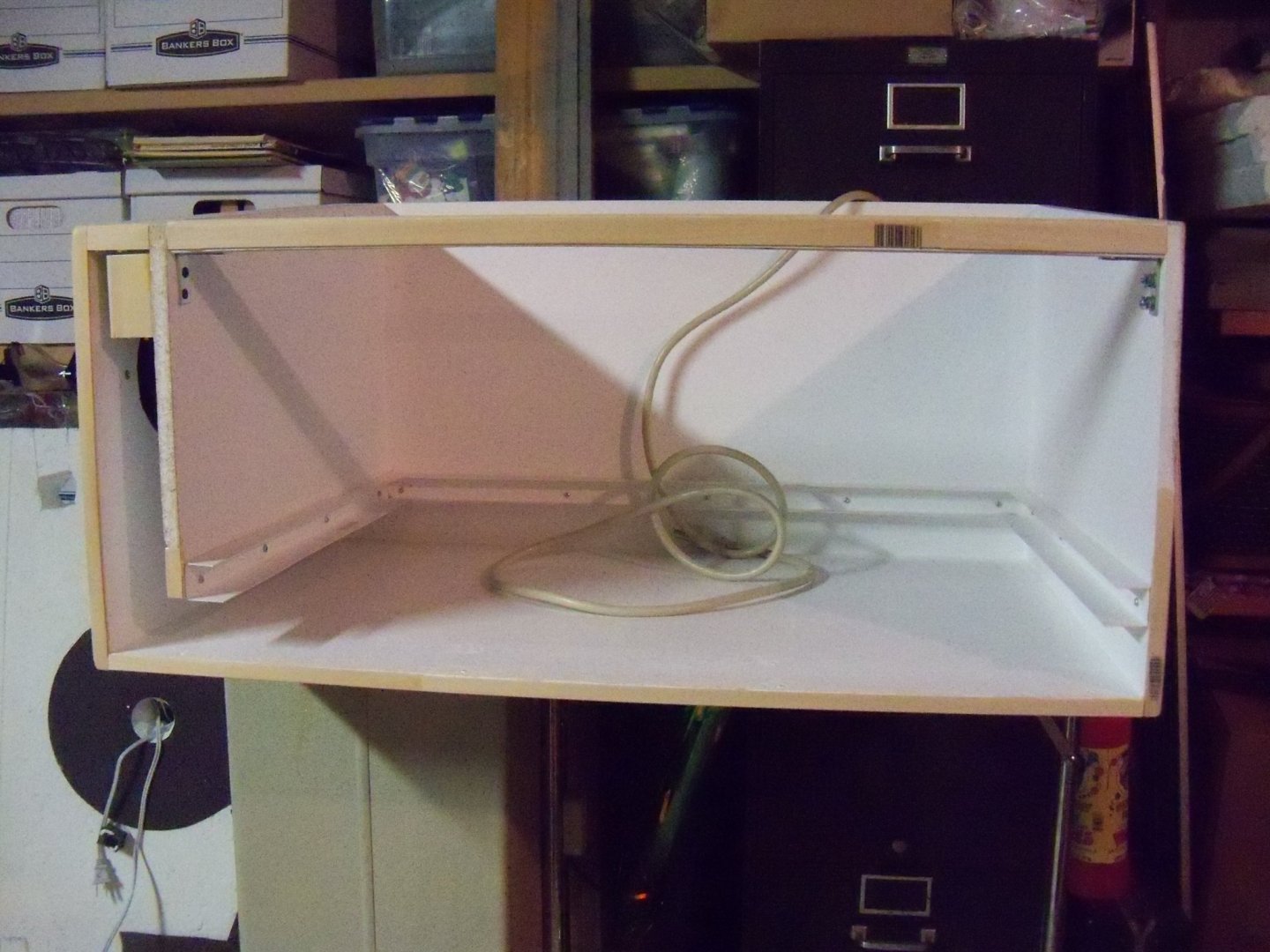

-
Homemade Spray Booth
BETAQDAVE replied to BETAQDAVE's topic in Modeling tools and Workshop Equipment
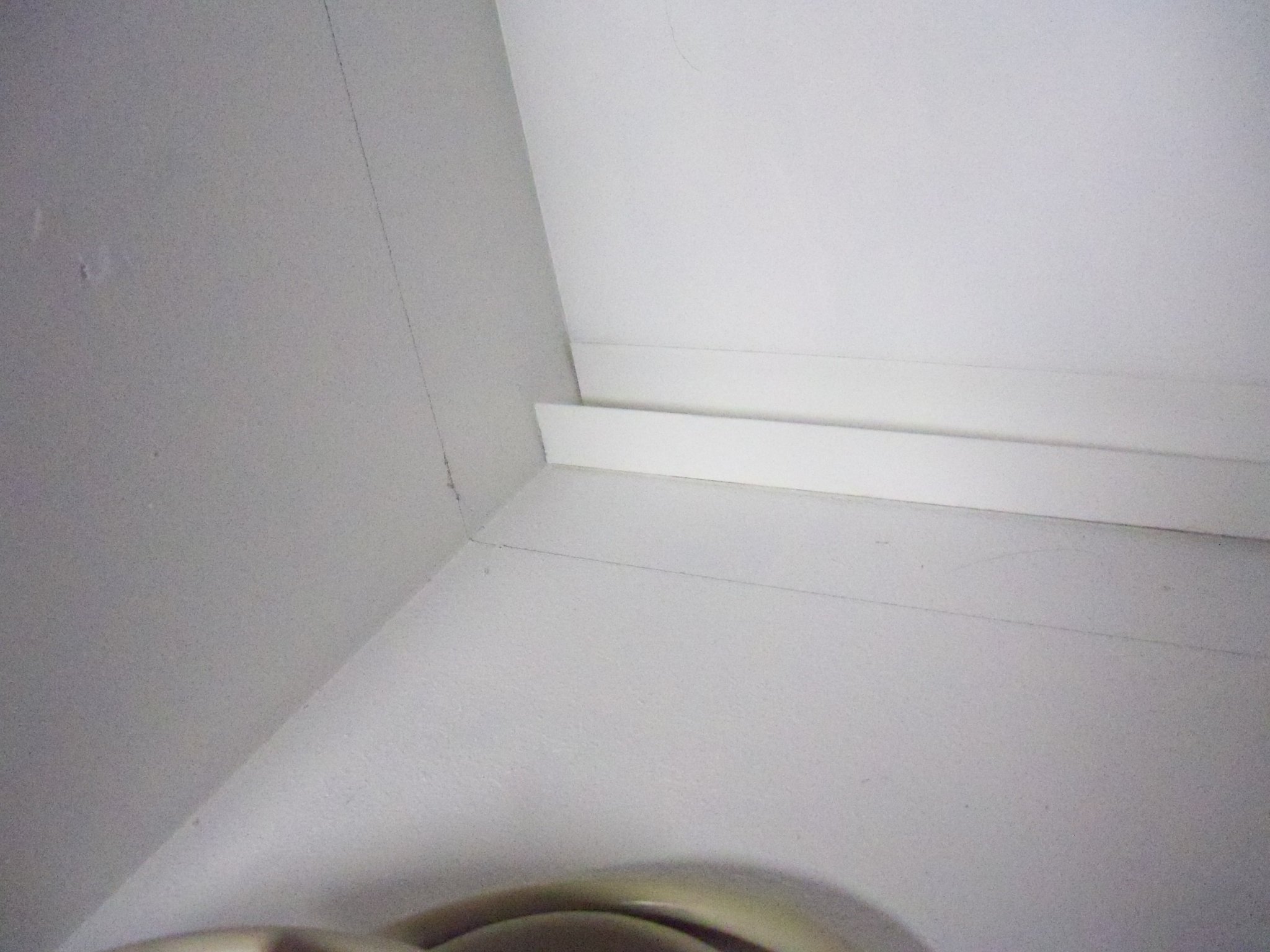
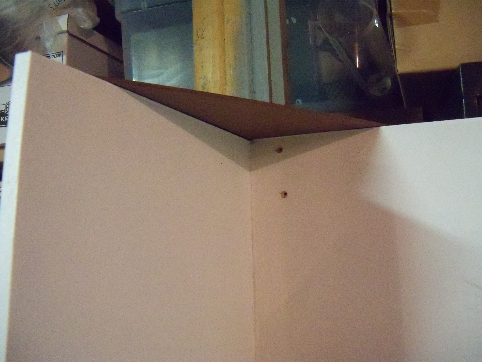
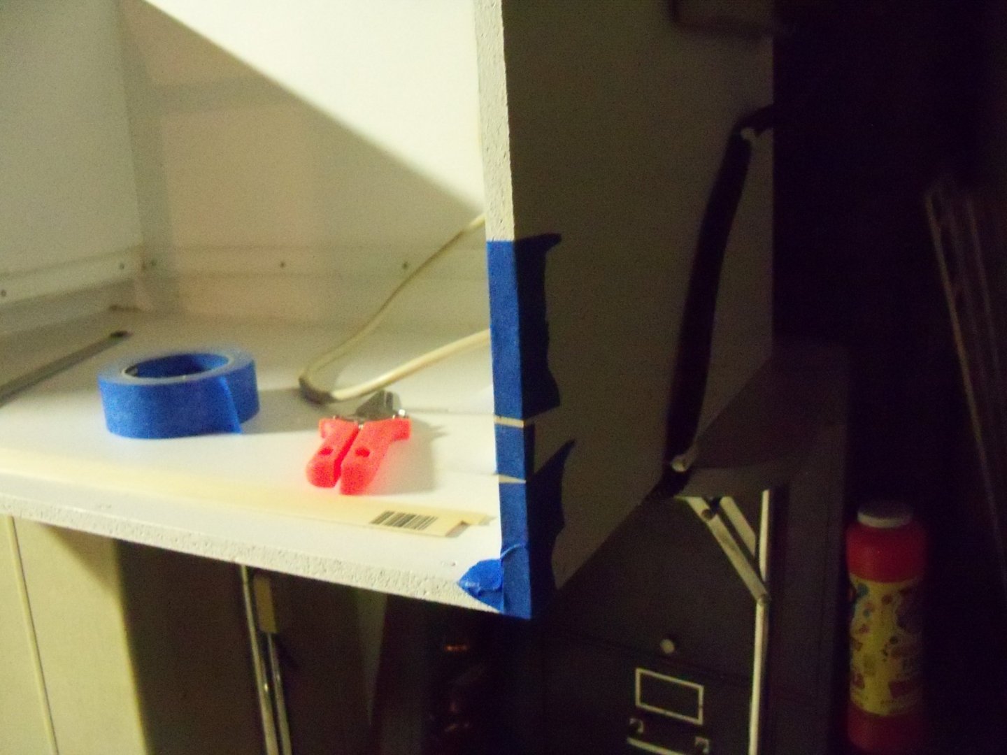
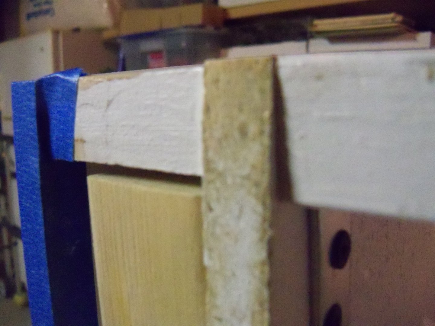
Hold the phone there dummy! What was I thinking? Why try paring down the tough particle board when it’s much easier to add some softwood shims that can then be lightly sanded down even? Having a large surplus of 1/16” thick basswood strip wood in various widths, that’s just what I did! I took a long flat metal bar and laid it along the top edges of the booth to locate and measure the problem areas. The biggest discrepancy occurred where the top edge of the baffle panel sat a hair over 3/32” above the right side panel and about 1/16” above the back panel. The back corner of the left side panel sat about 1/16” shy of the top of the joint with the back panel, so I can use a tapered shim there. The back corner of the baffle was actually a little low also and needed a bit of shimming. I took a length of ½” wide 1/16” thick basswood and glued it to the top of the right side panel for the first of two layers to go there. Not having any edge clamps available, I resorted to taping it in place. The low corners of the baffle and the left side panel were also given short lengths of tapered shim to correct those areas and were glued and taped down. You can see here that the front brace was also depressed a bit, and while there is no concern of air leakage there, if left shy the top panel would not sit flat. So that needed to be shimmed too. A single layer of the 1/16” basswood sufficed to shim up most of the errors, and an extra layer handled the remaining areas. A second layer of 1/16” shim was now added to the right end panel and applied. The back panel and brace were then done similarly. Now with all areas shimmed and taped down, I just needed to set the booth aside for the glue to set up for 24 hours or so before starting sanding operations.

-
Homemade Spray Booth
BETAQDAVE replied to BETAQDAVE's topic in Modeling tools and Workshop Equipment
Just a quick note here. Now that the hinges are correctly attached to the bottom side of the top panel, the hinges need to be re-attached to the back panel. Since the weather-stripping came in ¼” thickness rather than the 3/8” that I ordered, I was a bit concerned about the air seal at the top of the booth. So I checked the fit of the top panel and found that some of the top edges were a little too uneven for my taste where the panels met. Since the weather-stripping is so thin now I don’t think that it would be able to bridge the gap enough, so I need to trim down those high areas. The most efficient method available to me would have been my belt sander, but I don’t think that I would be able to handle that anymore from my wheelchair. (Not to mention the clouds of saw dust that it would produce!) Edge trimming ½” particle board will take some ingenuity on my part keeping the edge square and smooth by hand without breaking up the edges. I guess that I will have to think on that for awhile. -
Homemade Spray Booth
BETAQDAVE replied to BETAQDAVE's topic in Modeling tools and Workshop Equipment
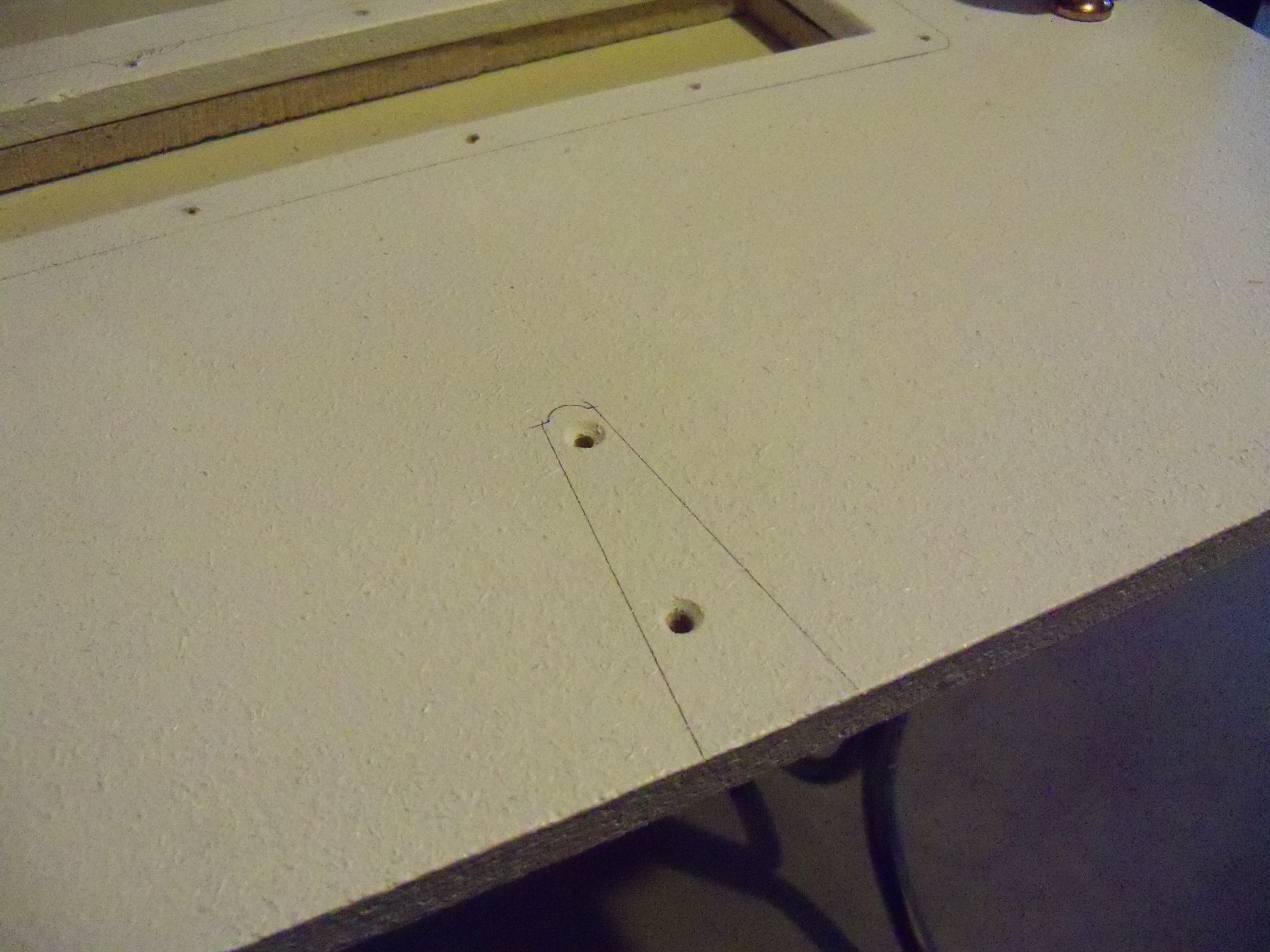
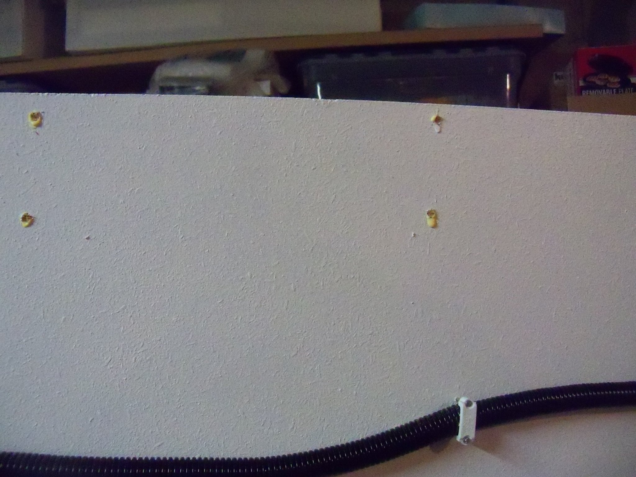
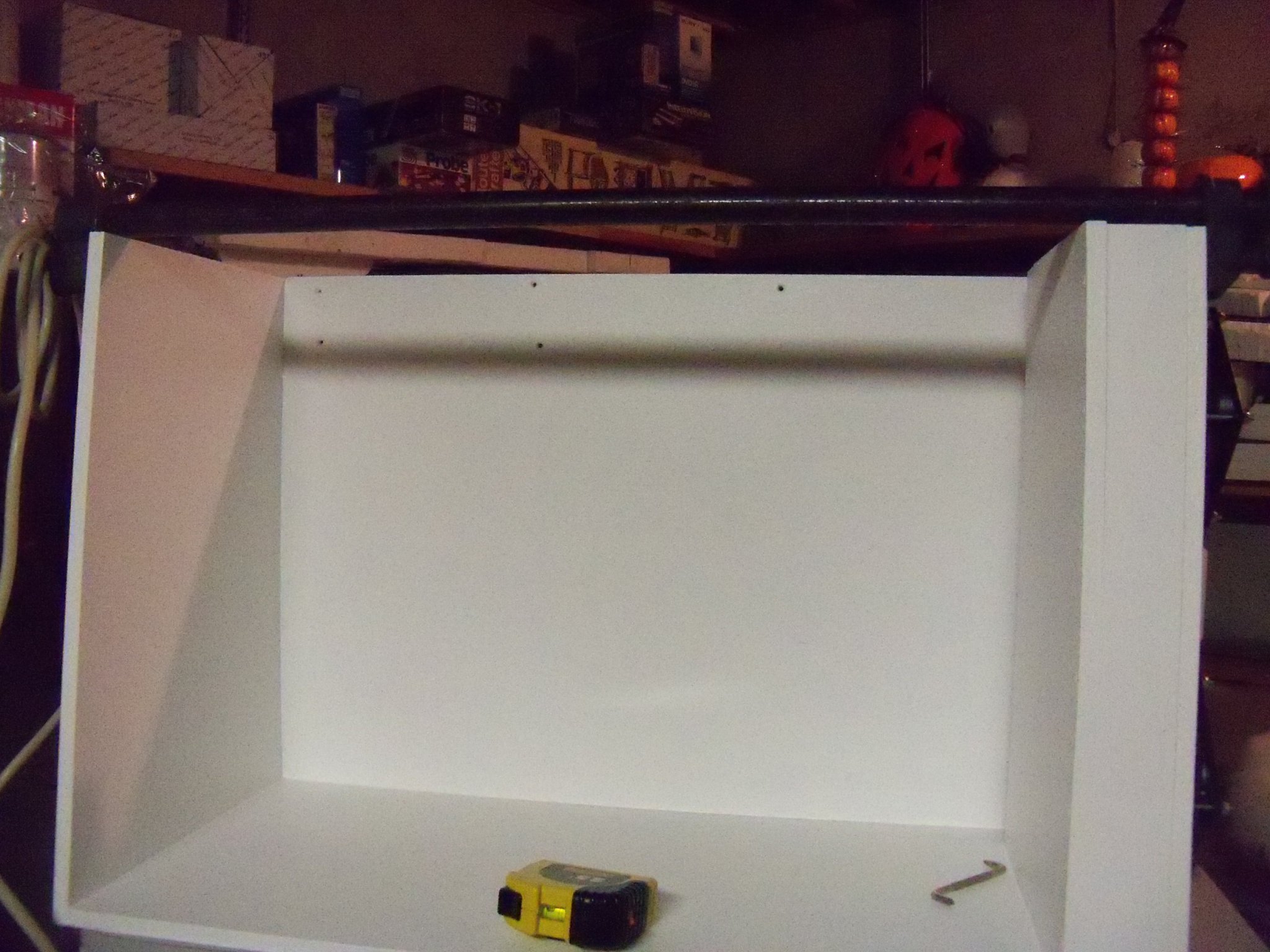
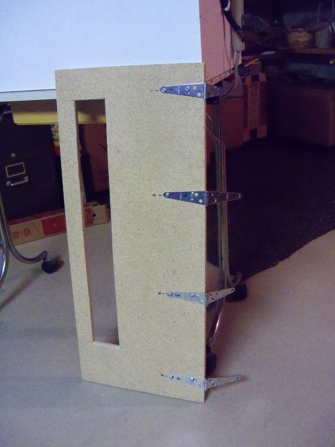
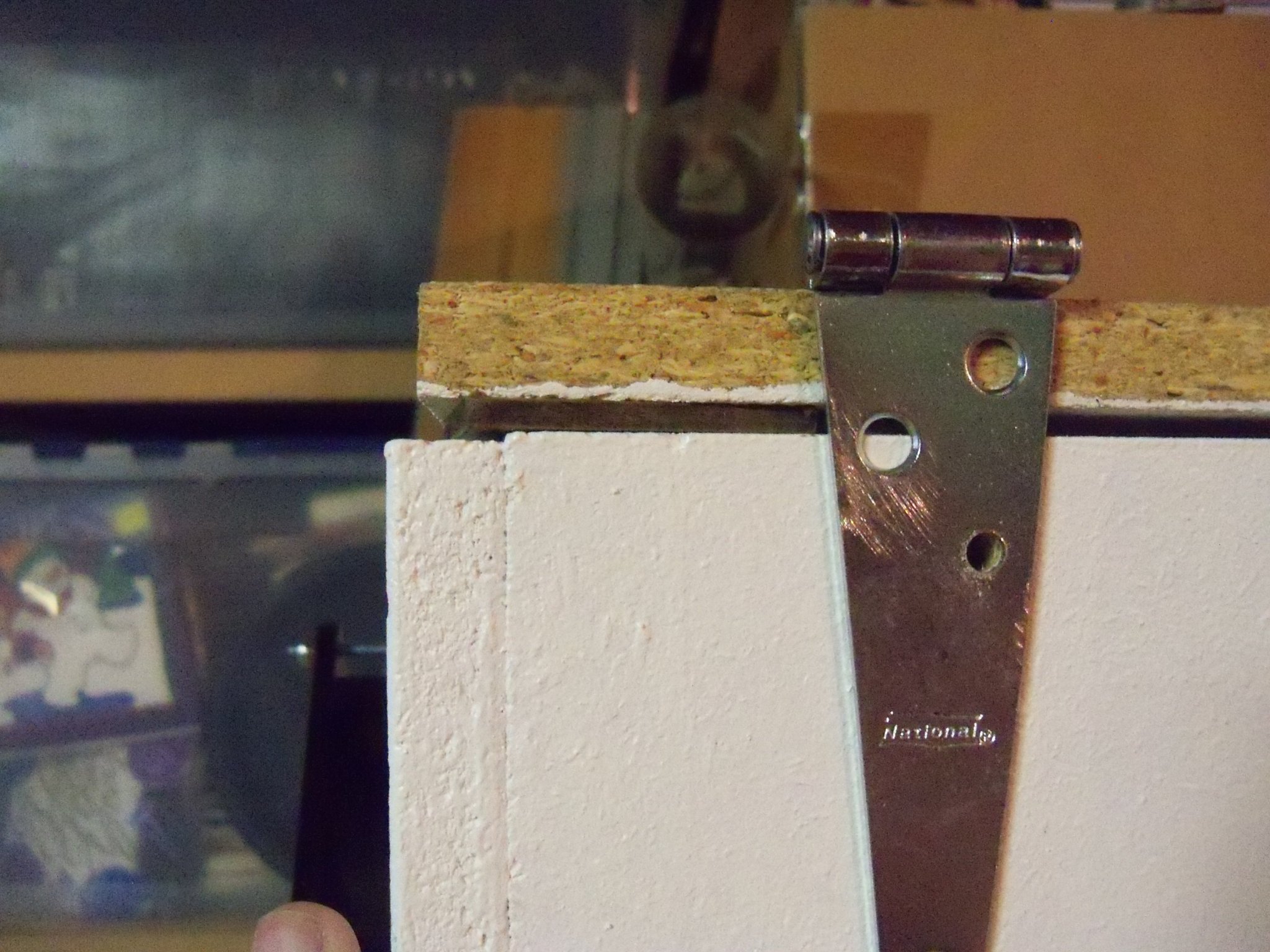
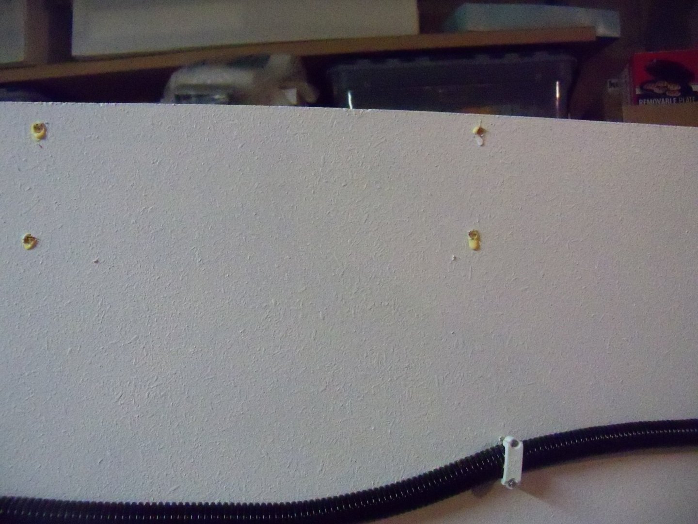
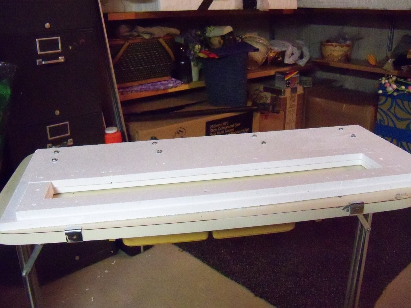
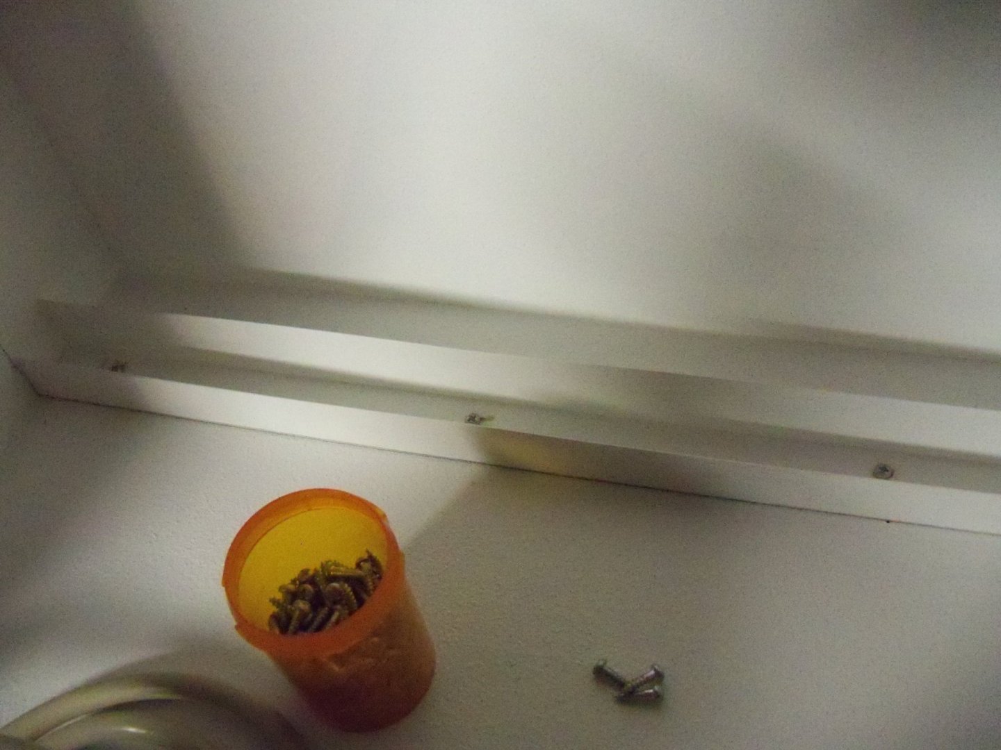
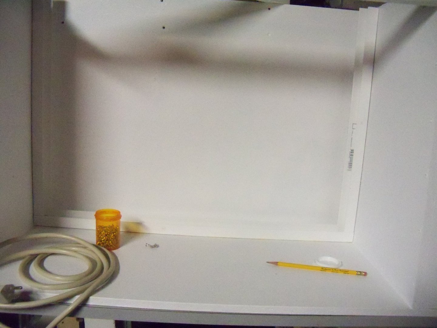
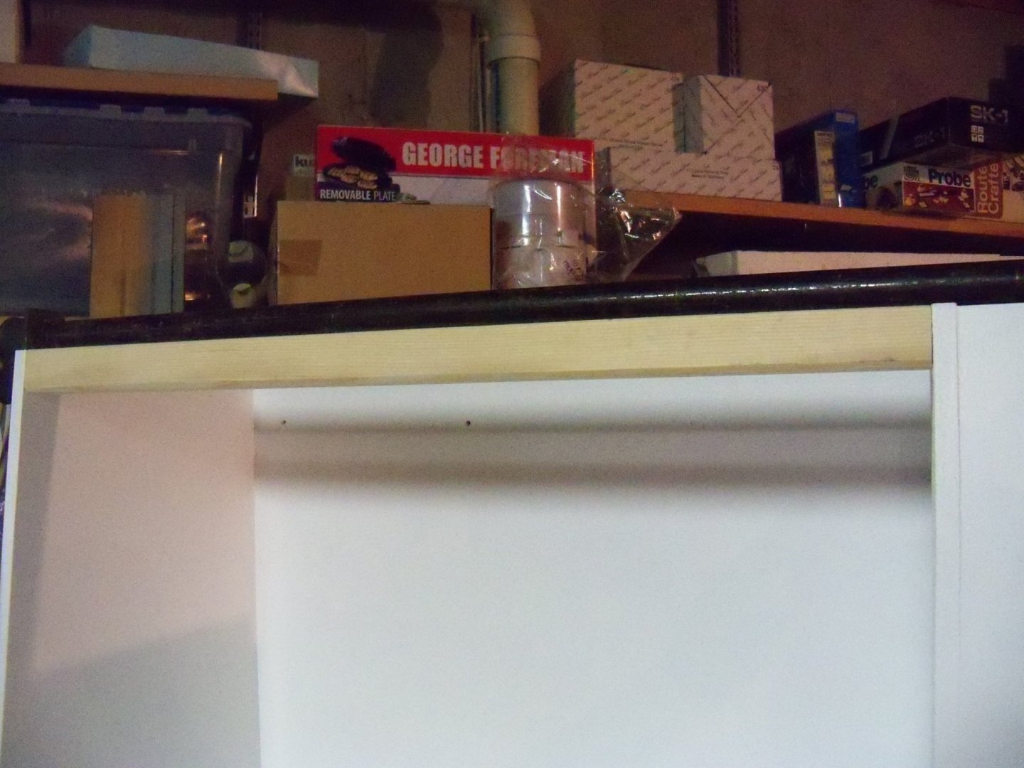
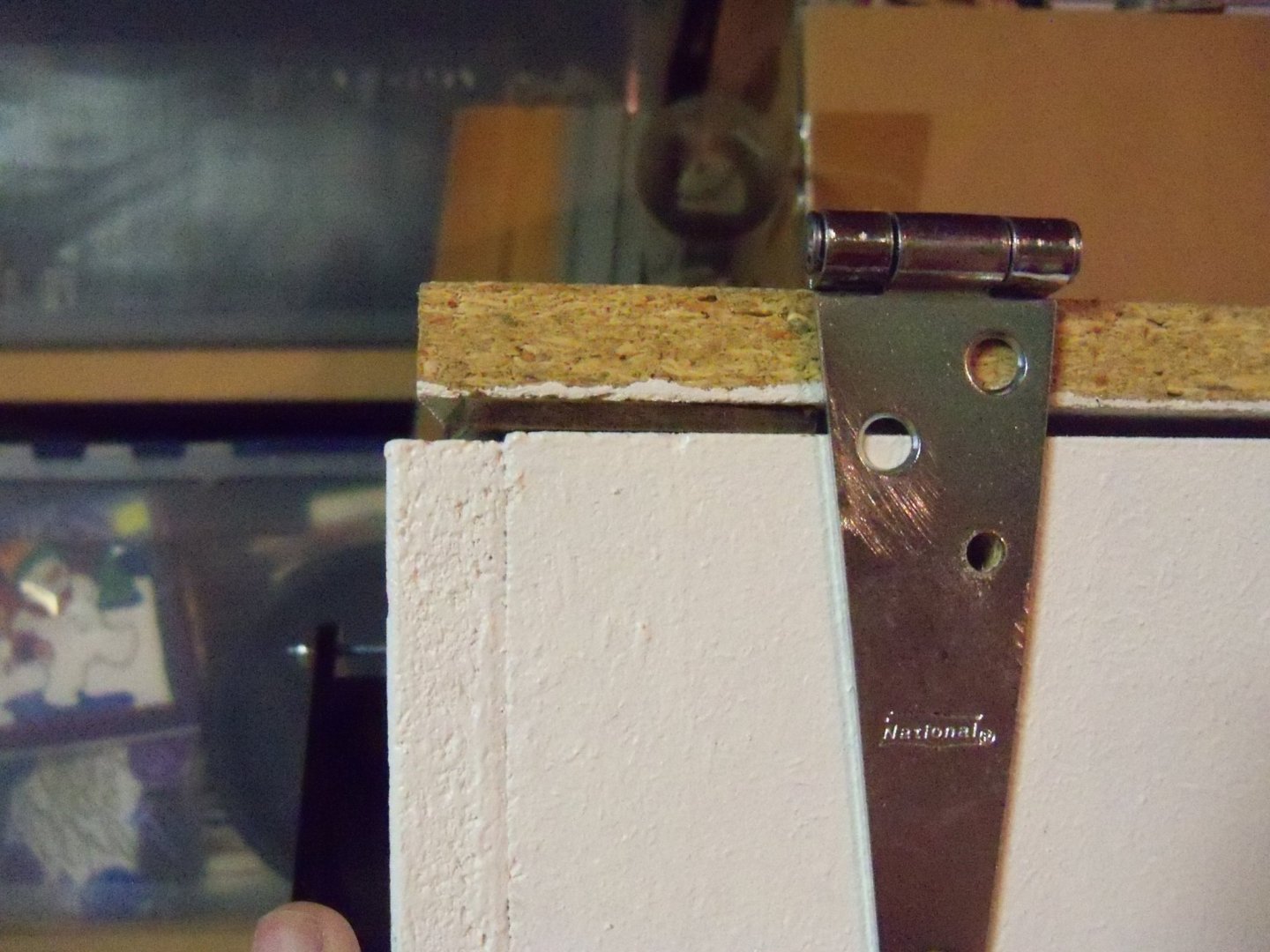
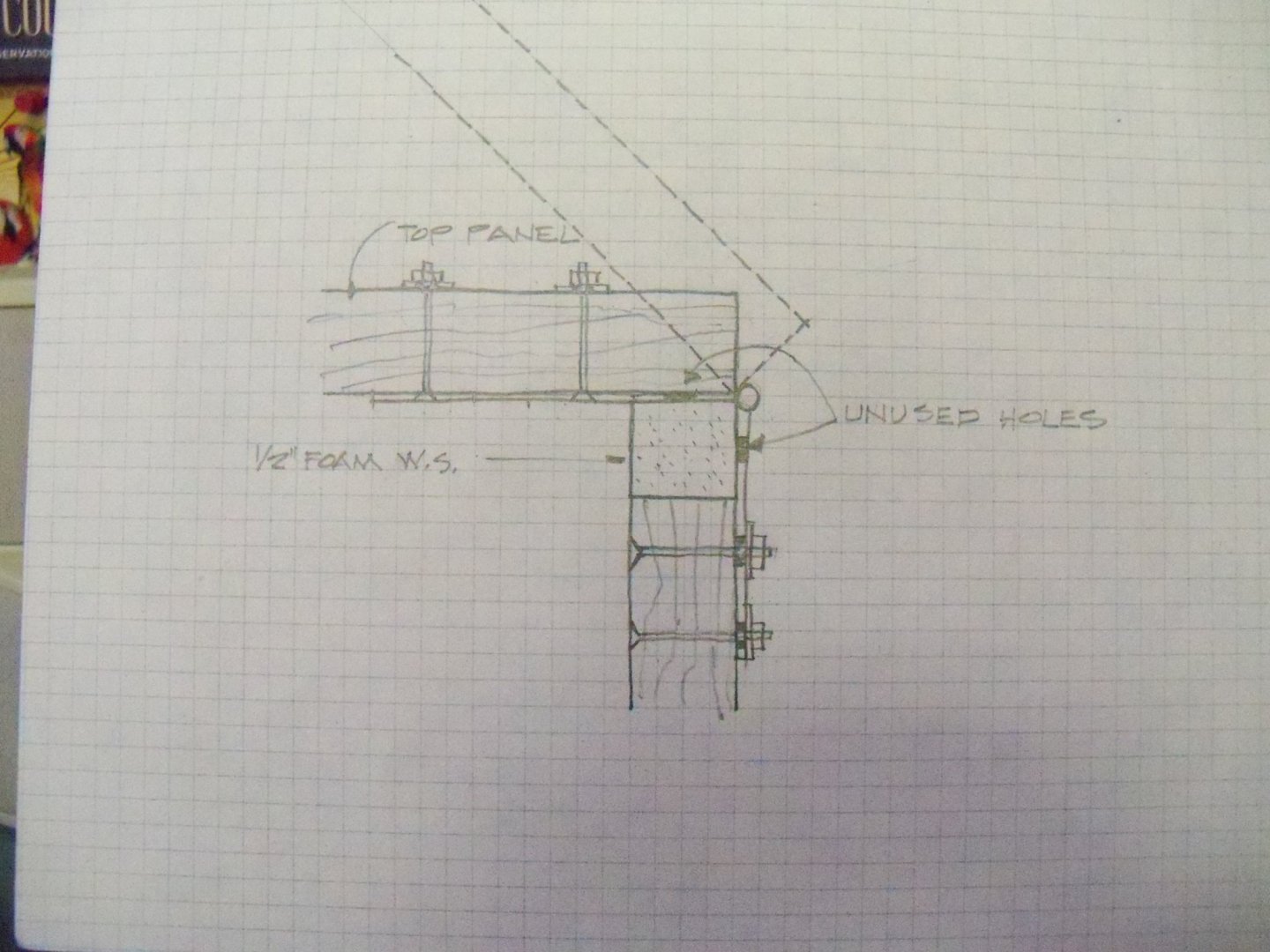
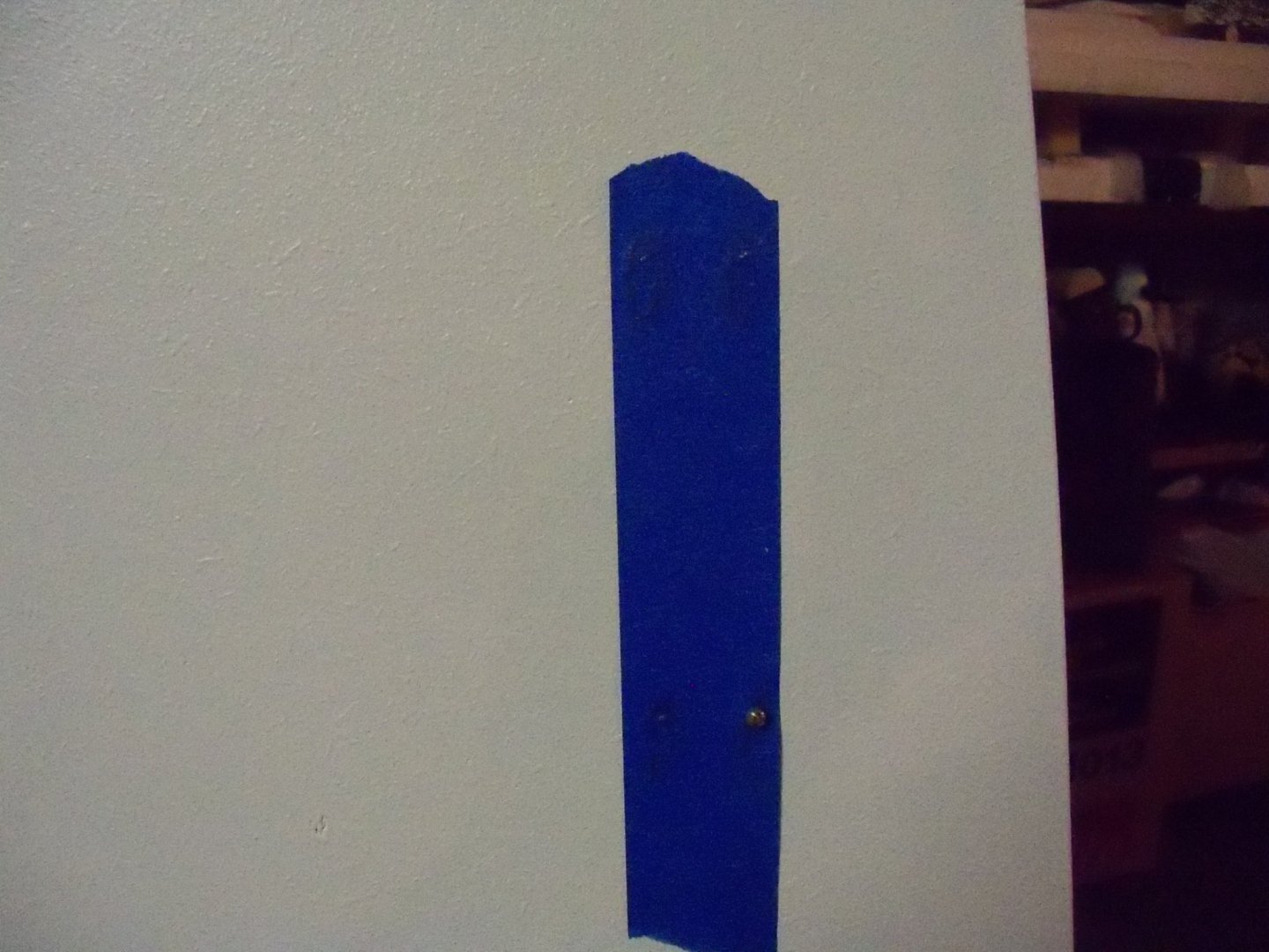
Continuing my rainy day posting. While contemplating my next phase of the build, I discovered while reviewing post #20, that the hinges were placed in error on the top side of the top panel, which in itself was not a big deal as far as the placement of those holes, but it caused another problem elsewhere. The original idea was to have the pivot point of the hinges half the thickness of the compressed weather-strip above the top edge of the back panel as shown in post #19. That was to prevent the weather-striping along the top of the back panel from being displaced when opening the top of the booth. Since the hinges were used as a template for drilling the holes on the back panel, those holes were now 5/8” too high. OOPS! Flipping the top panel over to expose the correct side of the panel, the Plexiglas window was removed and set aside for installing the tear off sheets later. The hinges were then temporarily attached to the bottom side of the top panel and the outline of the hinges was traced onto the panel as shown here. Since this will now be the inside of the booth, I decided that making the hinges flush with the surface would improve the air flow. Taking the hinges off again, I took out a fresh sharp blade and put it into my scalpel handle to go over the marked outline several times. I took a ¼” wide wood chisel and gave it a good sharpening. I roughed out the majority of the material with that chisel and one of my small modeling chisels. I then finished up with my Dremel tool mounted in a homemade router attachment and smoothed out the bottom of the recess to the proper depth. Since the screw holes in back panel would no longer line up, those holes needed to be plugged. I took a length of 3/16” square basswood, rounded off the corners, coated with wood glue and tapped it into those holes until the far end was slightly beyond flush with the inside of the booth. I cut off the remaining length on the outside slightly proud of the outside face. This was repeated for all of the remaining holes. Once the glue was allowed to set, the remaining ends of the plugs were sanded flush. A quick dab of paint and no one is the wiser. The recesses for the hinges were also given a coat of paint to seal the particle board and the hinges were reattached to complete the repairs. The inside of the plugs were also painted and a heavy coat of paint was applied to the seam of the vinyl brackets to give me a tight air seal around the filter assembly. The final item to be completed today was painting the light mounting boards sealing all joints to completely eliminate all the extraneous light at the joints.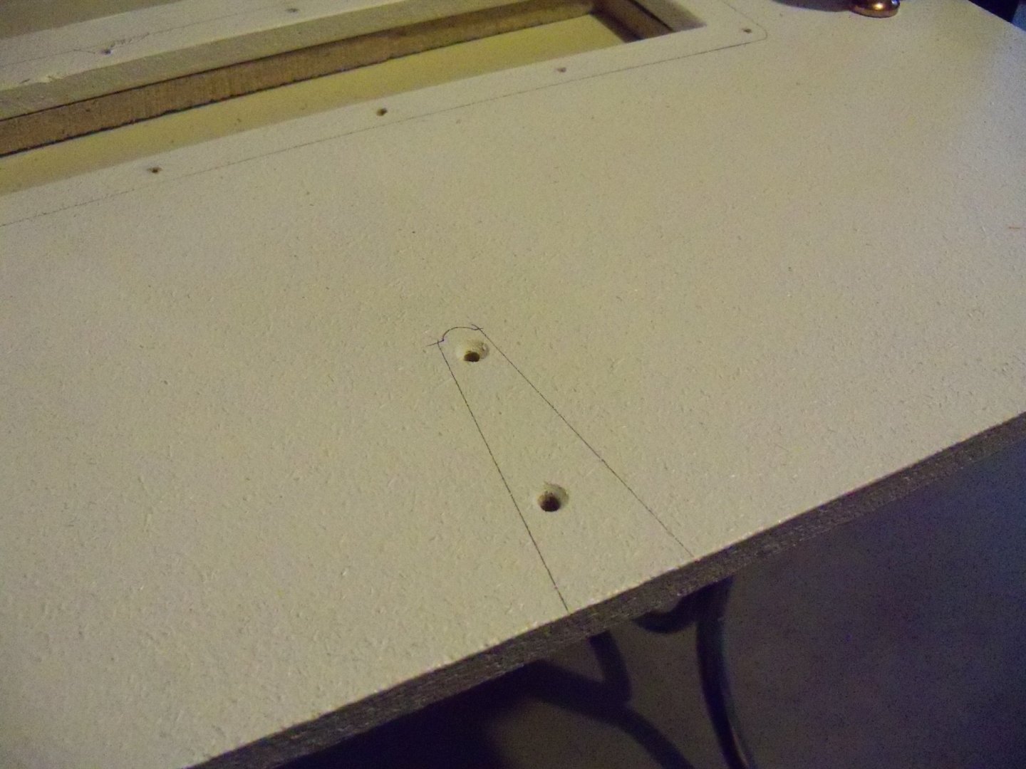


-
Homemade Spray Booth
BETAQDAVE replied to BETAQDAVE's topic in Modeling tools and Workshop Equipment
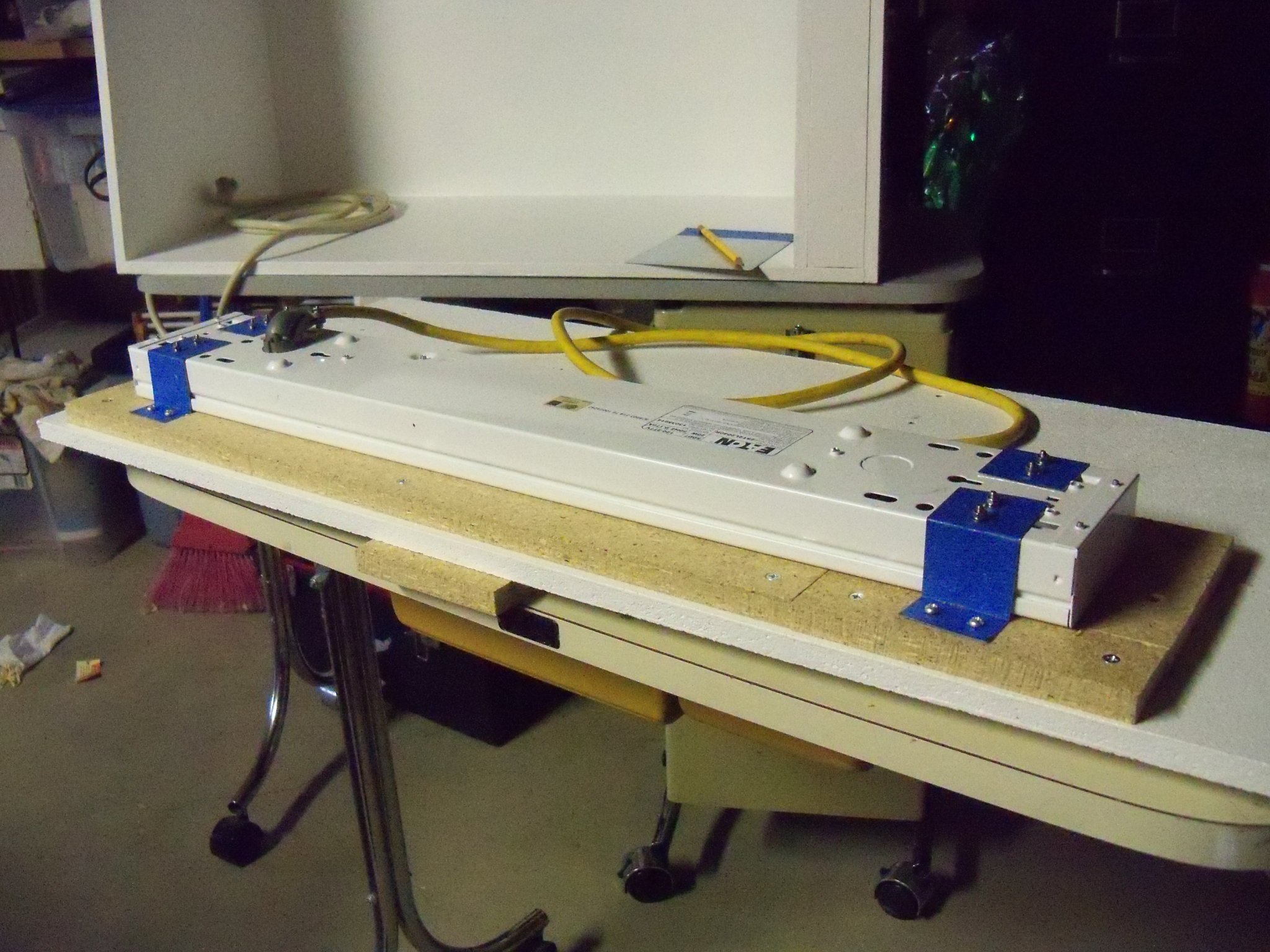
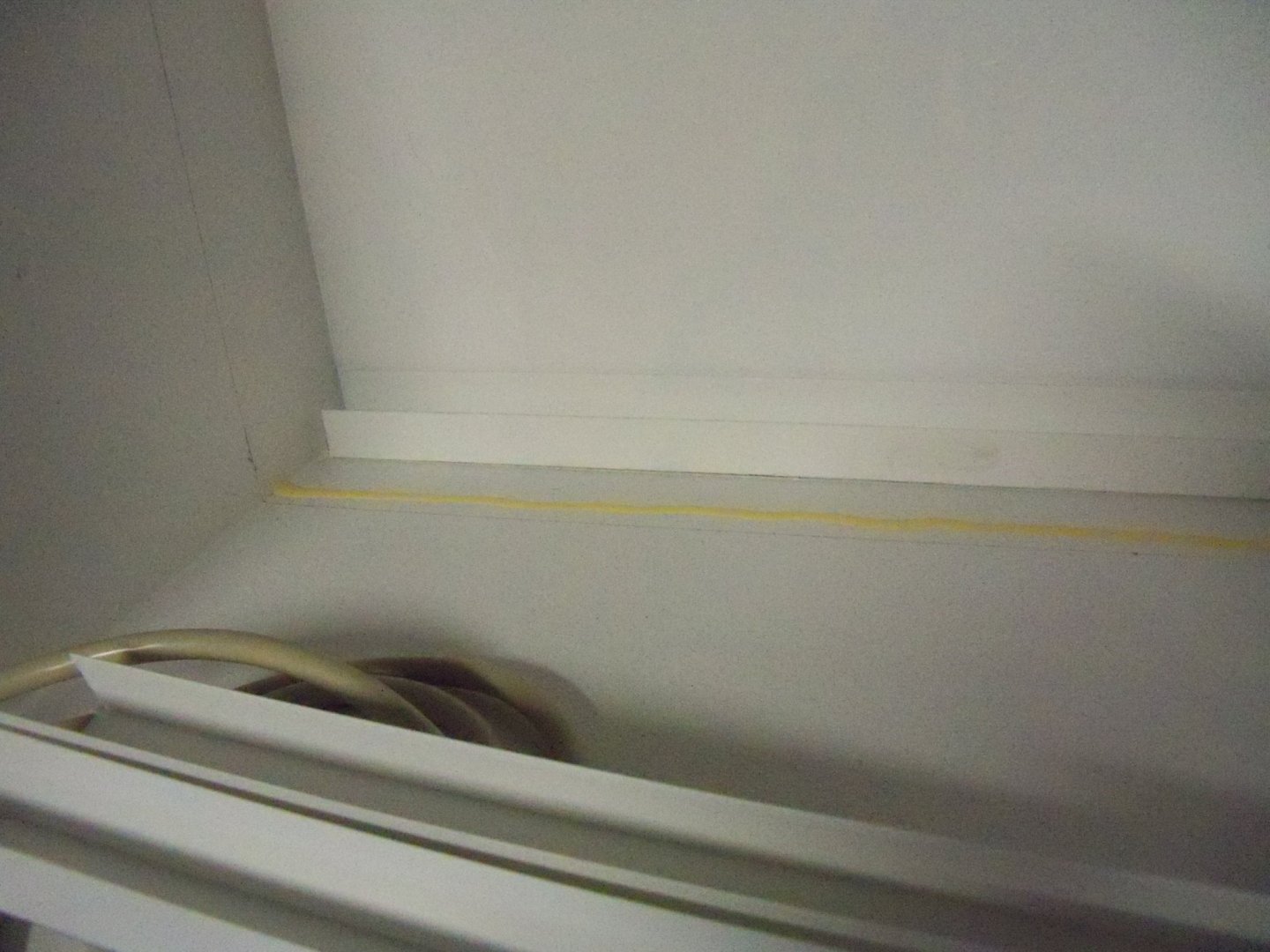
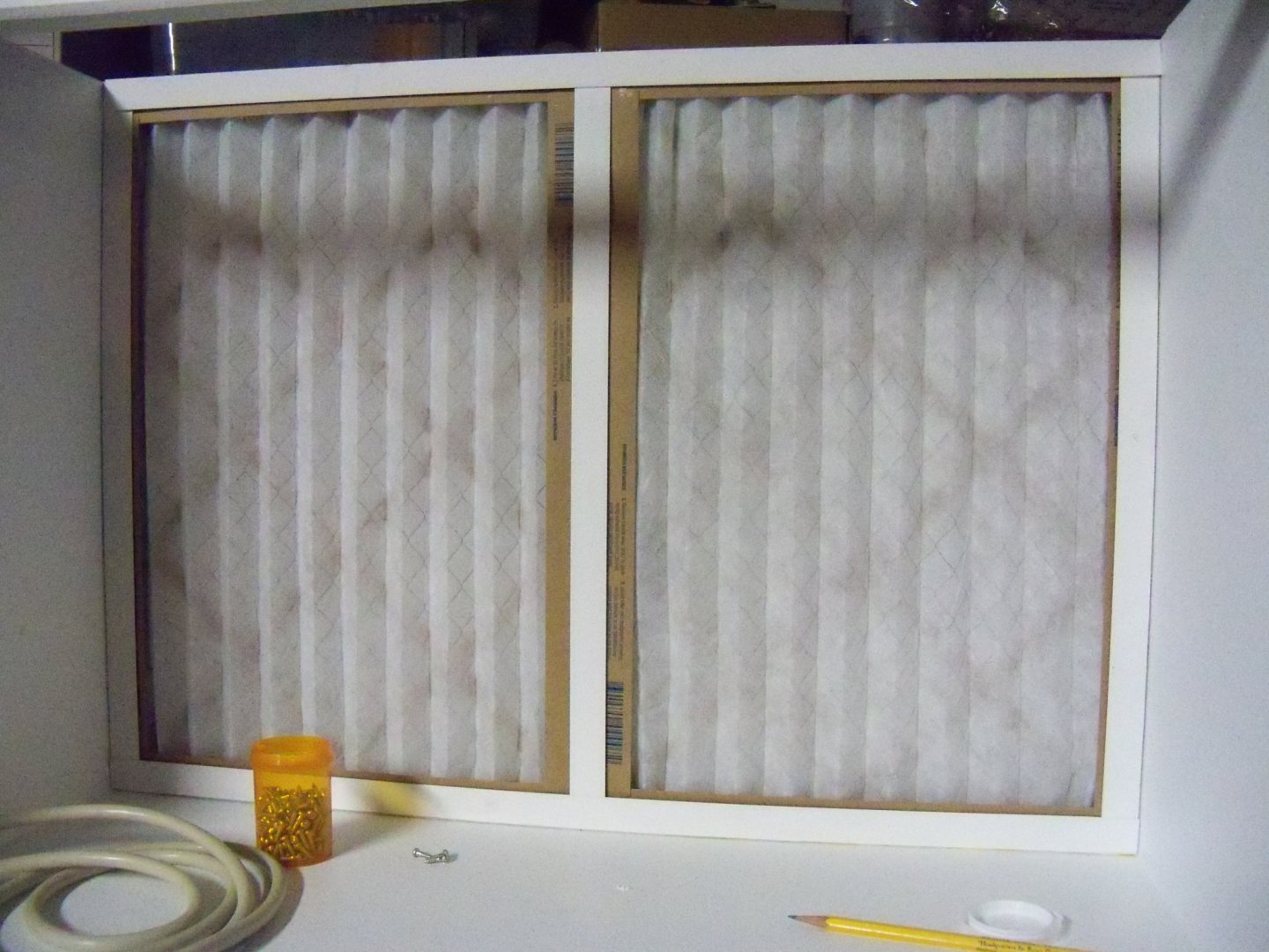
Since it's raining today looks like I get to work indoors again today, so back to the shop. I ripped down some of my scrap ½” particle board into several 1 ½” wide strips to make the mounting board for the light fixture. These were then cut to length, tightly butted together (to screen off any extraneous light) and screwed into place with some ¾” Philips flat head wood screws. I set the light fixture in the opening and used the pre-drilled holes in the brackets as a guide to locate and drill 7/64” holes for some ½” long 9/64” Phillips round head wood screws that were then driven home. The lines were redrawn inside the booth to mark the face of the vinyl filter brackets. I ran a bead of glue where the vinyl bracket would seat to help seal the gap somewhat. Before the glue could set, the vinyl strip was placed and I drilled five 7/64” holes into the bottom of the booth for some more of the ½” long 9/64” wood screws to draw it down tight. Using four screws apiece, this procedure was followed for the two vertical vinyl brackets. Once the vinyl brackets were all installed, I did a test fit for the rest of the filter assembly and was satisfied with the fit.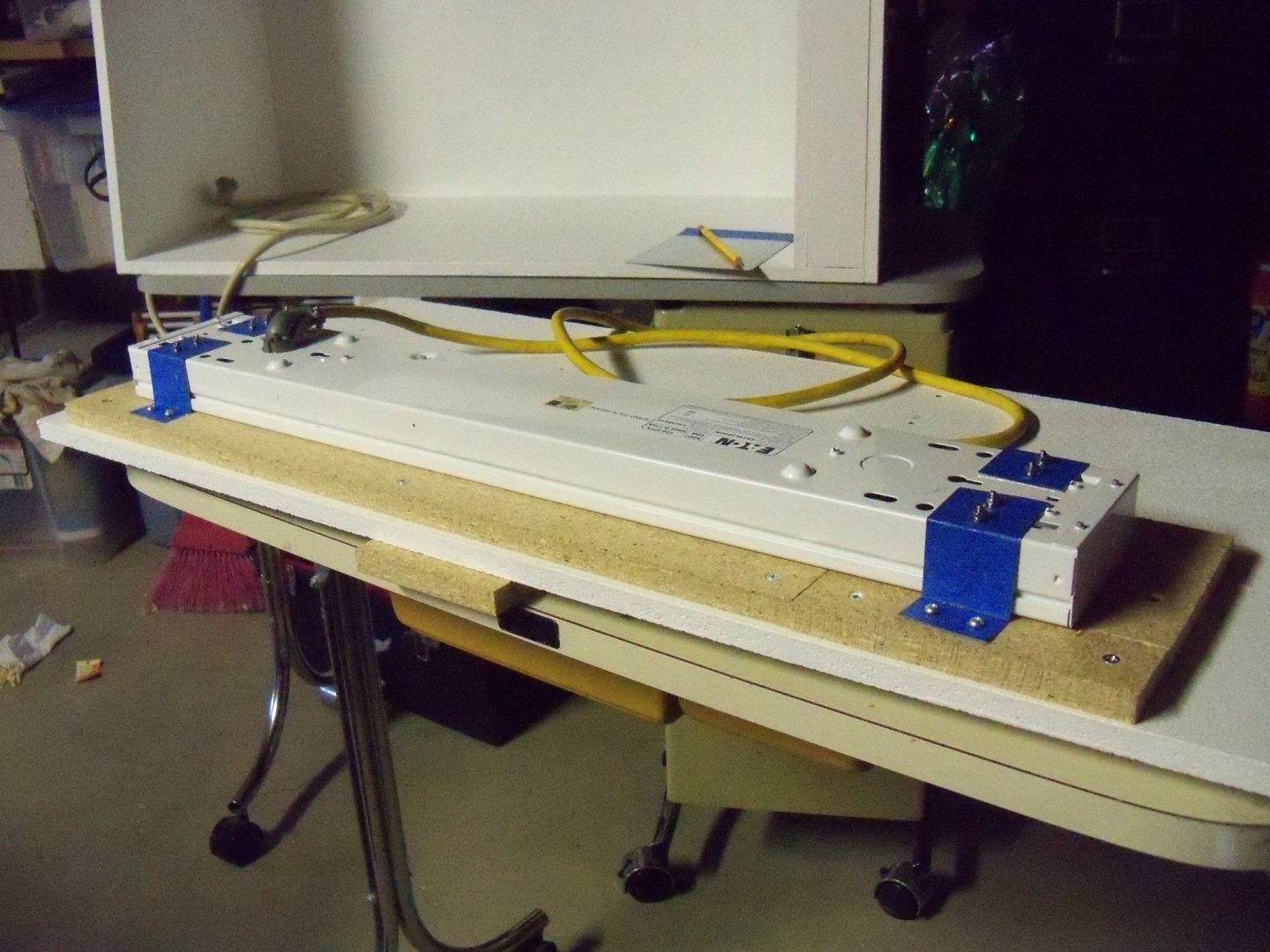

-
Homemade Spray Booth
BETAQDAVE replied to BETAQDAVE's topic in Modeling tools and Workshop Equipment
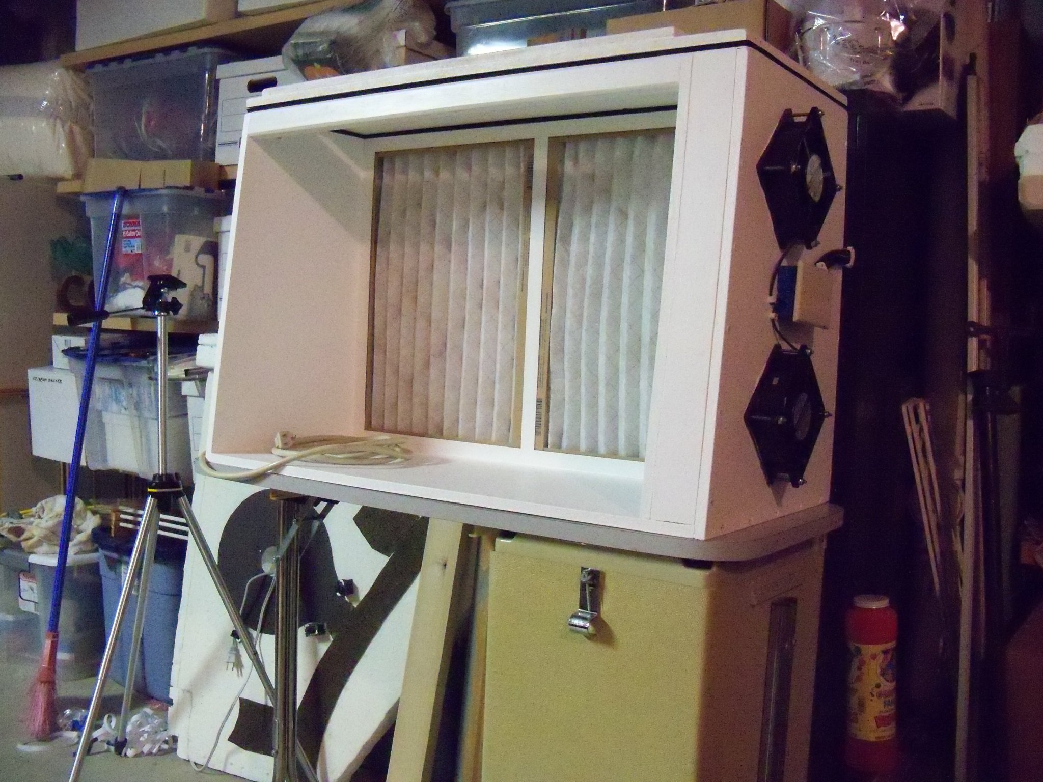
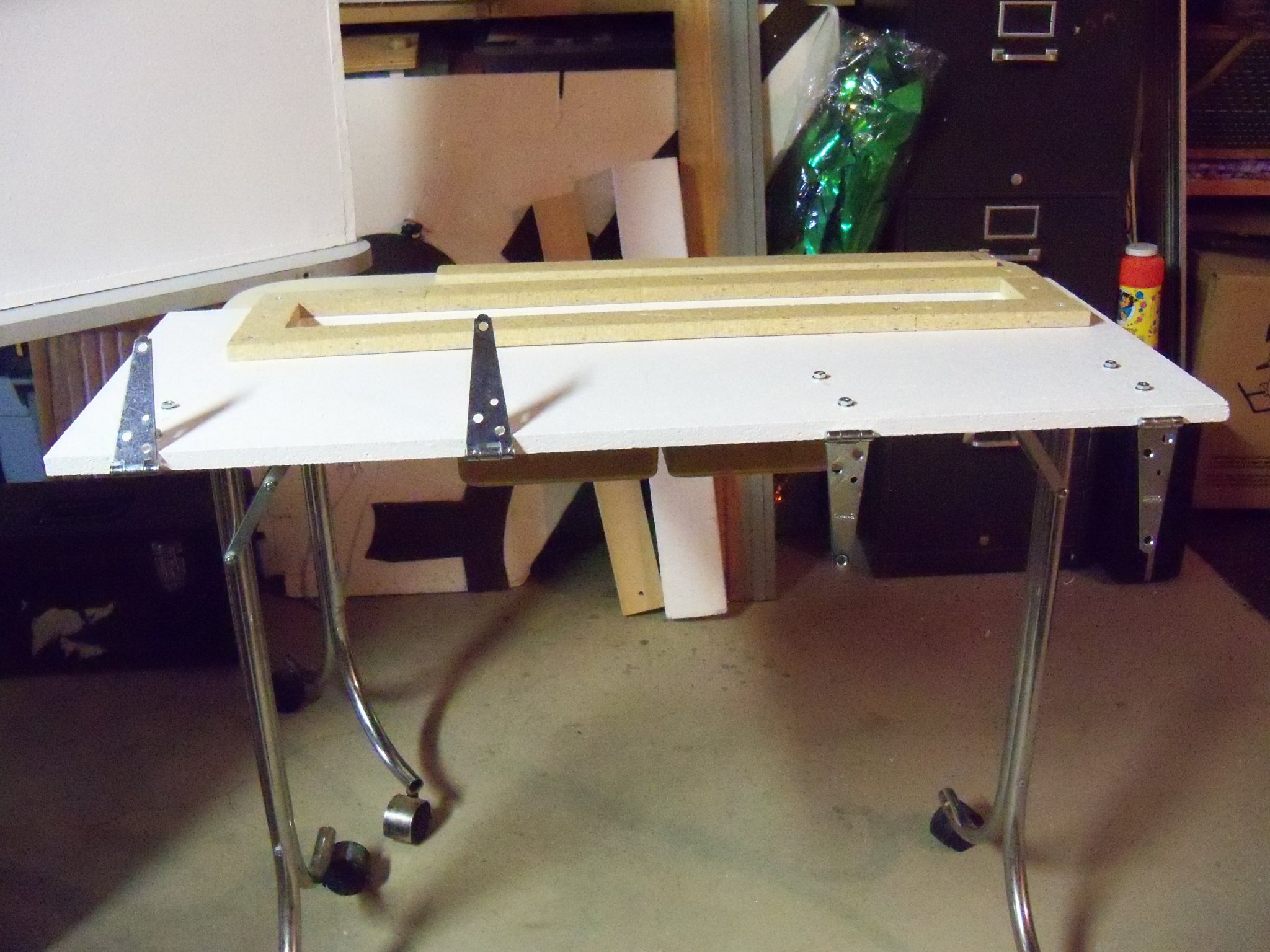
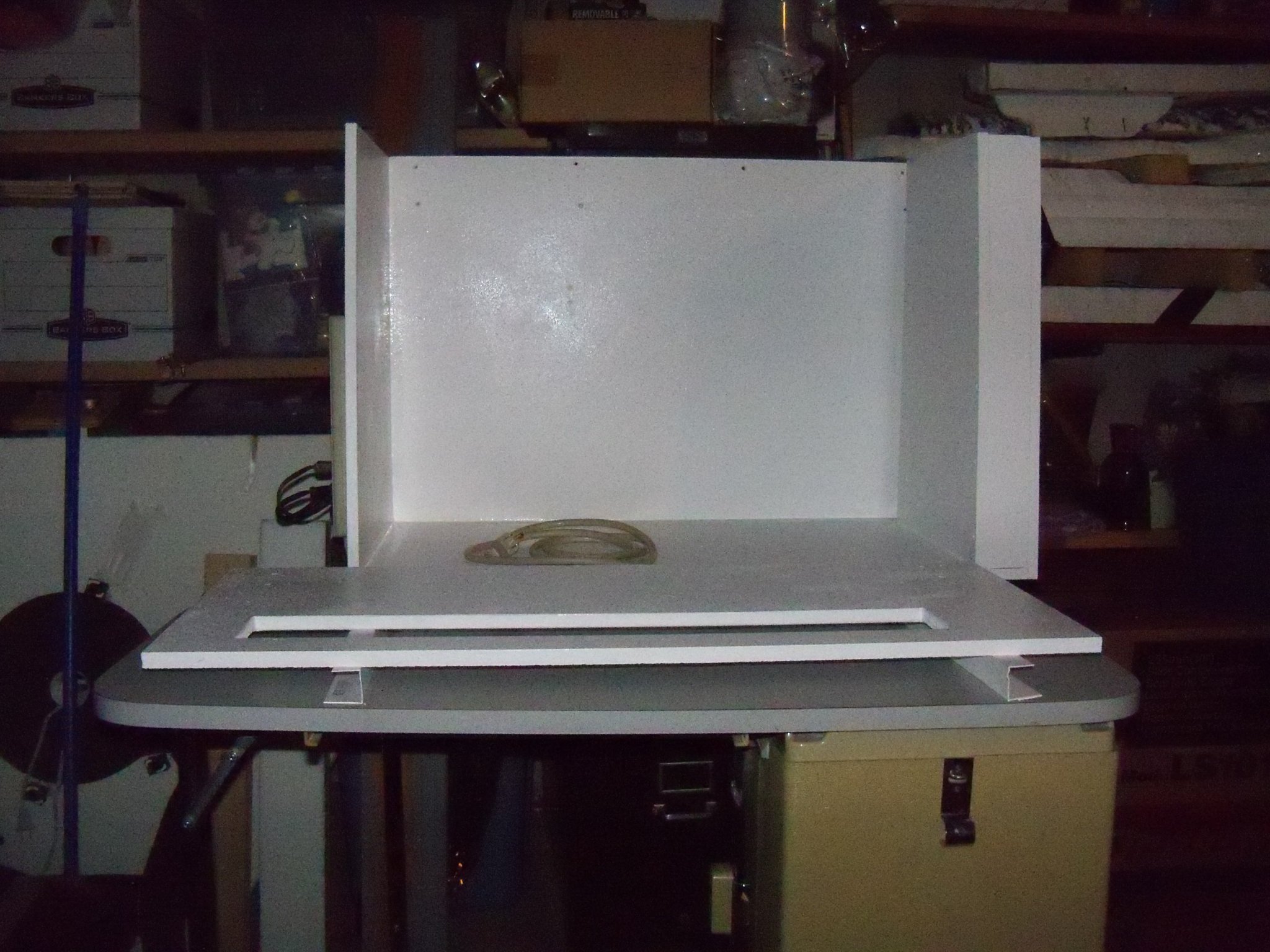
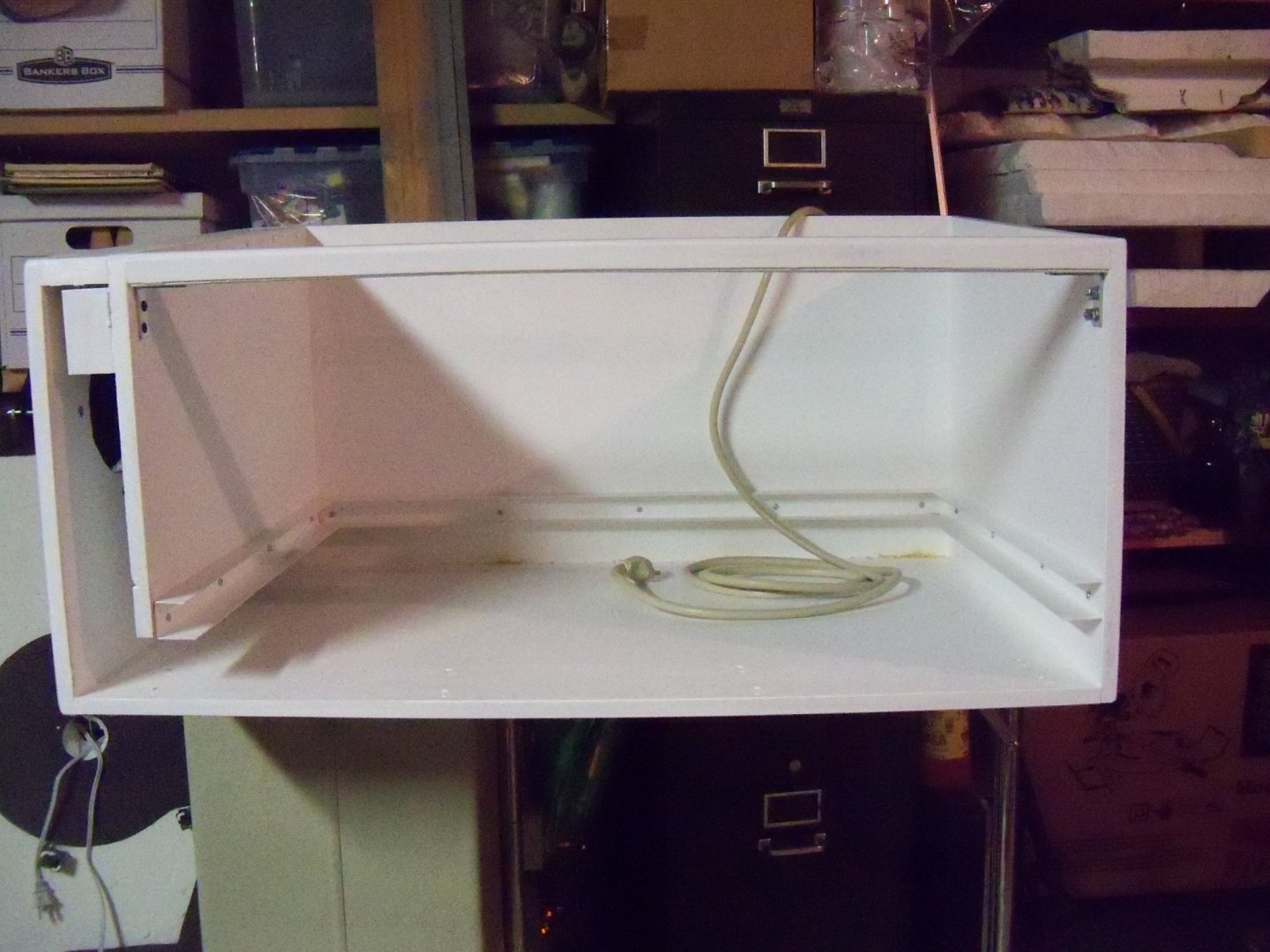
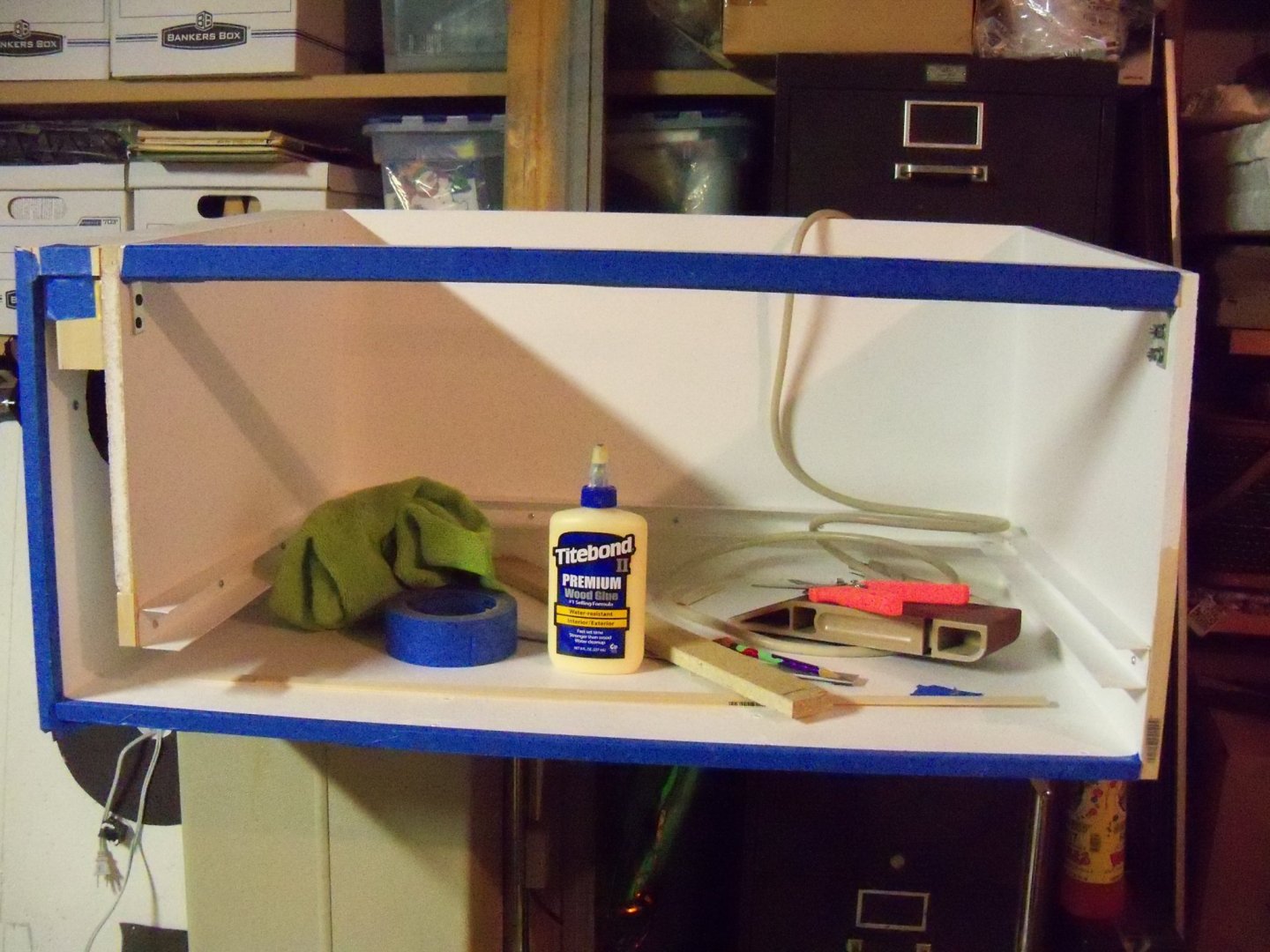
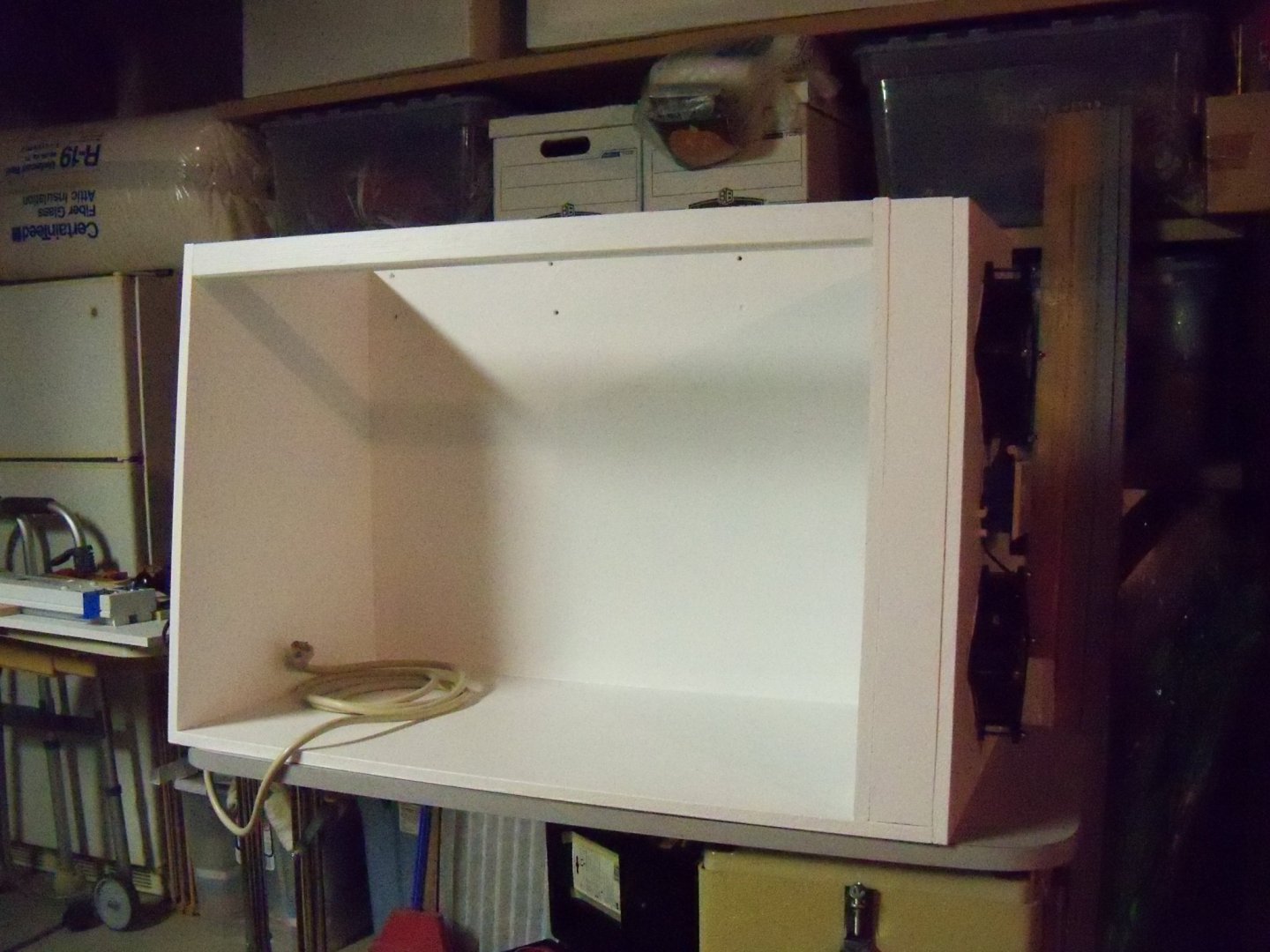
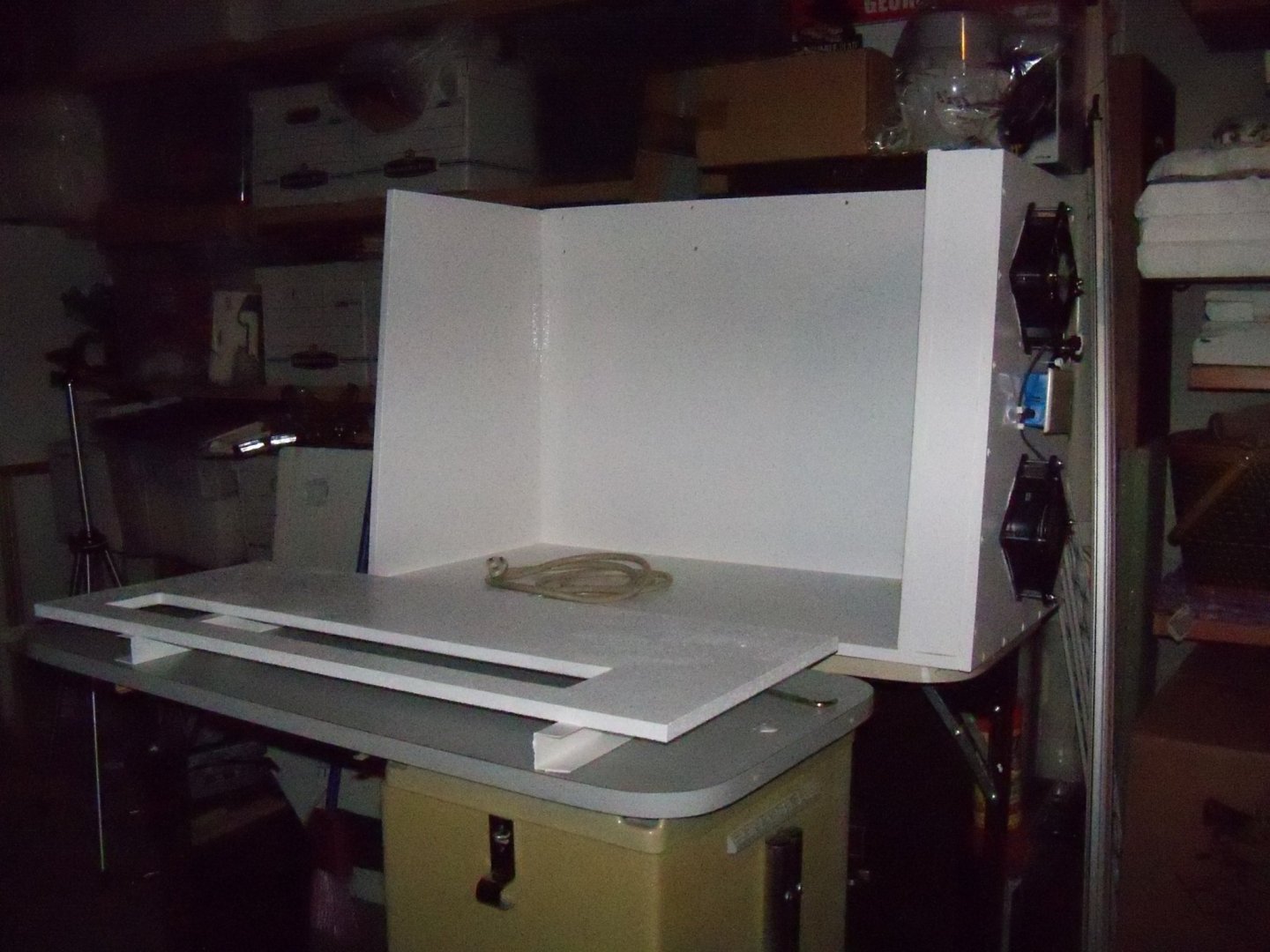
Not much accomplished today, but I managed to get the brace painted and attached. Not sure how much I will be able to do on the booth for a bit, as I need to get started on preparing for the holidays which includes the Xmas displays. Here is the current status of the project.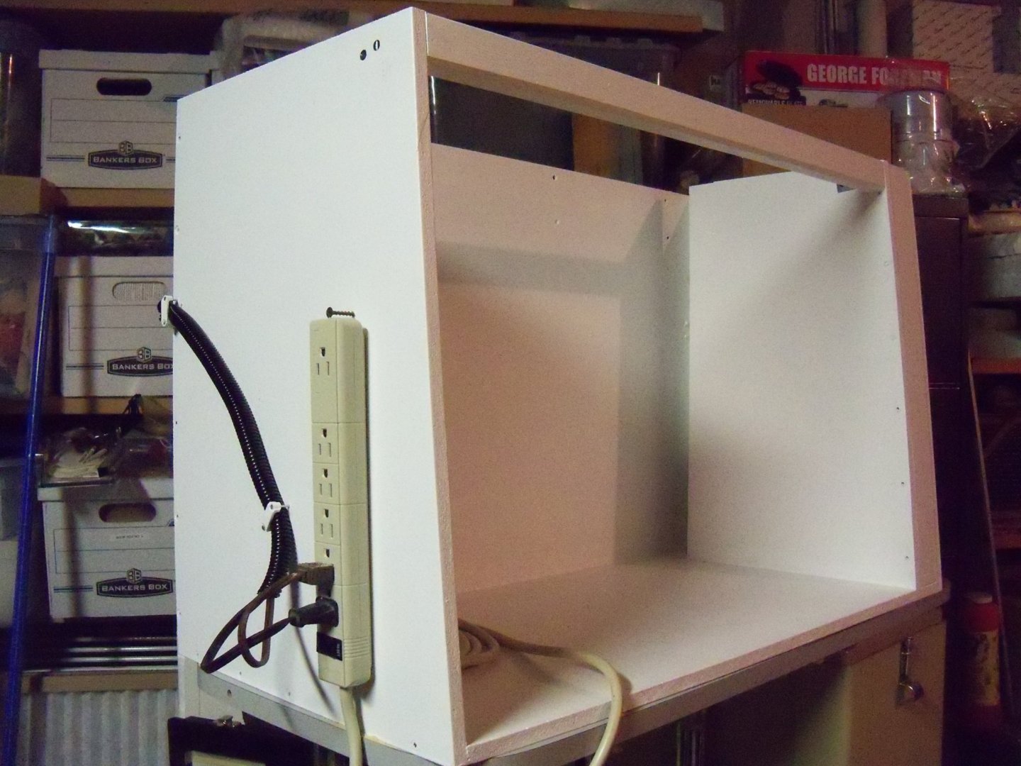
-
Hektor, if that Santa Maria you have is the 1/118 scale version, then yes I would also recommend that ship. Those smaller scale ships would be more difficult to work with, especially when you have to reach through the rest of the rigging to run another line or to tie one off. That’s something that you didn’t have to deal with on the airplane models you’re used to. Generally speaking, with the larger scale ship models like the 1/96 Cutty Sark, it’s easier to handle the larger parts, but the overall model is much more complex to tackle as a first try. Take it from me as I’ve built it a long time ago and had to take several breaks in the construction due to the frustration of handling that complexity! Bye the way, although I’ve never been to Sweden myself, both my grandfather and grandmother were born and raised about 2 ½ miles NE of Stromstad or about 250 miles NW of Ystad. Welcome to MSW from a half Swede.
-
Homemade Spray Booth
BETAQDAVE replied to BETAQDAVE's topic in Modeling tools and Workshop Equipment
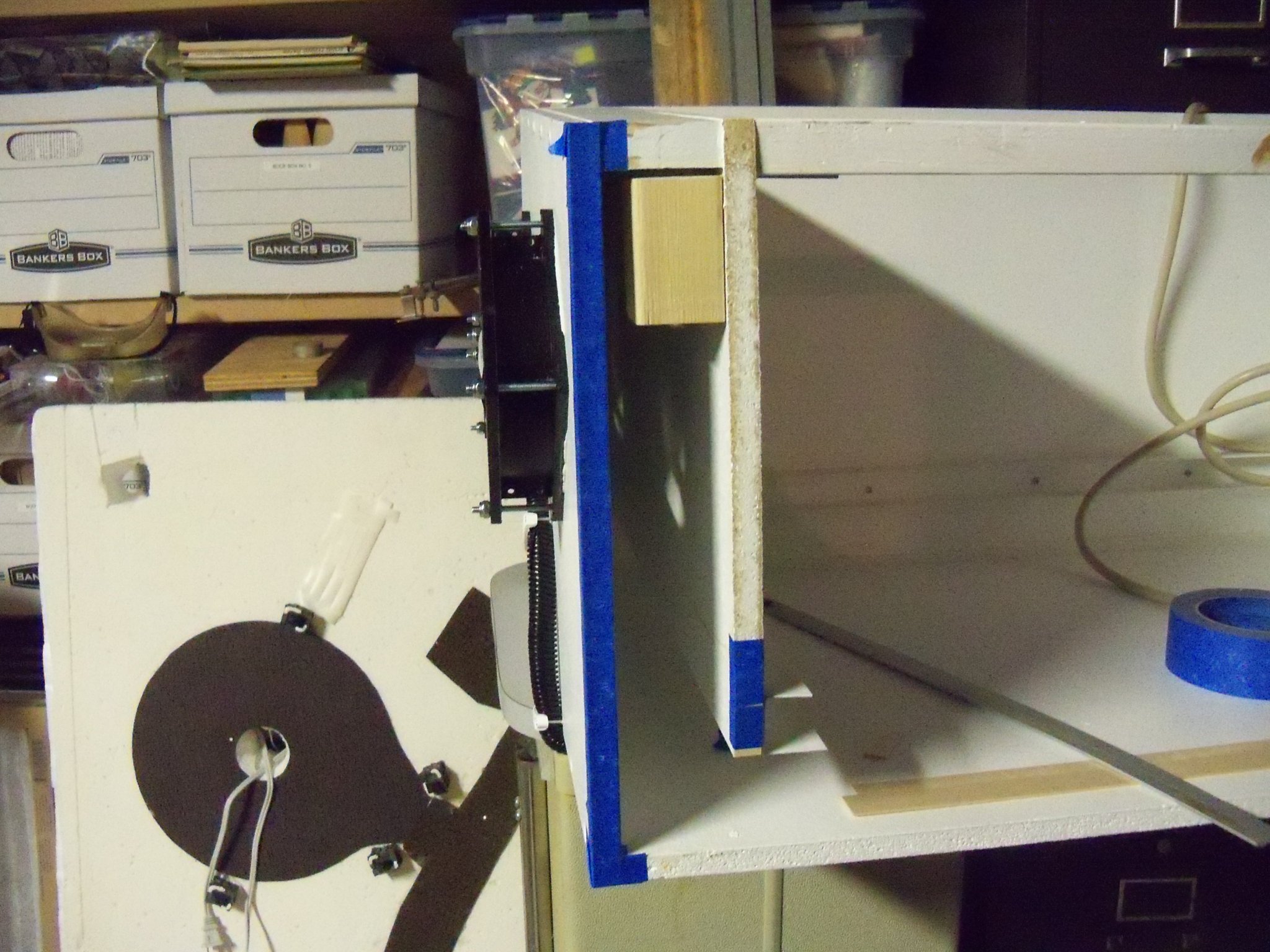
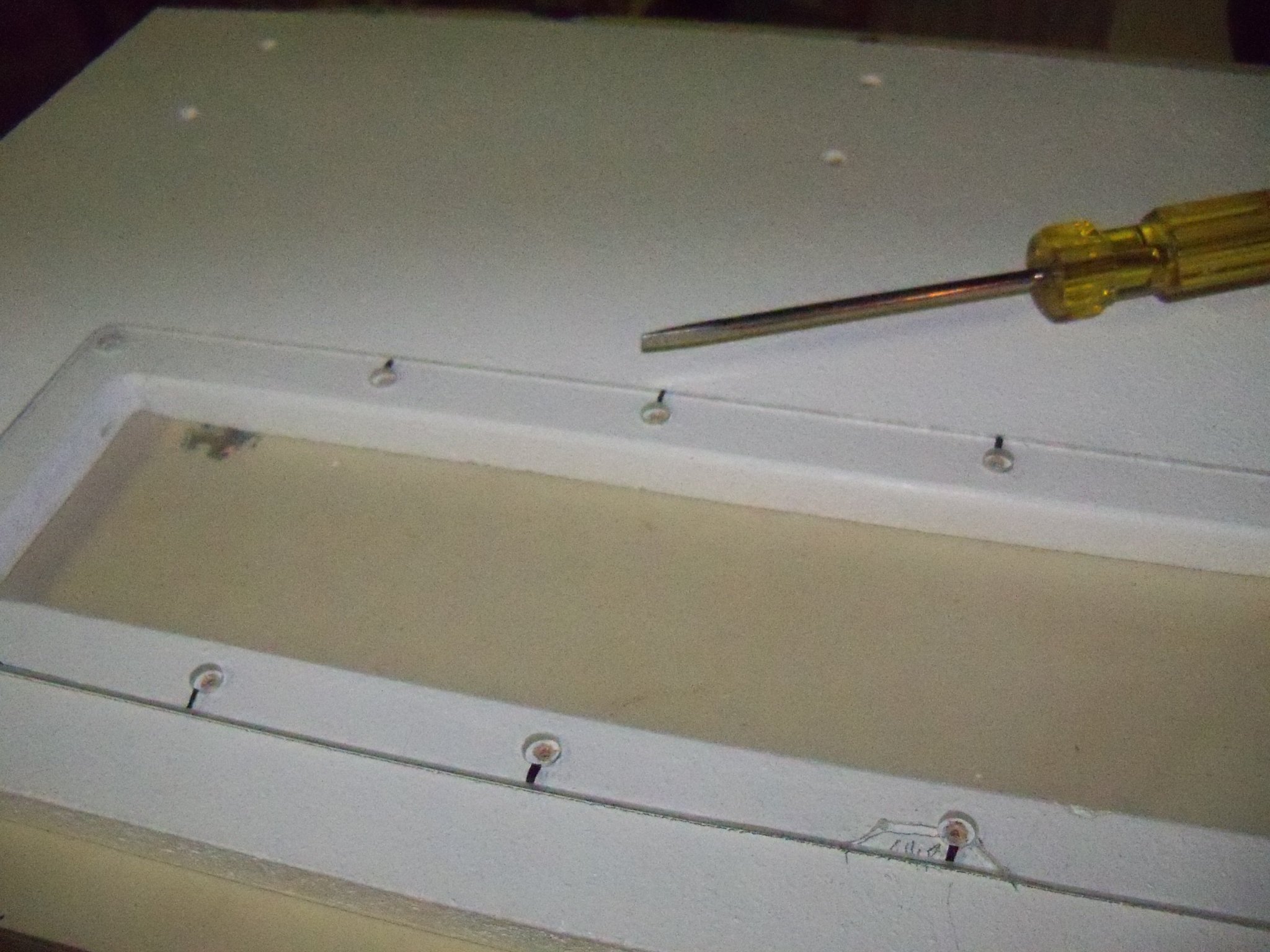
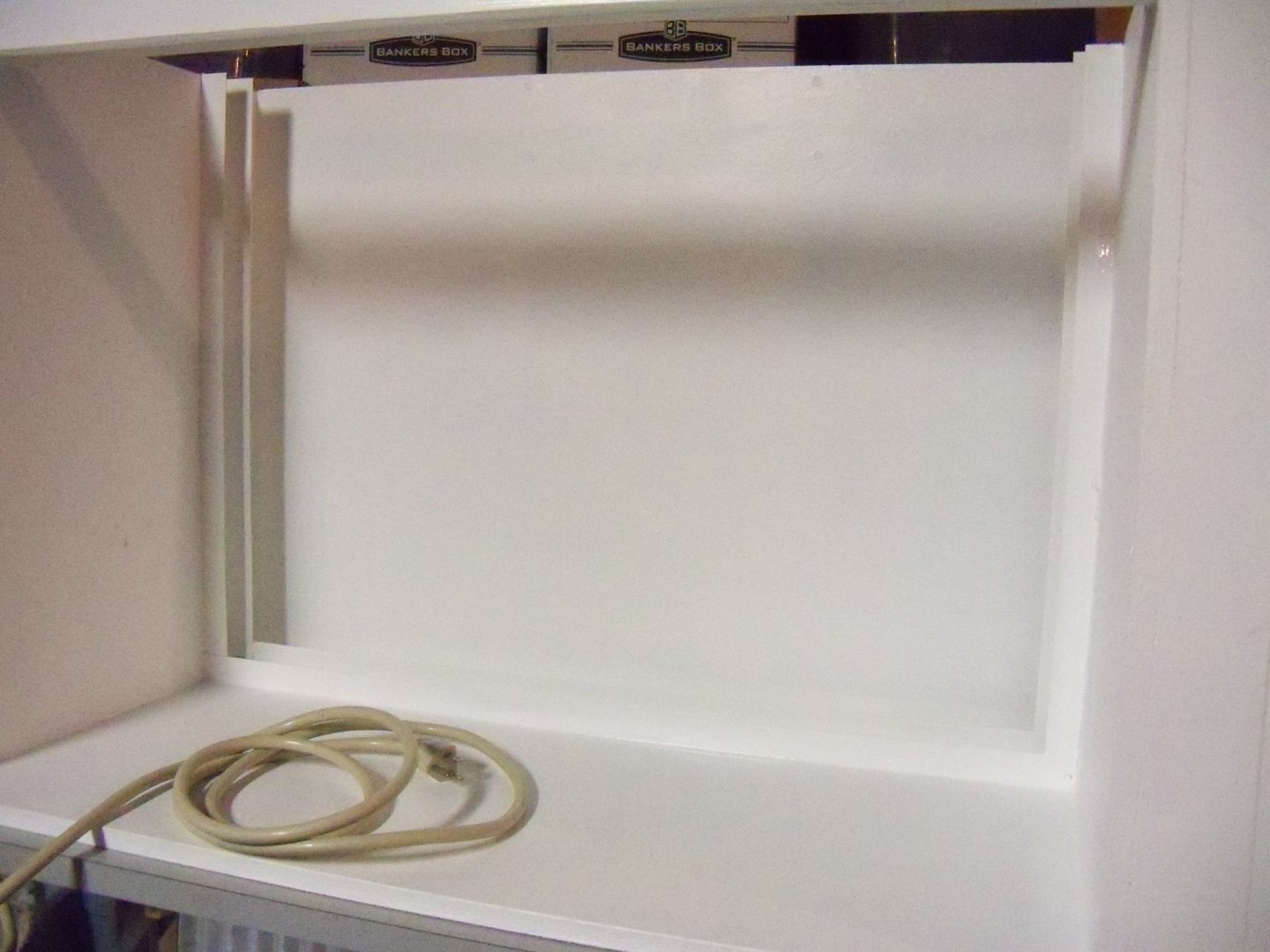
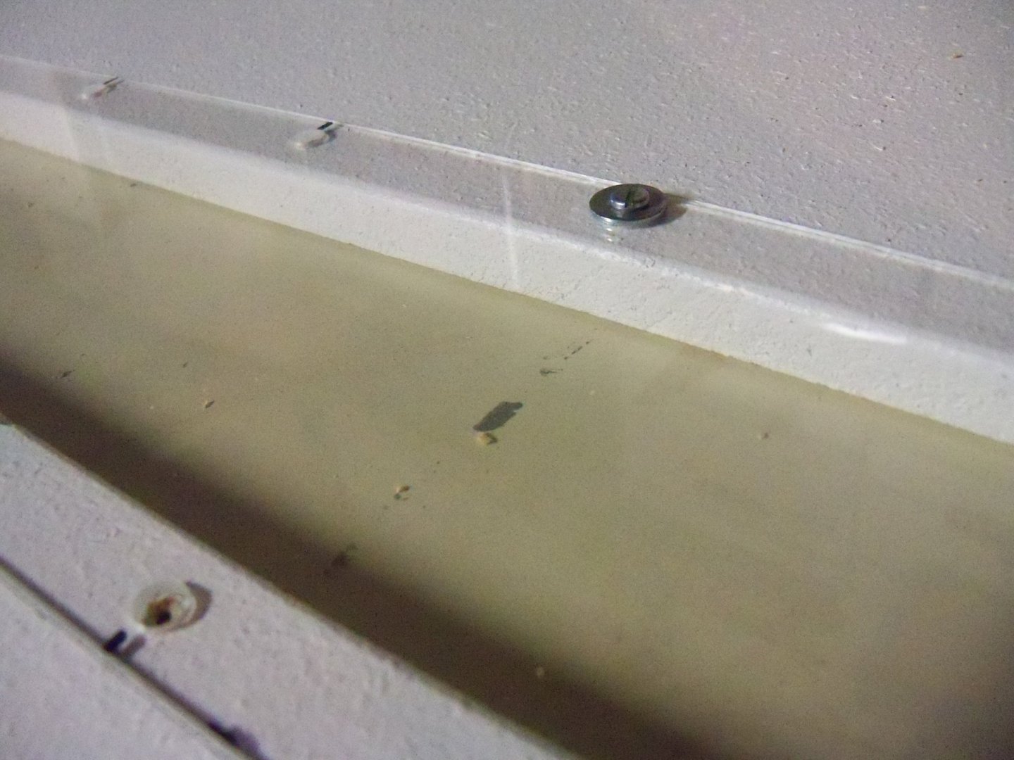
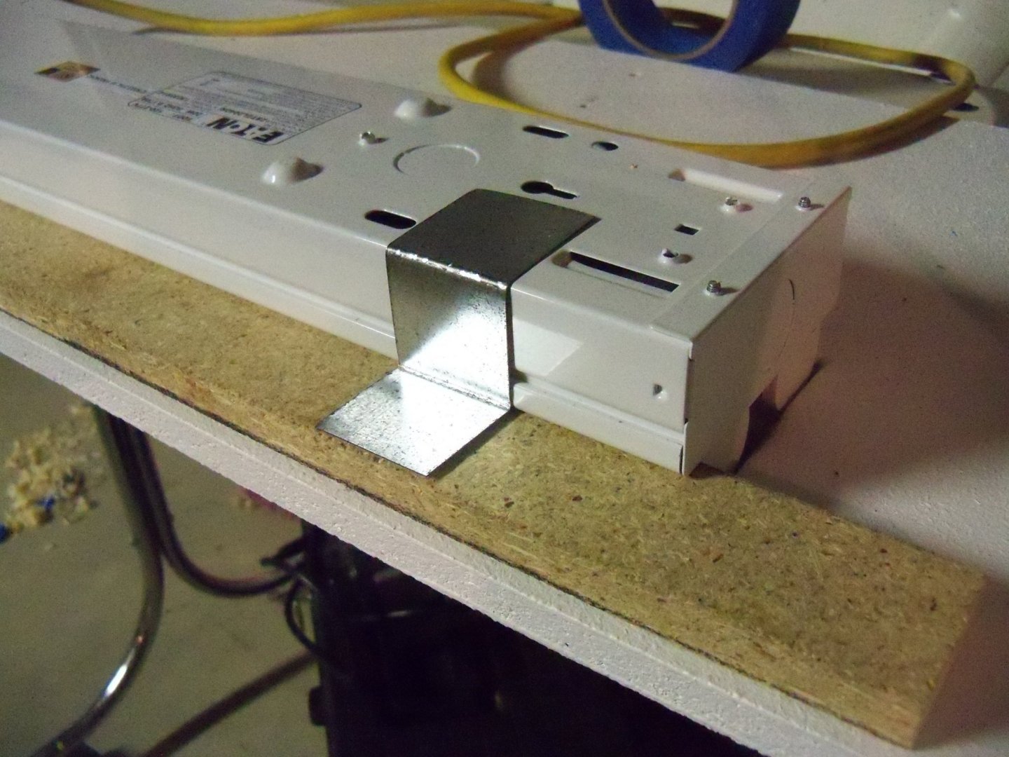
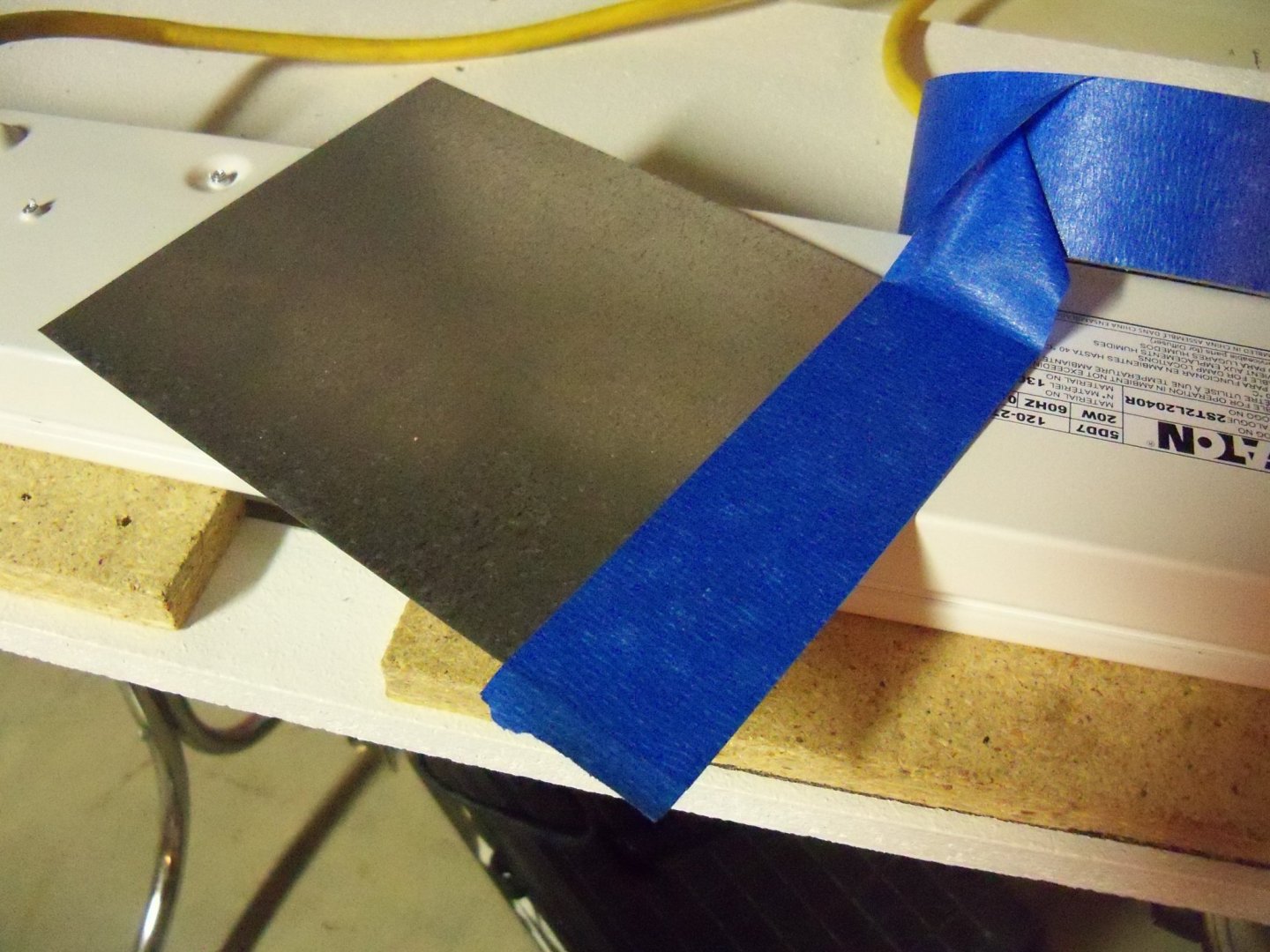
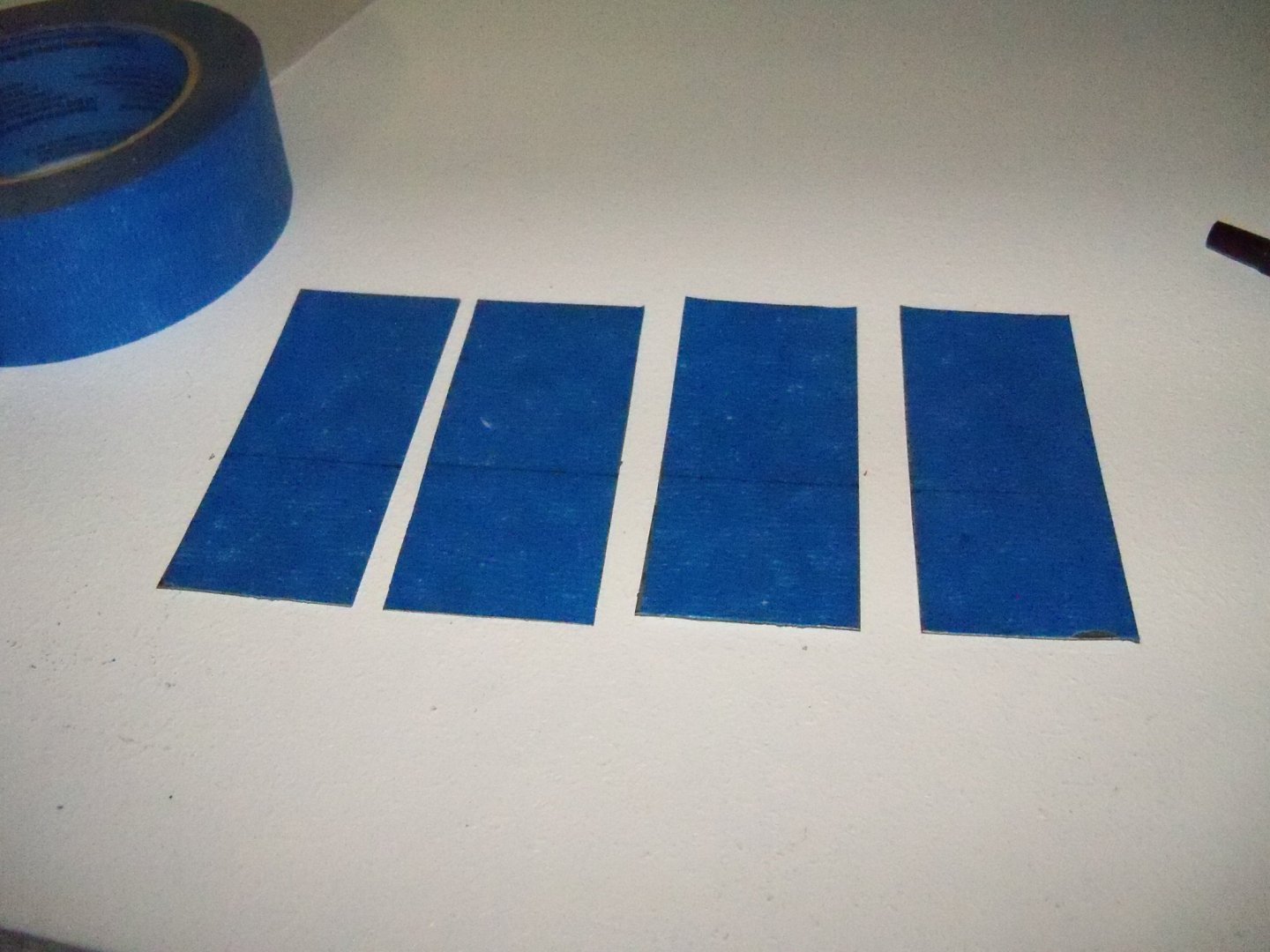
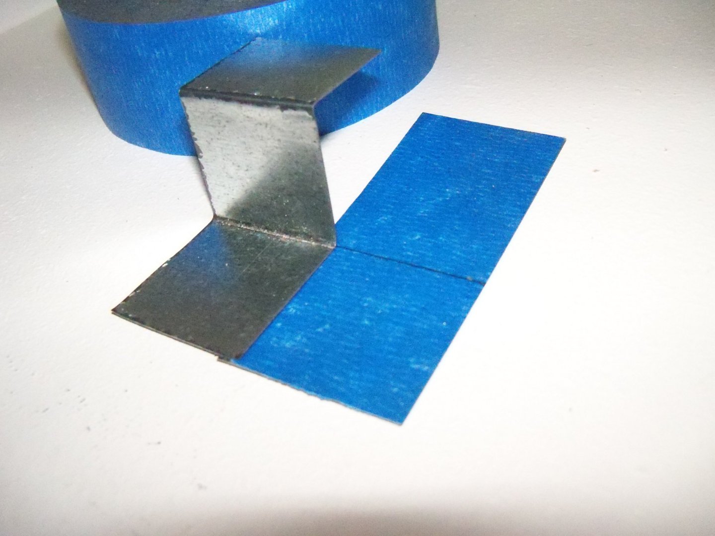
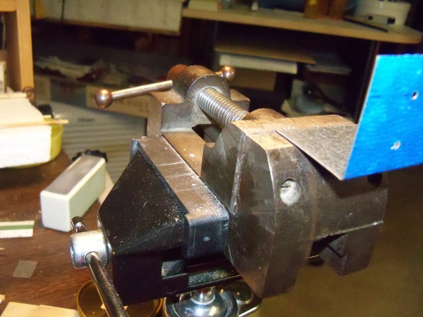
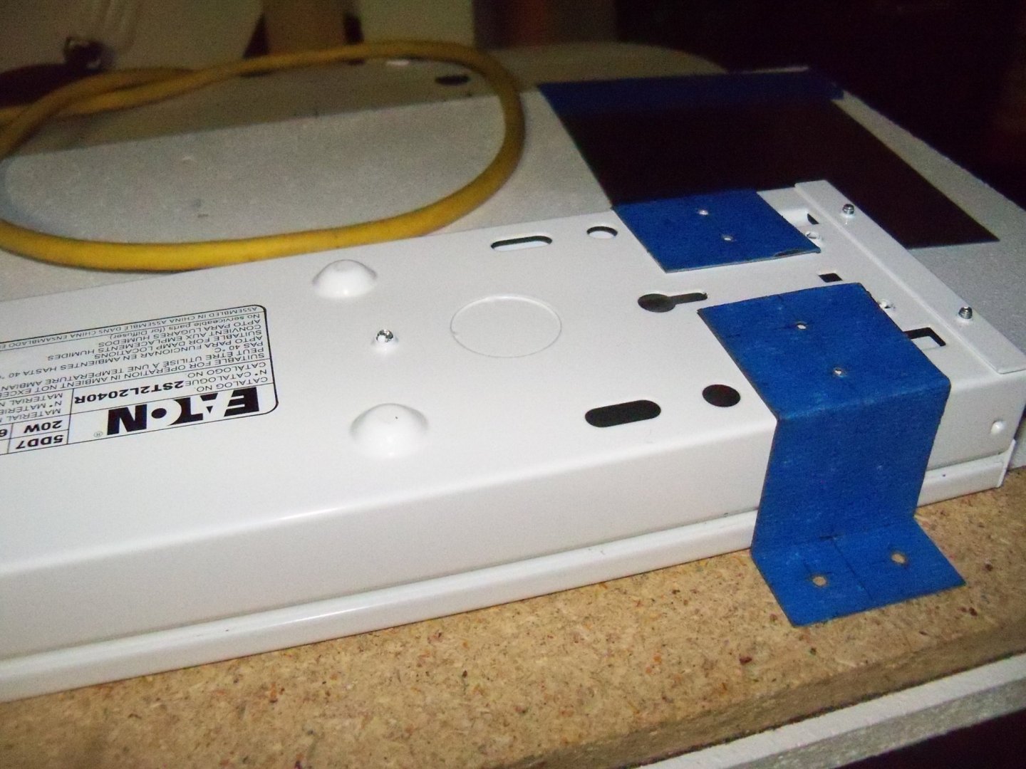
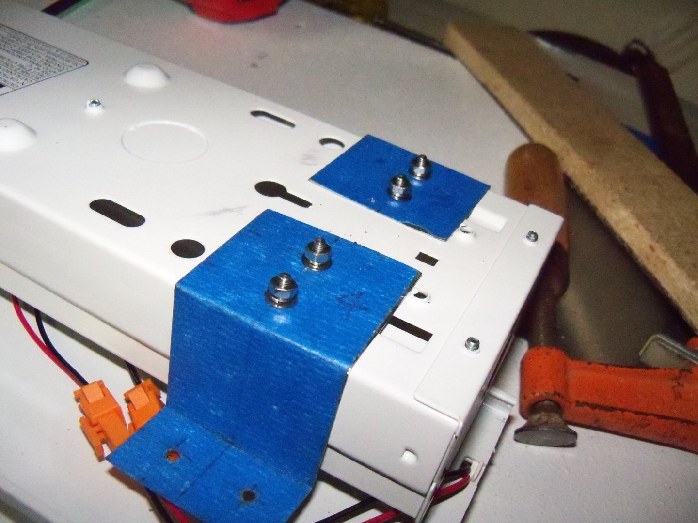
I positioned the Plexiglas over the opening on the bottom side of the top panel and traced around it to make it easy to re-position when removing it to install the tear-offs. Using a center punch, all of the screw holes were located in the exact center of the Plexiglas holes so it would be able to expand and contract once it was screwed down. The Plexiglas was set aside and I used a 5/64” bit to pre-drill the pilot holes for the screws. (I purposely drilled them well under sized to allow the screws to get a tighter grip in the particle board.) Once all the holes were drilled, the Plexiglas was re-positioned and all 18 of the ½” long 9/64” pan head wood screws were installed with flat washers. By flipping the top panel over and setting the light fixture into the opening you can see that the light fixture housing sits almost ½” proud of the particle board. Since this would allow light to leak out where it’s not wanted, strips of ½” particle board will be added to fill this gap and serve as a raised mounting board for the brackets. (It will also stiffen the front edge of the top panel.) I fashioned a prototype of the bracket from a piece of galvanized tin shingle into this 1 ½” wide Z shape to mount the light on this raised mounting board. Using the remainder of the shingle, I fashioned the four light mounting brackets. I applied some 1 ½” wide painters tape on the shingle for each bracket so all of the brackets would be a consistent size and would make the cut line easy to follow. The locations of the two bends from the prototype were then marked on each piece and one leg was shortened for use on the raised mounting board. The pieces were the marked for the mounting screw holes. Each long flange was drilled with a 1/8” bit for two Philips head bolts for attaching to the fixture. Each of the short flanges was then drilled with a 9/64” bit for a pair of wood screws for attaching it to the raised mounting board. Using my machinists vice, the flanges were bent over on the marks previously drawn on the tape. Unfortunately I don’t have a bending break, but the tin was thin and bent readily. I placed the brackets where the bolts wouldn’t interfere with anything inside the fixture. The fixture was opened up and the brackets were clamped to the fixture so I could use them as drilling guides for the bolts. I drilled eight 1/8” holes and the 3/8” long 7/64” bolts were then installed from the inside out, with a flat washer, a lock washer and hex nut on the outside for each. Despite my efforts to keep the particle board straight and flat, I discovered that when the top panel was test fit, the panel was no longer covering the entire width of the front opening. Measuring the overall width of the booth at the bottom was 31 11/16”. However the same measurement at the top was now a full 32”! Checking the upper corner of the left side panel closer, it was found to have warped. Taking out a bar clamp, I tightened it until the top and bottom measurements were equal. The only easy solution seemed to be adding a wood brace across the opening at the top. I found a scrap of 5/4 clear pine that was long enough to fit and I trimmed it down to 1 1/2'’ wide on my band saw. It was a rather rough cut, but a block plane, a scraper and a little elbow grease cleaned it up just fine. Measuring the space with the bar clamp still in place, it was cut to length and put in place. The fact that my booth is wider than the original probably contributed to the need for one. While the brace wasn’t a feature that I had planned on having it will certainly make it stronger and prevent the top panel from sagging. The brace, being as slim as it is, shouldn’t detract from the view-able area very much. I’ll just give it a coat or two of paint and anchor it in place with some small angle braces.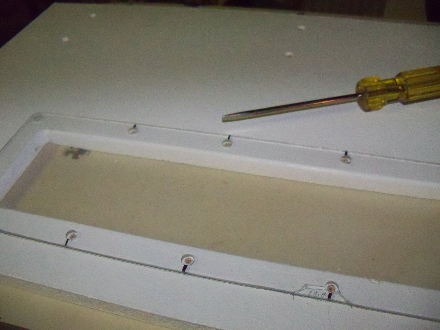

-
Pantograph to enlarge plans
BETAQDAVE replied to Sambini's topic in Modeling tools and Workshop Equipment
I have tried that once and was not satisfied with the results. Although to be honest, the pantograph that I used was made of wood and some more pricey metal units are available, you still need a sharp eye and a very steady hand with the stylus to follow the original lines. I found that I had to use a light touch with a 4H lead in the stylus so that I could later redraw and even out the lines with ships curves. All in all, going to a professional print shop will give you a much faster and more accurate result. Also, if the ship is small enough to fit your available paper size, you can even use your computers' printer if it has enlargement and reduction capabilities. -
Homemade Spray Booth
BETAQDAVE replied to BETAQDAVE's topic in Modeling tools and Workshop Equipment
Once the booth is in operation, the spray from the booth would cover the Plexiglas eventually so I decided to take Dons suggestion to use a trick used by dirt racers and motorcyclists referred to as: the tear-off. This is accomplished by using a piece of transparent packaging tape stretched over the Plexiglas light window with one end doubled back about ½” to form a pull tab. When the light cover gets too opaque from spray paint, you simply grab the pull tab and peal it off. You can put multiple layers of tape on the window to allow you to rip off the topmost layer one at a time. This allows you to repeat this operation several times before having to open up the booth to put on a new set of tear-offs. On Dons booth, he had a single bulb light whereas my booth has two, thus making my light window a bit wider. The tape only comes in a width of slightly less than two inches, but I will simply overlap two pieces of tape for each tear-off. Applying these strips is much easier to do when the Plexiglas is removed from the top panel and laid out on a flat surface, so to avoid doing that too often; I plan on making four tear-off strips for mine. My next step will be to position the Plexiglas window on the inside face of the top panel and predrill some holes for the mounting screws. Then I will proceed to make some mounting brackets for the light fixture. -
Homemade Spray Booth
BETAQDAVE replied to BETAQDAVE's topic in Modeling tools and Workshop Equipment
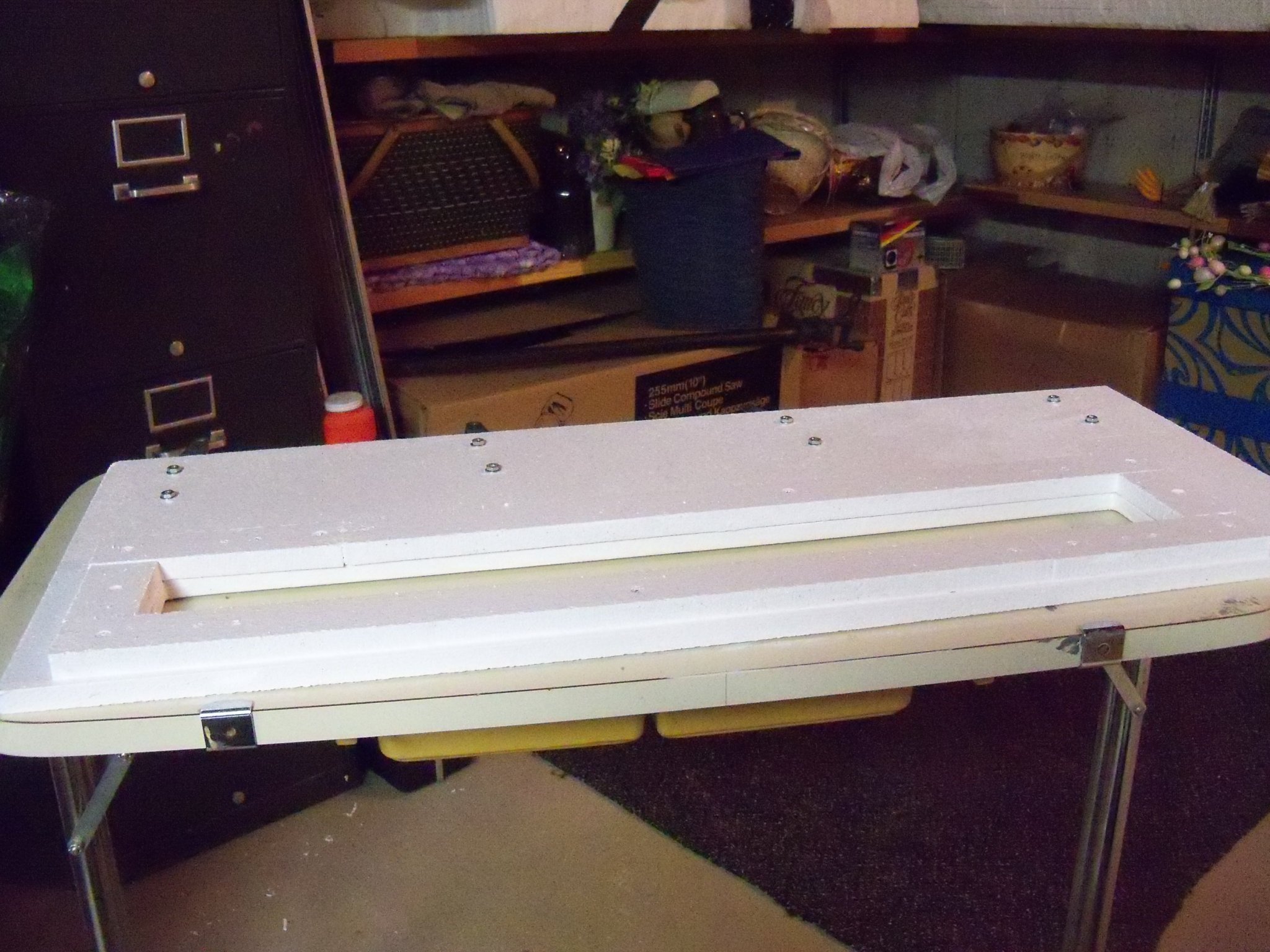
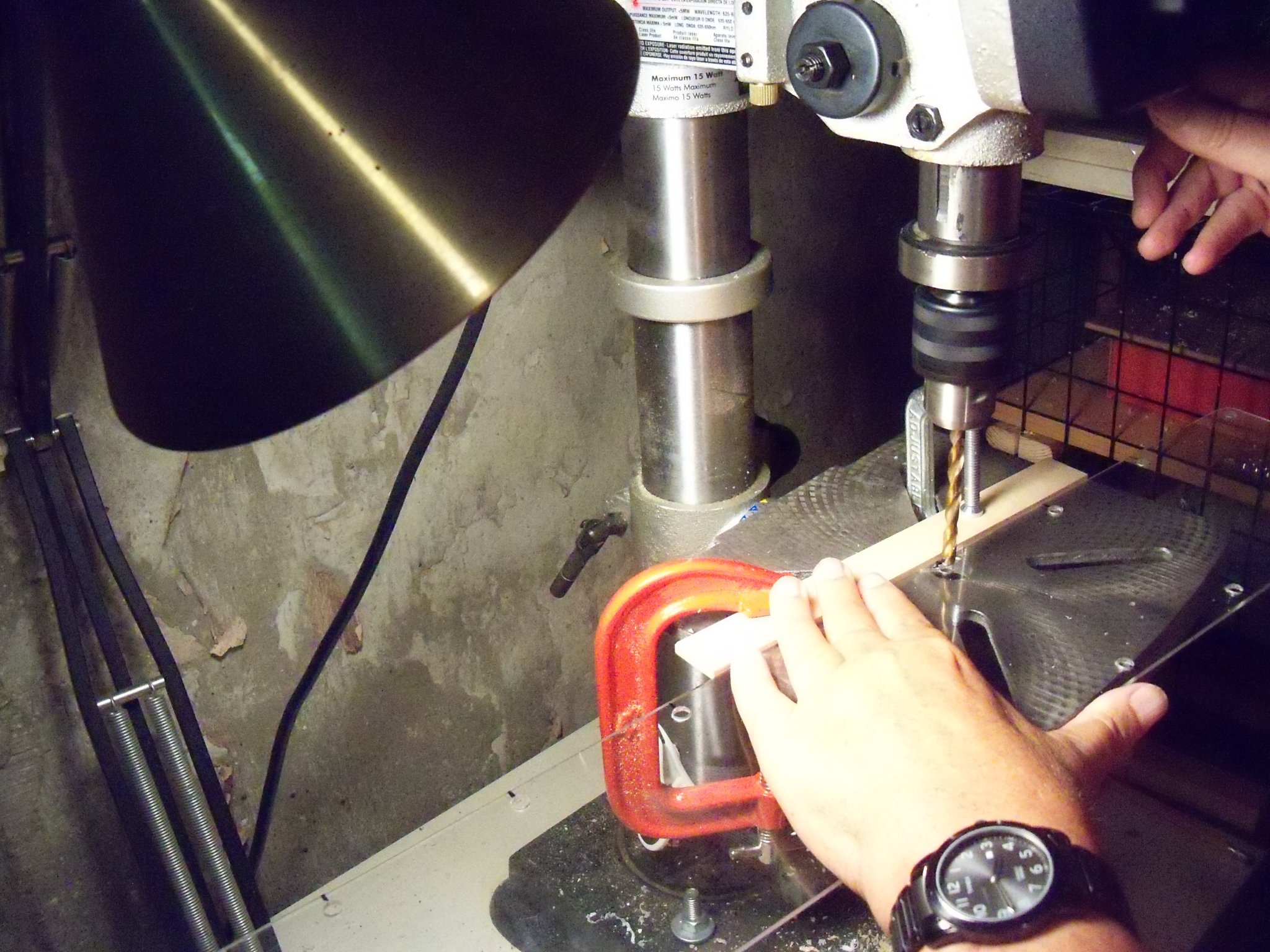
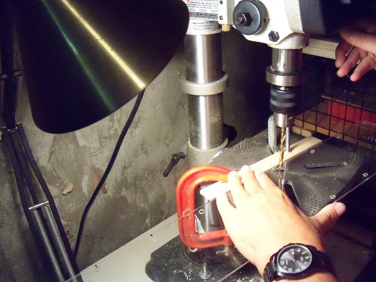
I gave the edges and top surface of the top panel three coats of paint yesterday after removing the hinges. A final coat was also given to the inside of the booth and a bit of touch up to every hole that was drilled. I think that it should be pretty well sealed to protect it now from humidity changes. I set up my drill press with a guide fence to locate 18 evenly spaced holes 3/8” from the edge of the Plexiglas panel. I will be using some ½” long 9/64” pan head wood screws with flat washers to attach it to the inside face of the top panel. The holes were drilled oversize with a 3/16” bit to allow for any movement between the particle board and the Plexiglas. Things went along smoothly until I got to the last hole (of course), when the bit caused the Plexiglas to fracture and break off a large chip from the edge. Apparently I must have used a little too much pressure with the drill. Luckily it was in one piece and I just glued it back onto the edge with plastic cement and set aside to cure so I could finish drilling the hole later. The repair to the Plexiglas worked just fine and I finished drilling the holes today. I decided to increase the size of the holes to ¼” to allow a little more room for expansion and contraction. My guide fence on the drill press was still in place, so it was an easy adjustment. (I was very careful drilling them this time however.) Here is the current status of the booth.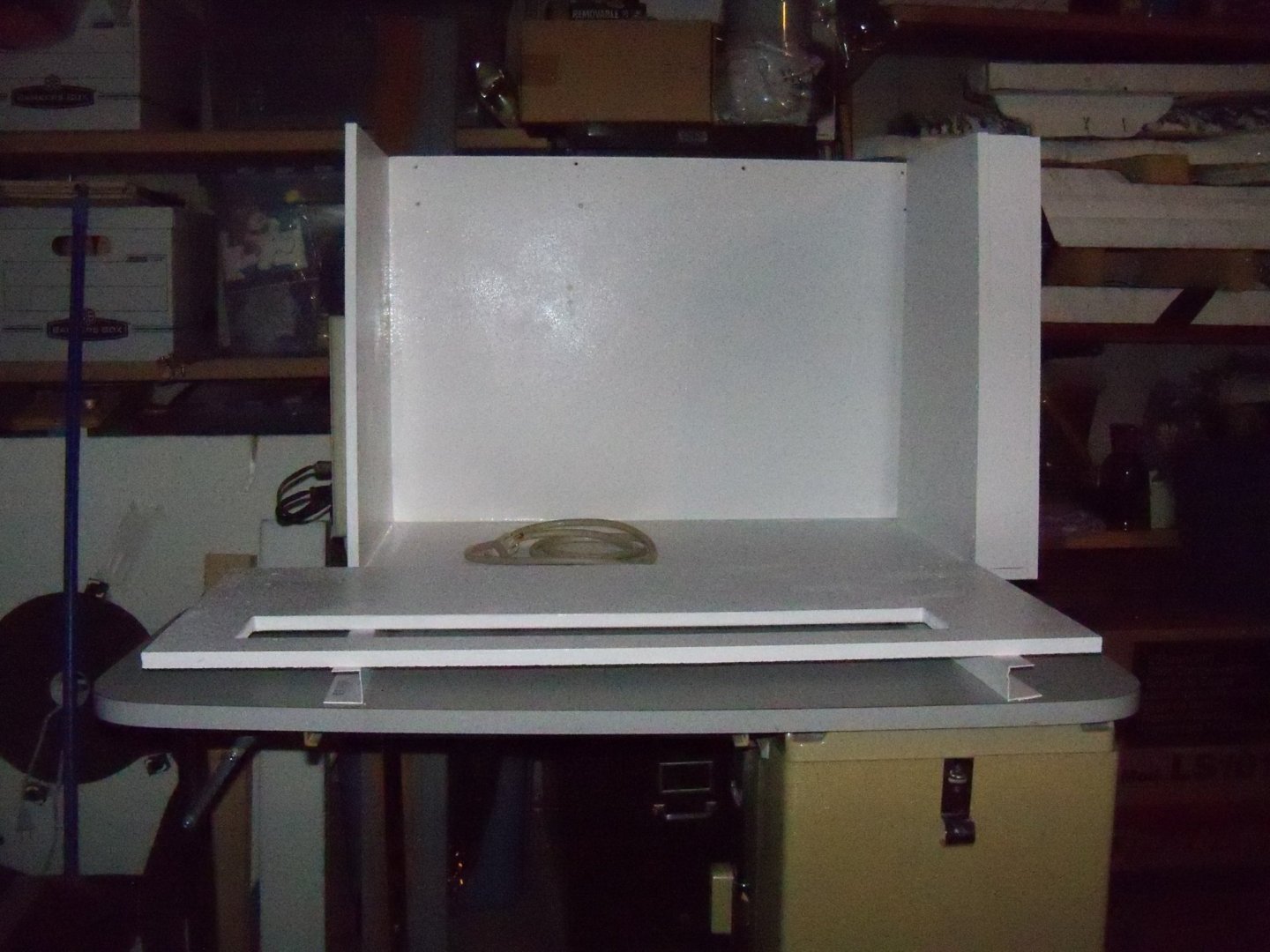
-
Homemade Spray Booth
BETAQDAVE replied to BETAQDAVE's topic in Modeling tools and Workshop Equipment
I managed to start on the top panel by cutting out the opening for the light fixture. Holes were drilled in the corners for using my saber saw, and I did use it to cut about two feet. But, I noticed that the saw wasn’t following my line even though a guide was clamped to make it do so. Upon closer inspection, I found that the blade was bending off to one side. I assumed that is was due to the blades alignment being out of whack. Since the procedure to get it realigned was rather tedious, I decided to just use a short bladed hand saw to complete the cut by twisting the blade a bit to force it back in line. I still used the saber saw to make the short cuts on the end and make a kerf enabling me to use my hand saw to complete the cut, but I guided it along the line by hand without the guide. It turned out that I was able to cut faster and straighter with the hand saw anyway. Still, the cuts were a little ragged and needed to be evened out with rasp and sandpaper. The back side of the cuts was especially rough, so I just eased the edges a bit. I took out a sheet of 1/8” thick Plexiglas and laid it over the cut–out to size it with about ¾” overlap. Using a felt pen the size was marked and it was set aside to cut later. Now I marked the location of the hinges evenly on the top side of the panel and numbered both the location and the hinges, as the hinge hole locations varied a bit. The hinges were then set one at a time on the panel with one leaf hanging over the edge and I used them as a template to locate the holes for the stove bolts. Those holes were then countersunk on the inside face of the panel to reduce interference with the air flow. The hinges were then temporarily attached to make it easier to locate the hinge holes on the back panel. Since my foam weather-strip was incorrectly shipped as ½” wide by ¼” thick rather than the 3/8” thick that I ordered, I needed to reduce the gap between the top and back panel. Luckily the hinge holes had not been drilled yet so I just used 1/8” spacers rather than the 3/16” that I planned on using. The weather-striping would thus be compressed when the top was closed to provide a tighter air seal. Returning to the Plexiglas panel for the light fixture, I decided to use my band saw to make the cuts to reduce the tear out on the backside of the cut. Once the panel was cut out, I used a sandpaper block to finish the edges and round over the corners. Tomorrow, I plan to continue working on the top panel.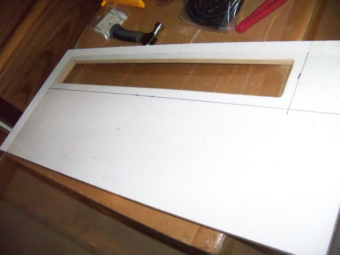

-
Allan, that is a finely detailed job there.
-
Dust port - hoover connector
BETAQDAVE replied to Matrim's topic in Modeling tools and Workshop Equipment
For a simple and inexpensive solution to this problem that will work with any size or shape of connection, try this. It consists of two scrap pieces of softwood with a hole for the hose in one piece and another piece with a hole sized for the tool. Once cut, you simply glue them together as shown. Now all you need to do is slip the fitting over the tool port and then insert your hose into the other.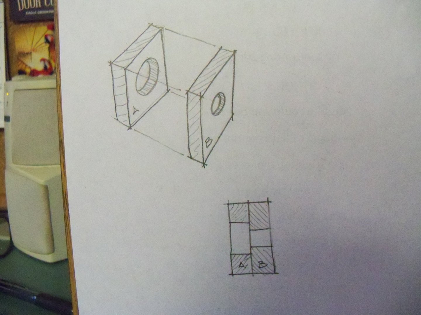
-
Homemade Spray Booth
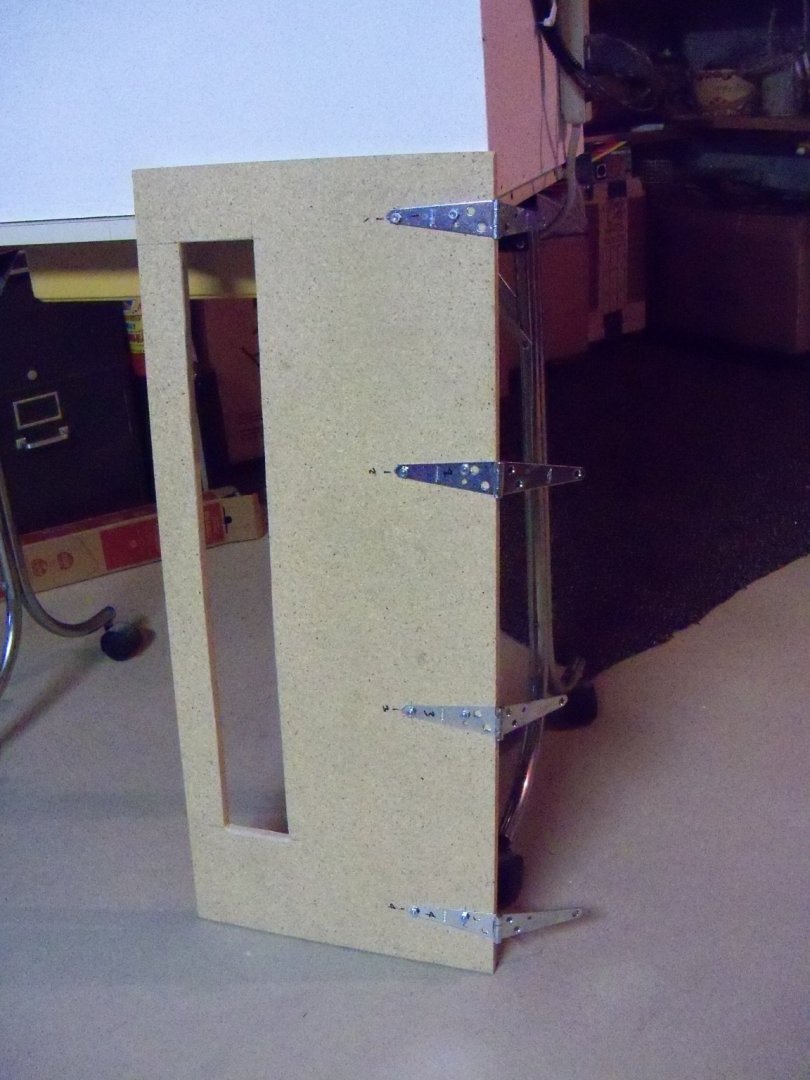
BETAQDAVE replied to BETAQDAVE's topic in Modeling tools and Workshop Equipment
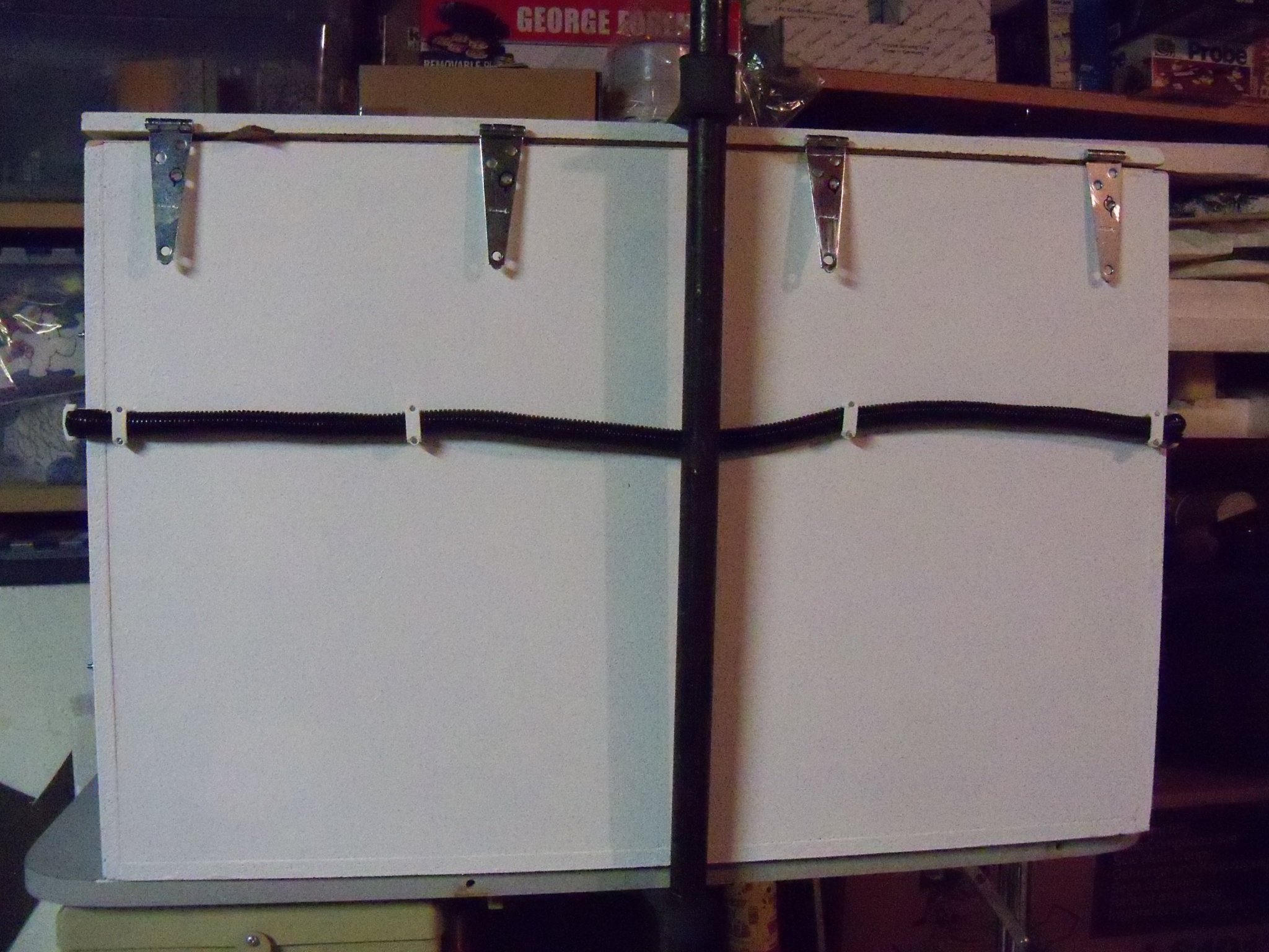
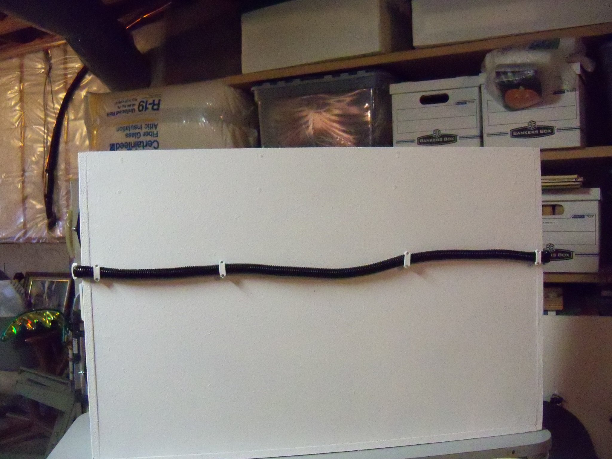
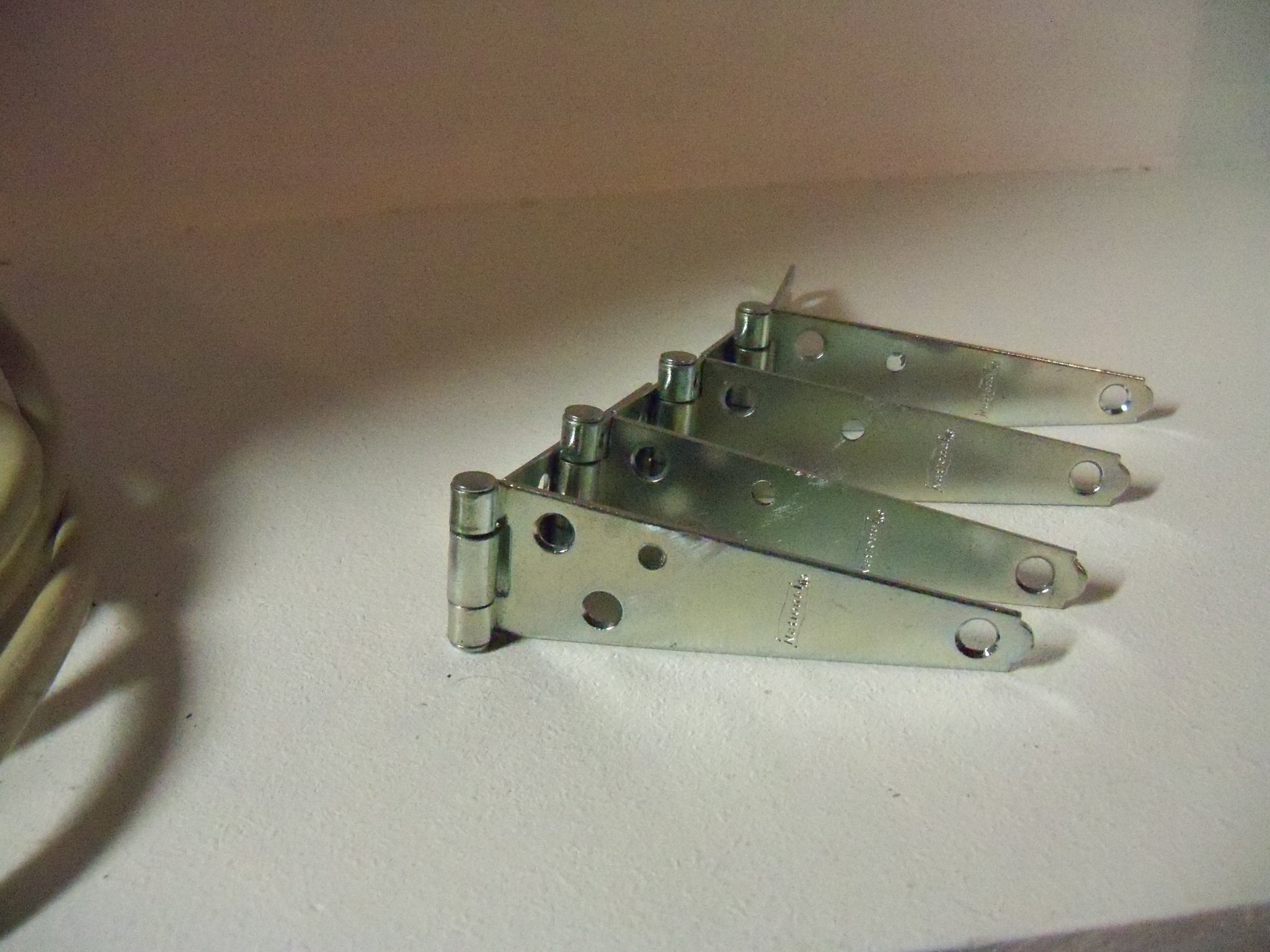
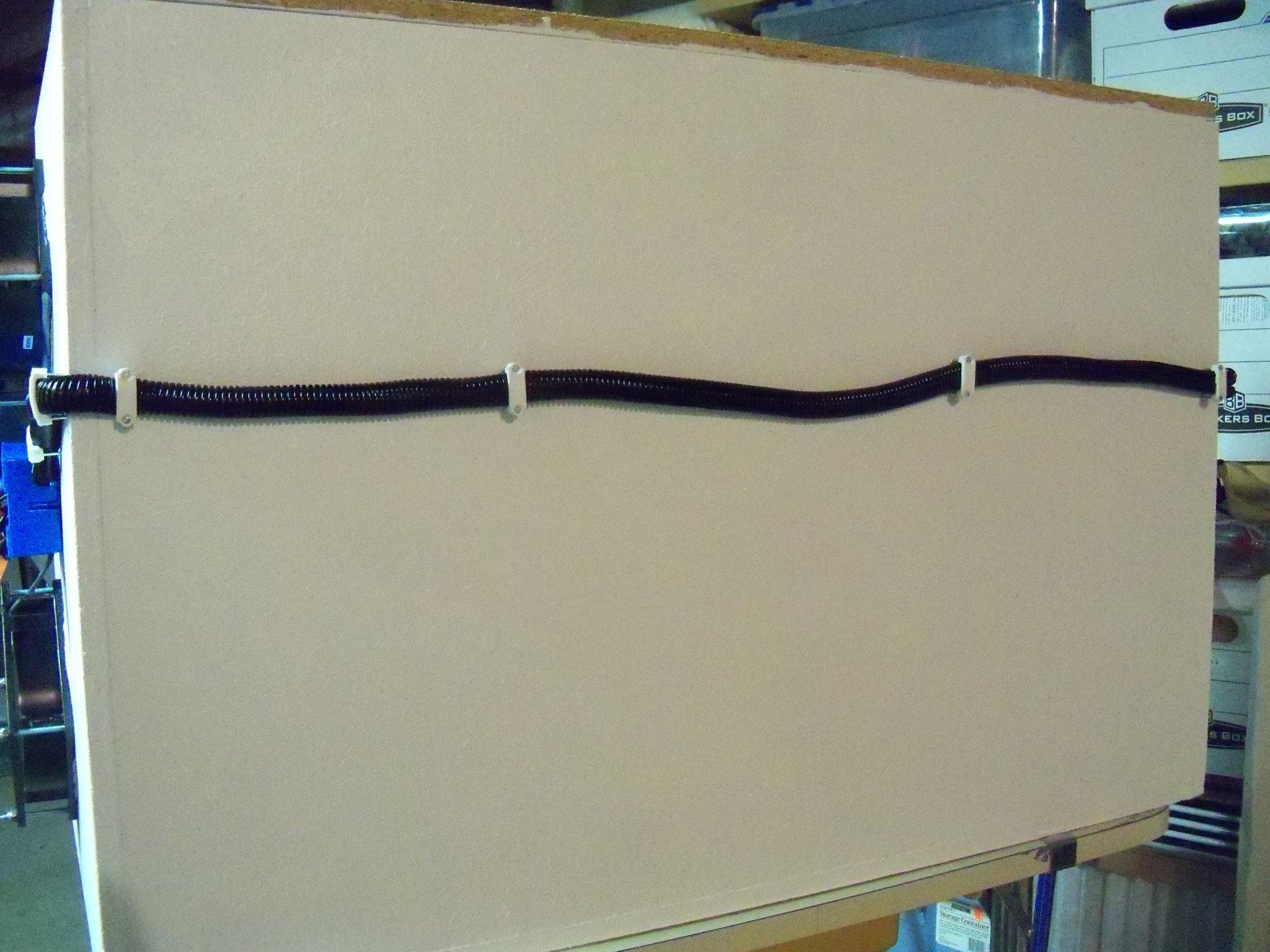
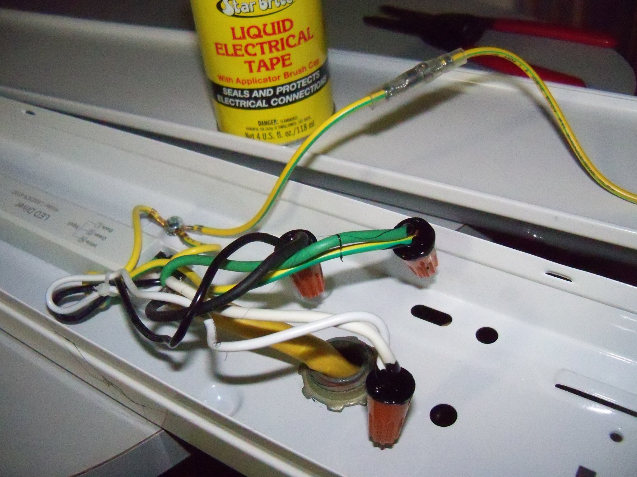
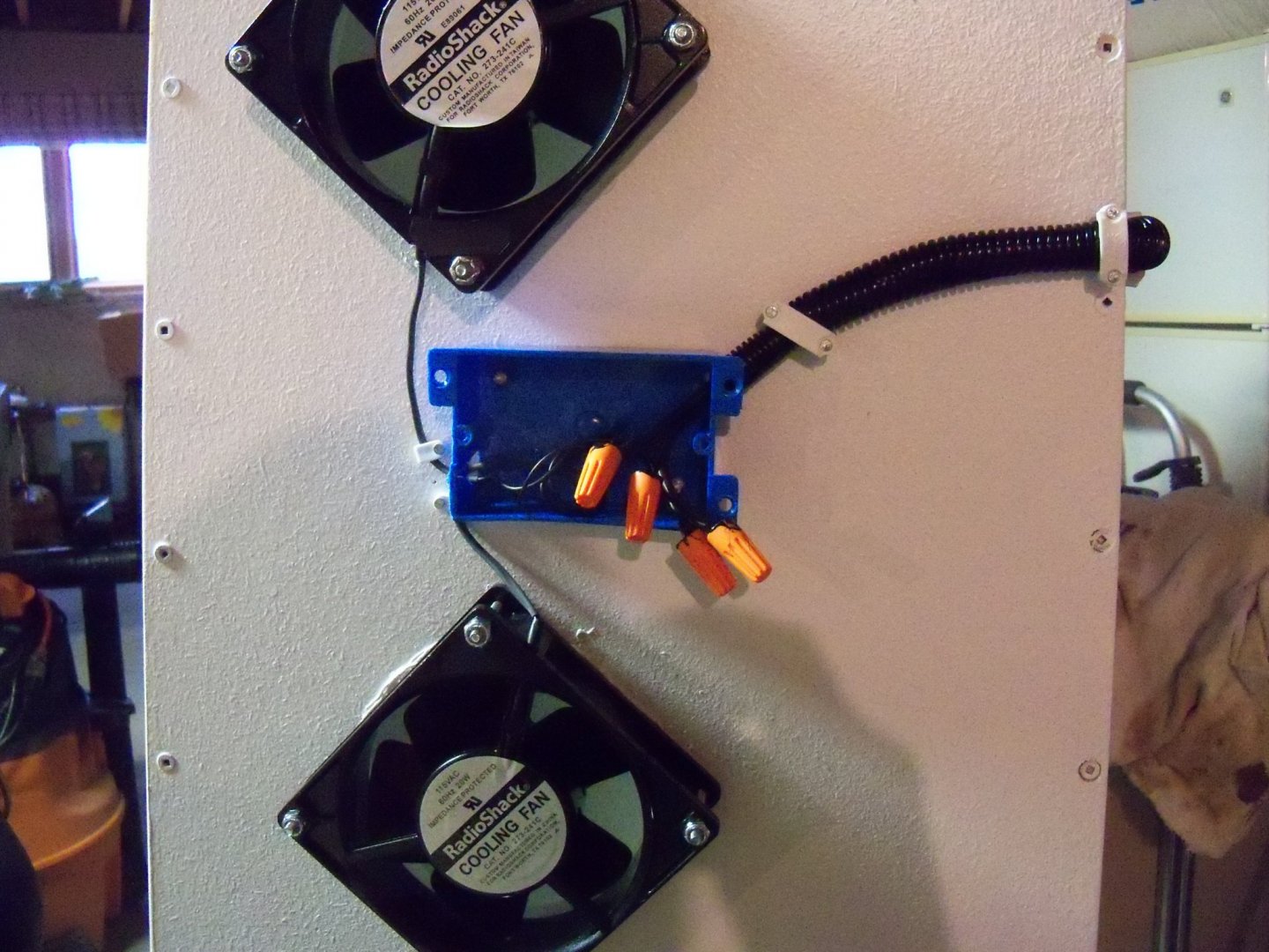
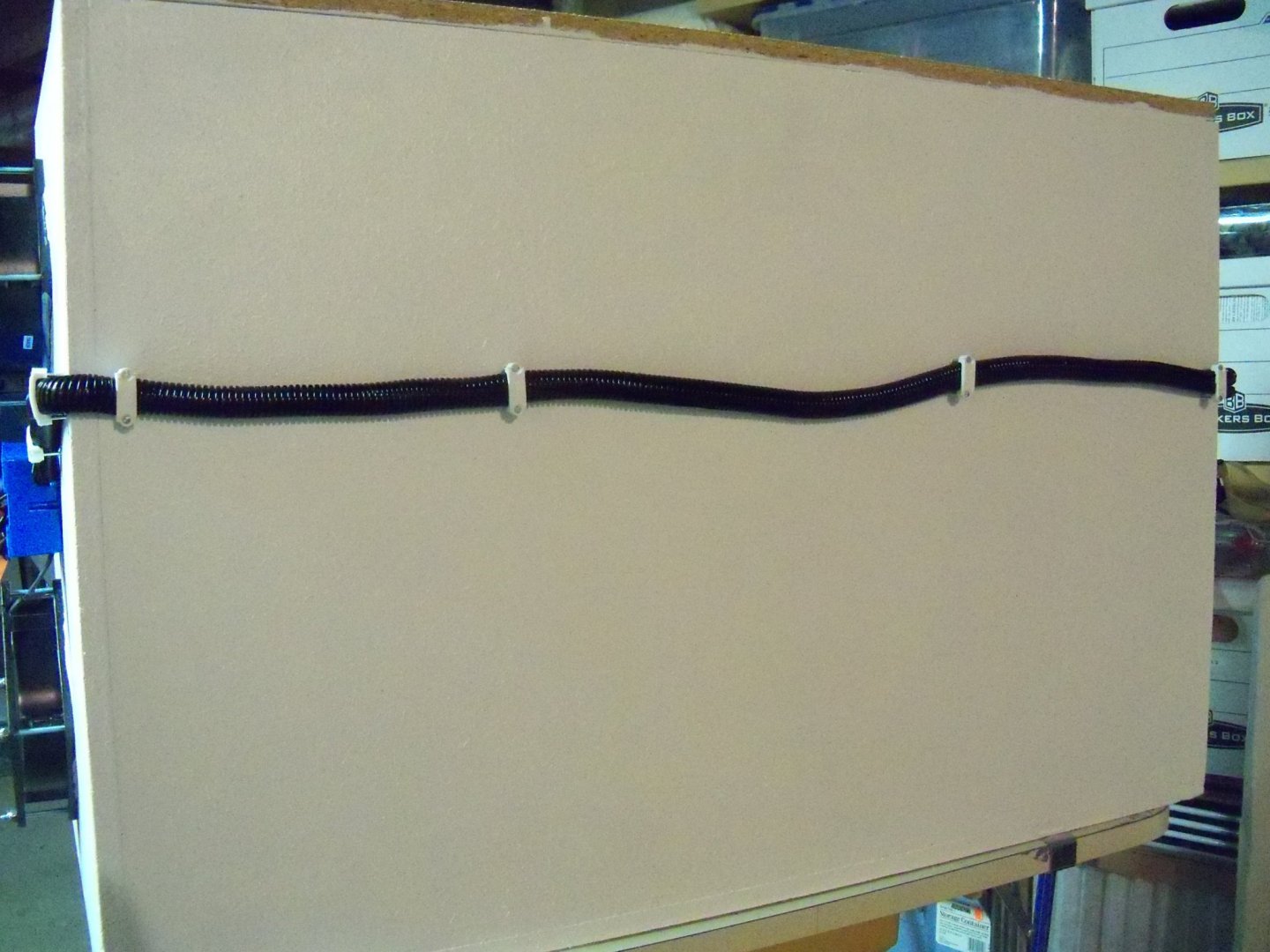
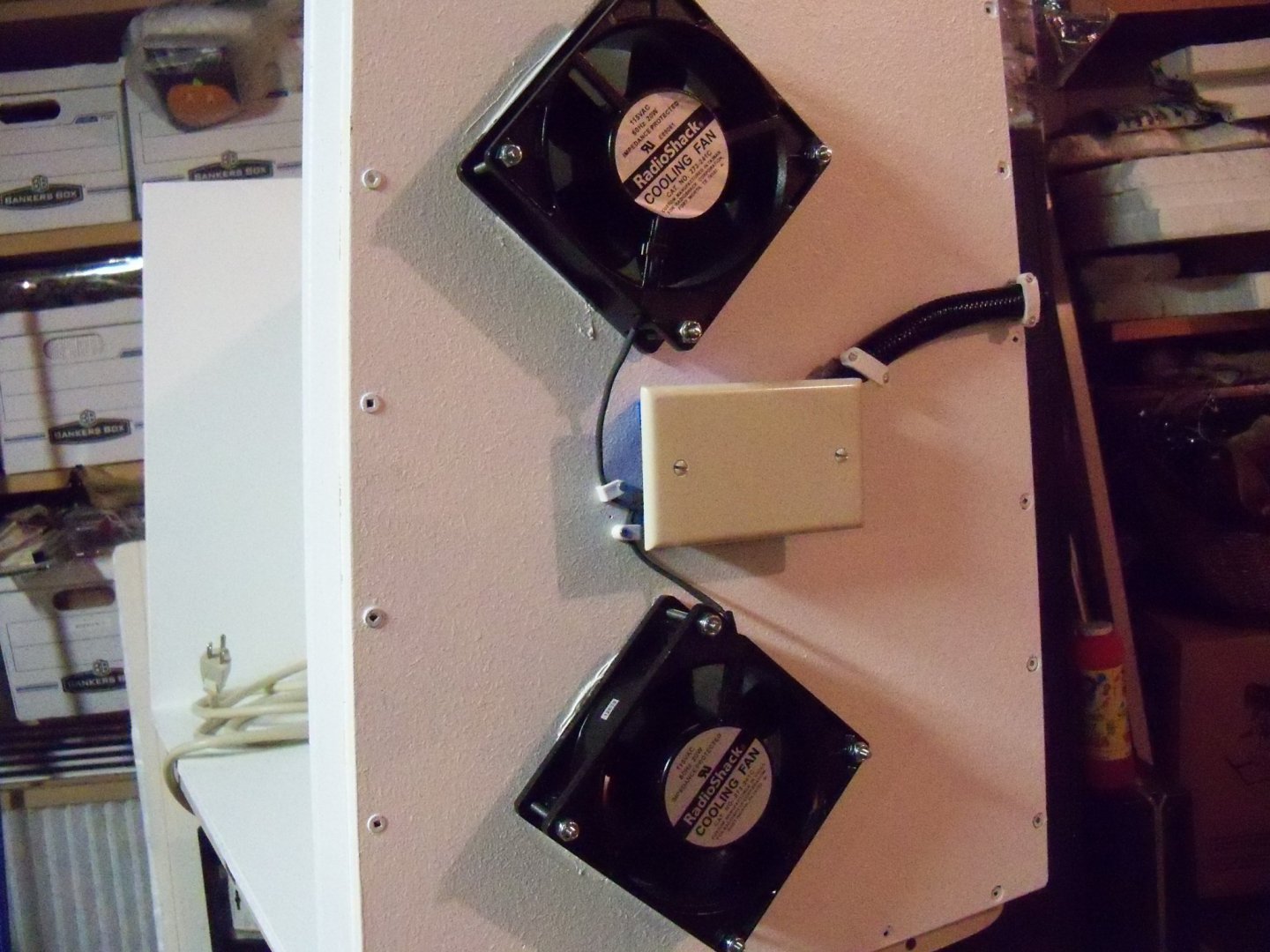
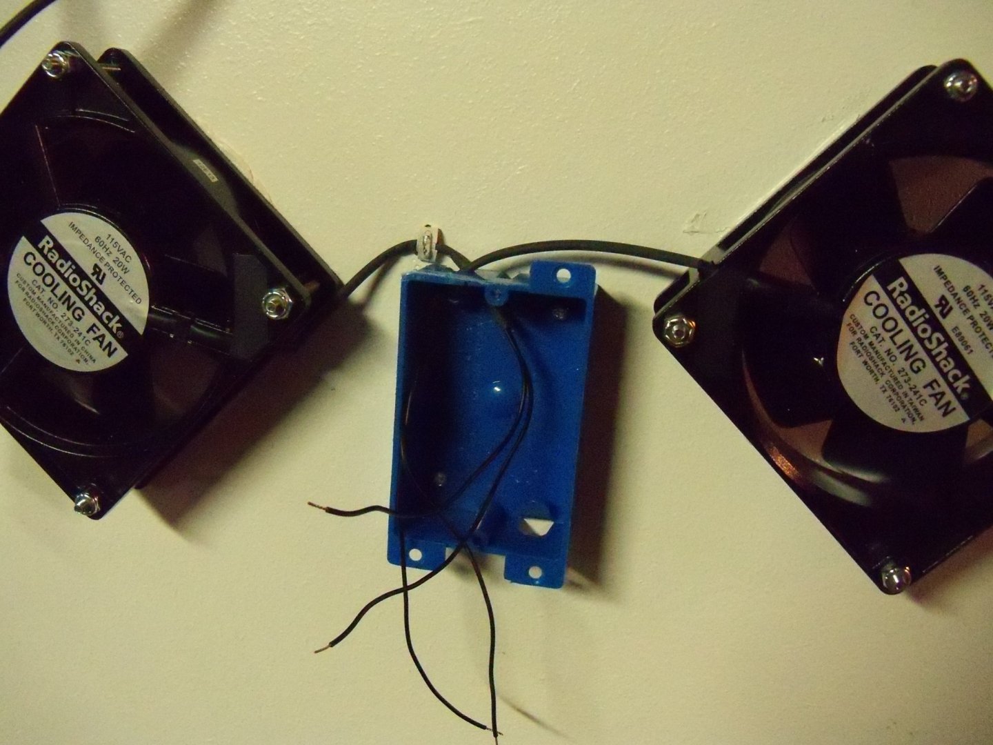
Taking my hinges for the top panel to my shop drill press, I clamped it in place to drill additional holes for all of the hinge leaves. You can see from the sketch below that the holes nearest to the hinge pin would be too close to the edge of the top panel and would end up in the foam weather strip on the top edge of the back panel. Since the hinges came in pairs of two, I decided that four hinges would be better anyway. The hinge pins are a rather sloppy fit, but by using all four of them it should help to reduce some of the slop. Returning to the electrical hookups, the fan wires were spliced in the plastic electrical box with wire nuts and given two coats of the liquid electrical tape. The cords for the fans were encased in some flexible plastic cord organizer to further protect them. The organizer was securely attached to the booth with several staples running across the back and left end panels of the booth to the power strip. Once the second coat of liquid electrical tape in the splice box set for 24 hours, the wires were pushed back inside the box and a blank cover panel was installed. The next thing to tackle will be making the top cover.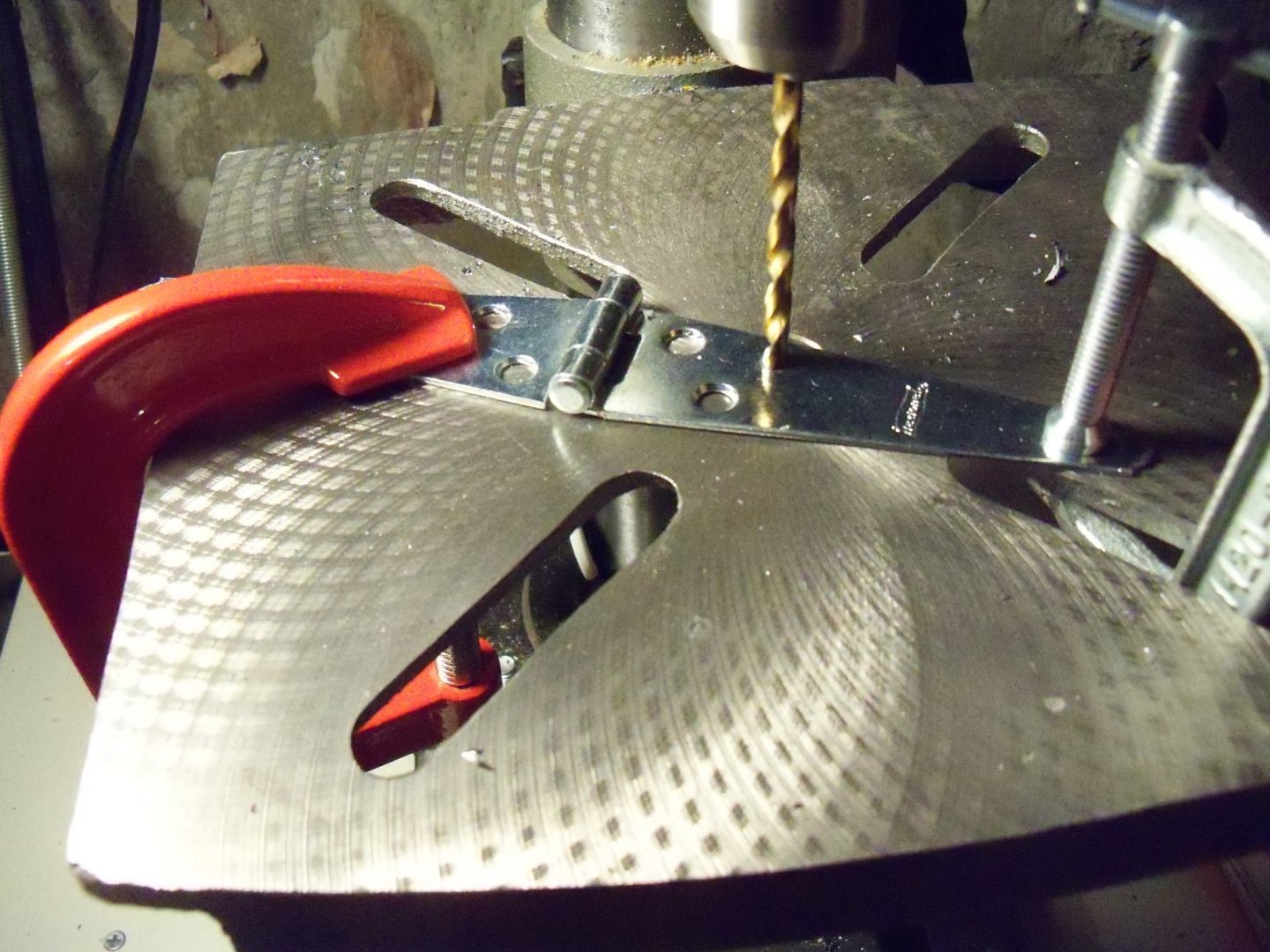


-
Homemade Spray Booth
BETAQDAVE replied to BETAQDAVE's topic in Modeling tools and Workshop Equipment
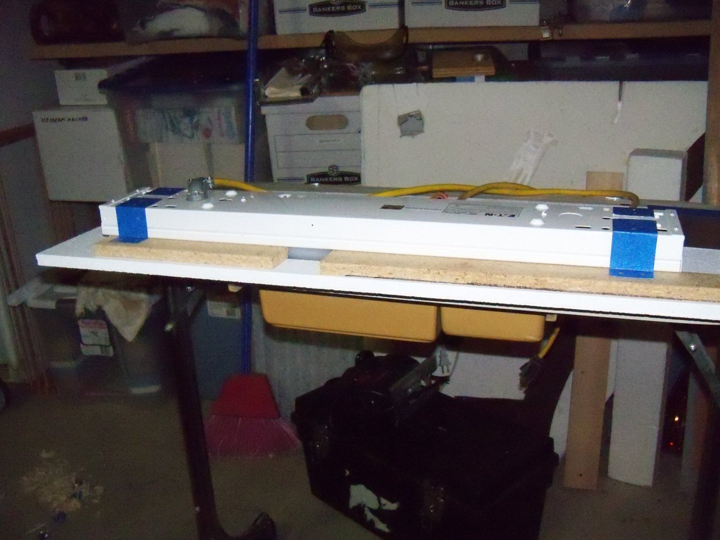
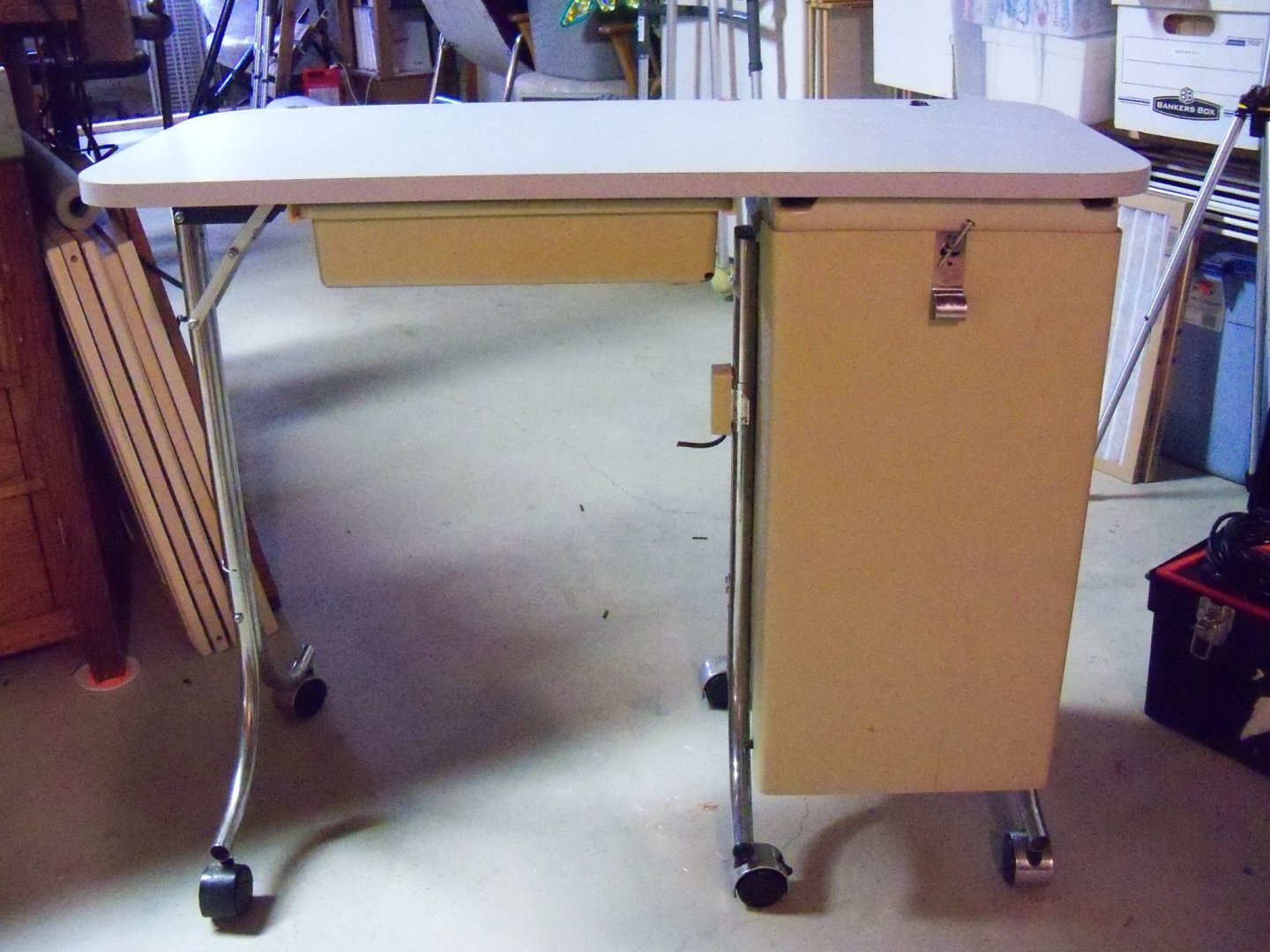
Mark, despite its rickety appearance, it is quite stable and easily capable of supporting the booth. After all, I have been using this four legged version of the cart shown below here to build the booth. The primary advantage of this four legged cart is that the legs can be fairly easily shortened with a pipe cutter. However, it doesn't have the drawer section for storing all of the air brush accessories. If push comes to shove, I could probably fashion some sort of shelving to attach to it, but there's quite a bit more work involved for that. Essentially, my choice depends on the optimum working height for using the booth. If I do have to shorten it, it can only lower the center of gravity and thus make it even more stable.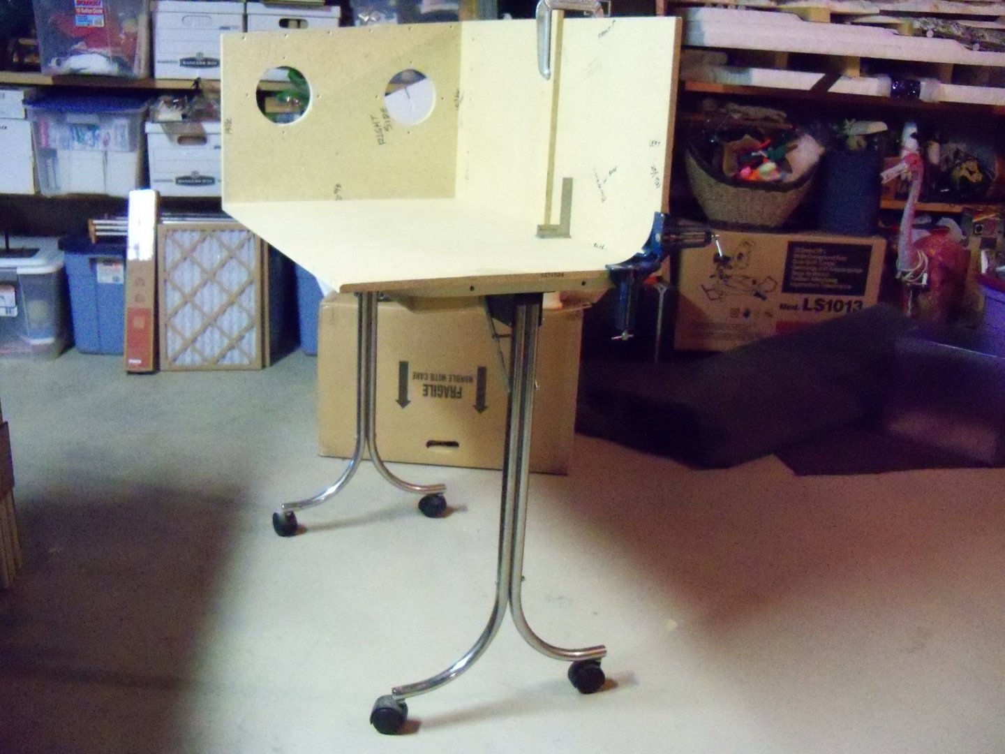
-
Homemade Spray Booth
BETAQDAVE replied to BETAQDAVE's topic in Modeling tools and Workshop Equipment
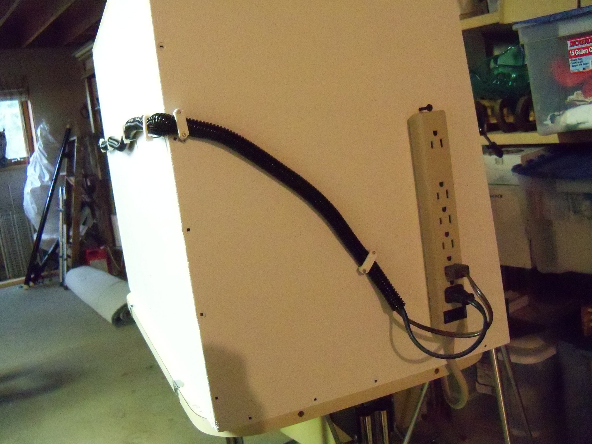
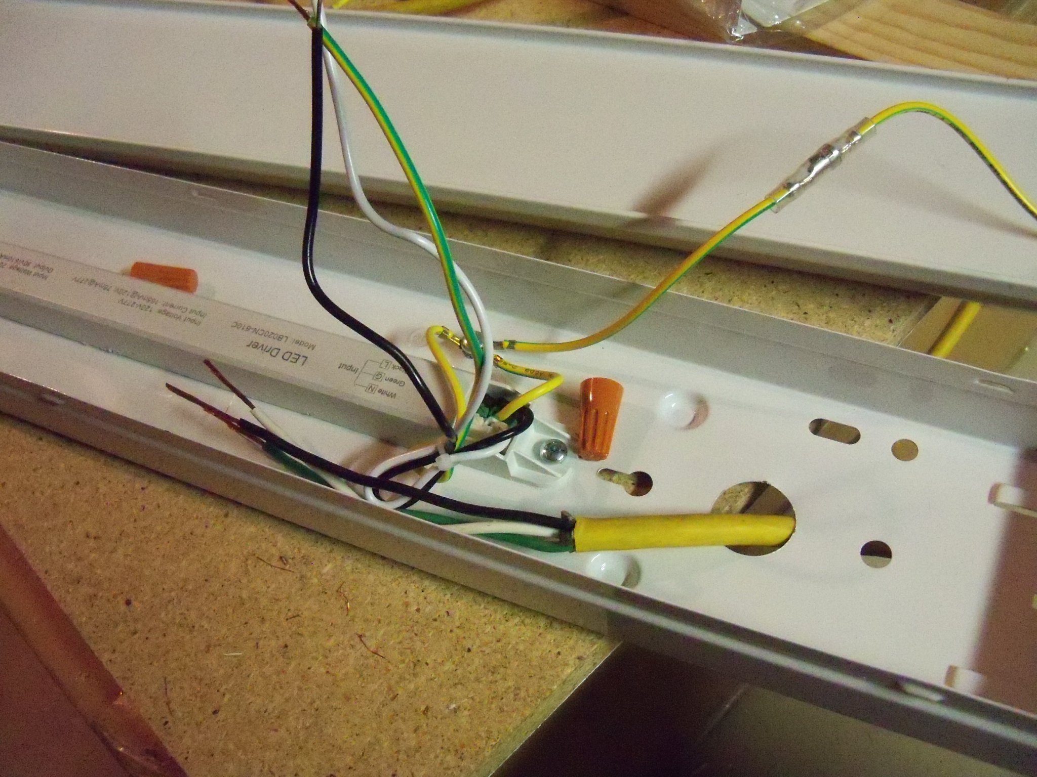
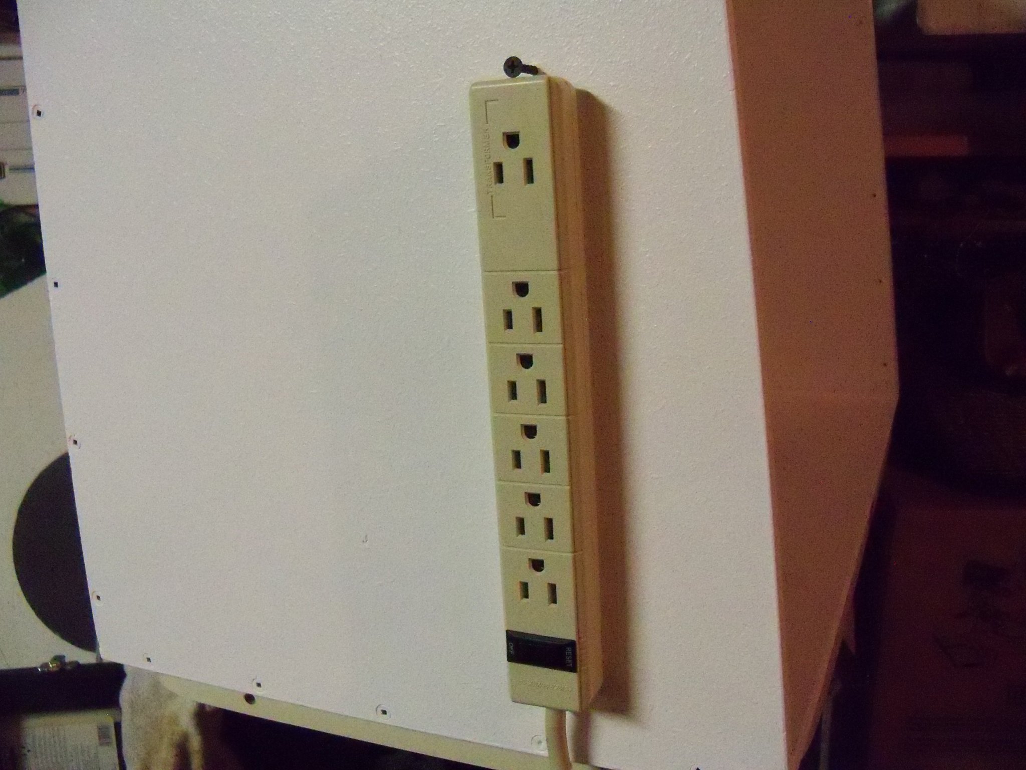
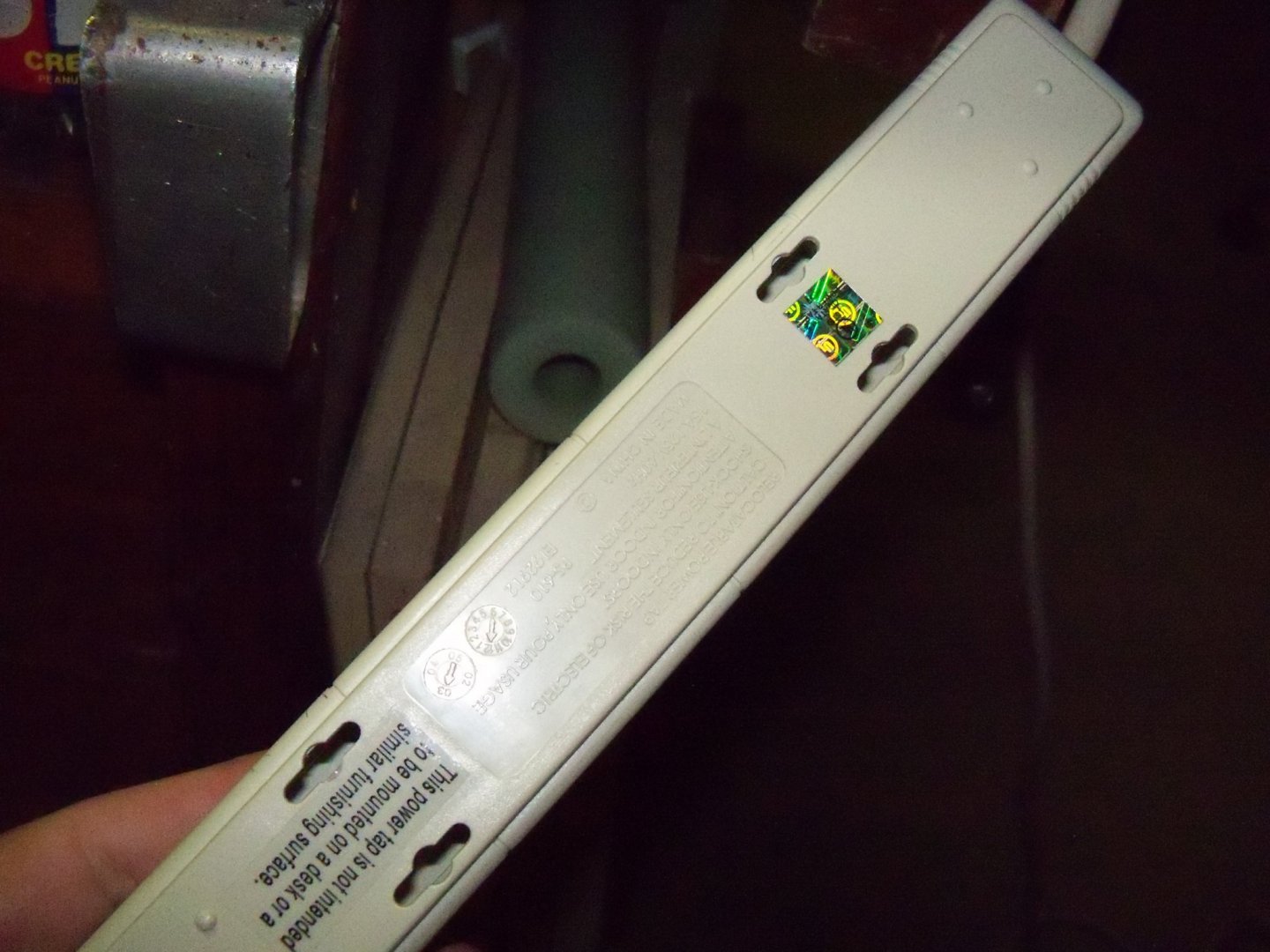
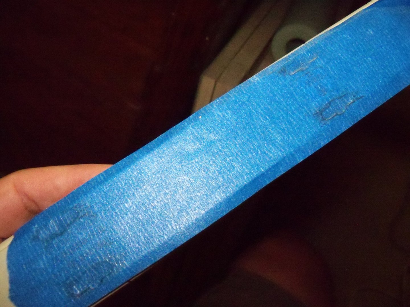
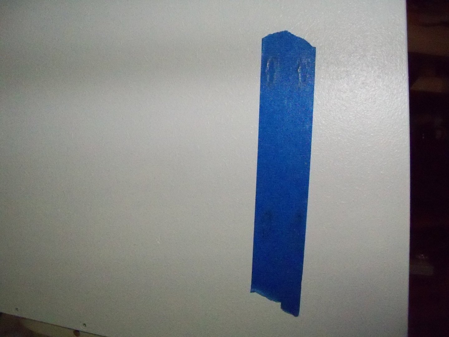
This is the cart that I’m thinking of using for my portable paint spray booth. It is quite light and somewhat shaky, but with the weight of the booth itself and a little reinforcing I think it would work OK. It is similar to the cart that I am currently using to make the booth, but it has a drawer section on the right side with five removable pull-out plastic drawers. There is an easily removed protective cover panel that prevents the drawers from sliding out, so anything inside should stay put. The bottom drawer could readily be replaced with a shelf to accommodate my sprayers’ compressor. The only reservation that I have with it is the height. I feel that since I am in a wheelchair, it may set the booth too high for convenient spraying, not to mention opening it up to change the filters. Unfortunately, shortening the legs could prove to be unfeasible. So I guess I am curious to know how the fortunate ones that can stand up use theirs. Does your booth sit just above your waist or higher? The cart that I am using to make the booth has no drawers, but the legs can be readily shortened to whatever height would work the best. I will continue to be open to any thoughts on the mater since I can still work on the other facets of this project. Meanwhile, I am working on the electrical features. The light fixture shown here is next. Using an old three wire extension cord, since the fixture needed a ground wire, I cut it off at roughly 18 inches from the plug. The other end was stripped back to expose the three wires. The cord was run through a 90 degree cable clamp and securely clamped it in place. If you notice in the photo, the fixture wires are solid, while the cord has stranded wire. The solid wire had about ¾” exposed, so I left about 1 ½” of the stranded wire exposed. That allowed me to twist the stranded wire tightly around the solid wire with my fingers. Then I trimmed the end to fit into the wire nut and twisted that until it was tight. Once all of the wires were joined together the nuts were turned down to allow me to seal the connection with the liquid electrical tape shown here. Now I proceeded to mount a switchable power strip on the front left side of the booth. As you can see, it mounts with the keyhole system, so locating the screws to match needs a technique that I learned long ago. Using a strip of painters tape stretched over the holes on the back, I rub a soft leaded pencil over the holes, which gives me the location of the holes. Now the tape is applied to the location selected for the power strip. Now holes are drilled through the tape and the appropriately sized flat head wood screws are installed. The tricky part is to adjust the amount of screw exposure to give a firm attachment. Once the strip is attached, I have learned through experience that an additional screw needs to be installed to prevent the power strip from slipping out of the keyhole slots as shown here. I got a start on the fan wire hookup. A plastic electrical box was screwed to the booth between the two fans. The wire between the box and the fans was wrapped heat shrunk plastic wrap to protect the wires and I nailed some cable staples to anchor them just before entering the box. Times up, so I guess I’m done for now.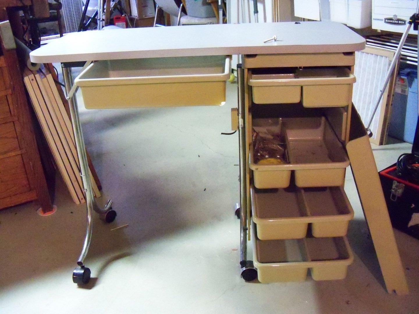


-
Sad news indeed. Hate to click the like button for the notice, but it does some amount of good to acknowledge a man for his contributions to his family, friends and our modeling community at large. R.I.P. Mitch.
-
Shop Fire Extinguisher
BETAQDAVE replied to Roger Pellett's topic in Modeling tools and Workshop Equipment
“What---Me Worry?” As John says “preparing for the worst and hoping for the best” is a much better philosophy than that of Alfred E. Newman of Mad Magazine fame. Due to various materials and equipment being used there, the potential for fire in this area is probably one of the highest in your home. You have saw dust in the air along with volatile vapors from paint, stain or varnish, working with caustic chemicals that require protective gloves and masks. Then you have ignition sources galore from open flames for soldering, shorts from electrical equipment, the pilot lights in your water heater or furnace, or heaven forbid, a smokers cigarette. Other than that, I can’t really see any reason for having one or more readily available. -
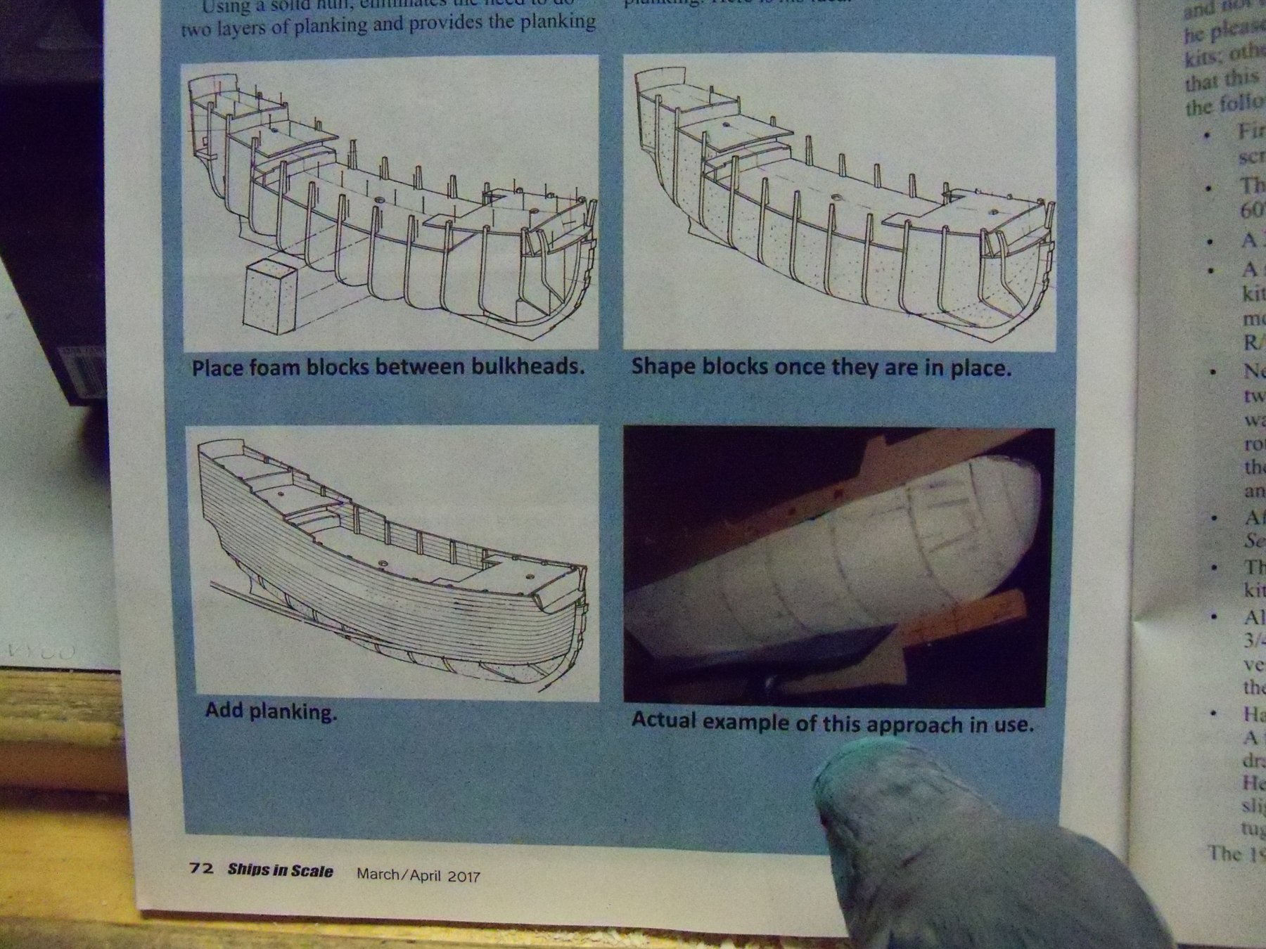
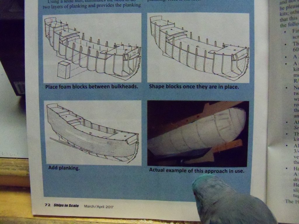
Here is an article that I posted back on April 13 in the Filler Block topic under the heading Building, Framing, Planking and plating a ships hull and deck. When I first saw this posting of this topic, I was reminded of seeing that in the March/April issue of Ships in Scale there was a short article on converting POB construction to solid hull construction by Robert Brandt. In his article, he described his method of using foam blocks to fill in between frames allowing him to use a single layer of planking that would have continuous solid support and eliminate the problem of hollow spots in between frames. (Something quite important if you intend to use a natural finish rather than painting the model.) He thought that by using extruded polystyrene foam for his blocking, the ease of cutting and shaping the blocks was easier than using wood. As an added bonus this would add very little in terms of weight. The excellent compressive strength of this type of foam doesn’t hurt either. Shown below are the illustrations of his method that were shown in his article. (Currently being reviewed by my assistant.) A version of this type of foam that is readily available throughout North America is Dow Blue Styrofoam. STYROFOAM™ Brand Insulation is the original extruded polystyrene foam insulation, invented by Dow and first manufactured by them in 1941. Dow's blue colored extruded polystyrene Blue Board's closed cell structure and lack of voids resists water and water vapor penetration thus protecting underlying materials from water damage. This product is also available in several sheet sizes and thicknesses and is relatively inexpensive. It does however, require the use of a particular type of adhesive, as some types of adhesive will dissolve the board. There is also very little in the way of shrinking or expanding due to temperature, so once it's in place it would be very stable.
-
As much as you enjoyed working on this ship, I for one, have enjoyed watching it progress just as much. That was one fine job and I hope to follow the progression of your next one.
-
Homemade Spray Booth
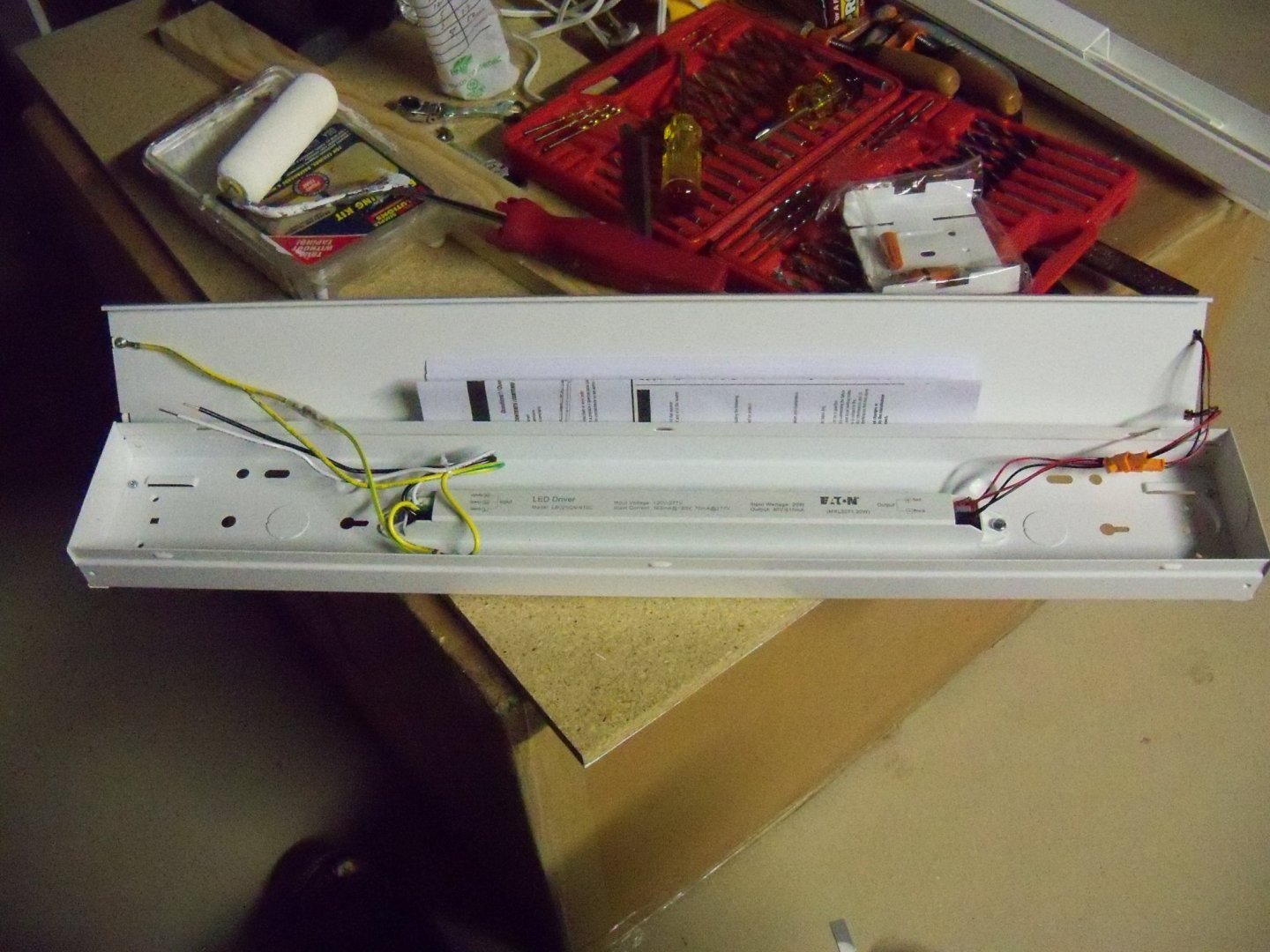
BETAQDAVE replied to BETAQDAVE's topic in Modeling tools and Workshop Equipment
My booth wiring setup will be somewhat changed from the original design, due somewhat to being wheelchair bound, I will mount the power strip on the forward edge of the left end panel. (If I put it on the top as in the original, the switch would be out of my reach.) Modified extension cords will be run from both the fans and the light fixture back to the power strip. Here are photos of the LED twin light fixture that will be used. As you can see, the fixture needs to have a plug with a ground wire, so I have taken an old three wire extension cord and cut the wire off at about 18 inches from the male plug end. (Using a replacement fitting to terminate the wires is something that is hard to assemble and leaves a lot to be desired anyway.) The other end will be spliced and anchored inside the fixture. From there the cord will be run out of the back of the fixture towards the back edge of the top, anchored there and run loose around to plug into the power strip. As in the original design, I will need to make up a pair of metal brackets to attach the fixture to the top panel that will allow the LED bulbs to sit down in the cutout for the light. Putting the power strip on the opposite end of the booth, means that the wire leads to the fans will have to be run all the way around the backside of the booth. To do this, I cut a pair of two wire extension cords off at 36 inches from the male plug ends so the plugs could be used as is with the cut end spliced to the fan leads. Since the terminals inside the fans are not accessible to connect the extension cord wires to, I need to splice them directly to the lead wires extending out from them. I don’t want to leave the splices out in the open, so I will make the splices inside a junction box and clamp them in place. From there the cords will be anchored to the back of the booth, leaving enough slack to allow them to plug into the power strip. All of the splices will be twisted into wire nuts and coated with liquid electrical tape that I picked up from Micro-Mark. At present I am modifying the hinges for the top panel and contemplating modifying one of my rolling carts to use for making the booth portable.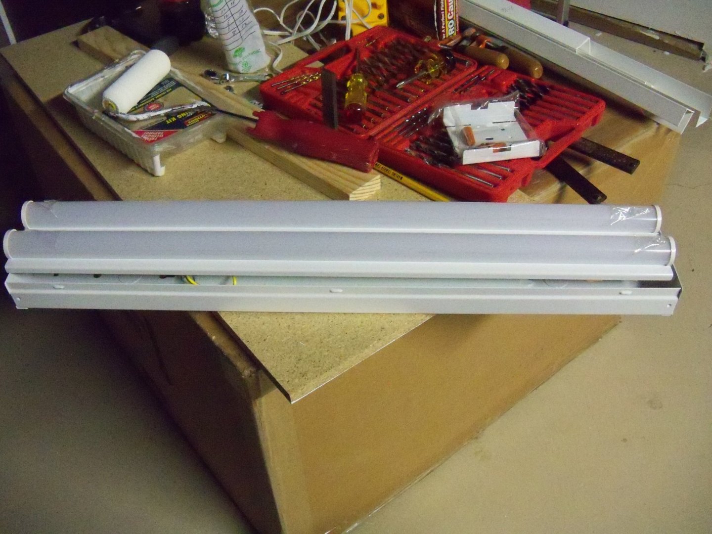
-
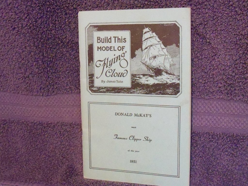
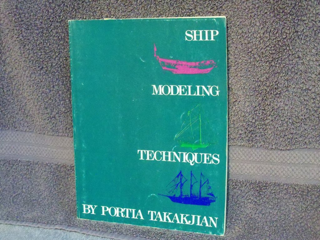
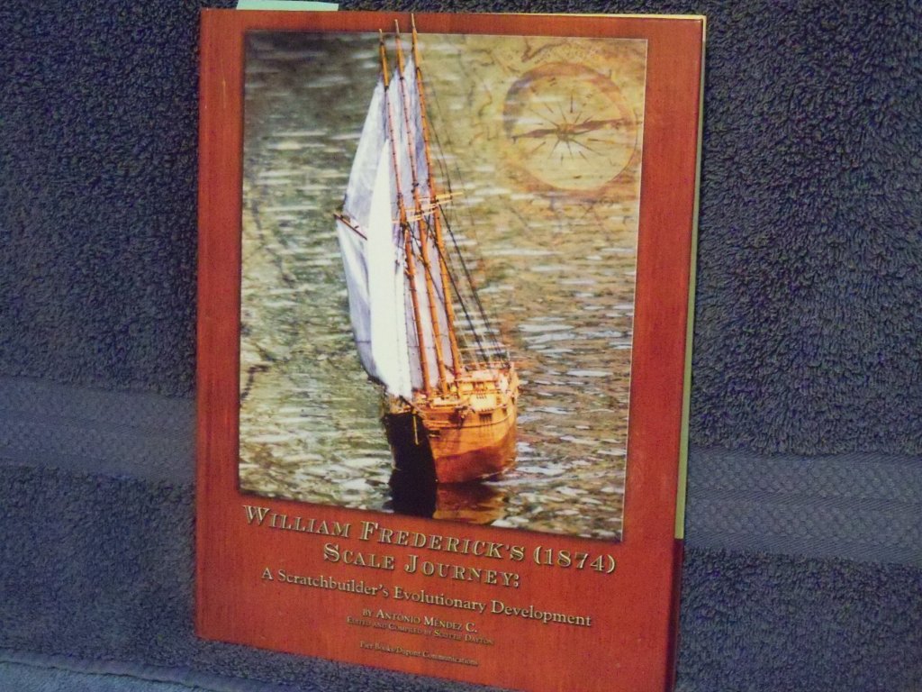
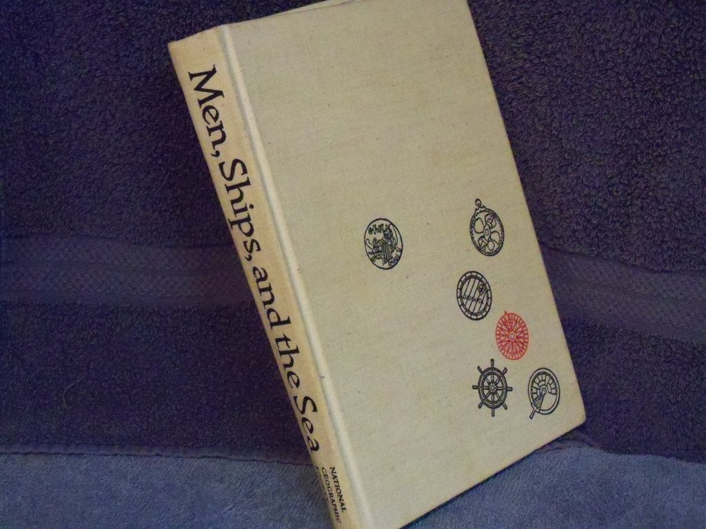
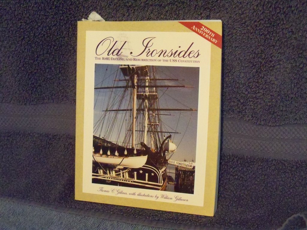
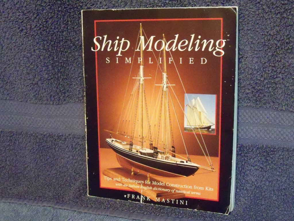
Getting back to your original question: I'm going to spend some money on reference books so I'm curious which books MSW members consider to be essential for a ship modeler's library (other than MSW itself). I have a few other publications in my collection not mentioned previously that I would recommend. The first one shown below is a very good guide on scratch building a clipper ship that I have used many of his techniques when I built my 1/6” scale Wanderer. This paper pamphlet I have shown above is of a 1928 Popular Mechanics magazine by James Tate who was the Technical editor of the magazine. It has a set of plans and instructions on scratch building an 1/8” scale model of the clipper ship. It is no longer in print, however if you Google the title it brings up the site early plans for making a model – sobco. There you will find access to a reprint of the booklet at the bottom of the page, and just above that are clearer copies of the actual blueprints. The model is shown as a bread and butter style solid hull. One reason that I liked it so much was that he used nothing more than a few hand tools that I had at the time. So if you don’t have much in the way of tools, a handsome ship model is still within your grasp. This next one titled Ship Modeling Simplified by Frank Mastini is a wealth of tips and techniques for building plank on bulkhead model kits. Then I have Ship Modeling Techniques by Portia Takakjian. She describes the construction of three different models with three different techniques for the hulls. The royal yacht Fubbs is done plank on frame. The Hudson River sloop Victorine is done with a solid block of wood. The last ship is the research vessel Vema which used the lift method. While the hulls vary, she goes into making many of the details commonly found on many different vessels. One of the hardcover books that I have read and reread several time is William Fredrick’s (1874) Scale Journey: A Scratch Builder’s Evolutionary Development by Antonio Mendez C. He was a master of taking discarded tools and converting them to other homemade tools and gadgets. His shop alone was a very innovative design. The book describes his construction on an R/C model of this ship. This last hardcover book is Men, Ships, and the Sea, a National Geographic publication by Capt. Alan Villiers. While this one doesn’t go much into modeling, I have found much inspiration in its pages to renew my interest in ships whenever it begins to wane. It covers the whole gamut of ships from the earliest vessels of tied together logs through the early wooden sailing ships, steel dreadnoughts of war, to the leisure craft of today. For people interested in specific ships I have these last two entries. The Pride of Baltimore The story of the Baltimore Clippers by Thomas Gilmore shown below gives a lot of the history and construction details of both ships I and II. Old Ironsides The Rise, Decline And Resurrection Of The USS Constitution by Thomas C. Gillmer is a publication that came out to celebrate her 200th anniversary. Here again, this shows many of the details as she was originally and all of the various revisions and repairs through the years. Anyone interested in building a model of this popular ship will find much of interest here. One more suggestion I would offer is to order the flash drives of Model Ship Builder and Ships in Scale that are available through MSW and the Model Research Guild, as there is a wealth of invaluable information in them.