HOLIDAY DONATION DRIVE - SUPPORT MSW - DO YOUR PART TO KEEP THIS GREAT FORUM GOING! (Only 13 donations so far - C'mon guys!)
×


BETAQDAVE
-
Posts
5,386 -
Joined
-
Last visited
Content Type
Profiles
Forums
Gallery
Events
Everything posted by BETAQDAVE
-
 Likewise. Looks like you've done quite abit of work on your ship since your last post Jesse.
- 1,306 replies
-
- 6
-

-
- syren
- model shipways
- (and 1 more)
-
Seems like I've heard that before from several drill sergeants in the service. (Among many other comments.)
-
This looks like the reincarnation of the rat pack! (Back in the day they were: Peter Lawford, Frank Sinatra, Dean Martin, Sammy Davis Jr. and Joey Bishop.) Which one is the ring leader (Sinatra) here?
-
It looks like you have a good start here. The only suggestion that I would have, is to reinforce the keel joints before you start the planking. Since the keel is not one continuous piece and it's essentially just joined with butt joints, I would glue reinforcing blocks of plywood to each face of those joints. (Similar to the blocks for the mast holes.) The frame would be both stronger and more likely to remain straight. To tell the truth, I am surprised that the instructions for these kits with multiple keel pieces don't suggest this simple piece of advice. A butt joint of such thin material is one of the weakest joints, regardless of that jogged joint line.
-
I think that I remember this ship! Wasn't she launched on April Fools Day back in 1701? As I recall, her first captain was the Court Jester.
-
Put a charge of black powder and one of those canon balls in it, and see if it fires off a round! It looks like it would work to me.
-
A most impressive first build regardless of your limitations.
-
If you can get a square head screw driver and square head screws they would also be easier for you. The bit won't slip out as bad as with those Phillips (X) head screws and you don't have to bear down on it so hard to keep the bit engaged with the screw head. Thus you can spare some wear and tear on your wrist. Of course you could always buy an electric or rechargeable power drill with a square head bit, but no sense doing that unless you plan on having a lot of screws to drive.
-
The next time you need to put screws in by hand, just remember to pre-drill a hole slightly smaller than the screw and coat the screw with a lubricant like wax or even bar soap. In the states we have a product called screw ease that comes in a metal tube which is specifically made for this, any hardware store would probably have a similar product. The screw can be driven with much less effort and as an added benefit the screw can more easily be removed if necessary.
-
Check out EdTs Young America posting part 312 from Nov. 23, 2018. He shows his unmounted yards for the mizzen mast including what he refers to as the Mizzen Monkey gaff. Then on part 319 from Mar. 2, 2019 he shows it mounted on the mizzen.
-
Harbor Freight Hardwood Workbench Kit Bash
BETAQDAVE replied to thibaultron's topic in Modeling tools and Workshop Equipment
You're right about that bit Ron. They originally were designed for use with an old school hand brace and came with a square end to the shaft. The screw portion was to make the bit pull its way through the wood and thus reduce the effort required to bore a hole. Later versions came out for electric drills but the other end still has a octagonal shaft to handle the extra torque on the drill chuck. They can be used with power but the drill speed needs to be greatly reduced to allow you better control. -
Harbor Freight Hardwood Workbench Kit Bash
BETAQDAVE replied to thibaultron's topic in Modeling tools and Workshop Equipment
Ron, you may want to attach a wide board or plywood panel across the back of the bench since you removed the front shelf support bar to give it more lateral stability if the bench didn’t come with one already. I would also suggest some sort of leveling device on the bottom of the legs to make sure your bench sits solidly on the floor and won’t wobble. I used large T-nuts with a heavy carriage bolt under the legs of a bench that I made for a friends garage shop so he could easily adjust it with a wrench. That system added less than a half inch to the height of his bench. Even some trimmed off wood shims would be better than nothing. -
Mike, check out the scratch build HMS ROYAL KATHERINE 1664 by Doris - 1/55 - Card. Sounds very much like the "foils" that she uses. Essentially it is a vinyl self adhesive tape available in a myriad of sizes, colors, and wood grain finishes. If that is the same product, I am currently using it on my whaling bark Wanderer to overlay the plastic hull.
-
Just came across this ship log and am impressed by the amount of detail that can be achieved at such a small scale! I have a hard enough time struggling with 1:96 scale. Two things struck me about those photos of this ship shown with its' battle damage that really stood out.. One, is that it was still afloat after all of those hits. Did the shells explode after piercing the hull or just cut through? I would have expected much more damage if they had exploded internally. And two, how on earth did they manage to turn such a huge ship upside down in a dry dock in the first place to repair the bottom of the hull without causing more damage. (Imagine if you were to take a large structure designed to be built upright like a building and could even manage to turn it over, the thing would just collapse onto itself.) I also seem to recall that the primary turrets were held down in their casements by gravity alone and would just drop out. They must have removed major portions of the superstructure prior to inverting the ship. One more thing that seems to be lacking to me as far as those torpedo nets go, is the fact that they didn't extend to protect the bow and stern of the ship. A torpedo strike in the bow would, if nothing else, dramatically decrease her speed. Likewise, a strike in the stern could leave her without maneuverability and driving power. These unprotected areas would seem to be more critical to the ships function than a strike in the middle where her armor belt was already the heaviest. If their primary function was to protect the ship from torpedoes while at anchor rather than when underway, a full length floating torpedo net system set up alongside the anchored ship would seem to have been more effective. (Like in Pearl Harbor for instance.) Perhaps those were some of the reasons that the WWII era capital ships no longer employed torpedo nets in their design.
-
Good luck, it looks like a good one to start out with. What company sells your kit? Hopefully it will come with a decent set of drawings and instructions. Some don't, but don't worry too much as MSW members are here to help out.
-
That's great Kortes! You can also make your own home made and/or modified tools.
- 306 replies
-
- 2
-
-
- schooner
- la jacinthe
- (and 1 more)
-
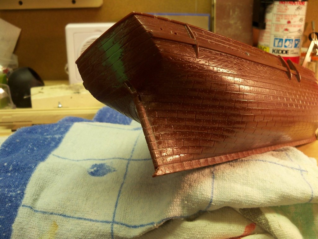
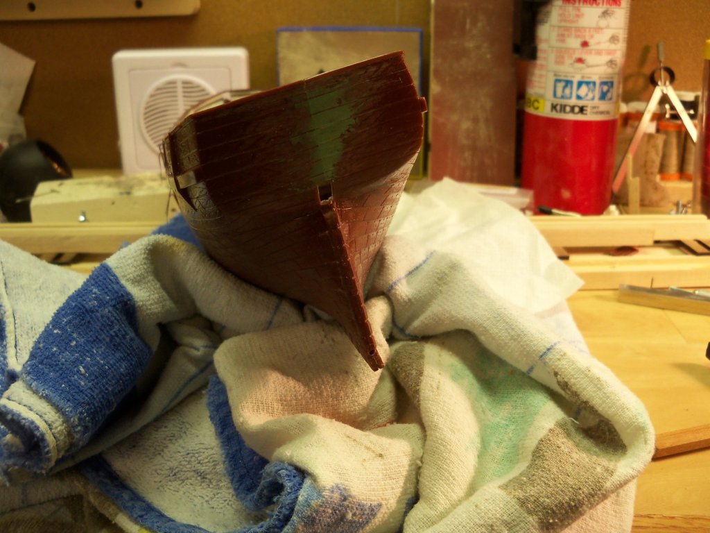
Been off a few days with other projects, but did manage to clean up the definition of the stern copper plates and the transom as shown. I guess the next step will be to form the pintles and gudgeons and get them put into place. That may take a while as I need eight sets of them soldered up. That’s more even tinier parts than the hawse pipes.
-
While this method obviously works well for you, I am wondering why you don't just make the frames, fill the spaces solid with blocking, shape the hull and proceed directly to the finish planking rather than adding two additional layers of sub planking onto your solid blocked and shaped hull? It seems like a lot of additional work to accomplish the same result. Or is there a method to your madness? Because as I can say there is no denying the quality of your results.
- 306 replies
-
- 2
-
-
- schooner
- la jacinthe
- (and 1 more)
-
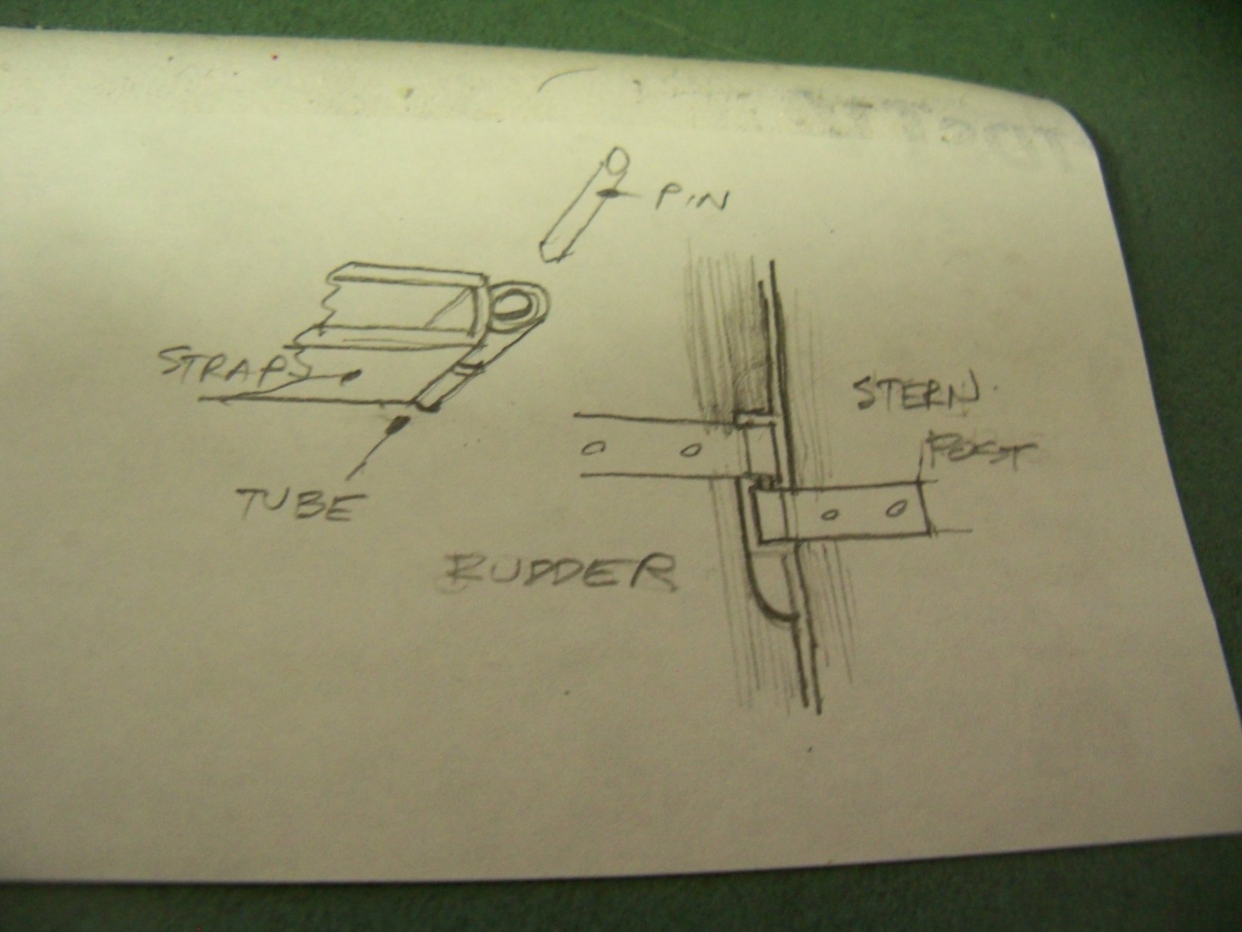
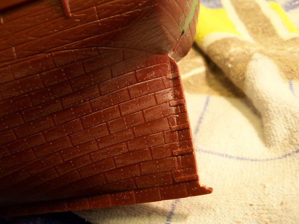
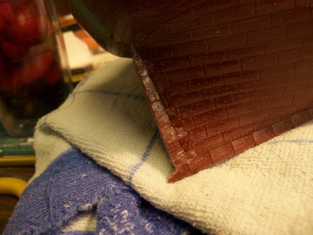
The rudder is OK for now but that brings me back to making the pintles and gudgeons to match my sketch. Of course, before I can do that the first step required is to remove the plastic straps on the stern of the hull. The removal was done slowly with several different scalpels and was fairly straight forward, however the tricky part was to remove the straps without ruining the appearance of those copper plates on the hull and stern post. Besides all that, the hull is rather awkward to handle right now, and I can see that it would have been easier if I had done it while the hull was still in two pieces. Isn’t hind sight wonderful? Here is a photo of the offending gudgeons that need to be removed. And here is one side removed. It still needs a little touch up to restore the definition of the copper plates. However, that is a job to handle tomorrow!
-
These hooks are outstanding, too bad I work with 1:96 scale and these would really be tough to duplicate.
-
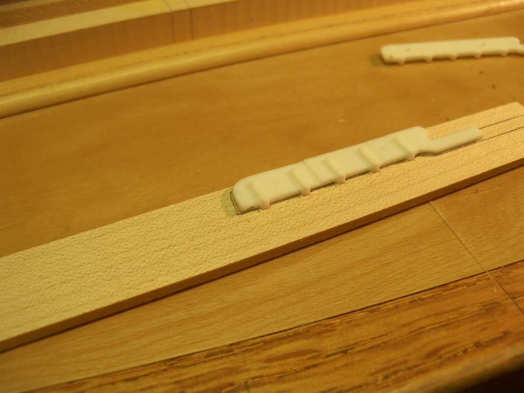
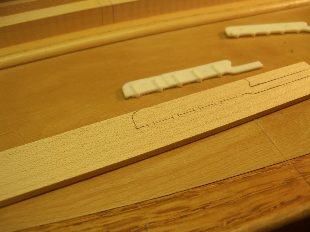
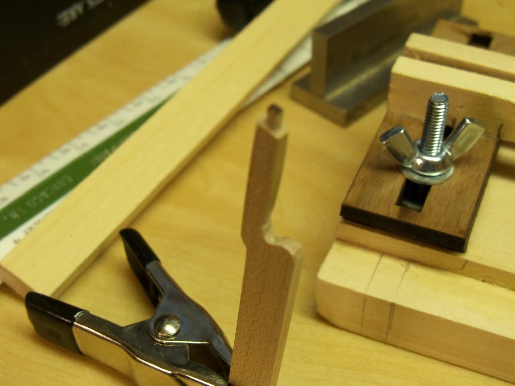
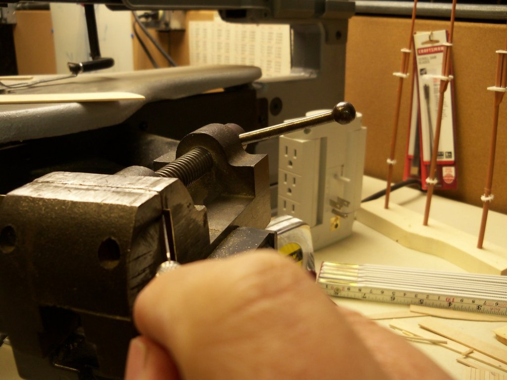
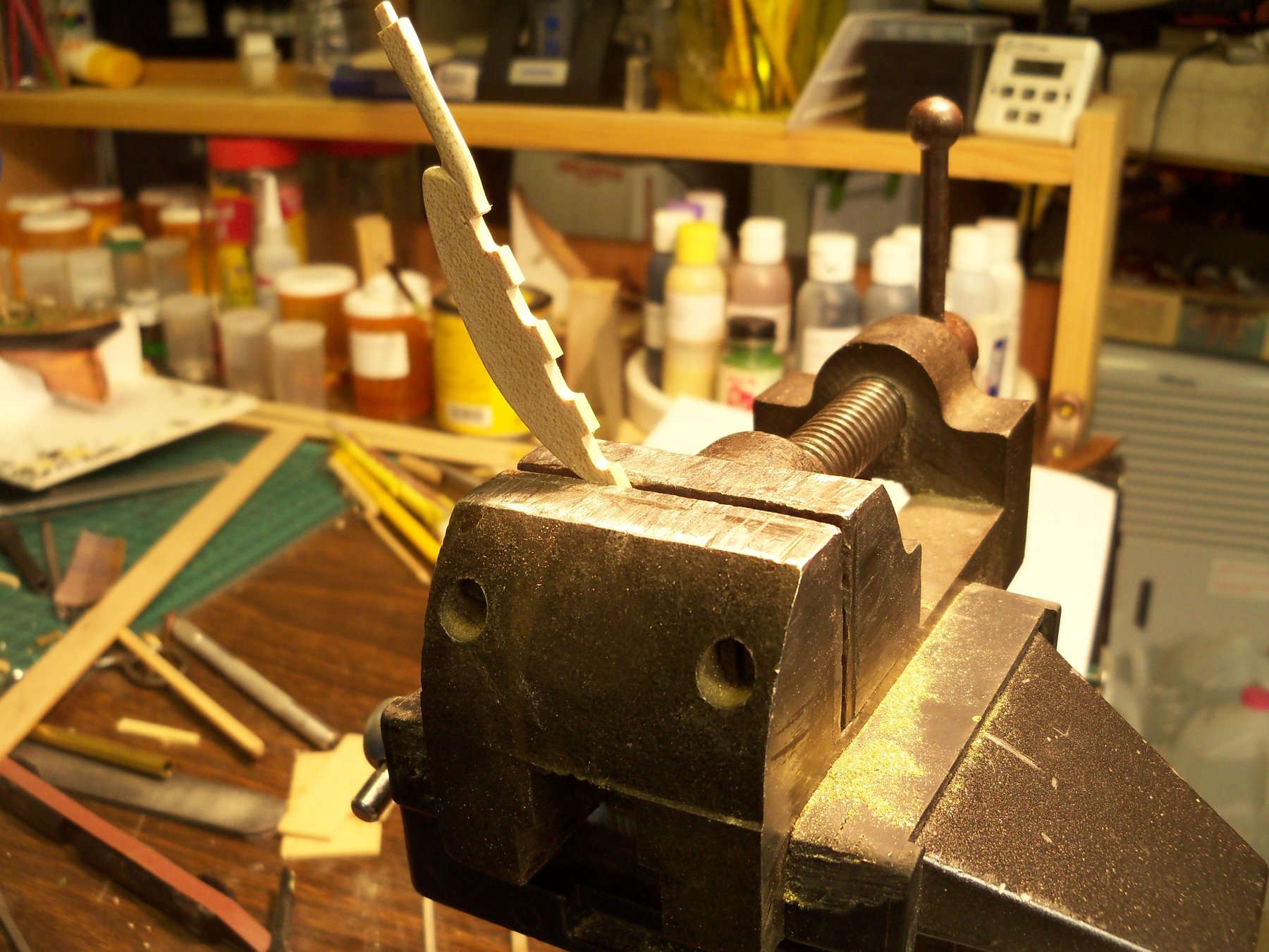
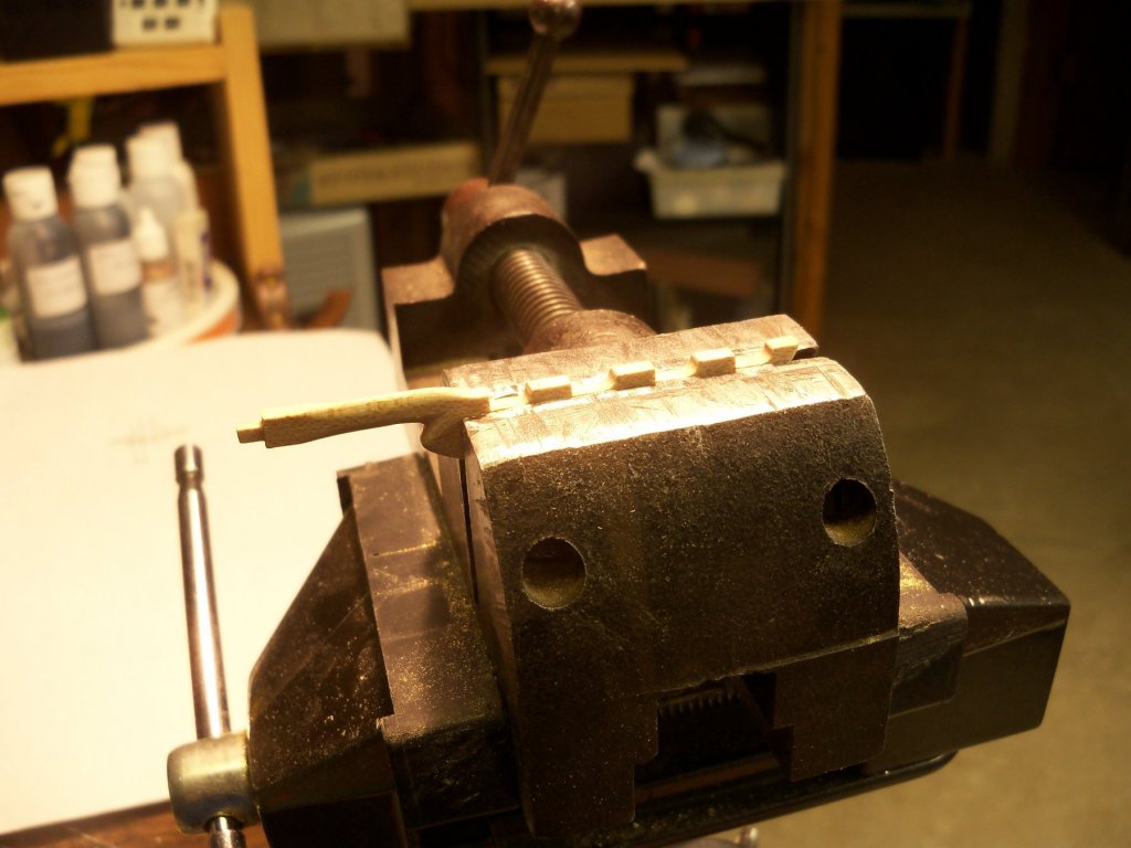
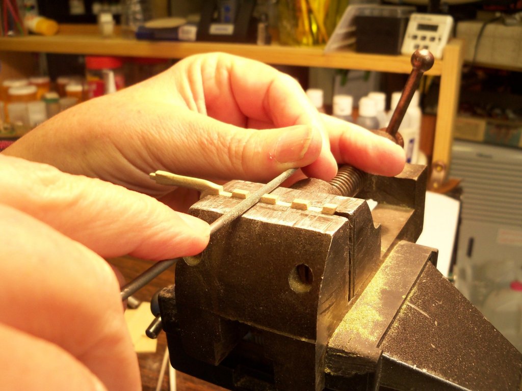
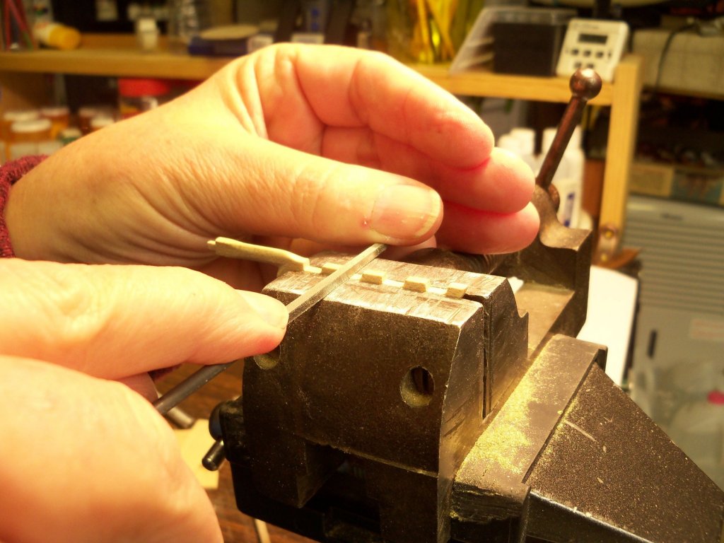
Well, it was kind of a judgement call on my part as to the shape of the new rudder. I just tried to duplicate the new shape as best I could since the photo was at a difficult angle to make any measurements from. I made the upper portion of the rudder the same including the tenon at the top. I made the bottom just wide enough to still attach a pintle and made a smooth curve for the remainder with a slightly wider bulge toward the bottom. The kit didn’t make a very accurate representation of the pintle and gudgeon joints either. So, making a lot of extra work for myself, I decided to remove and replace all of the straps from both the rudder and the stern post. Below is a comparison between the kit original, my first rejected wood duplicate, and my current version taken from the photo mentioned in the last post. I had also noticed that other ships about the same size as the Wanderer had fewer hinge points than shown on the plans and the kit, so going with just four seemed more suitable and left me with a little more room for longer legs on the bottom pintle, not to mention more space between the hinge points. Taking the new rudder to my vice, I did just that by dividing the edge into in four equally spaced notches and making a sketch (shown below) of how each one would be represented. I made eight cuts with my razor saw to the depth set by the vice jaws. The spacing between the cuts was made twice the width of the strap and then cleaned out with a scalpel. The bottom edge of the notch was extended and cleaned up with a round file, leaving an overall space of three times the width of the straps. And finally the top of the notch was cleaned up with a square one. Here is the result to this point.


-
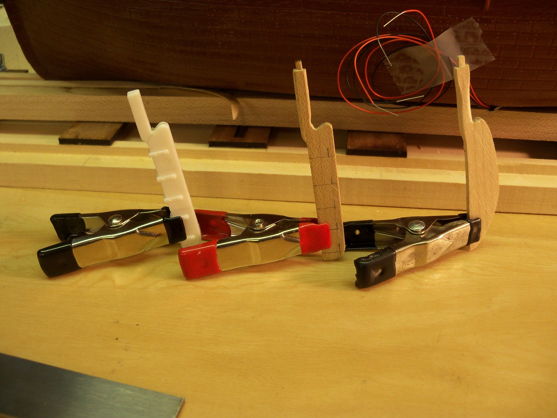
Holding small parts for soldering
BETAQDAVE replied to BETAQDAVE's topic in Metal Work, Soldering and Metal Fittings
And here I sit with a big roll of that aluminum tape right here in my shop! Who knew? -
And yet, the deadeye at the bottom is correct! Maybe it's just him using artistic license.
- 449 replies
-
- 4
-
-
- sultana
- model shipways
- (and 2 more)
-
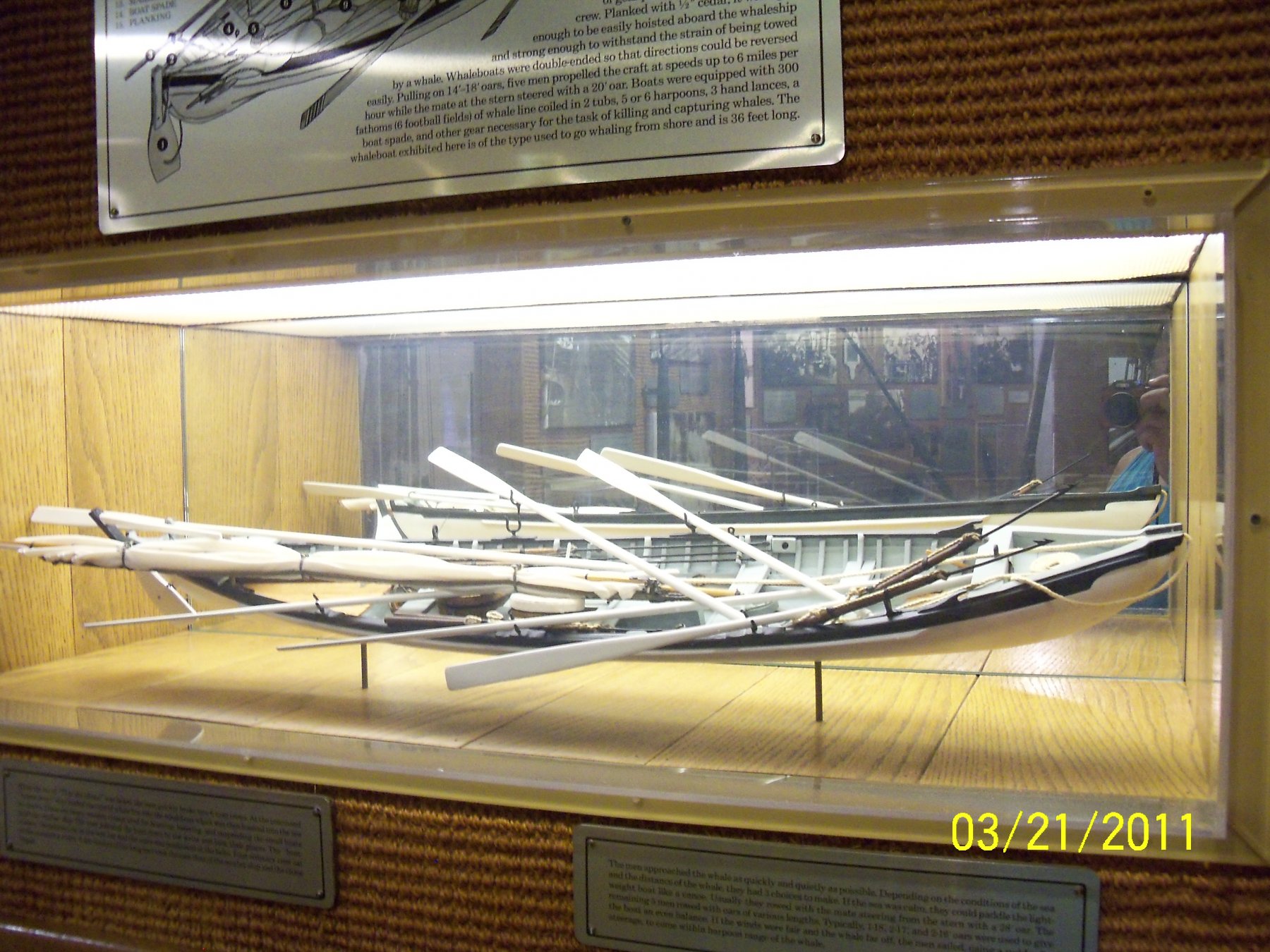
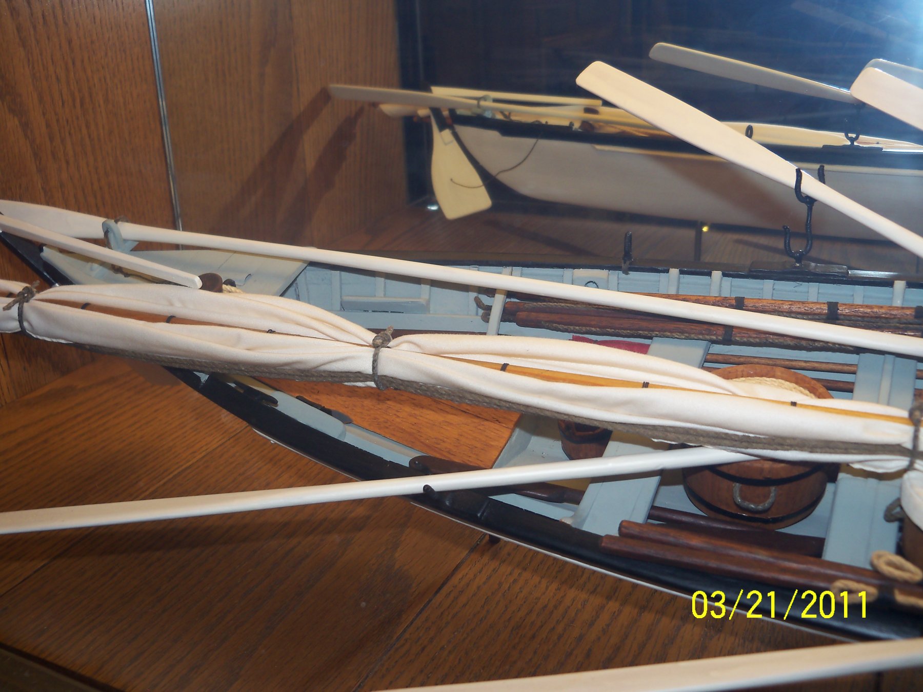
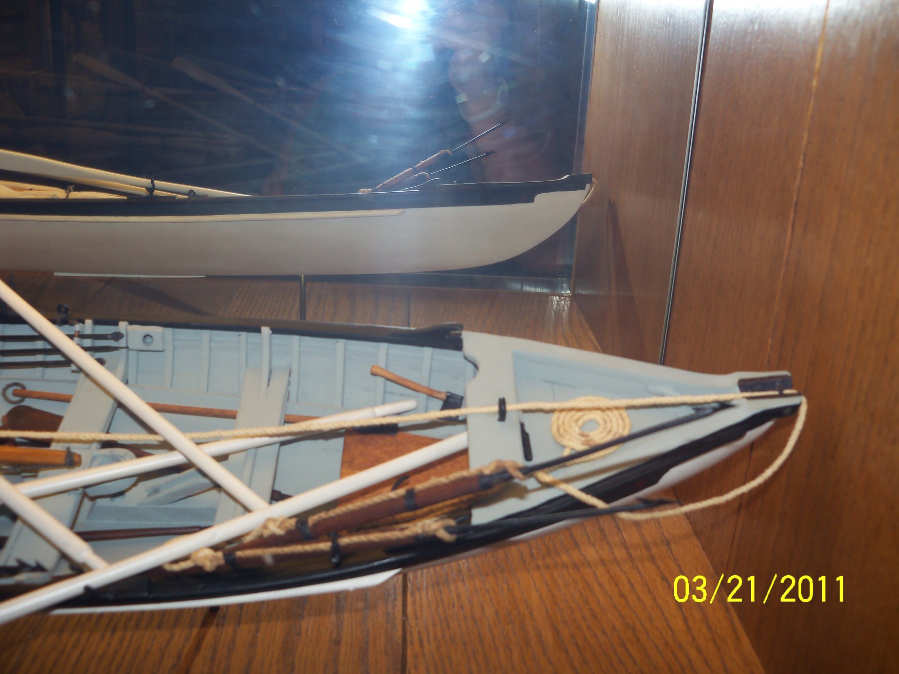
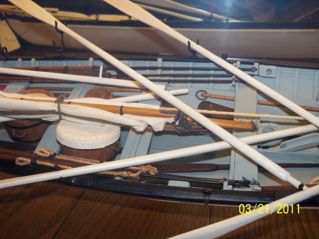
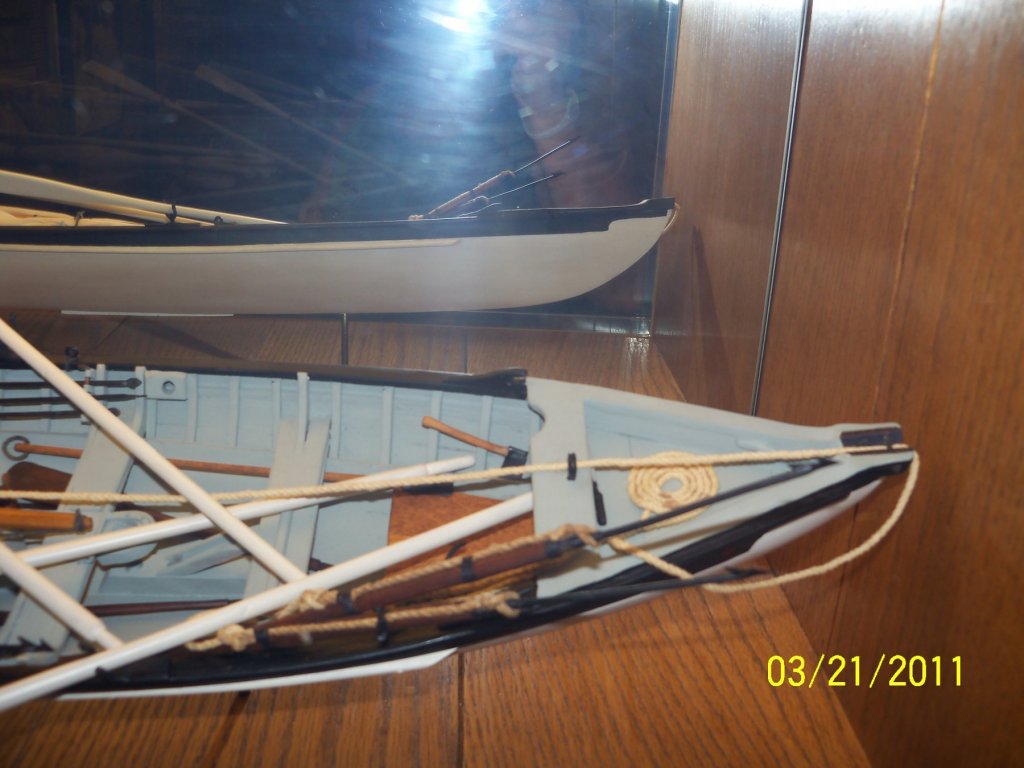
The best display that I ever came across of a whaleboat was this 48" long cased model in the Whalers Museum on Maui while there in 2011. It was an example of a 36' long later day boat with a centerboard and carvel planking. This particular boat in the exhibit was of the type used to hunt whales from shore so I was not sure if there were differences between this and the boats carried on ships. Anyway, I thought that it was a rather unique way to display the model with a mirror in the back to allow viewing it from both sides. They also had a full size replica on display outside, but the equipment was not aboard and I was not able to find any photos of it anyway. Standing beside it though, I thought that it was a little unnerving to think of going out in the open ocean to hunt these huge whales in such a small boat with so little free board. I was reminded of when sheriff Brodie in Jaws gets a close up and personal view of the shark and says "I think we need a bigger boat!"


-
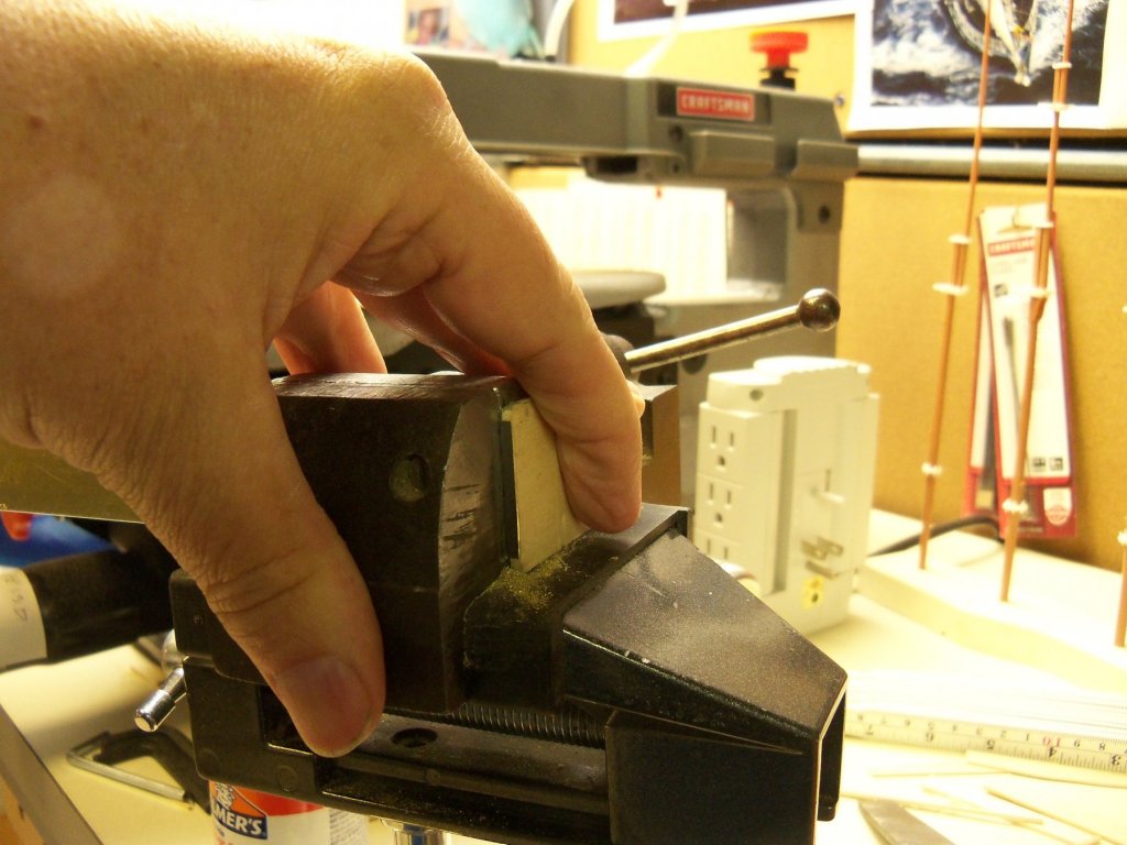
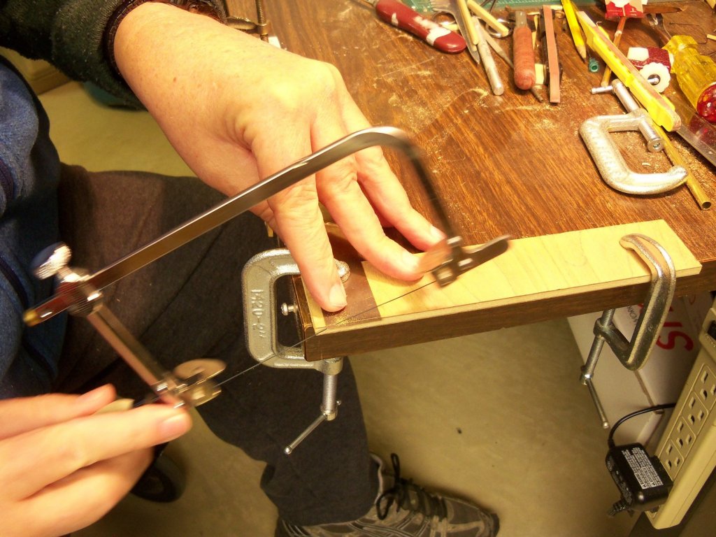
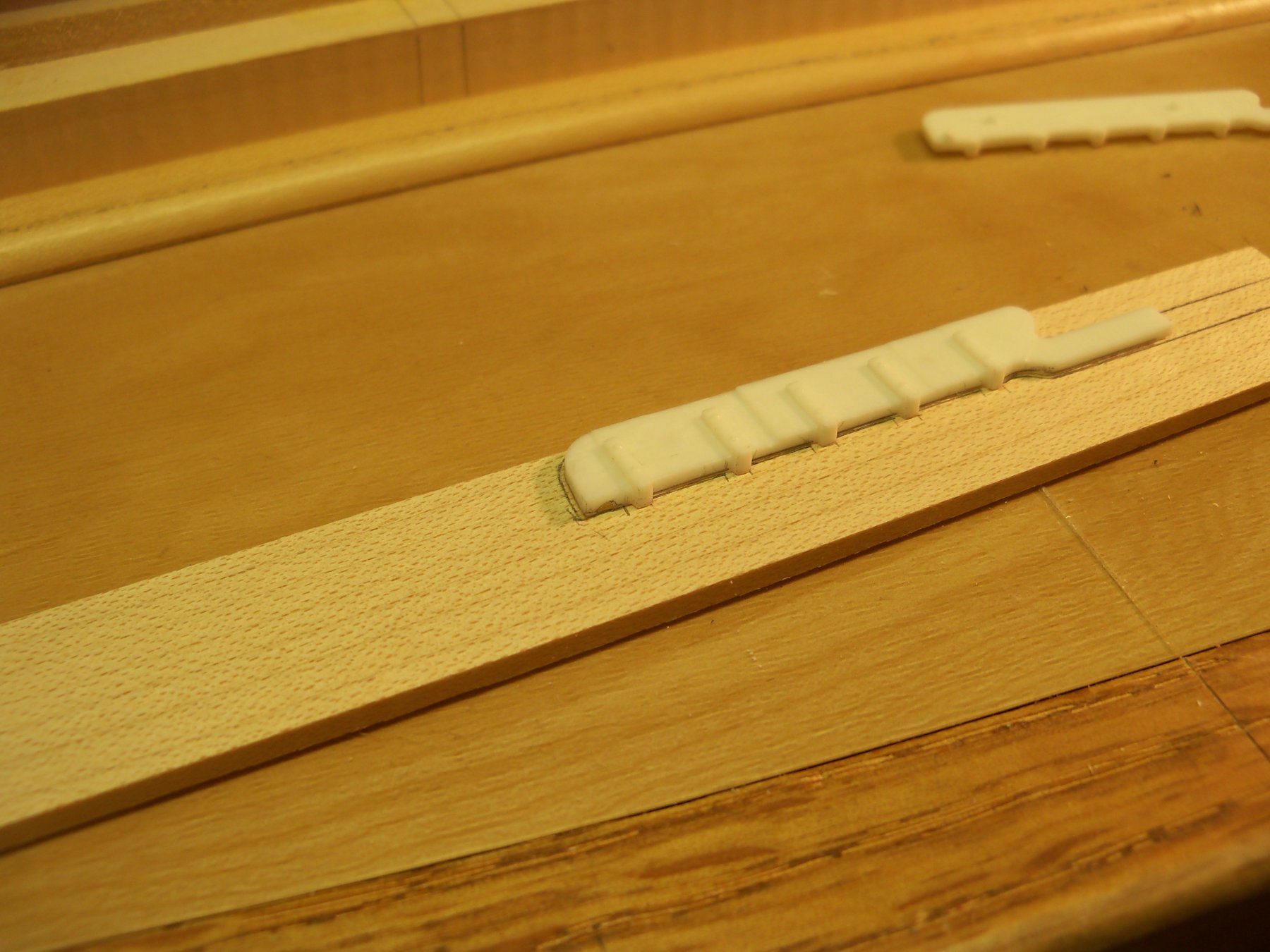
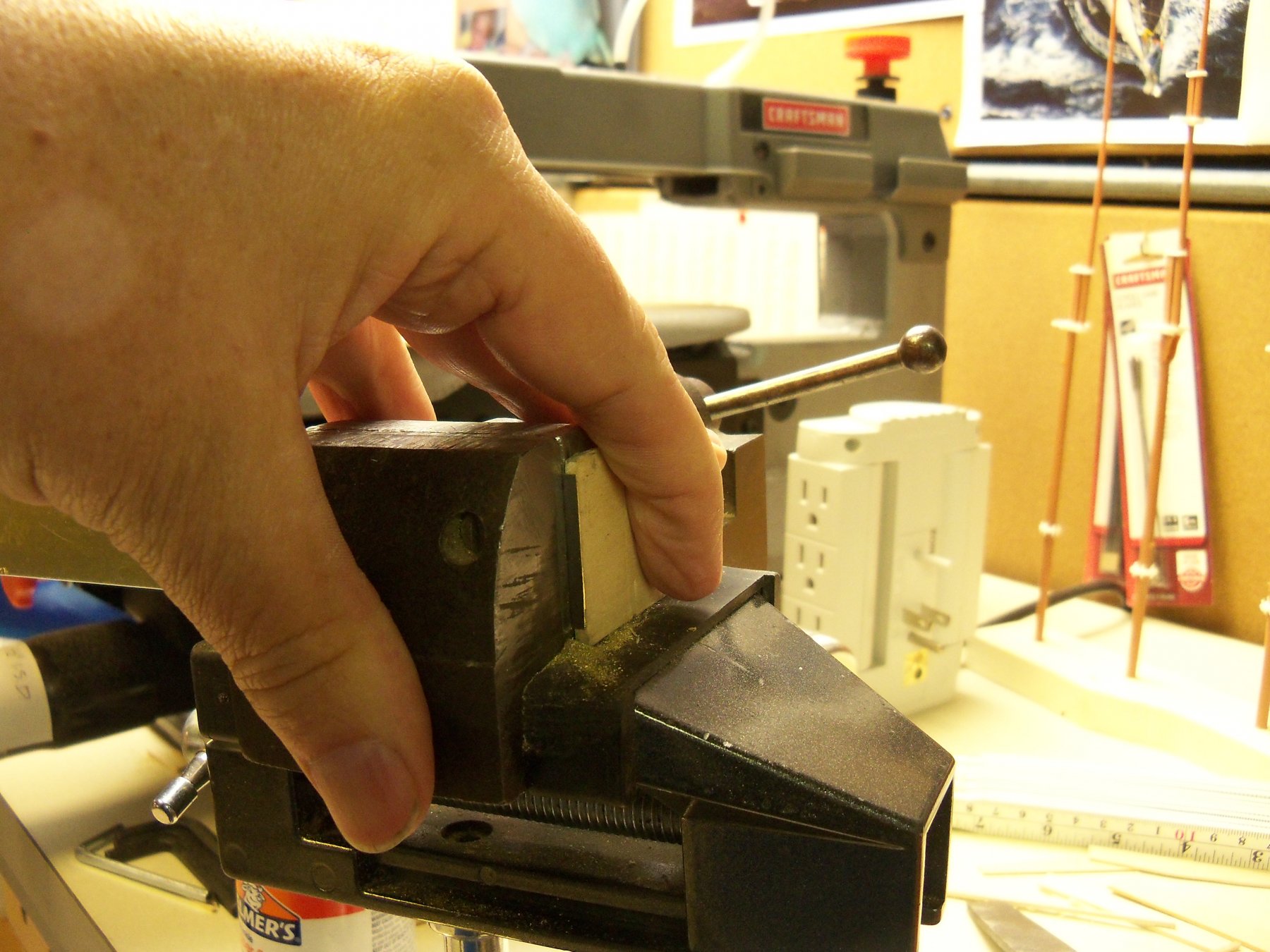
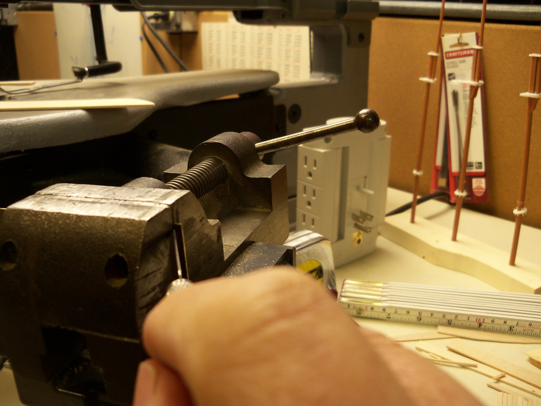
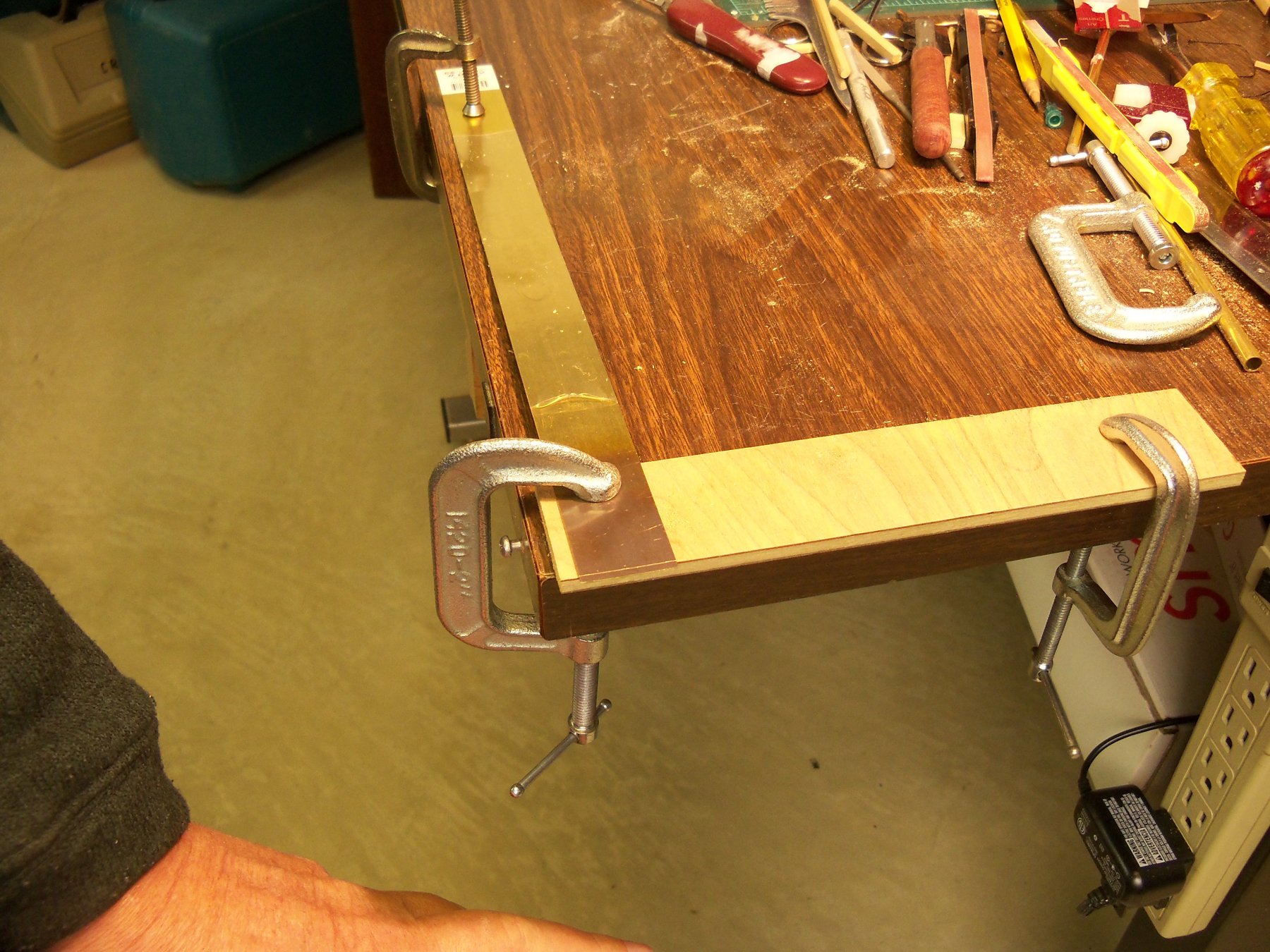
As I said in an earlier post, the plastic rudder provided with the kit was too short to go through the deck to connect with the tiller so I wanted to make a replacement in wood. Taking ½ of the plastic rudder supplied with the kit, I laid it on a strip of maple the thickness of the rudder and traced the outline onto the wood. The pintle locations were also carefully marked (as shown) to assure alignment with the corresponding gudgeons on the ship. A small square was used to mark a perpendicular line across the rudder to make sure their legs could be set square with the edge. The rudder was carefully cut to the overall shape on my scroll saw and then filed and sanded to its final shape including a small square tenon at the top end to fit into a matching mortice in the tiller. Now I needed to make the straps for the pintles and gudgeons from some .016 brass. The end of the brass was heated with my torch till cherry red and set aside to cool. Since the straps needed to be cut to 1/16” wide they were set in my vice by projecting the brass strip through the jaws until they flushed out with a piece of 1/16” scrap and clamped. The brass was then scribed with an exacto blade using the vice jaws as a guide. To set up for the cuts a strip of plywood with a straight edge for a saw support was clamped to the edge of my modeling table. Now the brass strip was clamped into place with the scribed line just the thickness of my jewelers saw blade away from the edge of the plywood. (The clamp on the other end of the brass was set to keep it from twisting during the cut.) I shifted my wheelchair so that the arm holding the saw was parallel to the cut to be made. A stick of wax was used on the blade every so often to lubricate it. Then using a smooth steady stroke with the saw at the angle shown, and using a finger of my other hand to control the chatter, the cut was made. After several cuts, it became an easier operation and I was able to cut each strip in quick succession. When each cut was done, the edge of the remaining brass was squared up and filed smooth in the vice before proceeding onto the next piece. Ten were cut in about an hour this way. Then, having found a photo of the Wanderers’ rudder washed up on shore after she ran aground, I noticed a couple more discrepancies. Contrary to the shape of the rudder on both my plans and the kit, the trailing edge appeared to be a smooth curve rather than straight. There was also no indication in that photo that it was sheathed in copper. Following these discoveries, I have decided to remake the ships rudder as shown in that photo. So, while the rudder itself was to be tossed out, it wasn’t a total waste as the brass strips for the legs of the pintles and gudgeons could still be used since they haven’t been formed or cut to length yet.