MORE HANDBOOKS ARE ON THEIR WAY! We will let you know when they get here.
×


BETAQDAVE
-
Posts
5,383 -
Joined
-
Last visited
Content Type
Profiles
Forums
Gallery
Events
Everything posted by BETAQDAVE
-
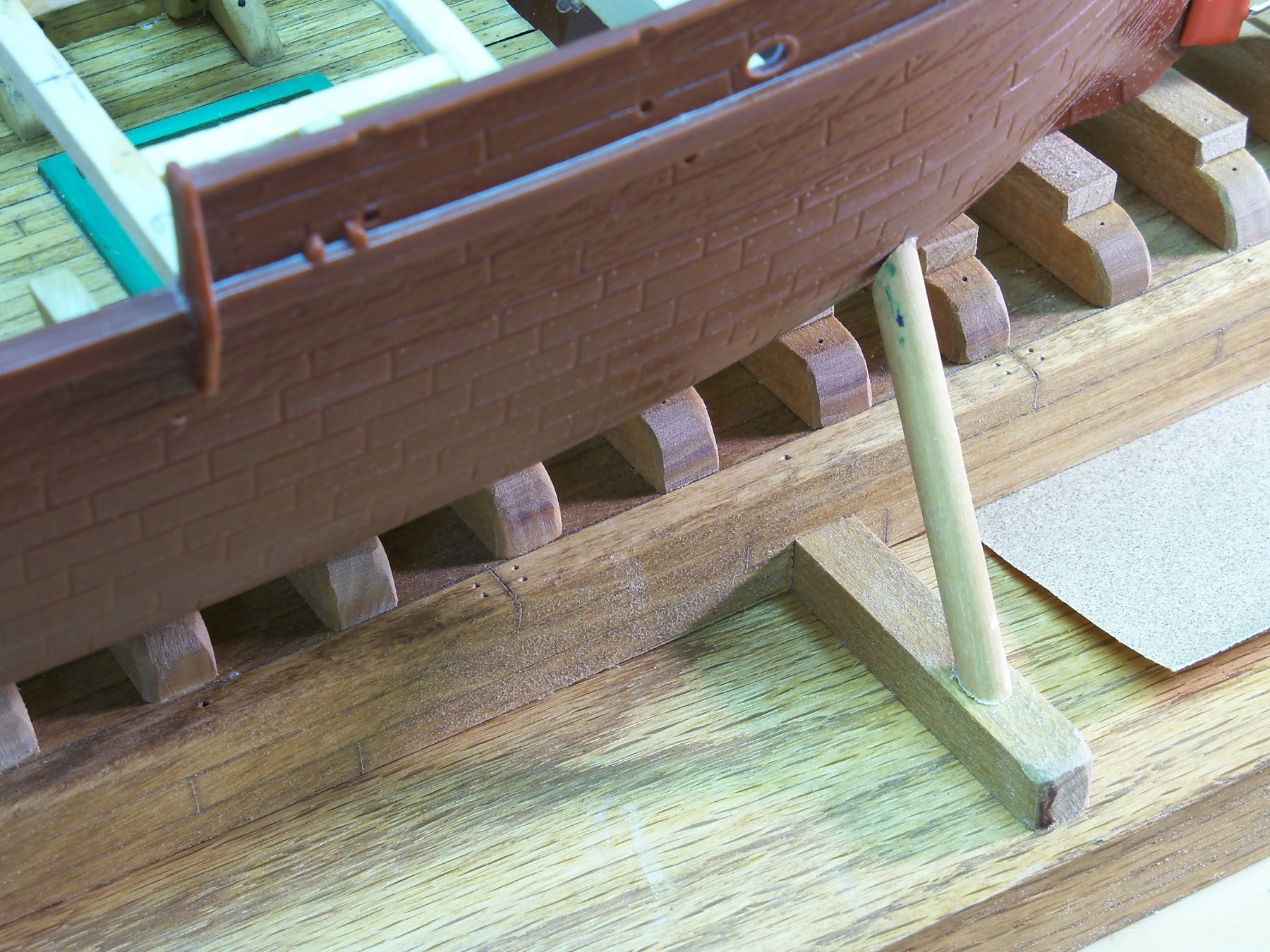
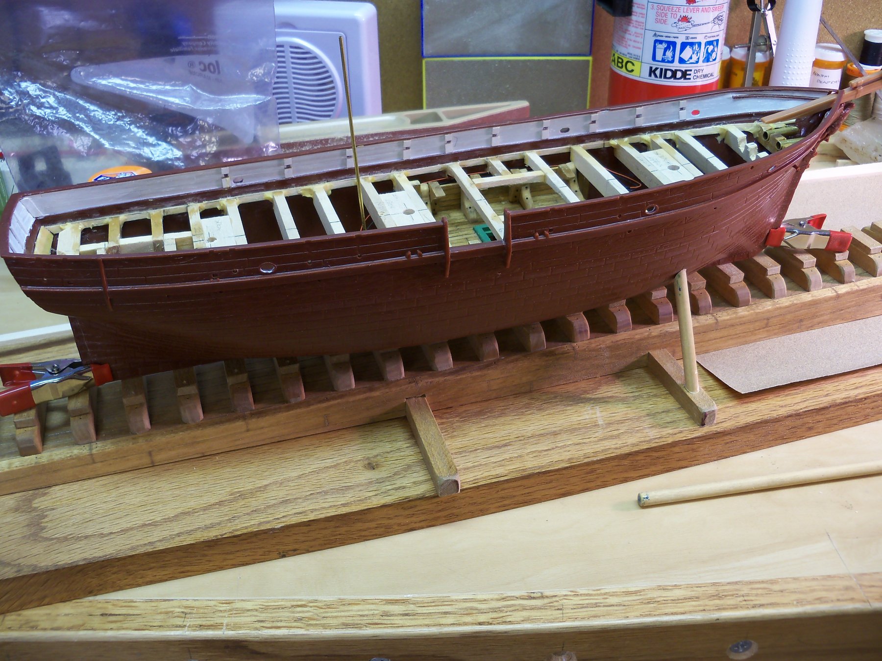
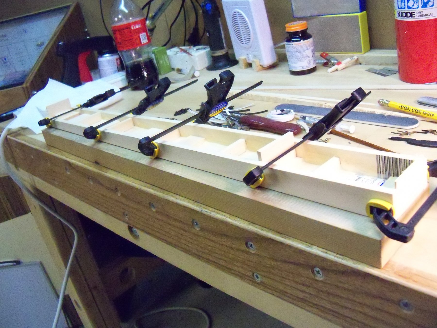
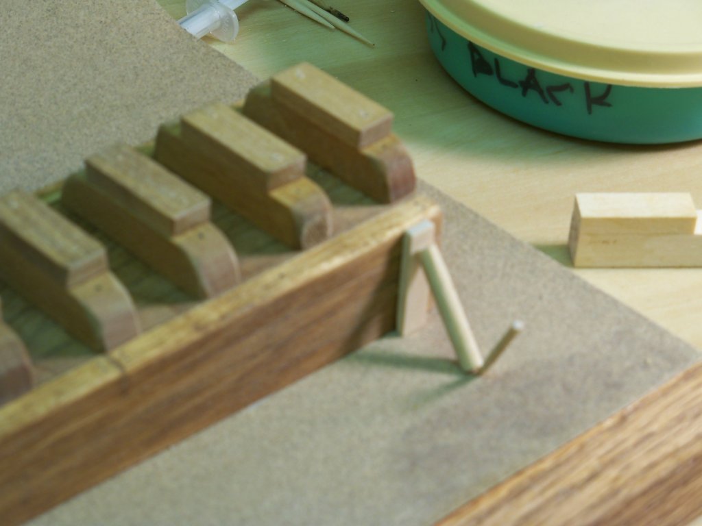
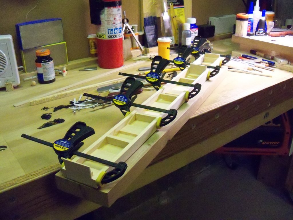
 I finally relocated this photo taken from an old magazine AD I filed in an old misc. ship info folder that I used to put everything nautical in nature into. That was way back when I built my 1/6” scale scratch built whaler Wanderer w/ plans & fittings from A.J. Fisher. That’s also well before I had a computer and became aware that a site like MSW even existed. It did however; give me the inspiration to construct this particular ramp for my display. Coincidentally the model shown in that AD is also an old whaling ship, which while it’s obviously not the Wanderer, the similarities were enough for me. (Judging by certain features including the billet head, false gun ports, seven whaleboats, and the fact that it carried a full ships rig, indicates to me that it may have been the James Arnold, a 346 ton whaler out of New Bedford in 1852.) The next step was to glue all of the keel blocks on the top of the supporting beams. To line them all up evenly I glued the two end blocks first. Then taking a long straight plank butted up to the glued blocks, I tacked that in place temporarily with rubber cement there and a clamp in the center. With the guide now tacked in place it was a simple matter of lining the ends of the keel blocks with it and the edges of the beams and gluing them in place. Here is the ramp shown with the guide in place. Once all of the beams and keel blocks have been attached, I will be adding a little more detail by using some small steel brads to represent the bolts holding them in place. For the retaining wall timbers some brass rod will represent the drift pins normally made from long lengths of iron pipe or rod. Impressions were made in each end of both the keel blocks and the beams with just the point of a pencil. The brads are ¾” long and 18 gauge which measures 1.2 mm, so I had to use a 1.32 mm bit that was the closest size that I had that would be long enough to do the job. The glue would probably be sufficient to hold everything in place, but a little help from the brads wouldn’t hurt either. (I need to get a new collet for my Dremel drill press as their standard sizes can’t hold the bit.) Luckily the chuck on my shop drill press can handle very small bits. The holes were all bored and the brads were given a bath in full strength brass black. Since the holes were very slightly over-sized, a hammer will not be needed to drive them in. A pair of pliers can be employed to set them in place and a nail set can be used to press them home so there will be less chance of wearing off the coating. The next thing to do was to design some braces for the retaining walls. Varying lengths of 3/16” birch dowel will be used for the diagonal braces and beveled on both ends. Lengths of 3/32” x 1/4” basswood will be glued up against the timbers from the ground to the tops of the walls to hold the upper ends of the diagonal braces. The top ends will be shown bolted, and to hold the bottom of the braces, some short lengths of round tooth picks will be used to represent the pegs driven into the ground. Here is a slightly out of focus photo of the typical retaining wall brace. The ground itself will be indicated by some cut sheets of 150 grit sandpaper glued down to the base. Once the sandpaper is glued in place, the setting of the 52 braces can begin. All of the braces are different lengths, so mass production won’t be feasible here. It looks like it will be a lot of cut and fit for each one with diagonal holes drilled in the base for the pegs. The actual hull braces were formed with some hefty sized timbers which in this case will be ¼” birch dowel to represent the scale 24” dia. peeled timbers. These will have their top ends beveled to match the hull of the ship and the bottom to the 3/8” x 3/8” grade level long cross timbers. Here is a close-up view of a hull brace temporarily set in position. Here the ship is propped in place and located on the ramp to measure and cut the hull braces and to also align the holes through the keel and keel block for the light wiring that will have the batteries and the switch routed into the bottom of the base board. (That’s that brass rod sticking out in the photo.) Two additional holes also need to be located and drilled through the bottom of the ramp into the hull of the ship for a pair of mounting bolts that will go into some nuts set into wood blocks glued inside the hull. Between painting the copper portion of the hull, (not to mention constructing my spray booth) finishing the pintels and gudgeons to mount the rudder, finishing the ramp details, and mounting the ship onto the base, it may be quite some time before my next ship posting. (I plan on posting the spray booth construction on the Modeling Tools And Equipment section on the MSW site.)
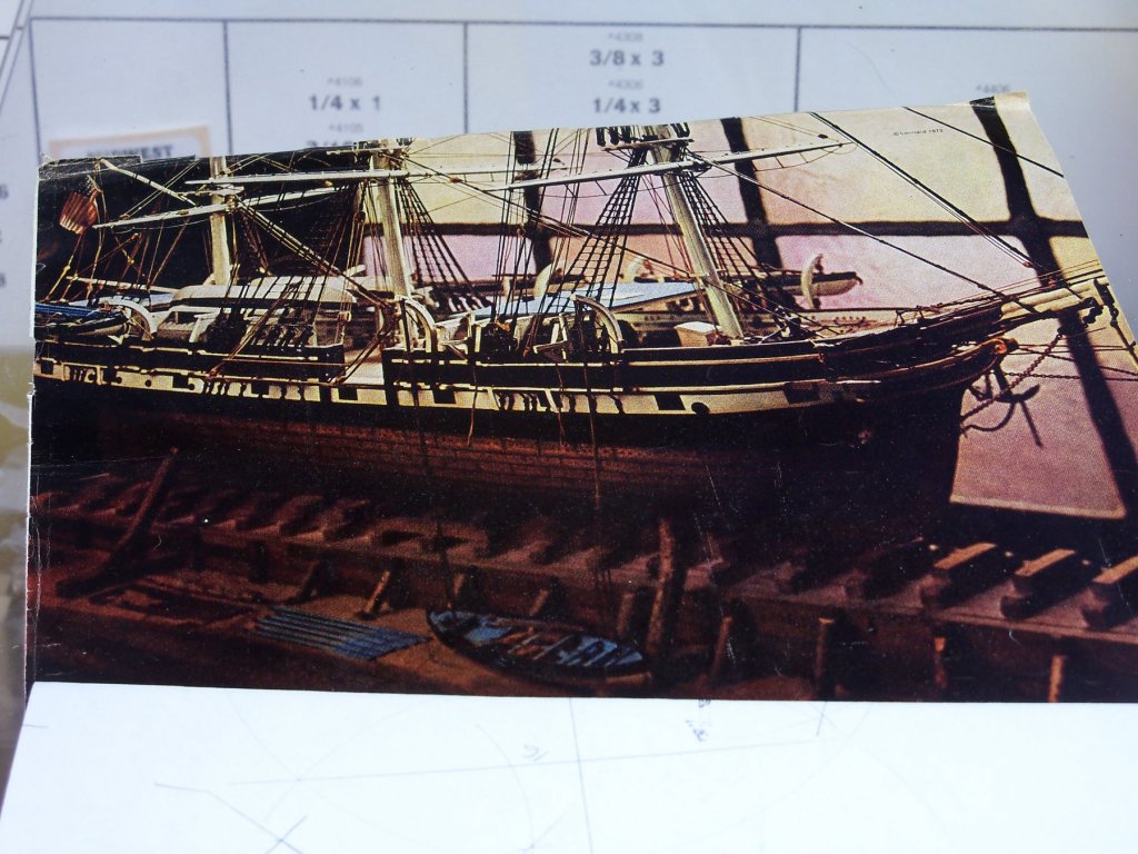


-
Actually Mark, if you look at the first photo in post #186, I think you can see a little better that the line in question is actually behind the rudder and the only connection to the rudder is via the hanging chains.
-
Well Kortes, your work is quite a step above what most of us here can produce and it can make a lot of us feel somewhat inadequate. On the other hand, work such as yours can only inspire us to try to do better. I feel you about your desire to remake portions of your project that you are unhappy with as I find myself doing the same thing with my Phantom. I have remade some of the ships deck houses several times, until I was happy with the results. While there exists the popular notion with some people to “just get er done” as they say, I don’t subscribe to that school of thought at all. As I often said at work, “Why does it seem that there is never enough time to get it done right, but always time to do it over?”
- 306 replies
-
- 2
-

-
- schooner
- la jacinthe
- (and 1 more)
-
I wasn't around here at the time of the old forum, so I haven't seen your build log before. Other than some slightly irregular decking seams, I can't say that I can detect any obvious errors that you mentioned. On the contrary, your photos of the transom and the ships boat show that you have some areas that are very well done. I haven't seen many ships modeled with clinker style planking, as it appears to be a rather hard detail to master, but again, it looks like you did a credible job of that also. Your sails are also shown to good effect. Overall, (despite some errors that you claim to have made that are not readily visible to me), your ship looks quite well done.
-
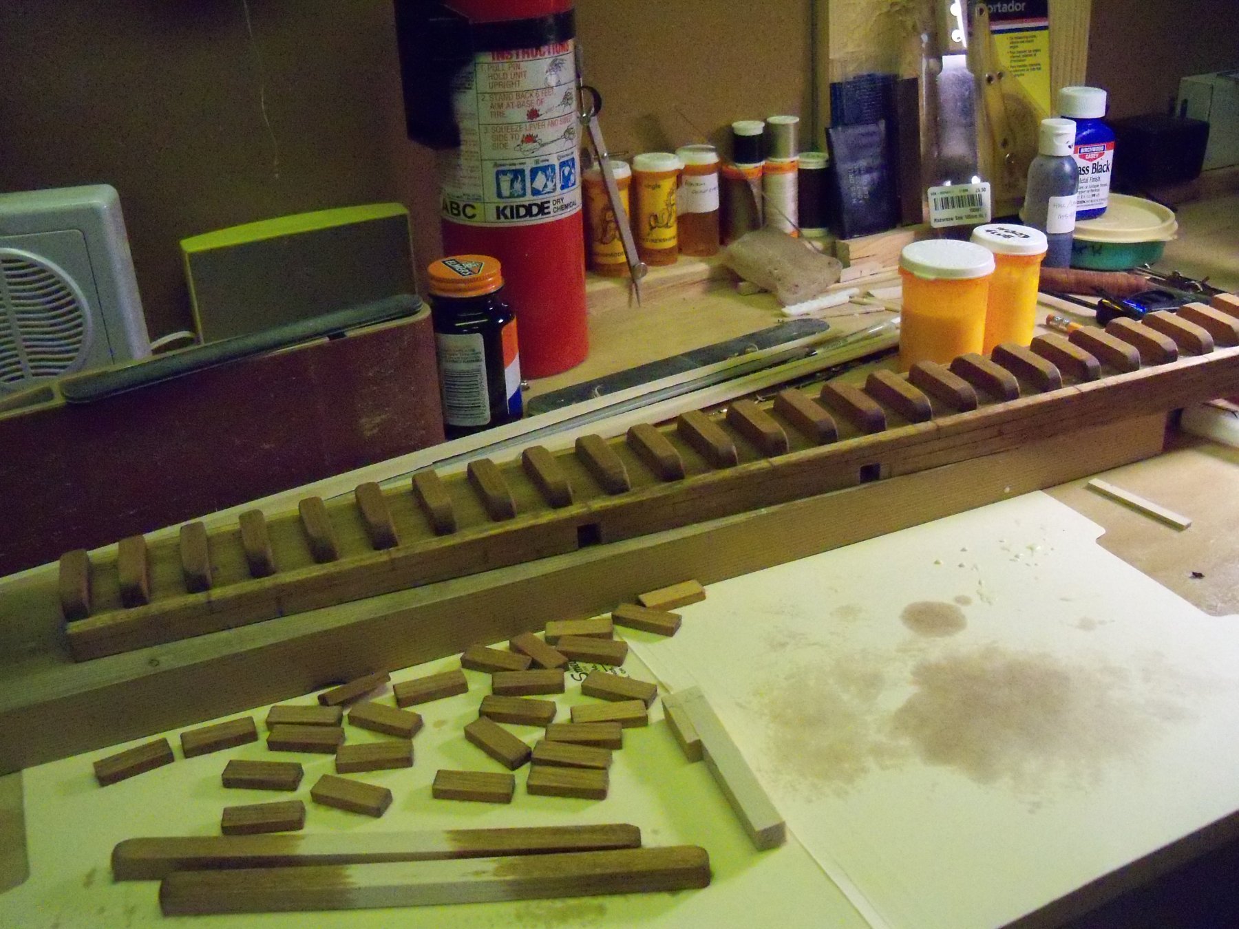
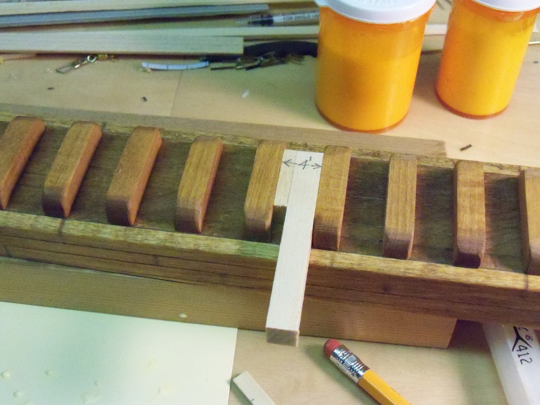
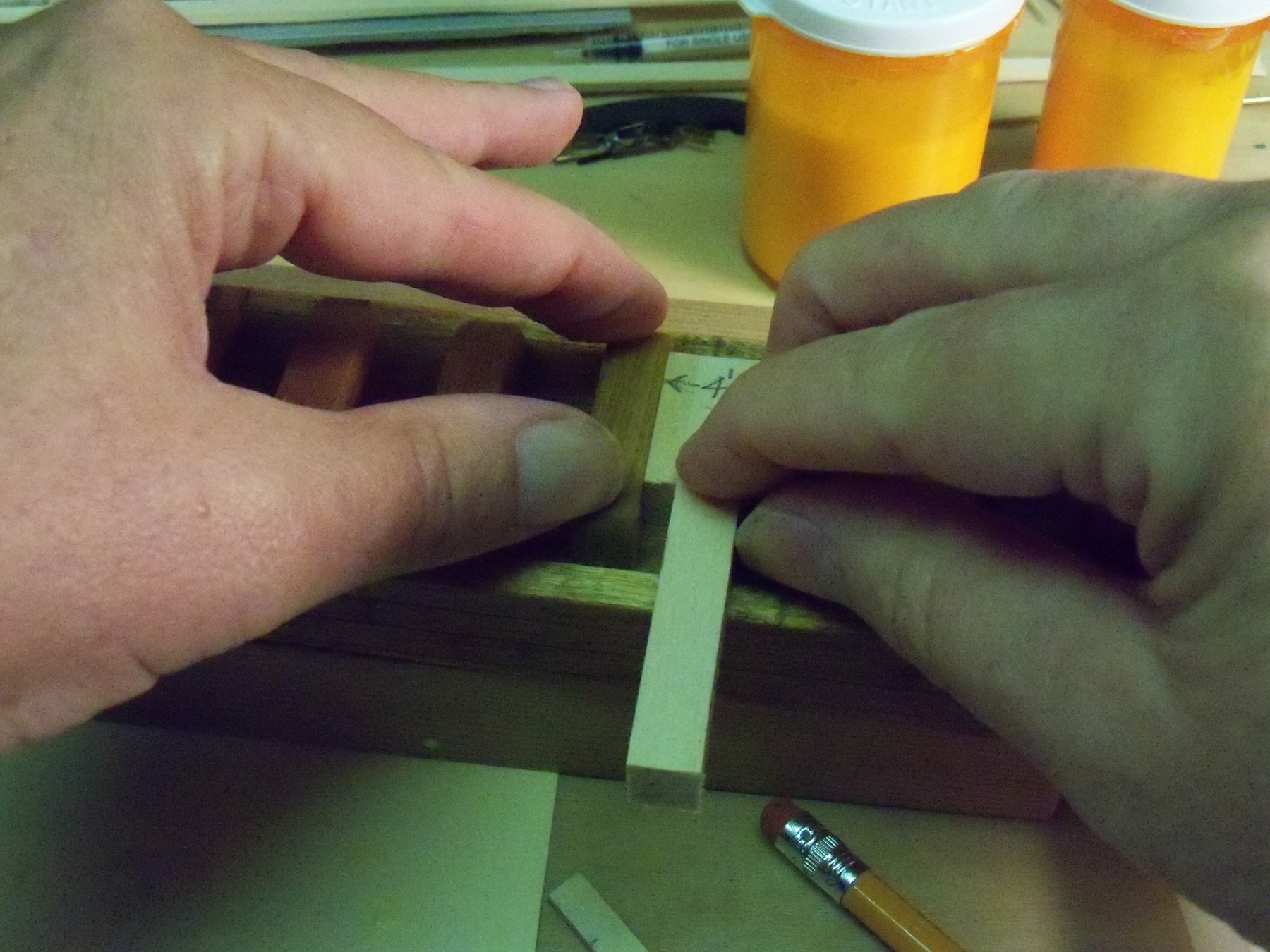
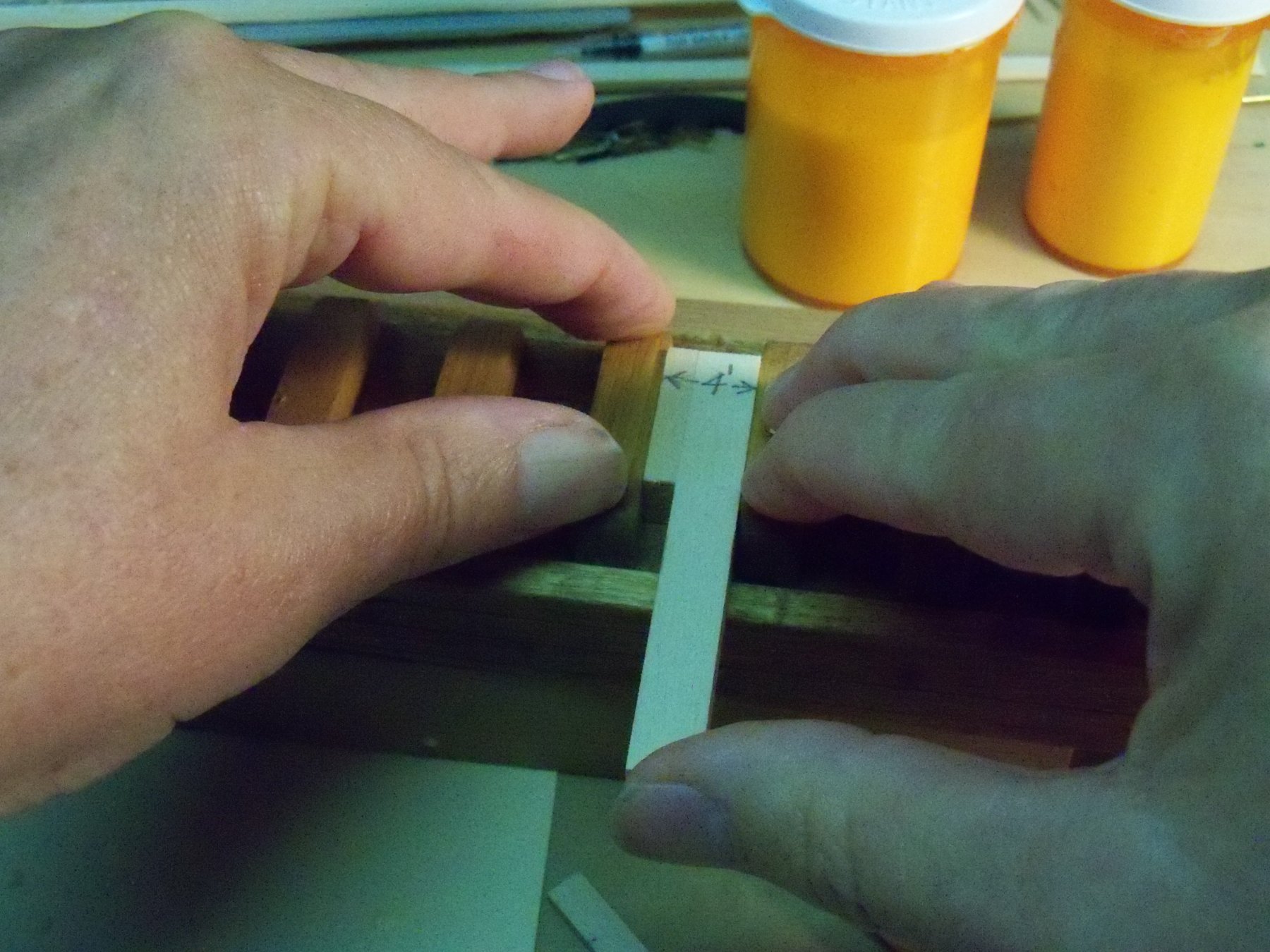
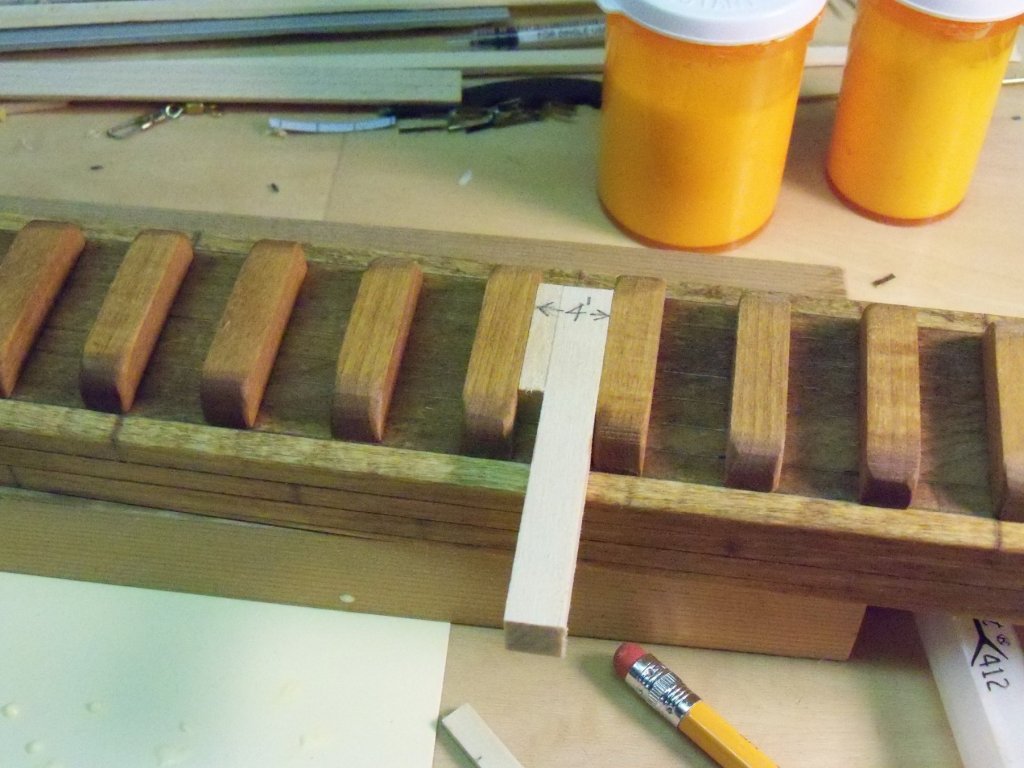
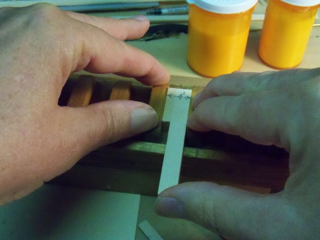
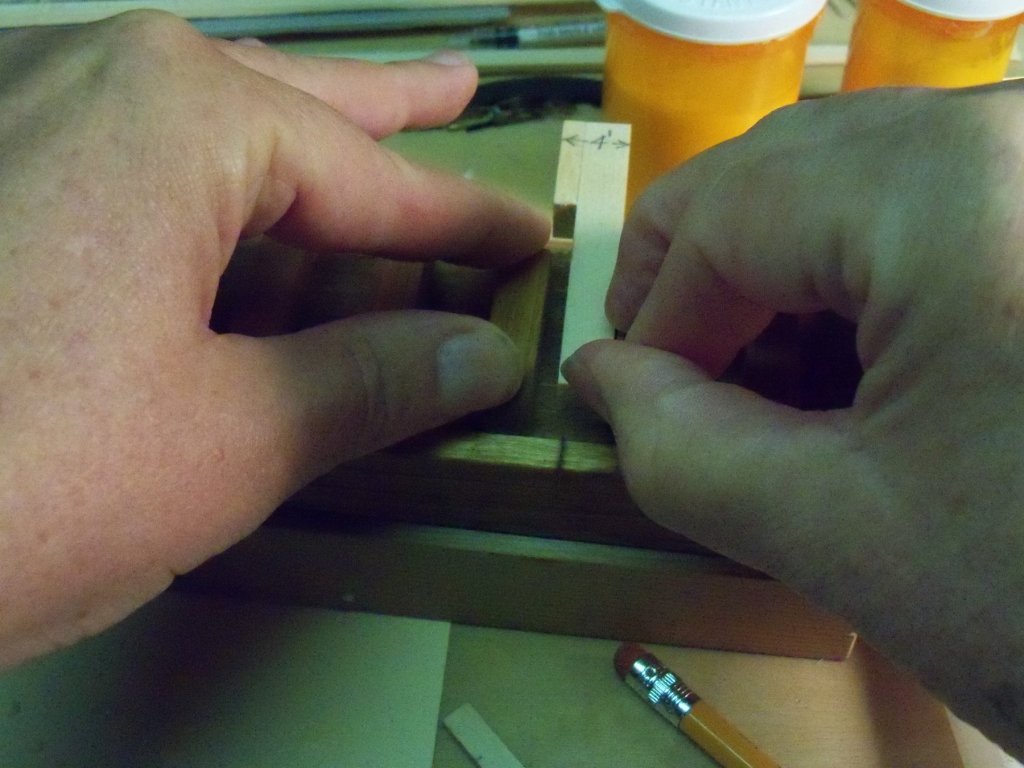
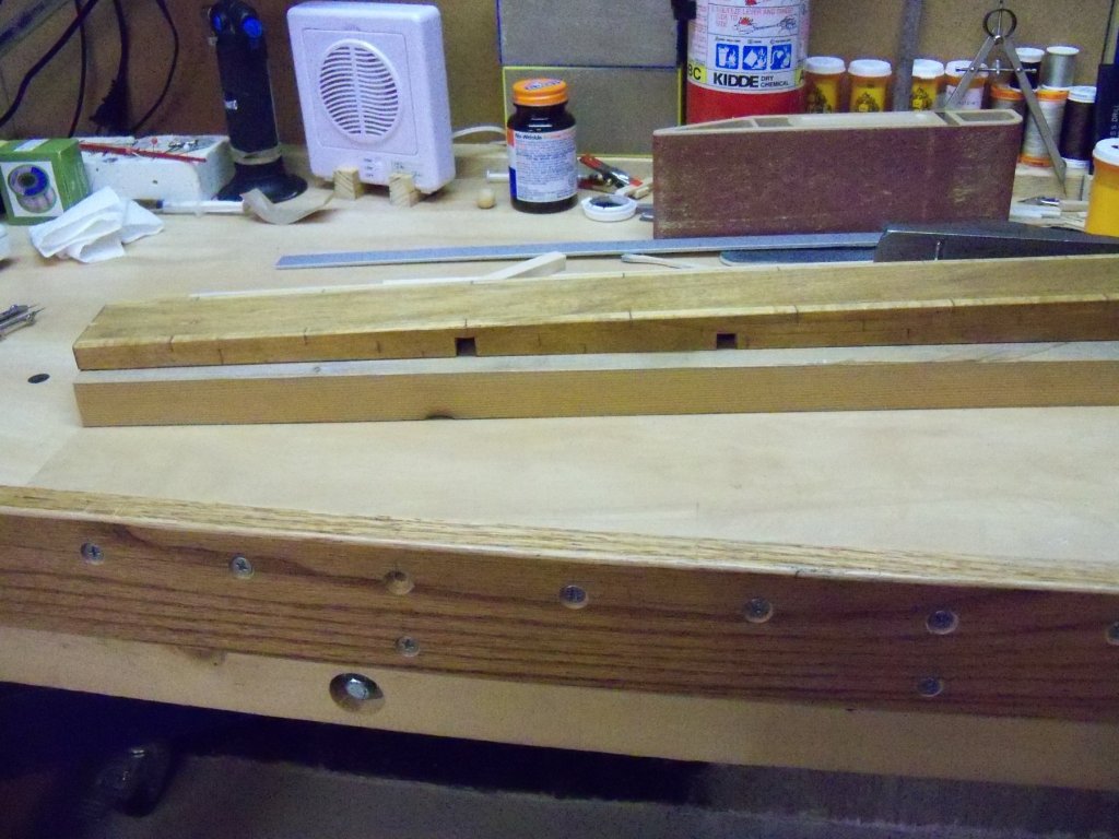
This log entry will catch me up with the actual construction before I get back to it tomorrow. Sometimes a medical timeout can work to your advantage. Since I was unable to actually work on the ship for a while, I could still use the computer to do the log. (No strain, no pain.) The cut components for the ramp had been stained and dried so all of the keel block support beams were glued down with wood glue and the current status of the ramp is as shown below. Rather than glue them down and waste time waiting for the glue to grab each beam, I made up this spacing tool to speed things up a bit. As you can see it’s just one short piece glued to a longer one that has a total width of four feet to scale. Here is a short review of the process. Holding down the beam just glued down with my thumb and three fingers of my right hand, one other finger was used to hold the spacer in place. The next beam in line had glue applied and was held in place with my left hand as shown. Now with my right thumb, I slide the spacer forward until it releases. All the time through this procedure, pressure needs to be carefully maintained on the beams to keep them from shifting out of position until the spacer is released. Then it’s on to the following beam. I placed all 26 of the beams in about 30 minutes, so my system worked just as planned. (Imagine that!)


-
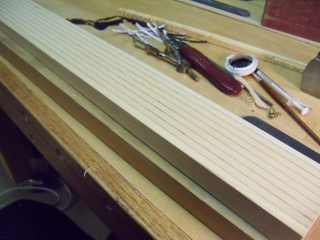
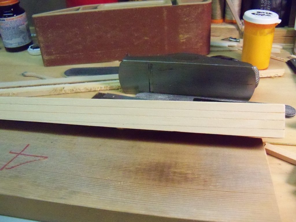
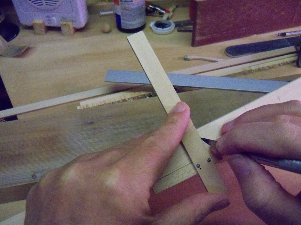
Now that the ramp assembly was dried, I tuned it upside down and trimmed all of the excess projections off with a plane and sandpaper. On the top of the ramp I took a No. 2 pencil and ran it along the scribed lines on the top planking to make them stand out better. I did the same to the joint between the planks and the retaining walls. This is the result here. The sides of the retaining wall also needed some indication of individual timbers, so using a long metal straight edge three joints were drawn parallel to the top of the ramp on both sides. That same long metal straight edge was now aligned with the marked line and clamped to the sides. To ensure that the resulting scribed lines were very pronounced and straight, my small back saw was slid back and forth with a light amount of pressure along the edge for about a dozen strokes. Making sure that the timbers appeared to be individual lengths, I made some tic marks on the individual timbers at a maximum scale length of 24 feet with joints offset by 4-6 feet from layer to layer. Going back to my scrap pile, I made a small wooden square as shown below. The square was set perpendicular to the top edge of the ramp and using a No. 2 blade those joints were scribed in. Setting the ramp on the building board and placing the ship where it would be sitting on it, I located the position of the two hull braces. I marked the two notches for those 3/8” x 3/8” grade level long cross timbers on one side. The ramp was placed upside down in my carpenters vice and using my back saw the saw kerfs of the notches were cut down to the top edge of the marks. Using my wood square, those kerf lines were extended over to the opposite side of the ramp. Setting my back saw blade into the kerf on the near side and lining it up with the new marks on the opposite side, I had somewhat of a miter saw setup that ensured the kerfs would line up across from each other. A chisel and scalpel were now used to clean out the waste from all of the notches. The entire ramp was given two heavy coats of Minwax light oak to give it the appearance of weathered oak timber construction and set aside to dry overnight with it as it stands now below.
-
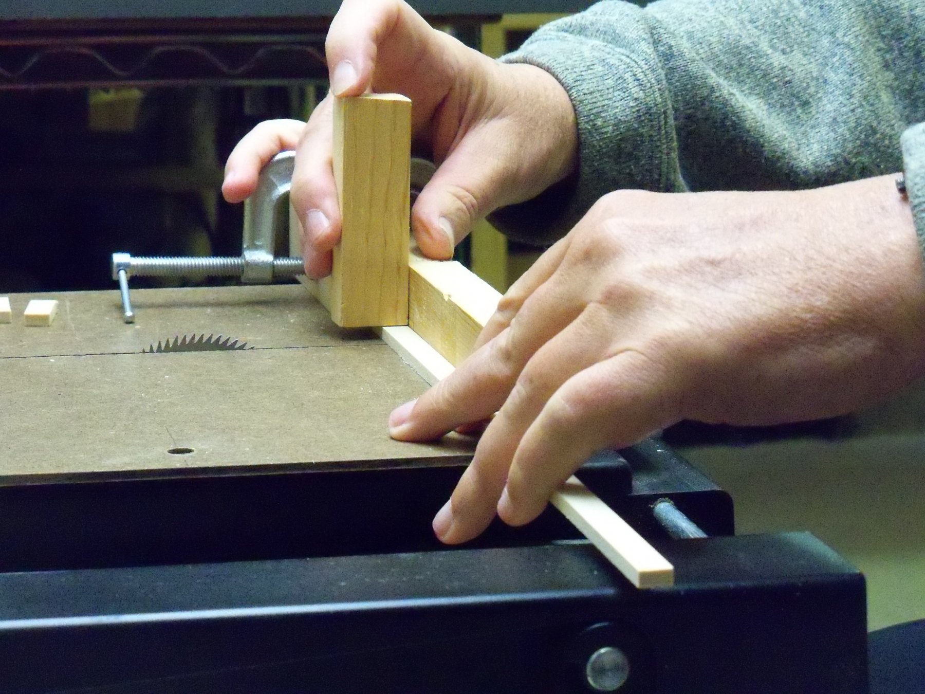
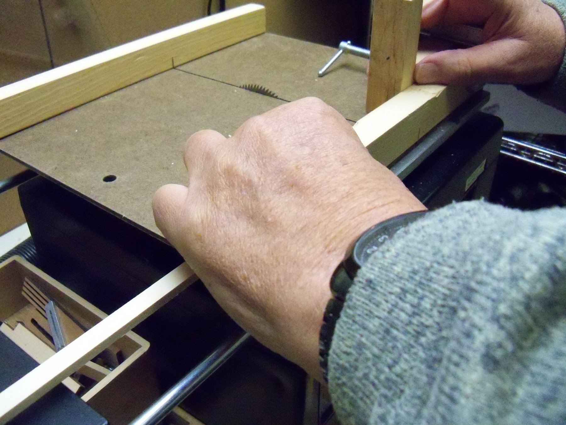
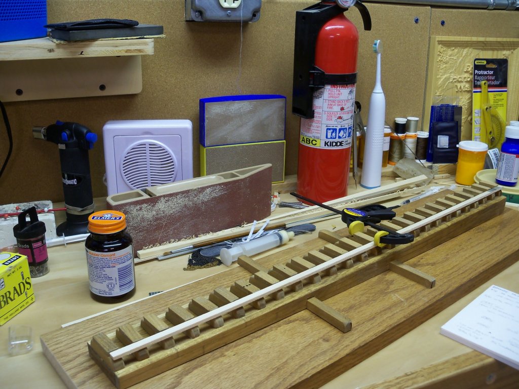
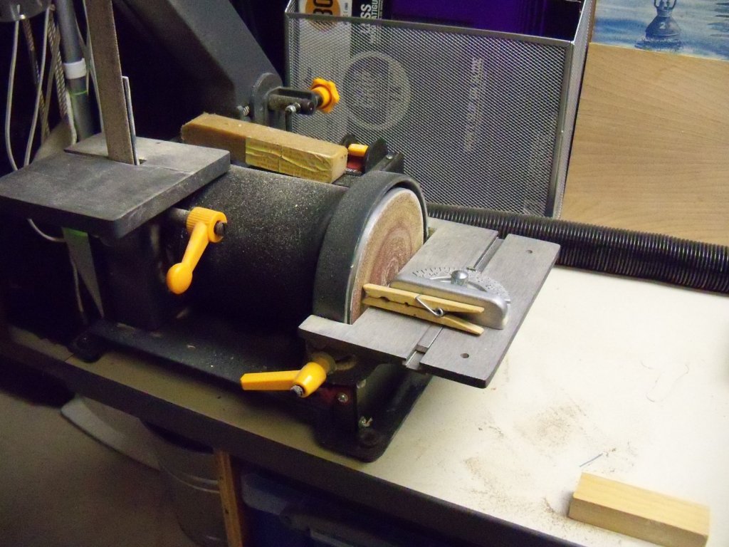
Just before my little internal misfortune, I had decided to do a few things before continuing to work on the pintles and gudgeons. Since the hull coppering needs to be painted before installing the rudder fittings, I would be doing that, but I also needed to construct the model stand to keep from damaging the paint job once that is done. I have decided to support the ship on launching ways, so I did a lot of searching for ideas on that. Having finally come up with a combination of various systems that I came across to accent the model display, I started construction with my excess stock of basswood. A long tapered ramp was the first phase to work on. The design used was a pair of timber retaining walls filled with earth or gravel fill capped with timber planks and heavily braced. (Of course my ramp would not be filled, but rather hollowed out for installing the light switch and battery.) Keel blocks were set on timber beams spanning the timber planks. Two long cross timbers were run on grade through the lowest retaining wall timbers and projected well beyond the faces of the wall. A pair of heavy diagonal braces was anchored on top of it to brace the hull of the ship. The first step was to make the side retaining walls by taking two 24” lengths of ¼” x 1” basswood and marking the taper from ½” at the lower end to 1” at the upper. The taper was then cut just short of the drawn line with my band saw and then trimmed to the line with a small block plane. Now taking a 24” long sheet of 1/16” x 3” basswood that was prescribed with ¼” wide planks, I ripped it down to 1 3/4” for the timber planking on the top of the ramp. A homemade sliding cutoff table was put on my Micro Mark table saw with a stop clamped to it for cutting 3/8” x 3/8” basswood strips into 26-1 ¾” lengths for the timber beams that would span the timber planks on the top of the ramp and provide support for the keel blocks. This photo below shows the setup for cutting all of the various timbers to length, with the stop clamped to the fence. My SOP for short cutoffs is shown with my right hand holding a block to hold down the cut off end (to spare the fingers) and the left hand (well away from the blade) is shown holding the other end of the timber to be cut. The table is pushed well beyond the blade before the saw is turned off and the two pieces are removed. Pulling the table back, the timber is advanced to the stop to repeat the process. Once those beams were cut, they went over to my small belt sander to round off the tops of their ends. Looks like I need to adjust my dust pick up fitting, as even with my dust mask on and the room fan running, there was quite a bit of dust on the loose during this operation. Even though the ends were now rounded over, some hand sanding was still required to ease the corners and sand the surfaces. Now the cutoff table was employed once again to cut 26- 1” long pieces of 3/16” x 3/8” basswood for the keel blocks, which of course also needed some finish hand sanding. While the cutoff table was still in place I cut some scrap basswood into several 1 3/4” long pieces for blocking for the interior of the ramp. With the majority of the parts cut, I moved onto the actual construction of the ramp. The 1/16” basswood sheet was placed with the scribed side face down on the building board. The two tapered retaining wall sides were butted up to both edges of the sheet and several of the pieces of blocking were set onto the backside of the sheet. Two small bar clamps were put into place to hold the assembly in position for alignment. Once satisfied, I tightened the clamps and placed the remaining blocking in place. Three more clamps were placed and the ends were filled with some 1/16” planking sheets. Once more, the alignment was checked and adjusted. The assembly now appeared as shown below. Wood glue was spread along all inside edges and the assembly was set aside to dry overnight.


-
Vanda-Lay Industries
BETAQDAVE replied to BETAQDAVE's topic in Modeling tools and Workshop Equipment
Thanks Gary. (I'm afraid that didn't even think of using that search function. ) I went through all three pages and found that with all the good comments in there, I think I'm sold on getting one. Will probably get their optional accessory table to go with it. I will try it out and give a review myself of how well it works. -
Does anyone here have any experience with this company? They offer heavy aluminum tool supports to convert your rotary tool into a micro mill; lathe; drill press; or router/shaper table. I am mainly interested in their drill press. Their site makes this claim: DRILL PRESS PLUS GIVES YOU STABILITY WITH THE DREMEL TOOL. MACHINED FROM SOLID ALUMINUM, AND WATER HARDENED 1/2” DRILL RODS. THIS IS A TOOL THAT WILL NOT WEAR OUT, AND WILL ALWAYS DRILL SMALL HOLES ACCURATELY. Looking at the illustrations that are shown, I would tend to believe those claims. It appears to be quite solidly constructed and has the added benefit of being American made. I have the drill press accessory made by DREMEL, but it is not really stable enough to drill small holes without breaking the micro size drill bits. Their price at $140 + S & H also seems reasonable, but I haven't seen any reviews to base my opinion on, so I am fishing here for some input.
-
Question about table saw technique
BETAQDAVE replied to jdbondy's topic in Modeling tools and Workshop Equipment
Personally, I have found that most of the problems with cutting thicker boards (or tougher wood) can be solved by just slowing the rate of feed. It allows more teeth to make the same cut and a smaller bite of wood to cut through for each tooth. (not to mention usually a smoother cut) As they say: let the tool do the work. Forcing the board through the blade wont make it cut any faster. That reminds me of when my Father-in-law was helping me to install the wood siding on our current home. He seemed to think that the saw was at fault when it kept bogging down and stalled as he pushed the saw as hard as he could. But, even though he watched me when I would cut the same board much faster by letting the saw do the work, he would never admit it and continued to force the saw every time. My wife just told me to let it go as he was just a stubborn old German farmer (her words) who would only do it his way anyhow. I agreed with her assessment, but just the same I made sure that I did most of the cutting rather than let him burn out my saw. -
I see alot of micro sized bits being marketed for PCB or CNC that have a short length of bit with 1/8" shaft and a colored plastic collar. Are these any good for drilling metal or just for soft materials like wood or plastic? For one thing most are listed as manufactured in China, so I'm a little skeptical of the quality.
-
Shop Safety and Oops Repairs
BETAQDAVE replied to BETAQDAVE's topic in Metal Work, Soldering and Metal Fittings
That was the first time that I used on metal and it was an old piece of galvanized tin flashing shingle. I haven't tried it out on any other metal as of yet, but I will experiment a little more soon. However with my limited gripping strength, I'm not sure that my results will give you an accurate picture of how it will perform for someone with a more normal grip. I think that if I need to cut metal again I will use a clamp or vice to hold it and spare the rest of my digits! -
Shop Safety and Oops Repairs
BETAQDAVE replied to BETAQDAVE's topic in Metal Work, Soldering and Metal Fittings
Looks like a chain mail glove there. No doubt cutting or stabbing ones self would be difficult, however I'll bet they are quite heavy and really hamper your dexterity which in itself could lead to other injuries. Seems like sometimes you're up a creek one way or the other. I changed the dressing today and found that it's healing quite nicely, the combination of the special band aids and CA really sealed it up quite well. (By the way, those band aids are not only coated with an anti-bacterial coating on the inside, but the band aid itself is made with some kind of gel between layers which really soothes and protects the wound.) -
Shop Safety and Oops Repairs
BETAQDAVE replied to BETAQDAVE's topic in Metal Work, Soldering and Metal Fittings
Speaking of which, I would like to take this opportunity to thank my middle finger for always sticking up for me when I need it! -
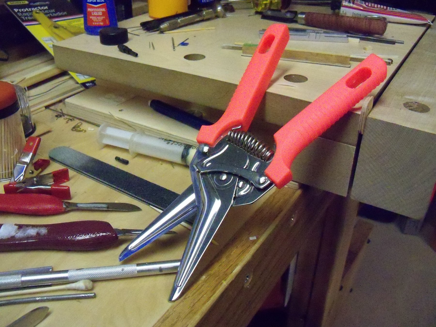
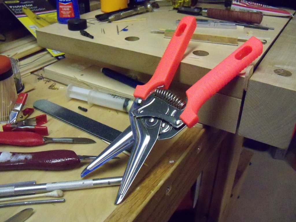
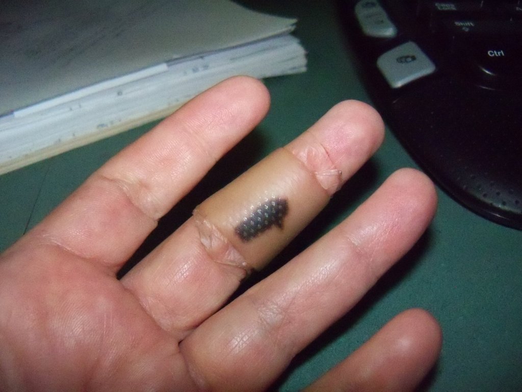
Having had training in safety and first aid in College and the Army, I recently had an oops in my shop where I had to make use of that training on myself. When cutting sheet metal, I was always cautious with handling the metal itself, but apparently not so much with handling the cutter. Quite by accident, I have just recently discovered a new way to skin a cat. (Or was that a new way to skin myself?) I found, much to my dismay, that the new cutter I recently acquired (That was touted as capable of cutting just about anything, especially those obnoxious plastic blister packs that everything sold seems to be enclosed in.) shown below was also quite adapt at cutting flesh! The blades are a tough alloy that is extremely sharp with a finely serrated edge that won’t slip while cutting. They are spring loaded which makes them easy to handle. (Maybe a little too easy?) Well anyways, while carefully holding the sheet metal in my left hand and the cutter in my right, I was intently concentrating on following my marked cut line. As I got close to the end of my cut, I seem to have lost track of exactly where my fingers on my left hand were. You guessed it!! They were lined up with the cut as I apparently was trying to grip both the sheet and the cut off. While I was successful in holding both, I suddenly realized that the tip of the cutter cut more than just the metal. Don’t ask how I did it, but I had managed to cleanly cut a good sized chunk of skin lengthwise off of the inside of my middle finger. Somehow, apparently with surgical precision, I cut completely through the skin without damaging the muscles or tendons. Surprisingly enough, there was not much pain and very little bleeding. So at first I really didn’t think that it was too bad until I held up my hand and the flap of skin fell open. Having a first aid kit in the shop really paid off though as I was able to take care of it quickly. Once I cleaned it out with water and hydrogen peroxide, I managed to roll the flap closed and tacked back in place with a few dabs of CA adhesive to hopefully save the skin. Covering the wound with an antibacterial coated band aid made specifically for finger injuries that came in the kit, all seems well. (see below) Since I had recently gotten a tetanus booster, I will just watch it closely for a while. As they say, figure out what went wrong, and try not to repeat the same mistake again. Although I did learn that thanks to some foresight on my part by having a first aid kit so handy to allow some quick repairs, and keeping my tetanus shots up to date I saved myself a trip to the clinic. Hopefully the skin will reattach itself in place as that many layers of skin take quite a long time to grow back and spare myself the pain of having raw tissue exposed until it does. I once had my big toe nail torn off that exposed the raw tissue below that issued me a painfully clear warning to not do that again any time soon! So take heed of my warning here and make sure that you keep a first aid kit handy and know a little bit about first aid so you know just what to do with it!!
- 15 replies
-
- 10
-
-
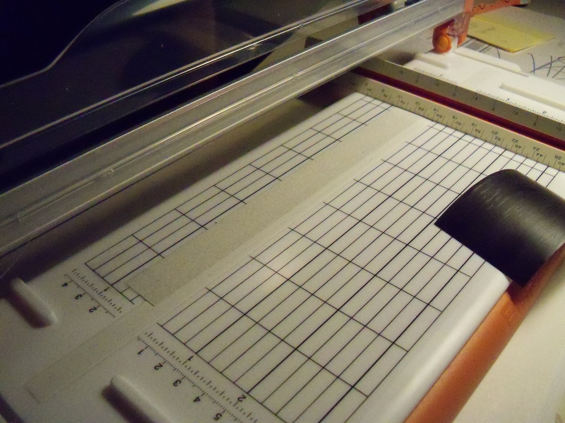
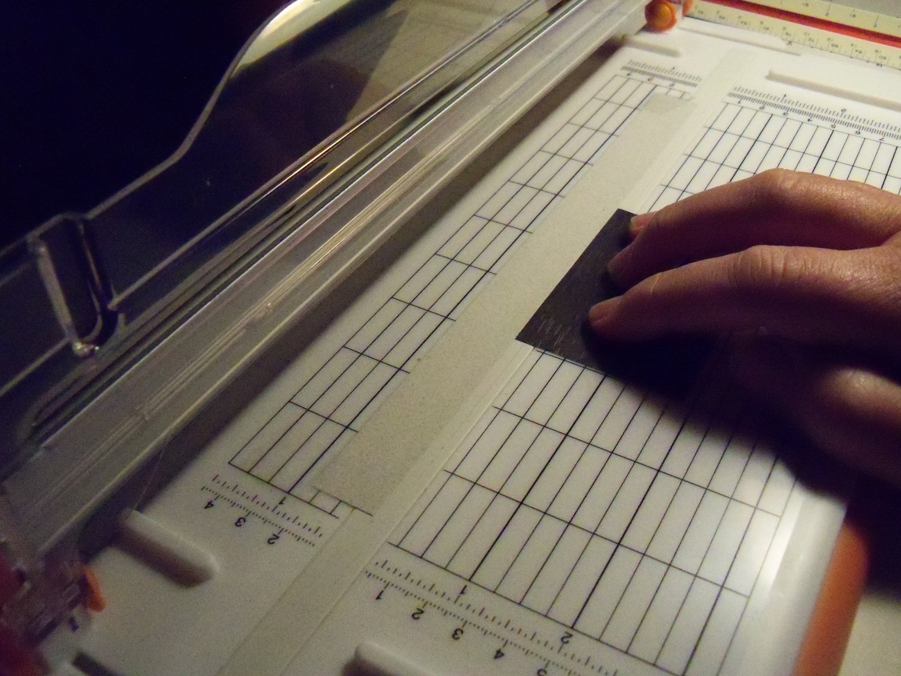
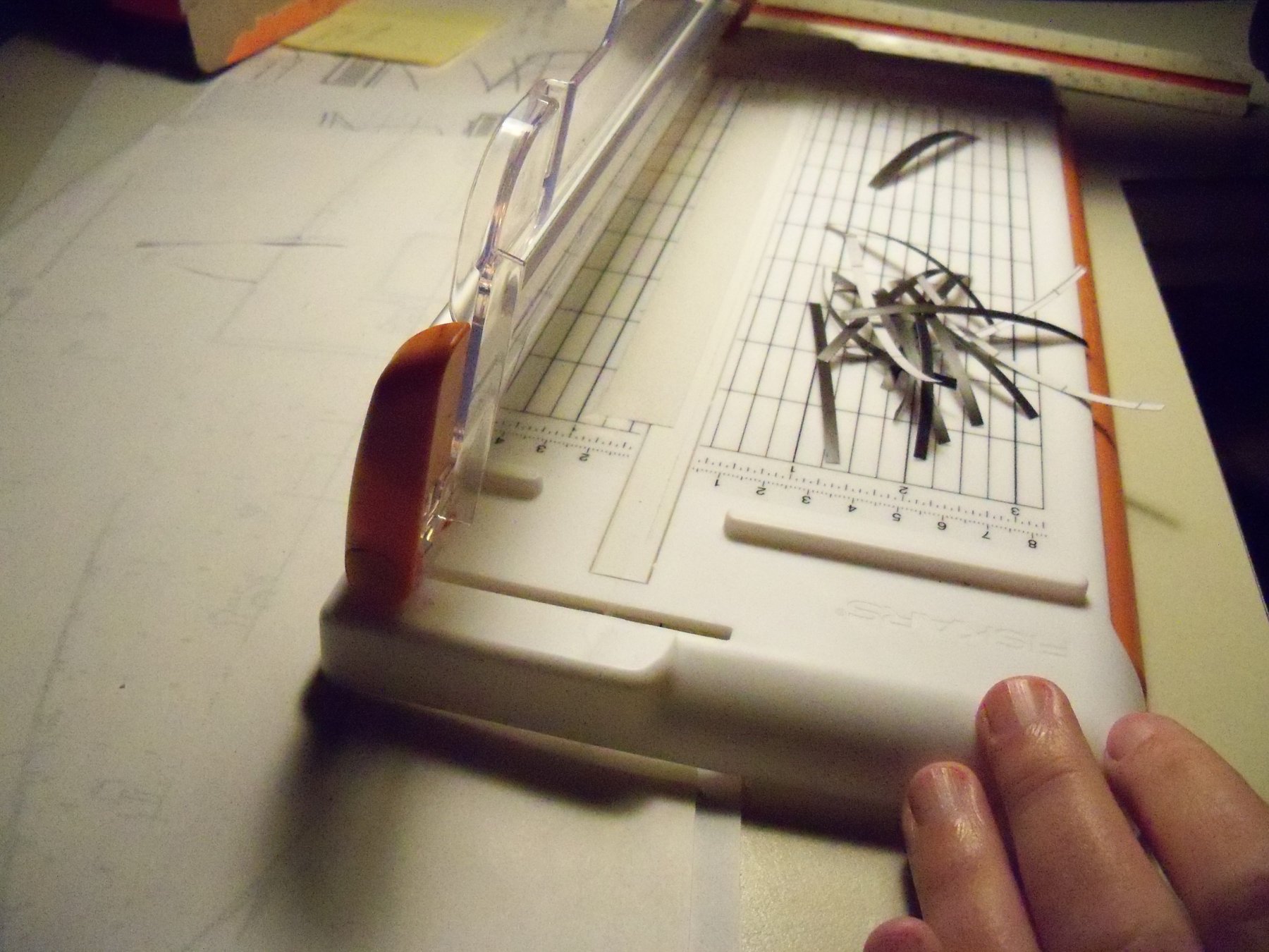
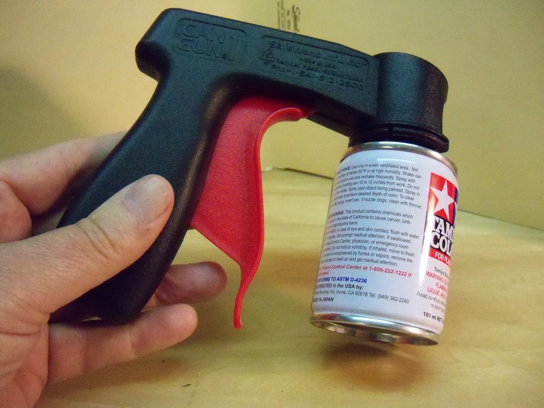
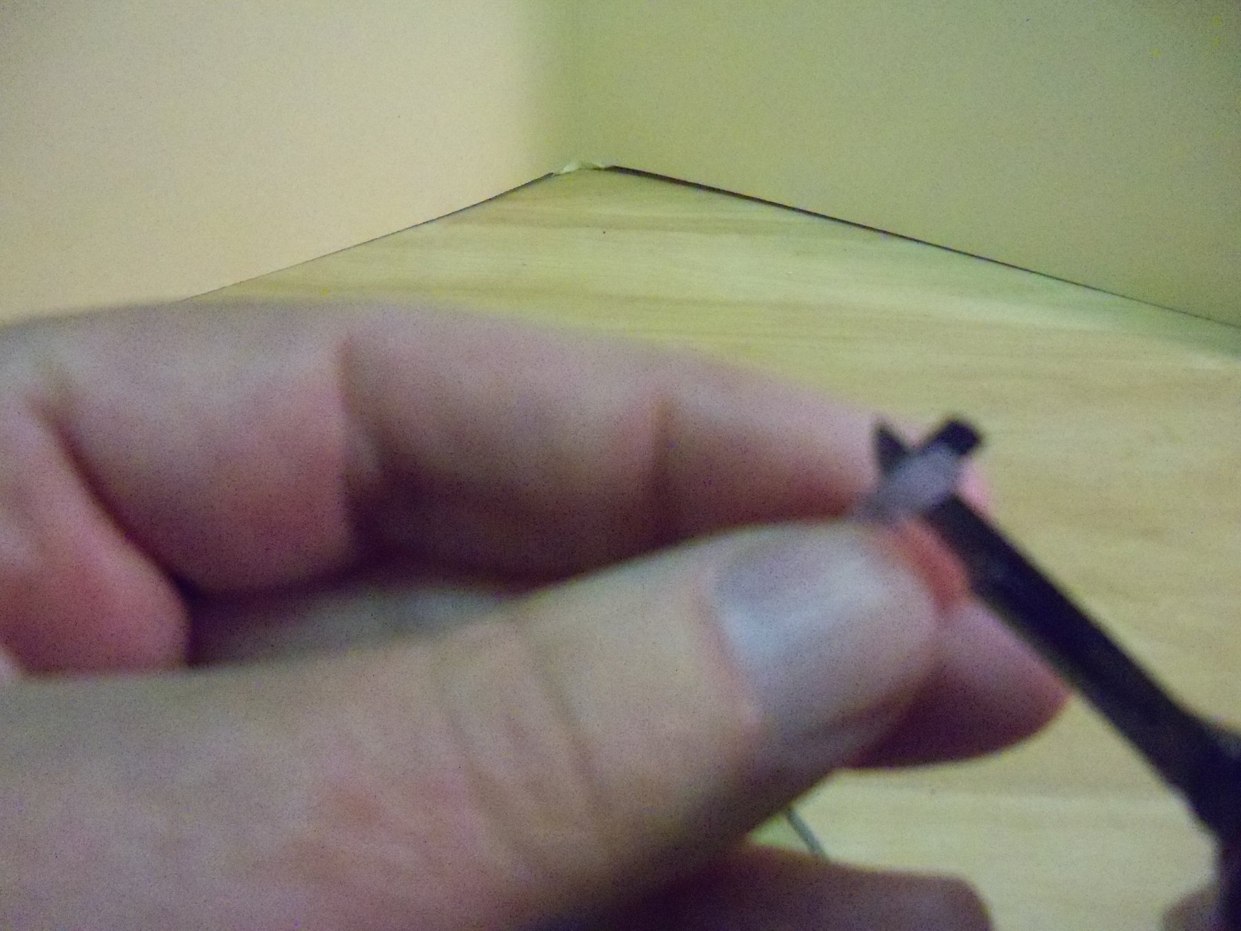
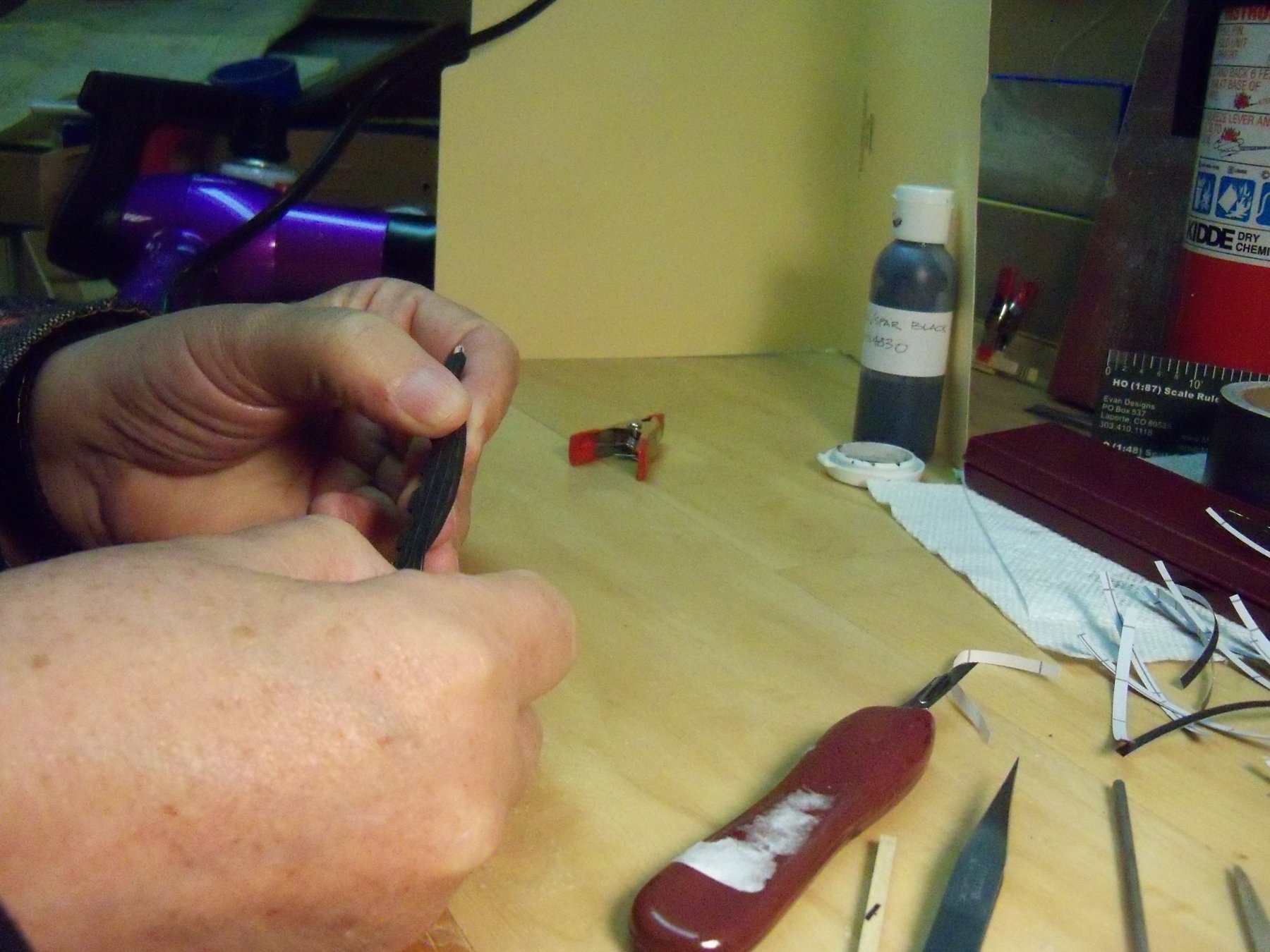
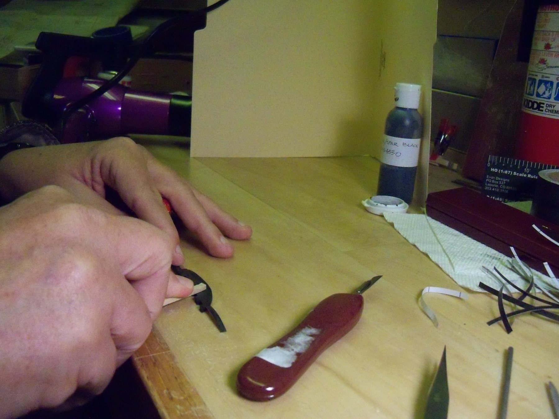
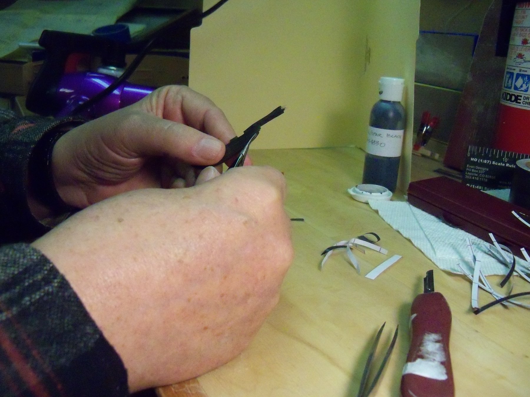
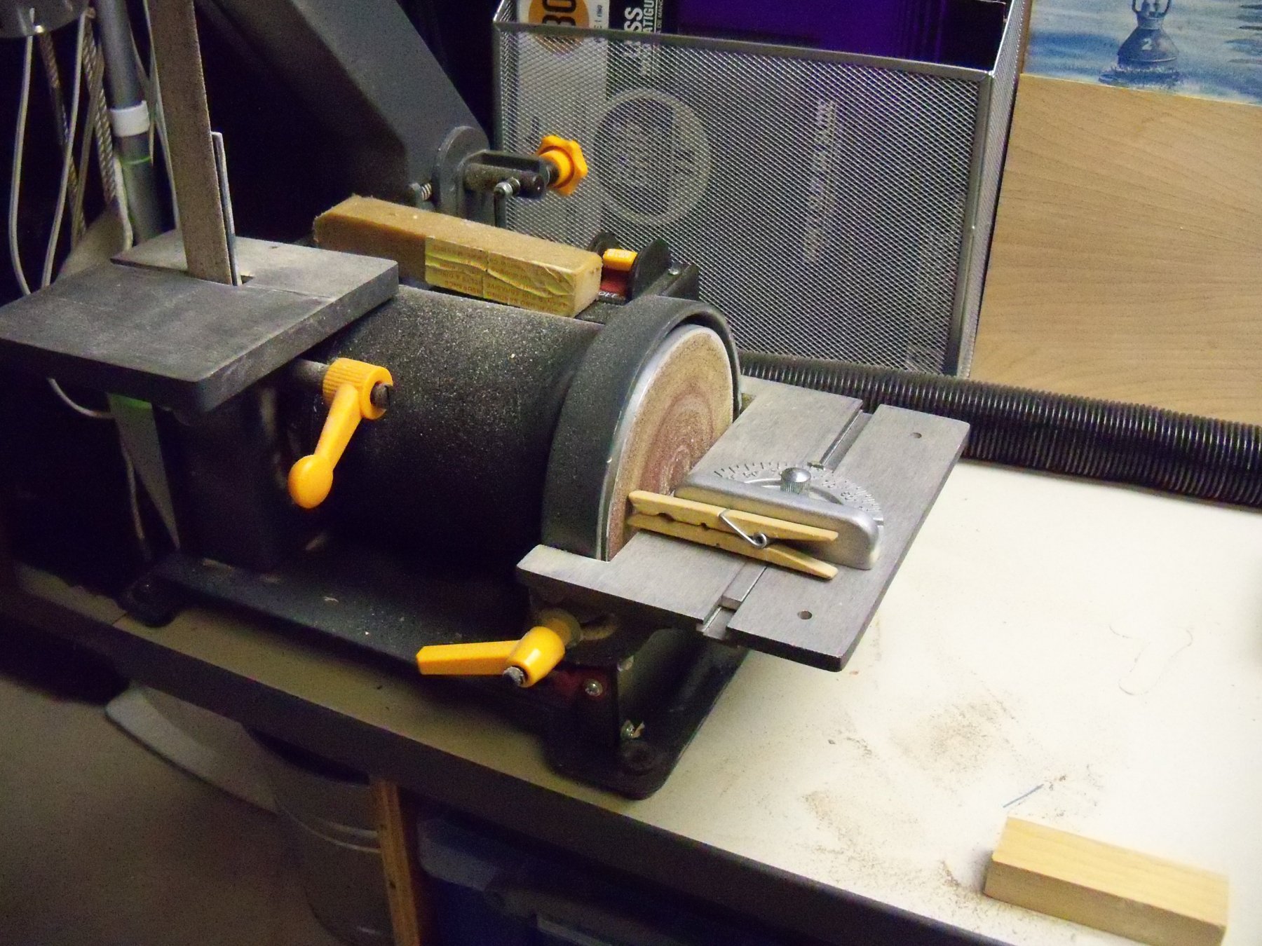
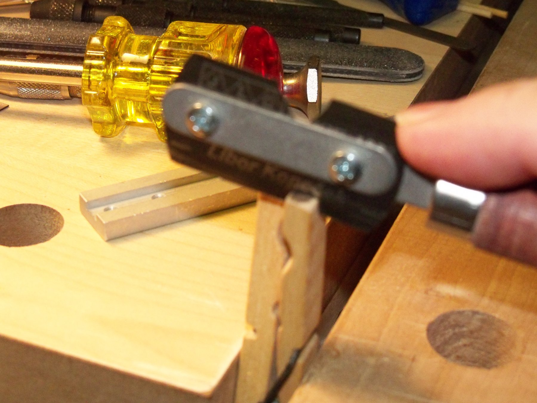
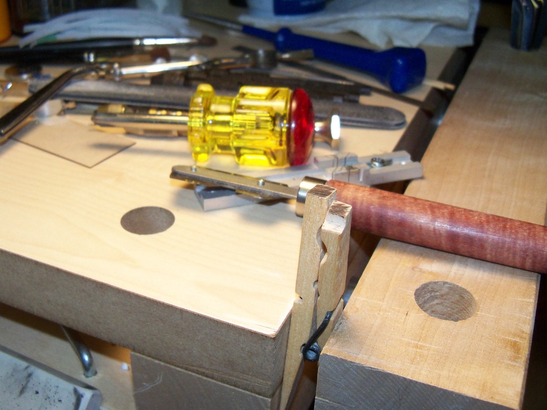
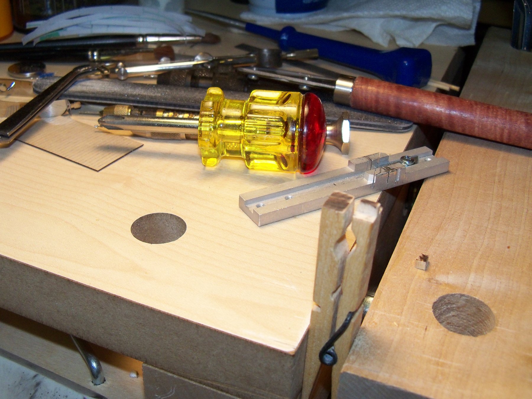
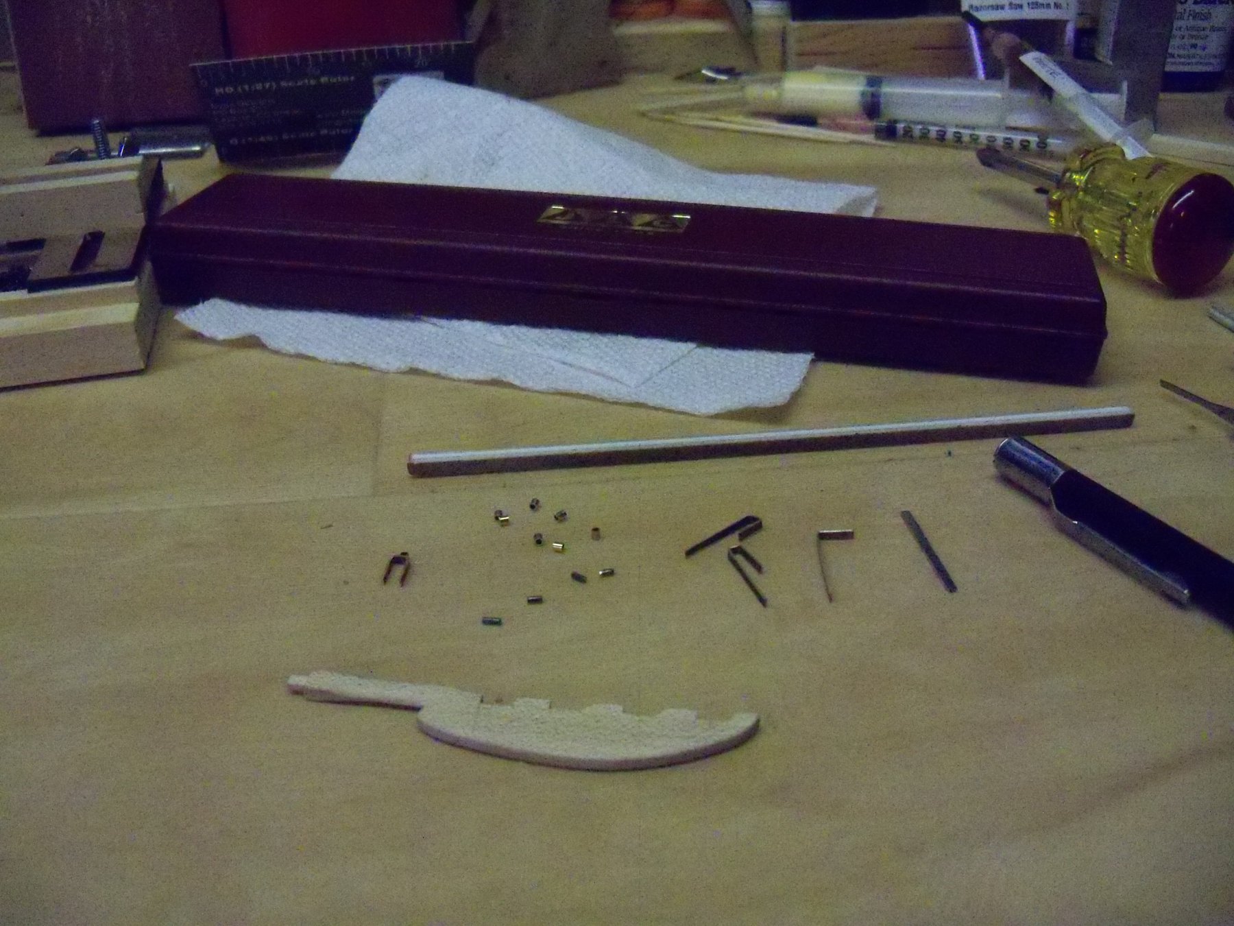
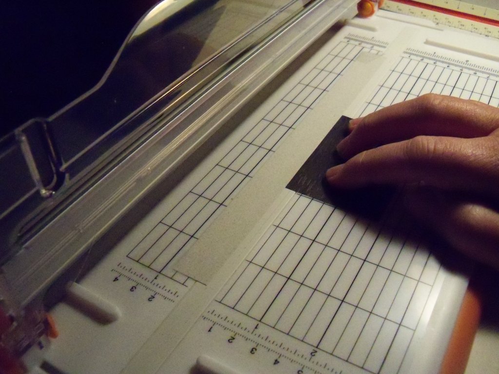
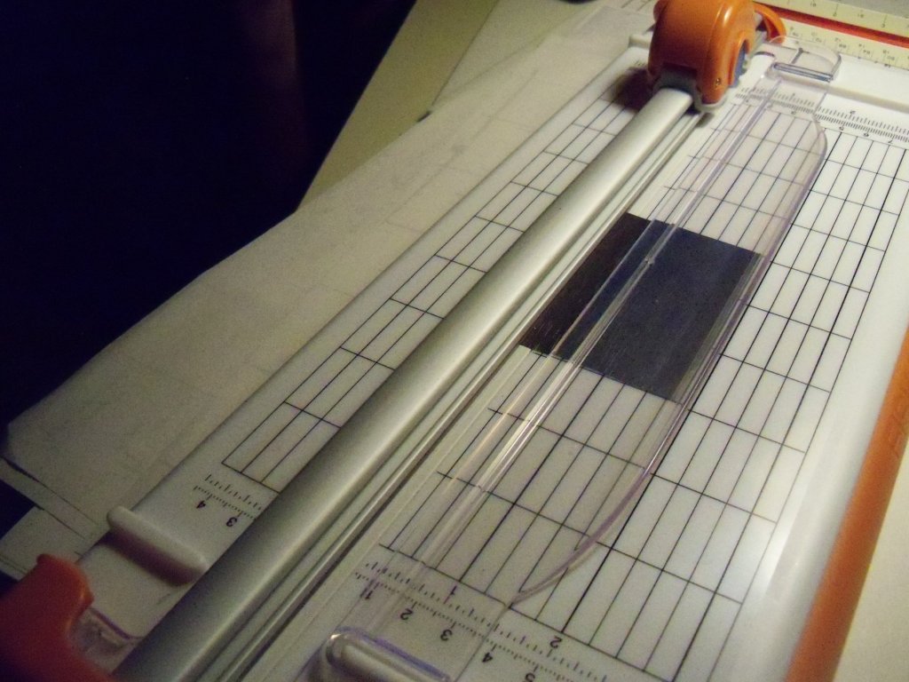
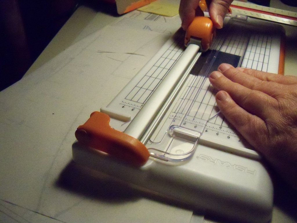
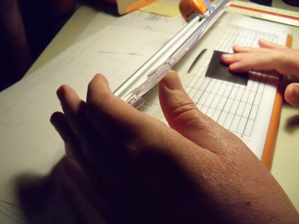
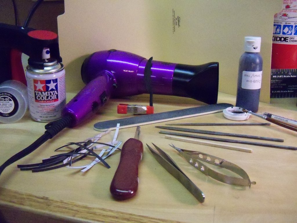
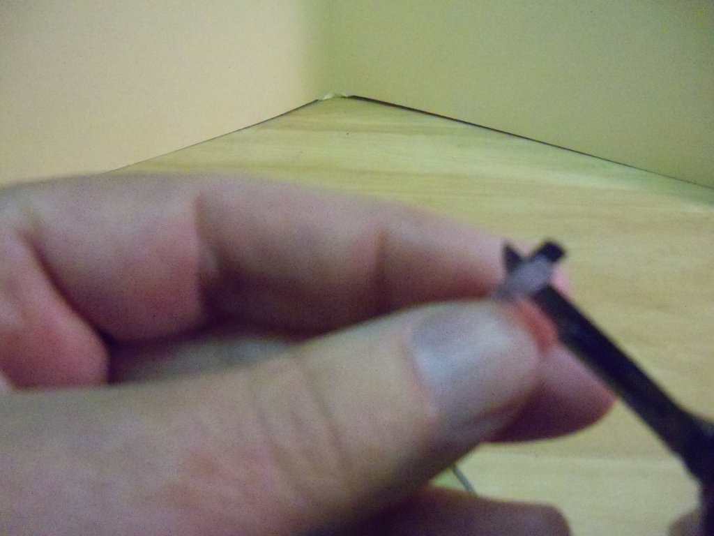
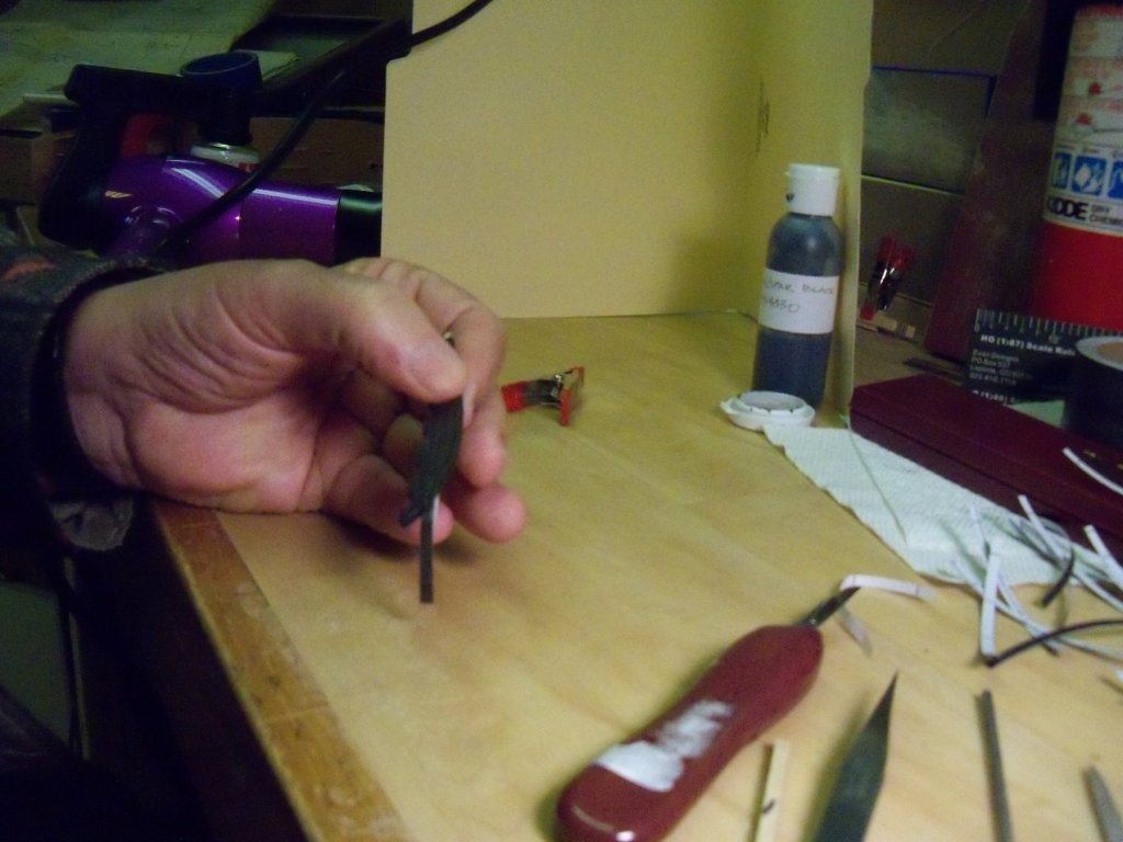
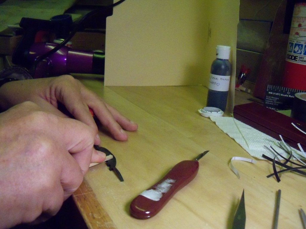
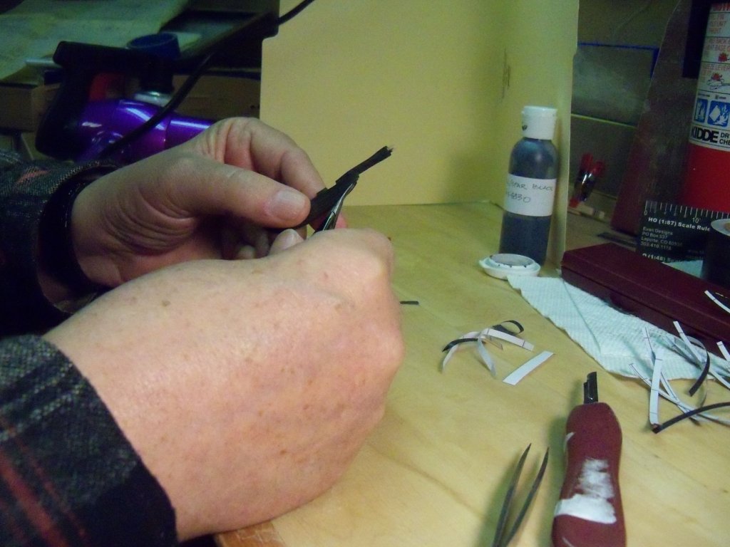
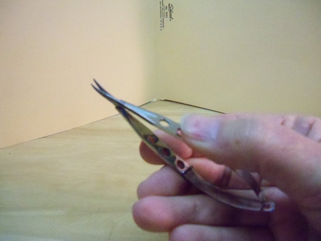
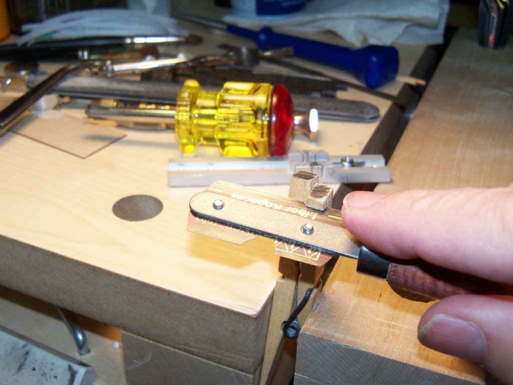
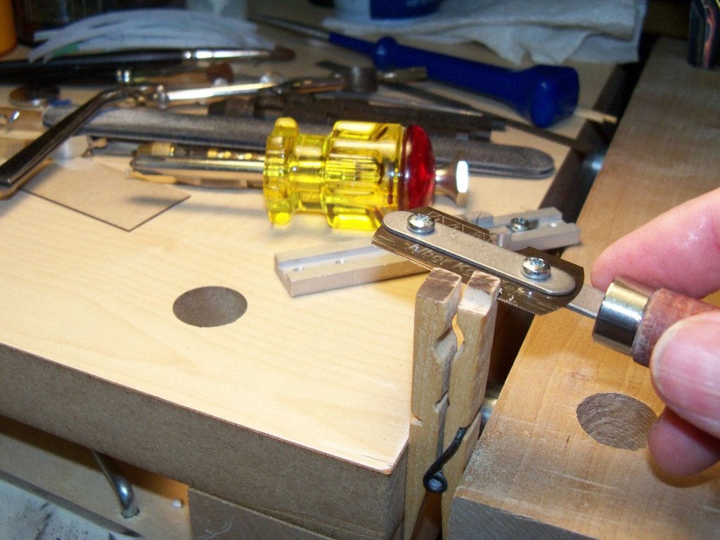
This is the procedure that I have adapted from Doris’s method of applying my vinyl “foils”. While she cuts her planks with a straight edge and a sharp blade, I use this rotary cutter from Fiskars. As the scale that I am working with here is basically HO or close to 1:96, and thus quite a bit smaller than hers, some of my procedures are a little different. By using my 1/8” scale architectural ruler, it’s close enough for me to use for my sizing of components. You can see here that I have taped down a heavy strip of paper for a stop, set at 1/8” or about 12 scale inches from the cut line to represent the individual planks on the rudder. I simply slide my piece of foil up to the stop (finish side up) and hold it in place with my right hand while I lower the cutting guide with my left to hold it down while I make the cut with my right. I run the cutter twice across the foil to ensure a complete cut. Now I just lift the cutting guide to remove the cut “plank” and repeat. Using this procedure I was able to cut all of these “planks” in about a minute. These are the tools and materials (shown below) that I use for application of the vinyl “foils” for the rudder finishing. They include a can of clear matt finish acrylic spray varnish, a 2 speed hair dryer, several strips of self-adhesive black vinyl foil, a scalpel, a pair of fine tipped tweezers, and a good pair of scissors. Also needed is a basswood stick for burnishing, a few misc. fine files, a multi-grit sanding stick, and a small clamp for holding the rudder for spraying. For painting a bottle of black acrylic paint with a small paint brush is needed along with a small plastic cap, and a small syringe with water for thinning the paint solution. The first step for actually applying the foil was to put two drops of water and four of Model Shipways #MS-4830 hull/spar black acrylic paint into a small plastic cap to mix up a diluted paint solution that was applied to the rudder in two thin coats that were both dried with a hair dryer and sanded smooth. (This was one of the few MS paints [that hadn’t turned into a hockey puck in the jar] that I had which was still usable.) I transferred the paint into a flip cap covered plastic bottle that I picked up on Amazon that allowed me to dispense the paint by the drop, and gives a positive seal for preserving the paint. A light spray of Tamiya TS-80 clear matt acrylic varnish was applied and dried with the blower. (Notice the spray can holder that was clipped onto the can that allowed me to use the spray. My MD really limits my finger strength and this holder allows the use of four fingers rather than just one.) The only tedious part of using the vinyl foils was removing the foil from the backing with a scalpel as it takes a steady hand and eye to get it to separate. Once one end of the foil was separated and put in place with a pair of tweezers, I pressed it down with my thumb and used the tweezers to steer the rest of it loosely in line. While still holding one end of the foil with one hand the other hand grips the excess lose end, stretches it slightly and presses it down tightly to hold it in place. Once the foil is stuck in place, I use the dryer to heat it and use a wood burnishing tool to firmly secure it to the rudder. Taking my Curved Surgeons Castroviejo Scissors, I trim the excess off as close to the edge of the rudder as I can. (These light weight scissors are spring loaded with super sharp jaws that have anti-slip microscopic serrations that cut like a dream allowing me to get in real close. I think that I need to order myself another pair with the straight jaws.) Now I spray another light coat of varnish on the rudder and heat it again with the dryer. Since the edge of the rudder is slightly rounded, I use the burnishing tool again to make the edge of the foil follow the curve. Next, I used fine files and sandpaper to carefully trim the edge of the foil back to where the edge started to round over. Then I trimmed all of the remaining square edges of the rudder. Since this procedure usually removes some of the paint on the edges, I re-coat the entire rudder with another layer of paint, and it’s once again dried with the blower. Once I am satisfied, the rudder has a final light spray of varnish applied and dried. And Walla, it’s done!!! My next step on this build will be to continue working on the pintles and gudgeons.


-
Jesse, it seems to me that I have come across a MSW log that showed a light weight dust cover. It was just a light weight wood frame with a clear plastic film stretched over it. It was easily removable, so whenever he was done with his ship for the day, he just put the cover over it. Of course, the aerosol cans would be simpler and cheaper, so to each his own I guess. If I can recall where I saw it I'll let you know so you can decide if it's something that would interest you.
- 1,306 replies
-
- 6
-
-
- syren
- model shipways
- (and 1 more)
-
Yes, but it appears to me that it's a movie about a ship being built by a team of robots who are overly proud of their creation. They are holding it overhead looking for approval by their adoring fans.
-
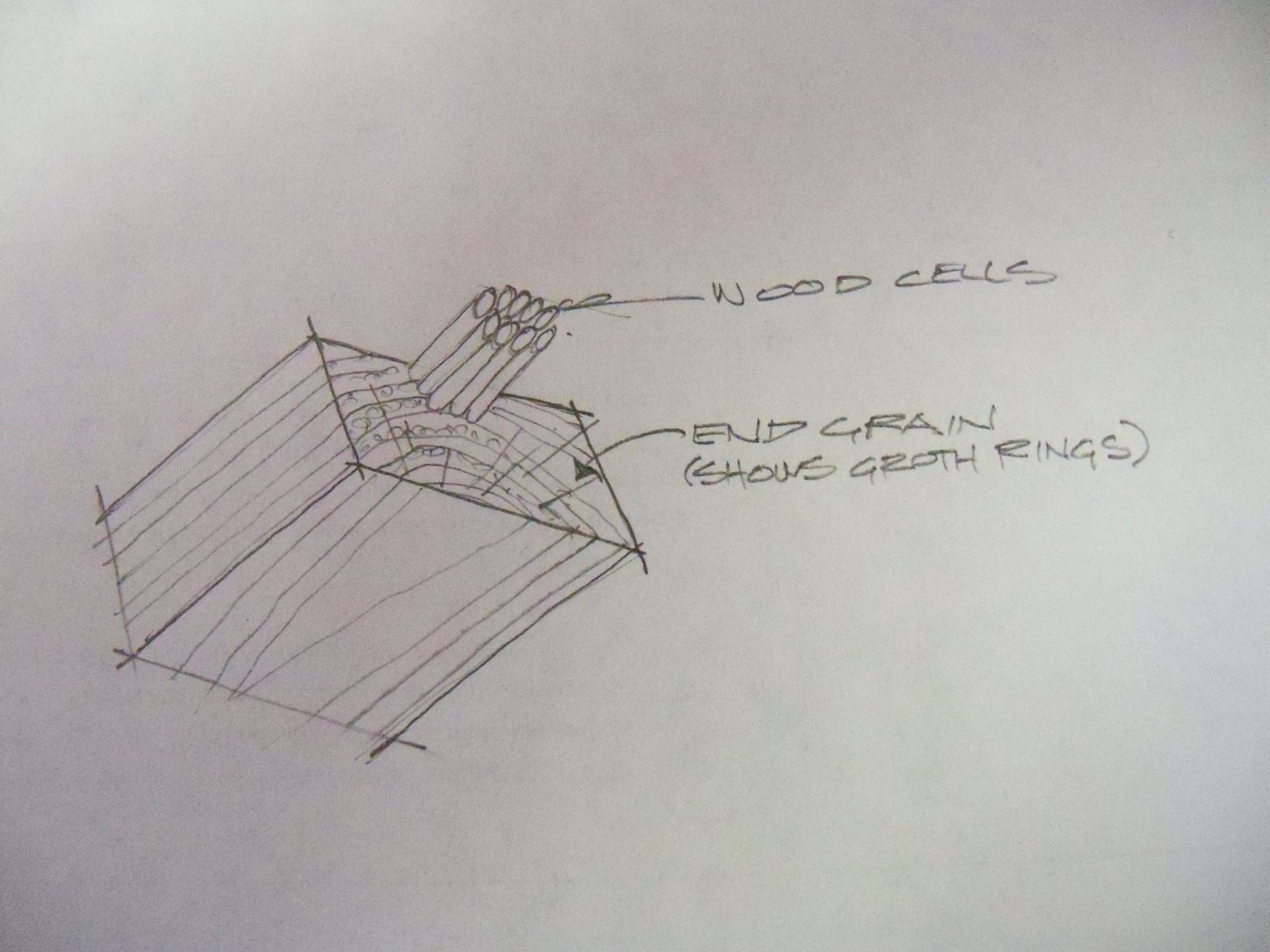
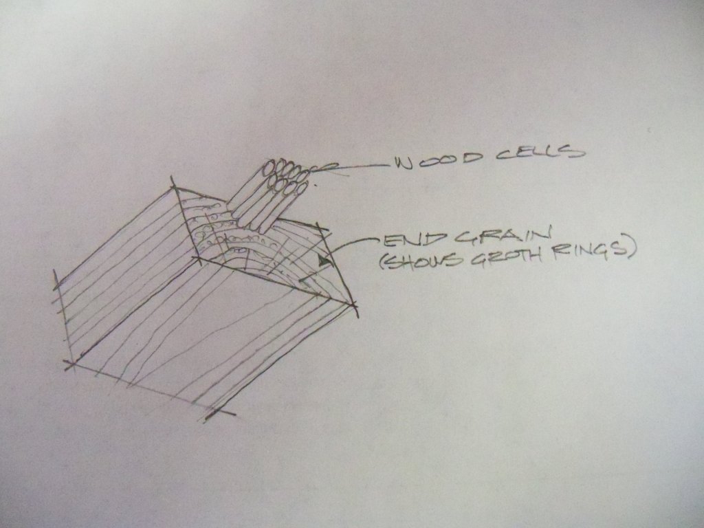
The man next door (and Wallace) are correct. No matter what kind of wood it is, the end grain is always tougher to cut across. (as you have discovered) Think of wood as a bundle of long skinny tubes (wood cells) bound together that run longitudinally the length of the wood. My sketch here shows some of these cells very greatly enlarged bundled together as I said. They serve as conduits for moisture and nutrients to travel from the tree roots to the other parts of the tree. When you look closely at the end of any board they will appear as round or oval shapes in alternating lighter and darker rings called growth rings. If you cut down a tree and look at the stump, you can tell how old the tree was by counting the number of these darker rings as each one indicates the end of a years growth. On the other hand, if the grain appears as long stretched out lines as shown on the sketch you are looking at the side or longitudinal grain. When you cut wood along these lines you are following the grain of the wood and will find it much easier to slice through. Just take a chisel and try cutting your wood in both directions. You will find that when you follow the side grain it will smoothly slice off easily, but the chisel will want to chatter across it on the end grain for a much rougher cut. Whenever possible, going with the grain will be easier than going against the grain. (Somewhat like life in general, I guess.)
-
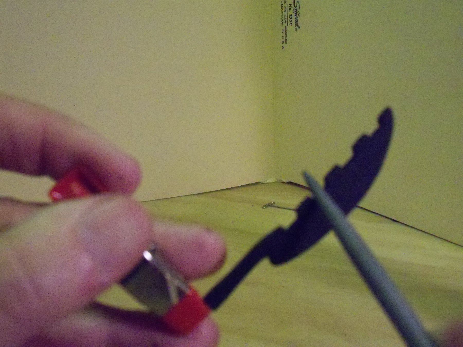
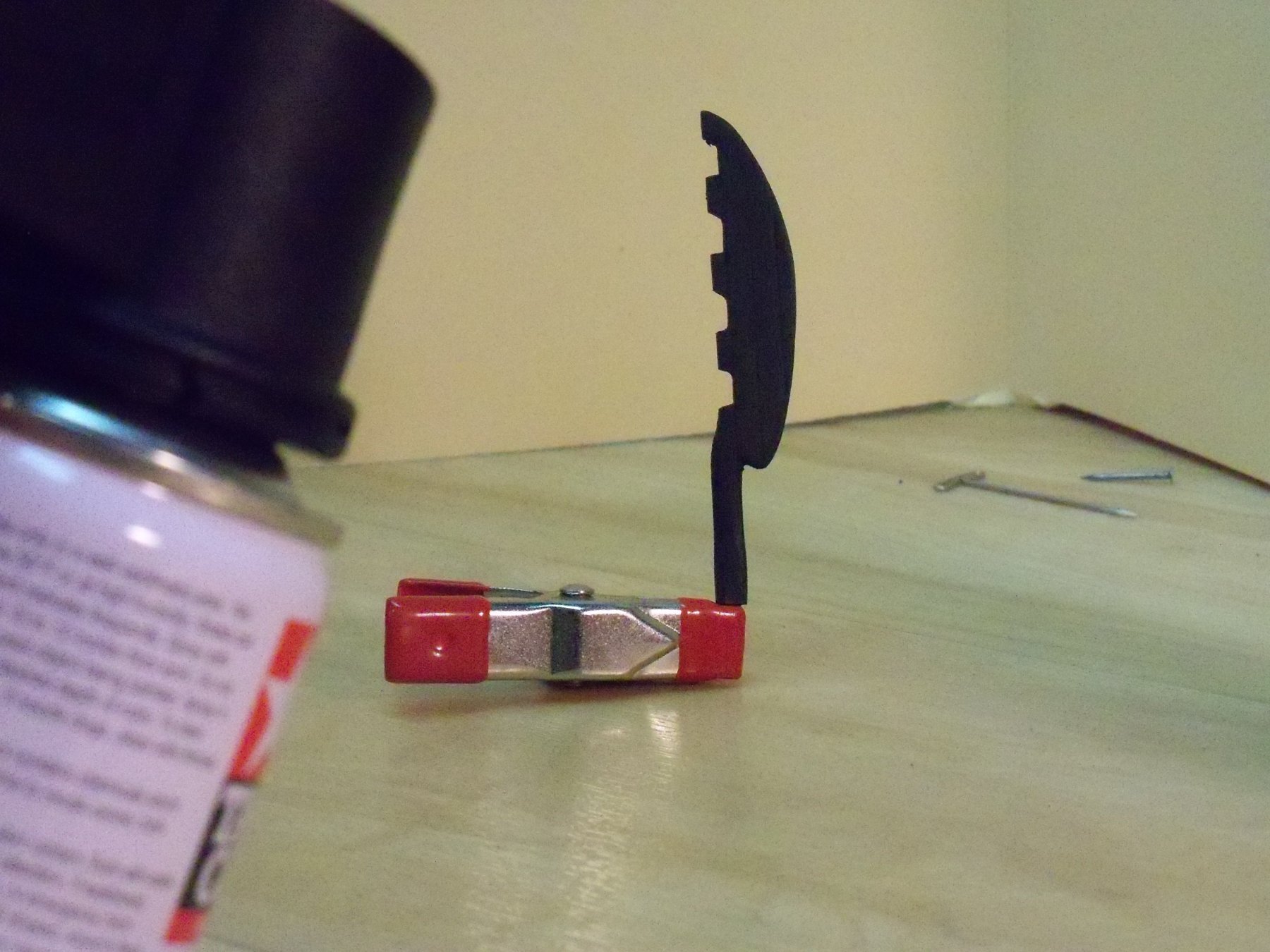
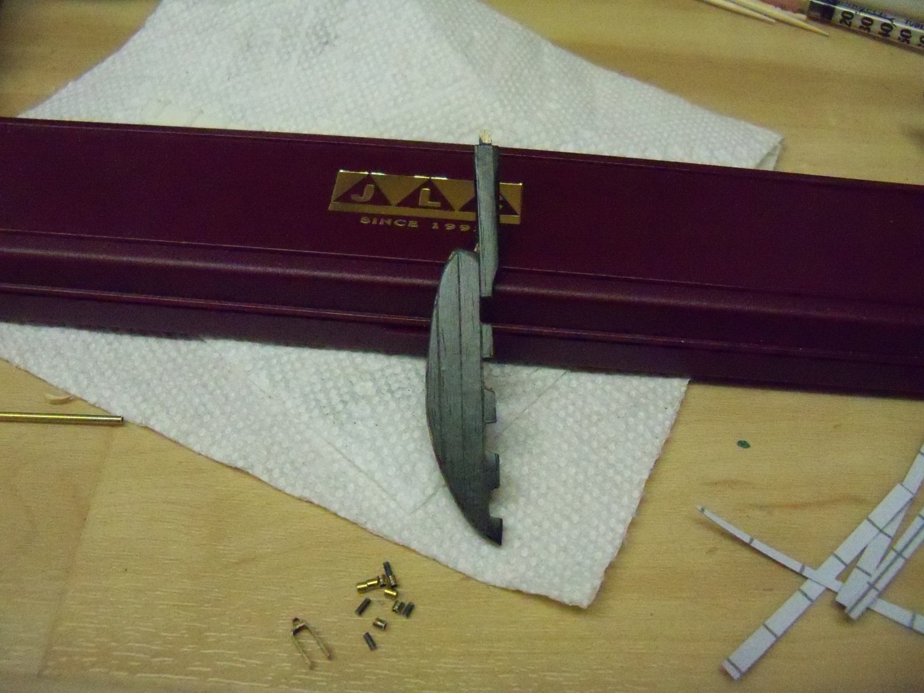
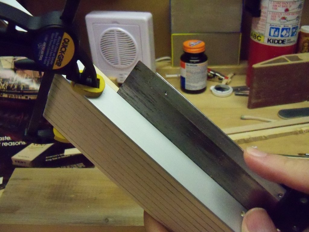
Just a short update here. I took the rudder blank in hand and applied some of the black wood grained adhesive backed vinyl foil to one side to test out it's work-ability on an uneven shape. As you can see here, it can be effective when applied with the method described by Doris. I think that it clearly shows how a single piece of wood can be given the appearance of several separate pieces. Both the variation in the grain pattern and the appearance of wood joints contribute to this effect. Later, I will try to illustrate in more detail just how I did this when I do the opposite side, now that I think I have it worked out to my satisfaction.

-
Filler Blocks
BETAQDAVE replied to olopa67's topic in Building, Framing, Planking and plating a ships hull and deck
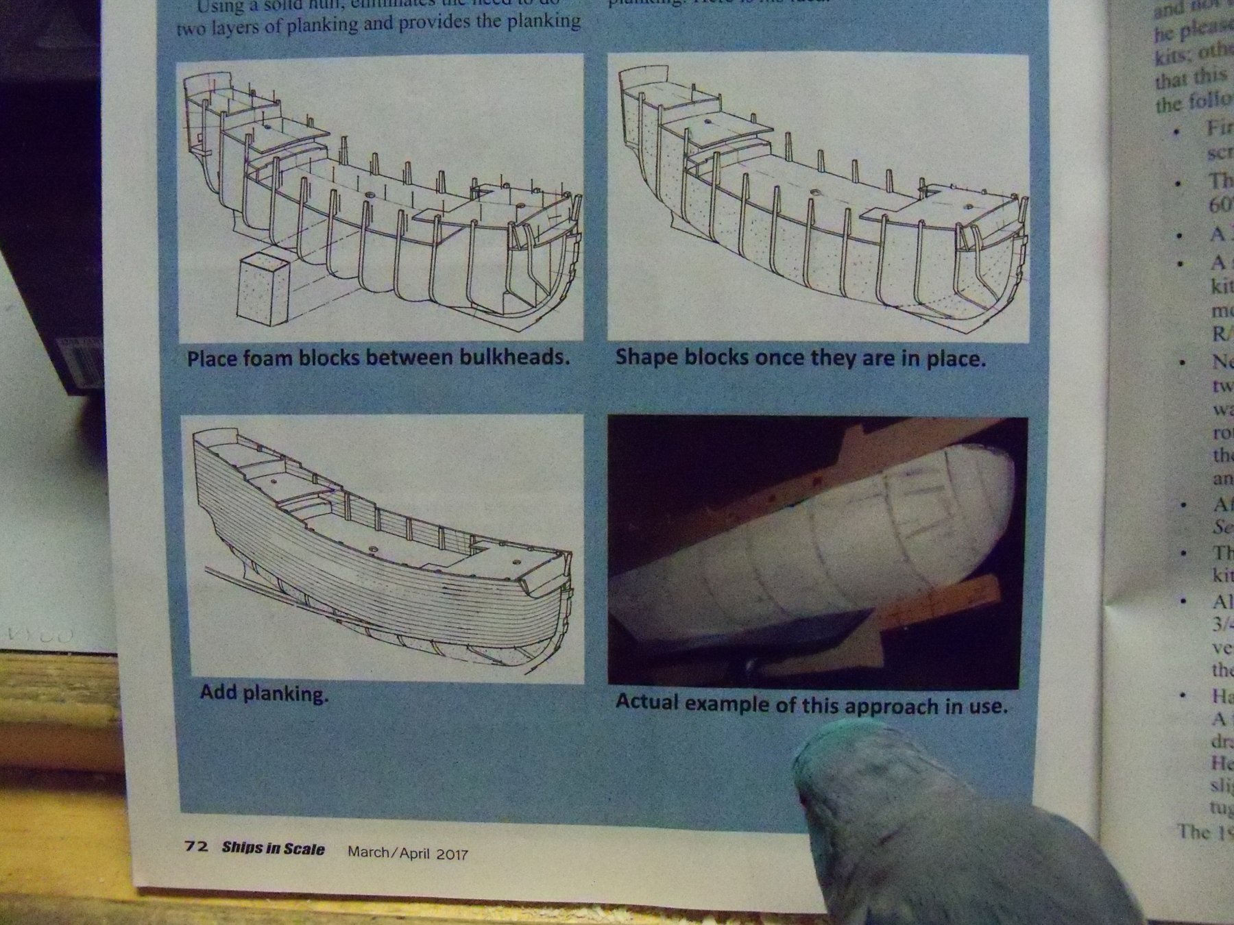
When I first saw this posting of this topic, I was reminded of seeing that in the March/April issue of Ships in Scale there was a short article on converting POB construction to solid hull construction by Robert Brandt. In his article, he described his method of using foam blocks to fill in between frames allowing him to use a single layer of planking that would have continuous solid support and eliminate the problem of hollow spots in between frames. (Something quite important if you intend to use a natural finish rather than painting the model.) He thought that by using extruded polystyrene foam for his blocking, the ease of cutting and shaping the blocks was easier than using wood. As an added bonus this would add very little in terms of weight. The excellent compressive strength of this type of foam doesn’t hurt either. Shown below are the illustrations of his method that were shown in his article. (Currently being reviewed by my assistant.) A version of this type of foam that is readily available throughout North America is Dow Blue Styrofoam. STYROFOAM™ Brand Insulation is the original extruded polystyrene foam insulation, invented by Dow and first manufactured by them in 1941. Dow's blue colored extruded polystyrene Blue Board's closed cell structure and lack of voids resists water and water vapor penetration thus protecting underlying materials from water damage. This product is also available in several sheet sizes and thicknesses and is relatively inexpensive. It does however, require the use of a particular type of adhesive, as some types of adhesive will dissolve the board.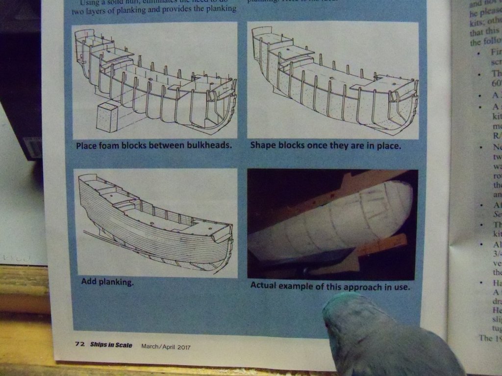
-
Harbor Freight Hardwood Workbench Kit Bash
BETAQDAVE replied to thibaultron's topic in Modeling tools and Workshop Equipment
Ron, with all the reinforcing you've added to the bench it should be quite stable now. -
I hope the captain has plenty of odor eaters, as a foot that size would surely have left quite a stink!
-
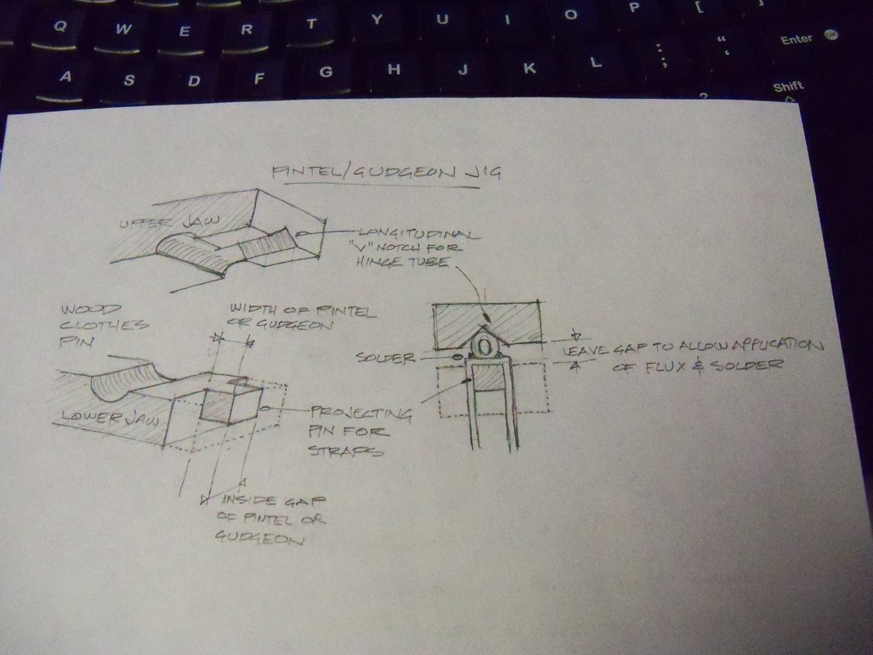
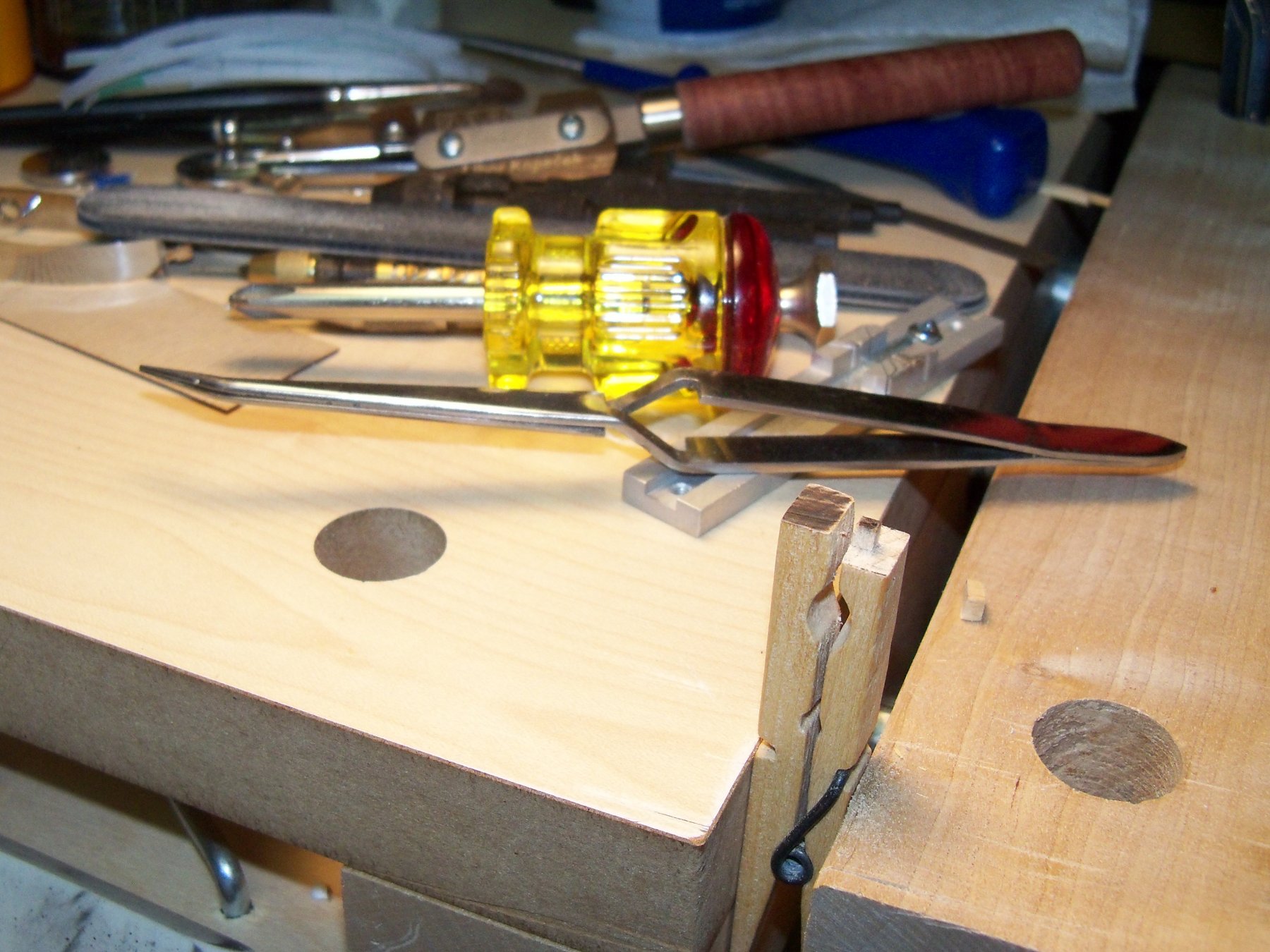
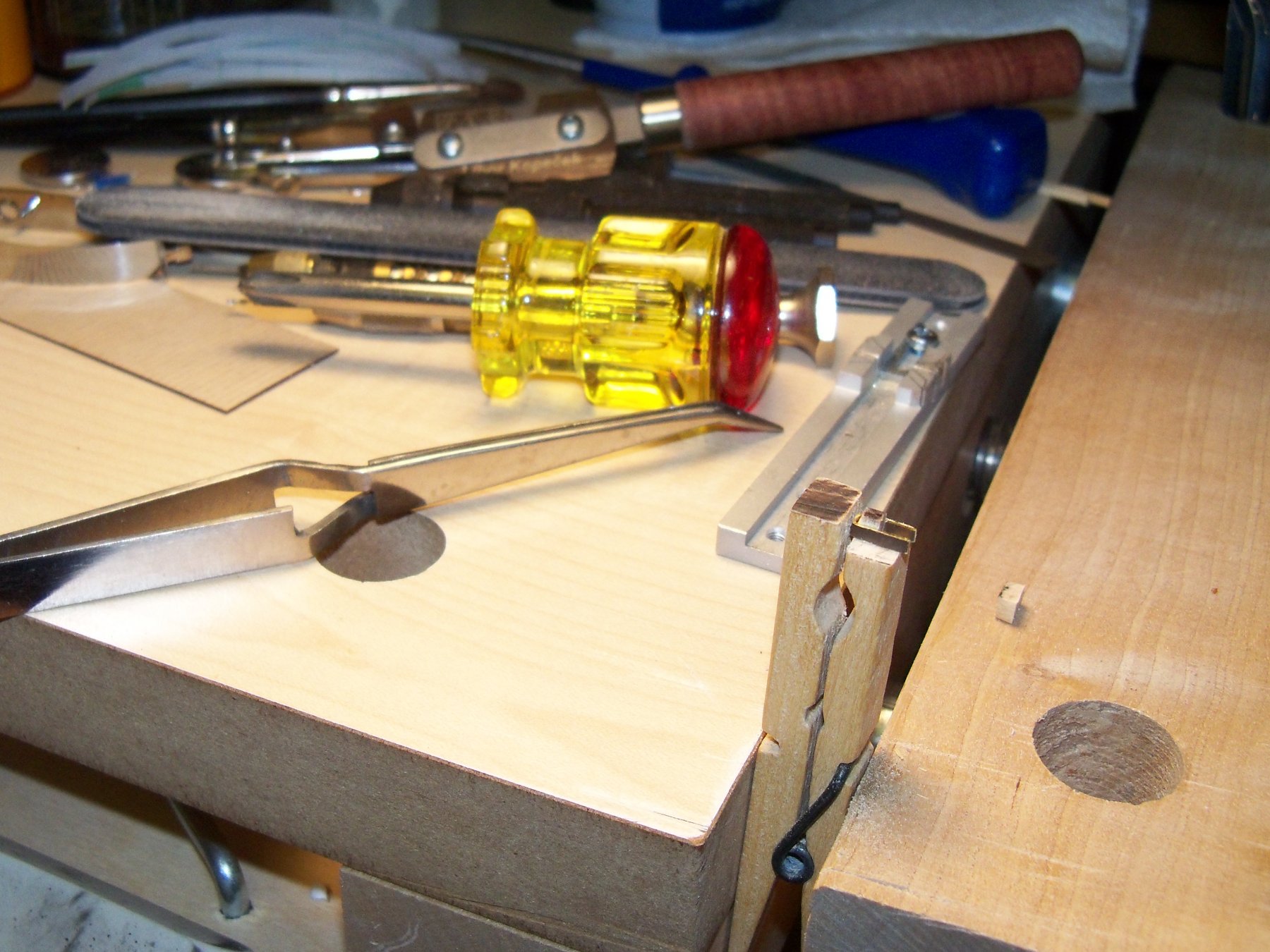
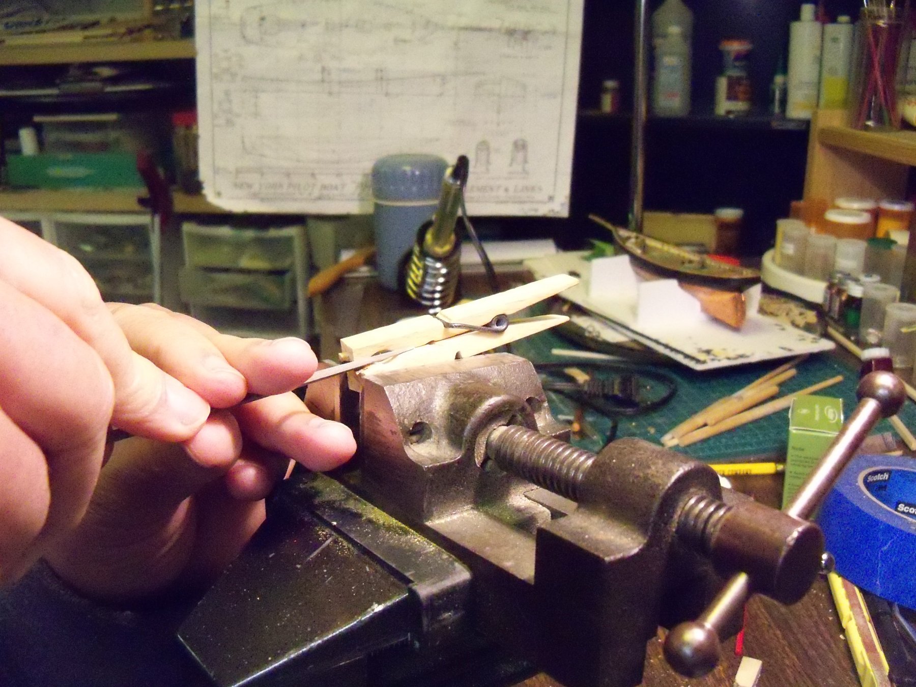
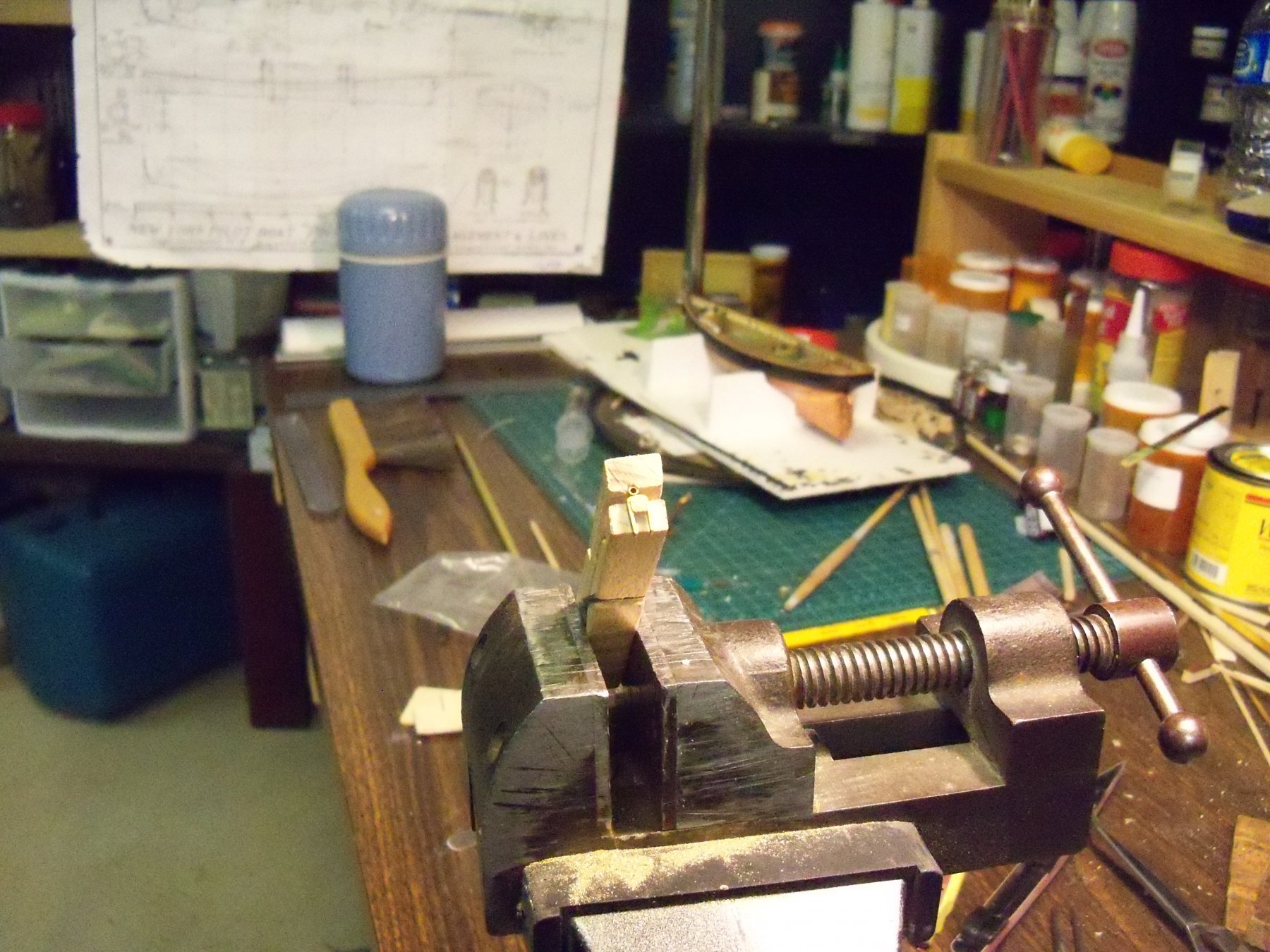
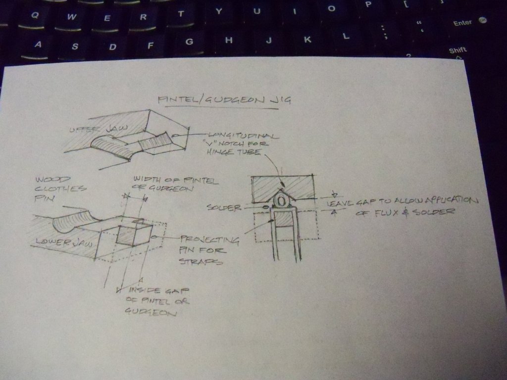
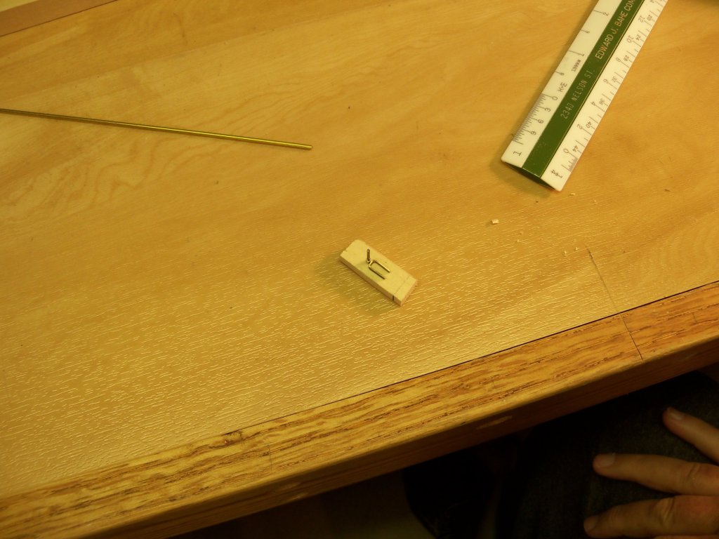
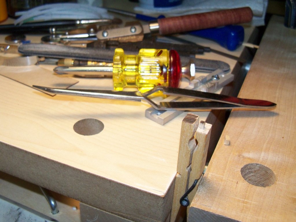
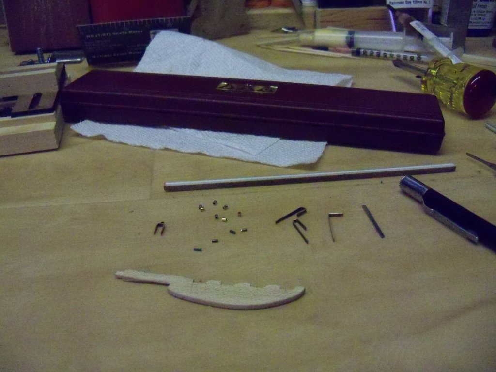
I was finally able to get back in the shop to start making the pintels and gudgeons for the rudder which has turned into quite an involved little project of its own. The first step was designing a jig to hold the parts while being soldered. I sketched up the jig design first on paper to save a lot of wasted effort of fiddling around cobbling together something that wouldn’t work anyway. By taking a common spring wood clothes pin that would, with some modification of the ends, give me a jig that would also serve as a clamp. Having already cut the 1/16” wide straps from some .016 brass, I cut eight 1/16” lengths of 1.56 mm thin wall brass tubing and four pieces of 1.02 mm piano wire in 1/8” lengths for the pins. I bent one of the straps over the rudder to the required size to test the fit. So, now the required parts for one of the hinges have been made to help me size the jig/clamp and are show here. Taking the clothes pin to my disc sander, I sanded the ends of the pin flush and square. Then, by twisting the ends of the clothes pin to offset them, it allowed me to clamp it in my woodworking vise without taking it apart and work on shaping the top and bottom jaws separately. The bottom jaw was done first. My razor saw was well suited to the task, as it easily cuts a very thin kerf in the hardwood pin. The projecting pin was roughly sized to be in the center of the pin. The left side was sawn first, cutting somewhat deeper than was needed to make the face cuts a little easier. The face cut was then made to remove the left side. The right side was done similarly after sizing the width of the projecting pin by placing the formed strap on the end for a direct measurement, rather than using a ruler, to guarantee a good tight fit. Now the lower half of the projecting pin was also removed. The strap was placed over the pin to allow the length of the projecting pin to be marked. Now the jig/clamp was set in my machinist vise where the projecting pin was filed down to my mark and I filed out a V groove in the top jaw of the clothes pin with a square edged file to hold the hinge tube in place. Now the strap and tube were clamped in the jig to test how well it would actually work. Using a very small brush, I spread some solder paste on the sides of the tube and top of the strap. I cut some chips of solder and placed them in the pasted joint. (That’s one time were the paste does triple duty. It cleans the parts, controls were the solder flows, and being sticky, it holds the chips of solder in place.) Rather than using my soldering torch and destroying my jig/clamp, I opted for the soldering iron. All I had to do was touch the hot tip of the iron to the end of the tube, and within a second or so, the paste burned away, leaving the solder to flow into the joint. The jig/clamp lives on now to do the job on the other seven fittings! This shows the components needed and the straps in various stages of their shaping. That's as far as I was able to get, so I still need to finish the other seven fittings and work out the actual installation on the ship and rudder. I will also be attempting to cover the rudder with some black vinyl foil as I don't believe that the rudder was copper plated.


-
Likewise. Looks like you've done quite abit of work on your ship since your last post Jesse.
- 1,306 replies
-
- 6
-
-
- syren
- model shipways
- (and 1 more)