HOLIDAY DONATION DRIVE - SUPPORT MSW - DO YOUR PART TO KEEP THIS GREAT FORUM GOING! (Only 13 donations so far - C'mon guys!)
×


BETAQDAVE
-
Posts
5,386 -
Joined
-
Last visited
Content Type
Profiles
Forums
Gallery
Events
Everything posted by BETAQDAVE
-
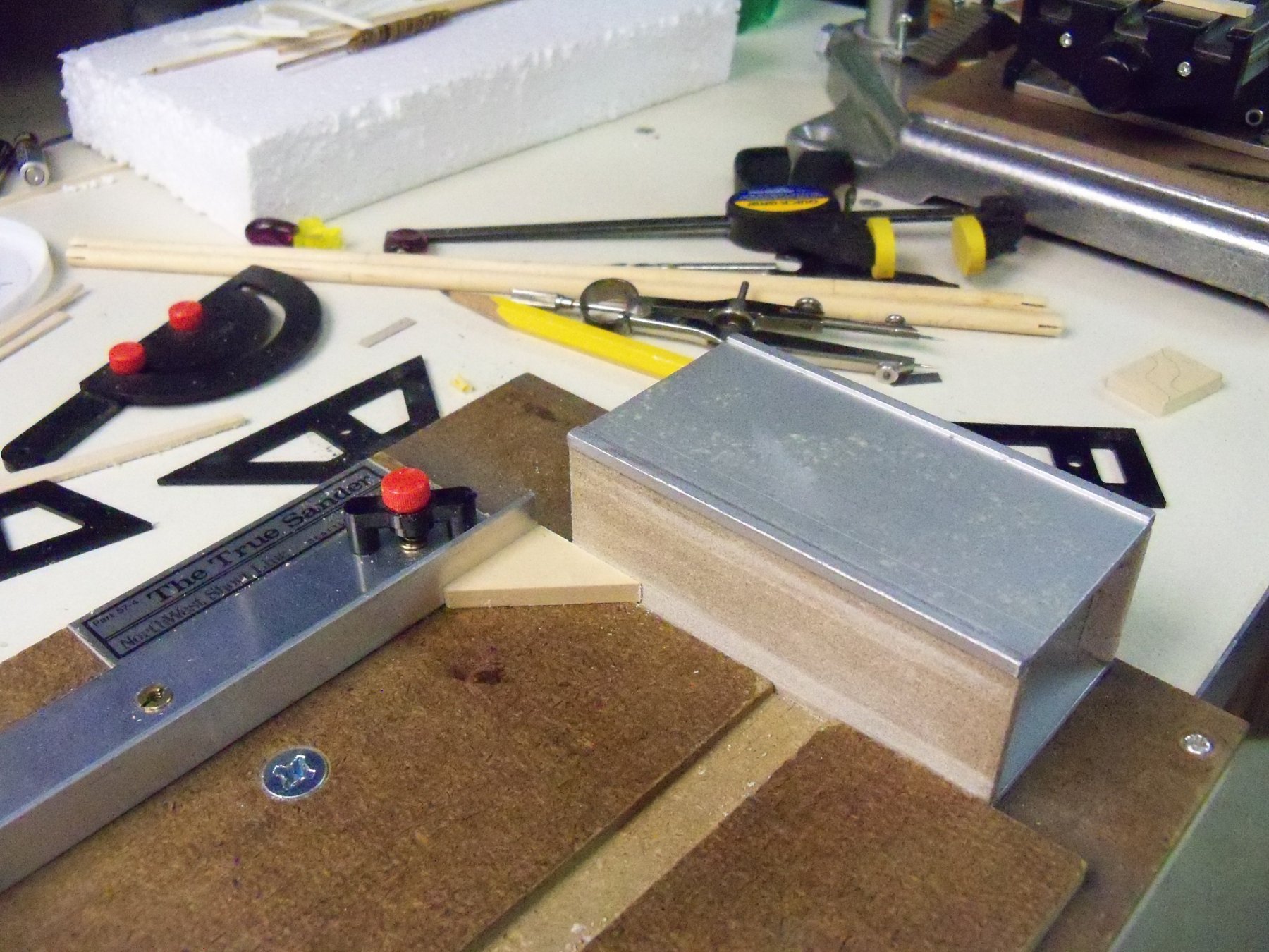
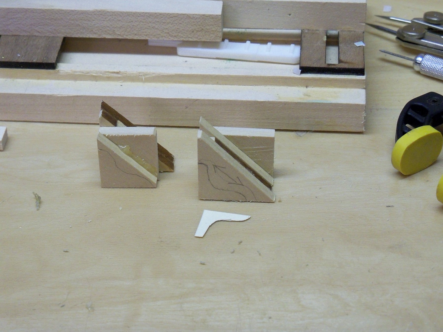
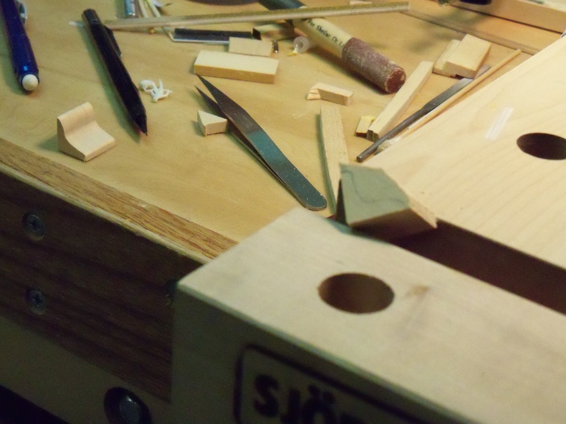
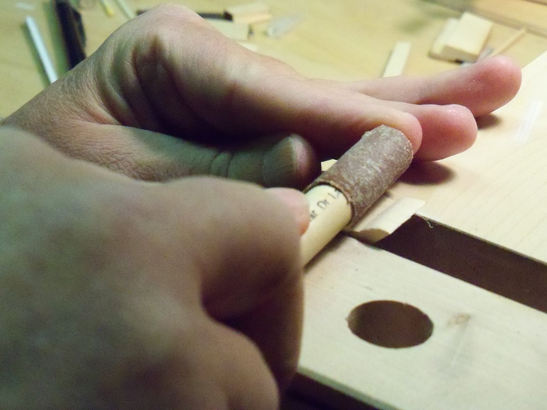
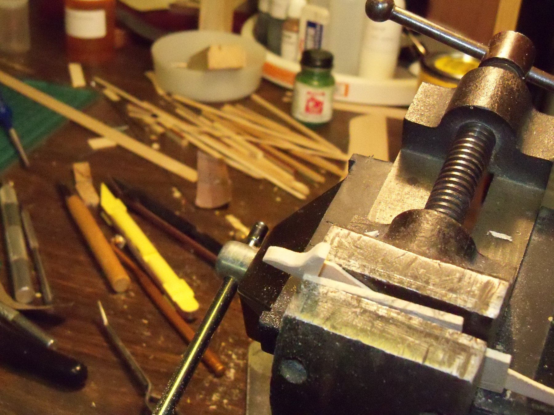
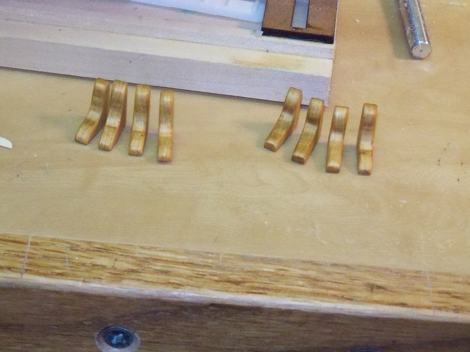
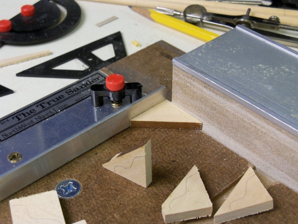
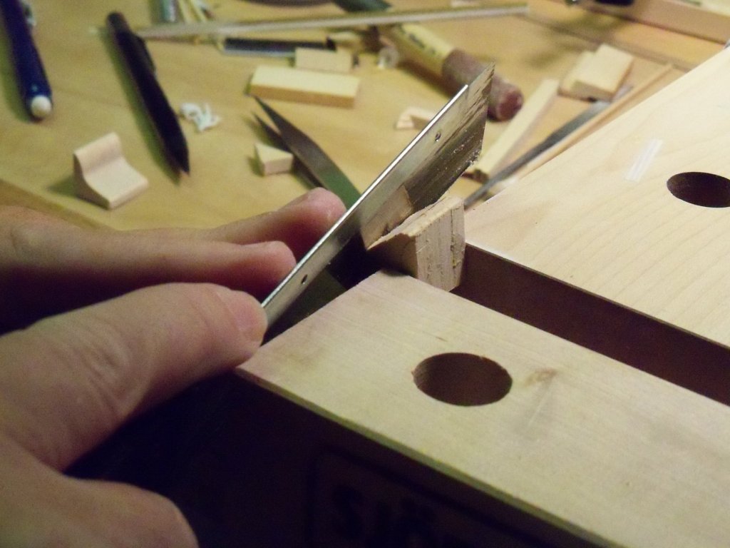
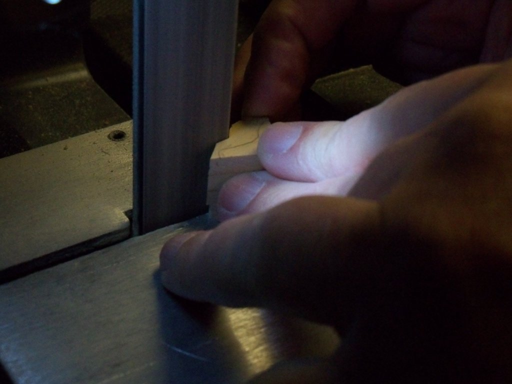
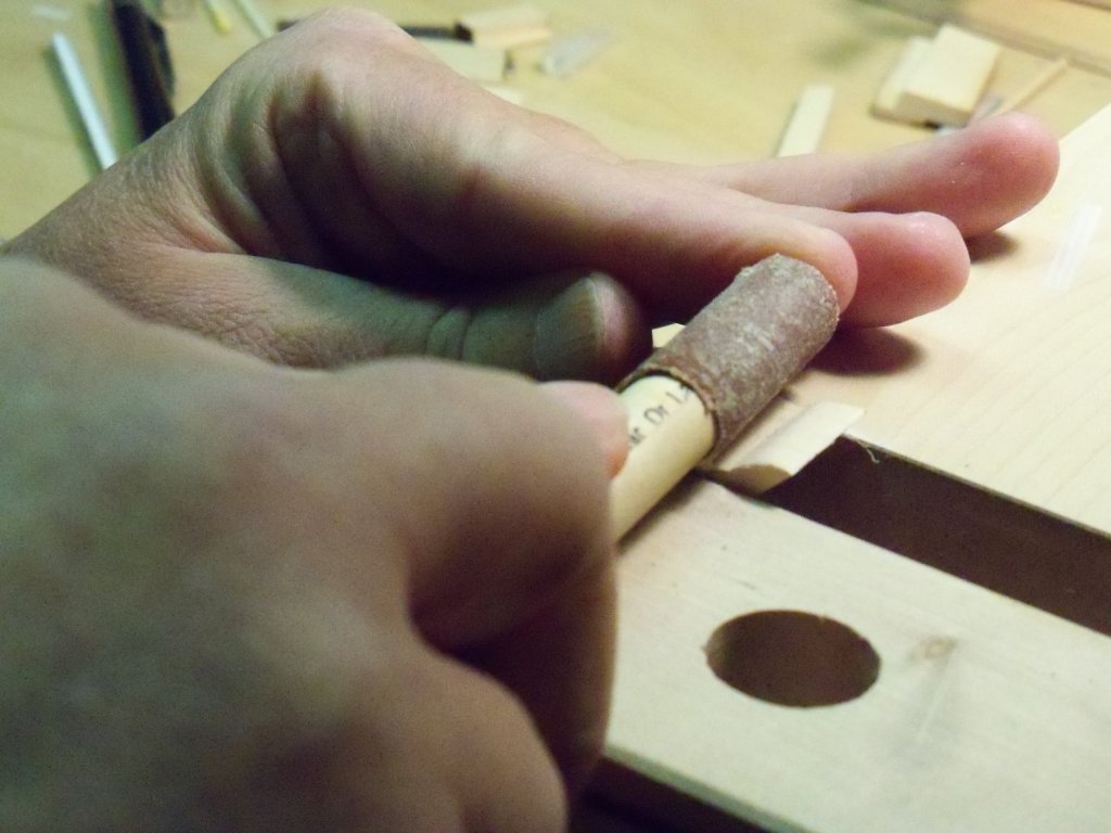
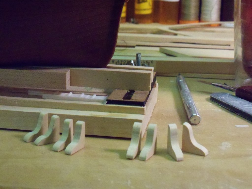
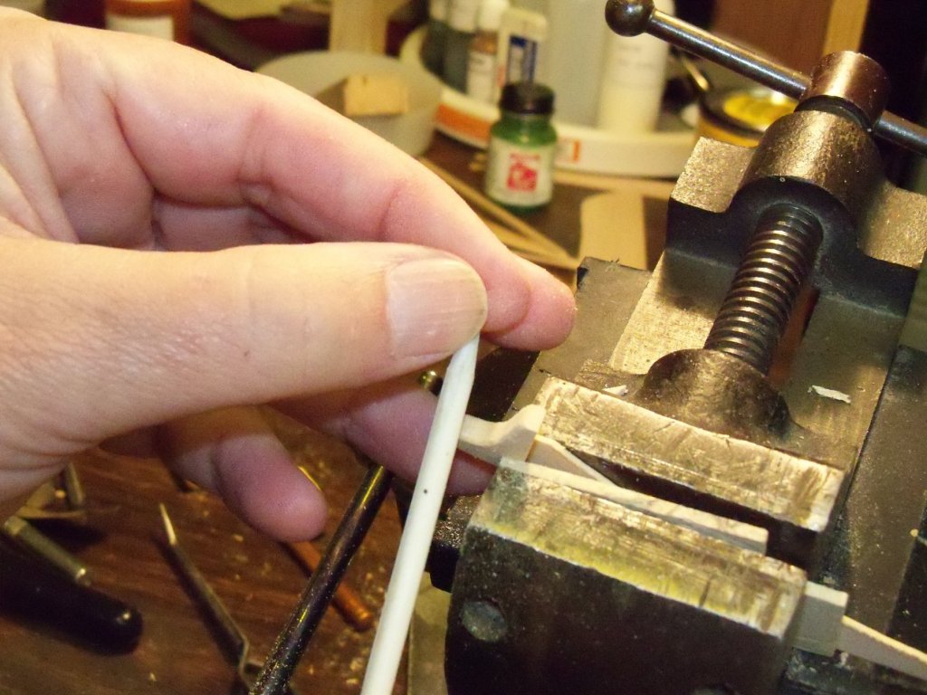
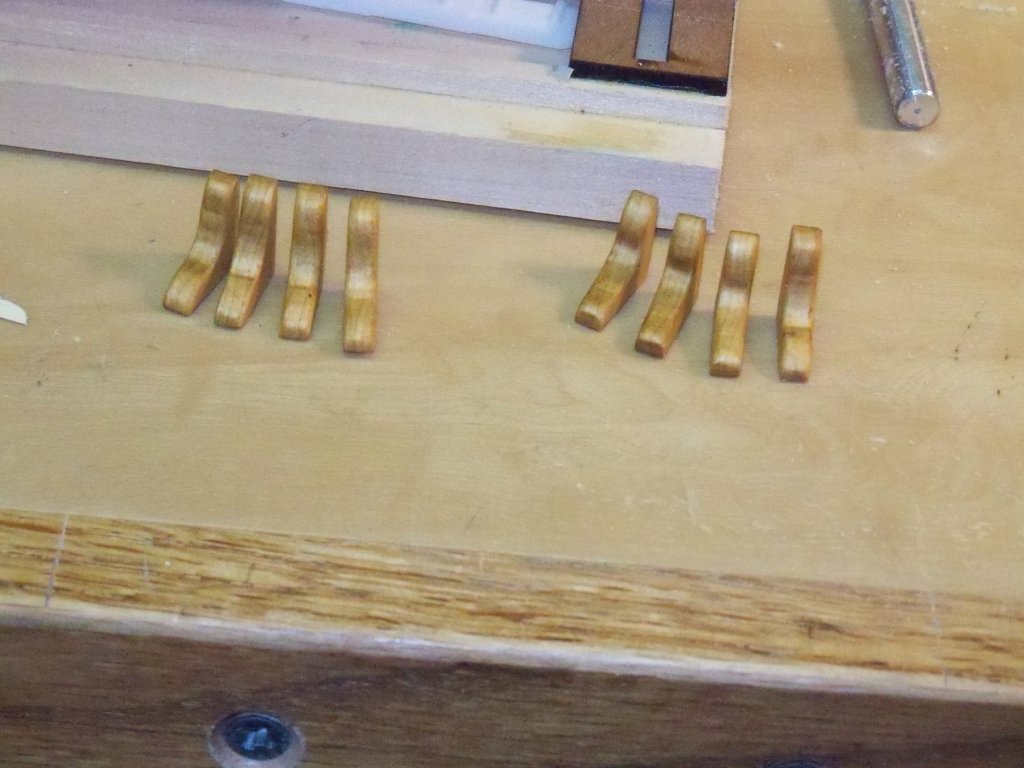
 Now here is my knee production method. First off, I took a billet of basswood of the desired thickness and cut triangular pieces with the grain running parallel to the long edge. The remaining edges of these pieces were squared up with my sanding fixture as shown here. Then I drew a rough outline of the shape of the knee on all eight triangles to help keep track of their orientation, as one leg was longer than the other. These were grouped in sets of four that were glued up with a thin coating of rubber cement on all the facing surfaces and clamped in place overnight to dry. The next day I drew the pattern on a stiff piece of manila folder and cut it to shape. Holding the pattern in place on the face of the glued up blocks, the pattern was traced onto the top blocks. I clamped the blocks in my vise and using a small back saw trimmed off the majority of the waste. The blocks were then sanded close to the outline of the knees on my 2” belt sander being careful keep the block flat on the table. Now, using several grades of sand paper on sanding sticks the blocks were sanded to their final shape. Now the blocks were separated from each other with a chisel driven into the glue joint. Even though I only used rubber cement to join them together, they were still held together surprisingly well. Now I had the eight knees duplicated to the same shape. Using a fine sanding stick, I eased the exposed edges of all the individual knees. Here are all the knees cut to final shape and given a coat of stain and two coats of polyurethane. I still need to add two bolts to each knee, which will be included in my next posting.


-
I just ordered two 1.8 mm orange flickering LED’s from one of our sponsors: Evans Design LED. I plan on installing them in the lower deck ceiling to give the appearance of oil lamps to give everyone a better chance of actually seeing what’s down there. I was inspired to try this by going through the build logs by Doris. The ones that I ordered didn’t have long enough wire leads, so I ordered extra wire. These LED's have a click switch and are powered by a 3V coin cell holder which I will hollow out an area in the bottom of my base board for with the wires passing through the keel and mounting stand. For less than $20, I thought that if it doesn’t work it won’t break the bank. I’m still working on replacing the beams, but I’ll need to install the lights anyway before I tackle installing the deck. I plan to make a grating for the inner deck hatch with it set beside it and having some of the crew lowering an oil cask into the hold. Four knees and a couple casks already in the hold will also be installed for a little more interest. I'll have to look for some info on how they went about this task. Sorry, no pictures this time as not much has changed, more to come later as we are having our 6th of 6 Christmas celebrations here with the gals and their families from my wife's shop tonight.
-
Doris Have you ever encountered any problems with your LED lighting systems other than replacing batteries? Once everything is made inaccessible with the decks installed, it would really be irritating to have done all that work and be unable to remedy the problems!
- 1,035 replies
-
- 5
-

-
- royal katherine
- ship of the line
- (and 1 more)
-
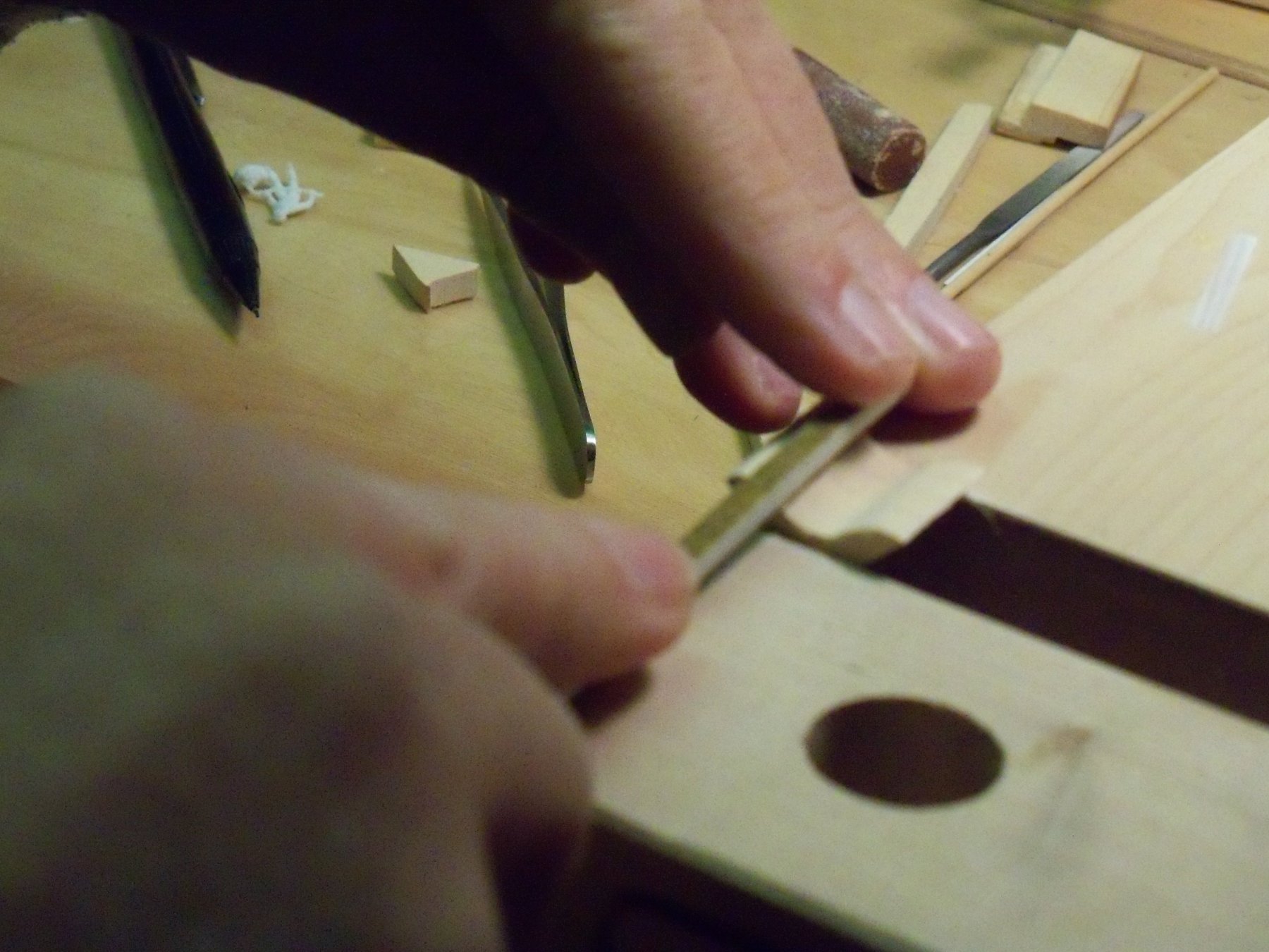
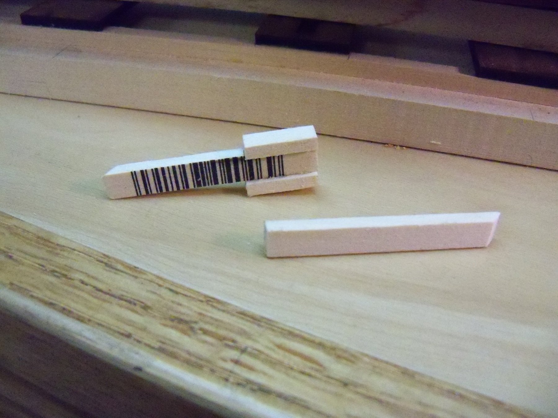
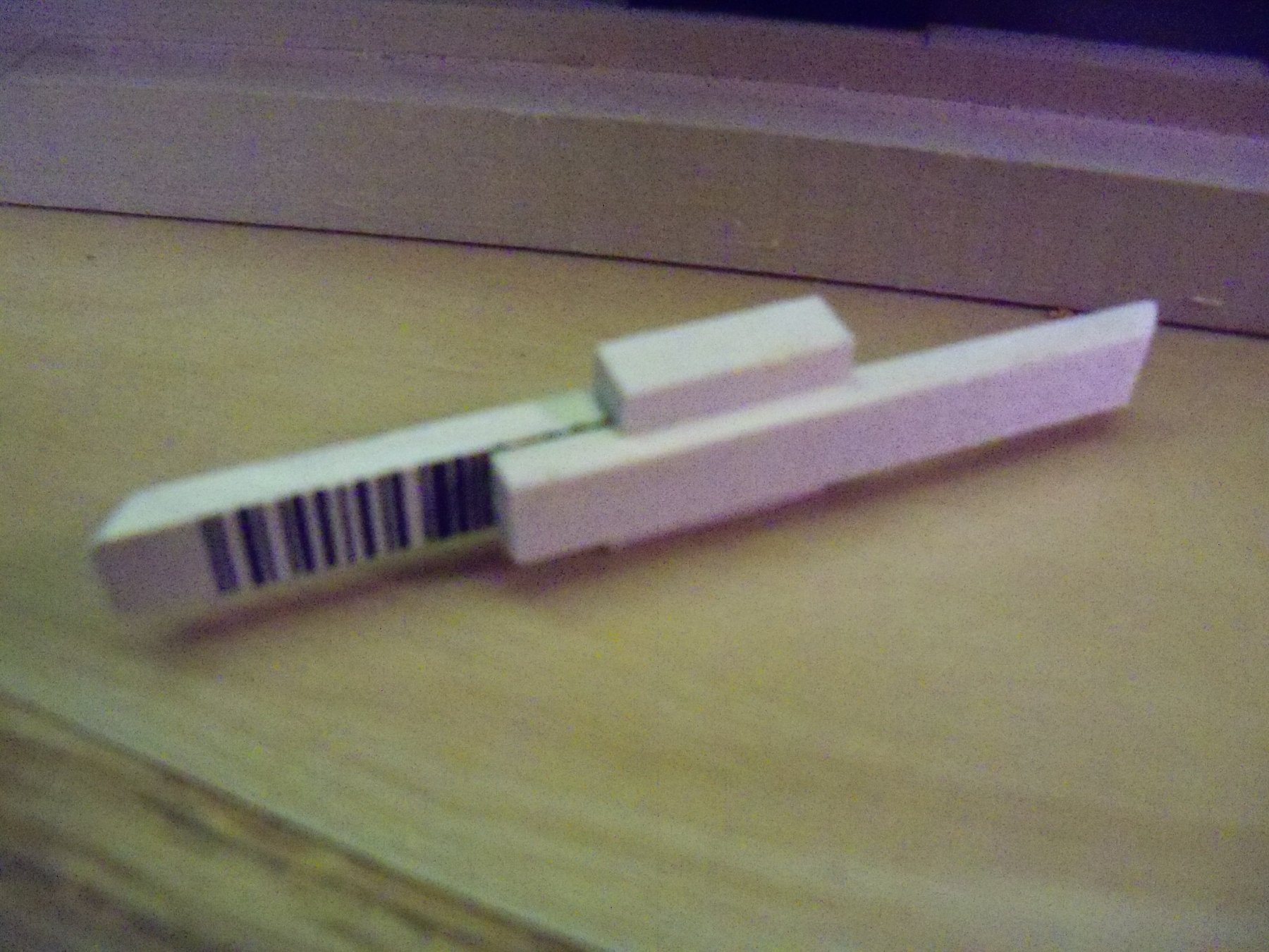
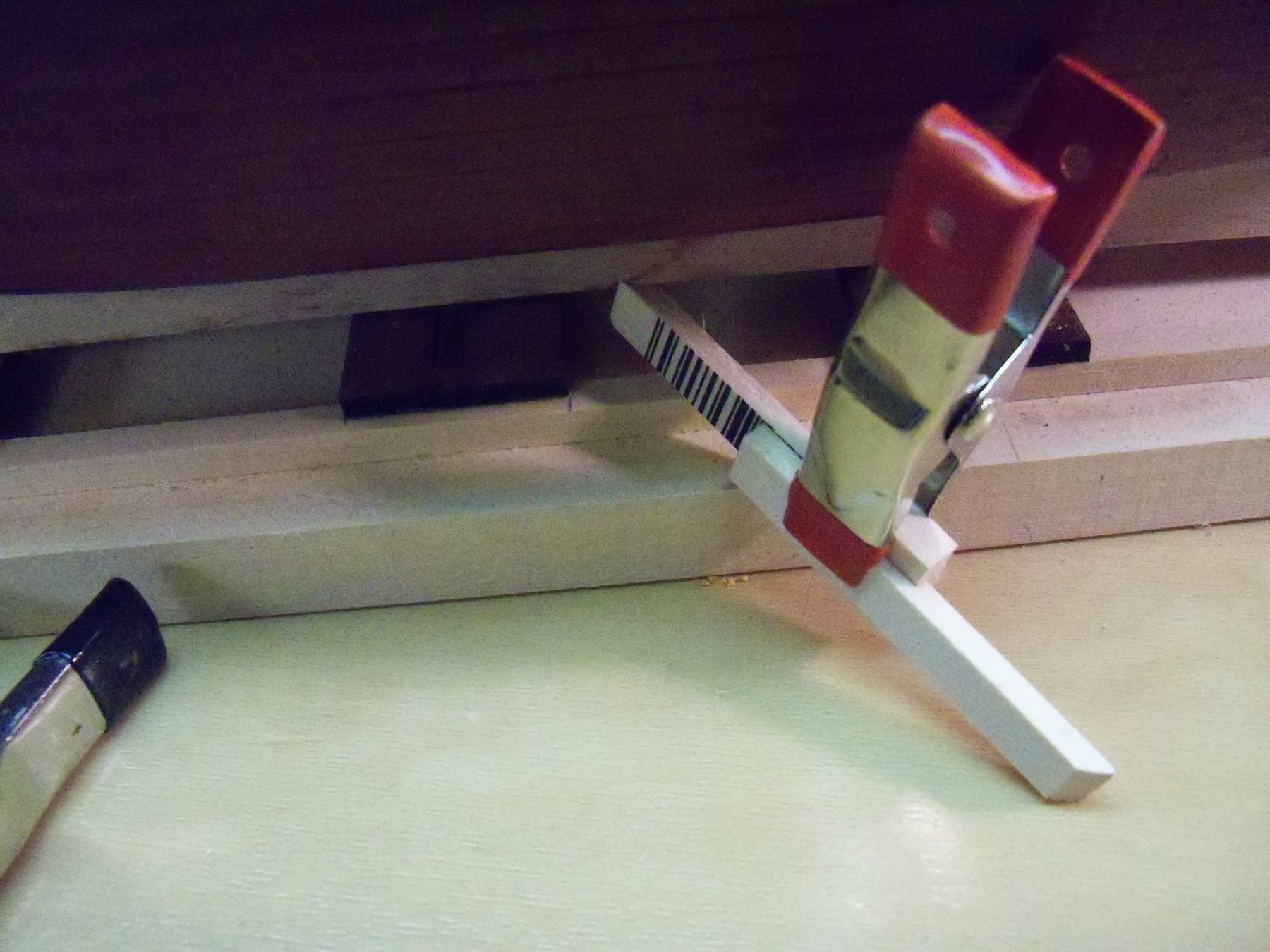
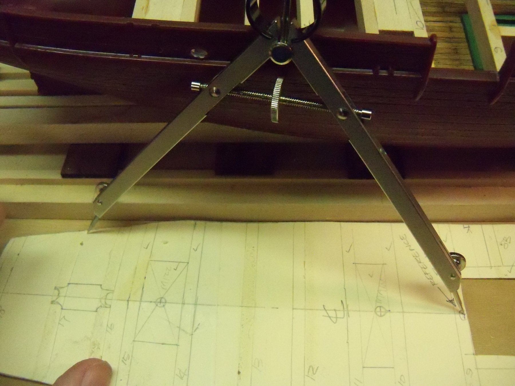
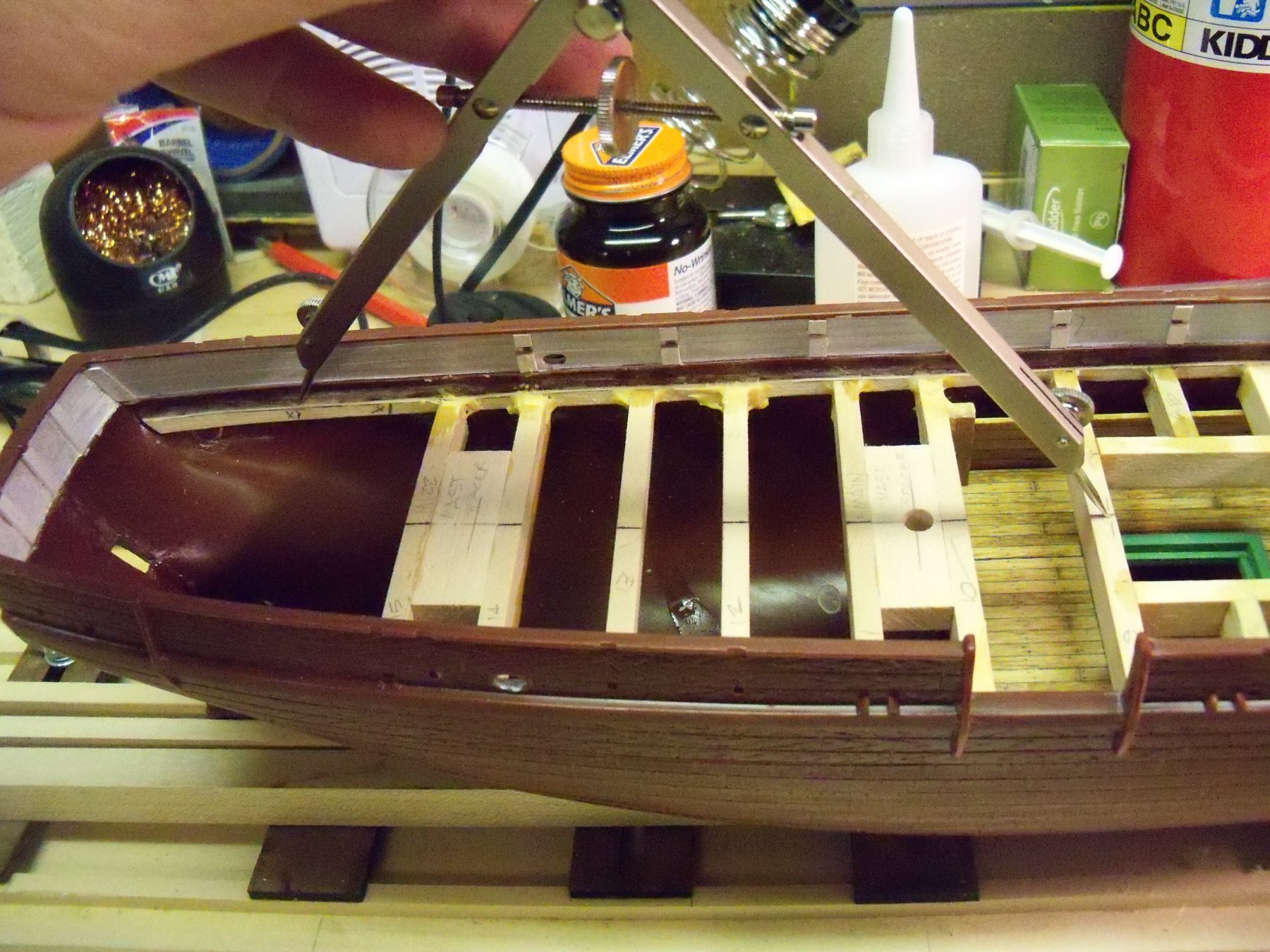
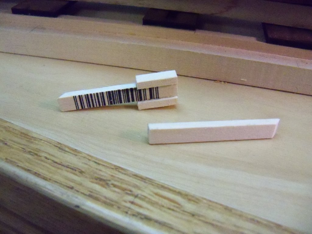
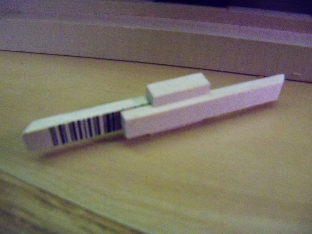
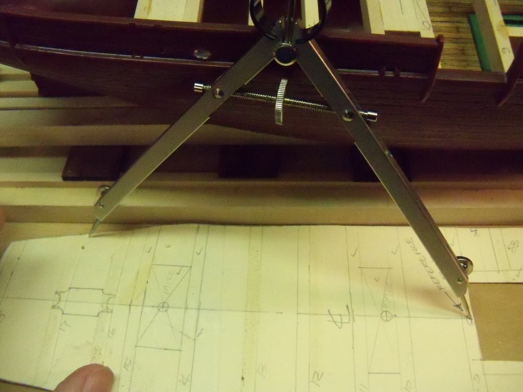
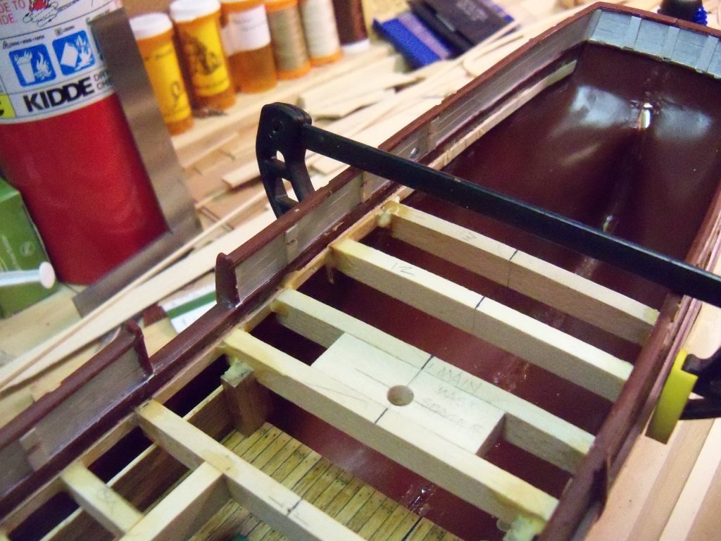
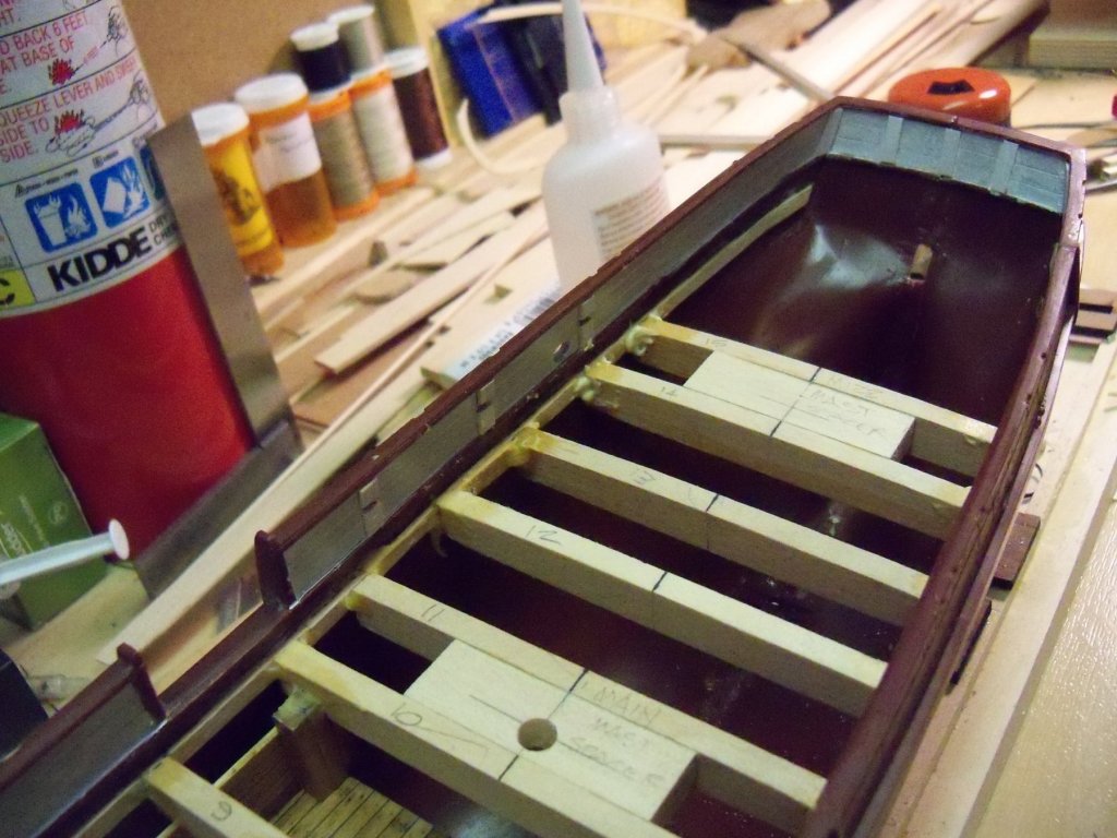
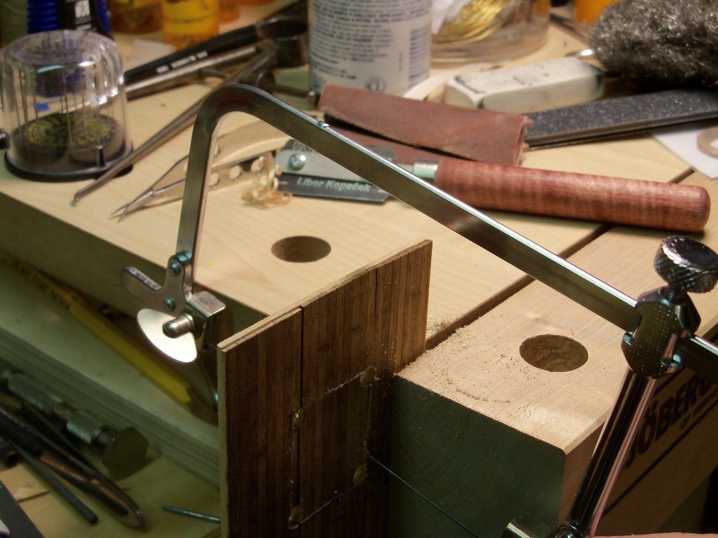
As I continue to replace the deck beams, I thought I should show how I remeasured and re cut them to fit. I decided to make a small version of a measuring jig that my grandfather taught me a long time ago to make the inside measurements for the deck beams easier to make accurately. Of course the jig that he showed me was quite a bit larger as he used it to make furniture. The first photo is the basic four pieces: the two longer pieces have one end cut square and the other end cut at an angle, the short two pieces are just slightly wider than the thickness of the longer ones. The short ones are glued with CA to the edges of one of the long ones. The remaining long piece is waxed to allow it to slide easier in the assembly as shown in the next photo with the short pieces to keep the measuring stick straight. All that is needed to complete the stick is a small clamp to hold it in place. The divider takes measurements off of the layout sheet from the reference point by the main hatch to one edge of a beam where it intersects with the ledger on both sides of the template. Then taking that setting on the dividers with one tip on the reference point on the hatch beam and the other on the both sides of the ledger where a tic mark is put on the ledger. Now the measuring stick is stretched out between the ledgers to get the length of the deck beam at that point. The length is marked on a scrap of paper and the center is found. The beam is then marked so the same amount can be trimmed off of each end. Once the maximum length is marked, the beam is trimmed down to include the angle of the ledger. Slow trimming with a lot of rechecking the fit often is required here. Nothing to it! It just takes awhile.

-
Heinrich This type of adhesive is maybe better known as "super glue". Technically it is cyanoacrylate or CA for short. It has a penetrating action that acts as a sealer on wood. It will also bond metal, plastic, glass, jewelry, and by the way your skin if you are careless. It comes in three basic consistencies. First off there is thin, which flows into the tightest joints and will cure in 1-5 seconds. Second is the mid-cure that is a bit thicker and can fill slight gaps, curing in 20 seconds. (Most commonly used.) Then there is also the extra thick slow cure formula that will fill larger gaps and cures in 90 seconds. This one is best for laminating sheet materials or other large surfaces, as it allows more time to position the pieces. There are two other products that are commonly used with CA. There is an accelerator commonly referred to as zip-kicker that when sprayed on an AC glued joint will make it bond instantly. The other one is a debonder that dissolves CA adhesives, removing cured residue from your tools, clothing, and most importantly your skin if you have a mishap. Some of us swear by it, while others won't use it unless absolutely necessary due to some of the side effects of prolonged exposure to the fumes, so it is generally advised to use in well ventilated spaces and to avoid inhaling the fumes. It is commonly available here in the US modeling shops and even in beauty supply outlets as it is often used for false nails. There are numerous references to these products in MSW build logs. Hope this is of some help.
-
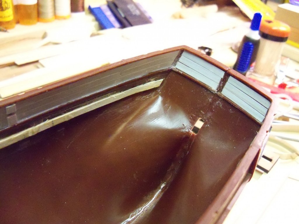
Today I cut some white adhesive foil strips on my rotary cutter to give me three rows of planks to fill in the inside face of the stern bulwarks. Once they were applied I cut out a space for the center stanchion as shown. Using thick CA, I attached the center one, clamped it temporarily, and repeated the above steps for the other two. The two in the corners were a bit trickier as they had to follow the slope of the sides, but eventually they were similarly applied. Some watered down white paint was then applied to both the planks and the stanchions and set aside to dry. The next deck beam (12) was trimmed down equally from both ends, tack glued with thick CA, clamped in place and given fillets of carpenters glue to solidify the installation. This was repeated for the following beam. (13) The next two beams (14 & 15) that were previously ganged together with blocking for the mizzen mast were also similarly installed, although trimming four ends at one time was a lot more difficult to handle. When I get back to working on it (hopefully tomorrow), I will continue to trim and reapply the remaining deck beams

-
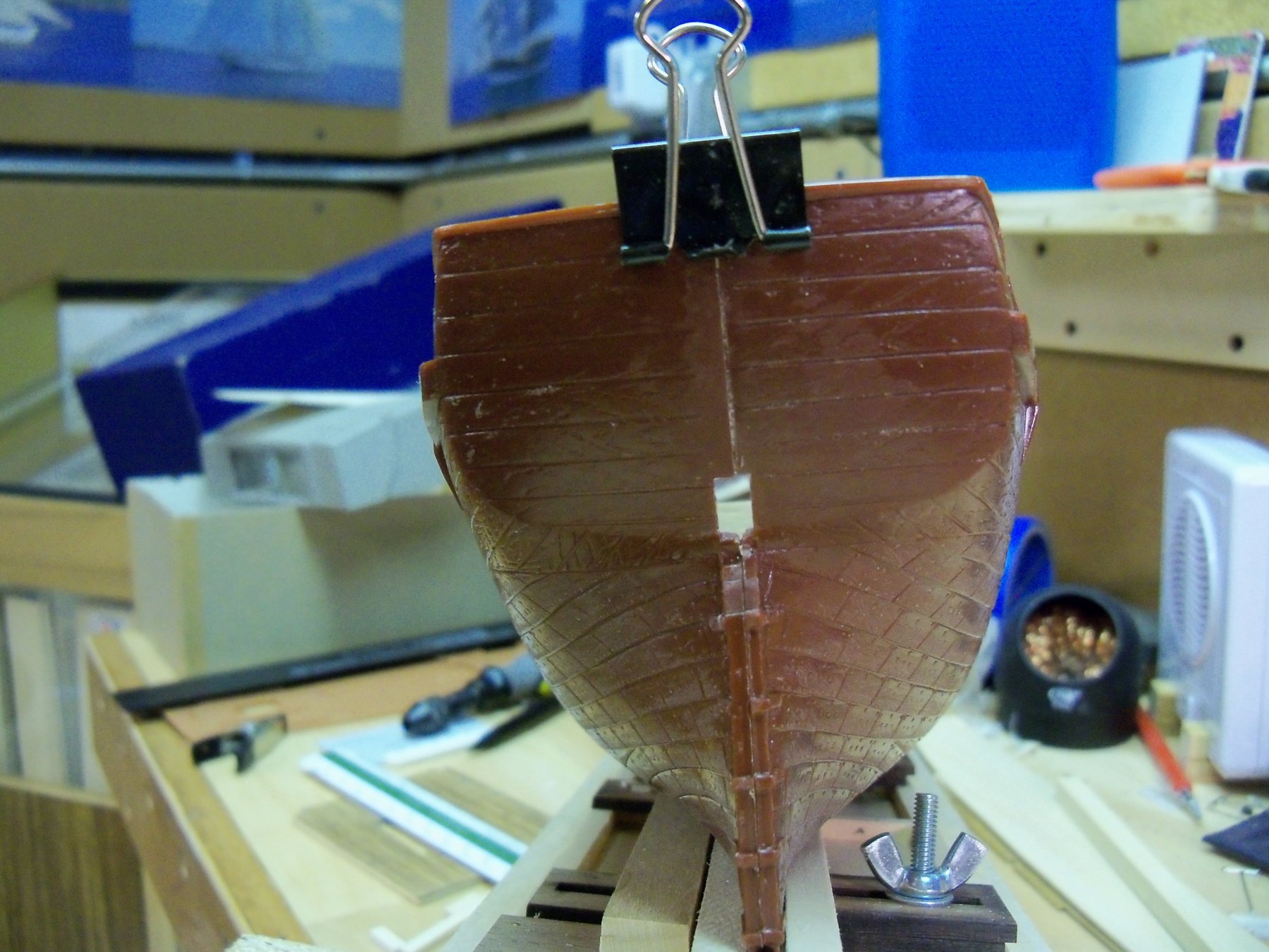
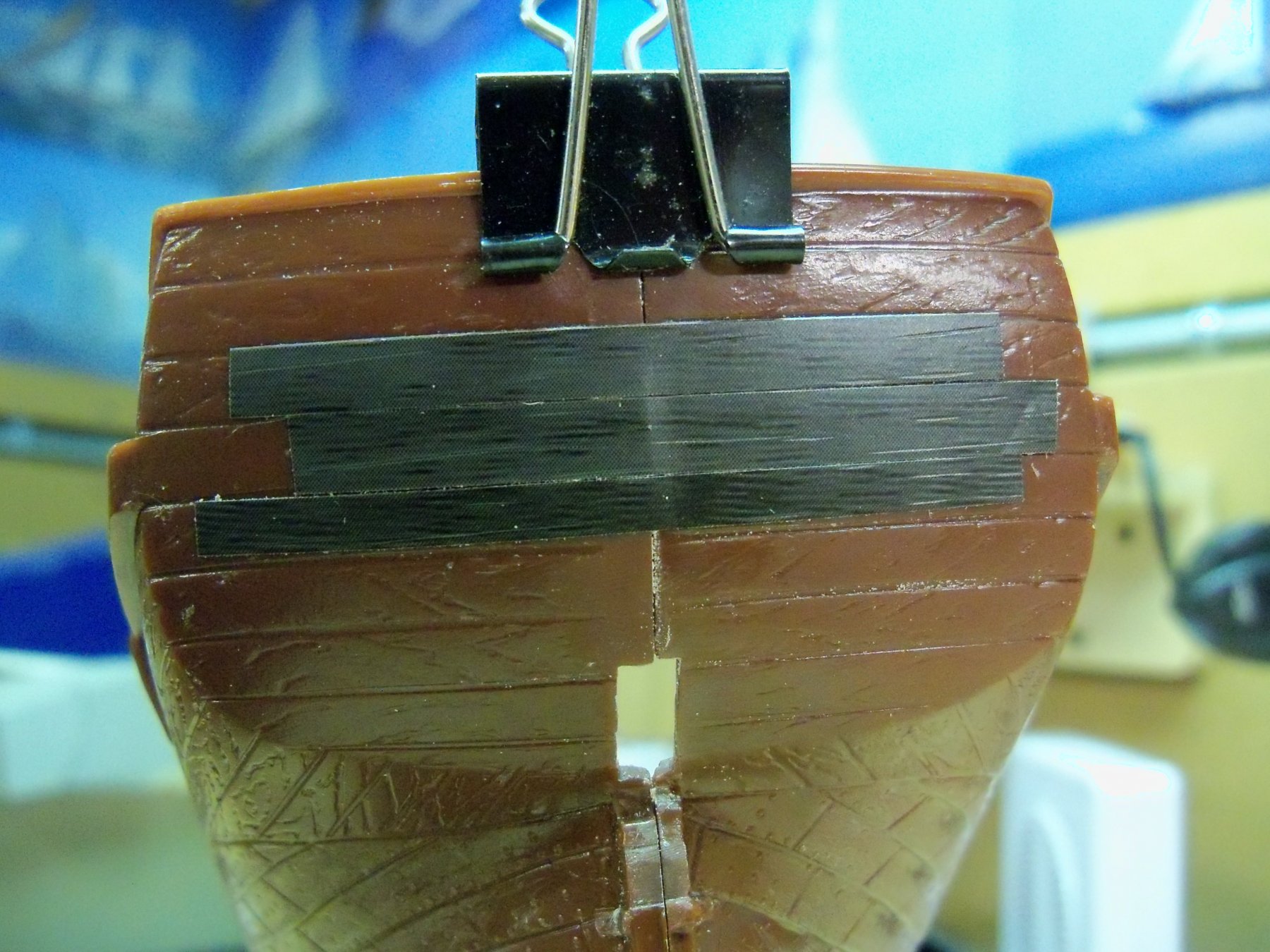
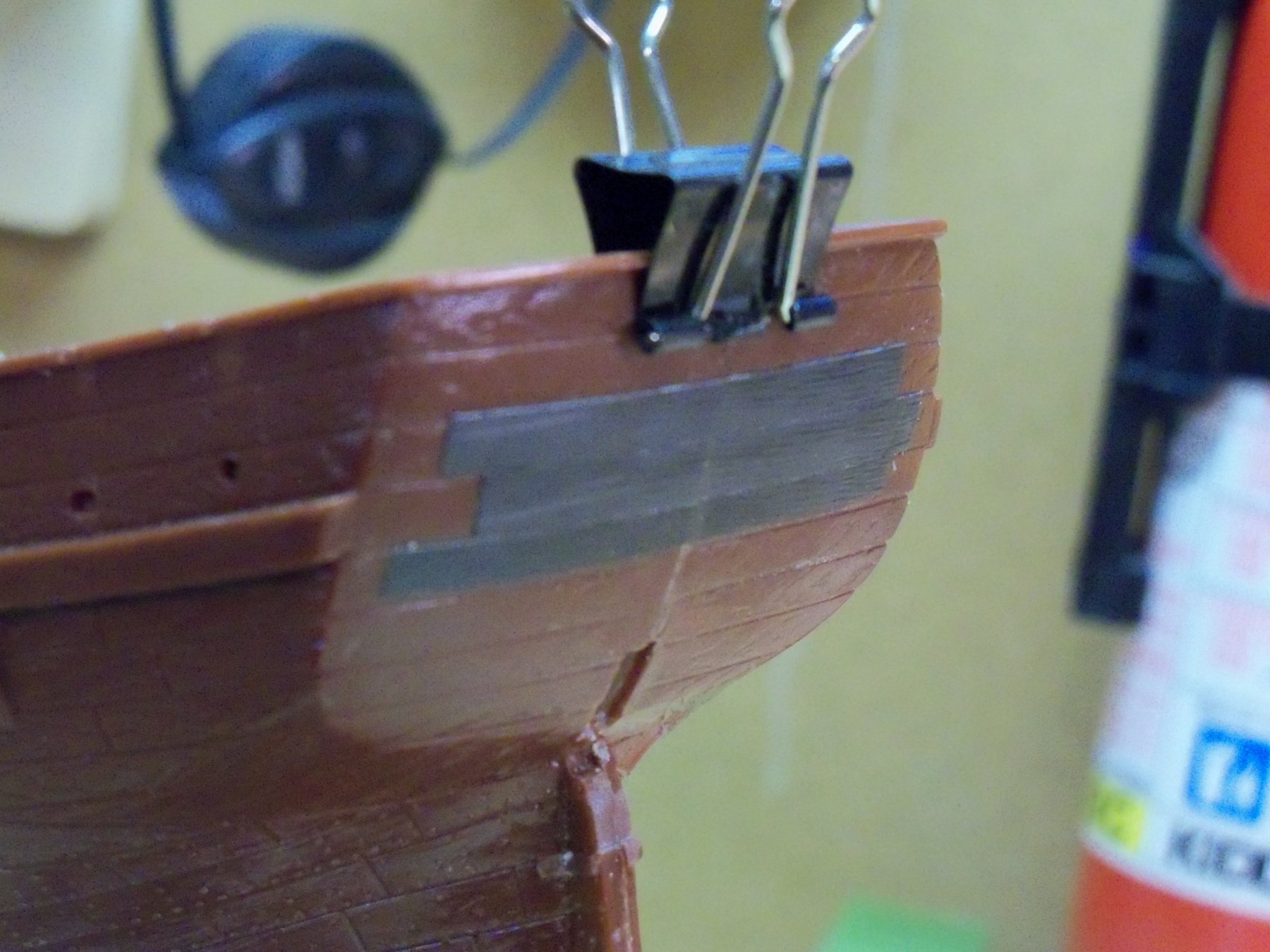
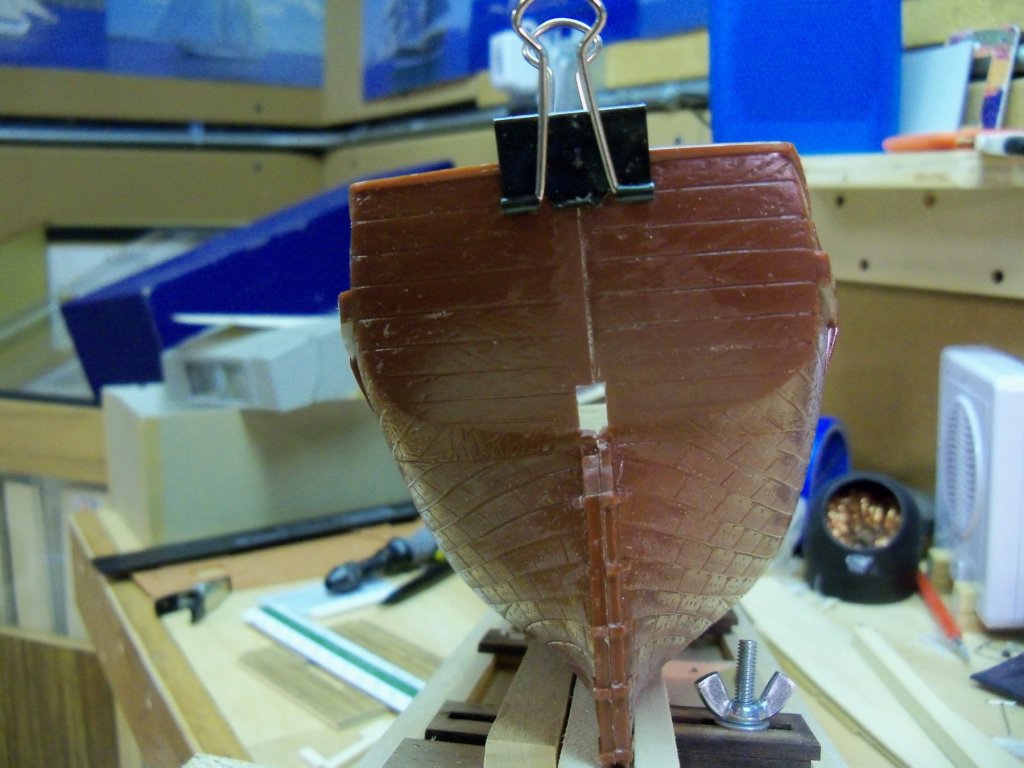
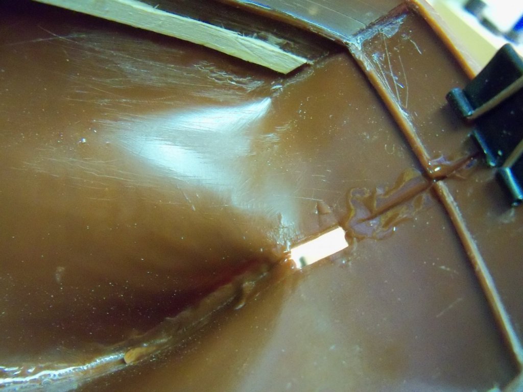
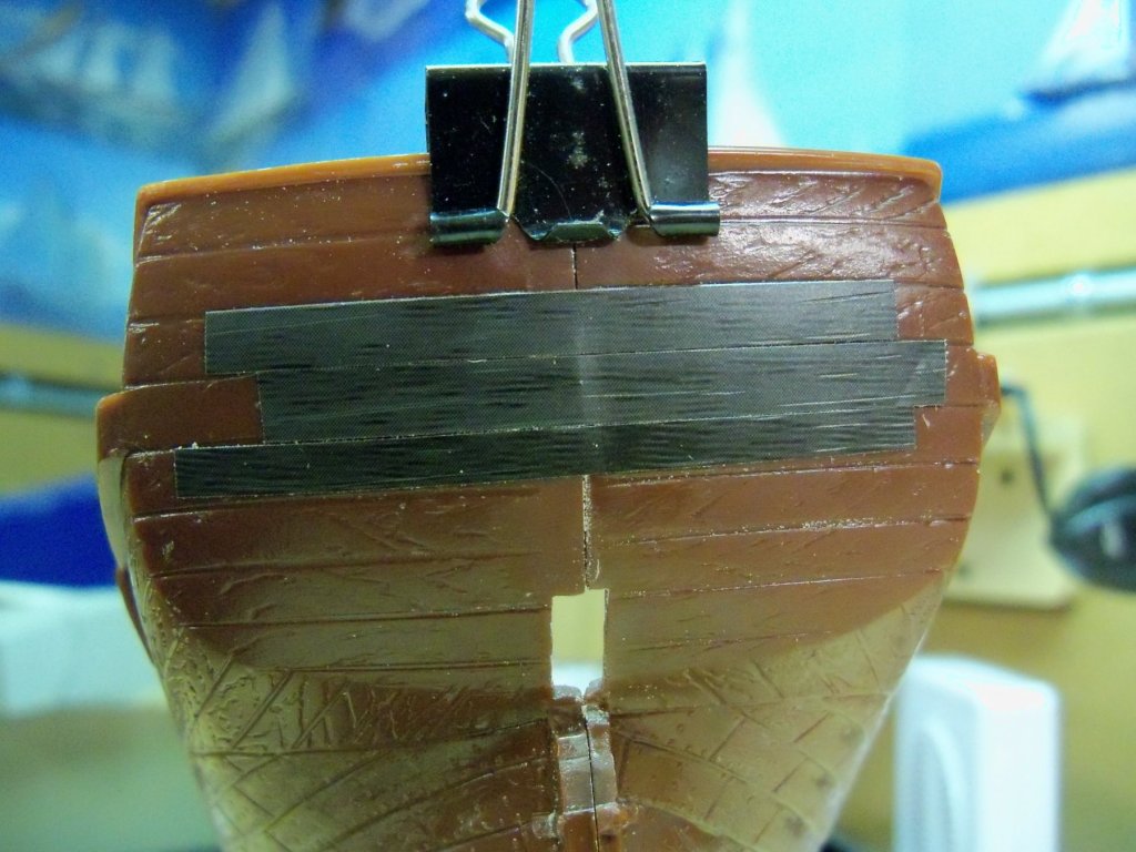
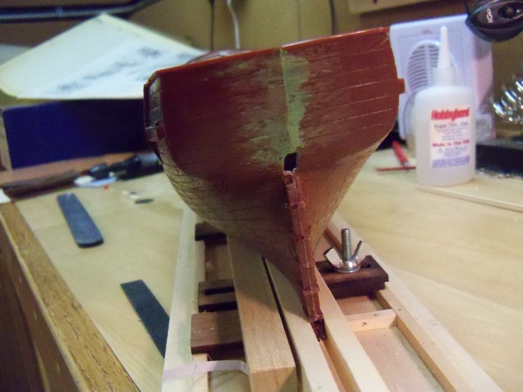
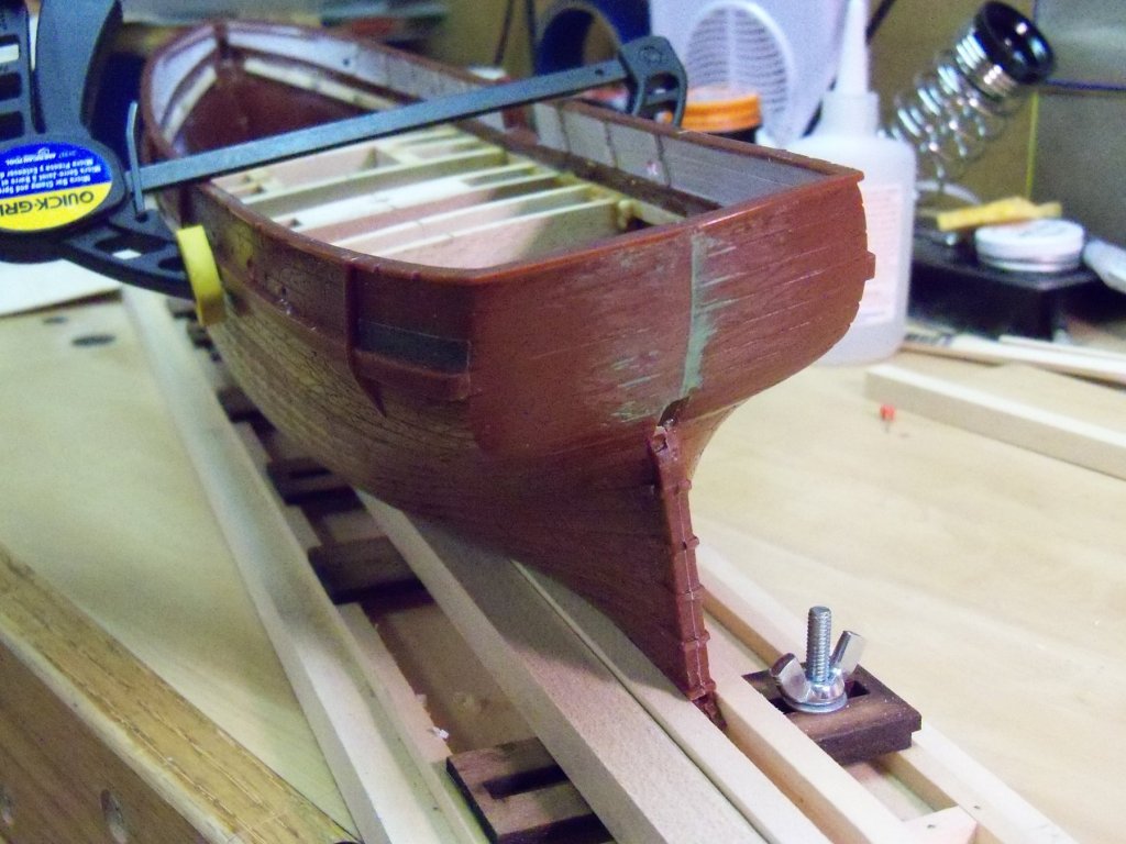
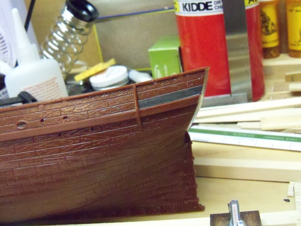
After pondering how to fix the misaligned transom for a while, I tried out a few different ideas. The one that I have settled on is to cover, not only the transom, but the entire wooden portion of the outer hull with the adhesive foil technique that Doris employs. The first step was to fit the transom the best I could with some filing to get a better fit. Once satisfied with that, I clamped it together as shown below. I then put a heavy coat of plastic cement on the inside of the stern of the ship as shown here. I let this sit overnight before continuing, to make sure nothing would shift on me. Taking my black roll of adhesive foil to my rotary cutter, I cut a few pieces to match the width of the transom planks. I applied a few of these strips to the transom as shown here. As you can see, the seam was still quite visible and needed some more work yet. I applied some filler and tried sanding down the seam to allow the foil to disguise it. I tried applying a strip of foil on the curved portion of the bulwark to see how well I could match the curve. With a bit of heat applied to the foil, I could see that it might not be as difficult as I first thought. Tomorrow I will try finishing the inside of the transom bulwark.

-
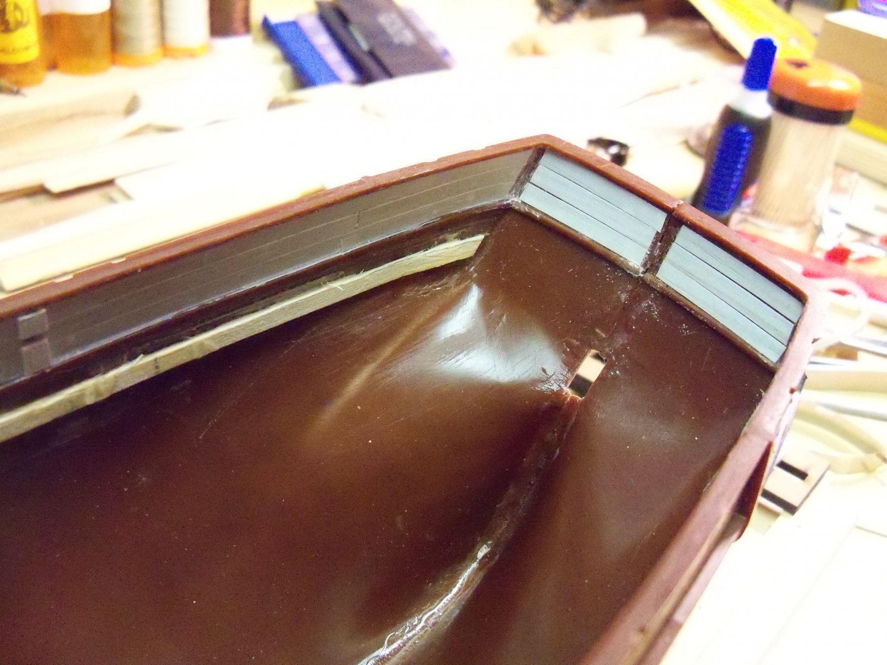
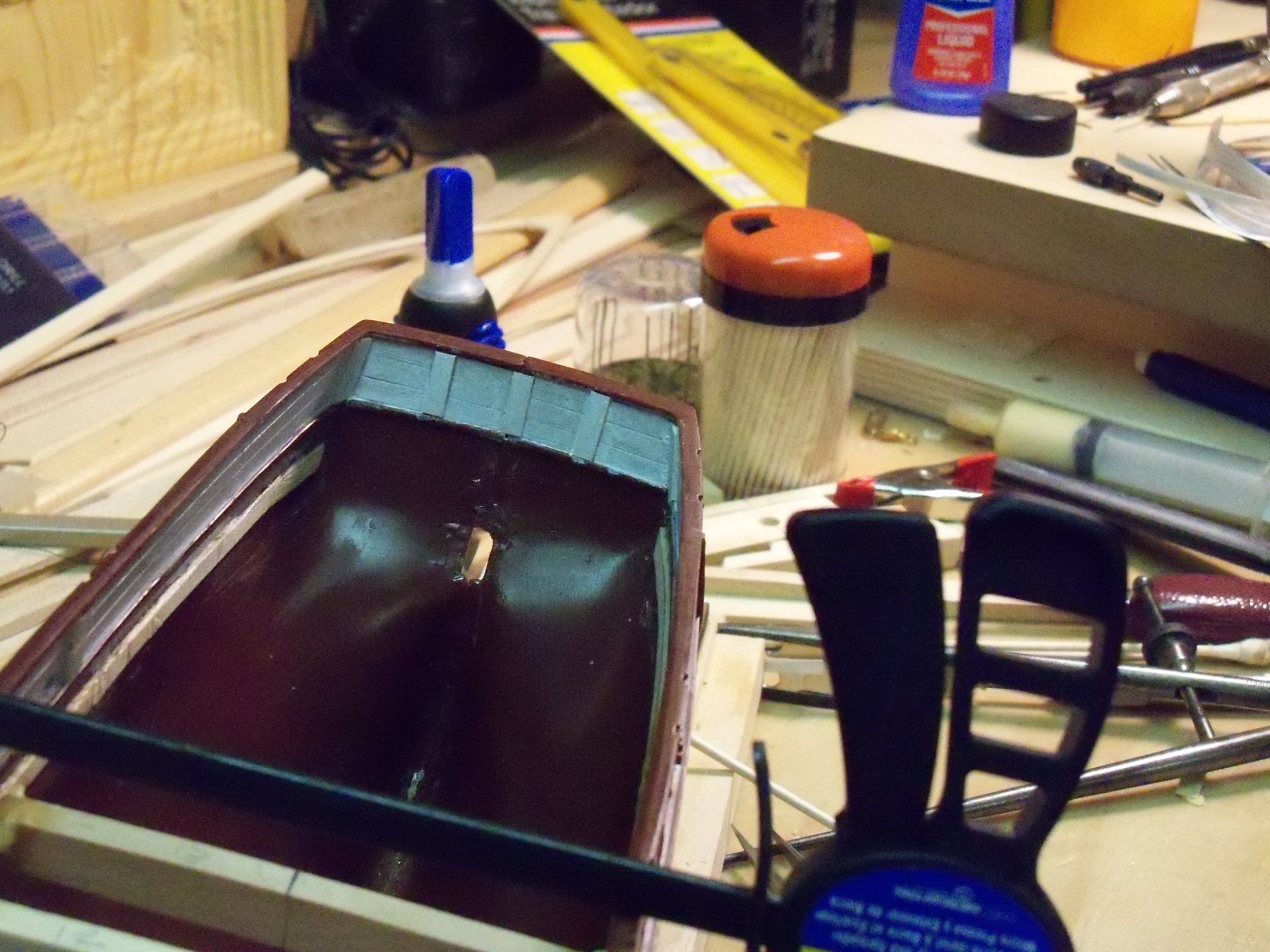
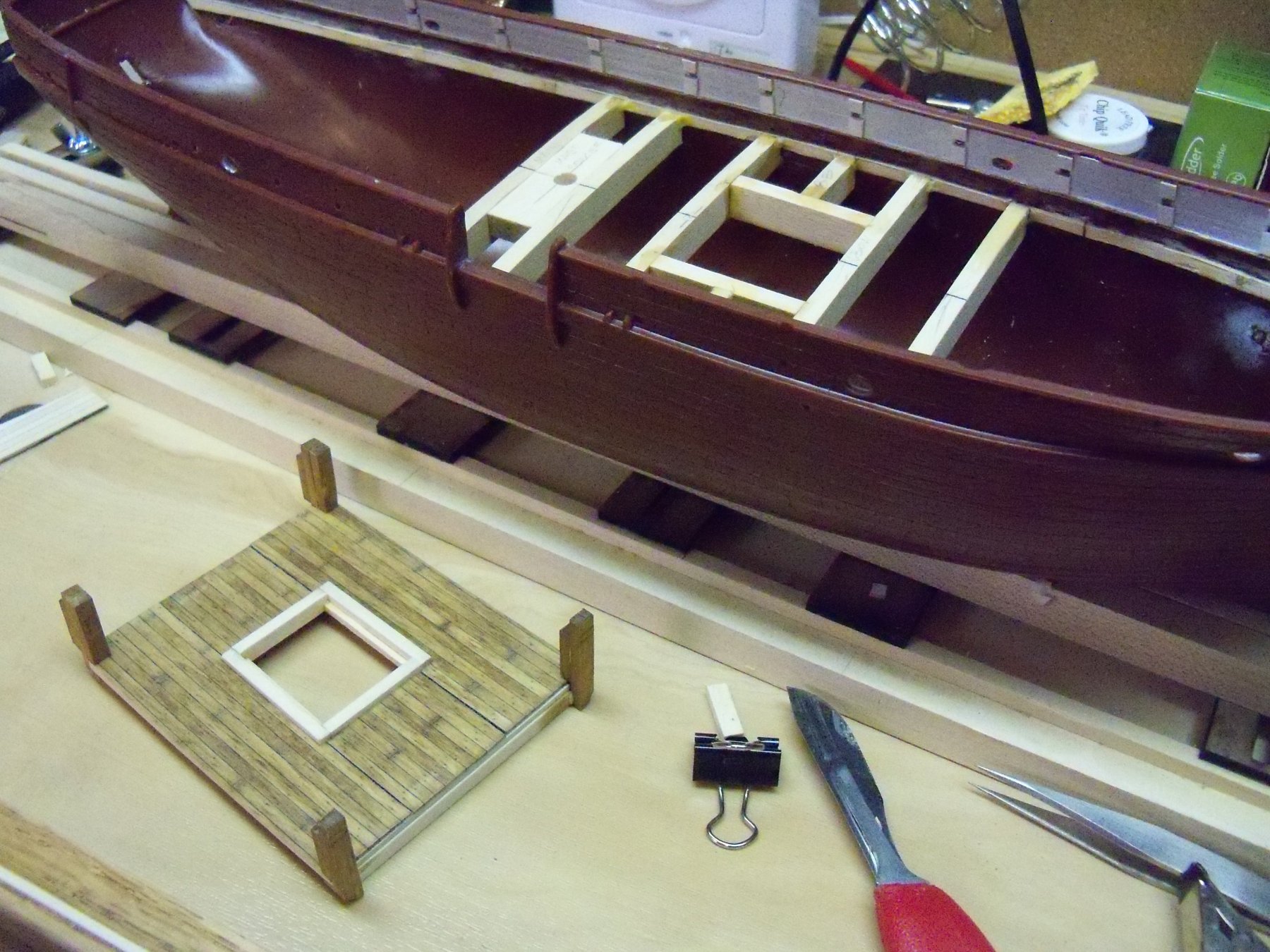
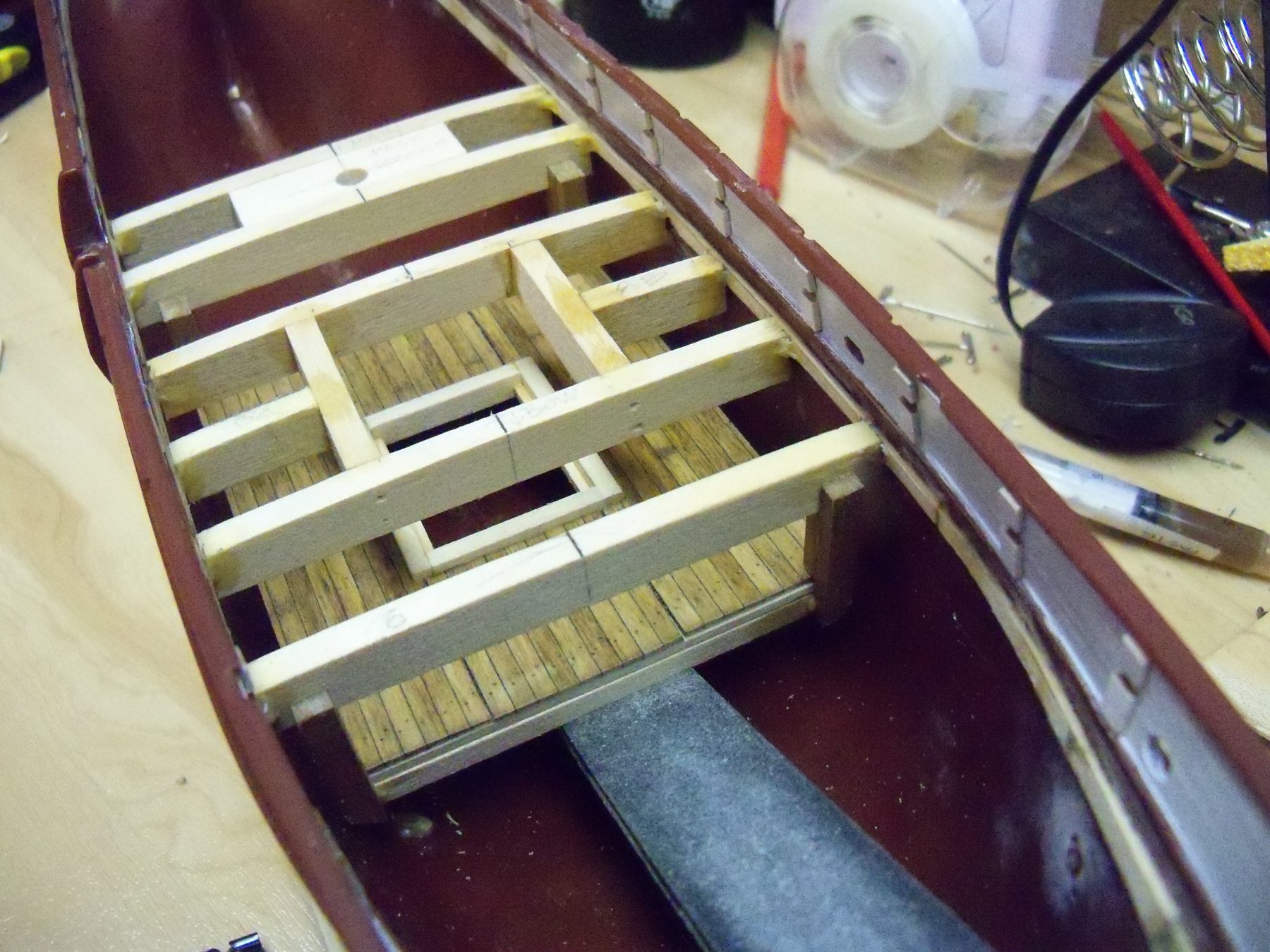
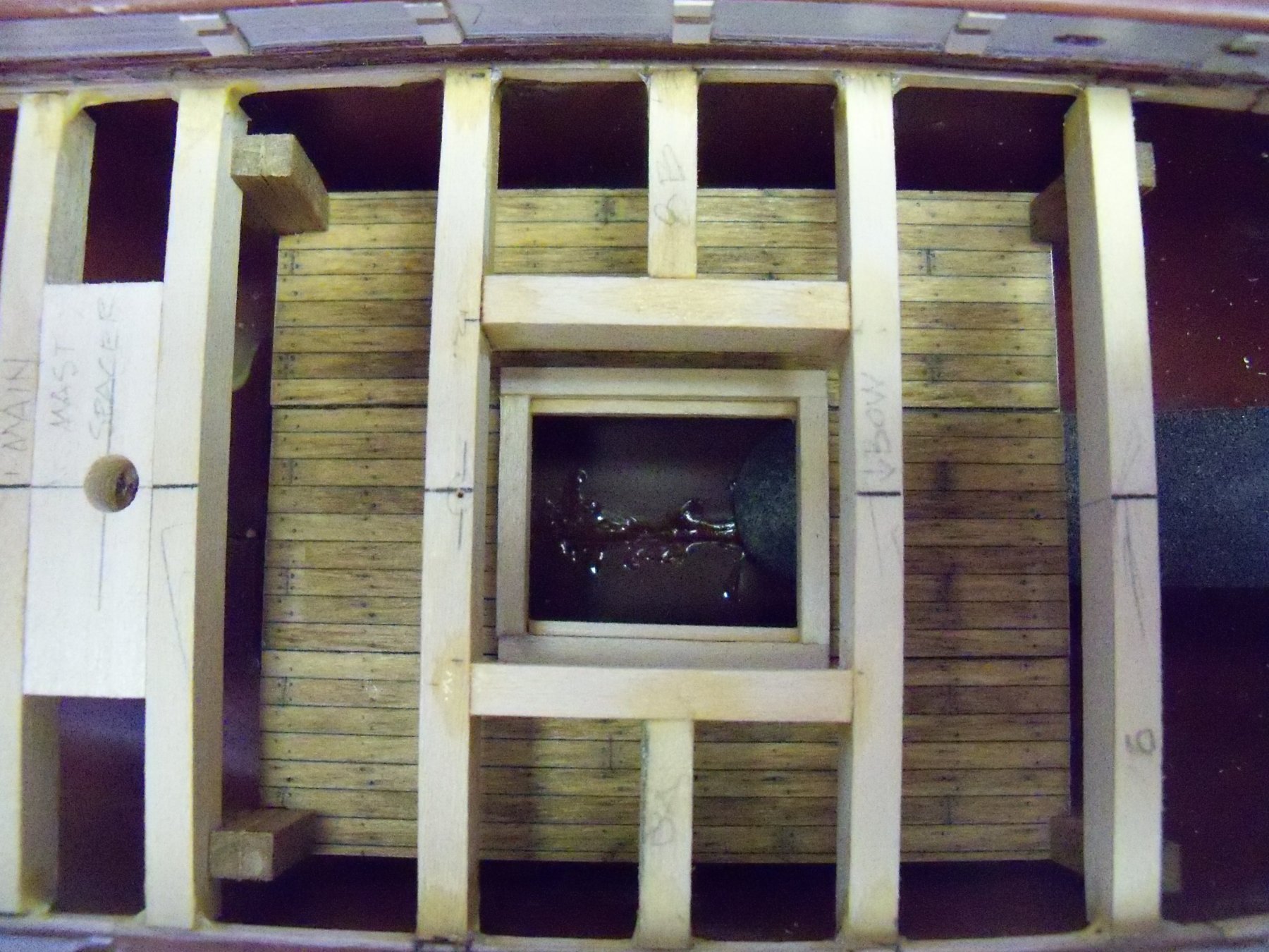
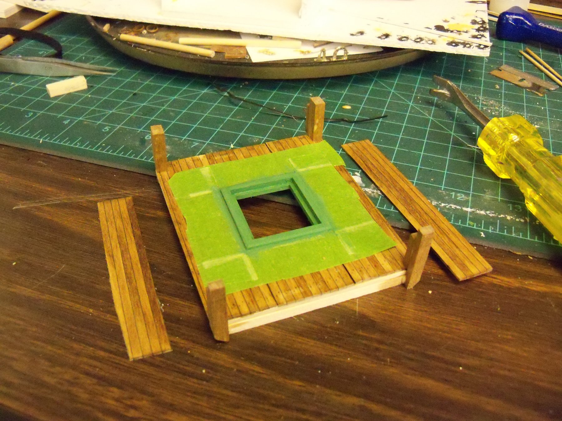
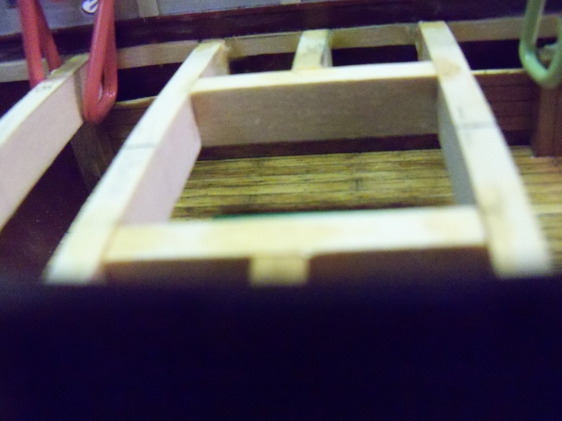
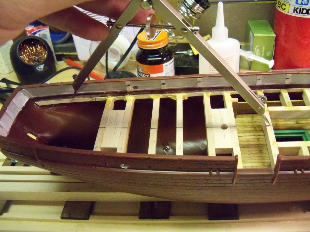
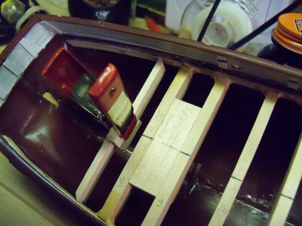
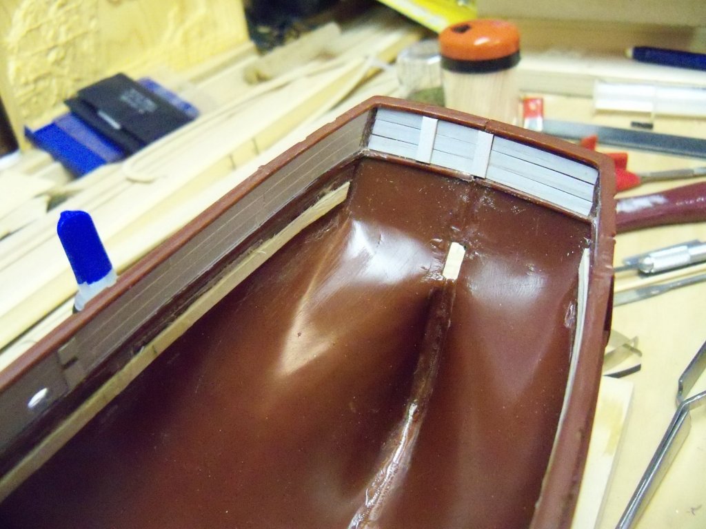
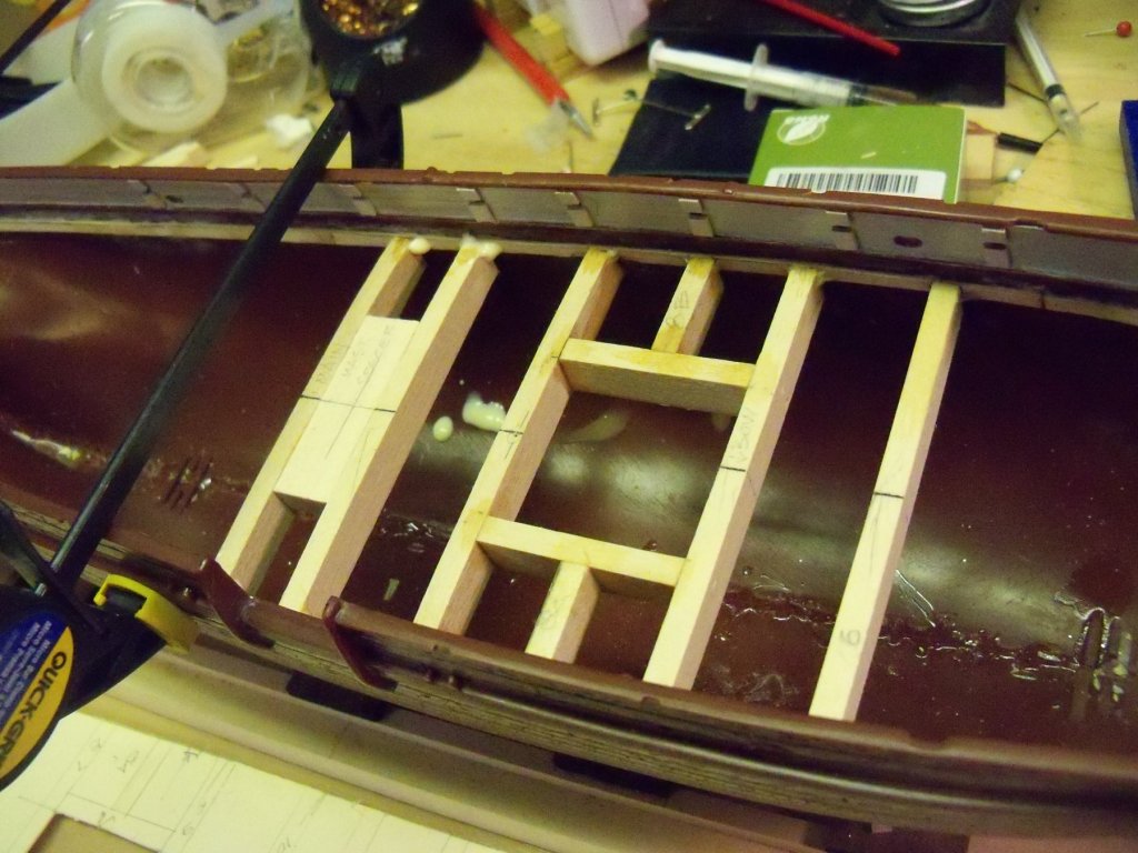
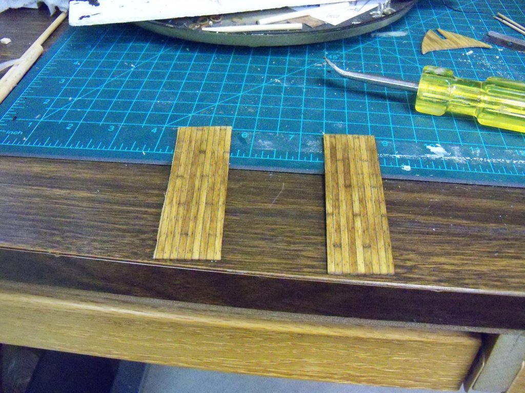
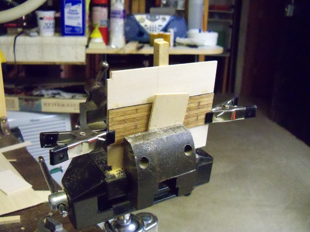
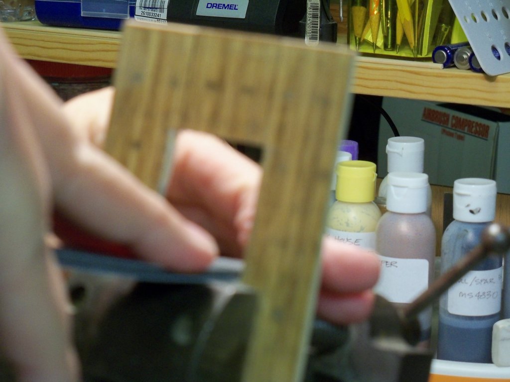
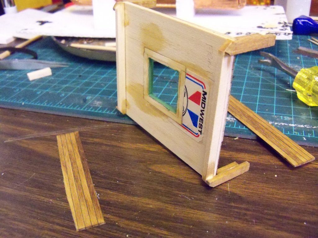
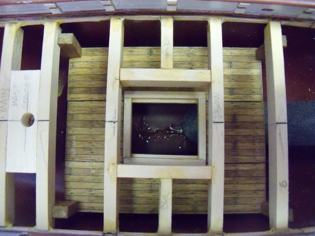
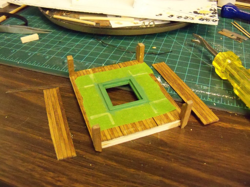
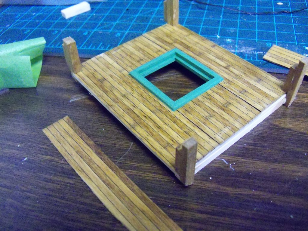
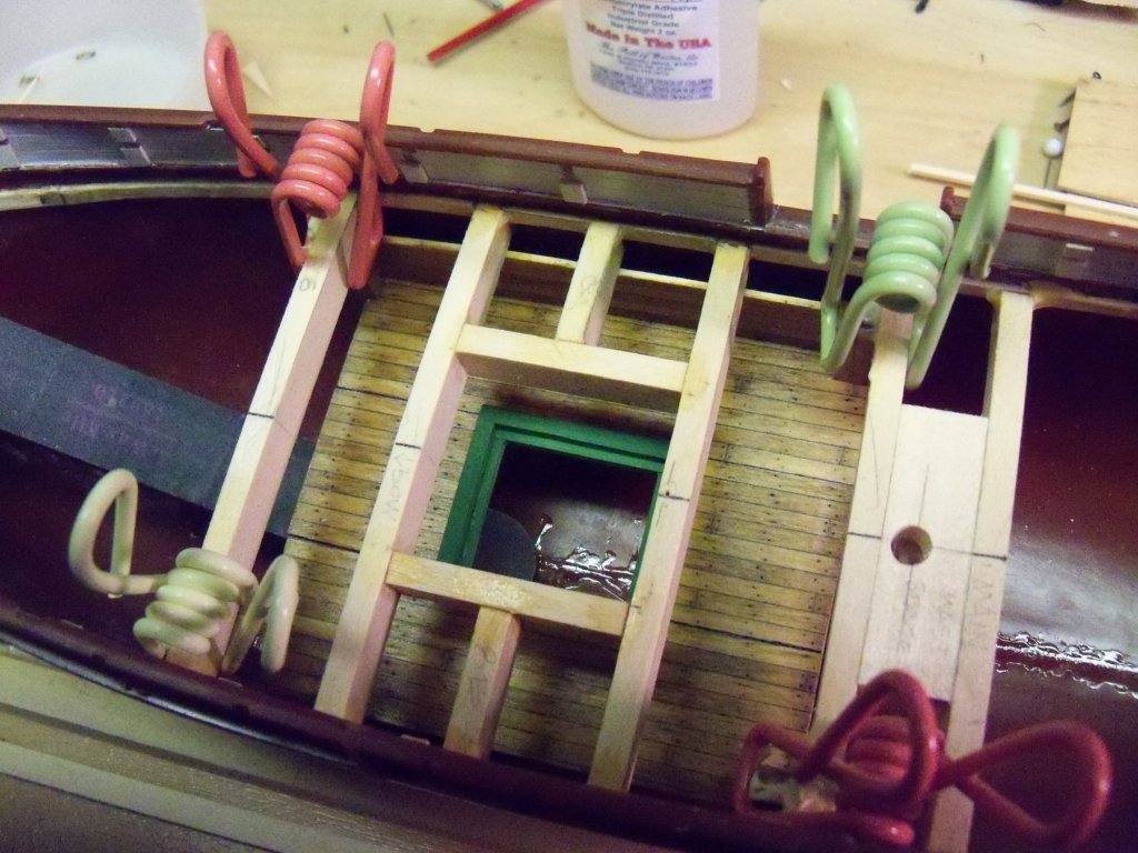
Here and there, I have been able to gain access to my basement model shop for a little work on my Wanderer. When I left off before, I had just removed all of the deck beams to correct errors in their lengths. Six of the frames shown in photo below were trimmed to the correct lengths and glued back in place with carpenters glue and put aside overnight to set. These six were done first so that I would have easier access to suspend a partial lower deck visible through the open upper hatch. I sized the lower deck length to equal the distance from one beam beyond the hatch frame to the stern and one beam to the bow. The width was sized to span across the inside of the hull at approximately a scaled 6’ below the upper deck and still allow some clearance for the lower deck framing. To make the inner deck, I trimmed three left over scraps of pre-made 1/32” thick decking to be applied to a sub-deck of 1/16” thick piece of sheet basswood. I repeated my earlier method of marking the deck plank ends and treenail impressions. I stained and sealed them to match. Once dried, they were glued with carpenters’ wood glue and clamped to the sub-deck. I first used a vice for the center portion and then heavy weights for the outer portions to ensure a flat deck. Looking through my copy of Whale Ships and Whaling by Albert Church, I found an ink sketch of the wooden cooling tank between decks of the bark Commodore Morris that also showed an inner hatch with a coaming. While not the Wanderer, I assumed that it was probably similar. So I decided to trim the opening with a coaming similar to the upper hatch for it. I marked the location and size of the hatch to align with the upper hatch and bored holes in the four corners, and used a fine coping saw to cut the opening. Once it was rough cut, I took a sanding stick to trim it down to the final size. (Opps, looks like the camera focused on the wrong subject!) To suspend the lower deck from the upper deck I took some 3/32” x 5/32” basswood to make a pair of U shaped frames for suspending the front and rear edge of the lower deck. I cut one piece the length of the deck width for a horizontal beam and glued a pair of 1” long posts vertically at each end of the beam. These U-frames were set aside to dry. Once they were set, I sanded the bottoms of the U-frames to allow more clearance in the hull. I cut four spacers to give me a scaled 6’ ceiling space between decks. The U-frames were glued to the front and rear of the inner deck and the spacers were glued to the 1” vertical posts leaving an open notch for the lower deck and an overlap at the top to be attached to the deck beams above. For the coaming itself, I cut some more 3/32” x 5/32” basswood to length for the outer trim and some 1/32” square basswood for the inside ledgers and glued them all in place with CA. The assembly was slid in from the stern and past the front deck beam to test the fit and propped in place with a sanding stick. At this point it looks good enough to me. I masked off the lower deck and gave the coaming two coats of paint and light sanding between. I took a couple narrow pieces of decking to serve for the interior hull sides and finished them to match the deck. The masking was removed and it was ready to install. The assembly was slid back in with the side pieces unattached, glued and clamped in place. (I tried with them attached before installation but didn’t have enough clearance to slide the whole assembly in place.) So, now with a lot of fiddling and cussing, the side pieces were glued into place. I measured the hatch opening before installation, as I was not sure if the hatch would be solid or a grating, so I just left it open for now. As you can see here, the sidewalls were maybe a bit much, as they are not easily seen, but maybe a couple of subdued LED lights would help. I’ll give it some thought, as I was impressed with the way Doris did it in her ships. I plan on installing a few knees that would also be partially visible and maybe an oil cask or two. So, now that the lower deck is in place it's time to decide what to do with the transom problem. I will experiment with a couple of solutions and get to it!


- 107 replies
-
- 10
-
-
A fairly recent Clint Eastwood movie called: Trouble With the Curve, is something that you apparently have no such problem with!
-
Now that's what I call literally getting down to the nuts and bolts of things. Some would swear that you must be doing this at a full time professional level.
-
Doris Are these added beams actually wood or card? Am I to assume this to be some type of spray fixative or sealant to make everything more permanent?
- 1,035 replies
-
- 4
-
-
- royal katherine
- ship of the line
- (and 1 more)
-
Yes, but you get a better view of the sail rigging without the sails blocking your view. You just have to use your imagination a little bit.
-
And to think that I have trouble with 1:96 scale!
-
You might try to use the foil technique that Doris uses. I have employed her method for my Wanderer and it's easy to do with very effective results, especially when the foil has an embossed wood grain.
-
If that is true that they are as good then I would gladly buy them as Floquil was my favorite despite the fumes. I still have a few bottles from the 60's that are still usable. (As opposed to Model Expos, which even when freshly bought are often just colored hockey pucks in a jar.)
- 140 replies
-
- 6
-
-
- the sullivans
- trumpeter
- (and 2 more)
-
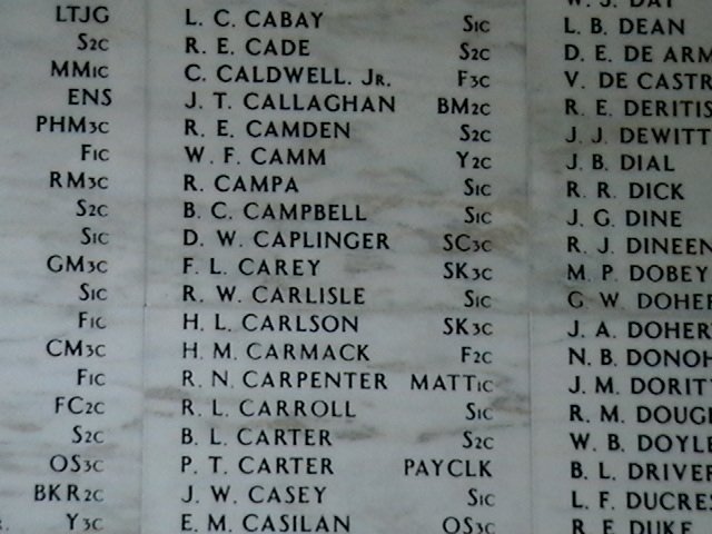
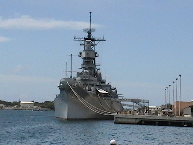
Personally, I have had very little opportunity to see this ship, having only seen it from a distance, but your model really makes it come to life. You reveal so many details that even had I been on this ship, I would probably never have even noticed. My only view of this ship that ended WWII was from a memorial for another important warship where it all started, the Arizona. Back before becoming wheelchair bound, we made ten trips to Maui. On most of these trips we spent part of our time on Oahu and made four visits to the Arizona memorial in Pearl Harbor. On the first visit we were with two of our friends from WI. The visit for me was more emotional than I thought it would be as my father served in WWII and a distant cousin of ours was a member of the crew on the Arizona. When it was sunk, he was one of the ones that ended up entombed in her hull. It was one reason my father enlisted right out of High School, despite his father’s objections to doing so. Now you would think that as he was someone that I only knew of vaguely through my father’s side of the family, that it wouldn’t really choke me up like seeing his name etched on the wall in the memorial did. I took several photos of the listing on the wall including a close up (shown below) of the portion showing our cousins name to take back to show my family, as I was the only one to go there and see it. My uncle used to live on Kauai for several years, but he never saw it. That aside, we went to it three more times with various friends and despite having seen it before, I was always affected the same way. The last time there, my sister from New York was with us and she seemed to be likewise affected. All this over someone we never knew. So, in 1999, I think it was, the USS Missouri became a part of the Pearl Harbor memorials and tours of the ship became available to the public. However, by that time I had to walk with the aid of a walking stick and was not able to go aboard her as there were very steep access ways, not to mention all the ladders to negotiate once aboard. I did, however, get a good telephoto shot from the Arizona Memorial ramp that I have included and show below. If I am ever able to return to Hawaii in my wheelchair, things will apparently now be quite different. I have read that he tour is currently available to wheelchair bound visitors as it has become ADA accessible, with a special wheelchair accessible ramp from the dock up to the aft of the ship, elevator access to other decks, and an accessible rest room aboard. As I approach 70, any more visits to this ship become less and less likely. But thank you for showing me and all of us at MSW your excellent representation of the “Mighty Mo”.
-
Kortes Will you be applying a heavy coat of varnish to your model as is shown on all of those harbor photos?
-
Rob I don't know how Doris cuts them, but a simple method that I employ is the use of an inexpensive rotary cutter. If you look in my build log in the plastic kits under the whaler Wanderer dated June 8, I illustrated how it is easily accomplished with this tool. As to the hair dryer, according to Doris, it helps improve the adhesion of the foils. From my experience with her methods, this does seem to be the case.
- 1,035 replies
-
- 5
-
-
- royal katherine
- ship of the line
- (and 1 more)
-
I know from experience what that is like. I started like gangbusters on my Phantom, but gradually the interest started to wane. A friend of mine requested I build a plastic whaling ship model of the Wanderer that I had sitting on my kit to build shelf for him for a change of pace. That is working for me so far, especially as I make some drastic modifications to the kit, and even started a build log for it. I would still be at it pretty heavy right now, if it wasn't for my elevator woes right now. And while I'm waiting for parts of the whaler to dry, I often switch back to the Phantom for a bit of variety.
-
I've been going through your build log for the last few nights and am impressed with your drive to make it as accurate as possible. Not to many modelers will look at some feature, decide they can do it better and then take that one out and replace it with the new and improved version. I tend to do the same thing, so I know the feeling. One thing that I noticed here is that the fore bits go through the main deck into the lower deck, but the aft bits are just pinned into the main deck. Is this the way they are attached on the actual ships or is there something done that just isn't visible below decks? If it was just pinned in place, it would appear that not much strain on the belayed lines could yank it right off the deck.
-
Kortes, I am curious about the function of that coffin shaped area on the fore deck. Does it have something to do with a centerboard?
-
That is one fiddly piece of trim to make! Not only does it have to follow the double curve of the hull, but also had to have notches cut to match. Did you wrap it with three separate pieces of foil or just one? If it was one piece, how did you avoid having the foil on the two sides bunch up when making the foil go over the curved surface of the trim?
- 1,035 replies
-
- 5
-
-
- royal katherine
- ship of the line
- (and 1 more)
-
Need help with saw blade output
BETAQDAVE replied to bigcreekdad's topic in Modeling tools and Workshop Equipment
Yes, kickback can actually be lethal sometimes! Was in an woodworking class once where a full size table saw shot a good size sliver of cedar right into the stomach of its operator. He was even wearing a shop apron, but the wood still went right through it to penetrate his intestines. Infection from both the wood and clothing fibers set in and he died about a week or so later from that infection. Better safe than sorry really is the way to go! While it's true the Byrnes saw we're talking about here is not a full size saw, but why take chances, stay out of its line of fire!!! -
Of course, all of us do realize that paper is merely a by product of wood anyway, right?
- 1,035 replies
-
- 10
-
-
- royal katherine
- ship of the line
- (and 1 more)
-
I'm afraid that the five pictures above just show up on my screen as tiny boxes with X's.